

Page 1
Number One
AirConditbning
M^er
Division of
Carrier Corporation
CaTiier Parkway • Syracuse N Y 13221
Single-Package Cooling Units
SAFETY CONSIDERATIONS
The 50BA,BB Single-Package Cooling Units are
designed to provide safe and reliable service when
operated within design specifications. However, due
to system pressures, electrical components and
equipment location, some aspects of installation,
start-up and servicing of this equipment can be
hazardous.
Only trained, qualified installers and service
mechanics should install, start up and service this
equipment.
When working on the equipment, observe all pre
cautions on tags or labels attached to the unit,
safety notes in the literature and any other safety
precautions that apply.
• Follow all safety codes.
• Wear safety glasses and work gloves.
• Use care in handling, rigging and placing bulky
equipment.
A DANGER
NEVER reach into unit while fan is running.
LOCK OPEN AND TAG fan motor power dis
connect before working on a fan. Remove the fuses
and take them with you after noting this on tag.
Page
Step 11 — Install return air ductwork
Step 12 — Check return-air filters
Step 13 — Check compressor spring
Step 14 — Make condenser
Step 15
Step 16
START-UP...............................................
Unit Size 50BA,BB004 and 006 ...
Unit Size 50BA,BB008 thru 064 ...
Service Valves........................................
Capacity Control Valve Adjustment
SERVICE
Indoor Air Fan Adjustment
Lubrication
Return-Air Filters
Condensate Drains ................................................. 20
Evaporator Coil
Water-Cooled Condenser...................................... 20
Air-Cooled Condenser........................................... 20
Charging the System
Return-Air Grille Removal
Access Panel Removal.......................................... 22
Indoor-Air Fan Motor Removal............................. 22
Pressure Relief Devices........................................ 22
Crankcase Heaters
High and Low Pressurestats
Time Guard® Control Circuit
(004-012 units).................................... II
mounts
connections.....................................11,14
Install unit drain line
Make electrical connections. ... 16-18
.................................................
.............................................................
..............................................
...................................................
......................................................
..........................................
................................................
.......................
........................
.........
.........
.........
.........
.........
.........
.........
.....................................
................................
................................
11
11
15
18
18
18
18
18
19
19
20
20
20
20,21
21
22
22
22
A WARNING
CHECK assembly and component weights to be
sure rigging equipment can handle them safely. Note
also any specific rigging instructions.
WHEN STEAM CLEANING COILS, be sure area
is clear of personnel.
CONTENTS
Page
SAFETY CONSIDERATIONS.................................... 1
INSTALLATION .......................................................1-18
General ...................................................................... 1
Step 1 — Receive and inspect unit
Step 2 — Protect units from damage
Step 3 — Provide unit support
Step 4 — Rig and place unit
Step 5 — Install accessory plenum,
Step 6 — Position fan section as desired. .. 7,8
if supplied
Step 7 — Install fan motor.................................. 9
Step 8 — Align fan shaft and wheel
Step 9 — Install heating coil, if supplied. .. 11
Step 10 — Install supply air (evaporator)
ductwork
.......................................
........................................
...................
...............
..........................
..............................
7
..........
10,11
11
I
1
4
4
INSTALLATION
General — The 50BA,BB004 thru 024 units are self-
contained units arranged for vertical air discharge
and wired and piped at the factory.
Size 50BA,BB028 thru 064 units are self-
contained units consisting of a base section, fan
section, fan motor and fan drive package, each
shipped separately and field assembled. The base
section consists of factory-wired compressor/
evaporator coil unit. The fan section can be
mounted for vertical or horizontal air discharge
(Fig. 1).
^Step 1 — Receive and inspect unit.
Check unit against shipping order. Inspect care
fully for concealed shipping damage. If shipment is
damaged or incomplete, file claim with transporta
tion company and advise Carrier immediately.
>■ Step 2 — Protect units from damage.
To maintain warranty, protect unit against ad
verse weather, theft or vandalism on jobsite.
Carrier Corporation 1981
Page 2
--M ----
-v^
ALT REAR INLET
VIEW A-A
UNITS 50BA,BB004,006,008 AND 012«
UNIT
50BA.BB
A
B
C
D
E
F 1-1-13/16
G
H —
J
K 1- 9 1/8
L 2- 9-5/8
M 2- 7-7/8
N
P
Q
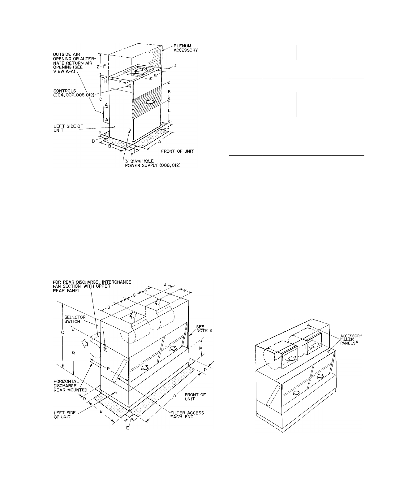
NOTES
Certified dimension drawings available upon request
1
Minimum required clearance at back and right side of
2
unit is zero Clearance above and at left of unit depends
on space required for accessory plenum, ductwork, con
denser piping, accessory heater piping, condensate drain
line power wiring, and access to unit control center
Clearance required at front of unit for service access and
free return airflow is 2 feet
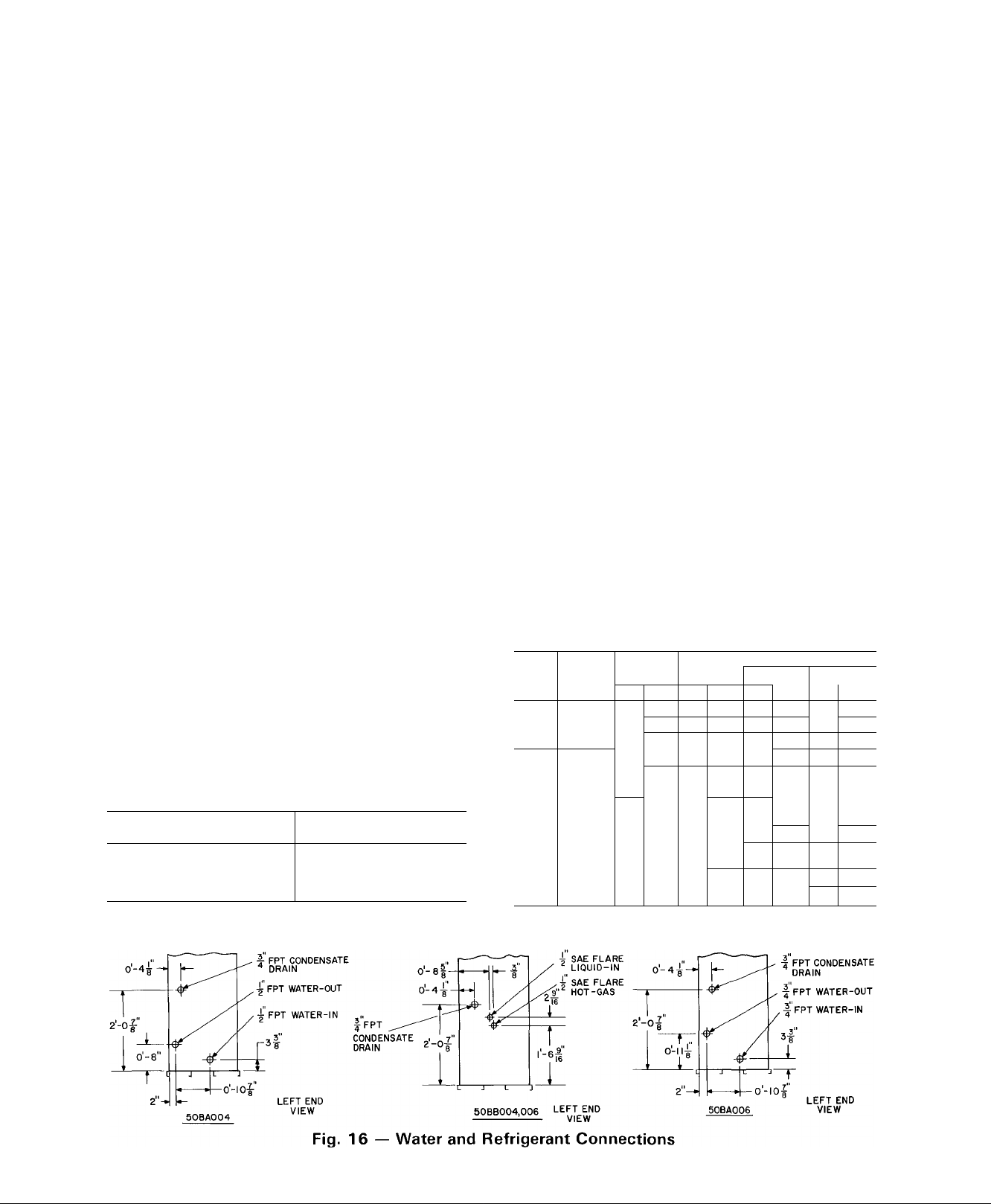
Water and refrigerant connections for Unit Sizes 50BA,
BB004 thru 01 2 are located on the left side of unit See
Fig 1 6 for connection details
DIMENSIONS (ft-in )
004
3- 2-5/16
1-10-7/8
1 5- 3-7/8
See Note 2
1- 4-7/16
1-1-1/8
1-0-1/2 0-10-5/8
0- 2
0-10
1- 3-9/16 1-4
006
1-3
0 3/4
008,
012
4-0
2- 6-1/8
6-5
1-0
2-0
1- 7-3/8
1- 5-1/4
0- 1-1/4
0-11-7/8
1-11-1/4
2- 5-3/8
3-6
0-3
1- 0-1/2
i
ELOOR
-v^
*ALTERNATE RETURN AIR OR
OUTDOOR AIR INLET
UNITS 50BA,BB016 AND 024
OPTIONAL TOP HORIZONTAL DISCHARGE
(D
ACCESS AREA
AIRFLOW
0
‘For optional top-mounted horizontal discharge, use
accessory filler panel package as shown See instal
lation instructions in filler panel package
■Fig. 1 — Unit Dimensions
2
Page 3
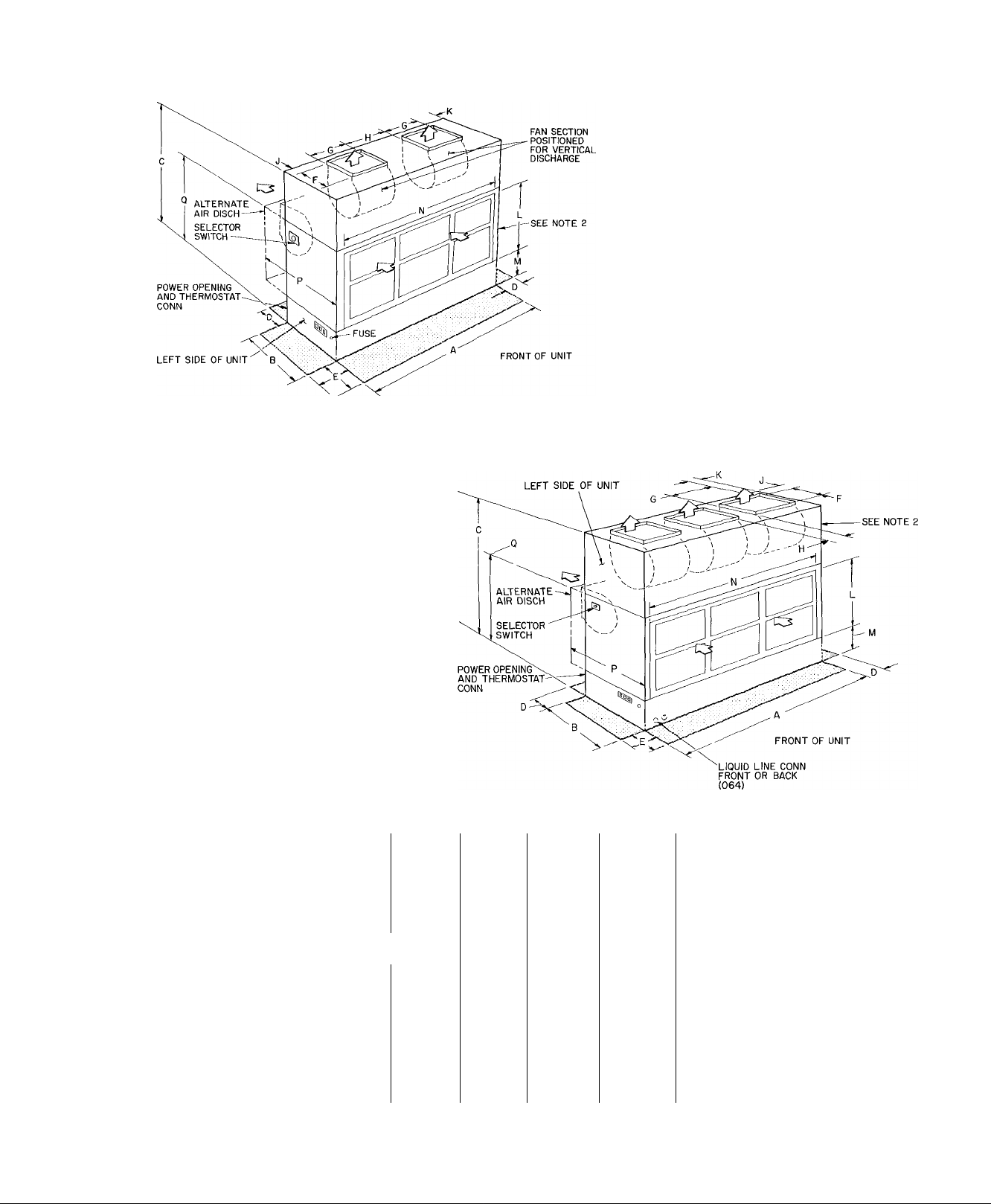
UNITS 50BA,BB028,034 AND 044
NOTES
1 Certified dimension drawings available on
request
2 Water and refrigerant connections for Unit Sizes
50BA,BB016 thru 064 are located on right side of
unit See Fig 1 6 for connection details
UNITS 50BA,BB054 AND 064
ACCESS AREA
AIRFLOW
[)
DIMENSIONS (ft-in
'■ ——
^10- g^3/g'
8- 0-1/8 8-10
2-0 2- 0
1-0
1- 8-7/8 1- 8-7/8
1- 8-7/8 1- 8-7/8
0- 2-3/a
3- 2-1/4
2- 1-1/8
7- 4-1/4 10- 0
'”o-3
2- 2-1/2
6- 4-5/8
. .. ...
- —-
054 064
1_-
3-10-1/4 3-10-1/4
9-9 10-1
3-0 3-0
3-0
3-10 4-9 4-9
1-0 3-0”
1- 8-7/8 1- 8-7/8
1- 8-7/8 1- 8-7/8
1- 5-5/8 1- 5-5/8
^ 0-3"^ 0-3
2- 2-1/2 2- 6-1/8
io-0 ^To-0
6- 4-5/8
UNIT
50BA.BB
A
B
C
D
E ~
F
G 1- 5-1/4
H
J
K
L
M
N
P
— ..—
016,024 028,034 044
" 6-8 7- 9-1/4
2- 5-1/4 2-11-1/4 3-10-1/4
6-10-1/2
2-0
. 3_Q
1- 7-1/4
1- 4-1/8 1- 7-7/8 2- 7-1/2
0- 1-5/8
1-7 1-4 2- 2-5/8 1- 2-1/4 1- 2-1/4
—
1-8
—
4- 4-5/8 5- 4-1/8
Q 4-1 1-1/2 5- 7-1/4 6- 3-5/8 7- 7-1/4 7- 7-1/4
"lol el/s'
6- 4-5/8
■Fig. 1 — Unit Dinrensions (cont)
3
Page 4
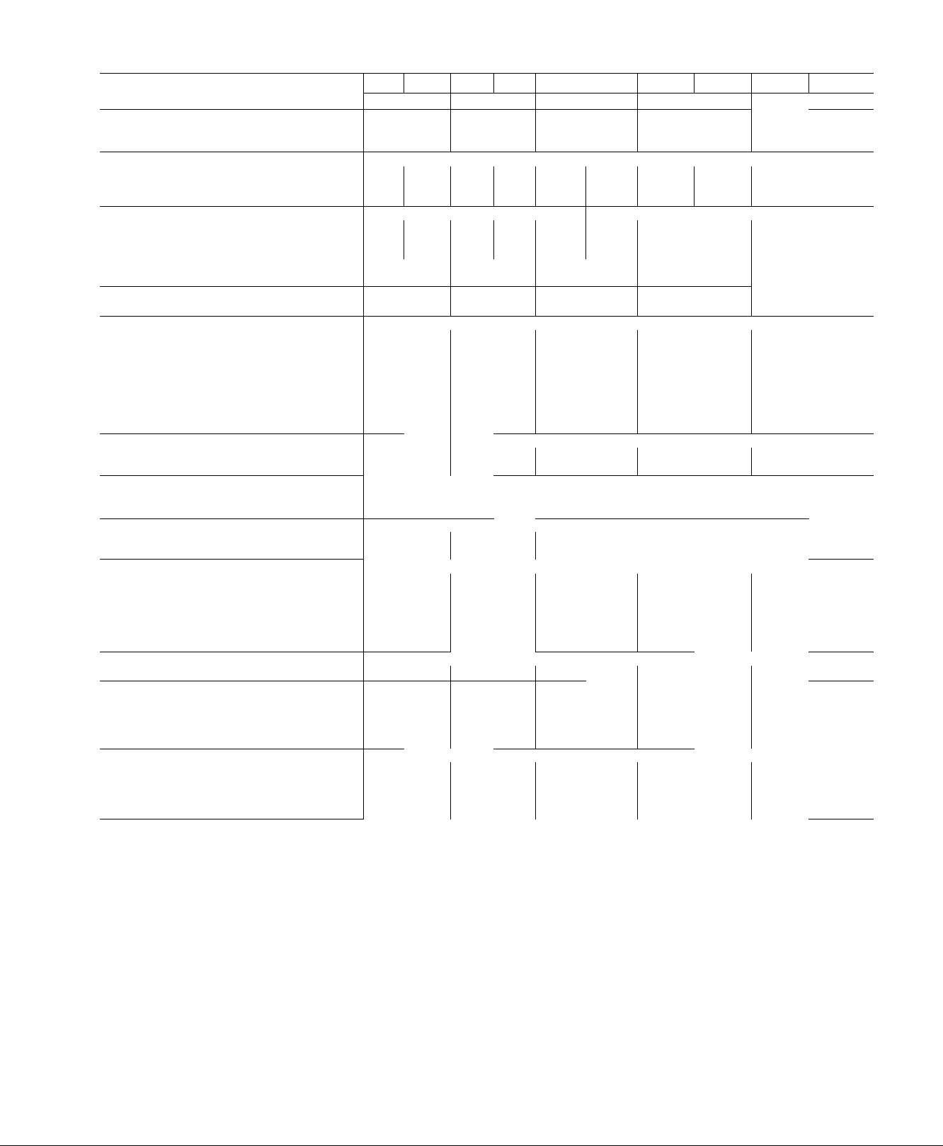
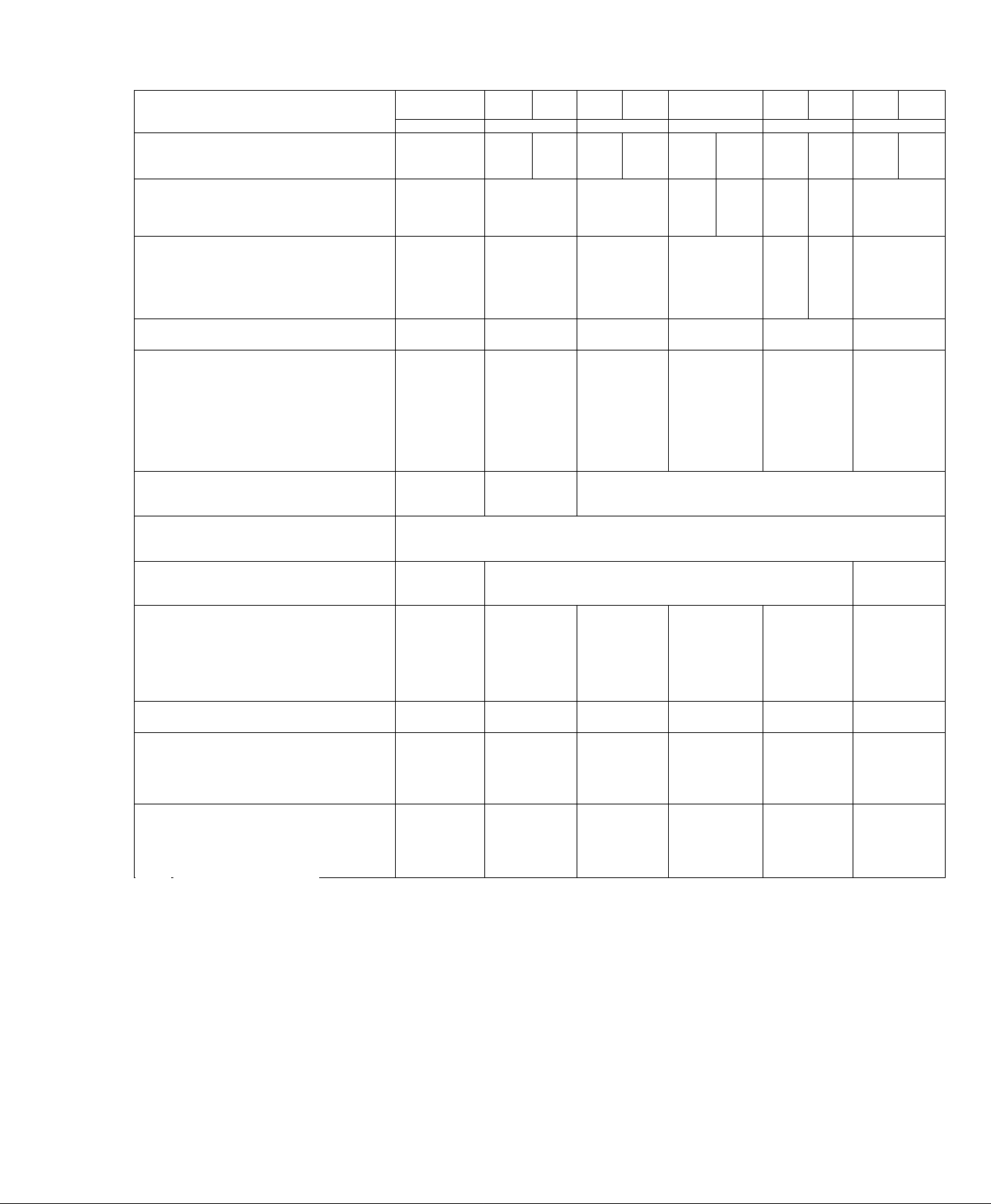
Table 1 — Physical Data
MODEL 50
OPERATING WEIGHT (lbs)
Base Unit
Discharge Plenum
OPERATING CHARGE (lbs) Refrigerant 22
System 1
System 2
System 3
COMPRESSOR — TYPE 06
System 1
System 2
System 3
No of Unloading Cylinders
No of Capacity Steps
CONDENSER (BA Only)
No. . Type
INDOOR FAN
Nominal Cfm
Standard Fan Speed Range (Rpm)
Maximum Allowable Rpm 1100 1100
No. of Belts . Fan Pulley PD (in )
Motor Pulley PDR (in )
Nom Hp Std...Frame Size 1/3 48
INDOOR COIL
No of Rows . Fins/in
Total Face Area (sq ft)
RETURN AIR FILTERS
No. ...Size (in.)
CONDENSER CONNECTIONS (BA Only)
Water Inlet — Manifolded
Water Outlet — Manifolded
REFRIGERANT CONNECTIONS (BB Only)
„ ^ - Hot Gas Line
System 1 Liquid Line
_ _ Hot Gas Line
System 2 Liquid Line
_ ^ _ Hot Gas Line
Systems Liquid Line
CONDENSATE CONNECTION
Condensate Drain
ACCESSORY HEATING COIL
Hot Water t , r- a /
„ Rows...Fins/in
HEATING COILS CONNECTIONS
Alt...Frame Size
Alt.. Frame Size
Rows ..Fins/in
Total Face Area (sq ft)
Total Face Area (sq ft)
Inlet
Hot Water r\ ^
Outlet
Outlet
BA BB
004
390 330 427
25
3 5
— —
—
Welded Hermetic, 3450 Rpm
M34 M34
—
— — —
0 0 0
1
1
TT
1200 2000
512-782
1 64
1 9-2 9 2 4-3 4
3/4 56 1
2
13 9
50
FPT 3/4
1/2
1/2 FPT 3/4 FPT
1/2 FI 1/2 FI
1/2 FI 1/2 FI
_
FPT 3/4
3/4
1
1~5
5 0 50
—
— —
1 7/8
1
7/8
1
7/8
1
7/8
2
—
—
2 16x25x1
BA
BB BA
006 008
360
25 140
46
—
—
P53
— — — — — —
1
TT
Adjustable, Belt-Driven Centrifugal; 1750 Rpm Motor
647-915
1
64
3/4 56
56
3 13 9
50
....... i
FPT
FPT
1
1 5
—
1
7/8
1
7/8 1
1
7/8 1
1
7/8
770
2 5 10
__
P67 P77
__
— —
—
— — — —
Copper Tubes, Aluminum Fins
Factory-Supplied Throwaway Type
......
BB
710
7
—
DA818
1
1 TT
3000
495-700 600-850
1100
1 8 5
2 4-3 4 2 4-3 4
1
56
145T
2
182T
3
3 12 1
7 3 8 5
4 16x20x1
.
Size (in ) . Type
1
1 FPT
Size (in.)...Type
3/4
5/8 ODF 5/8
3/4 FPT 3/4
2 14
1
No
1 1-1/4
1
(See Note 4)
FPT
ODF
_
—
—
—
Size (in ) Type
60
14
6 9
Size (in.) MPT
1-1/4
1-1/4
1-1/4
BA
950
10
—
—
Serviceable Hermetic, 1750 Rpm
DB724 DB824 DD337
....
.J...
BB
012
890
140
8
— —
—
2 2
2
1 TT
4000
1100
1
70
2 45T
3 182T 3
3 12 1
1 FPT
FPT
ODF
3/4
ODF
FPT 1
2 14
60 15 7
1 14
6 9
1 1-1/4 2
1-1/4 2
1
1-1/4 1
1
1-1/4 1
1
BA
1414
24
—
1 SC
568-720
1 11 4
3 7-4 7
2 145T
5 184T
3 106
3 16x25x2
3 20x25x2
2
1-1/8 ODM
5/8
2 11 3
1
BB
016
1221
140
15
— -
-
DD537
2
6000
1100
182T
16 9
FPT
FPT
i
ODM
FPT
14
144
1-1/2
1-1/2
1-1/4
1-1/4
Step 3 — Provide unit support.
Refer to Fig. I — Dimensions, and Table 1 —
Physical Data for unit size and weight.
Construct a stand or frame of I-beams or angle
iron that supports unit adequately, if desired. The
floor and floor joists of existing buildings may
require reinforcement; follow applicable codes.
Step 4 — Rig and place unit.
Provide space around unit for service, filter access
and overhead clearance as indicated in Fig. 1.
Move and store unit in upright position.
50BA,BB004 AND 006 — Use rollers under ship
ping rails. Unit may be moved by hand truck on any
side. Do not remove shipping rails until unit is in
final position.
50BA008 THRU 064 — Use slings with spacer under
base skid to prevent panel damage when using hoist.
Raise base skid on blocks and remove bolts. On 028
thru 064 units, unbolt fan section from skid.
Units as shipped are adequately dampened
against vibration. If additional dampening is de
sired, place sponge rubber, rubber mat or fiberglass
roof insulation between floor and base of unit or
install vibration isolators.
Page 5
MODEL 50
OPERATING WEIGHTlibir~~~~~
Base Unit
Discharge Plenum
OPERATING CHARGE (lbs)
System 1
System 2
System 3
DUMPHESSOR — TYPE 06
System 1
System 2
System 3
No. of Unloading Cylinders
No of Capacity Steps
CONDENSER (BA Onl^
No. . Type
llML/<^UK hAN "
...................................................
Nominal Cfm
Standard Fan Speed Range (Rpm)
Maximum Allowable Rpm
No of Belts...Fan Pulley PD (in )
Motor Pulley PDR (in.)
Norn HP Std...Frame Size
Alt .Frame Size
Alt. .Frame Size
INDOOR COIL
No. of Rows. .Fins/in.
Total Face Area (sq ft)
RETURN AIR FILTERS
No. ...Size (in )
CONDENSER CONNECTIONS (B^Onlv)
Water Inlet - Manifolded
Water Outlet — Manifolded
refrigerant CONNECTIONsTBB^iii^
System 1 Line
System 2 Line
System 3 Line
Liquid Line
Liquid Line
Liquid Line
CONDENSATE CONNECTION ~~~ ~-
Condensate Drain
ACCESSORY HEATING COIL
Hot Water Fins/in.
Total Face Area (sq ft)
Steam Flows. Fins/in.
_ Total Face Area (sq ft)
HEAIING COIL CONNECTIONS
Hot Water
Steam
FPT
— Female Pipe Thread
Hp
— Horsepower
MPT
— Male Pipe Thread
PD
— Pitch Diameter
PDR
— Pitch Diameter Range
SC
— Shell and Coil
ST
— Shell and Tube
— Tube in Tube
Outlet
Outlet
Table 1 — Physical Data (cont)
BA 1 BB
024
i
1894 i 1464
140
17 1 7
17 1 7
DA724I DA824
DA724I DA824
0
2
2 SC 2 SC 2 SC 2 SC
8000
700-875
1100
2 100
4 0-5 0
3 182T
5 182T
4 106
180
3 16x25x2 1 6 25x20x2 1 11 oc on 9 1 20x25x2
3 20x25x2 I 2 16x20x2 1 '' | 5.16x25x2
2-1/2 FPT
2-1/2 FPT
7/8 ODM
5/8 ODM
7/8 ODM
5/8 ODM
1 FPT 1-1/4 MPT
2 113
15 7
1 14
14 4
2 1-1/2
2 1-1/2
1 1-1/4
1 1-1/4
NOTES
1 50BB008 has serviceable hermetic 1750 rpm compressor
2 Operating charge for 50BB units does not include charge for remote air
cooled condenser or connecting pipe All 50BB units are shipped with a
holding charge Operating charge values are approximate See installa
tion instructions
3 Fan motor pulleys on 50BA,BB044,054 and 064 are fixed-pitch type
4 Field-supplied 2-in filters will fit
5 Motors and drives other than those furnished with unit must be purchased
locally Installation may require field modification Contact your local
Carrier representative
BA BB
028
2491
2397
24 1 15
17 112
DA3371DA537
DA7241DA824
0
2
Adjustable
10,000
605-750
1100
2 12 4
4 3-5 3
5 184T
7-1/2 213T
10 215T
4 89
22 6
BA
BB BA 1 BB
034
2598 2430 3800
Refrige
24 1 15
24 1 15
Serviceable Herr
DA337I DA537
DA337I DA537
0
2
;, Belt-Driven Ce
12,000
685-845
1100
2 11 0
4 3-5 3
5 184T
7-1/2 213T
10 ..215T
Copper Tubes — Aluminum Fins
Factory-Supplied Throwaway Type
Size (in ) ..Type
1-1/2, 2 FPTI 2,2 FPT I 3 FPT 1 3 FPT
1-1/2, 2 FPT 2,2 FPT 3 FPT 3 FPT
Size (in
1-1/8 ODS
5/8 ODS
7/8 ODS
5/8 ODS
1-1/8 ODS
5/8 ODS
1-1/8 ODS
5/8 ODS
Size (in
1-1/4 MPT
2 14
11 7
I 14
II 4
2 14
11 7
I 14
II 4
No .. Siz
2 1-1/2
2 1-1/2
2 1-1/2
2 1-1/4
2 1-1/2
2 1-1/2
2 1-1/2
2 1-1/4
044 054
3100
rant 22
24
24
17
netic, 1750 Rpm
DA3371DA537
DA337 DA537
DA7241 DA824
0
3
ntrifugal; 1750 R
16,000
627,672,717
1100
2 154
5 6,6 0,6 4
7-1/2 213T
10 215T
489 j 490 j 490 | 4 10 6
26.9 36 5 46.3 46.3
4100
15
15
11
DA337
DA337
DA337
pm Motor
.)...Type
1-1/8 ODM
5/8 ODM
1-1/8 ODM
5/8 ODM
7/8 ODM
5/8 ODM
.). .Type
1-1/4 MPT 1-1/2 MPT 1-1/2 MPT
2 113
35 0
1 10
32 6
s (in ) MPT
3 1-1/2
3 1-1/2
2 2-1/2
2 1-1/2
BA
BB
3300 4404
29
29
29
DA537
DA537
DA537
)
2 SC
20,000
650,695,762
1100
2 154
5 8,6 2,6 8
10 215T
15 254T
1-1/8 ODM
5/8 ODM
1-1/8 ODM
5/8 ODM
1-1/8 ODM
5/8 ODM
2 113
44 8
1 10
38 8
3 1-1/2
3 1-1/2
2 2-1/2
2 1-1/2
15
15
15
BA
BB
064
3550
52 1 25
52 1 25
EA275!EA275
E5275i E5275
4
6
2 ST
24,000
785,828,895
1100
2 154
7 0,7 4,8 0
15 254T
3 FPT
3 MPT
1-3/8 ODM
7/8 ODM
1-3/8 ODM
7/8 ODM
2 113
44 8
1 10
38 8
3 1-1/2
3 1-1/2
2 2-1/2
2 1-1/2
Page 6
isBKggggsas^iKssasìgagsasBgagaagMi
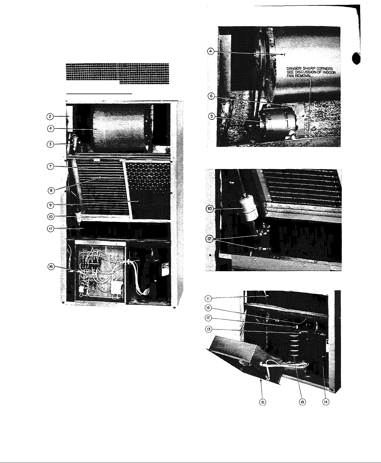
INDOOR AIR FAN DETAIL
BASE UNIT GENERAL VIEW
1 — Accessory Plenum
2 — Selector Switch and Thermostat
3 — Thermostatic Expansion Valve
4 — Indoor Air Fan
5 — Indoor Air Fan Motor
6 — Indoor Air Fan Motor Mounting Bracket
7 — Evaporator
8 — Thermostat Sensing Bulb
9 — Return Air Filter
10 — Refrigerant Filter-Drier
11 — Water Regulating Valve Fitting on Refrigerant Liquid Line (50BA)
12 — Low-Pressure Cutout Switch (50BA,BB006 only)
13 — Suction Pressure Gage Connection
14 — Compressor
15 — Discharge Pressure Gage Connection (50BA)
16 — Control Box
17 — Service Valves, Suction and Discharge, with Gage connections (50BB)
18 — Water-Cooled Condenser (50BA)
Fig. 2 — Base Unit Interior Details (50BA,BB004,006,008 and 012)
SERVICE VALVE DETAILS (50BB)
COMPRESSOR COMPARTMENT
Page 7
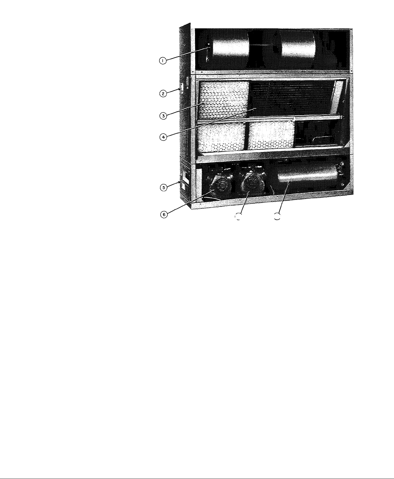
LEGEND FOR
50BA024 UNIT
1 — Indoor Air Fan
2 — Selector Switch
3 “ Return Air Filters
4 — Evaporator Coil
5 — Control Box
6 ^ Compressor No 1
7 — Compressor No 2
8 — Condensers
[7J (81
Fig. 3 — Base Unit Interior Details (50BA024 Unit Shown)
Step 5 — Install accessory plenum if supplied.
On unit Sizes 004 thru 024, holes in the unit top
panel match holes in plenum. Use screws (shipped
in cloth bag taped inside plenum) to attach plenum
to unit top. See Fig. 1 and 2.
Step 6 — Position fan section as desired.
UNIT SIZES 50BA,BB004 THRU 024 are shipped
for vertical discharge. To set up these units for hori
zontal discharge, separately purchased accessory
filler panels must be field installed (see Fig. 1).
To set up unit Sizes 50BA,BB016 and 024 for
backmounted horizontal discharge (Fig. 1), proceed
as follows;
1. Remove;
a. Rear fan-section panel.
b. Upper rear coil-section panel.
c. Power connections from indoor fan motor.
d. Corner bolts holding fan section to coil
section.
2. Remove fan section and rotate it 180° lengthwise
so that motor is on left side of unit.
3. Place fan section on rear of coil section and
refasten.
4. Replace indoor fan motor power connections.
5. Adjust the following items per Installation
Step 8;
a. Shaft alignment.
b. Fan wheel position.
c. Pulleys.
d. Fan belt.
6. Replace panels as follows;
a. Upper rear coil-section panel on top of coil
section and fasten.
b. Rear fan-section panel on top of fan section
and fasten.
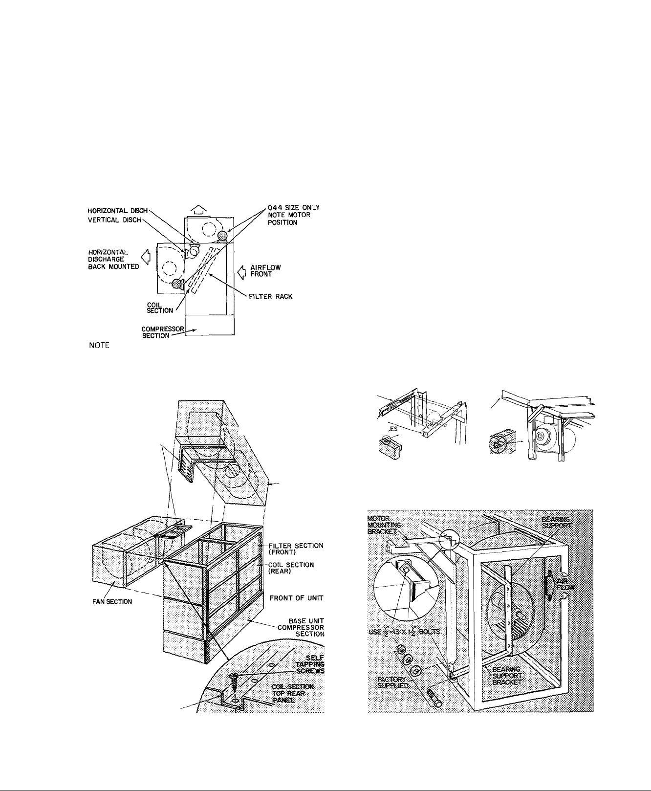
UNIT SIZES 50BA,BB028 THRU 064 are shipped
in sections as noted previously. They can be field
assembled for either vertical or horizontal discharge.
NOTE; Fan section panels may be removed for
easier lifting and to facilitate motor installation.
To set up Sizes 50BA,BB028 thru 064 for horizon
tal discharge (Fig. 4 and 5), proceed as follows;
1. Remove;
a. Upper rear and end panels of coil section.
b. End panels on fan section.
c. Fasteners holding lower rear edge of fan
panel.
Page 8
2.
Lift and position fan section on rear of coil section
(Fig. 4). Secure with fasteners provided.
3.
Install the following per Installation Step 7:
a. Motor mounting frame angles.
b. Motor on plate assembly.
c. Motor-plate assembly on frame angles.
d. Balance of drive package components.
4.
Adjust the following per Installation Step 8:
a. Shaft alignment.
b. Fan wheel position.
c. Pulleys.
d. Fan belts.
VERTICAL DISCH
TOP MOUNTED
Motor pulley on left side of unit — vertical discharge
Motor pulley on right side of unit — horizontal discharge
Fig. 4 — Fan and Motor Arrangements
50BA,BB028,034,044,054,064
REAR HORIZONTAL FAN
AND VERTICAL FAN
DISCHARGE SOBA.BB
028,034,044,054
MOTOR MOUNTING
BRACKETS (INSTALL
AFTER MOUNTING
fan SECTION)
\ AND 064
FAN SECTION
5. Replace panels as follows:
a. Rear coil section panel on top of coil section.
Rear holes will overlap fan section top panel.
Fasten, using hole vacated in Step Ic (see
Fig. 5).
b. All end panels.
NOTE; On Size 044 units, motor mounting channels
are factory installed and no angles, plates or
fasteners are necessary. In this position, the fan
motor is located on right side within fan section.
To set up Sizes 50BA,BB028 thru 064 for vertical
air discharge (Fig. 4 and 5):
1. Remove:
a. Front, rear and end panels of fan section.
Upper-rear and end panels of coil section.
b.
Filters from coil section.
c.
Fasteners holding filter frame top. Push frame
d.
out and away from coil section frame (on 028
and 034 units only).
2. Lift up and position fan section on coil section
(Fig. 5).
3. Fasten fan-section frame to coil-section frame
with fasteners provided, then (on 028 and 034
units) reposition and fasten the filter frame
moved in Step Id.
4. Install the following per Installation Step 7;
a. Motor mounting frame angles.
b. Motor on motor-plate assembly.
c. Motor-plate assembly on frame angles.
d. Balance of drive package components.
MOTOR MOUNTING
ANGLES
FAN SECTION
ADJUSTING
SCREW HOI
Fig. 6 — 028 and 034
Horizontal Fan Motor
Mounting Angles
FRAME
Fig. 7 — 054 and 064
Vertical Fan Motor
Mounting Angles
NO MOTOR MOUNTING
BRACKET USED WITH
044 SIZE UNIT
THREE FANS ON 054 AND
064 UNITS
REAR PANEL FAN SECTION
Fig. 5 — Fan Section Mounting
(50BA,BB028-064)
I
Fig. 8 — Fan Motor Mounting Detail
(50BA,BB054 and 064)
Page 9

FAN MOTOR
50BA,BB
028,034
MOUNTING
HOLES
PLATES
FOR
ADJUSTING
SCREWS
WELD
NUT
50BA,
BB044
50BA,BB
054,064
Fig. 9 — Motor Mounting
NOTE: On 044 units, motor mounting plate and
channels are factory installed within fan section. No
angle frame plates or fasteners are necessary. In this
position, motor is on right side of fan section.
5. Adjust the following per Installation Step 8:
a. Fan wheel alignment.
b. Shaft alignment.
c. Pulleys.
d. Fan belts.
SUPPORT CHANNEL
WELD NUT-
6. Replace panels as follows:
a. Rear coil-section panels, front and rear fan-
section panels.
b. All end panels.
Step 7 — Install fan motor.
This step applies to unit Sizes 50BA,BB028, 034,
054 and 064. Install items after fan-section frame
has'been placed in position on coil section.
NOTE: Place plywood over evaporator coil to pre
vent damage while installing motor and mounts.
To install motor:
1. Fasten motor mounting angle bracket to fan sec
tion. Use Fig. 4 or 5 for position reference and
Fig. 6, 7 and 8 for assembly guidance. Be sure
that lips of angle brackets are around fan-section
frame and that slots for motor mounting plate
face each other.
On Sizes 50BA,BB054 and 064, align bearing
support bracket holes with holes in motor
mounting bracket. Fasten with bolts, flat
washers, lock washers and nuts as shown in
Fig. 8.
2. Position motor on motor plate (Fig. 9) and fasten
with fasteners provided.
3. Fift motor-plate assembly and slide into motor
mounting angles as shown in Fig. 6. Plate fits into
angle slots. On vertical mounts, the motor-frame
assembly may be lowered to the bottom of the
support angle channels.
4. Assemble and install motor adjusting screws as
shown in Fig. 10. Drive roll pins into screws to
prevent screws from backing out during motor
position adjustment.
5. Adjust motor position. Fasten motor mounting
plate to mounting angles.
#
MOTOR
ADJUSTING
SCREW
Fig. 10 — Assembled Fan Motor
MOTOR
SUPPORT
ANGLE
Adjusting Screw
MOTOR
SUPPORT
CHANNEL
Table 2 — Alternate Fan Motors and Drives
UNIT
50BA,
BB
004 56 3/4 17.5 15.7
006 56 1
008,
012
016,
024
028,
034
044
054,
064
•Range of motor sizes unit will accept
NOTE Motors and drives other than those furnished with unit
must be purchased locally
NEMA
FRAME
SIZE*
184, 56, 145T 2
182T, 213
184, 56, 145T 2 11 8
213, 182T 3 11 8 8 4 1
184T, 215 5 11.8
182T, 213
184T, 215
254U, 213T
256U, 21 5T
213T
21 5T
21 3T 7-1/2
21 5T 10
254T 15
CENTER LINE
HP
7-1/2 33 3
7-1/2
DIST>
___
Max Min
17 1 15.4
102 6 8
102
3
34 4
3
34 4 28 8
5
33 3 29 8
10
14 3
14.3
10
33 5
33 5 29 0 1-7/16
33.5 29.0
(ir
XNCE
D..„„
10 1
10.1
6 8
8.4
28 8
29 8
29 0
FAfVI
SHAFT
DIAM
(in )
1/2
5/8
3/4
94
1-3/16
1-7/16
Page 10

Step 8 — Align fan shaft and wheel.
HORIZONTAL WHEEL CENTERING — All
wheels must be horizontally centered between the
inside edges of their fan scroll venturis (Eig. 11).
VENTURI
Fig. 11 — Horizontal Wheel Centering
WHEEL
/SCROLL
MUST BE EQUAL ALL AROUND
Adjust as follows:
Unit Sizes 50BA,BBQ04 thru 024
1. Loosen setscrews holding wheel support to shaft
(Eig. 12).
2. Center the wheel by sliding it horizontally.
3. Retighten setscrews.
CONCENTRIC ALIGNMENT Shaft and
wheels must be concentrically centered with the
venturi or air inlet of the fan housing (Fig. 13).
Unit Sizes 50BA,BB004 thru 024 — Shaft bearings
are supported by spider (Fig. 14). If shaft and wheels
are concentrically misaligned from shipping shock,
it is possible to rebend spider arms to original posi
tions. Replace the spider if it has been extensively
damaged by shipping shock.
Unit Sizes 50BA'BBQ28 thru 064
1. Loosen fan wheel locking clamps on each side
of fan support (Fig. 12).
2. Center the wheel by sliding it horizontally.
3. Retighten locking clamp bolts to torque speci
fied in Table 3.
Table 3 — Torque Requirements
BOLT SIZE (in.)
5/16
7/16
FAN CLAMP BOLT
RECOMMENDED TORQUE (Ib-ft)
15-18
30-35
VENTURI
LOCKING COLLAR
SHAFT
Fig. 14 — Fan Shaft Bearings — 004,006,
008,012,016,024
10
Page 11

Unit Sizes 5QBA028 thru 064 — Bearings are bolted
to an angle support fastened to fan scroll (Fig. 15).
To correct shaft and wheel concentric misalignment:
1. Loosen bearing support bolts and shim or move
as required.
2. Retighten bearing support bolts.
HORIZONTAL SHAFT ALIGNMENT (All units)
— If the shaft has moved and all wheels are off
horizontal center, recenter the shaft as follows:
1. Loosen the setscrews holding bearing locking
collar at each end of shaft (Fig. 14 or 15).
2. Slide shaft and wheel assembly horizontally until
wheels are horizontally centered (Fig. 11).
3. Slide the bearing locking collars against the bear
ing race and turn in direction of shaft rotation
until tight.
4. Retighten locking collar setscrews.
CUTOFF CLEARANCE (Unit Sizes 044, 054 and
064) — After centering and aligning the fan wheel,
loosen cutoff sheet (Fig. 13), adjust for 1-1/4 in.
clearance as shown and then tighten securely.
FAN, PULLEY AND BELT ADJUSTMENT
Refer to the Service section entitled Indoor-Air
Fan Adjustment.
PILLOW BLOCK
FAN SHAFT
BEARING.
SHAFT EXTENSION
LONGER ON
ONE END TO
ACCOMMODATE
DRIVE PULLEY
BEARING LOCKING
COLLAR 2 SET SCREWS
'SHIM IF NECESSARY
Fig. 15 — Horizontal Shaft Alignment
Step 9 — Install heating coil if supplied.
'HOLLOW SHAFT
3 FANS ON 028-064
On 50BA,BB004 and 006 units, any water or
steam heating coil must be installed thru the back
of the unit as described in the Installation Instruc
tions shipped with the accessory coil.
Step 10 — Install supply air (evaporator)
ductwork.
Connect supply ducts to flanges on air supply
opening (Fig. 1), using a flexible connection.
Attach ductwork to building structure and insu
late with fiberglass and vapor barrier to prevent
sound transmission and vapor condensation.
Weatherproof external ductwork, joints and
openings with flashing and mastic in accordance
with applicable codes.
Ducts passing thru an unconditioned space must
be insulated and covered with a vapor barrier.
Step 11 — Install return air ductwork (004 —
012 units).
The unit back panel is stamped to indicate alter
nate return air (or outdoor air inlet) opening as
indicated in Fig. 1.
1. Cut out the alternate return air opening as
required.
2. Attach a 1-in. flange to unit back panel or attach
a flanged, flexible duct connection directly to
unit as desired.
If an outdoor makeup air damper is to be in
stalled, attach it directly to unit back panel and
install flexible connection between damper
assembly and remaining ductwork.
Use accepted ductwork installation procedures.
Follow all applicable codes.
3. Restrict or completely blank off the standard
return air opening with a field-fabricated filler
panel. This panel must be removable for service
access. Refer to Service section entitled Return
Air Grille Removal as required.
Step 12 — Check return-air filters.
Be sure filters shipped with unit are the correct
size (see Table 1). Never operate unit without return-
air filters in place.
Step 13 — Check compressor spring mounts
(50BB008 and 50BA,BB012 thru 064).
The compressors are held rigid in shipment by
bolts extending thru a washer, grommet and com
pressor foot into a weld nut (for 064 unit, see para
graph below).
Loosen each bolt (4 per compressor) until com
pressor floats freely on springs. Then retighten bolts
until there is slight pressure on the neoprene gasket.
This will steady the compressor and prevent
start and stop rocking.
The 50BA,BB064 units are shipped with 4 special
flanged washers and neoprene grommets in a cloth
bag tied to the compressor. Remove the compressor
hold-down bolts. Then install the neoprene
grommets between the compressor feet and the
special washers. Reinstall the hold-down bolts and
tighten until there is slight pressure on the
grommets.
The compressors have reversible oil pumps that
operate in either direction; therefore the direction
of rotation need not be checked.
NOTE: Do not loosen bolts on 50BA008
compressor.
Step 14 — Make condenser connections.
WATER-COOLED (50BA) UNITS ^ GENERAL
— Condensers have water inlet and outlet connec
tions as shown in Fig. 16. Piping arrangements for
city, waste or recirculating water are shown in
Fig. 17 thru 24.
11
Page 12
WATER-COOLED UNITS, SIZE 50BA004
THRU 012 — Connect condenser water supply and
return lines as indicated in Fig. 16 and 17. When
connecting water lines, hold the condenser inlet and
outlet stubs firmly with a wrench at the FPT hex
fitting to prevent twisting. Do not use water lines
smaller than connection sizes shown in Fig. 17.
Observe all applicable plumbing and sanitary codes.
To assemble Carrier Compatible Fittings:
1. Cut tubing to length with tube cutter and remove
burrs.
2. Mark required insertion depth on tube (1-1/4 in.
for 5/8- and 3/4-in. OD tubing).
3. Remove plug from fitting and loosen nut one
turn.
4. Position and insert tube into fitting. Bottom
tube past depth mark.
5. Leave nuts on condenser end of tubing. Loosen
and purge one line at a time, using holding
charge in base unit.
6. Tighten nuts to stop on unit fitting collar.
7. Open all service valves.
Make sweat connections as follows:
1. Clean tube; then remove plug and nut from
fitting.
2. Remove O-ring from inside fitting with bent pin.
3. Wrap entire valve with wet rag.
4. Bottom tube in fitting and apply low temperature
solder, such as Allstate 430.
If specified, install field-supplied water-regulating
valve in water supply line outside cabinet as
follows:
1. Route the regulating valve capillary with its flare
nut to the fitting on refrigerant liquid line (Fig. 2),
using any convenient unused opening on side of
unit. Use a grommet in unit panel to prevent
chafing of capillary.
Table 4 — Maximum Water-Side
Working Pressure
UNIT SIZE 50BA
004,006,008,012 450 psig
016 550 psig
024,028,034,044,054, 150 psig*
064 250 psig
*550 psig if factory-installed dresser adapters are removed and
field-fabricated manifold is installed
MAXIMUM WORKING
PRESSURE
2. Remove cap from liquid line fitting.
3. Remove cotter pin taped to liquid line near
fitting. Insert pin, split end first, into water
regulating valve flare nut.
4. Connect flare nut to fitting. Round end of cotter
pin will depress core of fitting. The opened
fitting allows refrigerant pressure to act on water
regulating valve. Tighten flare nut to prevent
leakage.
The fitting automatically seals (closes) when flare
nut is removed; a slight amount of refrigerant is lost
each time, however. Do not lose cotter pin.
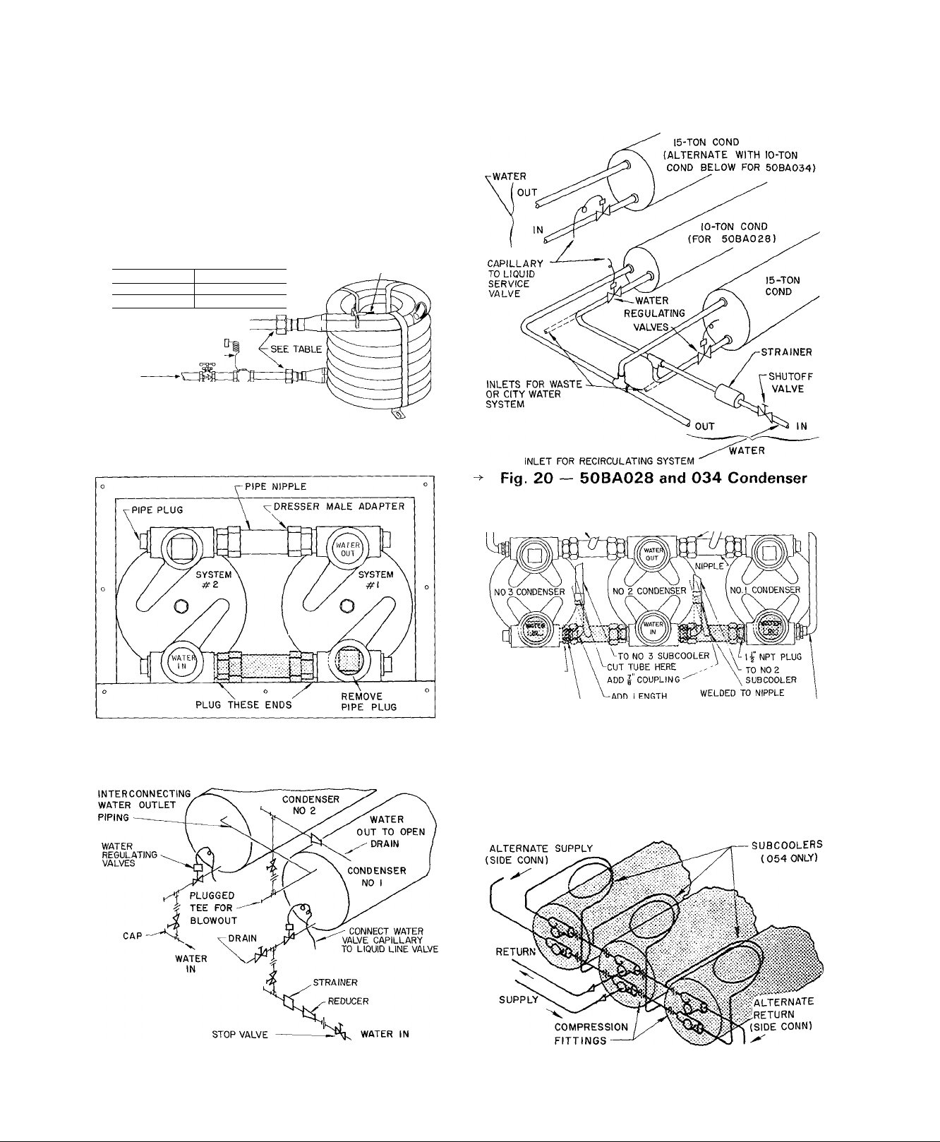
WATER-COOLED UNITS, SIZE 016 THRU 064
— Connect condenser water supply and return lines
as indicated in Fig. 16. Unit Size 50BA024, 044, 054
and 064 require field modification to condenser
piping when used on city or waste water. Refer to
Fig. 18, 21 and 24.
Install a water regulating valve on the inlet of each
condenser with any size unit used on waste or city
water (Fig. 19,20,22,23 and 24). Connect regulating
valve capillary to a back-seated liquid service valve.
Arrow on valve body must point in direction of
liquid flow. After connecting capillary, open
regulating valve one turn from back-seated position.
Adjust valve to maintain proper condensing
temperature.
Install a full size gate valve and strainer in water
supply line. Valve and strainer must be accessible.
See Table 4.
Table 5 — Recommended Line Sizes (in.)
(Condenserless Models)
UNIT
SYSTEM
50BB
004
006
008
012
016 —
024 1 & 2 5/8
028
034 1 & 2
044
054
064 1 & 2 7/8
HG — Hot Gas Line (OD
L — Liquid Line (OD in
—
—
—
1 & 2 5/8 1-1/8 5/8 1-1/8
1,2,3
CONN
SIZES*
L
1/2
1/2 1/2 1/2
1/2
5/8 7/8 5/8
-
5/8
5/8
1
5/8
2
5/8
5/8
3
5/8 1-1/8 5/8 1-1/8
L HG
HG
1/2
1/2
1/2
7/8
5/8
1-1/8
5/8
7/8
1-1/8 5/8 1-1/8
7/8 5/8 7/8
1-1/8 5/8 1-1/8
7/8 5/8 7/8
7/8
1-3/8
in )
)
LENGTH OF LINE
20
L HG L
1/2
1/2
1/2 7/8
7/8^
1/2 7/8
7/8
5/8 1-1/8 3/4 1-1/8
7/8
7/8 1-1/8
1-1/8
5/8
7/8
7/8 1-1/8
5/8 1-1/8 7/8
7/8 1-1/8 7/8
7/8 1-1/8
5/8 1-1/8
7/8 1-1/8
7/8 1-5/8
1-3/8
40
5/8 1/2 7/8
ï-i/8
*Sweat connections
5/8
1/2
7/8
7/8
7/8
7/8
7/8
7/8
7/8
60-80
1-3/8
1-1/8
1-3/8
1-1/8
1-3/8
1-3/8
1-1/8
1-3/8
1-5/8
HG
7/8
7/8
12
Page 13

2 DIA HOLE
FOR I "FPT COND
WATER INLET
(BA) CONN
50BA,BB008,0I2
W DIA KO FOR
f'oDF
LIQUID LINE
'dia hole for
|“fpt
CONDENSATE
CONN
2"DIA HOLES FOR
i"fpt cond water
OUTLET(BA)CONN
= HOT GAS
LINE (BB) :
LEFT END
VIEW
NOTE ■ ALL VIEWS ARE RIGHT END VIEWS EXCEPT AS INDICATED
(50BA, BB004 THRU 012 UNITS)
2 FPT water
OUTLET-
81/8" ;
t
' t
5 1/2"
---------------
"i-l'-9 1/2^
50BA0I6
T FPT
CONDENSATE
DRAIN CONN-
n
^
V.
-2 F PT
WATER
INLET
I 1/8 0 DM HOT
GAS CONN
50BB0I6
I" FPT
CONDENSATE
DRAIN CONN.
I ODM
LIQUID LINE
CONN
2 1/2" FPT
WATER OUTLET
2 1/2" FPT \
WATER INLET
HOT GAS
CONN.
7" ODS
8(028)
I^ODS
T
l"-5|-
FLOOR
LINE
50BB028 a034
50BA024
N
1 I
-T FPT
CONDENSATE
DRAIN CONN
-Ig ODS
/
■| ODS
<■2
16
HOT GAS
C0NN.(028
034)
LIQ LINE
C0NN.(028
034)
7/8 OD M HOT
GAS CONN.
4 3/4"
_L
S ODM
8
LIQ LINE
CONN.
2 FPT WATER
INLET-
FLOOR.
LINE
.2 FPT WATER OUTLET
1
pN
hi
1 V
4
50BA034
lEPT-“
CONDENSATE
DRAIN
CONN.
1^" FPT WATER INLET
FLOOR ^8
LINE
2
2'-2"-J
RIGHT END VIEW
50BA028
f
4
MOUNTING HOLES
2" FPT
WATER
INLET
50BA044,054
CONDENSATE
K..
(3 HOLES)
l-gODM
(50BB044
#
ONLY)
50BB044,054
MOUNTING HOLES
3"MPT WATER
I^MPT
'CONDENSATE
DRAIN CONN
Fig. 16 — Water and Refrigerant Connections (cont)
13
Page 14
ALL 50BB (AIR-COOLED) UNITS — Install air
cooled condenser in accordance with the installation
instructions provided with condenser. Connection
locations for liquid and hot gas service lines are
shown in Fig. 16. Recommended line sizes are given
in Table 5. Refer to Carrier System Design Manual,
Part 3, for standard refrigerant piping techniques.
Condenserless (50BB) units are shipped with a
holding charge. After refrigerant connections are
made, evacuate, leak test and charge system as
described in the Service section entitled. Charging
the System. Unit refrigerant operating charge is
listed in Table 1.
50BA004 1/2-in. FPT Conn,
50BA006
50BA008.012 1 -in FPT Conn
WATER
WATER
-—c
OUT
CONNECT TO
LIQUID SERVICE
VALVE GAGE PORT'
IN
WATER / /'WATER
SHUTOFF^ ^ REGULATING
VALVE
3/4-in. FPT Conn.
VALVE
Fig. 17 — Condenser Water Piping
(50BA004-012)
REMOVE SHADED FITTINGS
Fig. 18 — 50BA024 Condenser City Water
Piping Conversion
REFRIGERANT IN
Water Piping
/-FROM N0.3
SUBCOOLER
T'npt to
}"npt bushing
COUPLING
|"nPT-J"tUBE
A Remove shaded fittings
-^NOTE 50BA044 units same less subcoolers
1 Use one outlet for water discharge
2 Remove interconnecting nipples and "dresser” adapters on
inlet side of condensers
3 Remove 3-in plugs from no 1 and 3 condenser inlet headers
^FROM N0 2
\SUBCOOLER
----------------
' OfTuBE’ to no I subcooler (EXISTING)'
’’DRESSER” aFROM NO.I
adaptersn/v subcooler
Fig. 21 — Field Conversion to City or
Waste Water System (50BA044 and 054)
i
Fig. 19 — 50BA024 Typical Waste or
City Water Piping
Fig. 22 — Recirculating Water System Piping
(50BA044 and 054)
\A
Page 15

Step 15 — Install unit drain line.
Install a trapped condensate drain line at unit
drain connection (Fig. 16). The drain requires
standard pipe connected to condensate pan nipple
as shown in Table 6. Figure 26 shows proper trap
design.
Determine design negative static pressure. This
pressure is not the same as fan total pressure, which
includes pressure losses downstream as well as
upstream from the indoor air fan. Always assume
the worst conditions, such as having return air filters
clogged with dirt.
Referring to Fig. 26, Differential 1 must be equal
to or larger than negative static pressure at design
operating conditions. Store enough water in trap to
prevent losing seal (Differential 2). This differential
must be equal to or larger than one-half the maxi
mum negative static pressure. When the fan starts.
Differential 3 is equal to the maximum negative
static pressure.
Do not use drain line smaller than size listed in
Table 6. If required, cut hole in panel for drain line.
Pitch drain downward toward an open drain sump.
Provide a trap at least 3 in. high with plugged tee for
cleaning. Fill trap with water to make an air seal.
Observe all sanitary codes.
R£aRCUtAT{«6 SYBTeiiS - S£S NOTH )
NOTE For waste or city water, remove inlet manifold and supply
condensers individually
"Fig. 24 — 50BA064 Condenser Water Piping
Table 6 — Condensate Drain Connections (in.)
UNIT SIZE
004,006,
008,012
3/4 1 1-1/4
016,024
028,034,
044,054
1-1/2
064
50BA.BB* COIL NO. COMPR NO.
016
024,028,
034,064
044,054
*50BB units are condenserless
1 1
1, 2 1, 2
1, 2, 3
1,2,3
Fig. 25 — Refrigeration Circuits (016-064)
CONO NO.*
1
1, 2
1, 2, 3
Fig. 26 — Condensate Drain
IS
Page 16

UNIT
50BA.BB
004
006
VOLTS/PH/HZ
208-230/3/60
208-230/3/60
208-230/3/60
008
012
208-230/3/60
016
208-230/3/60 187 253 50 0
024
208-230/3/60 187
028
208-230/3/60
034 460/3/60
044t 460/3/60
054t
064
208-230/3/60
208-230/3/60
208-230/3/60
208-230/3/60
-> Table 7 — Electrical Data
VULI-
AGE
RANGE
COMPRESSOR NO. 1
RLA LRA
Min Max BA BB BA BB
230/1/60
460/3/60
230/1/60 207
460/3/60
575/3/60 518
460/3/60
575/3/60 518
460/3/60
575/3/60 518
460/3/60
575/3/60 518
460/3/60 414
575/3/60 518 632 12 9 16 0 50 0 62 0 129 16 0
460/3/60 414 506 22 2
575/3/60 518 632 180 23 0 69 0 96,0 130 170
575/3/60
575/3/60 518 632 180
460/3/60 414
575/3/60 518 632 180 —
460/3/60 414
575/3/60 518 632 38 0 50 0 176 0 176 0 38 0 50 0
207 253 19 8 19 8
187 253 13 0
414
528 5 5 5 5 30 0 30 0 — — — — 1/3
264
187 253 18 3 20 6
414 528
187 253 23 7 31 3 184 0 137 0
414 506 11 4 14 1 69 0 62 0
187 253
414 506
414 506 22 1
187 253 49 3
187 253
414 506
518
187
414
187
187
27 9 39 0 106 0
632
632
632 11 4 14 4 50 0 62 0
632
253
506
632 180 23 0 69 0 96 0 180 23 0
253
506 23 0 29 0
253
506 23 0
253
506
88
64
96 11 3 55 0
36 3
14 6
17 9 23 0 69 0 96 0
36 0 45 0 1370 170 0 36 0
16 0
49 3 64 0
22 2 29 0
50 0 64 0 191 0 266 0
50 0
102 0 1190 506 0 506 0 102 0 119 0
50 0 50 0 253 0
88 0 88 0
13 0
87 0 87 0
135 0
105 0
104
84 27 0 41 0
40 0 137 0 170 0
180
64 0
29 0
20 0
64 0
29 0
—
64 0
29 0 86 0 120 0 23 0 29 0 86 0
136 0
35 0 49 0
50 0
62 0
77 0
266 0
191 0
86 0
120 0
62 0 77 0 160 20 0
191 0 266 0 35 7 45 0
86 0
120 0
191 0 266 0 49 3 64 0
86 0 120 0 22 2 29 0
86 0
120 0
69 0
—
266 0
191 0
69 0
—
253 0
COMPRESSOR NO. 2
RLA LRA
BA
BB
_
_
_
— — —
—
__
—
— -_
—
_ _
—
_
_ _
— — — _
— —
—
_
— —
— —
— -—
—
— — ~ —
45 0 137 0 170 0 3 9 2
16 0 20 0 62 0 77 0
36 0
45 0
160 20 0 62 0 77 0
130
—
50 0 64 0 191 0
180
—
50 0 50 0 253 0
IIMUUUK
FAN
MOTOR*
BA BB
_
_
— —
_
—
—
—
— —
_
—
—
—
—
— —
—
—
62 0
77 0
50 0 62 0 3 3 4 32 9 40 0 45
137 0
170 0 5
50,0 62.0 5 5,6
191 0 266 0 5 16 2
86 0 120 0 5 6 6 57 6
69 0 96 0 5 5 6
137 0 170 0 7-1/2 21 6
50 0
—
266 0 10 28 0
120 0 10 13 0
69 0
506 0 506 0 15
176 0 176 0
—
253 0
FLA
Hp
33
1/3
3 3
1/3
0.8 7.7
3/4
5 3
3/4 7 1
3/4 7 6
3/4 1 1
1 40
1 6 15 9 194
1
1 4 134 15 5 20 25
1
2 60 52 0 56 0 80
2 2 8
2 23
2
2 3 1 31 0 40 0 50 50
2 2 5 25 0
3 46 40 8 49 8 50
16 2 1140 142 0 150
5
7-1/2 9 5 77 0 95 0 90 110
7-1/2
8 4 62 5
10
105
46 2 276 0
15
21 0
15 16 4 102 0 129 0 125 175
POWER SUPPLY
Min
Ckt
Ampst
BA BB
28 1 28 1 45
19 6
54 1 70
40 2
30 0 32 9
12 6
9 1 11,6 15 25
33 7 44 0 50
21 1
16 6 20.7
70 0
70
91 0 1110 125
51 4 63 9 60
66
41.0
128 0
161 0 175 200
46.0 57 9
171 0 211 0
191 0
236 0 225 300
88 0
107 0 100 125
69 5
314 0
134 0
134 0
19 6 30
7,7 15
14 6 20
25 9 35
87 0
32 0
51.9 45
72 9
—
—
MOCP
Ampst
BA
BB
45
30
15
90
45
50
25
70
25
30
90
40
25 35
110
150
40
35
150
60
45
200
70
70
60
80
50 80
200 250
80
—
80
350 400
175 175
~
FLA
Hp
LRA
MOCP
RLA
Full Load Amps
Horsepower
Locked Rotor Amps
Maximum Overcurrent Protective Device (See Note 1 )
Rated Load Amps
"Indoor fan motors are 3-phase motors of same voltage as unit except those
with FLA values in italics These motors are single-phase motors of same
voltage as unit
tMin Ckt Amps and MOCP Amps values per NEC (See Note 1 )
iUnits 50BA,BB044 and 054 have 3 compressors Compressor no 1 data
applies to Systems 1 and 2; compressor no 2 data applies to System 3
Table 8 — Maximum Wire Sizes for
Terminal Block (AWG or MCM)*
VOLT/
PHASE
008 012 016
024
208 230/3 00 00 00 00 350 0000 350 350
460/3 00 00 00
575/3
’Terminal block not supplied on 004 and 006 unit sizes Wire size to be selected per NEC and supply
wires to be connected to factory-supplied pigtail wire connectors
00 00 00 00 00 1 —
00
00
’Step 16 — Make electrical connections.
GENERAL — Provide an adequate fused dis
connect switch per NEC within sight of the unit.
Provision for locking switch open (OFF) is ad
visable to prevent power from being turned on when
unit is being serviced.
On 50BA,BB016 thru 064 size units, power may
be supplied thru a branch circuit. Branch circuit
protection is provided in these units by manual reset
NOTES;
• 1 In compliance with NEC requirements for multimotor and combination
load equipment (NEC Articles 430 and 440}, the overcurrent protective
device for the unit shall be fuse only
2 Phase imbalance must not exceed 2%
3 Fan motor power wiring, circuit breakers and other electrical components
are sized to accommodate special motors on the 50BA,BB016,024,028
and 034 units
4 Wire sizing amps are a sum of 125% of the FLA for largest motor plus
100% of FLA for all other motors in the unit
5 Maximum instantaneous current flow during starting is the sum of the
LRA for last compressor to start plus the FLA for all other compressors
in the unit
UNIT 50BA,BB
028,
034
044 054
BA 1 BB BA BB
064
BA BB
350 350 500
00 00 ÒÒÓ0 0000
00
0000 350
-
350
350 350
circuit breakers. Branch circuit must be in accord
ance with NEC or local code, whichever takes
precedence. Power supplied to auxiliary equipment,
such as fan motors for air-cooled condenser or for
cooling tower, must be run separately.
POWER WIRING — Conduit opening for 50BA,
BB004 thru 012 units is on left side of unit near
control box; for 50BA,BB016 thru 064 units, the
opening is on back of unit near control box.
i
Page 17

On 50BA,BB004 and 006 units, field power wires
are spliced to factory wires at the compressor
contactor. On all other sizes, field power connec
tions are made at a terminal block within the control
box (see Fig. 27). Refer to Table 8 for maximum
wire size at terminal block.
Supply voltage must be in accordance with name
plate voltage. On 3-phase units, voltage between
phases must be balanced within 2% and current
within 10% with compressor running. Contact your
local power company for correction of improper
voltage or phase imbalance (see Table 7). Failure of
unit because of phase imbalance constitutes abuse
and can void the warranty.
CONTROL WIRING — On extended voltage
(208-230-v) units, Sizes 50BA,BB006 thru 064, the
control transformer is factory wired for 208-v usage.
If unit is to be used on 230-v system, reconnect pri
mary wiring on transformer as shown on unit wiring
diagram.
m OFR ^ m
—(D—''—(D—
50BB004,006 (NOTE 2 AND 3)
FIELD
POWER
SUPPLY
-------
-------
NOTE Field power wiring connections on 004 and 006 unit sizes
are attached to factory wiring using factory-supplied wire
connectors
—
-----
♦{¡K@o
------♦{0}®°
50BA,BB008,0I2
FIELD WIRING
FACTORY WIRING
TBI
FIELD
POWER
SUPPLY
50BA,BB0l6-054
' L3
FIELD
POWER ( L2SUPPLY 1 , ,
-----------
LI
--------
508A,BB064
Fig. 27 — Field Power Wiring Connections
(008-064)
TO OUTDOOR FAN MOTOR
TB3
—[13-
Q]-
TB2
Wl
♦
---
!--1 I
1 5 [-t-t
_ ;
i
V
L—-{!}—
50BA,BB024
r
I T3
T2 I—I
-O^Q
I
1
1
-----------
A2
( NOTE 1 )
50BA, BB008,0I2
---
[_3j--i
-CXO
50BA.BB0I6
I Tl
Loÿ-
1
1
50BA,BB028
5
I
-Tl
50BA.BB064
IFC
50BA,BB044,054
CR — Control Relay
IFC — Indoor Fan Contactor
J — Jumper
OFR — Outdoor Fan Motor Relay
R — Condenser Fan Relay, 50BB; Pump Relay, 50BA
TorTC — Thermostat
TB — Terminal Board 23 _ Field Control Wiring Connections
NOTES
1 Condenser Fan Relay (OFR) shipped with 50BB008 and 012 units
2 Condenser Fan Relay contacts integral to control circuit with 50BB004
and 006 units
3 No provisions for pump relay connection on 50BA004 and 006 units
1 ~7
Page 18

Refer to Fig. 28 for field control wiring to pump
relay (50BA unit), condenser fan relay (5ÛBB unit)
and remote thermostat (unit sizes 016 thru 064).
On 50BA,BB004 thru 012 units, the thermostat is
factory installed with a sensing bulb in the return
air. To wire these units to a remote thermostat, or
to a remote control switch and thermostat, refer to
unit Wiring book or contact your Carrier
representative.
On 50BA,BB016 thru 064 units, a field-supplied
thermostat must be installed (Fig. 28). Table 9 lists
the recommended connecting sequence for a 2-step
thermostat.
Table 9 — Two-Step Thermostat Connection
for Capacity Control
UNIT THERMO
50BA.BB
012
016 Two 3 Liquid line solenoid
024
028
034
044
054
064
STEP CONN. ENERGIZED
One
One 3 Compressor No 2
Two
One 3 and 5 Compressor No 2 and 3
Two 2 Compressor No 1
One 3 and 6
Two 2
TERMINAL COMPONENT
2
2 Compressor No 1
Compressor
Capacity control solenoid
valve and liquid line
solenoid valve No 2
and compressor No 2
Liquid line solenoid No 1
and compressor No 1
FREEZE-PROTECTION THERMOSTAT — An
accessory freeze-protection thermostat is required
on Size 008,012 and 064 units when the low-pressure
switch setting (Table 1) is lowered or when a liquid
line low-pressure switch is installed for intermediate
or cold-weather operation. Installation instructions
are shipped with the thermostat.
HEATING COILS — Accessory heating coils are
available for field installation. Separate installation
instructions are shipped with the accessory.
START-UP
Unit Size 50BA,BB004 and 006
1. Set selector switch at OFF and thermostat at
highest setting.
2. Turn on unit power. On 50BB units, check that
crankcase heater is on. Compressor shell in
vicinity of heater should become warm to the
touch.
3. On 50BA unit, turn on condenser water supply.
On 50BB unit, open refrigerant line service
valves.
4. Set selector switch at FAN position. Check fan
speed (Table l)and rotation. Fan direction arrow
is attached to fan scroll. If fan requires adjust
ment, refer to Service section entitled, Indoor
Air Fan Adjustment.
5. On 50BA (water-cooled) units, set selector switch
on COOL and thermostat at lowest setting.
Compressor will start within 5 minutes.
On 50BB (condenserless) units, allow crankcase
heater to remain energized (unit power on) for at
least 6 - 8 hours; then set selector switch on
COOL and thermostat at lowest setting. Com
pressor will start within 5 minutes.
6. Set thermostat at highest setting to shut off
compressor.
7. Set thermostat at lowest setting. Compressor will
start within 5 minutes as described in the Service
section, Time Guard® Control Circuit.
On 50BB remote condenser unit, the outdoor air
fans cycle with compressor.
8. Set thermostat for comfort as desired.
^TO SHUT DOWN UNIT — Set selector switch at
OFF. Do not shut off main power except to service
unit. Crankcase heater (50BB unit) is operative only
when unit power is on (see Service section, Crank
case Heaters).
Unit Size 50BA.BB008 thru 064
1. Thoroughly clean and inspect unit.
2. Open compressor discharge and suction service
valves and liquid shutoff valves.
3. With selector switch in OFF position, turn circuit
breakers on. On 50BA008 and 064 unit, and
on all 50BB units, leave unit in this condition for
24 hours so that crankcase heater can drive off
any accumulated refrigerant.
4. Turn selector switch to COOL. Time Guard
circuit will delay unit start for 5 to 6 minutes.
5. Set thermostat at desired comfort temperature.
TO SHUT DOWN UNIT
1. If unit may be exposed to freezing temperatures,
drain water from condenser and all water piping.
2. Add a noncorrosive antifreeze to any residual
water in the system.
3. Turn selector switch to OFF position and turn
circuit breakers off.
4. If unit is to be used for winter heating, leave
circuit breakers on, set selector switch at FAN
position and turn cooling thermostat off.
Service Valves — Always be sure that compressor
suction and discharge service valves and liquid
shutoff valves are open before operating unit.
The liquid shutoff valves are accessible from the
rear of Size 064 unit and from front or rear of all
other units. To open valve, turn counterclockwise
(backseat). After opening, replace and tighten valve
cap to prevent leakage.
^Capacity Control Valve Adjustment (Fig. 29)
The capacity control valves are factory set as indi
cated in Table 10. If valve adjustment is required,
for any reason, use the following procedures.
The control set point (cylinder load point) is
adjustable from 0 psig to 85 psig. The pressure
differential between the cylinder load point and
cylinder unload point is adjustable from 6 psig to
22 psig (see Table 10).
t
I
Page 19

Table 10 — Factory Set Points (psig)
UNIT
50BA.BB
012
016
064
ACTION
Load
Unload
Load
Unload
Load
Unload
UNLOADER
NO. 1
69
58
69
58
77
58
UNLOADER
NO. 2
—
—
74
55
TO REGULATE CONTROL SET POINT
E Turn adjustment nut (Fig. 29) clockwise to its
bottom stop. Set point is now 85 psig.
2. Turn adjustment nut counterclockwise to reach
desired pressure. Each full turn decreases the set
point by 7.5 psig. (Approximately 11-1 /2counter
clockwise turns decreases set point to 0 psig.)
-CONTROL SET POINT
ADJUSTMENT NUT
POWER HEAD
VALVE BODY
PRESSURE DIFFERENTIAL
ADJUSTMENT SCREW
BYPASS RSTON RING
BYPASS PISTON
DIFFERENTIAL SCREW
SEALING CAP
REPLACE CAP TO PREVENT
REFRIGERANT LEAKAGE
Fig. 29 — Capacity Control Valve
TO ADJUST PRESSURE DIFFERENTIAL Turn differential adjustment screw (Fig. 29)
counterclockwise to its back-stop position. Differ
ential is now 6 psig.
Then turn screw clockwise to desired differential.
Each full turn increases differential by 1.6 psig.
(Approximately 10 clockwise turns increases
differential to 22 psig.)
SERVICE
Indoor Air Fan Adjustment — Observe fan com
partment CAUTION note above. The fan motor
pulleys are factory set at the fan speeds listed in
Table 1. Unit Sizes 50BA,BB044,054 and 064 have
fixed pulleys.
TO CHANGE FAN SPEED (004-034)
1. Shot off unit power .supply.
2. Loosen fan belt by loosening fan motor from
mounting bracket. Do not loosen fan motor
mounting bracket from unit.
3. Loosen movable pulley flange setscrew (Fig. 30).
4. Screw movable flange toward fixed flange to
increase fan speed and away from fixed flange to
decrease speed, using values shown in Table 1.
Increasing fan speed increases load on motor. Do
no! exceed maximum allowable fan speed (Table
I) or motor full load amps indicated on motor
nameplate and Table 7.
5. Set movable flange setscrew at nearest flat of
pulley hub and tighten setscrew.
6. Check Pulley Alignment and Belt Tension Ad
justment as described below.
7. Check fan operation. Repeat above procedure
as required.
PULLY ALIGNMENT — Shut off unit power
supply. Loosen fan motor pulley setscrews and
slide fan pulley along fan shaft. Make angular align
ment by loosening motor from mounting bracket.
See Fig. 30.
BELT TENSION ADJUSTMENT - Shut off
unit power supply. Loosen fan motor from
mounting bracket. Do not loosen motor mounting
bracket from unit. Move fan motor up or down until
proper belt tension is achieved (approximately
3/4-in. deflection with 8-lb tension at midpoint of
belt span).
MOVABLE FLANGES (004-034 ONLY)
STRAIGHT EDGE / \
MUST BE
PARALLEL
SETSCREWS
CAUTION: Before sert'icing fair compartment;
E Sharp edges of ex'aporator coU fms are ex
posed, To prevent arm injury, cover top edge
of evaporator with cardboard strip or a few
layers of heavy tape.
2. To avoid coil damage, ctjver evaporator coil
face with ply^vood or other rigid sheet
tnaterial. If any coil fins are mashed or bent,
straighien with a coil ftn comb of the proper
tooth spacing (see coil fins/in. in Table i).
Check for refrigerant leaks.
PULLEYS,
SETSCREWS'
;/ <1
^FIXEO flanges^
SINGLE-GROOVE TWO-GROOVE
MOTOR BFAN SHAFTS
MUST BE PARALLEL
Fig. 30 — Indoor Air Fan Pulley Adjustment
Page 20

Lubrication — Observe fan compartment
CAUTION note.
The fan motor bearings are factory lubricated and
will need no lubrication for the first 5 years of opera
tion (3 years at continuous service or excessively
dirty conditions).
Inspect bearings and relubricate or replace as
required. If heating coil is installed, oil bearings
every 6 months. Follow lubrication instructions on
special field-supplied motors.
Fan shaft bearings on 50BA,BB004 thru 034 units
are lubricated for the life of the bearings. The 50BA,
BB044, 054 and 064 units have alemite grease
fittings. Lubricate annually with a good grade of
mixed base grease or lithium base grease with rust
inhibitor. Add grease until air bubbles form under
the seal. Do not overgrease.
Return-Air Filters — Inspect filters twice monthly
and replace as often as required by operating condi
tions. Filter size and type are listed in Table 1.
If cleanable filters are used, flush them with hot
water or steam or soak them in a mild water solu
tion of soap or detergent. Refer to filter manu
facturer’s instructions as applicable.
Do not operate the unit at any time without
return-air filters in place. For access to filters, refer
to the Service sections entitled. Access Panel
Removal, and Return-Air Grille Removal as
required.
Condensate Drains — Clean the drain line and
unit drain pan at the start of each cooling season.
Check flow by pouring water into drain. Be sure trap
is filled as shown in Fig. 26 to maintain an air seal.
Evaporator Coil — Observe fan compartment
CAUTION note at the beginning of the SERVICE
section.
Remove dirt and debris from evaporator coil as
required by condition. Clean coil with a stiff brush,
vacuum cleaner or compressed air. Use a fin comb of
the correct fins/in. spacing (Table 1) when straight
ening mashed or bent coil fins.
When condenser is full, allow solution to remain
overnight, then drain condenser and flush with clean
water. Follow acid manufacturer’s instructions.
FORCED CIRCULATION METHOD(Fig. 32) —
Fully open vent pipe when filling condenser. The
vent may be closed when condenser is full and pump
is operating.
Regulate flow to condenser with a supply line
valve. If pump is a nonoverloading type, the valve
may be fully closed while pump is running.
For average scale deposit, allow solution to re
main in condenser overnight. For heavy scale
deposit, allow 24 hours. Drain condenser and flush
with clean water. Follow acid manufacturer’s
instructions.
i
Water-Cooled Condenser (50BA units) may
require cleaning of water-deposited scale.
Condensers are best cleaned with an inhibited
hydrochloric acid solution such as Oakite 32. The
acid can stain hands and clothing, attack concrete
and, without inhibitor, can attack steel. Cover
surroundings to guard against splashing. Vapors
from vent pipe are not harmful, but take care to
prevent liquid from being carried over by the gases.
Warm solution acts more readily but cold
solution is just as effective if applied for a longer
period.
GRAVITY FLOW METHOD (Fig. 31) -- Do not
add solution faster than vent can exhaust the
generated gases.
Fig. 32 — Forced Circulation Method
Air-Cooled Condenser (50BB units) — Inspect
and clean periodically, depending upon operating
conditions. Follow the service instructions provided
for the make of condenser used.
Charging the System — On unit Sizes 008 thru
064, sight glasses are provided at inlet of each expan
sion valve. These glasses are used in the field
charging procedure.
20
Page 21

->NOTE: Water regulating valve (water-cooled
condenser) or condenser airflow (air-cooled
condenser) must he properly set before checking
system charge.
UNIT SIZE 50BA004 AND 006 - Units are
shipped with full operating charge. If recharging is
necessary:
1.
Insert thermometer bulb in insulating rubber
sleeve on liquid line near filter-drier.
Add pressure gage to discharge line near
2.
compressor.
After unit conditions have stabilized, read head
3.
pressure on discharge line gage.
4.
From standard Pressure-Temperature chart for
R-22, find equivalent saturated condensing
temperature.
Read liquid line temperature on thermometer;
then subtract from saturated condensing tem
perature. The difference equals subcooling
temperature.
Compare the subcooling temperature with the
6.
normal temperature listed in the following table.
If subcooling is low, add charge; if high, remove
charge.
UNIT
50BÂ0ÏÏ4
50BA006
^Saturated condensing temperature at compressor minus
liquid line temperature
^B^COOLING*
25
22 + 2 F
EXAMPLE;
Head pressure (from gage) = 220 psig
Saturated cond temp (from chart) = 108 F
Liquid line temp (from thermometer) = 96 F
Subcooling (by subtraction) = 12 F
(add charge)
of the condenser subcooling feature. Add refrigerant
as follows;
50BA008 — 2.6 lb
50BA0I2 — 0.5 lb
On 50BA064 units, adding liquid refrigerant to
the level of condenser test cock will provide 12 to
15 F subcooling.
UNIT SIZE 50BB008 THRU 064 — These units,
with remote air-cooled condensers, are shipped with
a holding charge only. To charge;
1. Open suction and discharge line service valves.
2. Blow holding charge, evacuate and leakiest
system.
3. Add sufficient refrigerant vapor to permit con
tinuous operation after starting unit.
Start unit per Start-Up Section; then, using
4.
standard charging techniques, add refrigerant as
required to maintain normal operating
conditions.
Use charging chart supplied with condenser. If
information is not available, block off enough of
condenser coil to maintain 220 psig discharge
pressure and charge to a clear sight glass.
Return-Air Grille Removal (50BA,BB004-012) —
Loosen 2 screws visible thru grille at upper and
lower corner of one side. Slide grille side frame off
unit; then slide grille sideways and pull it away from
unit. To reassemble, reverse procedure.
UNIT SIZE 50BB004 AND 006 — Units are
shipped with a holding charge only. To charge;
1. Open suction and discharge line service valves.
2. Blow holding charge, evacuate and leakiest
system.
TEA
COMPRESSOR SUCTION PRESSURE (PSIG)
Temperature, Entering Air
3. Using standard refrigerant charging techniques
and the charts which follow (Fig. 33 and 34), add
refrigerant as required to maintain proper
operating conditions.
UNIT SIZE 50BA008 THRU 064 — These units,
with water-cooled condensers, are shipped with a
full operating charge. If recharging is necessary
(complete charge lost), weigh in amount of refrig
erant indicated on unit nameplate and Table 1.
If unit has partial charge, it may be charged with
«
sight glass using standard charging techniques. Ad
just the water regulating valve to maintain proper
saturated condensing temperature (168 - 226 psig).
Refrigerant can be added to 50BA008 and 012
units after sight glass is cleared to take advantage
COMPRESSOR SUCTION PRESSURE (PSIG)
TEA — Temperature, Entering Air
Fig. 34 — Charging Chart, 50BB006
21
Page 22

Access Panel Removal — On Size 004-012 units,
remove return air grille as described above. Remove
remaining grille side frame. Remove the panel
fastening screws now exposed.
TOP PANEL — Pull out and down.
BOTTOM PANEL — Pull out and up.
Indoor-Air Fan Motor Removal
A CAUTION
Before. aiiempttiJg:.to Totnove, faxt .ariotorjs.. of
motor mounts., p&ce a piece of piywo<Ki over
evaporator coiis to prevent coil damage,
50BA,BB004 THRU 012 — Motor power wires
need not be disconnected from motor terminals
before motor is removed from unit.
1. Shut off unit main power supply.
2. Loosen motor holddown bolts on mounting
bracket so that fan belt can be removed.
3. Loosen but do not remove the 2 motor mounting
bracket bolts on left side of bracket.
4. Slide motor/bracket assembly to extreme right
and lift out thru space between fan scroll and
side frame. Rest motor on a high platform such
as a step ladder. Do not allow motor to hang
by its power wires.
Field-Supplied Motors — The factory-installed
mounting bracket for a 48 frame motor will not fit
a 56 frame motor. If replacing 48 frame motor with
56 frame motor, use mounting bracket for 56 frame
motor.
50BA,BB016 AND 024 — Remove motor as
Follows:
1. Remove unit access panel and cover of motor
junction box.
’. Disconnect motor wires and remove conduit
connection.
. Remove motor base bolts and slide motor over so
that fan belt can be removed.
. Disconnect motor ground wire and remove
motor.
3BA,BB028 AND 034 — Proceed as follows:
Remove unit access panel and motor junction
box cover.
Disconnect motor wires and remove conduit
connection.
Remove the 2 motor adjusting screws and the fan
belt.
Slide motor assembly out thru slots in mounting
angles.
BA,BB044 THRU 064 — To remove motor:
Remove unit access panel and motor junction
box cover.
Disconnect motor wires and remove conduit
connection.
Remove bolts holding motor mounting plate to
channels.
Back out the motor adjusting screws, remove the
an belt and slide motor out thru channel lip
’uides.
TO REINSTALL MOTORS — Reverse the above
procedures. Align pulleys and adjust belt tension
as described in the section, Indoor-Air Fan
Adjustment.
Pressure Relief Devices — The 50BB (con
denserless) units are equipped with a fusible-plug
type safety relief device on the compressor. The
relief setting is 197 or 203 F on all units.
All 50BA (water-cooled) units, except Size
50BA064, have a frangible disc on each condenser.
Disc setting is 385 ± 5% psig.
The 50BA064 unit has a condenser pressure relief
valve set at 385 psig plus a pressure relief valve
on the compressor set at 450 psig.
Crankcase Heaters are supplied on all 50BB
(condenserless) units and on 50BA008 and 064
water-cooled units.
The heater prevents liquid refrigerant from accu
mulating in the compressor crankcase during
extended shutdown periods. Heater is automatically
energized whenever unit main power is on and
compressor is stopped. Heater is de-energized when
compressor starts.
Do not shut off unit main power supply for an
extended period except for servicing unit. Turn
on power supply for at least the following time
interval after an extended shutdown before starting
compressor:
7”'’7”50BB504,00^ 1 —— --“g-r
ЪоВАООа and“064
^OBBOOS thru 064
‘Refer to Start-Up procedures
24 hrs
If 50BA units are installed in unheated rooms,
they should be equipped with crankcase heaters.
High and Low Pressurestats — Refer to Table I
for cut-in and cutout settings for these safety
devices.
The high pressurestat is located in the electrical
panel. The low pressurestat is located on top of
compressor except as follows.
50BA008 unit — on suction line
50BA,BB064 units — in electrical panel
Time Guard® Control Circuit provides automatic
reset protection (except circuit breaker), time delay
in starting and controlled cycling. If compressor
shuts down for any reason, the control circuit pre
vents restart for time periods as follows:
UNIT
50BA.BB
ooi.ma '
016
044,054
024,028. 1 '
034.064 2 5
CIRCUIT
NO
1 and 3
77.'
Full Cycle
(minutes)
1 5
2
6 4
5
“'6'4 19
"“'‘в/_/_/_
Delayed Start
(seconds)
15
15
15
Column B shows time delay between compressor
starts under normal thermostat cycling.
For unit Size 016 thru 064 sequence of operation,
see Table 11. This table is useful in troubleshnntioQ
t
ij
Page 23

Table 11 — Sequence of Operation with Two-Step Thermostat (016-064)
I
UNIT
50BA.BB
All
Unit
Sizest
044
&
054
All
Unit
Sizest
024
028
034
044
054
064t
BB064
COMPONENT Calls For Cooling
1st Step 1 2nd Step
Evaporator Fan
Cooling Tower*
Pump Motor*
Crankcase Heater #3*
Timer Motor #3
Compressor #3
Air-Cooled Cond #2*
(in on 016)
Crankcase Heater #2*
(#1 on 016)
Timer Motor #2
(#1 on 016)
Compressor #2
(#1 on 016)
Cap Cont Solenoid
(on 064 only)
Liquid Line Solenoid
(on 016 only)
Air-Cooled Cond #1*
Crankcase Heater #1*
Timer Motor #1
Compressor #1
Liquid Line Solenoid #2
Pumpout Relay #2
Crankcase Heater #2
15 sec
Timer Motor #2
Compressor #2
Cap Cont Solenoid
Low Pressure Switch U2
Liquid Line Solenoid #1
Pumpout Relay #1
Crankcase Heater #1
Timer Motor
Compressor #1
Low Pressure Switch #1
THERMOSTAT
Satisfied
2nd Step
i
! 15 sec 4 min 45 sec
30 sec
...........
i:::
1
i
1st Step
4 min 45 sec
30 sec
Components energized
*When used
fExcept 50BB064
t19 sec (044,054 only)
**6 min 5 sec (044,054 only)
NOTES:
1 If compressor operation is interrupted by protective devices or a
power failure, timer motor will run 4 min 45 sec (or 6 min 5 sec)
before above cycle can be repeated
2 When liquid line solenoid (016) or capacity control solenoid
(064) is energized, it allows refrigerant to flow to complete coil
23
Page 24

#
For replacement items use Carrier Specified Parts.
Manufacturer reserves the right to discontinue, or change at any time, specifications or designs without notice and without incurring obligations.
Book 1
Tab
4
2a 7b
Form 50BA,BB-9SI Supersedes 50BA.BB-8SI
Printed in U S A 781 PC 111
Catalog No 535-017
t
 Loading...