

Carrier 48TF004, 48TF005, 48TF006, 48TF007 Installation, Start-up And Service Instructions Manual
Page 1
Installation, Start-Up, and
Service Instructions
CONTENTS
Page
SAFETY CONSIDERATIONS
INSTALLATION
Step 1 — Provide Unit Support
•ROOF CURB
• SLAB MOUNT
Step 2 — Field Fabricate Ductwork
Step 3 — In stall Exte rnal Trap for Condensate
. . . . . . . . . . . . . . . . . . . . . . . . . . . . . . . . . . . . . . . . . . . 2
Drain
Step 4 — Rig and Place Unit
• POSITIONING
Step 5 — Install Flue Hood
Step 6 — Install Gas Piping
Step 7 — Make Electrical Connections
• FIELD POWER SUPPLY
• FIELD CONTROL WIRING
• HEA T ANTICIPATOR SETTINGS
Step 8 — Make Outdoor-Air Adjustments
and Install Outdoor-Air Hood
• MANUAL OUTDOOR-AIR DAMPER
• OPTIONAL DURABLADE ECONOMIZER
• OPTIONAL ECONOMI$ER
Step 9 — Adjust Evaporator-Fan Speed
• DIRECT-DRIVE MOTORS
• BELT-DRIVE MOTORS
ST ART-UP
SERVICE
TROUBLESHOOTING
START-UP CHECKLIST
. . . . . . . . . . . . . . . . . . . . . . . . . . . . . . . . 1-35
. . . . . . . . . . . . . . . . . . . . . . . . . . . . . . . . . . . . 36-38
. . . . . . . . . . . . . . . . . . . . . . . . . . . . . . . . . . . . . 38-43
. . . . . . . . . . . . . . . . . . . . . . . . . 44-49
SAFETY CONSIDERATIONS
Installation and servicing of air-conditioning equipment can
be hazardous due to system pressure and electrical components. Only trained and qualified service personnel should
install, repair, or service air-conditioning equipment.
Untrained personnel can perform basic maintenance functions of cleaning coils and filters and replacing filters. All other
operations should be performed by trained service personnel.
When working on air-conditioning equipment, observe precautions in the li terature, tag s and labels attached to t he unit, and
other safety precautions that apply.
Follow all safety codes. Wear safety glasses and work
gloves. Use quenching cloth for unbrazing operations. Have
fire extinguishers available for all brazing operations.
. . . . . . . . . . . . . . . . . . . . . . 1
. . . . . . . . . . . . . . . . . . . 1
. . . . . . . . . . . . . . . 2
. . . . . . . . . . . . . . . . . . . . . 2
. . . . . . . . . . . . . . . . . . . . . . . 4
. . . . . . . . . . . . . . . . . . . . . . 4
. . . . . . . . . . . 8
. . . . . . . . . . . . . . . . . . 11
. . . . . . . . . 19
. . . . . . . . . . . . . . . . . . . . . . . .CL-1
48TF004-007
Single-Package Rooftop
Heating/Cooling Units
Disconnect gas piping from unit when leak
testing at pressure greater than 1/2 psig.
Pressures greater than 1/2 psig will cause
gas valve damage resulting in hazardous
condition. If gas valve is subjected to pressure greater than
replaced before use. When pressure testing
field-supplied gas piping at pressures of
1
/2 psig or less, a unit connected to such
piping must be isolated by manually cl osing
the gas valve.
Before performing service or maintenance operations on
unit, turn off main power switch to unit and install a lockout tag. Electrical shock could cause personal injury.
INSTALLATION
Unit is shipped in the vertical duct configuration. To convert
to horizontal configuration, remove screws from side duct
opening covers and remove covers. Using the same screws, install covers on vertical duct openings with the insulation-side
down. Seals around duct openings must be tight. See Fig. 1.
Confirm before installation of unit that voltage, amperage
and circuit protection requirements listed on unit data plate
agree with power supply provided.
Step 1 — Provide Unit Support
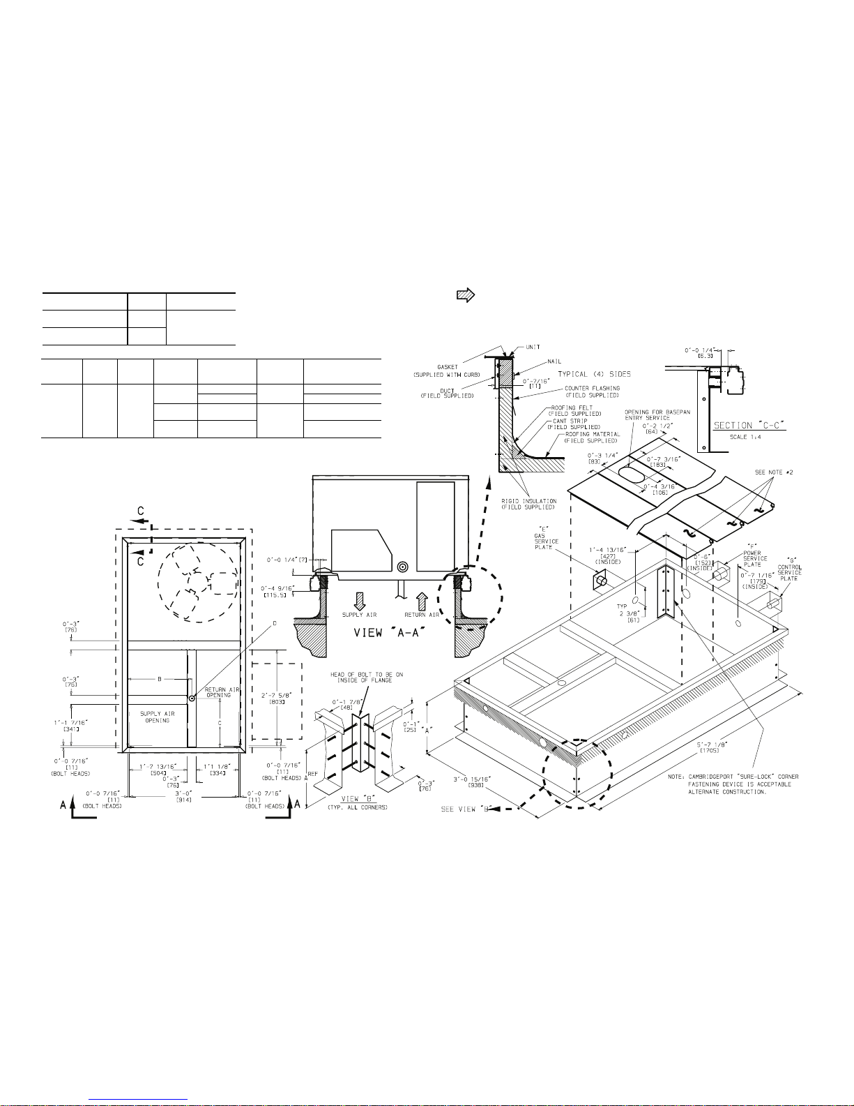
ROOF CURB — Assemb le and install accessor y roof cu rb in
accordance with instructions shipped with curb. See Fig. 2. Install insulation, cant strips, roofing felt, and counter flashing as
shown. Ductwork must be attached to curb, not to the unit. The
accessory thru-the-bottom power and gas connection package
must be installed before the unit is set on the roof curb. If field-
installed (thru-the-roof curb) gas connections are desired, use
factory-supplied
mount the thru-the-roof curb connection to the roof curb. Gas
connections and power connections to the unit must be field installed after the unit is installed on the roof curb.
If electric and control wiring is to be routed through the
basepan, attach the accessory thru-the-bottom service connections to the basepan in accordance with the accessory installation instructions.
3
/4-in. pipe coupling and gas plate assembly to
1
/2 psig, it must be
Manufacturer reserves the right to discontinue, or change at any time, specifications or designs without notice and without incurring obligations.
Book 1 4
Ta b 1 a 6 a
PC 111 Catalog No. 534-80000 Printed in U.S.A. Form 48TF-1SI Pg 1 8-00 Replaces: New
IMPORTANT: The gasketing of the unit to the roof curb
is critical for a watertight seal. Install gasket supplied
with the roof curb as shown in Fig. 2. Improperly
applied gasket can result in air leaks and poor unit
performance.
Page 2
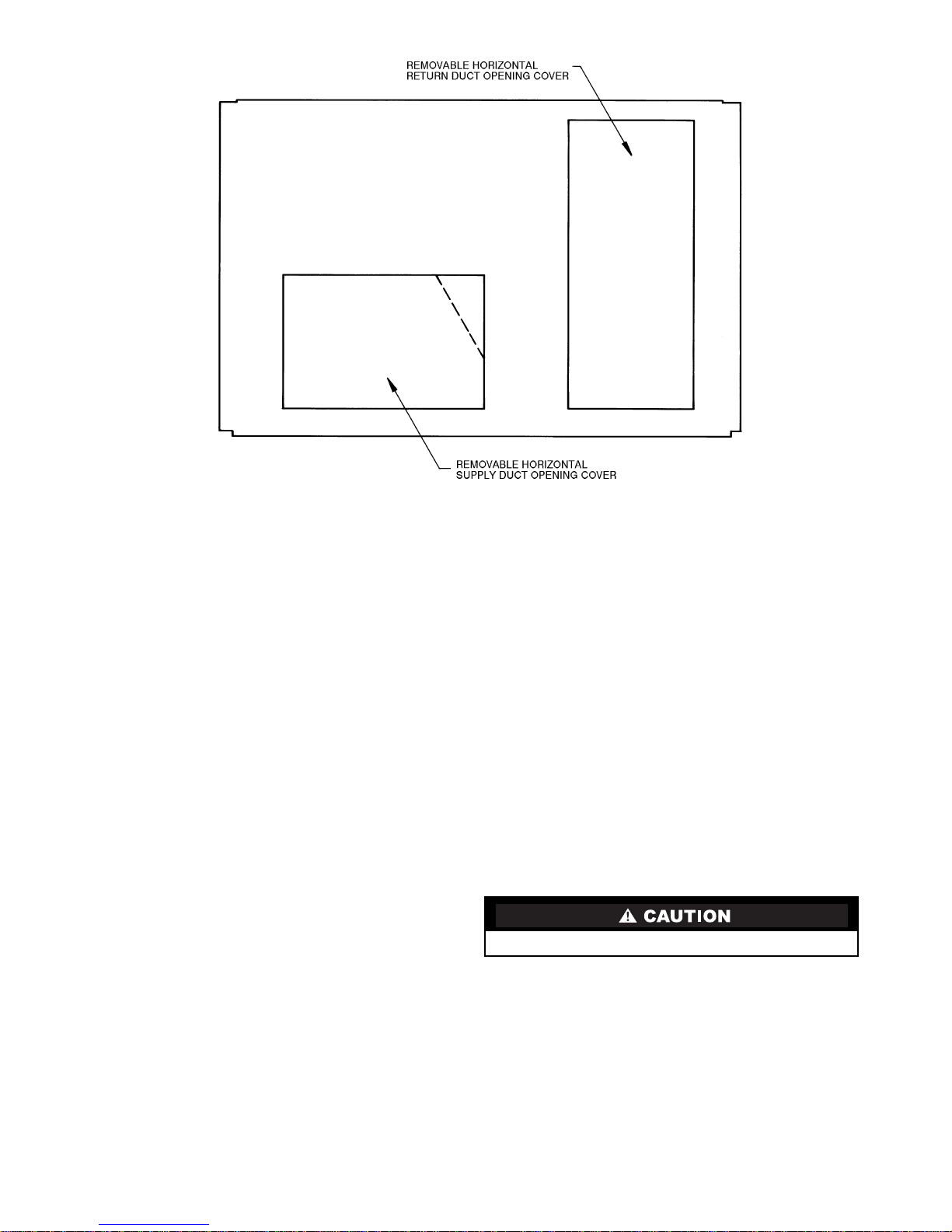
Fig. 1 — Horizontal Conversion Panels
Curb should be level. Unit leveling tolerances are shown in
Fig. 3. This is necessary for unit drain to function properly. Refer to Accessory Roof Curb Installation Instructions for additional information as required.
SLAB MOUNT (Horizontal Units Only) — Provide a level
concrete slab that extends a minimum of 6 in. beyond unit
cabinet. Install a gravel apron in front of condenser coil air inlet
to prevent grass and foliage from obstructing airflow .
NOTE: Horizontal units may be installed on a roof curb if
required.
Step 2 — Field Fabricate Ductwork —
Secure all
ducts to roof curb and building structure on vertical ducted
units. Do not connect ductwork to unit. For horizontal applica-
tions, field-supplied flanges should be attached to horizontal
duct openings and all ductwork should be secured to the
flanges. Insulate and weatherproof all external ductwork,
joints, and roof openings with counter flashing and mastic in
accordance with applicable codes.
Ducts passing through an unconditioned space must be in-
sulated and covered with a vapor barrier.
If a plenum return is used on a vertical unit, the return
should be ducted through the roof deck to comply with applicable fire codes.
A minimum clearance is not required around ductwork.
Cabinet return air static shall not exceed –.20 in. wg with
EconoMi$er, –.35 in. wg with Durablade economizer, or
–.45 in. wg without economizer.
These units are designed for a minimum continuous heating
return-air temperature of 50 F (dry bulb), or an intermittent operation down to 45 F (dry bulb), such as when used with a night
set-back thermostat.
Step 3 — Install External Trap for Condensate
Drain —
located on the bottom and side of the unit. Unit discharge connections do not determine the use of drain connections; either
drain connection can be used with vertical or horizontal
applications.
The unit’s 3/4-in. condensate drain connections are
When using the standard side drain connection, make sure
the plug (Red) in the alternate bottom connection is tight before
installing the unit.
To use the bottom drain connection for a roof curb installation, relocate the factory-installed plug (Red) from the bottom
connection to the side connection. See Fig. 4. The piping for
the condensate drain and external trap can be completed after
the unit is in place.
All units must have an external trap for condensate drainage. Install a trap at least 4-in. deep and protect agai nst freez eup. If drain line is installed downstream from the external trap,
pitch the line away from the unit at 1 in. per 10 ft of run. Do not
use a pipe size smaller than the unit connection (
Step 4 — Rig and Place Unit —
3
/4 in.).
Inspect unit for
transportation damage. File any claim with transportation
agency. Keep unit upright and do not drop. Spreader bars are
not required if top crating is left on unit. Rollers may be used to
move unit across a roof. Level by using unit frame as a reference. See Table 1 and Fig. 5 for additional information.
Lifting holes are provided in base rails as shown in Fig. 6.
Refer to rigging instructions on unit.
All panels must be in place when rigging.
POSI TION I NG — Maintain clearance around and above unit
to provide minimum distance from combustible materials,
proper airflow, and service access. See Fig. 6. A properly positioned unit will have the following clearances between unit and
roof curb:
1
/4-in. clearance between roof curb and base rails on
each side and duct end of unit; 1/4-in. clearance between roof
curb and condenser coil end of unit. (See Fig. 2, section C-C.)
Do not install unit in an indoor location. Do not locate unit
air inlets near exhaust vents or other sources of contaminated
air.
Be sure that unit is installed such that snow will not block
the combustion intake or flue outlet.
2
Page 3
3
Fig. 2 — Roof Curb Dimensions
ROOF CURB
ACCESSORY
A UNIT SIZE
CRRFCURB001A00
1′-2″
[356]
48TF004-007
CRRFCURB002A00
2′-0″
[610]
NOTES:
1. Roof curb accessory is shipped disassembled.
2. Insulated panels.
3. Dimensions in [ ] are in millimeters.
4. Roof curb, galvanized steel.
5. Attach ductwork to curb (flanges of duct rest on curb).
6. Service clearance: 4 ft on each side.
BC
D ALT
DRAIN
HOLE
“E”
GAS
“F”
POWER
“G”
CONTROL
CONNECTOR
PKG. ACCY.
1′-9
11
/16″
[551]
1′-4″
[406]
13/4″
[44.5]
3
/4″
[19] NPT
3
/4″ [19] NPT)
1
/2″
[12.7]
CRBTMPWR001A00
1
1
/4″ [31.7] CRBTMPWR002A00
1
/2″
[12.7] NPT
3
/4″ [19] NPT
1
/2″
[12.7]
CRBTMPWR003A00
3
/4″
[19] NPT
11/4″ [31.7] CRBTMPWR004A00
7. Direction of airflow.
8. Connector packages CRBTMPWR001 A00 and 002A0 0 are for thru-the curb connections. Packages CRBTMPWR003A00 and 004A 00 are for
thru-the-bottom connections.
Page 4
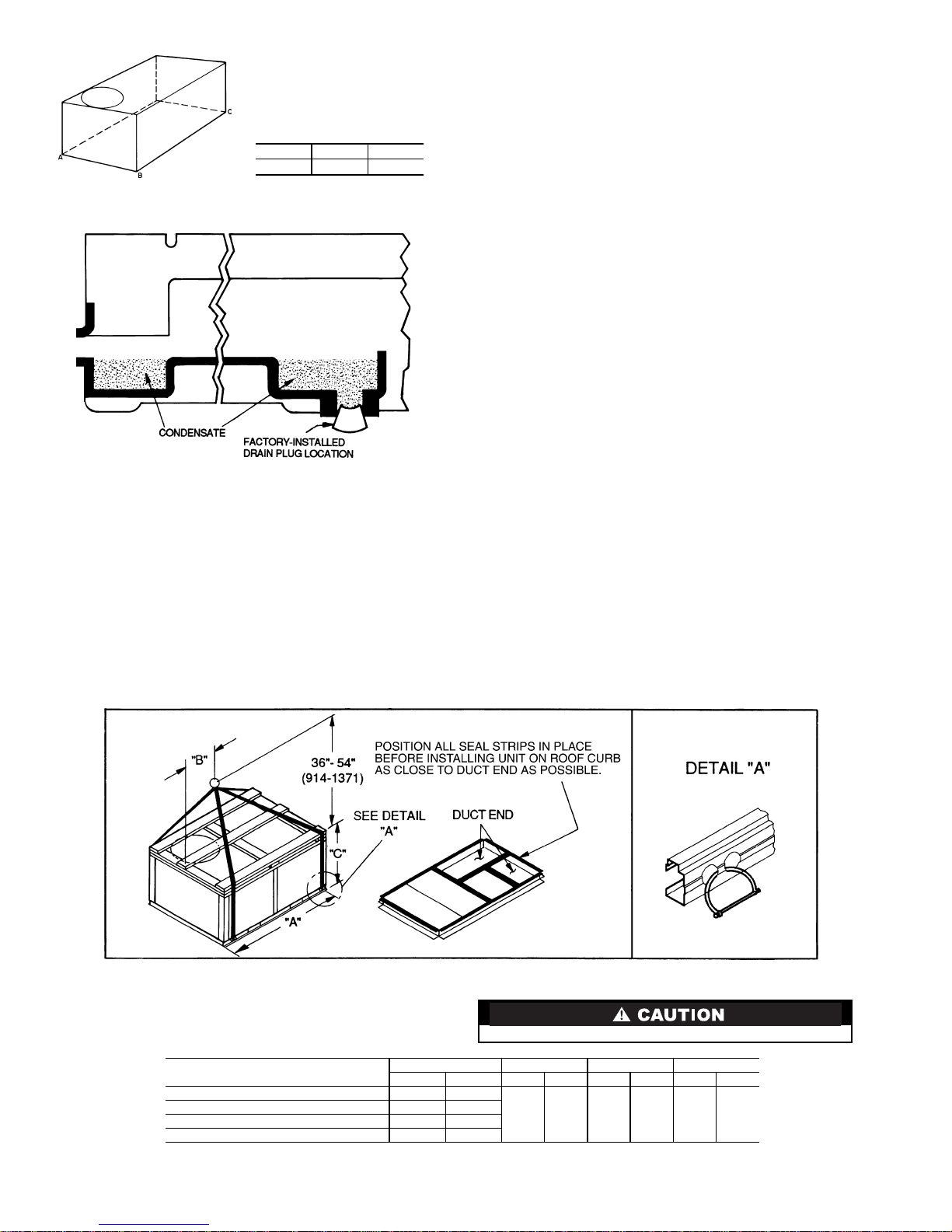
MAXIMUM ALLOWABLE
DIFFERENCE (in.)
A-B B-C A-C
0.5 1.0 1.0
Fig. 3 — Unit Leveling Tolerances
OTE: Drain plug is shown in factory-installed position.
Fig. 4 — Condensate Drain Connection
Unit may be installed directly on wood flooring or on
Class A, B, or C roof-covering material when roof curb is used.
Although unit is weatherproof, guard against water from
higher level runoff and overhangs.
Flue vent discharge must have a minimum horizontal clearance of 4 ft from electric and gas meters, gas regulators, and
gas relief equipment.
Minimum distance between unit and other electrically live
parts is 48 inches.
Flue gas can deteriorate building materials. Orient unit such
that flue gas will not affect building materials.
Adequate combustion-air space must be provided for proper
operation of this equipment. Be sure that installation complies
with all local codes and Section 5.3, Air for Combustion and
Ventilation, NFGC (National Fuel Gas Code), and ANSI
(American National Standards Institute) Z223.1, and NFPA
(National Fire Protection Association) 54 TIA-54-84-1.
In Canada, installation must be in accordance with the
CAN1-B149 installation codes for gas burning appliances.
After unit is in position, remove rigging skids and shipping
materials.
Step 5 — Install Flue Hood —
Flue hood is shipped
screwed to the basepan beside the burner compa rtment access
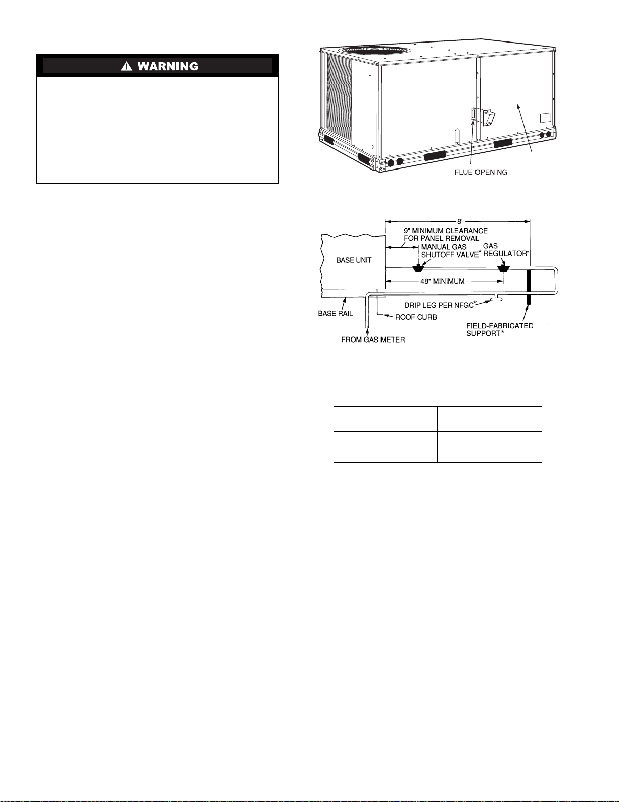
panel. Remove from shipping location and using screws provided, install flue hood and screen in location shown in Fig. 7.
Step 6 — Install Gas Piping —
Unit is equipped for
use with type of gas shown on nameplate. Refer to local building codes, or in the absence of local codes, to ANSI Z223.1 entitled National Fuel Gas Code. In Canada, installation must be
in accordance with the CAN1.B149.1 and CAN 1.B149.2 installation codes for gas burning appliances.
For natural gas applications, gas pressure at unit gas con-
nection must not be less than 4 in. wg or greater than
13.0 in. wg while unit is operating. On 48TF005,006,007 high
heat units, the gas pressure at unit gas connection must not be
less than 5 in. wg or greater than 13 in. wg while the unit is operating. For propane applications, the gas pressure must not
be less than 5 in. wg or greater than 13 in. wg at the unit
connection.
Size gas supply piping for 0.5 in. wg maximum pressure
drop. Do not use supply pipe smaller than unit gas connection.
Support gas piping as shown in the table in Fig. 8. For exam-
3
ple, a
/4-in. gas pipe must have one field-fabricated support
beam every 8 ft. Therefore, an 18-ft long gas pipe would have a
minimum of 2 support beams, a 48-ft long pipe would have a
minimum of 6 support beams.
See Fig. 8 for typical pipe guide and locations of external
manual main shutoff valve.
NOTES:
1. Dimensions in ( ) are in millimeters.
2. Hook rigging shackle s through holes in base rail, as shown in detail “A.’
Holes in base rails are centered around the unit center of gravity. Use
wooden top skid when rigging to prevent rigging straps from damaging unit.
UNIT
48TFE,TFF,TFM,TFN004 510 231
48TFD,TFE,TFF ,TFL,TFM,TFN005 520 236
48TFD,TFE,TFF ,TFL,TFM,TFN006 540 245
48TFD,TFE,TFF007 615 279
3. Unit weights do not include economizer. See Table 1 for economizer
weights.
All panels must be in place when rigging.
MAX WEIGHT “A” “B” “C”
Lb Kg in. mm in. mm in. mm
73.69 1872 37.50 953 33.35 845
Fig. 5 — Rigging Details
4
Page 5
Table 1 — Physical Data — 48TF004-007
UNIT SIZE 48TF E/F/M/N004 D/E/F/L/M/N005 D/E/F/L/M/N006 D/E/F007
NOMINAL CAPACITY (tons) 3456
OPERATING WEIGHT (lb)
Unit
Al/Al* 460 470 490 565
Al/Cu* 465 476 497 576
Cu/Cu* 468 482 505 587
Economizer
Durablade 34 34 34 34
EconoMi$er 47 47 47 47
Roof Curb† 115 115 115 115
COMPRESSOR Reciprocating
Quantity 1111
No. Cylinders (per Circuit) 2222
Oil (oz) 50 50 50 54
REFRIGERANT TYPE R-22
Expansion Device Acutrol™ Metering Device
Operating Charge (lb-oz)
Circuit 1 4-4 6-6 6-14 9-0
Circuit 2 ————
CONDENSER COIL Enhanced Copper Tubes, Aluminum Lanced Fins
Rows...Fins/in. 1...17 2...17 2...17 2...17
Total Face Area (sq ft) 8.36 8.36 10.42 10.42
CONDENSER FAN Propeller Type
Nominal Cfm 3500 4000 4000 4000
Quantity...Diameter (in.) 1...22.0 1...22.0 1...22.0 1...22.0
Motor Hp...Rpm
Watts Input (Total) 325 325 325 325
EVAPORATOR COIL Enhanced Copper Tubes, Aluminum Double-Wavy Fins
Rows...Fins/in. 2...15 2...15 3...15 4...15
Total Face Area (sq ft) 4.17 5.5 5.5 5.5
EVAPORATOR FAN Centrifugal Type
Quantity...Size (in.) Std 1...10 x 10 1...10 x 10 1...11 x 10 1...10 x 10
Type Drive Std Direct Direct Direct Belt
Nominal Cfm 1200 1600 2000 2400
Maximum Co ntinuous Bhp Std .34 .75 1.20 2.40
Motor Frame Size Std 48 48 48 56
Nominal Rpm High/Low Std 860/800 1075/970 1075/970 —
Fan Rpm Range Std — — — 1070-1460
Motor Bearing Type Ball Ball Ball Ball
Maximum Allowable Rpm 2100 2100 2100 2100
Motor Pulley Pitch Diameter Min/Max (in.) Std — — — 2.8/3.8
Nominal Motor Shaft Diameter (in.) Std
Fan Pulley Pitch Diameter (in.) Std ———4.5
Belt, Quantity...Type...Length (in.) Std — — — 1...A...40
Pulley Center Line Dis tance (in.) Std — — — 14.7-15.5
Speed Change per Full Turn of Std ———80
Movable Pulley Flange (rpm) Alt 48 70 80 —
Movable Pulley Maximum Full Turns Std ——— 5
From Closed Position Alt 555—
Factory Setting Std ——— 3
Factory Speed Setting (rpm) Std ———1225
Fan Shaft Diameter at Pulley (in.)
Alt 1...10 x 10 1...10 x 10 1...10 x 10 —
High-Static 1...10 x 10 1...10 x 10 1...11 x 10 1...10 x 10
Alt Belt Belt Belt —
High-Static Belt Belt Belt Belt
Alt 1.00 1.00 1.30/2.40** —
High-Static 2.40 2.40 2.90 2.90
Alt 48 48 56 —
High-Static 56 56 56 56
Alt 1620 1620 1725 —
High-Static 1725 1725 1725 1725
Alt 760-1000 835-1185 900-1300 —
High-Static 1075-1455 1075-1455 1300-168 5 1300-1685
Alt 1.9/2.9 1.9/2.9 2.4/3.4 —
High-Static 2.8/3.8 2.8/3.8 3.4/4.4 3.4/4.4
Alt
High-Static
Alt 4.5 4.0 4.5 —
High-Static 4.5 4.5 4.5 4.5
Alt 1...A...34 1...A...34 1...A...39 —
High-Static 1...A...39 1...A...39 1...A...40 1...A...40
Alt 10.0-12.4 10.0-12.4 14.7-15.5 —
High-Static 10.0-12.4 10.0-12.4 14.7-15.5 14.7-15.5
High-Static 65 65 60 60
High-Static 6655
Alt 333—
High-Static 3
Alt 856 975 1060 —
High-Static 1233 1233 1396 1396
LEGEND
Al — Aluminum
Bhp — Brake Horsepower
Cu — Copper
*Evaporator coil fin material/co ndenser coil fin material. Cont act your local
representative for details about coated fins.
†Weight of 14-in. roof curb.
**Single phase/three-phase.
1
/4...1100
1
/
1
/
5
/
1
5
/
1
/4...1100
1
31/
/
2
1
/
2
5
/
8
2
5
/
8
2
2
8
/
2
8
††Rollout switch lockout is manually reset by interrupting power to unit or
resetting thermostat.
|| Single- phase unit s have a single-st age gas valve. The heating in put values
are as follows:
48TFF004, 115,000 Btuh
48TFF005, 150,000 Btuh
48TFF006, 150,000 Btuh
1
/4...1100
1
/
5
/
5
/
31/
5
/
2
8
8
2
8
NOTE: High-static motor not available on single-phase units.
Scroll
1
/4...1100
5
/
—
5
/
31/
5
/
8
8
2
8
5
Page 6
Table 1 — Physical Data — 48TF004-007 (cont)
UNIT SIZE 48TF E/F/M/N004 D/E/F/L/M/N005 D/E/F/L/M/N006 D/E/F007
FURNACE SECTION
Rollout Switch Cutout
Temp (F)†† 195 195 195 195
Burner Orifice Diameter
(in. ...drill size)
Natural Gas Std TFD — .113...33 .113...33 .113...33
Liquid Propane Alt TFD — .089...43 .089...43 .089...43
Thermostat Heat Anticipator
Setting (amps)
208/230 v and 575 Stage 1 .14 .14 .14 .14
460 v Stage 1 .14 .14 .14 .14
Gas Input (B tuh)|| Stage 1 TFD — 72,000 72,000 72,000
Efficiency (Steady
State) (%) 80 80 80 80
Temperature Rise Range TFD — 25-55 25-55 25-55
Manifold Pressure (in. wg)
Natural Gas Std 3.5 3.5 3.5 3.5
Liquid Propane Alt 3.5 3.5 3.5 3.5
Gas Valve Quantity 1111
Gas Valve Pressure Range
Psig 0.180-0.487 0.180-0.487 0.180-0.487 0.180-0.487
in. wg 5.0-13.5 5.0-13.5 5.0-13.5 5.0-13.5
Field Gas Connection
Size (in.)
HIGH-PRESSURE SWITCH (psig)
Standard Com p ressor 450 ± 50 500 ± 50
Internal Relief (Differential)
Cutout 428 428
Reset (Auto.) 320 320
LOSS-OF-CHARGE (LOWPRESSURE SWITCH) (psig)
Cutout
Reset (Auto.) 22 ± 7
FREEZE PROTECTION
THERMOSTAT (F)
Opens 30 ± 5
Closes 45 ± 5
OUTDOOR-AIR INLET SCREENS Cleanable
Quantity...Size (in.) 1...20 x 24 x 1
RETURN-AIR FILTERS Throwaway
Quantity...Size (in.) 2...16 x 25 x 2
Stage 2 .14 .14 .14 .14
Stage 2 .14 .14 .14 .14
Stage 2
(3-phase units)
LEGEND
Al — Aluminum
Bhp — Brake Horsepower
Cu — Copper
*Evaporator coil fin material/co ndenser coil fin material. Cont act your local
representative for details about coated fins.
†Weight of 14-in. roof curb.
**Single phase/three-phase.
TFE .113...33 .113...33 .113...33 .113...33
TFF .113...33 .129...30 .129...30 .129...30
TFL — .102...38 .102...38 —
TFM .102...38 .102...38 .102...38 —
TFN .102...38 .116...32 .116...32 —
TFE .089...43 .089...43 .089...43 .089...43
TFF .089...43 .102...38 .102...38 .102...38
TFL — .082...45 .082...45 —
TFM .082...45 .082...45 .082...45 —
TFN .082...45 .089...43 .089...43 —
TFE 72,000 115 ,00 0 115,000 115 ,00 0
TFF 82,000 120,000 120,00 0 120,000
TFL — 60,000 60,000 —
TFM 60,000 90,000 90,000 —
TFN 90,000 120,000 120,000 —
TFF 115,000 150,000 150,000 150,000
TFE 25-55 35-65 35-65 35-65
TFF 55-85 50-80 50-80 50-80
TFL — 20-50 20-50 —
TFM 20-50 30-60 30-60 —
TFN 30-60 40-70 40-70 —
1
/
2
1
/
2
1
/
2
1
/
2
7 ± 3
††Rollout switch lockout is manually reset by interrupting power to unit or
resetting thermostat.
|| Single-phase units have a single-stage gas valve. The heating input values
are as follows:
48TFF004, 115,000 Btuh
48TFF005, 150,000 Btuh
48TFF006, 150,000 Btuh
NOTE: High-static motor not available on single-phase units.
6
Page 7
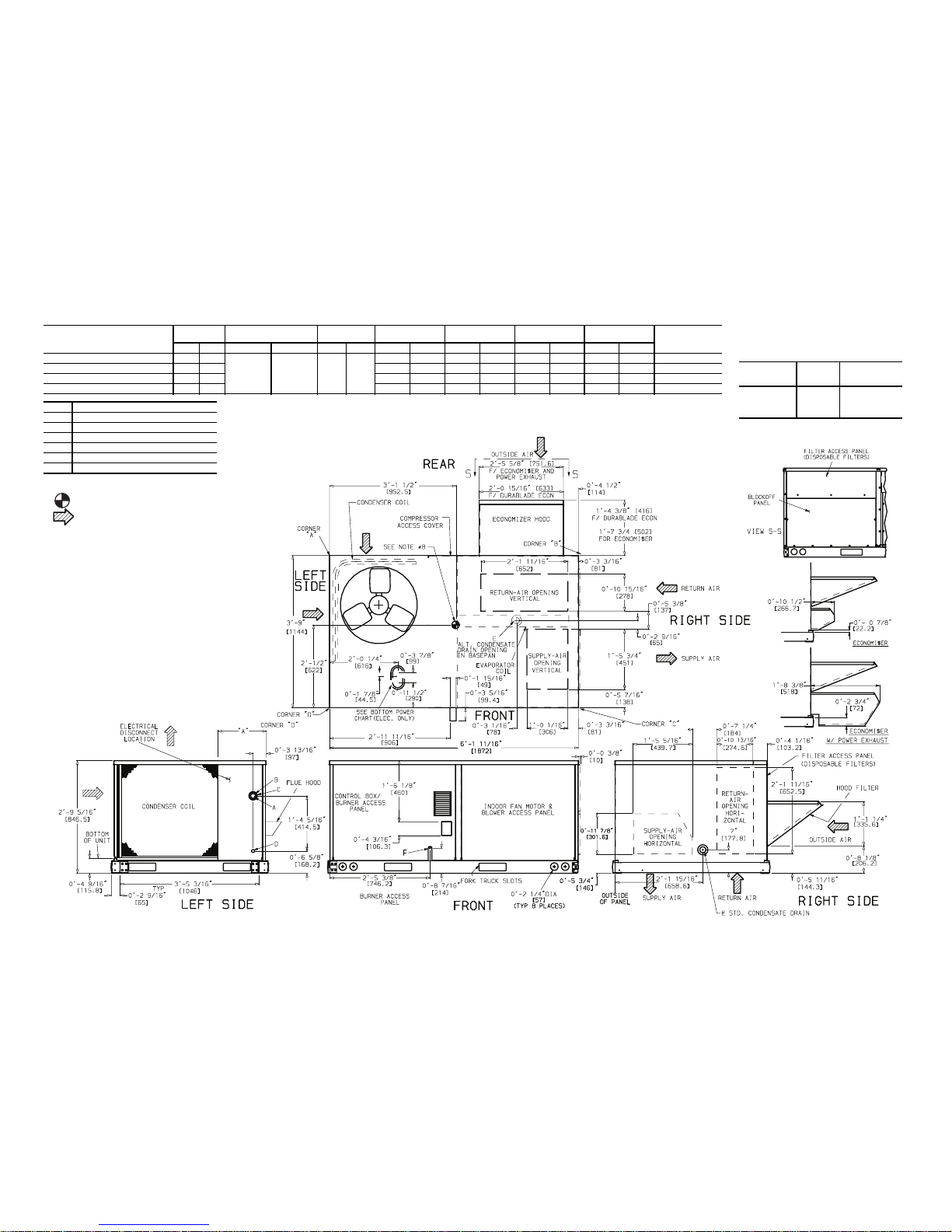
7
Fig. 6 — Base Unit Dimensions
UNIT
STD UNIT
WEIGHT
DURABLADE
ECONOMIZER WEIGHT
ECONOMI$ER
WEIGHT
(A)
CORNER WEIGHT
(B)
CORNER WEIGHT
(C)
CORNER WEIGHT
(D)
CORNER WEIGHT
“A”
PANEL
LENGTH
Lbs Kg Lbs Kg Lbs Kg Lbs Kg Lbs Kg Lbs Kg Lbs Kg
48TFN,TFM,TFF,TFE004
460 209
34 15.4 47 21.3
140 63.5 105 47.6 159 72.1 56 25.4 1′-10
3
/
8
″
[568.0]
48TFN,TFM,TFL,TFF,TFE,TFD005
470 213 142 64.4 106 48.1 162 73.5 60 27.2 1′-10
3
/
8
″
[568.0]
48TFN,TFM,TFL,TFF,TFE,TFD006
490 222 150 68.0 115 52.2 160 72.6 65 29.5 1′-0
3
/
8
″
[315.0]
48TFF,TFE,TFD007
565 256 165 74.8 136 61.7 200 90.7 64 29.0 1′-0
3
/
8
″
[315.0]
BOTTOM POWER CHART,
THESE HOLES REQ’D FOR USE
WITH ACCESSORY PACKAGES —
CRBTMPWR001A00, 3A00 (
1
/2″, 3/4″)
THREADED
CONDUIT
SIZE
WIRE
USE
REQ’D HOLE
SIZES
(Max.)
1
/
2
″
24 V
7
/
8
″
[22.2]
3
/
4
″
Power 1
1
/
8
″
[28.4]
1
/
2
″
FPT
Gas 1
1
/
4
″
[31.8]
CONNECTION SIZES
A
1
3
/
8
″
Dia. [35] Field Power Supply Hole
B
2″ Dia. [51] Power Supply Knockout
C
2
1
/
2
″
Dia. [64] Power Supply Knockout
D
7
/
8
″
Dia. [22] Field Control Wiring Hole
E
3
/
4
″
-14 NPT Condensate Drain
F
1
/
2
″
-14 NPT Gas Connection
NOTES:
1. Dimensions in [ ] are in millimeters.
2. Center of Gravity.
3. Direction of Airflow.
4. On vertical discharge units, ductwork to be attached to accessory
roof curb only. For horizontal discharge units, field-supplied flanges
should be attached to horizontal discharge openings, and all ductwork should be attached to the flanges.
5. Minimum clearance (local codes or jurisdiction may prevail):
a. Between unit, flue side and combustible surfaces, 36 inches.
b. Bottom of unit to combustible surfaces (when not using curb)
1 inch. Bottom of base rail to combustible surfaces (when not
using curb) 0 inches.
c. Condenser coil for proper airflow, 36 in. one side, 12 in. the other.
The side getting the greater clearance is optional.
d. Overhead, 60 in. to assure proper condenser fan operation.
e. Between units, control box side, 42 in. per NEC (National Electri-
cal Code).
f. Between unit and ungrounded surfaces, control box side, 36 in.
per NEC.
g. Between unit and block or concrete walls and other grounded sur-
faces, control box side, 42 in. per NEC.
h. Horizontal supply and return end, 0 inches.
6. With the exception of the clearance for the condenser coil and combustion side as stated in Note 5a, b, and c, a removable fence or barricade requires no clearance.
7. Units may be installed on combustible floors made from wood or
Class A, B, or C roof covering material if set on base rail.
8. The vertical center of gravity is 1′-6″ [457] up from the bottom of the
base rail.
Page 8
Step 7 — Make Electrical Connections
BLOWER
ACCESS
PANEL
LEGEND
NFGC —
National Fuel Gas Code
*Field supplied.
NOTE: Follow all local codes.
SPACING OF SUPPORTS
Fig. 8 — Gas Piping Guide (With Accessory
Thru-the-Curb Service Connections)
STEEL PIPE
NOMINAL DIAMETER
(in.)
X
DIMENSIONS
(feet)
1
/
2
6
3
/4 or 1
8
11/4 or larger
10
Fig. 7 — Flue Hood Details
Unit cabinet must have an uninterrupted, unbroken electrical ground to minimize the possibility of personal injury if
an electrical fault should occur. This ground may consist of
electrical wire connected to unit ground lug in control compartment, or conduit approved for electrical ground when
installed in accordance with NEC (National Electrical
Code), ANSI/NFPA, latest edition, and local electrical
codes. Do not use gas piping as an electrical ground. Fail-
ure to follow this warning could result in the installer being
liable for personal injury of others.
FIELD POWER SUPPLY — All units except 208/230-v
units are factory wired for the voltage shown on the nameplate.
If the 208/230-v unit is to be connected to a 208-v power supply, the transformer must be rewired by moving the black wire
with the
nection and moving to the 200-volt
primary side of the transformer.
tails are provided for field wire connections. Use factorysupplied splices or UL (Underwriters’ Laboratories) approved
copper/aluminum connector .
requirements.
Install field wiring as follows:
within voltage range indicated on unit nameplate (see Table 2).
On 3-phase units, voltages between phases must be balanced
within 2% and the current within 10%. Use the formula shown
in the legend for Table 2, Note 2 to determine the percent of
voltage imbalance. Operation on improper line voltage or excessive phase imbalance constitutes abuse and may cause damage to electrical components. Such operation would invalidate
any applicable Carrier warranty.
FIELD CO NTROL WIRING — Install a Carrier-approved
accessory thermostat assembly according to installation
instructions included with the acc essory. Locate thermostat assembly on a solid wall in the conditioned space to sense ave rage temperature in accordanc e with thermostat ins tallation instructions. Connect thermostat wires to terminal board.
wire from subbase terminals through connector on unit to lowvoltage connections (shown in Fig. 10).
NOTE: For wire runs up 50 ft, use no. 18 AWG (American
Wire Gage) insulated wire (35 C minimum). For 50 to 75 ft,
use no. 16 AWG insulated wire (35 C minimum). For over
75 ft, use no. 14 AWG insulated wire (35 C minimum). All
wire larger than no. 18 AWG cannot be directly connected to
1
/4-in. female space connector from the 230-volt con-
1
/4-in. male terminal on the
Refer to unit label diagram for additional information. Pig-
When installing units, provide a disconnect per the NEC.
All field wiring must comply with NEC and local
1. Install conduit through side panel openings. For units
without electric heat, install conduit between disconnect
and control box.
2. Install power lines to terminal connections as shown in
Fig. 9.
Voltage to compressor terminals during operation must be
Route thermostat cable or equivalent single leads of colored
the thermostat and will require a junction box and splice at the
thermostat.
Pass the control wires through the hole provided in the corner post; then feed wires through the raceway built into the
corner post to the 24-v barrier located on the left side of the
control box. See Fig. 11. The raceway provides the UL required clearance between high- and low-voltage wiring.
HEAT ANTICIPATOR SETTINGS — Set heat anticipator
settings at .14 amp for the first stage and .14 amp for secondstage heating, when available.
8
Page 9
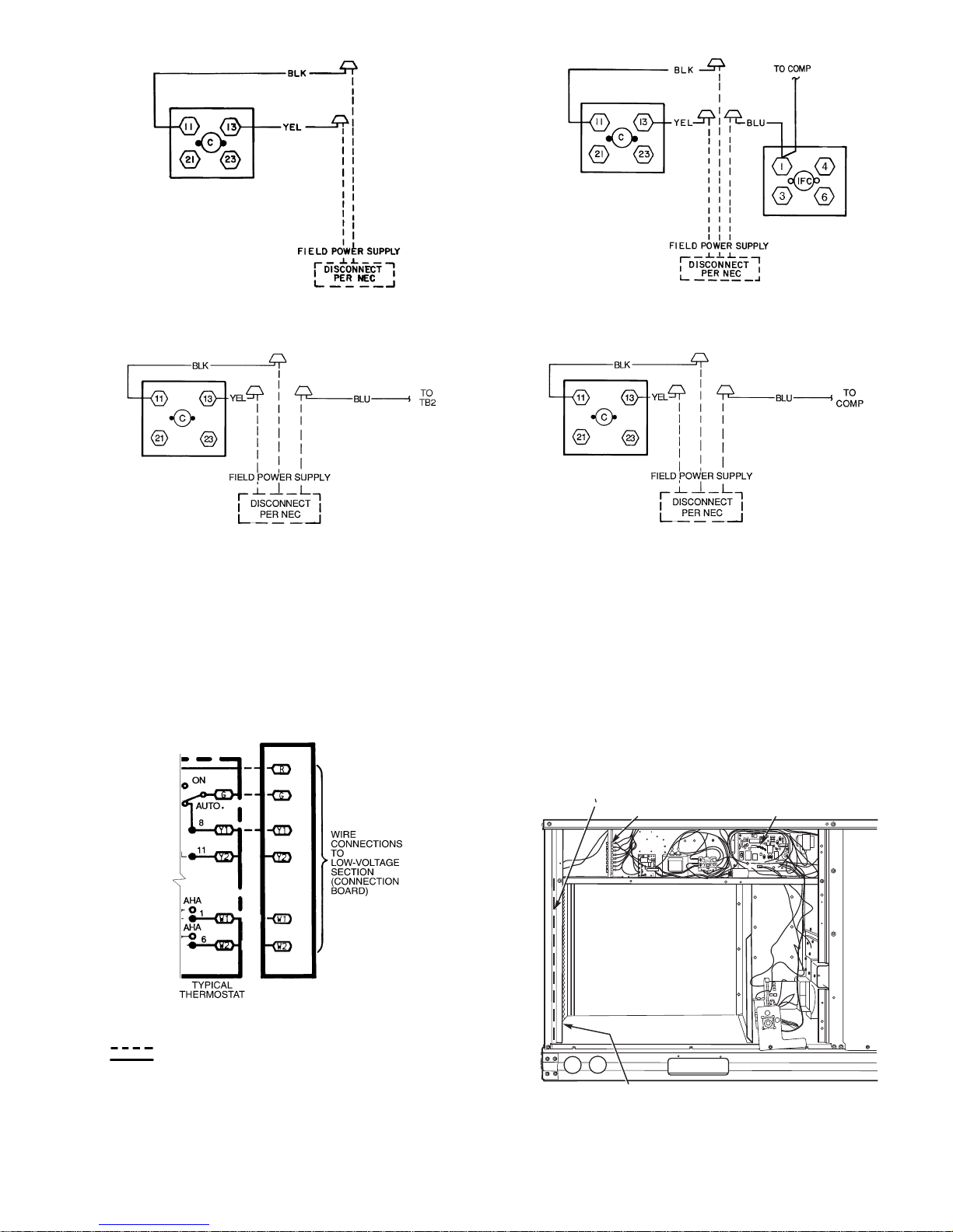
RACEWAY LOW VOLTAGE
CONNECTIONS
INTEGRATED GAS UNIT
CONTROLLER (IGC)
HOLE IN END PANEL (HIDDEN)
208/230-1-60
208/230-3-60
460-3-60
(SIZE 007 ONLY)
LEGEND
C—
COMP —
NEC —
TB —
575-3-60
(SIZE 007 ONLY)
Contactor
Compressor
National Electrical Code
Terminal Block
208/230-3-60
575-3-60, 460-3-60
(SIZES 004-006)
Fig. 9 — Power Wiring Connections
LEGEND
AHA —
NOTES:
1. Connect Y2 when unit is equipped with an economizer.
2. Connect W2 when unit is equipped with two stages of heat.
Adjustable Heat Anticipator
Field Wiring
Factory Wiring
Fig. 10 — Low-Voltage Connections
Fig. 11 — Field Control Wiring Raceway
9
Page 10
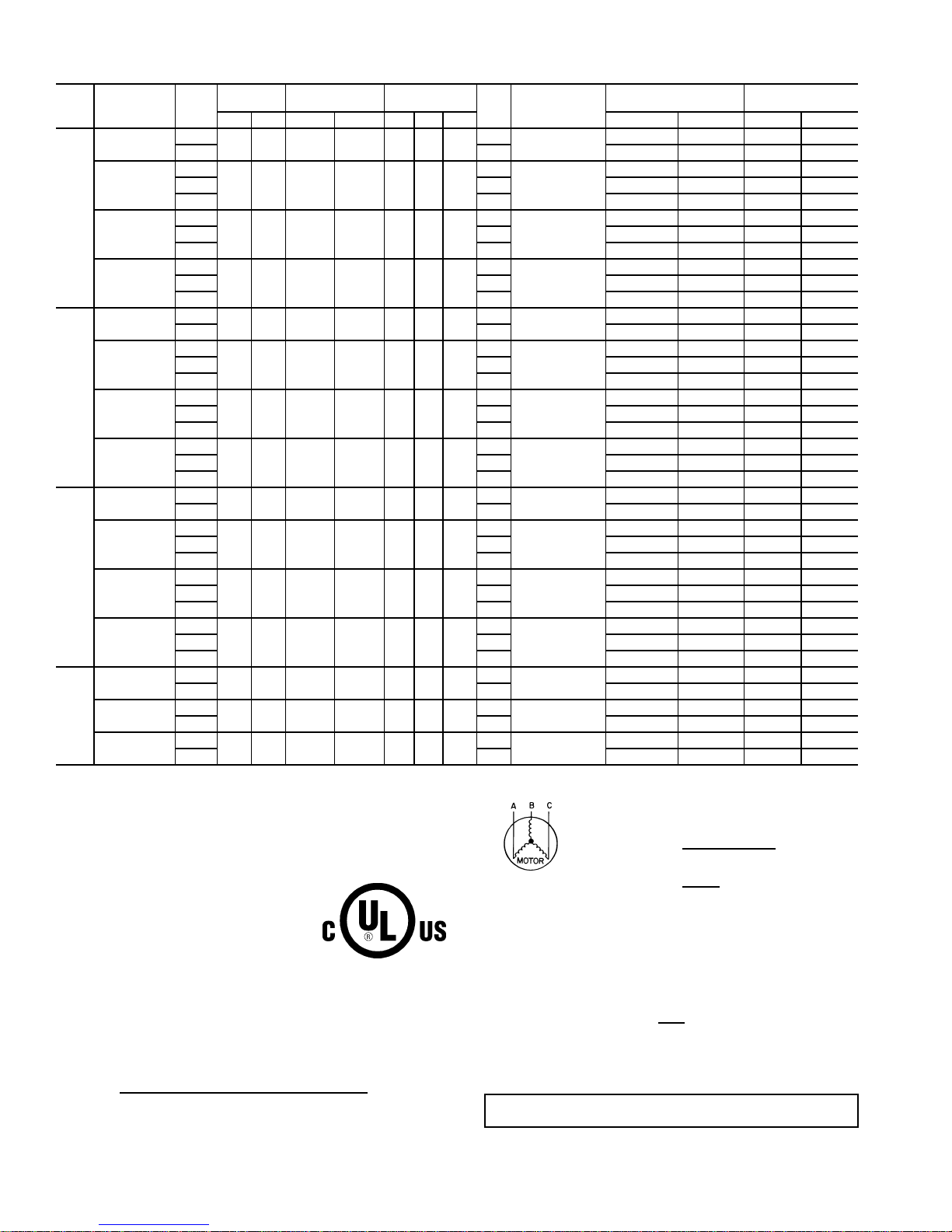
Table 2 — Electrical Data
UNIT
48TF
NOMINAL
V-Ph-Hz
208/230-1-60
VOLTAGE
IFM
TYPE
RANGE
Min Max RLA LRA Qty Hp FLA MCA MOCP† FLA LRA
Std
187 254 16.2 96.0 1
Alt 4.9 26.6/26.6 35/35 26/26 111/111
COMPRESSOR
(ea)
Std
208/230-3-60
187 254 10.2 75.0 1
Alt 4.9 19.1/19.1 25/25 19/19 90/90
High 5.2 19.4/19.4 25/25 19/19 109/109
004
460-3-60
Std
Alt 2.1 8.4 15 8 48/48
414 508 4.4 40.0 1
High 2.6 8.9 15 9 57/57
Std
575-3-60
Alt 2.1 6.9 15 8 37
518 632 3.7 31.0 1
High 2.6 7.3 15 7 45
208/230-1-60
Std
187 254 23.3 118.0 1
Alt 4.9 35.4/35.4 45/45 34/34 133/133
Std
208/230-3-60
187 254 15.4 90.0 1
Alt 4.9 25.6/25.6 30/30 25/25 105/105
High 5.2 25.9/25.9 30/30 25/25 124/124
005
460-3-60
Std
Alt 2.1 13.3 20 13 53
414 508 8.3 45.0 1
High 2.6 13.8 20 13 62
Std
575-3-60
Alt 2.1 10.3 15 11 42
518 632 6.4 36.0 1
High 2.6 10.7 15 10 50
208/230-1-60
Std
187 254 28.8 147 1
Alt 6.6 44.0/44.0 60/60 42/42 184/184
Std
208/230-3-60
187 254 16.3 114 1
Alt 5.2 26.6/26.6 35/35 26/26 148/148
High 7.5 28.9/28.9 35/35 29/29 174/174
006
460-3-60
Std
Alt 2.6 12.7 15 12 81
414 508 7.4 64 1
High 3.4 13.5 20 13 94
Std
575-3-60
Alt 3.0 10.5 15 10 66
518 632 6.2 62 1
High 3.4 12.6 15 11 76
Std
187 254 23.6 146 1
High 7.5 32.5/32.5 40/40 32/32 205/205
Std
414 508 10.6 73 1
High 3.4 16.1 20 16 103
Std
518 632 8.5 58.4 1
High 3.4 12.9 20 14 82
007
208/230-3-60
460-3-60
575-3-60
LEGEND
FLA — Full Load Amps
HACR — Heating, Air Conditioning and Refrigeration
IFM — Indoor (Evaporator) Fan Motor
LRA — Locked Rotor Amps
MCA — Minimum Circuit Amps
MOCP — Maximum Overcurrent Protection
NEC — National Electrical Code
OFM — Outdoor (Condenser) Fan Motor
RLA — Rated Load Amps
*Used to determine minimum disconnect per NEC.
†Fuse or HACR circuit breaker.
NOTES:
1. In compliance with NEC requirements for multimotor and combination
load equipment (refer to NEC Articles 430 and 440), the overcurrent
protective device for th e uni t sha ll be f use o r HA CR br eak er. Canadian
units may be fuse or circuit breaker.
2.
Unbalanced 3-Phase Supply Voltage
Never operate a motor where a phase imbalance in supply voltage is
greater than 2%.
of voltage imbalance.
Use the following formula to determine the percent
% Voltage Imbalance
= 100 x
max voltage dev i ation from average voltage
average voltage
OFM
(ea)
1
/41.4
1
/41.4
1
/40.8
1
/40.8
1
/41.4
1
/41.4
1
/40.8
1
/40.8
1
/41.4
1
/41.4
1
/40.8
1
/40.8
1
/41.4
1
/40.6
1
/40.6
IFM
FLA
3.5
3.5
COMBUSTION
FAN MOTOR
FLA
.6
POWER
SUPPLY
24.5/24.5 30/30 23/23 106/106
17.7/17.7 25/25 17/17 85/85
DISCONNECT
SIZE*
.6
1.3
7.6 15 7 48/48
.3
1.3
6.3 15 7 35
.3
3.5
3.5
.6
34.0/34.0 40/40 32/32 129/129
24.2/24.2 30/30 23/23 101/101
.6
1.8
13.0 20 13 51
.3
1.8
10.1 15 10 41
.3
5.9
5.9
.6
43.3/43.3 60/60 42/42 161/161
27.3/27.3 35/35 29/29 128/128
.6
3.1
13.2 20 13 72
.3
3.1
10.9 15 11 58
.3
5.2
2.6
2.6
.6
.3
.3
30.2/30.2 35/35 29/29 180/180
15.4 20 15 90
12.3 15 13 72
Example: Supply voltage is 460-3-60.
AB = 452 v
BC = 464 v
AC = 455 v
Average Voltage =
Determi ne maximum deviation from average volt ag e.
(AB) 457 – 452 = 5 v
(BC) 464 – 457 = 7 v
(AC) 457 – 455 = 2 v
452 + 464 + 455
1371
=
3
= 457
3
Maximum deviation is 7 v.
Determine percent of voltage imbalance.
% Voltage Imbalance = 100 x
7
457
= 1.53%
This amount of phase imbalance is satis f act ory as it is below t he maximum allowable 2%.
IMPORTANT:
than 2%, contact your loca l electric utility company immediately.
If the supply voltage phase imbalance is more
10
Page 11
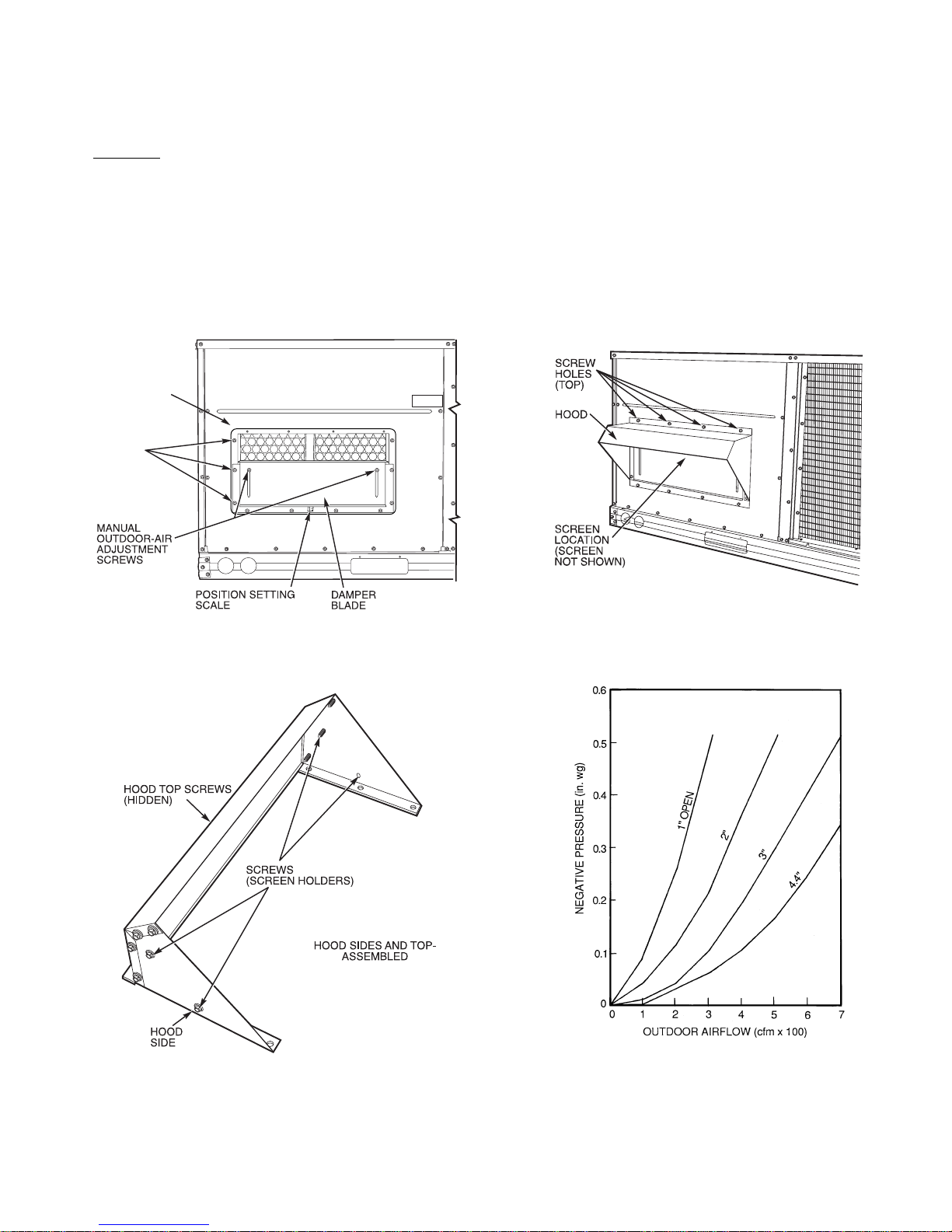
Step 8 — Make Outdoor-Air Adjustments and
Fig. 14 — Outdoor-Air Damper with
Hood Att ached
Fig. 15 — Position Setting
Install Outdoor-Air Hood
MANUAL OUTDOOR-AIR DAMPER — The outdoor-air
hood and screen are attached to the basepan at the bottom of
the unit for shipping.
Assembly:
1. Determine quantity of ventilation required for building.
Record amount for use in Step 8.
2. Remove and save outdoor air opening panel and screws.
See Fig. 12.
3. Separate hood and screen from basepan by removing the
4 screws securing them. Save all screws.
4. Replace evaporator coil access panel.
OUTDOOR
AIR OPENING
PANEL
3 SCREWS
(SIDE)
5. Place hood on front of outdoor air opening panel. See
Fig. 13 for hood details. Secure top of hood with the
4 screws removed in Step 3. See Fig. 14.
6. Remove and save 6 screws (3 on each side) from sides of
the manual outdoor-air damper.
7. Align screw holes on hood with screw holes on side of
manual outdoor-air damper. See Fig. 13 and 14. Secure
hood with 6 screws from Step 6.
8. Adjust minimum position setting of the damper blade by
adjusting the manual outdoor-air adjustment screws on
the front of the damper blade. See Fig. 12. Slide blade
vertically until it is in the appropriate position determined
by Fig. 15. Tighten screws.
9. Remove and save screws currently on sides of hood. Insert screen. Secure screen to hood using the screws. See
Fig. 14.
Fig. 12 — Damper Panel with Manual Outdoor-Air
Damper Installed
Fig. 13 — Outdoor-Air Hood Details
11
Page 12
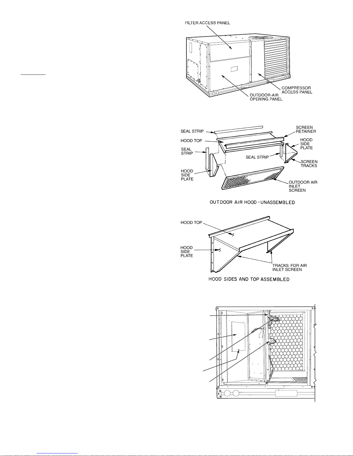
OPTIONAL DURABLADE ECONOMIZER — The op-
Fig. 16 — Typical Access Panel Locations
Fig. 17 — Outdoor-Air Hood Details
Fig. 18 — Horizontal Durablade Economizer
Installation
tional economizer hood assembly is packaged and shipped in
the filter section. Damper blades and control boards are installed at the factory and the economizer is shipped in the vertical discharge position.
NOTE: Horizontal discharge block-off plate is shipped with
the air hood package. If unit is to be used for vertical discharge
application, discard this plate.
Assembly:
1. Determine if ventilation air is required in building. If so,
determine minimum amount to be supplied by each unit
and record quantity of ventilation air needed for use in
Step 6.
2. Remove filter access panel by rais ing panel and s winging
panel outward. Panel is now disengaged from track and
can be removed. No tools are required to remove filter
access panel. Remove outdoor-air opening panel. Save
panels and screws. See Fig. 16. Remove optional
outdoor-air damper hood package from filter section.
3. Assemble outdoor-air hood top and side plates as shown
in Fig. 17. Install seal strips on hood top and sides. Put
aside screen retainer and screws for later assembly. Do
not attach hood to unit at this time.
4. To convert to horizontal discharge application:
a. Rotate economizer 90 degrees until the
economizer motor faces the condenser section
(see Fig. 18).
b. Rotate the barometric relief damper hinge
90 degrees. Barometric relief damper should open
vertically to operate properly.
c. Install horizontal discharge block-off plate over
the opening on the access panel. (Block-off plate
MUST be installed before installing hood assembly.) See Fig. 19.
5. Insert economizer plug into economizer harness. Remove
tape from barometric relief damper. See Fig. 20.
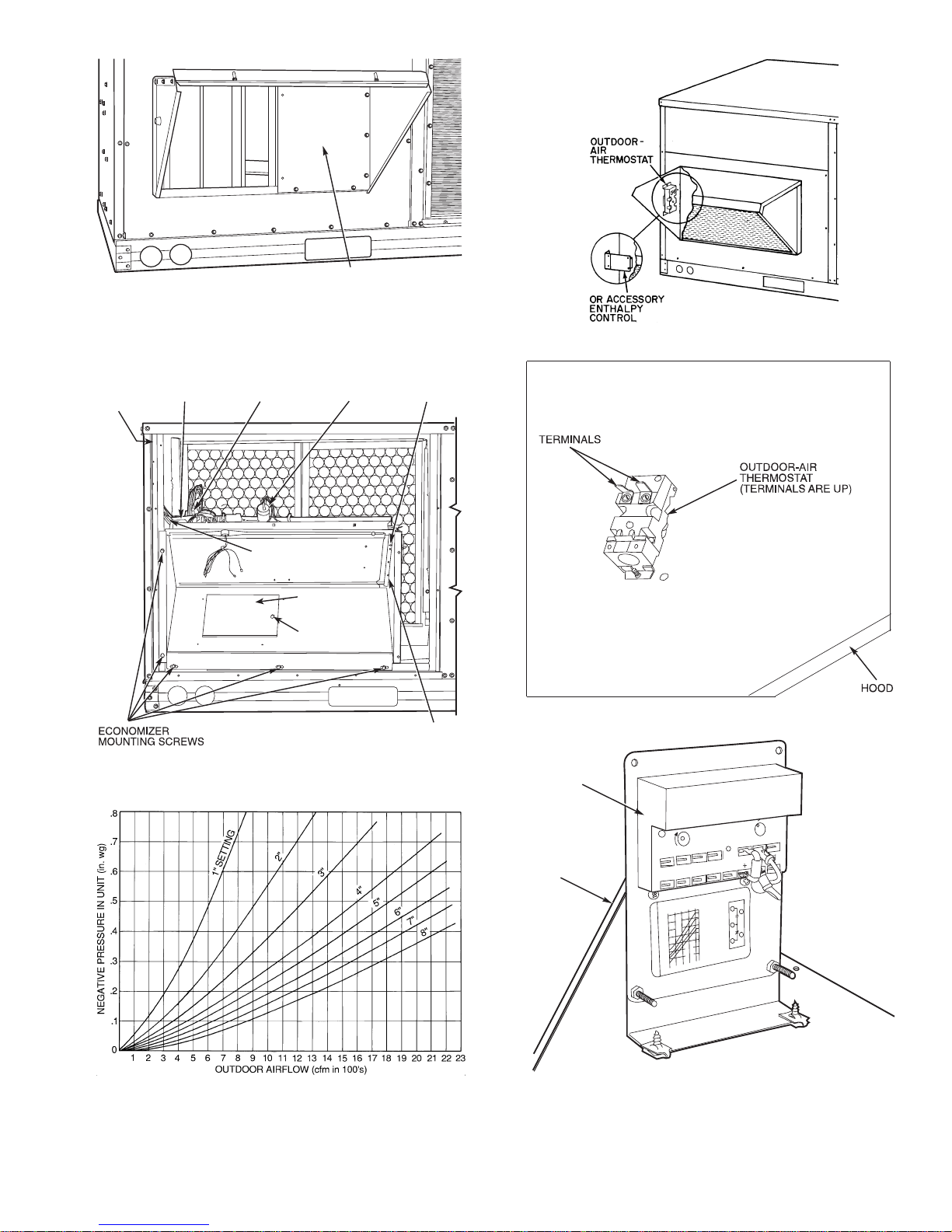
6. If ventilation air is not required, proceed t o Step 7. If ventilation air is required, determine minimum position setting for required airflow. See Fig. 21. Adjust minimum
position setting by adjusting the screws on the position
setting bracket. Slide bracket until the top screw is in the
position determined by Fig. 21. Tighten screws.
7. Remove tape from outdoor-air thermostat (OAT). Fasten
OAT to inside of hood using screws and speed c lips provided. See Fig. 22. Make sure OAT terminals are positioned up.
8. Replace outdoor-air opening panel using screws from
Step 2. Replace filter a ccess panel. Ensure the filter ac cess panel slides along the tracks and is securely engaged.
9. Fasten hood top and side plate assembly (Fig. 17) to
outdoor-air opening panel with screws provided.
10. Place knob supplied with economizer on OAT. See
Fig. 22. Set for 3° F below indoor room thermostat setting. If accessory enthalpy control (EC) is used in place of
OAT, see instructions shipped with EC for installation
and adjustment. See Fig. 22.
11. Connect OAT per Fig. 23.
12. Slide outdoor-air inlet screen into screen track on hood
side plate. While holding screen in place, fasten screen retainer to hood using screws provided.
NOTE: Refer to Fig. 24 for economizer barometric relief
damper characteristics.
ECONOMIZER
CONTROL
BOARD
BAROMETRIC
RELIEF
DAMPER
ECONOMIZER
PLUG
SHIPPING
SCREW
ECONOMIZER
MOTOR
12
Page 13
BLOCK-OFF PLATE
MINIMUM
POSITION
OPEN
3
1
T
P
P1
T1
4
2
5
S
S
O
D
C
TR
B
REV.B
198818A
%
H
U
M
I
D
I
T
Y
90
70
60
30
10
D
C
B
A
60
65
70
75
55
50
85
80
DAMPER
DAMPER
CLOSED
OPEN
OUTDOOR TEMP
.
°
F
REV
.
97-3672
CW–SETPOINTS–CCW
CONT
A
CTS SHO
WN IN HIGH ENTHALPY
RUSH
AT 24V
AC
3 mA
MIN. A
T 1
1 VDC
CONT
ACT RA
TINGS: 1.5A
RUN, 3.5A IN
OR UNPOWERED ST
A
TE
1
2
3
TR
TR1
24V
AC
ENTHALPY CONTROL
ENTHALPY
CONTROL
HOOD
Fig. 22 — Outdoor-Air Thermostat/
Enthalpy Control Installation
Fig. 19 — Horizontal Discharge Block-Off Plate
U-SHAPED
HOLE
(NOT
SHOWN)
ECONOMIZER
CONTROL
BOARD
ECONOMIZER
PLUG
WIRING
HARNESS
BAROMETRIC
RELIEF DAMPER
SHIPPING
SCREW
ECONOMIZER
MOTOR
POSITION SETTING
BRACKET
TOP
SCREW
Fig. 20 — Durablade Economizer Installed in Unit
EXAMPLE:
Given —Negative Pressure. . . . . . . . . . . . . . . . . . . . . . . 0.2 in. wg
Determine — Setting = 5 in.
Outdoor Air . . . . . . . . . . . . . . . . . . . . . . . . . . . . . 900 cfm
Fig. 21 — Durablade Economizer
Minimum Position Setting
13
Page 14
OUTDOOR AIR
OPENING PANEL
SEAL STRIP
EXHAUST AIR SCREEN
EXHAUST AIR
HOOD TOP
SCREEN
RETAINER
EXHAUST AIR
HOOD SIDES
EXHAUST AIR
BOTTOM BRACKET
Fig. 26 — Typical Access Panel Locations
Fig. 27 — Exhaust Air Hood Assembly
LEGEND
Outdoor-Air Thermostat
OAT —
NOTE: See unit wiring diagram for details.
Fig. 23 — Wiring Connections for
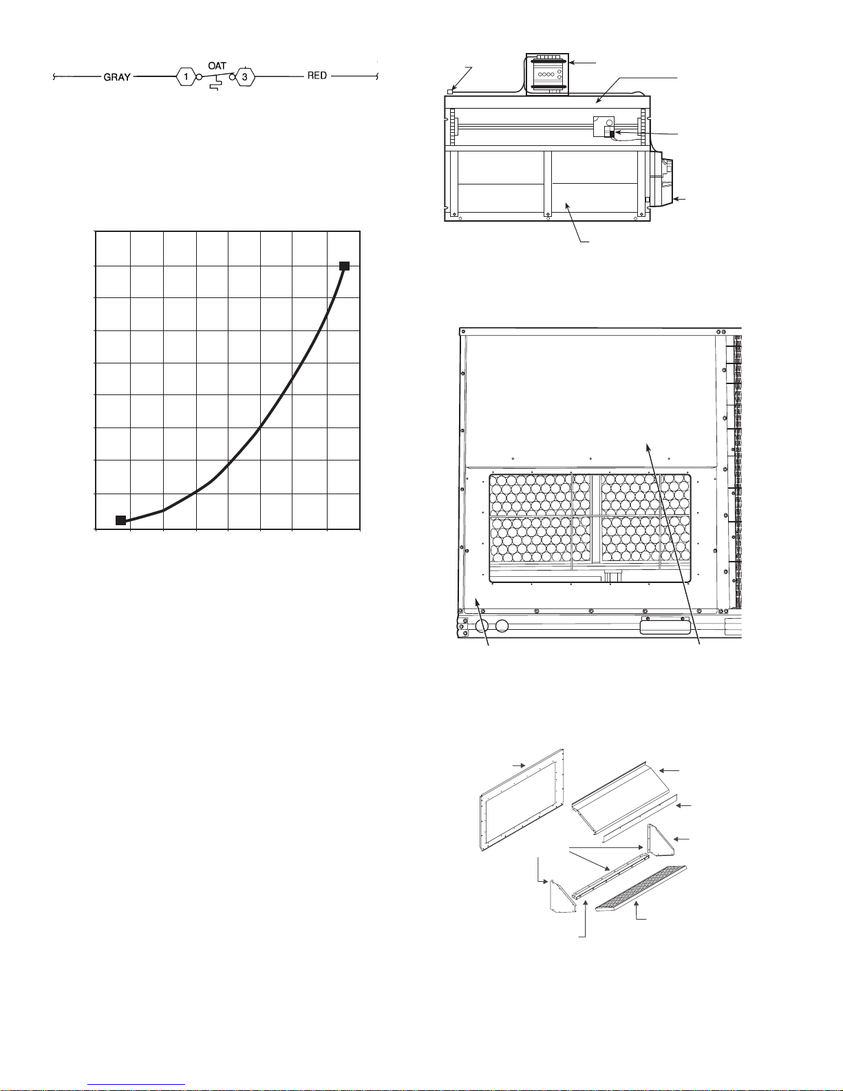
Outdoor-Air Thermostat
ECONOMI$ER
PLUG
CONTROLLER
GEAR-DRIVEN
DAMPER
OUTDOOR AIR
TEMPERATURE
SENSOR
ACTUATOR
0.90
0.80
0.70
0.60
0.50
0.40
0.30
PRESSURE DROP (in. wg)
0.20
0.10
0.00
200 300 400
100
CFM
Fig. 24 — Durablade Economizer
Barometric Relief Damper Characteristics
OPTIONAL ECONOMI$ER — See Fig. 25 for EconoMi$er
component locations.
1. To remove the existing unit filter access panel, raise the
panel and swing the bottom outward. The panel is now
disengaged from the track and can be removed. Remove
the indoor coil access panel and discard. See Fig. 26.
If installing an optional Power Exhaust Assembly, refer to
the EconoMi$er Power Exhaust Installation Instructions.
Controller should be mounted in vertical position as
shown in Fig. 25.
2. Assemble the hood assembly as follows:
Remove the EconoMi$er hood from its packaging. Re-
move shipping brackets holding hood package to
EconoMi$er. Locate the outdoor-air opening panel. See
Fig. 27. Remove hood assembly shipping brackets located on the back (sloped) side of the EconoMi$er assembly.
These brackets are used to retain the hood assembly during shipping only.
3. Installs the
side panels and the bottom bracket. Assemble the exhaust
1
/8 x 3/4-in. seal strip on the exhaust air hood
air hood to the outdoor-air opening panel as shown in
Fig. 27, using the screws provided. Do not attach hood
assembly to unit at this time.
4. Install the
top and side panels. Assemble the outdoor-air hood to the
outdoor-air opening panel as shown in Fig. 28, using the
screws provided. Do not attach hood assembly to the uni t
1
/8 x 3/4-in. seal strip on the outdoor-air hood
at this time.
500 600
700
800
BAROMETRIC RELIEF DAMPERS
Fig. 25 — EconoMi$er Component Locations
OUTDOOR-AIR
OPENING PANEL
FILTER ACCESS
PANEL
14
Page 15
5. Slide the outdoor-air inlet screens into the screen track on
ECONOMI$ER
ECONOMI$ER REAR
FLANGE
UNIT BASE
UNIT FILTER
RACK
ECONOMI$ER CLIP
HVAC UNIT
WIRING
HARNESS
OUTDOOR
AIR
BLOCK-OFF
PLATE
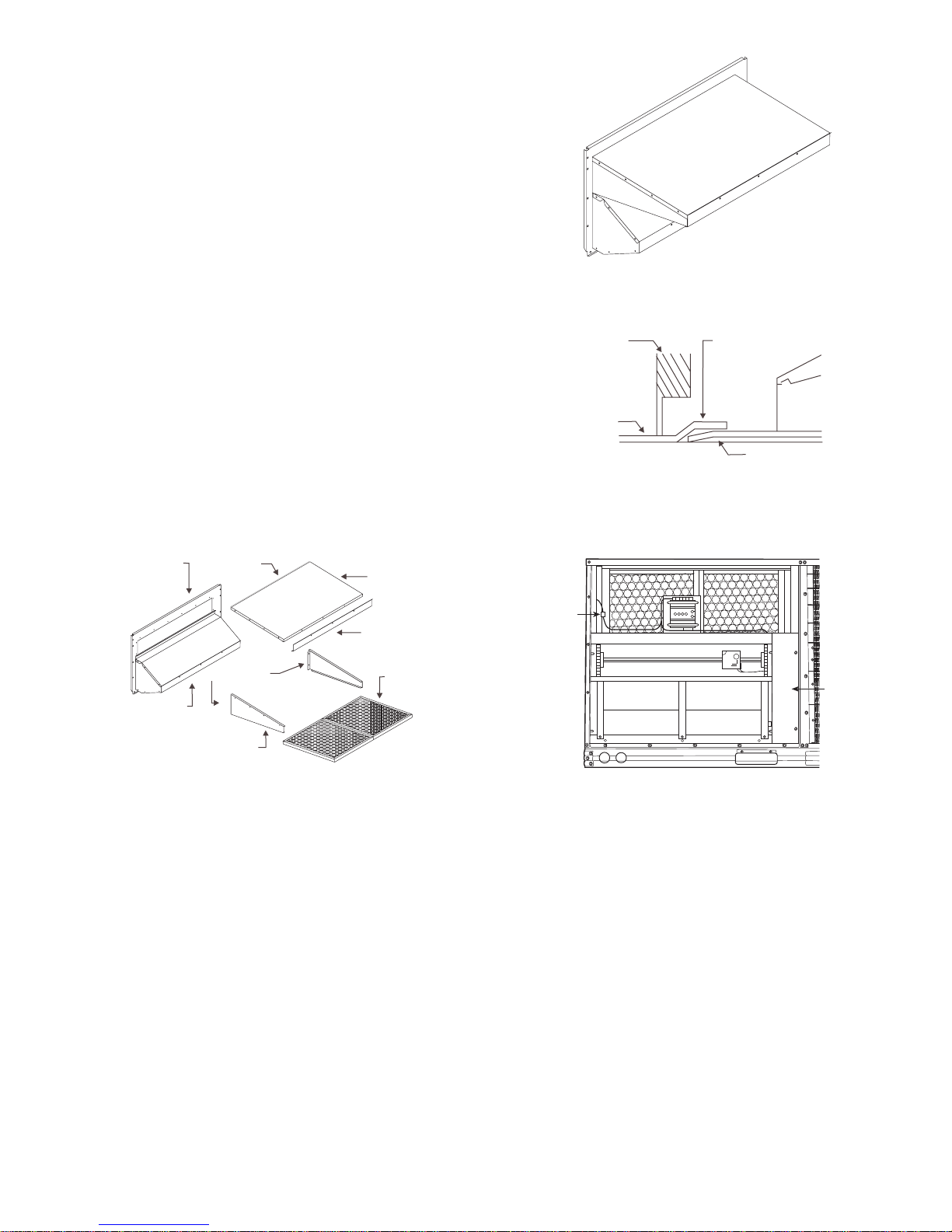
Fig. 29 — Completed Hood Assembly
Fig. 30 — Rear EconoMi$er Flange Installation
Fig. 31 — EconoMi$er Installed
the hood side panels. While holding the screens in place,
fasten the screen retainer to the hood using the screws
provided. Repeat the process for the barometric exhaust
air screen. Do not attach completed (Fig. 29) hood as-
sembly to unit at this time .
6. Slide the EconoMi$er assembly into the rooftop uni t. S ee
Fig. 30 and 31.
NOTE: Be sure to engage rear EconoMi$er flange under
tabs in return-air opening of the unit base. See Fig. 30.
7. Install the outdoor-air block-off plate, then secure the
EconoMi$er with the screws provided. See Fig. 31.
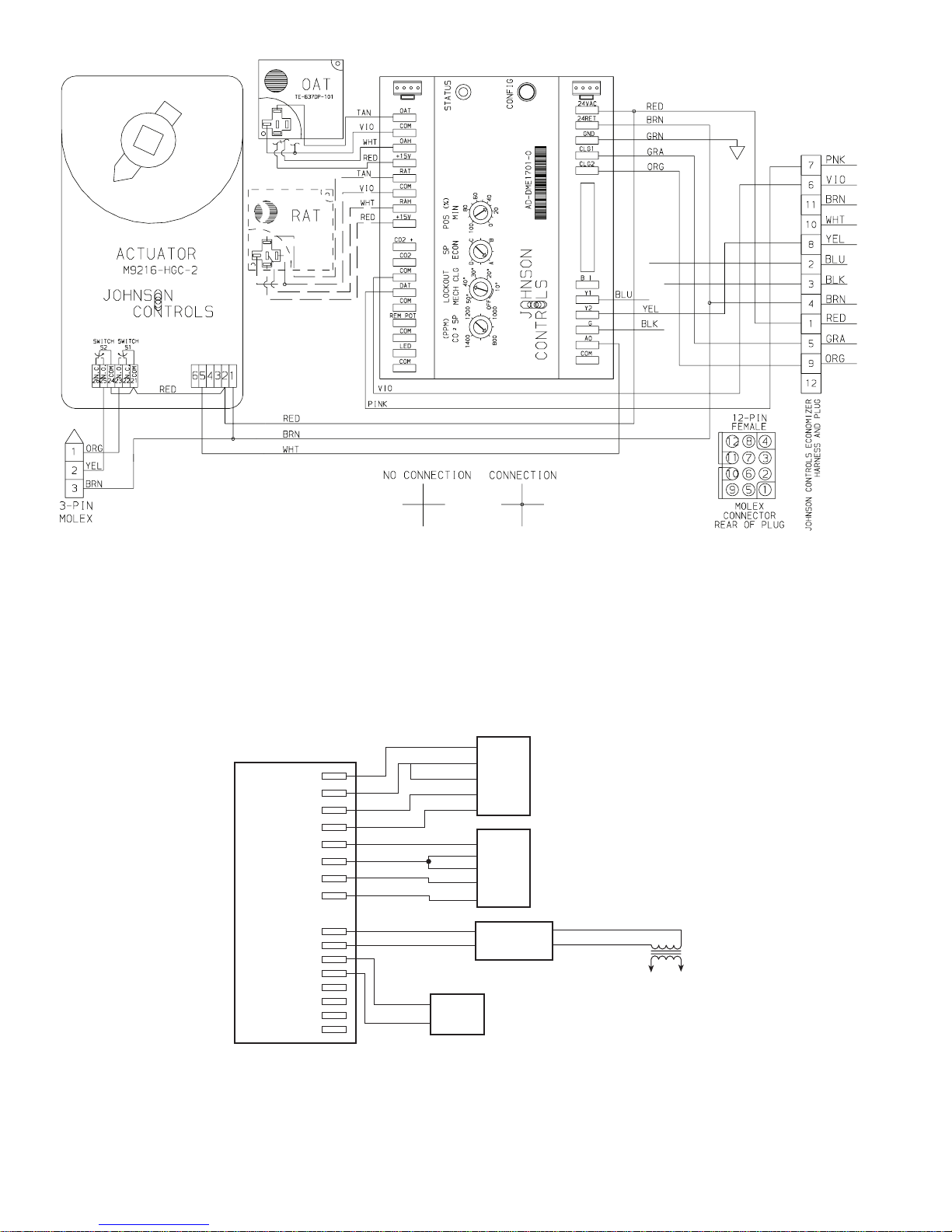
8. Remove and discard the 12-pin jumper plug from the unit
wiring harness located in the upper left corner and insert
the EconoMi$er plug into the unit wiring harness. Refer
to wiring diagram Fig. 32 and 33. Also refer to Fig. 34 if
installing an accessory power exhaust.
9. Install the complete hood assembly on the unit and secure
using the screws provided.
10. Remove the indoor fan motor access panel. See Fig. 35.
11. Mount the supply-air temperature sensor to the lower left
portion of the indoor blower housing with the two (2)
screws provided (see Fig. 36). Connect the violet and
pink wires to the corresponding connections on the
supply-air temperature sensor. Replace the indoor fan
motor access panel.
OUTDOOR AIR
OPENING
PANEL
ASSEMBLED
EXHAUST HOOD
SEAL STRIP
SEAL STRIP
OUTDOOR AIR
HOOD SIDES
Fig. 28 — Outdoor-Air Hood Assembly
OUTDOOR AIR
HOOD TOP
SCREEN
RETAINER
OUTDOOR AIR
INLET
SCREENS
15
Page 16
OAT —
RAT —
LEGEND
Outdoor-Air Tem perature
Return-Air T emper ature
Fig. 32 — EconoMi$er Wiring
ECONOMI$ER
CONTROLLER
OAT
COM
OAH
-15 V
RAT
COM
RAH
+15 V
(+)
CO
2
COM
CO
2
DAT
COM
REM POT
COM
LED
COM
BROWN
VIOLET
WHITE
RED
BROWN
VIOLET
WHITE
RED
SUPPLY AIR
TEMPERATURE SENSOR
PINK
VIOLET
TEMP
TEMP
TEMP
TEMP
COM
OUT
PWR
TEMP
TEMP
COM
OUT
PWR
CO
SENSOR
2
V+
COM VAC
OUTDOOR
AIR
SENSOR
RETURN
AIR
SENSOR
24
Fig. 33 — EconoMi$er Sensor Wiring
16
Page 17
TO FUSED
DISCONNECT
RED
H1
(575 VAC)
HT01AH859
X4
HANDY BOX
X2
X3
SECONDARY
230VAC
2 x 4 IN.
GRAY
H2
X1
GREEN GND
OR
BLACK L1
BLUE L2
RED YELH1BLU
(460 VAC)
HT01AH850
X4
COMPRESSOR 1
CONTACTOR
11 21
23
13
CONNECTOR
L1
1
1
L2
22
GND
33
44
230 VAC
1 PHASE
H3
H2
X3
X2
SECONDARY
230VAC
230VAC
4-PIN
PLUG
GREEN
GRAY
H4
X1
BLACK
BLUE
FIELD SUPPLIED
WIRING
BROWN
C1
GREEN/
YELLOW
BROWN
C1
GREEN/
YELLOW
FAN 1
FAN 2
BLACK
BLACK
LT. BLUE
BLACK
BLUE
BLACK
LT. BLUE
BLACK
3
2
1
3
2
1
6
5
4
BLUE
B
9
8
7
9
6
8
5
4
7
R1
24 VAC
A
B
R2
24 VAC
A
3-PIN
CONNECTOR
PLUG
ORANGE
YELLOW
BROWN
1
2
3
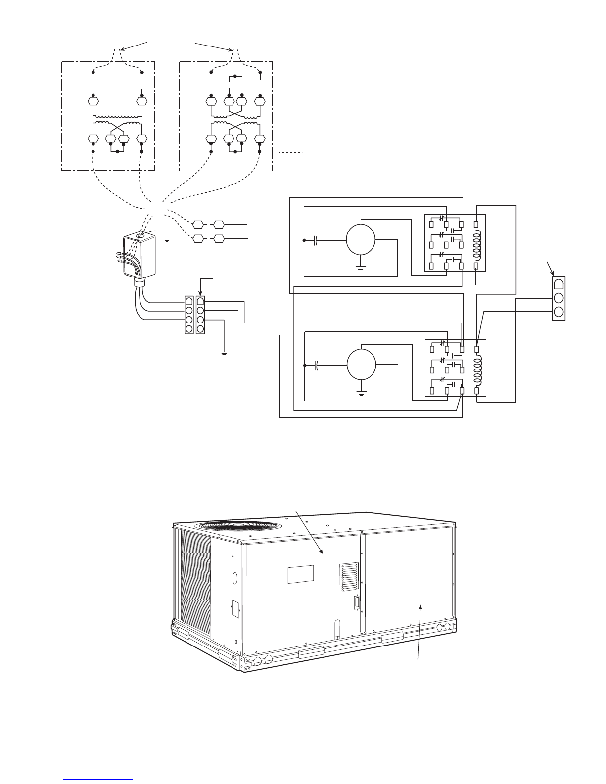
Fig. 34 — Wiring Diagram for Power Exhaust System
CONTROL BOX/BURNER
ACCESS PANEL
INDOOR FAN MOTOR
ACCESS PANEL AND BLOWER
Fig. 35 — Typical Access Panel Locations (Standard Efficiency Unit Shown)
17
Page 18
g
g
SUPPLY AIR
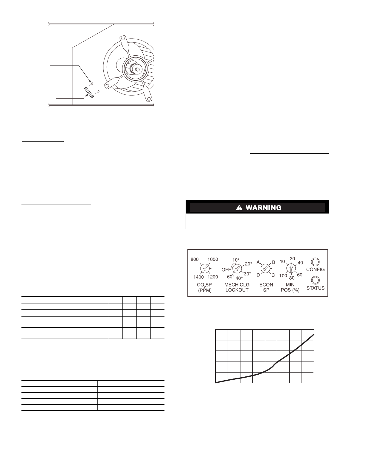
Fig. 37 — EconoMi$er Control Adjustment
Potentiometers (Factory Settings)
Fig. 38 — Barometric Relief Capacity
TEMPERATURE
SENSOR
MOUNTING
LOCATION
SUPPLY AIR
TEMPERATURE
SENSOR
Fig. 36 — Supply-Air Sensor Placement
Control Setup — If a CO2 sensor is not being used, pro-
CO
2
ceed to the next section. If a CO
sensor is being used, perform
2
the following:
1. Determine th e value at which you want the minimum
position of the dampers to begin opening to allow a
greater amount of outdoor air to enter. The range is
800 to 1,400 ppm.
2. Locate the CO
the desired set point. See Fig. 37.
Mechanical Cooling Lockout
SP (PPM) potentiometer and adjust to
2
— Determine the outdoor-air
temperature at which you want the mechanical cooling (compressors) to be disabled. Locate the mechanical cooling lockout
(MECH CLG LOCKOUT) potentiometer. To disable this feature, turn the potentiometer counterclockwise (CCW) to the
OFF position. Otherwise, set the value between 10 and 60 F.
Mechanical cooling will not operate when the outdoor air temperature is below this value. See Fig. 37.
Dry Bulb Changeover Set Up
— Determine the dry bulb
changeover set point from T able 3. The settings are A, B, C and
D. Locate the ECON SP potentiometer and set the dry bulb
changeover set point. See Fig. 37. When the OAT is above this
set point, the damper is limite d to minimum position setting.
Ventilation Air (Minimum Position Set Up)
— If ventilation
air is not required, proceed to Step 5. If ventilation air is required, perform the following:
1. The indoor fan must be on to set the ventilation air.
Either put the thermostat in the continuous fan mode or
jumper the R and G terminals at the rooftop unit connection board.
2. Locat e the minimum p osition (MIN POS ) potent iometer. Turn the potentiometer full CCW to fully close the
outdoor air dampers. Turn the potentiometer gradually
clockwise (CW) to the desired position. See Fig. 37.
3. Replace the filter access panel. See Fig. 26. Ensure the
filter access panel slides along the tracks and is
securely engaged.
4. Calculate the minimum airflow across the
EconoMi$er.
a. Calculate % of outside air using the following
formula.
% Outdoor air through EconoMi$er
% Outdoor air =
Mixture T emp – Return Air Temp
Outdoor T emp – Return Air Temp
b. Divide total CFM by percentage outdoor air, this
gives outdoo r air volume in CFM.
5. Turn on ba se unit power.
NOTE: The EconoMi$er begins operation three min-
utes after power up.
Personal Injury Hazard. Avoid possible injury by keeping fingers away from damper blades.
6. See Fig. 38 for barometric relief damper
characteristics.
Table 3 — Chan
SETTINGS A B C D
Dry Bulb (°F)
Single Enthalpy* (Btu/lb)
Differential Temperature*
(°F , Not Adjustable)
Differential Enthalpy*
(Btu/lb, Not Adjustable)
*Field-installed accessory.
If a potentiometer fails, its setting will default to the values
in T able 4.
eover Set Points
73 69 66 63
27 25 24 22
2222
1111
Table 4 — Default Potentiometer Settin
POTENTIOMETER DEFAULT SETTING
SP (PPM)
CO
2
MECH CLG LOCKOUT
ECON SP
MIN POS (%)
1,000
47°
D
20
0.5
0.4
0.3
0.2
s
0.1
0
STATIC PRESSURE (IN. WG)
200
0
400
FLOW (CUBIC FEET/MINUTE)
600 800 1000
1200
1400 1600
18
Page 19
Step 9 — Adjust Evaporator-F an Speed —
MOTOR MOUNTING
PLATE NUTS
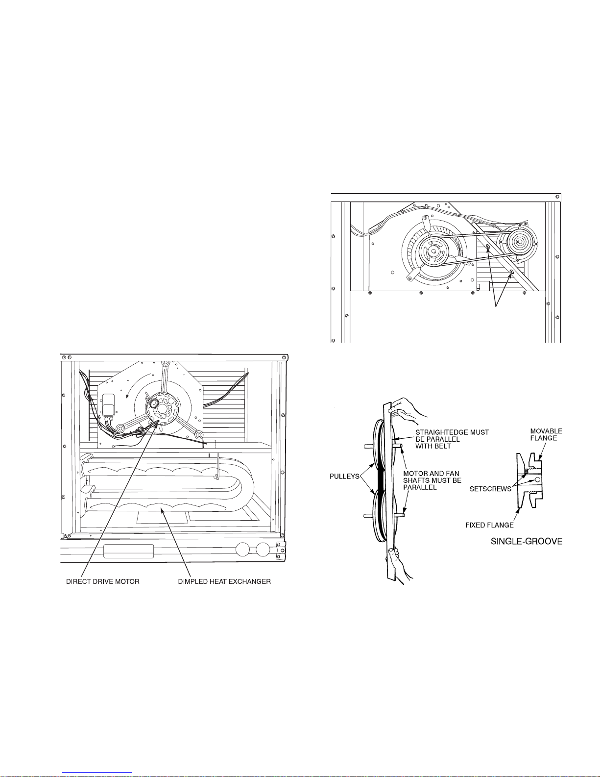
Fig. 40 — Belt Drive Motor Mounting
Fig. 41 — Evaporator-Fan Pulley Adjustment
Adjust evaporator-fan rpm to meet jobsite conditions. Table 5
shows fan rpm at motor pulley settings. Table 6 shows motor
performance. See Table 7 for Accessory/FIOP Static Pressure.
Refer to Tables 8-29 to determine fan speed settings.
DIRECT-DRI VE MOTORS — The evaporator-fan motor
factory speed setting is shown on label diagram affixed to base
unit. If other than factory setting is desired, refer to label
diagram for motor reconnection. See Fig. 39 for direct drive
motor location.
BELT-DRIVE MOTORS — Fan motor pulleys are factory
set for speed shown in table 1. See Fig. 40 for belt drive motor
location.
NOTE: Before adjusting fan speed, make sure the new fan
speed will provide an air temperature rise range as shown in
T able 1.
T o change fan speed:
1. Shut off unit power supply.
2. Loosen belt by loosening fan motor mounting nuts. See
Fig. 40.
3. Loosen movable pulley flange setscrew (see Fig. 41).
4. Screw movable flange toward fixed flange to increase
speed and away from fixed flange to decrease speed. Increasing fan speed increases load on motor. Do not exceed maximum speed specified in Table 1.
5. Set movable flange at nearest keyway of pulley hub and
tighten setscrew. (See Table 1 for speed change for each
full turn of pulley flange.)
T o align fan and motor pulleys:
1. Loosen fan pulley setscrews.
2. Slide fan pulley along fan shaft.
Make angular alignment by loosening motor from
mounting.
T o adjust belt tension:
1. Loosen fan motor mounting nuts.
2. Slide motor mounting plate away from fan scroll for
proper belt tension (
1
/2-in. deflection with one finger).
3. T ight en motor mounting nuts.
4. Adjust bolt and tighten nut to secure motor in fixed
position.
Fig. 39 — Direct Drive Motor Mounting
19
Page 20
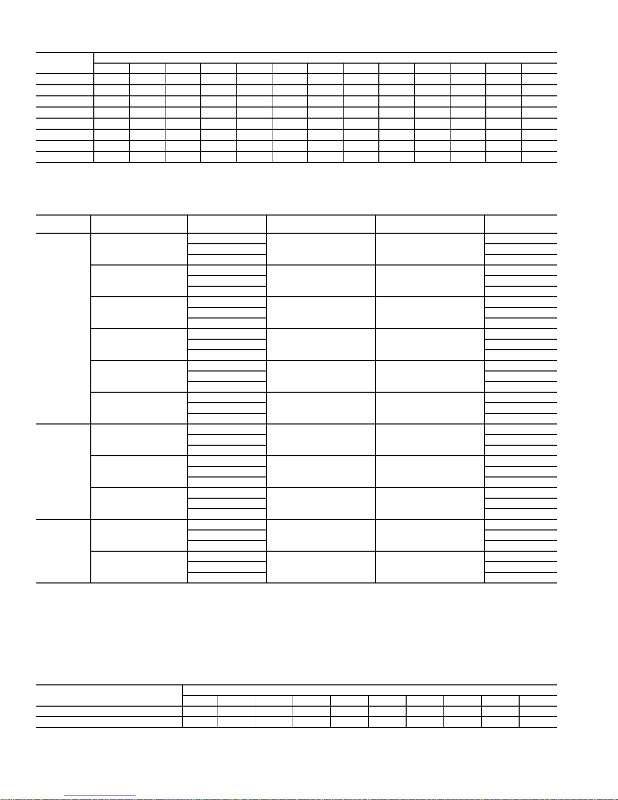
Table 5 — Fan Rpm at Motor Pulley Settings*
UNIT
48TF
004†
004**
005†
005**
006†
006**
007††
007**
*Approximate fan rpm shown.
†Indicates alternate motor and drive package.
0
1000 976 952 928 904 880 856 832 808 784 760 — —
1455 1423 1392 1360 1328 1297 1265 1233 1202 1170 1138 1107 1075
1185 1150 1115 1080 1045 1010 975 940 905 870 835 — —
1455 1423 1392 1360 1328 1297 1265 1233 1202 1170 1138 1107 1075
1300 1260 1220 1180 1140 1100 1060 1020 980 940 900 — —
1685 1589 1557 1525 1493 1460 1428 1396 1364 1332 1300 — —
1460 1420 1380 1345 1305 1265 1225 1185 1150 1110 1070 — —
1685 1589 1557 1525 1493 1460 1428 1396 1364 1332 1300 — —
1
/
2
11
1
/
2
22
Table 6 — Motor Data
UNIT
48TF
004
005
006
007
LEGEND
Brake Horsepower
BHP —
*Extensive motor and electrical testing on these units ensures that the
full horsepower range of the motors can be utilized with confidence.
Using your fan motors up to the horsepower ratings shown in this table
will not result in nuisance tripping or premature motor failure. Unit warranty will not be affected.
†Single phase/three-phase.
EVAPORATOR-FAN
MOTOR
Standard
Alternate
High Static
Standard
Alternate
High Static
Standard
Alternate
High Static
Standard
High Static
UNIT
VOLTAGE
208/230
460 1.3
575 1.3
208/230
460 2.1
575 2.1
208/230
460 3.0
575 3.0
208/230
460 1.8
575 1.8
208/230
460 2.1
575 2.1
208/230
460 3.0
575 3.0
208/230
460 3.2
575 3.2
208/230
460 3.0
575 3.0
208/230
460 3.9
575 3.9
208/230
460 3.0
575 3.0
208/230
460 3.9
575 3.9
MOTOR PULLEY TURNS OPEN
1
/
MAXIMUM ACCEPTABLE
CONTINUOUS BHP*
33
2
**Indicates high-static motor and drive package .
††Indicates standard motor and drive packag e.
1
/
2
0.34 440
1.00 1000
2.40 2120
0.75 850
1.00 1000
2.40 2120
1.20 1340
1.30/2.40† 2120
2.90 2562
2.40 2120
2.90 2562
NOTES:
1. All indoor-fan motors 5 hp and larger meet the minimum efficiency
requirements as established by the Energy Policy Act of 1992
(EPACT) effective October 24, 1997.
2. High-static motor not available on single-phase units.
44
MAXIMUM ACCEPTABLE
OPERATING WATTS
1
/
2
55
1
/
2
MAXIMUM
AMP DRAW
2.8
4.9
6.0
3.5
4.9
6.0
5.9
10.1/6.7†
8.6
6.7
8.6
6
Table 7 — Accessory/FIOP Static Pressure* (in. wg) — 48TF004-007
COMPONENT
Durablade Economizer
EconoMi$er
LEGEND
Factory-Installed Option
FIOP —
900 1200 1400 1600 1800 2000 2200 2400 2600 3000
0.05 0.05 0.05 0.05 0.05 0.05 0.05 0.05 0.05 0.05
0.05 0.09 0.13 0.17 0.22 0.27 0.32 0.39 0.45 0.53
CFM
*The static pressure must be added to external static pressure. The sum
and the evaporator entering-air cfm should then be used in conjunction
with the Fan Performance tables to determine blower rpm and watts.
20
Page 21
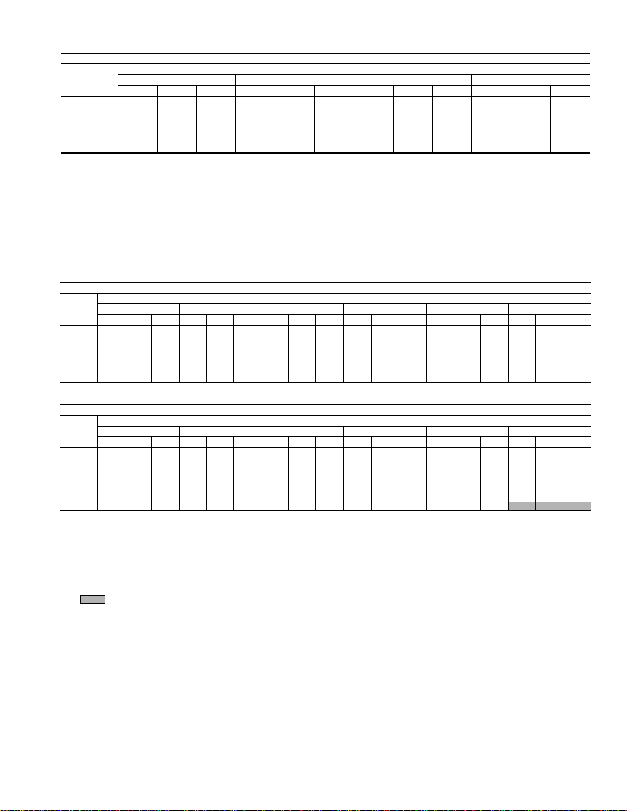
Table 8 — Fan Performance 48TF004 — Vertical Discharge Units, Standard Motor
48TF004 (3 TONS) — STANDARD MOTOR (DIRECT DRIVE)
Airflow
(Cfm)
900
1000
1100
1200
1300
1400
1500
LEGEND
Bhp —
Esp —
FIOP —
NOTES:
1. Values include losses for filters, unit casing, and wet coils. See
Brake Horsepo wer Input to Fan
External Static Pressure (in. wg)
Factory-Installed Option
Table 7 for accessory/FIOP static pressure information.
Esp Bhp Watts Esp Bhp Watts Esp Bhp Watts Esp Bhp Watts
0.49 0.21 253 0.50 0.23 277 0.51 0.26 307 0.55 0.31 363
0.42 0.23 270 0.43 0.25 292 0.43 0.27 321 0.51 0.32 374
0.37 0.24 287 0.38 0.26 307 0.39 0.28 335 0.46 0.33 385
0.33 0.26 304 0.33 0.27 323 0.34 0.29 349 0.40 0.34 397
0.27 0.27 321 0.28 0.29 338 0.28 0.31 364 0.34 0.34 408
0.20 0.29 338 0.23 0.30 354 0.25 0.32 378 — — —
0.16 0.30 355 0.18 0.31 369 0.20 0.33 392 — — —
208 V 230, 460, 575 V 208 V 230, 460, 575 V
Low Speed High Speed
Table 9 —Fan Performance 48TF004 — Vertical Discharge Units, Alternate Motor
48TF004 (3 TONS) — ALTERNATE MOTOR (BELT DRIVE)*
Airflow
(Cfm)
1000 644 0.19 189 709 0.22 219
1100 687 0.22 219 746 0.26 259
1200 733 0.26 259
1300 754 0.29 288
1400
1500
Rpm Bhp Watts Rpm Bhp Watts Rpm Bhp Watts Rpm Bhp Watts Rpm Bhp Watts Rpm Bhp Watts
900 581 0.12 119 673 0.18 179 736 0.22 219
0.1 0.2 0.3 0.4 0.5 0.6
785 0.32 318 843 0.35 348 903 0.41 408 960 0.47 467 994 0.50 497
810 0.35 348 868 0.45 448 937 0.51 507 984 0.57 567
841 0.42 418 911 0.53 527 985 0.61 607
826 0.38 378 891 0.43 428 942 0.48 477 991 0.53 527
External Static Pressure (in. wg)
782 0.28 279 835 0.30 298 900 0.35 348 937 0.38 378
806 0.30 298 867 0.35 348 929 0.40 398 964 0.40 398
2. Extensive motor and electrical testing on these units ensures that
the full range of the motor can be utilized with confidence. Using
your fan motors up to the wattage ratings shown will not result in
nuisance tripping or premature motor failure. Unit warranty will not
be affected. See Table 6 — Motor Data for additional information.
3. Use of a field-supplied motor may affect wire sizing. Contact your
Carrier representative for details.
805 0.25 249 865 0.29 288 911 0.34 338
1029 0.66 656 1073 0.72 716 1109 0.77 766
1032 0.62 617 1067 0.67 666
1047 0.60 597
48TF004 (3 TONS) — ALTERNATE MOTOR (BELT DRIVE)* (cont)
Airflow
(Cfm)
1000
1100 1013 0.49 487 1068 0.55 547 1091 0.61 577 1109 0.66 607 1127 0.73 637 1145 0.80 666
1200 1045 0.56 557 1090 0.64 637 1109 0.68 647 1156 0.73 676 1203 0.81 706 1250 0.86 736
1300 1075 0.64 637 1122 0.70 696 1152 0.76 716 1190 0.82 756 1228 0.87 796 1266 0.94 836
1400 1110 0.73 726 1160 0.78 766 1181 0.83 806 1237 0.88 845 1293 0.94 885 1349 0.99 925
1500 1150 0.78 816 1190 0.84 855 1225 0.89 895 1271 0.95 945 1317 1.00 995
LEGEND
Bhp —
FIOP —
Watts —
*Motor drive range is 760 to 1000 rpm. All other rpms require a field-
supplied drive.
NOTES:
1.
2. indicates field-supplied motor and driv e are required.
Rpm Bhp Watts Rpm Bhp Watts Rpm Bhp Watts Rpm Bhp Watts Rpm Bhp Watts Rpm Bhp Watts
900
Brake Horsepower Input to Fan
Factory-Installed Option
Input Watts to Motor
Boldface
0.7 0.8 0.9 1.0 1.1 1.2
957 0.39 388 988 0.43 428
992 0.44 438
indicates field-supplied drive is required.
1039 0.49 487 1061 0.55 507 1088 0.60 547 1111 0.66 587 1136 0.72 627
External Static Pressure (in. wg)
1039 0.47 448 1061 0.51 487 1083 0.54 527 1105 0.58 567
1383 1.05 1044
3. Values include losses for filters, unit casing, and wet coils. See
Table 7 for accessory/FIOP static pressure information.
4. Maximum continuous bhp is 1.0 and the maximum continuous
watts are 1000. Extensive motor and electrical testing on these
units ensures that the full range of the motor can be utilized with
confidence. Using your fan motors up to the wattage ratings shown
will not result in nuisance tripping or premature motor failure. Unit
warranty will not be affected. See Table 6 — Motor Data for additional information.
5. Use of a field-supplied motor may affect wire sizing. Contact your
Carrier representative for details.
6. Interpolation is permissible . Do not extrapola te.
21
Page 22
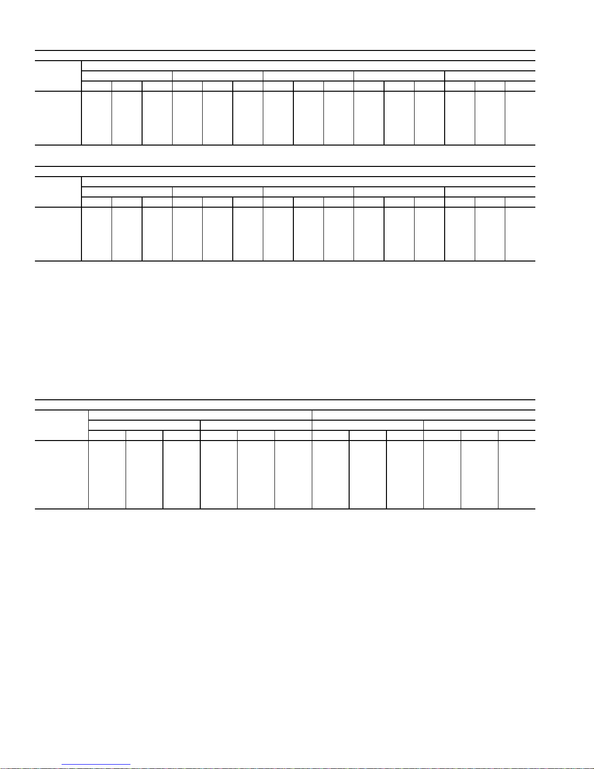
Table 10 — Fan Performance 48TF004 — Vertical Discharge Units, High-Static Motor
48TF004 (3 TONS) — HIGH-STATIC MOTOR (BELT DRIVE)*
Airflow
(Cfm)
900 673 0.18 179 805 0.25 249 911 0.34 338 988 0.43 428 1061 0.47 487
1000 709 0.22 219 835 0.30 298 937 0.38 378 1039 0.49 487
1100 746 0.26 259 867 0.35 348 964 0.40 398 1068 0.55 547
1200 785 0.32 318 903 0.41 408 994 0.50 497
1300 826 0.38 378 942 0.48 477 1047 0.60 597
1400 868 0.45 448 984 0.57 567 1067 0.67 666
1500 911 0.53 527 1029 0.66 656
48TF004 (3 TONS) — HIGH-STATIC MOTOR (BELT DRIVE)* (cont)
Airflow
(Cfm)
900
1000
1100
1200
1300
1400
1500
LEGEND
Bhp —
FIOP —
Watts —
*Motor drive range is 1075 to 1455 rpm. All other rpms require a field-
supplied drive.
NOTES:
1.
Boldface
2. Values include losses for filters, unit casing, and wet coils. See
Table 7 for accessory/FIOP static pressure information.
Rpm Bhp Watts Rpm Bhp Watts Rpm Bhp Watts Rpm Bhp Watts Rpm Bhp Watts
Rpm Bhp Watts Rpm Bhp Watts Rpm Bhp Watts Rpm Bhp Watts Rpm Bhp Watts
1105 0.57 567 1140 0.63 622 1170 0.68 674 1198 0.73 723 1224 0.77 771
1136 0.63 627 1172 0.69 688 1203 0.75 745 1232 0.80 799 1258 0.86 852
1145 0.67 666 1181 0.73 731 1213 0.80 792 1242 0.85 850 1268 0.91 906
1210 0.74 736 1248 0.81 808 1282 0.88 875 1312 0.94 939 1340 1.01 1000
1266 0.84 836 1306 0.92 917 1341 1.00 993 1373 1.07 1066 1402 1.14 1136
1349 0.93 925 1391 1.02 1015 1492 1.11 1100
1383 1.05 1044 1426 1.15 1146
Brake Horsepower Input to Fan
Factory-Installed Option
Input Watts to Motor
indicates field-supplied drive is required.
0.2 0.4 0.6 0.8 1.0
1.2 1.4 1.6 1.8 2.0
External Static Pressure (in. wg)
1086 0.55 547
1090 0.64 637 1156 0.68 676
1122 0.70 696 1190 0.76 756
1109 0.77 766 1190 1.00 855 1271 0.95 945
External Static Pressure (in. wg)
1465 1.25 1242 1500 1.34 1332 1532 1.43 1419
3. Maximum continuous bhp is 2.4 and the maximum continuous
watts are 2120. Extensive motor and electrical testing on these
units ensures that the full range of the motor can be utilized with
confidence. Using your fan motors up to the wattage ratings shown
will not result in nuisance tripping or premature motor failure. Unit
warranty will not be affected. See Table 6 — Motor Data for additional information.
4. Use of a field-supplied motor may affect wire sizing. Contact your
Carrier representative for details.
5. Interpolation is permissible . Do not extrapola te.
1160 0.84 766 1237 0.85 845
1463 1.19 1180 1494 1.26 1257
1109 0.61 607
Table 11 — Fan Performance 48TF005 — Vertical Discharge Units, Standard Motor
48TF005 (4 TONS) — STANDARD MOTOR (DIRECT DRIVE)
Airflow
(Cfm)
1200
1300
1400
1500
1600
1700
1800
1900
2000
LEGEND
Bhp —
Esp —
FIOP —
NOTES:
Brake Horsepower Input to Fan
External Static Pressure (in. wg)
Factory-Installed Option
1. Values include losses for filters, unit casing, and wet coils. See
Table 7 for accessory/FIOP static pressure information.
Esp Bhp Watts Esp Bhp Watts Esp Bhp Watts Esp Bhp Watts
0.68 0.41 458 0.74 0.45 506 0.74 0.51 572 0.85 0.56 632
0.61 0.42 471 0.67 0.46 521 0.66 0.52 589 0.78 0.58 651
0.53 0.45 503 0.59 0.49 556 0.59 0.54 616 0.70 0.60 681
0.45 0.47 536 0.51 0.52 593 0.52 0.56 631 0.63 0.62 698
0.36 0.49 557 0.42 0.54 616 0.45 0.58 654 0.56 0.64 723
0.26 0.52 584 0.32 0.57 646 0.37 0.60 678 0.48 0.66 750
0.15 0.54 610 0.22 0.60 674 0.30 0.62 698 0.41 0.68 772
0.04 0.56 629 0.11 0.62 696 0.23 0.64 720 0.34 0.70 796
——————0.160.667440.260.73823
208 V 230, 460, 575 V 208 V 230, 460, 575 V
Low Speed High Speed
2. Extensive motor and electrical testing on these units ensures that
the full range of the motor can be utilized with confidence. Using
your fan motors up to the wattage ratings shown will not result in
nuisance tripping or premature motor failure. Unit warranty will not
be affected. See Table 6 — Motor Data for additional information.
3. Use of a field-supplied motor may affect wire sizing. Contact your
Carrier representative for details.
22
Page 23
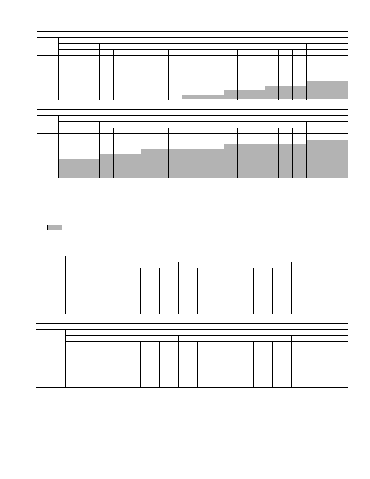
Table 12 — Fan Performance 48TF005 — Vertical Discharge Units, Alternate Motor
48TF005 (4 TONS) — ALTERNATE MOTOR (BELT DRIVE)*
Airflow
(Cfm)
1200 596 0.20 210 665 0.25 263 722 0.31 320 779 0.36 378 872 0.48 504 915 0.54 567 957 0.60 630
1300 633 0.24 252 699 0.30 315 754 0.36 378 809 0.42 441 902 0.55 578 943 0.61 641 984 0.67 704
1400 6720.303157350.36378 7880.42441 840 0.48 504 933 0.62 651 972 0.69 720 1011 0.75 788
1500 7110.353687700.42441 8220.49510 873 0.55 578 963 0.69 725 1002 0.77 804 1041 0.84 858
1600 751 0.42 441 835 0.49 515 871 0.56 588 907 0.63 662 993 0.77 787 1033 0.85 869 1072 0.93 950
1700 791 0.49 515 873 0.57 599 907 0.65 678 941 0.72 757 1024 0.87 889 1064 0.96 976
1800 831 0.58 609 881 0.66 693 929 0.74 772 976 0.81 851 1057 0.97 991
1900 872 0.67 704 919 0.75 788 965 0.84 877 1011 0.92 967
2000 913 0.77 809 958 0.86 904 1002 0.95 993
0.1 0.2 0.3 0.4 0.6 0.7 0.8
Rpm Bhp Watts Rpm Bhp Watts Rpm Bhp Watts Rpm Bhp Watts Rpm Bhp Watts Rpm Bhp Watts Rpm Bhp Watts
External Static Pressure (in. wg)
1046 1.03 1082 1125 1.21 1237 1160 1.30 1323 1195 1.38 1410
1091 1.08 1104 1127 1.17 1191 1162 1.25 1277
1095 1.06 1078 1132 1.14 1165
1103 1.04 1063
48TF005 (4 TONS) — ALTERNATE MOTOR (BELT DRIVE)* (cont)
Airflow
(Cfm)
1200 993 0.65 678 1028 0.69 725 1056 0.72 751 1083 0.74 778 1134 0.80 935 1185 0.88 965 1331 0.99 1000
1300 1021 0.74 772 1058 0.80 841 1090 0.85 888 1121 0.89 935 1171 0.94 988 1219 1.00 999
1400 1049 0.82 837 1086 0.89 885 1120 0.96 950 1153 1.00 976
1500 1077 0.92 922 1113 0.99 985
1600 1107 1.00 998
1700
1800
1900
2000
LEGEND
Bhp — Brake Horsepower Input to Fan
FIOP — Factory-Installed Option
Watts — Input Watts to Motor
*Motor drive range is 8 35 to 11 85 r pm. All o ther r p ms requ ire a fi eld-sup plied
drive.
NOTES:
1. Bol dface indicates field-supplied drive is required.
2. indicates field-supplied motor and drive are required.
0.9 1.0 1.1 1.2 1.4 1.6 1.8
Rpm Bhp Watts Rpm Bhp Watts Rpm Bhp Watts Rpm Bhp Watts Rpm Bhp Watts Rpm Bhp Watts Rpm Bhp Watts
1137 1.12 1128 1171 1.20 1194 1203 1.29 1278 1235 1.37 1310 1296 1.53 1463 1354 1.70 1605 1407 1.84 1738
1167 1.23 1239 1202 1.32 1313 1233 1.41 1398 1263 1.49 1425 1323 1.67 1597 1381 1.85 1747 1436 2.02 1907
1197 1.35 1360 1232 1.45 1442 1263 1.54 1532 1294 1.63 1559 1351 1.81 1731 1408 2.00 1889 1463 2.19 2068
1229 1.48 1491 1262 1.58 1572 1294 1.68 1671 1325 1.78 1702 1362 1.97 1884 1436 2.16 2040 1489 2.36 2229
1141 1.09 1084 1174 1.17 1134 1207 1.25 1196 1269 1.40 1339 1326 1.54 1454 1376 1.65 1558
1147 1.06 1054 1180 1.13 1081 1241 1.27 1215 1295 1.37 1294 1339 1.43 1350
External Static Pressure (in. wg)
1210 1.12 1071 1257 1.17 1105 1307 1.25 1190
3. Values include losses for filters, un it casing , and wet coils. See Table 7
for accessory/FIOP static pressure information.
4. Maximum continuous bhp is 1.0 and th e ma ximum continuo us wa tts ar e
1000. Extensive motor and ele ctr i ca l testi n g o n th ese units ensures that
the full range of t he motor can be ut ilized with confiden ce. Using your
fan motors up to the wattage ratings sh own will not result in nuisance
tripping or premature motor failure. Unit warranty will not be affected.
See Table 6 — Motor Data for additional information.
5. Use of a field-supplied motor may affect wire sizing. Contact your
Carrier representative for details.
6. Interpolation is permissible. Do not extrapolate.
1268 1.10 1029
Table 13 — Fan Performance 48TF005 — Vertical Discharge Units, High-Static Motor
48TF005 (4 TONS) — HIGH-STATIC MOTOR (BELT DRIVE)*
Airflow
(Cfm)
1200 665 0.25 263 779 0.36 378 872 0.48 504 957 0.60 630 1028 0.69 725
1300 699 0.30 315 809 0.42 441 902 0.55 578 984 0.67 704 1058 0.80 841
1400 735 0.36 378 840 0.48 504 933 0.62 651 1011 0.75 788 1086 0.89 885
1500 770 0.42 441 873 0.55 578 963 0.69 725 1041 0.84 858 1113 0.99 985
1600 835 0.49 515 907 0.63 662 993 0.77 787 1072 0.93 950 1141 1.09 1084
1700 873 0.57 599 941 0.72 757 1024 0.87 889 1103 1.04 1063 1171 1.20 1194
1800 881 0.66 693 976 0.81 851 1057 0.97 991 1132 1.14 1165 1202 1.32 1313
1900 919 0.75 788 1011 0.92 967 1091 1.08 1104 1162 1.25 1277 1232 1.45 1442
2000 958 0.86 904 1046 1.03 1082 1125 1.21 1237 1195 1.38 1410 1262 1.58 1572
48TF005 (4 TONS) — HIGH-STATIC MOTOR (BELT DRIVE)* (cont)
Airflow
(Cfm)
1200 1083 0.74 778 1134 0.80 935 1185 0.88 965 1331 0.99 1000 1374 1.09 1083
1300 1121 0.89 935 1171 0.94 988 1219 1.00 999 1268 1.10 1029 1309 1.21 1203
1400 1153 1.00 967 1210 1.12 1071 1257 1.17 1105 1307 1.25 1190 1349 1.37 1367
1500 1180 1.13 1081 1241 1.27 1215 1295 1.37 1294 1339 1.43 1350 1382 1.57 1564
1600 1207 1.25 1196 1269 1.40 1339 1326 1.54 1454 1376 1.65 1558 1420 1.81 1805
1700 1235 1.37 1310 1296 1.53 1463 1354 1.70 1605 1407 1.84 1738 1452 2.02 2013
1800 1263 1.49 1425 1323 1.67 1597 1381 1.85 1747 1436 2.02 1907 1482 2.22 2210
1900 1294 1.63 1559 1351 1.81 1731 1408 2.00 1889 1463 2.19 2068 ———
2000 1325 1.78 1702 1362 1.97 1894 1436 2.16 2040 1489 2.36 2229 ———
LEGEND
Bhp — Brake Horsepower Input to Fan
FIOP — Factory-Installed Option
Watts — Input Watts to Motor
*Motor drive range is 1075 to 1455 rpm. All other rpms require a field-
supplied drive.
NOTES:
1. Boldface indicates field-supplied drive is required.
2. Values include losses for filters, unit casing, and wet coils. See Table 7
for accessory/FIOP static pressure information.
Rpm Bhp Watts Rpm Bhp Watts Rpm Bhp Watts Rpm Bhp Watts Rpm Bhp Watts
Rpm Bhp Watts Rpm Bhp Watts Rpm Bhp Watts Rpm Bhp Watts Rpm Bhp Watts
0.2 0.4 0.6 0.8 1.0
1.2 1.4 1.6 1.8 2.0
External Static Pressure (in. wg)
External Static Pressure (in. wg)
3. Maximum continuous bhp is 2.4 and th e ma ximum continuo us wa tts ar e
2120. Extensive motor and ele ctr i ca l testi n g o n th ese units ensures that
the full range of t he motor can be ut ilized with confiden ce. Using your
fan motors up to the wattage ratings sh own will not result in nuisance
tripping or premature motor failure. Unit warranty will not be affected.
See Table 6 — Motor Data for additional information.
4. Use of a field-supplied motor may affect wire sizing. Contact your
Carrier representative for details.
5. Interpolation is permissible . Do not extrapola te.
23
Page 24
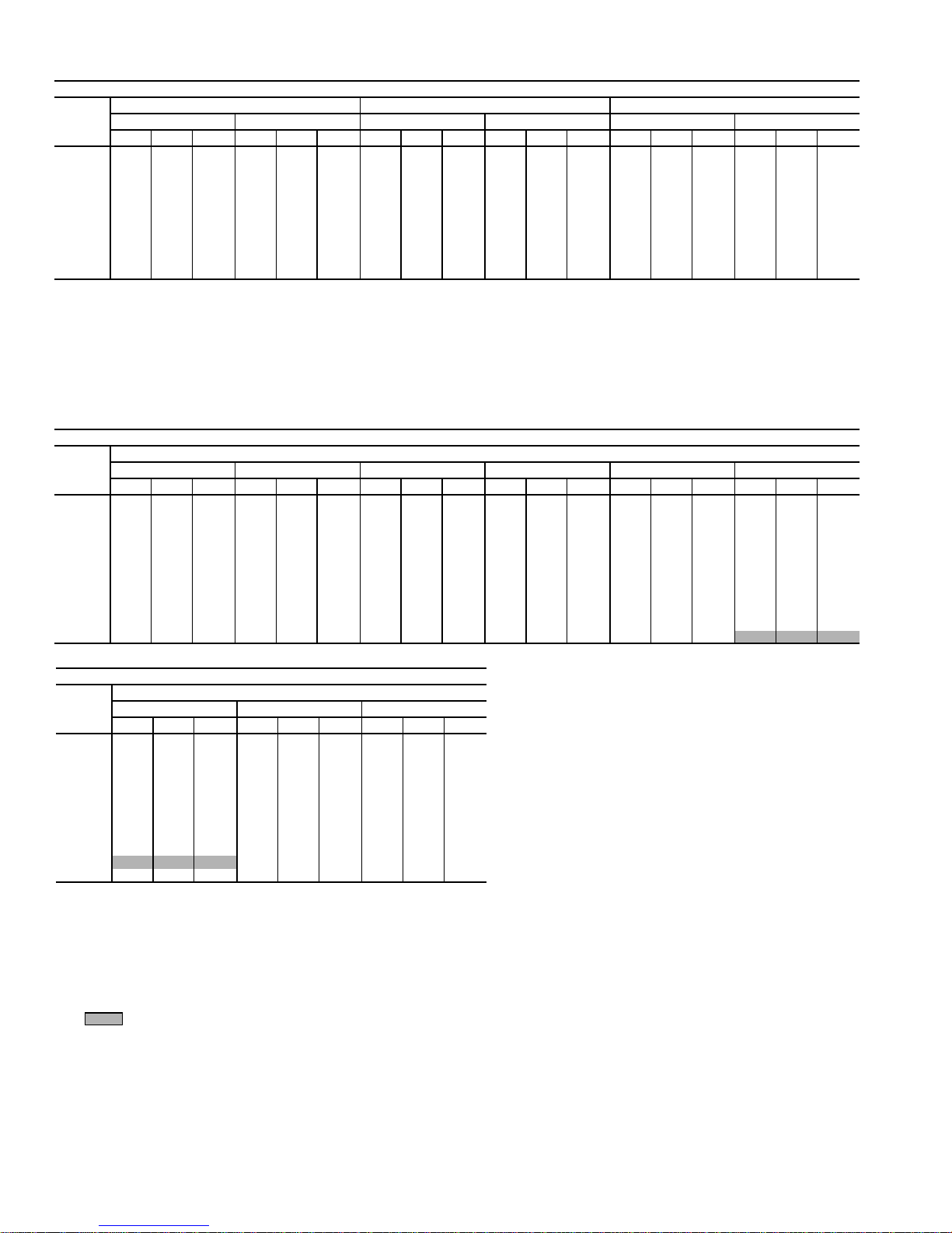
Table 14 — Fan Performance 48TF006 — Vertical Discharge Units, Standard Motor
48TF006 (5 TONS) — STANDARD MOTOR (DIRECT DRIVE)
Airflow
(Cfm)
1500
1600
1700
1800
1900
2000
2100
2200
2300
2400
2500
LEGEND
Bhp —
Esp —
FIOP —
NOTES:
1. Values include losses for filters, unit casing, and wet coils. See
Table 7 for accessory/FIOP static pressure information.
208 V 230,460,575 V 208 V 230,460,575 V 208 V 230,460,575 V
Esp Bhp Watts Esp Bhp Watts Esp Bhp Watts Esp Bhp Watts Esp Bhp Watts Esp Bhp Watts
0.69 0.67 750 1.01 0.71 791 1.00 0.70 782 1.20 0.76 845 1.22 0.79 875 1.28 0.85 949
0.49 0.70 780 0.85 0.74 824 0.85 0.74 821 1.06 0.79 883 1.09 0.82 913 1.17 0.89 988
0.29 0.73 810 0.70 0.77 857 0.70 0.77 861 0.93 0.83 921 0.97 0.85 950 1.06 0.92 1027
0.09 0.75 839 0.54 0.80 891 0.55 0.81 900 0.80 0.86 959 0.84 0.89 988 0.95 0.96 1066
— — — 0.39 0.83 924 0.40 0.84 940 0.67 0.90 997 0.72 0.92 1025 0.84 0.99 1105
— — — 0.23 0.86 957 0.25 0.88 979 0.54 0.93 1035 0.59 0.95 1063 0.73 1.03 1144
— — — 0.08 0.89 990 0.10 0.91 1018 0.41 0.96 1073 0.46 0.99 1101 0.62 1.06 1183
— — — — — — — — — 0.28 1.00 1111 0.34 1.02 1138 0.51 1.10 1222
— — — — — — — — — 0.15 1.03 1149 0.21 1.06 1176 0.40 1.13 1261
— — — — — — — — — 0.02 1.07 1187 0.09 1.09 1213 0.29 1.17 1300
———————————————0.181.201340
Brake Horsepo wer Input to Fan
External Static Pressure (in. wg)
Factory-Installed Option
Low Speed Medium Spee d High Speed
Table 15 — Fan Performance 48TF006 — Vertical Discharge Units, Alternate Motor
48TF006 (5 TONS) — ALTERNATE MOTOR (BELT DRIVE)*
Airflow
(Cfm)
1500 729 0.36 368 788 0.42 429 896 0.56 572
1600 770 0.42 429 826 0.49 501
1700 811 0.50 511 864 0.57 582
1800 852 0.58 593
1900 893 0.68 695
2000
2100
2200
2300
2400
2500
1019 1.02 1042 1063 1.12 1145 1144 1.30 1328 1222 1.49 1523 1294 1.70 1737
1061 1.16 1185 1104 1.26 1288 1182 1.47 1502 1258 1.65 1686
1103 1.30 1328 1145 1.41 1441 1220 1.61 1645 1293 1.80 1860
1145 1.46 1492 1186 1.57 1604 1259 1.78 1819
0.1 0.2 0.4 0.6 0.8 1.0
Rpm Bhp Watts Rpm Bhp Watts Rpm Bhp Watts Rpm Bhp Watts Rpm Bhp Watts Rpm Bhp Watts
903 0.66 674 999 0.82 838 1085 0.98 1001 1155 1.13 1155 1231 1.32 1349
942 0.76 777 1035 0.92 940 1119 1.10 1124 1191 1.26 1288 1288 1.43 1461
935 0.78 797 982 0.87 889 1070 1.04 1063 1153 1.22 1247 1227 1.40 1431 1287 1.57 1604
977 0.89 910 1022 0.99 1012 1107 1.17 1196 1187 1.35 1380 1260 1.54 1574
External Static Pressure (in. wg)
930 0.64 654 1015 0.78 797 1098 0.94 961 1173 1.11 1134
964 0.72 736 1051 0.88 899 1124 1.03 1053 1203 1.21 1237
2. Extensive motor and electrical testing on these units ensures that
the full range of the motor can be utilized with confidence. Using
your fan motors up to the wattage ratings shown will not result in
nuisance tripping or premature motor failure. Unit warranty will not
be affected. See Table 6 — Motor Data for Additional information.
3. Use of a field-supplied motor may affect wire sizing. Contact your
Carrier representative for details.
981 0.69 705 1070 0.85 869 1144 1.01 1032
1323 1.72 1758
1328 1.80 1901 1393 2.07 2115
1362 2.03 2074 1426 2.26 2310
1329 2.00 2044 1397 2.22 2269
1359 1.89 1931
1460 2.45 2504
48TF006 (5 TONS) — ALTERNATE MOTOR (BELT DRIVE)* (cont)
Airflow
(Cfm)
1500
1600
1700
1800
1900 1329 1.64 1676 1391 1.80 1891 1448 2.05 2095
2000 1355 1.77 1809 1420 1.99 2034 1477 2.21 2258
2100 1381 1.91 1952 1449 2.14 2167
2200 1413 2.08 2126 1474 2.30 2350
2300 1449 2.26 2310
2400
2500
LEGEND
Bhp —
FIOP —
Watts —
*Motor drive range is 900 to 1300 rpm. All other rpms require a field-
supplied drive.
NOTES:
1.
2. indicates field-supplied motor and driv e are required.
Rpm Bhp Watts Rpm Bhp Watts Rpm Bhp Watts
1226 1.19 1216
1242 1.28 1308
1270 1.39 1420
1300 1.52 1553
1485 2.47 2524 — — — — — —
—————————
Brake Horsepower Input to Fan
Factory-Installed Option
Input Watts to Motor
Boldface
indicates field-supplied drive is required.
External Static Pressure (in. wg)
1.2 1.4 1.6
1301 1.46 1492 1380 1.69 1757
1318 1.49 1523 1392 1.78 1800
1335 1.58 1615 1408 1.80 1850
1361 1.71 1747 1423 1.91 1952
———
———
——————
3. Values include losses for filters, unit casing, and wet coils. See
Table 7 for accessory/FIOP static pressure information.
4. Maximum continuous bhp is 1.30 for single-phase units and 2.40
for 3-phase units and the maximum continuous watts are 2120.
Extensive motor and electrical testing on these units ensures that
the full range of the motor can be utilized with confidence. Using
your fan motors up to the wattage ratings shown will not result in
nuisance tripping or premature motor failure. Unit warranty will not
be affected. See Table 6 — Motor Data for additional information.
5. Use of a field-supplied motor may affect wire sizing. Contact your
Carrier representative for details.
6. Interpolation is permissible . Do not extrapola te.
24
Page 25
Table 16 — Fan Performance 48TF006 — Vertical Discharge Units, High-Static Motor
48TF006 (5 TONS) — HIGH-STATIC MOTOR (BELT DRIVE)*
Airflow
(Cfm)
1500 808 0.42 429 914 0.56 572 1001 0.69 705 1084 0.85 869 1168 1.01 1032
1600 846 0.49 501 950 0.64 645 1034 0.78 797 1111 0.94 961 1194 1.11 1134
1700 884 0.57 592 983 0.72 736 1068 0.88 899 1145 1.03 1053 1218 1.21 1237
1800 942 0.66 674 1018 0.82 838 1105 0.98 1001 1179 1.13 1155 1246 1.32 1349
1900 965 0.78 777 1057 0.92 940 1143 1.10 1124 1212 1.26 1288 1280 1.43 1481
2000 1008 0.87 889 1096 1.04 1063 1177 1.22 1247 1247 1.40 1431
2100 1051 0.99 1012 1136 1.17 1196 1210 1.35 1380 1284 1.54 1574
2200 1095 1.12 1145 1173 1.30 1328 1245 1.49 1523
2300 1140 1.28 1288 1210 1.47 1502 1284 1.65 1686
2400 1185 1.41 1441 1249 1.61 1645
2500 1231 1.57 1604 1289 1.78 1819
48TF006 (5 TONS) — HIGH-STATIC MOTOR (BELT DRIVE)* (cont)
Airflow
(Cfm)
1500 1199 1.19 1216 1126 1.46 1492 1250 1.69 1757
1600 1263 1.28 1308 1275 1.49 1523 1299 1.78 1800
1700 1295 1.39 1420
1800
1900
2000
2100
2200
2300
2400
2500
LEGEND
Bhp —
FIOP —
Watts —
*Motor drive range is 1300 to 1685 rpm. All other rpms require a field-
supplied drive.
NOTES:
1.
Boldface
2. indicates field-supplied motor and drive are required.
Rpm Bhp Watts Rpm Bhp Watts Rpm Bhp Watts Rpm Bhp Watts Rpm Bhp Watts
Rpm Bhp Watts Rpm Bhp Watts Rpm Bhp Watts Rpm Bhp Watts Rpm Bhp Watts
1319 1.52 1553 1389 1.71 1747 1453 1.91 1952 1494 2.15 2197 1548 2.40 2446
1343 1.64 1676 1415 1.80 1891 1478 2.05 1095 1538 2.31 2358 1594 2.57 2625
1374 1.77 1809 1438 1.99 2034 1505 2.21 2258 1566 2.49 2542 1624 2.77 2830
1409 1.91 1952 1465 2.14 2167 1533 2.45 2501 1596 2.77 2821
1442 2.08 2126 1498 2.30 2350 1568 2.64 2688
1475 2.26 2310 1554 2.64 2698
1565 2.47 2524 1649 2.89 2948
1596 2.95 3010 1682 3.45 3522 1760 3.96 4036 ——————
Brake Horsepower Input to Fan
Factory-Installed Option
Input Watts to Motor
indicates field-supplied drive is required.
0.2 0.4 0.6 0.8 1.0
1.2 1.4 1.6 1.8 2.0
1351 1.58 1615 1352 1.80 1850 1407 2.03 2070 1459 2.26 2305
External Static Pressure (in. wg)
1300 1.57 1604
1322 1.70 1737 1380 1.89 1931
1323 1.80 1860 1389 2.03 2074 1456 2.26 2310
1363 2.00 2044 1424 2.22 2269 1500 2.45 2504
External Static Pressure (in. wg)
1627 3.03 3091 1693 3.42 3486 1755 3.81 3881
1726 3.31 3379 ——————
3. Values include losses for filters, unit casing, and wet coils. See
Table 7 for accessory/FIOP static pressure information.
4. Maximum continuous bhp is 2.9 and the maximum continuous
watts are 2562. Extensive motor and electrical testing on these
units ensures that the full range of the motor can be utilized with
confidence. Using your fan motors up to the wattage ratings shown
will not result in nuisance tripping or premature motor failure. Unit
warranty will not be affected. See Table 6 — Motor Data for additional information.
5. Use of a field-supplied motor may affect wire sizing. Contact your
Carrier representative for details.
6. Interpolation is permissible . Do not extrapola te.
1356 1.80 1901 1418 2.07 2115
1301 1.91 1944 1349 2.12 2164
1352 2.01 2047 1401 2.23 2280
1632 2.97 3031 1691 3.31 3375
1347 1.72 1758
1654 3.08 3141
25
Page 26
Table 17 — Fan Performance 48TF007 — Vertical Discharge Units, Standard Motor
48TF007 (6 TONS) — STANDARD MOTOR (BELT DRIVE)*
Airflow
(Cfm)
1800 942 0.70 646 978 0.66 700 1063 0.82 771
1900 982 0.80 739 1023 0.78 779
2000 1022 0.91 835 1068 0.90 867
2100 1063 0.99 916
2200
2300
2400
2500
2600
2700
2800
2900
3000
48TF007 (6 TONS) — STANDARD MOTOR (BELT DRIVE)* (cont)
Airflow
(Cfm)
1800
1900
2000
2100 1489 1.80 1595 1567 1.99 1761 1626 2.16 1910
2200 1528 1.95 1726 1603 2.17 1919 1666 2.37 2093
2300 1561 2.13 1884 1637 2.35 2076
2400 1584 2.28 2015
2500
2600
2700
2800
2900
3000
LEGEND
Bhp —
FIOP —
Watts —
*Motor drive range is 1070 to 1460 rpm. All other rpms require a field-
supplied drive.
NOTES:
1.
2. indicates field-supplied motor and driv e are required.
Rpm Bhp Watts Rpm Bhp Watts Rpm Bhp Watts Rpm Bhp Watts Rpm Bhp Watts Rpm Bhp Watts
1104 1.13 1039 1159 1.15 1081 1214 1.28 1148 1310 1.52 1353 1375 1.63 1447 1459 1.80 1595
1130 1.26 1156 1202 1.29 1140 1248 1.38 1233 1358 1.69 1499 1410 1.72 1526
1174 1.37 1258 1237 1.41 1224 1292 1.55 1378 1392 1.81 1604 1460 1.90 1683
1201 1.48 1361 1272 1.53 1335 1335 1.71 1517 1427 1.94 1718
1246 1.62 1491 1320 1.68 1482 1368 1.81 1604 1458 2.06 1823
1285 1.75 1613 1361 1.82 1595 1400 1.91 1691
1304 1.87 1726 1402 1.95 1639 1439 2.08 1840
1345 2.07 1910 1446 2.16 1814
1378 2.26 2084
Brake Horsepower Input to Fan
Factory-Installed Option
Input Watts to Motor
Boldface
0.1 0.2 0.4 0.6 0.8 1.0
1115 1.00 998 1180 1.17 1056 1261 1.35 1207 1340 1.53 1361 1428 1.66 1473
1489 2.36 2032
External Static Pressure (in.wg)
1.2 1.4 1.6
Rpm Bhp Watts Rpm Bhp Watts Rpm Bhp Watts
1395 1.46 1301
1430 1.58 1404
1459 1.67 1482
1633 2.53 2232 1698 2.72 2405 — — —
1675 2.77 2436 ——————
—————————
—————————
—————————
—————————
indicates field-supplied drive is required.
1475 1.56 1387 1542 1.71 1517
1504 1.69 1499 1556 1.82 1613
1532 1.82 1613 1588 1.97 1744
1671 2.55 2249 1756 2.70 2467
External Static Pressure (in. wg)
1097 0.91 843 1175 1.11 1006 1266 1.29 1156 1356 1.47 1310
1132 1.01 924 1218 1.23 1106 1303 1.41 1258 1397 1.52 1353
1477 2.16 1989
1529 2.52 2223 1598 2.73 2444 ——————
1710 2.54 2272
1147 0.97 891 1248 1.20 1081 1322 1.33 1190
1488 1.93 1709
1518 2.16 1910 1575 2.35 2076
1562 2.42 2136 1620 2.59 2283
1490 2.19 1936
1543 2.43 2145 1642 2.86 2512 — — —1585 2.65 2335 ——————
3. Values include losses for filters, unit casing, and wet coils. See
Table 7 for accessory/FIOP static pressure information.
4. Maximum continuous bhp is 2.40 and the maximum continuous
watts are 2120. Extensive motor and electrical testing on these
units ensures that the full range of the motor can be utilized with
confidence. Using your fan motors up to the wattage ratings shown
will not result in nuisance tripping or premature motor failure. Unit
warranty will not be affected. See Table 6 — Motor Data for additional information.
5. Use of a field-supplied motor may affect wire sizing. Contact your
Carrier representative for details.
6. Interpolation is permissible . Do not extrapola te.
1602 2.64 2326 1666 2.85 2504
1532 2.14 1892
26
Page 27
Table 18 — Fan Performance 48TF007 — Vertical Discharge Units, High-Static Motor
48TF007 (6 TONS) — HIGH-STATIC MOTOR (BELT DRIVE)*
Airflow
(Cfm)
1800 978 0.66 700 1063 0.82 771 1147 0.97 891 1248 1.20 1081
1900 1023 0.78 779 1097 0.91 843 1175 1.11 1006 1266 1.29 1156
2000 1068 0.90 867 1132 1.01 924 1218 1.23 1106
2100 1115 1.00 988 1180 1.17 1056 1261 1.35 1207
2200 1159 1.15 1081 1214 1.28 1148
2300 1202 1.29 1140 1248 1.38 1233
2400 1237 1.41 1224 1292 1.55 1378
2500 1272 1.53 1335
2600
2700
2800
2900
3000
48TF007 (6 TONS) — HIGH-STATIC MOTOR (BELT DRIVE)* (cont)
Airflow
(Cfm)
1800
1900
2000
2100
2200
2300
2400
2500
2600
2700
2800
2900
3000
LEGEND
Bhp —
FIOP —
Watts —
*Motor drive range is 1300 to 1685 rpm. All other rpms require a field-
supplied drive.
NOTES:
1.
Boldface
2. indicates field-supplied motor and driv e are required.
Rpm Bhp Watts Rpm Bhp Watts Rpm Bhp Watts Rpm Bhp Watts Rpm Bhp Watts
1320 1.68 1482 1368 1.81 1604 1458 2.06 1823 1562 2.42 2136 1620 2.59 2283
1361 1.82 1595 1400 1.91 1691 1490 2.19 1936 1602 2.64 2326 1666 2.85 2504
1402 1.95 1639 1439 2.08 1840 1543 2.43 2145 1642 2.86 2512
1446 2.16 1814 1477 2.16 1989 1585 2.65 2335
1489 2.36 2032 1529 2.52 2223 1598 2.73 2444
Rpm Bhp Watts Rpm Bhp Watts Rpm Bhp Watts Rpm Bhp Watts Rpm Bhp Watts
1395 1.46 1301 1475 1.56 1387 1542 1.71 1517 1607 1.94 1761 1667 2.16 1967
1430 1.58 1404 1504 1.69 1499 1556 1.82 1613 1621 2.06 1874 1682 2.30 2093
1459 1.67 1482 1532 1.82 1613 1588 1.97 1744 1655 2.23 2029
1489 1.80 1595 1567 1.99 1761 1626 2.16 1910
1528 1.95 1726 1603 2.17 1919 1666 2.37 2093
1561 2.13 1884 1637 2.35 2076
1584 2.28 2015 1671 2.55 2249
1633 2.53 2232
1675 2.77 2436
1776 3.45 3141 ————————————
Brake Horsepower Input to Fan
Factory-Installed Option
Input Watts to Motor
indicates field-supplied drive is required.
0.2 0.4 0.6 0.8 1.0
1335 1.71 1517 1427 1.94 1718 1518 2.16 1910 1575 2.35 2076
1.2 1.4 1.6 1.8 2.0
1698 2.72 2405
1768 3.26 2964 —————————
———————————————
———————————————
———————————————
External Static Pressure (in. wg)
1303 1.41 1258 1397 1.52 1353
1310 1.52 1353 1375 1.63 1447 1459 1.80 1595
1358 1.69 1499 1410 1.72 1526 1488 1.93 1709
1392 1.81 1604 1460 1.90 1683 1532 2.14 1892
External Static Pressure (in. wg)
1710 2.54 2272 1782 2.87 2616
1756 2.70 2467
1779 3.13 2848 ——————
3. Values include losses for filters, unit casing, and wet coils. See
Table 7 for accessory/FIOP static pressure information.
4. Maximum continuous bhp is 2.9 and the maximum continuous
watts are 2562. Extensive motor and electrical testing on these
units ensures that the full range of the motor can be utilized with
confidence. Using your fan motors up to the wattage ratings shown
will not result in nuisance tripping or premature motor failure. Unit
warranty will not be affected. See Table 6 — Motor Data for additional information.
5. Use of a field-supplied motor may affect wire sizing. Contact your
Carrier representative for details.
6. Interpolation is permissible . Do not extrapola te.
1340 1.53 1361 1428 1.66 1473
1753 3.58 3262 — — —
1767 3.69 3360 — — —
1694 2.44 2224 1758 2.73 2485
1736 2.68 2441
——————
1322 1.33 1190
1356 1.47 1310
1775 3.62 3290
1717 2.49 2266
———
———
27
Page 28
Table 19 — Fan Performance 48TF004 — Horizontal Discharge Units, Standard Motor
48TF004 (3 TONS) — STANDARD MOTOR (DIRECT DRIVE)
Airflow
(Cfm)
900
1000
1100
1200
1300
1400
1500
LEGEND
Bhp —
Esp —
FIOP —
NOTES:
1. Values include losses for filters, unit casing, and wet coils. See
Brake Horsepo wer Input to Fan
External Static Pressure (in. wg)
Factory-Installed Option
Table 7 for accessory/FIOP static pressure information.
Esp Bhp Watts Esp Bhp Watts Esp Bhp Watts Esp Bhp Watts
0.54 0.21 253 0.57 0.23 277 0.55 0.26 307 0.60 0.31 363
0.49 0.23 270 0.51 0.25 292 0.52 0.27 321 0.53 0.32 374
0.43 0.24 287 0.45 0.26 307 0.46 0.28 335 0.49 0.33 385
0.39 0.26 304 0.40 0.27 323 0.38 0.29 349 0.43 0.34 397
0.33 0.27 321 0.35 0.29 338 0.35 0.31 364 0.36 0.34 408
0.26 0.29 338 0.28 0.30 354 0.29 0.32 378 — — —
0.21 0.30 355 0.23 0.31 369 0.24 0.33 392 — — —
208 V 230, 460, 575 V 208 V 230, 460, 575 V
Low Speed High Speed
2. Extensive motor and electrical testing on these units ensures that
the full range of the motor can be utilized with confidence. Using
your fan motors up to the wattage ratings shown will not result in
nuisance tripping or premature motor failure. Unit warranty will not
be affected. See Table 6 — Motor Data for Additional information.
3. Use of a field-supplied motor may affect wire sizing. Contact your
Carrier representative for details.
Table 20 — Fan Performance 48TF004 — Horizontal Discharge Units, Alternate Motor
48TF004 (3 TONS) — ALTERNATE MOTOR (BELT DRIVE)*
Airflow
(Cfm)
1000 570 0.09 109 627 0.13 149 738 0.19 189
1100 614 0.13 149 670 0.16 189 758 0.23 229
1200 658 0.16 189 710 0.23 229
1300 703 0.20 239 752 0.27 269
1400 725 0.29 288
1500 755 0.33 328
Rpm Bhp Watts Rpm Bhp Watts Rpm Bhp Watts Rpm Bhp Watts Rpm Bhp Watts Rpm Bhp Watts
900 526 0.06 70 584 0.08 99 656 0.12 139 734 0.22 219
0.1 0.2 0.3 0.4 0.5 0.6
7760.313088450.383788910.424189370.474679830.51507
816 0.38 378 870 0.43 428 924 0.48 477 969 0.53 527 1014 0.58 577
External Static Pressure (in. wg)
8000.262598480.292888950.31308
7800.282798400.323188890.363589380.40398
8080.323188680.373689160.414089630.45448
8120.292888630.323089140.35348
8180.252698750.27269
48TF004 (3 TONS) — ALTERNATE MOTOR (BELT DRIVE)* (cont)
Airflow
(Cfm)
1000
1100
1200
1300 1012 0.51 507 1061 0.56 557 1094 0.61 607 1172 0.65 647 1239 0.69 716 1306 0.72 786
1400 1027 0.56 557 1071 0.60 597 1108 0.67 666 1208 0.70 706 1278 0.75 786 1347 0.79 865
1500 1056 0.63 627 1097 0.68 676 1117 0.70 696 1245 0.74 776 1315 0.80 865 1385 0.85 955
LEGEND
Bhp —
FIOP —
Watts —
*Motor drive range is 760 to 1000 rpm. All other rpms require a field-
supplied drive.
NOTES:
1.
2. Values include losses for filters, unit casing, and wet coils. See
Rpm Bhp Watts Rpm Bhp Watts Rpm Bhp Watts Rpm Bhp Watts Rpm Bhp Watts Rpm Bhp Watts
900
Brake Horsepower Input to Fan
Factory-Installed Option
Input Watts to Motor
Boldface
Table 7 for accessory/FIOP static pressure information.
0.7 0.8 0.9 1.0 1.1 1.2
924 0.32 308 953 0.35 348 989 0.38 388
936 0.35 348 977 0.39 388
960 0.39 388
988 0.45 448
indicates field-supplied drive is required.
1005 0.43 428 1052 0.49 487 1100 0.52 527 1163 0.56 587 1225 0.60 647
1038 0.50 497 1076 0.53 527 1136 0.59 577 1201 0.61 647 1266 0.64 716
External Static Pressure (in. wg)
1020 0.44 438 1064 0.48 477 1124 0.52 537 1185 0.55 597
1028 0.42 438 1074 0.45 487 1120 0.50 537
3. Maximum continuous bhp is 1.00 and maximum continuous watts
are 1000. Extensive motor and electrical testing on these units
ensures that the full range of the motor can be utilized with confidence. Using your fan motors up to the wattage ratings shown will
not result in nuisance tripping or premature motor failure. Unit warranty will not be affected. See Table 6 — Motor Data for additional
information.
4. Use of a field-supplied motor may affect wire sizing. Contact your
Carrier representative for details.
5. Interpolation is permissible . Do not extrapola te.
28
Page 29
Table 21 — Fan Performance 48TF004 — Horizontal Discharge Units, High-Static Motor
48TF004 (3 TONS) — HIGH-STATIC MOTOR (BELT DRIVE)*
Airflow
(Cfm)
900 584 0.08 99 734 0.22 219 875 0.27 269 953 0.36 348 1028 0.42 438
1000 627 0.13 149 800 0.26 259 895 0.31 308 977 0.39 388 1064 0.48 477
1100 670 0.16 189 812 0.29 288 914 0.35 348 1005 0.43 428
1200 710 0.23 229 840 0.32 318 938 0.40 398 1038 0.50 497
1300 752 0.27 269 868 0.37 368 963 0.45 448 1061 0.56 557
1400 776 0.31 308 891 0.42 418 983 0.51 507 1071 0.60 597
1500 816 0.38 378 924 0.48 477 1014 0.58 577
48TF004 (3 TONS) — HIGH-STATIC MOTOR (BELT DRIVE)* (cont)
Airflow
(Cfm)
900
1000
1100
1200
1300
1400
1500
LEGEND
Bhp —
FIOP —
Watts —
*Motor drive range is 1075 to 1455 rpm. All other rpms require a field-
supplied drive.
NOTES:
1.
Boldface
2. Values include losses for filters, unit casing, and wet coils. See
Table 7 for accessory/FIOP static pressure information.
Rpm Bhp Watts Rpm Bhp Watts Rpm Bhp Watts Rpm Bhp Watts Rpm Bhp Watts
Rpm Bhp Watts Rpm Bhp Watts Rpm Bhp Watts Rpm Bhp Watts Rpm Bhp Watts
1120 0.54 537 1155 0.59 589 1186 0.64 639 1215 0.69 685 1240 0.73 730
1185 0.60 597 1222 0.66 655 1255 0.71 709 1285 0.77 761 1312 0.82 811
1225 0.65 647 1263 0.71 709 1298 0.77 769 1328 0.83 825 1357 0.88 879
1266 0.72 716 1306 0.79 786 1341 0.86 851 1373 0.92 914 1402 0.98 973
1306 0.79 786 1347 0.87 862 1383 0.94 934 1416 1.01 1003 1446 1.07 1068
1347 0.87 865 1389 0.95 950 1427 1.03 1029
1385 0.96 955 1428 1.05 1048
Brake Horsepower Input to Fan
Factory-Installed Option
Input Watts to Motor
indicates field-supplied drive is required.
0.2 0.4 0.6 0.8 1.0
1.2 1.4 1.6 1.8 2.0
External Static Pressure (in. wg)
1000 0.52 527
1136 0.59 577
1172 0.65 647
1097 0.68 676 1245 0.74 776
External Static Pressure (in. wg)
1467 1.14 1135 1502 1.22 1218 1534 1.30 1298
3. Maximum continuous bhp is 2.4 and maximum continuous watts
are 2120. Extensive motor and electrical testing on these units
ensures that the full range of the motor can be utilized with confidence. Using your fan motors up to the wattage ratings shown will
not result in nuisance tripping or premature motor failure. Unit warranty will not be affected. See Table 6 — Motor Data for additional
information.
4. Use of a field-supplied motor may affect wire sizing. Contact your
Carrier representative for details.
5. Interpolation is permissible . Do not extrapola te.
1461 1.11 1104 1492 1.18 1176
1208 0.70 706
29
Page 30
Table 22 — Fan Performance 48TF005 — Horizontal Discharge Units, Standard Motor
48TF005 (4 TONS) — STANDARD MOTOR (DIRECT DRIVE)
Airflow
(Cfm)
1200
1300
1400
1500
1600
1700
1800
1900
2000
LEGEND
Bhp —
Esp —
FIOP —
NOTES:
1. Values include losses for filters, unit casing, and wet coils. See
Brake Horsepo wer Input to Fan
External Static Pressure (in. wg)
Factory-Installed Option
Table 7 for accessory/FIOP static pressure information.
Esp Bhp Watts Esp Bhp Watts Esp Bhp Watts Esp Bhp Watts
0.75 0.41 458 0.81 0.45 506 0.87 0.51 572 0.92 0.56 632
0.68 0.42 471 0.74 0.46 521 0.79 0.52 589 0.85 0.58 651
0.60 0.45 503 0.66 0.49 556 0.71 0.54 616 0.77 0.60 681
0.51 0.47 536 0.58 0.52 593 0.64 0.56 631 0.70 0.62 698
0.42 0.49 557 0.49 0.54 616 0.56 0.58 654 0.63 0.64 723
0.32 0.52 584 0.39 0.57 646 0.48 0.60 678 0.55 0.66 750
0.21 0.54 610 0.29 0.60 674 0.41 0.62 698 0.48 0.68 772
0.09 0.56 629 0.18 0.62 696 0.33 0.64 720 0.41 0.70 796
— — — 0.06 0.65 731 0.26 0.66 744 0.33 0.73 823
208 V 230, 460, 575 V 208 V 230, 460, 575 V
Low Speed High Speed
Table 23 — Fan Performance 48TF005 — Horizontal Discharge Units, Alternate Motor
48TF005 (4 TONS) — ALTERNATE MOTOR (BELT DRIVE)*
Airflow
(Cfm)
1200 569 0.18 189 641 0.23 242 701 0.29 299 761 0.34 357
1300 604 0.22 231 673 0.28 294 731 0.34 352 788 0.39 410
1400 640 0.27 284 705 0.33 347 761 0.39 410 817 0.45 473
1500 676 0.32 336 738 0.38 399 793 0.45 468
1600 713 0.38 399 772 0.44 462 825 0.51 536
1700 750 0.45 473 806 0.51 536
1800 788 0.52 546
1900 826 0.60 630
2000
0.1 0.2 0.3 0.4 0.6 0.7 0.8
Rpm Bhp Watts Rpm Bhp Watts Rpm Bhp Watts Rpm Bhp Watts Rpm Bhp Watts Rpm Bhp Watts Rpm Bhp Watts
857 0.59 615 908 0.66 693 997 0.81 851 1037 0.90 940
841 0.59 620 890 0.67 704 939 0.75 788 1026 0.91 956
876 0.68 714 924 0.76 799 971 0.84 883
864 0.70 735 912 0.77 809 958 0.86 898 1004 0.94 988
External Static Pressure (in. wg)
847 0.51 536 940 0.65 683 982 0.73 767 1024 0.81 851
877 0.58 609 967 0.73 767 1009 0.81 851 1051 0.89 935
2. Extensive motor and electrical testing on these units ensures that
the full range of the motor can be utilized with confidence. Using
your fan motors up to the wattage ratings shown will not result in
nuisance tripping or premature motor failure. Unit warranty will not
be affected. See Table 6 — Motor Data for Additional information.
3. Use of a field-supplied motor may affect wire sizing. Contact your
Carrier representative for details.
859 0.46 483 901 0.52 546 943 0.58 609
887 0.52 546 928 0.59 615 968 0.65 683
914 0.59 620 955 0.66 688 996 0.72 757
1056 1.01 1061 1094 1.10 1151 1132 1.18 1240
1065 1.01 1040 1104 1.07 1124
1087 1.12 1177 1125 1.21 1271 1162 1.30 1366
1077 1.01 1030
48TF005 (4 TONS) — ALTERNATE MOTOR (BELT DRIVE)* (cont)
Airflow
(Cfm)
1200
1300
1400
1500
1600
1700
1800
1900
2000
LEGEND
Bhp —
FIOP —
Watts —
*Motor drive range is 835 to 1185 rpm. All other rpms require a field-
supplied drive.
NOTES:
1.
Boldface
2. indicates field-supplied motor and driv e are required.
0.9 1.0 1.1 1.2 1.4 1.6 1.8
Rpm Bhp Watts Rpm Bhp Watts Rpm Bhp Watts Rpm Bhp Watts Rpm Bhp Watts Rpm Bhp Watts Rpm Bhp Watts
987 0.64 652 1030 0.70 695 1068 0.79 792 1106 0.87 889 1134 0.98 998
1006 0.71 709 1044 0.77 736 1086 0.84 833 1128 0.91 930
1033 0.79 797 1069 0.86 838 1104 0.93 925
1060 0.88 891 1095 0.95 930
1087 1.01 1001 1123 1.05 1073 1156 1.13 1150 1185 1.20 1226 1250 1.35 1291 1319 1.51 1444 1382 1.68 1607
1114 1.07 1108 1151 1.15 1185 1183 1.23 1262 1215 1.31 1339 1276 1.48 1415 1334 1.64 1569 1398 1.80 1722
1141 1.17 1221 1178 1.26 1318 1211 1.35 1390 1243 1.43 1461 1303 1.61 1540 1359 1.78 1702 1418 1.95 1865
1168 1.28 1371 1204 1.37 1502 1238 1.47 1548 1271 1.56 1594 1330 1.74 1664 1386 1.93 1846 1439 2.11 2018
1197 1.39 1485 1231 1.48 1604 1265 1.59 1666 1298 1.69 1727 1358 1.89 1808 1413 2.08 1989 1466 2.27 2171
Brake Horsepower Input to Fan
Factory-Installed Option
Input Watts to Motor
indicates field-supplied drive is required.
1129 1.02 1022 1162 1.09 1114 1228 1.24 1186 1303 1.40 1339 1343 1.60 1530
External Static Pressure (in. wg)
1139 1.01 1012 1218 1.14 1090 1286 1.34 1282 1320 1.48 1463
3. Values include losses for filters, unit casing, and wet coils. See
4. Maximum continuous bhp is 1.00 and the maximum continuous
5. Use of a field-supplied motor may affect wire sizing. Contact your
6. Interpolation is permissible . Do not extrapola te.
1183 1.10 1052 1226 1.23 1215 1297 1.35 1406
Table 7 for accessory/FIOP static pressure information.
watts are 1000. Extensive motor and electrical testing on these
units ensures that the full range of the motor can be utilized with
confidence. Using your fan motors up to the wattage ratings shown
will not result in nuisance tripping or premature motor failure. Unit
warranty will not be affected. See Table 6 — Motor Data for additional information.
Carrier representative for details.
1189 1.12 1138 1245 1.21 1358
30
Page 31
Table 24 — Fan Performance 48TF005 — Horizontal Discharge Units, High-Static Motor
48TF005 (4 TONS) — HIGH-STATIC MOTOR (BELT DRIVE)*
Airflow
(Cfm)
1200 641 0.23 242 761 0.34 357 859 0.46 483 943 0.58 609 1030 0.70 695
1300 673 0.28 294 788 0.39 410 887 0.52 546 968 0.65 683 1044 0.77 736
1400 705 0.33 347 817 0.45 473 914 0.59 620 996 0.72 757 1069 0.86 838
1500 738 0.38 399 847 0.51 536 940 0.65 683 1024 0.81 851
1600 772 0.44 462 877 0.58 609 967 0.73 767 1051 0.89 935
1700 806 0.51 536 908 0.66 693 997 0.81 851
1800 841 0.59 620 939 0.75 789 1026 0.91 956
1900 876 0.68 714 971 0.84 883 1056 1.01 1061
2000 912 0.77 809 1004 0.94 988
48TF005 (4 TONS) — HIGH-STATIC MOTOR (BELT DRIVE)* (cont)
Airflow
(Cfm)
1200
1300
1400
1500
1600
1700
1800
1900
2000
LEGEND
Bhp —
FIOP —
Watts —
*Motor drive range is 1075 to 1455 rpm. All other rpms require a field-
supplied drive.
NOTES:
1.
Boldface
2. Values include losses for filters, unit casing, and wet coils. See
Table 7 for accessory/FIOP static pressure information.
Rpm Bhp Watts Rpm Bhp Watts Rpm Bhp Watts Rpm Bhp Watts Rpm Bhp Watts
Rpm Bhp Watts Rpm Bhp Watts Rpm Bhp Watts Rpm Bhp Watts Rpm Bhp Watts
1106 0.87 889 1134 0.98 998 1189 1.12 1138 1245 1.21 1358 1292 1.35 1345
1128 0.91 930 1183 1.10 1052 1226 1.23 1215 1297 1.35 1406 1346 1.51 1500
1139 1.01 1012 1218 1.14 1090 1286 1.34 1282 1320 1.48 1463 1370 1.65 1645
1162 1.09 1114 1228 1.24 1186 1303 1.40 1339 1343 1.60 1530 1393 1.79 1778
1185 1.20 1226 1250 1.35 1291 1319 1.51 1444 1382 1.68 1607 1434 1.88 1867
1215 1.31 1339 1276 1.48 1415 1334 1.64 1569 1389 1.80 1722 1451 2.01 2001
1243 1.43 1461 1303 1.61 1540 1359 1.78 1702 1418 1.95 1865
1271 1.56 1594 1330 1.74 1664 1386 1.93 1846 1439 2.11 2018
1298 1.69 1727 1358 1.89 1808 1413 2.08 1989
Brake Horsepower Input to Fan
Factory-Installed Option
Input Watts to Motor
indicates field-supplied drive is required.
0.2 0.4 0.6 0.8 1.0
1.2 1.4 1.6 1.8 2.0
External Static Pressure (in. wg)
1095 0.95 930
1077 1.01 1030 1151 1.15 1185
1104 1.07 1124 1178 1.26 1318
1087 1.12 1177 1162 1.30 1366 1231 1.48 1604
External Static Pressure (in. wg)
3. Maximum continuous bhp is 2.4 and maximum continuous watts
are 2120. Extensive motor and electrical testing on these units
ensures that the full range of the motor can be utilized with confidence. Using your fan motors up to the wattage ratings shown will
not result in nuisance tripping or premature motor failure. Unit warranty will not be affected. See Table 6 — Motor Data for additional
information.
4. Use of a field-supplied motor may affect wire sizing. Contact your
Carrier representative for details.
5. Interpolation is permissible . Do not extrapola te.
1132 1.18 1240 1204 1.37 1502
1468 2.27 2171
1123 1.05 1073
1471 2.18 2167
1493 2.36 2345
———
Table 25 — Fan Performance 48TF006 — Horizontal Discharge Units, Standard Motor
48TF006 (5 TONS) — STANDARD MOTOR (DIRECT DRIVE)
Airflow
(Cfm)
1500
1600
1700
1800
1900
2000
2100
2200
2300
2400
2500
LEGEND
Bhp —
Esp —
FIOP —
NOTES:
1. Values include losses for filters, unit casing, and wet coils. See
Esp Bhp Watts Esp Bhp Watts Esp Bhp Watts Esp Bhp Watts Esp Bhp Watts Esp Bhp Watts
0.74 0.67 750 1.06 0.71 791 1.07 0.70 782 1.27 0.76 845 1.26 0.79 875 1.33 0.85 949
0.54 0.70 780 0.90 0.74 824 0.92 0.74 821 1.13 0.79 883 1.14 0.82 913 1.22 0.89 988
0.34 0.73 810 0.75 0.77 857 0.77 0.77 861 1.00 0.83 921 1.01 0.85 950 1.11 0.92 1027
0.14 0.75 839 0.59 0.80 891 0.62 0.81 900 0.87 0.86 959 0.89 0.88 988 1.00 0.96 1066
— — — 0.44 0.83 924 0.47 0.84 940 0.74 0.90 997 0.77 0.92 1025 0.89 0.99 1105
— — — 0.28 0.86 957 0.32 0.88 979 0.61 0.93 1035 0.64 0.95 1063 0.78 1.03 1144
— — — 0.13 0.89 990 0.17 0.91 1018 0.48 0.96 1073 0.51 0.99 1101 0.67 1.06 1183
——————0.020.951058 0.35 1.00 1111 0.39 1.02 1138 0.56 1.10 1222
—————————0.221.031149 0.26 1.06 1176 0.45 1.13 1261
—————————0.091.071187 0.14 1.09 1213 0.34 1.17 1300
———————————————0.231.201340
Brake Horsepo wer Input to Fan
External Static Pressure (in. wg)
Factory-Installed Option
Table 7 for accessory/FIOP static pressure information.
Low Speed Medium Spee d High Speed
208V 230, 460, 575 V 208 V 230, 460, 575 V 208 V 230, 460, 575 V
2. Extensive motor and electrical testing on these units ensures that
the full range of the motor can be utilized with confidence. Using
your fan motors up to the wattage ratings shown will not result in
nuisance tripping or premature motor failure. Unit warranty will not
be affected. See Table 6 — Motor Data for Additional information.
3. Use of a field-supplied motor may affect wire sizing. Contact your
Carrier representative for details.
31
Page 32
Table 26 — Fan Performance 48TF006 — Horizontal Discharge Units, Alternate Motor
48TF006 (5 TONS) — ALTERNATE MOTOR (BELT DRIVE)*
Airflow
(Cfm)
1500 730 0.34 357 789 0.40 420 896 0.53 557
1600 770 0.40 420 826 0.46 483
1700 811 0.47 494 865 0.54 567
1800 852 0.55 578
1900 894 0.54 567
2000
2100
2200
2300
2400
2500
48TF006 (5 TONS) — ALTERNATE MOTOR (BELT DRIVE)* (cont)
Airflow
(Cfm)
1500
1600
1700
1800 1303 1.48 1555 1371 1.69 1776 1433 1.90 1996 1480 2.09 2196
1900 1330 1.59 1671 1396 1.80 1902 1460 2.03 2133 1517 2.25 2364
2000 1362 1.73 1818 1422 1.94 2038 1485 2.16 2270 1544 2.40 2522
2100 1393 1.87 1965 1452 2.08 2185 1510 2.31 2427
2200 1423 2.02 2122 1483 2.24 2354
2300 1454 2.18 2291
2400 1485 2.36 2480
2500
LEGEND
Bhp —
FIOP —
Watts —
*Motor drive range is 900 to 1300 rpm. All other rpms require a field-
supplied drive.
NOTES:
1.
2. indicates field-supplied motor and driv e are required.
Brake Horsepower Input to Fan
Factory-Installed Option
Input Watts to Motor
Boldface
0.1 0.2 0.4 0.6 0.8 1.0
Rpm Bhp Watts Rpm Bhp Watts Rpm Bhp Watts Rpm Bhp Watts Rpm Bhp Watts Rpm Bhp Watts
905 0.62 651 1002 0.78 820 1084 0.93 977 1163 1.10 1156 1235 1.29 1355
936 0.74 778 984 0.82 862 1072 0.98 1030 1154 1.16 1219 1226 1.33 1397 1297 1.53 1608
978 0.85 893 1024 0.93 977 1108 1.10 1156 1192 1.29 1355 1259 1.47 1545
1021 0.97 1019 1064 1.05 1103 1145 1.22 1282 1225 1.43 1503 1294 1.62 1702
1064 1.10 1156 1104 1.18 1240 1183 1.36 1429 1260 1.57 1650
1107 1.24 1303 1145 1.32 1387 1222 1.45 1524 1296 1.73 1818
1150 1.39 1460 1186 1.48 1555 1262 1.68 1765
1.2 1.4 1.6 1.8
Rpm Bhp Watts Rpm Bhp Watts Rpm Bhp Watts Rpm Bhp Watts
1221 1.17 1229 1256 1.30 1366 1283 1.32 1387
1252 1.27 1334
1278 1.37 1439
1518 2.55 2679 1574 2.78 2905 1633 3.03 3134 1692 3.28 3345
indicates field-supplied drive is required.
945 0.72 757 1037 0.88 925 1119 1.04 1093 1194 1.21 1271 1266 1.40 1471
External Static Pressure (in. wg)
1311 1.45 1524 1340 1.58 1660 1330 1.61 1692
1345 1.57 1650 1397 1.76 1849 1424 1.89 1986
1515 2.41 2532 1571 2.64 2758 1623 2.88 2976
1544 2.59 2721 1604 2.84 2947 1657 3.07 3152
External Static Pressure (in. wg)
931 0.61 641 1020 0.75 788 1101 0.91 956 1178 1.09 1145
966 0.69 725 1051 0.84 883 1133 1.01 1061 1205 1.18 1240
1538 2.46 2585 1594 2.71 2821
990 0.67 704 1072 0.83 872 1153 1.00 1051
1331 1.89 1986 1400 2.12 2227 1461 2.34 2459
1303 1.22 1282
1570 2.55 2674
3. Values include losses for filters, unit casing, and wet coils. See
Table 7 for accessory/FIOP static pressure information.
4. Maximum continuous bhp is 1.30 for single-phase units and 2.40
for 3-phase units and the maximum continuous watts are 2120.
Extensive motor and electrical testing on these units ensures that
the full range of the motor can be utilized with confidence. Using
your fan motors up to the wattage ratings shown will not result in
nuisance tripping or premature motor failure. Unit warranty will not
be affected. See Table 6 — Motor Data for additional information.
5. Use of a field-supplied motor may affect wire sizing. Contact your
Carrier representative for details.
6. Interpolation is permissible . Do not extrapola te.
1327 1.66 1744
1330 1.78 1870 1392 1.97 2070
1365 1.94 2038 1426 2.15 2259
1359 1.80 1902
32
Page 33
Table 27 — Fan Performance 48TF006 — Horizontal Discharge Units, High-Static Motor
48TF006 (5 TONS) — HIGH-STATIC MOTOR (BELT DRIVE)*
Airflow
(Cfm)
1500 789 0.40 420 896 0.53 557 990 0.67 704 1072 0.83 872 1153 1.00 1051 1221 1.17 1229
1600 826 0.46 483 931 0.61 641 1020 0.75 788 1101 0.91 956 1178 1.09 1145 1252 1.27 1334
1700 865 0.54 567 966 0.69 725 1051 0.84 883 1133 1.01 1061 1205 1.18 1240 1278 1.37 1439
1800 905 0.62 661 1002 0.78 820 1084 0.93 977 1163 1.10 1156 1235 1.29 1355
1900 945 0.72 757 1037 0.88 925 1119 1.04 1093 1194 1.21 1271 1266 1.40 1471
2000 984 0.82 862 1072 0.98 1030 1154 1.16 1219 1226 1.33 1397 1297 1.53 1608
2100 1024 0.93 977 1108 1.10 1156 1192 1.29 1355 1259 1.47 1545
2200 1064 1.05 1103 1145 1.22 1282 1225 1.43 1503 1294 1.62 1702
2300 1104 1.18 1240 1183 1.36 1429 1260 1.57 1650
2400 1145 1.32 1387 1222 1.45 1524 1296 1.73 1818
2500 1186 1.48 1555 1262 1.68 1765
48TF006 (5 TONS) — HIGH-STATIC MOTOR (BELT DRIVE)* (cont)
Airflow
(Cfm)
1500 1256 1.30 1366 1283 1.32 1387
1600
1700
1800
1900
2000
2100
2200
2300
2400
2500
LEGEND
Bhp —
FIOP —
Watts —
*Motor drive range is 1300 to 1685 rpm. All other rpms require a field-
supplied drive.
NOTES:
1.
2. indicates field-supplied motor and driv e are required.
Brake Horsepower Input to Fan
Factory-Installed Option
Input Watts to Motor
Boldface
0.2 0.4 0.6 0.8 1.0 1.2
Rpm Bhp Watts Rpm Bhp Watts Rpm Bhp Watts Rpm Bhp Watts Rpm Bhp Watts Rpm Bhp Watts
External Static Pressure (in. wg)
1.4 1.6 1.8 2.0
Rpm Bhp Watts Rpm Bhp Watts Rpm Bhp Watts Rpm Bhp Watts
1311 1.45 1524 1340 1.58 1660 1330 1.61 1692 1373 1.77 1834
1345 1.57 1650 1397 1.76 1849 1424 1.89 1986 1470 2.08 2153
1371 1.69 1776 1433 1.90 1996 1480 2.09 2196 1528 2.30 2381
1396 1.80 1902 1460 2.03 2133 1517 2.25 2364 1566 2.47 2563
1422 1.94 2038 1485 2.16 2270 1544 2.40 2522 1594 2.64 2734
1452 2.08 2185 1510 2.31 2427 1570 2.55 2674 1620 2.80 2905
1483 2.24 2354 1538 2.46 2585 1594 2.71 2821
1515 2.41 2532 1571 2.64 2758 1623 2.88 2976
1544 2.59 2721 1604 2.84 2947
1574 2.78 2905
indicates field-supplied drive is required.
1633 3.03 3134 1692 3.28 3345 1746 3.61 3736
External Static Pressure (in. wg)
1303 1.48 1555
1330 1.59 1671
1327 1.66 1744 1393 1.87 1965
1330 1.78 1870 1392 1.97 2070 1454 2.18 2291
1331 1.89 1986 1400 2.12 2227 1461 2.34 2459 1518 2.55 2679
1303 1.22 1282 1345 1.34 1390
1657 3.07 3152 1710 3.38 3497
1365 1.94 2038 1426 2.15 2259 1485 2.36 2480
1645 2.98 3087
1675 3.17 3280
3. Values include losses for filters, unit casing, and wet coils. See
Table 7 for accessory/FIOP static pressure information.
4. Maximum continuous bhp is 2.9 and the maximum continuous
watts are 2562. Extensive motor and electrical testing on these
units ensures that the full range of the motor can be utilized with
confidence. Using your fan motors up to the wattage ratings shown
will not result in nuisance tripping or premature motor failure. Unit
warranty will not be affected. See Table 6 — Motor Data for additional information.
5. Use of a field-supplied motor may affect wire sizing. Contact your
Carrier representative for details.
6. Interpolation is permissible . Do not extrapola te.
1359 1.80 1902 1423 2.02 2122
1362 1.73 1818
33
Page 34
Table 28 — Fan Performance 48TF007 — Horizontal Discharge Units, Standard Motor
48TF007 (6 TONS) — STANDARD MOTOR (BELT DRIVE)*
Airflow
(Cfm)
1800 885 0.63 623 942 0.73 700 1047 0.90 835
1900 928 0.73 700 982 0.83 779
2000 971 0.84 787 1022 0.94 867
2100 1015 0.97 891 1063 1.10 998
2200 1060 1.10 998
2300
2400
2500
2600
2700
2800
2900
3000
48TF007 (6 TONS) — STANDARD MOTOR (BELT DRIVE)* (cont)
Airflow
(Cfm)
1800
1900
2000
2100
2200
2300
2400 1502 2.06 1823 1552 2.24 1980
2500 1524 2.24 1980
2600 1552 2.40 2119
2700
2800
2900
3000
LEGEND
Bhp —
FIOP —
Watts —
*Motor drive range is 1070 to 1460 rpm. All other rpms require a field-
supplied drive.
NOTES:
1.
2. indicates field-supplied motor and driv e are required.
Brake Horsepower Input to Fan
Factory-Installed Option
Input Watts to Motor
Boldface
0.1 0.2 0.4 0.6 0.8 1.0
Rpm Bhp Watts Rpm Bhp Watts Rpm Bhp Watts Rpm Bhp Watts Rpm Bhp Watts Rpm Bhp Watts
1104 1.25 1123 1130 1.27 1140 1196 1.37 1224 1264 1.56 1387 1340 1.66 1473 1397 1.86 1648
1138 1.30 1165 1174 1.37 1224 1245 1.57 1396 1305 1.63 1447 1373 1.84 1630 1440 1.95 1726
1183 1.43 1275 1201 1.50 1335 1284 1.65 1465 1338 1.75 1552 1402 1.99 1761
1210 1.58 1404 1246 1.67 1482 1312 1.76 1560 1366 1.96 1735 1435 2.10 1858
1254 1.76 1560 1285 1.80 1595 1354 1.95 1726 1403 2.14 1892
1274 1.82 1613 1304 1.85 1639 1374 2.12 1875 1459 2.25 1989
1318 1.95 1726 1345 2.05 1814 1412 2.32 2050
1362 2.20 1945 1378 2.30 2032 1451 2.40 2119
1.2 1.4 1.6
Rpm Bhp Watts Rpm Bhp Watts Rpm Bhp Watts
1341 1.40 1250 1413 1.55 1378
1374 1.53 1361 1437 1.62 1439
1396 1.66 1473 1460 1.68 1491
1413 1.75 1552
1434 1.81 1604
1459 1.88 1665
1584 2.61 2300 1646 2.83 2487 1706 2.97 2653
1624 2.85 2504 1677 2.99 2661 — — —
1671 3.03 2725 ——————
—————————
indicates field-supplied drive is required.
1104 1.20 1081 1159 1.23 1106 1229 1.41 1258 1306 1.53 1361 1363 1.70 1508
External Static Pressure (in. wg)
1475 1.73 1534 1529 1.92 1700
1487 1.85 1639 1554 2.07 1831
1520 2.07 1831 1576 2.24 1980
1585 2.42 2136 1638 2.60 2292
1616 2.63 2317 1671 2.80 2462
External Static Pressure (in. wg)
1084 1.02 932 1160 1.11 1006 1223 1.24 1114 1301 1.38 1233
1121 1.12 1014 1188 1.22 1097 1254 1.36 1216 1329 1.44 1284
1140 1.18 1064 1196 1.27 1140 1272 1.45 1292 1354 1.58 1404
1474 1.58 1404
1490 1.67 1482
1509 1.77 1569
1604 2.42 2136
1139 1.05 956 1193 1.14 1031 1276 1.30 1165
1469 2.04 1805
1474 2.21 1954
1496 2.54 2240 1529 2.61 2300 1603 2.87 2521
1534 2.66 2343 1560 2.81 2470 1611 3.01 2648
3. Values include losses for filters, unit casing, and wet coils. See
Table 7 for accessory/FIOP static pressure information.
4. Maximum continuous bhp is 2.4 and maximum continuous watts
are 2120. Extensive motor and electrical testing on these units
ensures that the full range of the motor can be utilized with confidence. Using your fan motors up to the wattage ratings shown will
not result in nuisance tripping or premature motor failure. Unit warranty will not be affected. See Table 6 — Motor Data for additional
information.
5. Use of a field-supplied motor may affect wire sizing. Contact your
Carrier representative for details.
6. Interpolation is permissible . Do not extrapola te.
1514 2.42 2136 1570 2.66 2343
1494 2.19 1936
1536 2.46 2171
34
Page 35
Table 29 — Fan Performance 48TF007 — Horizontal Discharge Units, High-Static Motor
48TF007 (6 TONS) — HIGH-STATIC MOTOR (BELT DRIVE)*
Airflow
(Cfm)
1800 942 0.73 700 1047 0.90 835 1139 1.05 956 1193 1.14 1031 1276 1.30 1165
1900 982 0.83 779 1084 1.02 932 1160 1.11 1006 1223 1.24 1114
2000 1022 0.94 867 1121 1.12 1014 1188 1.22 1097 1254 1.36 1216
2100 1063 1.10 998 1140 1.18 1064 1196 1.27 1140 1272 1.45 1292
2200 1104 1.20 1081 1159 1.23 1106 1229 1.41 1258
2300 1130 1.27 1140 1196 1.37 1224 1264 1.56 1387
2400 1174 1.37 1224 1245 1.57 1396
2500 1201 1.50 1335 1284 1.65 1465
2600 1246 1.67 1482
2700 1285 1.80 1595
2800
2900
3000
48TF007 (6 TONS) — HIGH-STATIC MOTOR (BELT DRIVE)* (cont)
Airflow
(Cfm)
1800
1900
2000
2100
2200
2300
2400
2500
2600
2700
2800
2900
3000
LEGEND
Bhp —
FIOP —
Watts —
*Motor drive range is 1300 to 1685 rpm. All other rpms require a field-
supplied drive.
NOTES:
1.
2. indicates field-supplied motor and driv e are required.
Brake Horsepower Input to Fan
Factory-Installed Option
Input Watts to Motor
Boldface
0.2 0.4 0.6 0.8 1.0 1.2
Rpm Bhp Watts Rpm Bhp Watts Rpm Bhp Watts Rpm Bhp Watts Rpm Bhp Watts Rpm Bhp Watts
1312 1.76 1560 1366 1.96 1735 1435 2.10 1858 1494 2.19 1936 1552 2.40 2119
1304 1.85 1639 1374 2.12 1875 1459 2.25 1989 1514 2.42 2136 1570 2.66 2343 1624 2.85 2504
1345 2.05 1814 1412 2.32 2050 1496 2.54 2240 1529 2.61 2300 1603 2.87 2521
1378 2.30 2032 1451 2.40 2119 1534 2.66 2343 1560 2.81 2470
1.4 1.6 1.8 2.0
Rpm Bhp Watts Rpm Bhp Watts Rpm Bhp Watts Rpm Bhp Watts
1413 1.55 1378 1474 1.58 1404 1522 1.74 1564 1566 1.89 1704
1437 1.62 1439 1490 1.67 1482 1538 1.84 1653 1583 2.00 1801
1460 1.68 1491 1509 1.77 1569 1558 1.95 1752 1603 2.12 1909
1475 1.73 1534 1529 1.92 1700 1578 2.11 1901 1624 2.30 2070
1478 1.85 1639 1554 2.07 1831 1604 2.28 2049 1651 2.48 2232
1520 2.07 1831 1576 2.24 1980 1627 2.46 2218 1674 2.68 2415
1552 2.24 1980 1604 2.42 2136 1656 2.66 2396
1585 2.42 2136 1638 2.60 2292
1616 2.63 2317 1671 2.80 2462
1646 2.83 2487
1677 2.99 2661 1739 3.33 2998 1795 3.67 3299 — — —
1742 3.43 3090 —————————
1764 3.95 3558 —————————
indicates field-supplied drive is required.
1354 1.95 1726 1403 2.14 1892 1474 2.21 1954 1536 2.46 2171 1584 2.61 2300
External Static Pressure (in. wg)
1706 2.97 2653 1761 3.27 2941 — — —
External Static Pressure (in. wg)
1301 1.38 1233 1374 1.53 1361
1329 1.44 1284 1396 1.66 1473
1306 1.53 1361 1363 1.70 1508 1434 1.81 1604
1305 1.63 1447 1373 1.84 1630 1440 1.95 1726 1502 2.06 1823
1338 1.75 1552 1402 1.99 1761 1469 2.04 1805 1524 2.24 1980
1691 2.86 2574
1725 3.08 2772 1775 3.35 3019
1340 1.66 1473 1397 1.86 1648 1459 1.88 1665
1704 2.90 2609
1740 3.12 2804
3. Values include losses for filters, unit casing, and wet coils. See
Table 7 for accessory/FIOP static pressure information.
4. Maximum continuous bhp is 2.9 and the maximum continuous
watts are 2562. Extensive motor and electrical testing on these
units ensures that the full range of the motor can be utilized with
confidence. Using your fan motors up to the wattage ratings shown
will not result in nuisance tripping or premature motor failure. Unit
warranty will not be affected. See Table 6 — Motor Data for additional information.
5. Use of a field-supplied motor may affect wire sizing. Contact your
Carrier representative for details.
6. Interpolation is permissible . Do not extrapola te.
1354 1.58 1404 1413 1.75 1552
1611 3.01 2648 1692 3.49 3140
1341 1.40 1250
1671 3.03 2725
35
Page 36
START-UP
Unit Preparation —
stalled in accordance with these installation instructions and
applicable codes.
Return-Air Filters —
stalled in filter tracks. See T able 1. Do not operate unit without
return-air filters.
Compressor Mounting —
spring mounted. Do not loosen or remove compressor holddown bolts.
Internal Wiring —
unit control boxes. Tighten as required.
Refrigerant Service Ports —
service ports, remove compressor access panel. Each unit system has 4 Schrader-type service gage ports: one on the suction
line, one on the liquid line, and two on the compressor discharge line. Be sure that caps on the ports are tight. One
Schrader-type valve is located under both the high-pressure
switch and the low-pressure switch.
High Flow Valves —
and suction tubes are High Flow Valves. Large black plastic
caps distinguish these valves with o-rings located inside the
caps. These valves cannot be accessed for service in the field.
Ensure the plastic caps are in place and tight or the possibility
of refrigerant leakage could occur.
Compressor Rotation —
compressors, it is important to be certain compressor is rotating
in the proper direction. To determine whether or not compressor is rotating in the proper direction:
1. Connect service gages to suction and discharge pressure
fittings.
2. Energize the compressor.
3. The suction pressure should drop and the discharge pressure should rise, as is normal on any start-up.
If the suction pressure does not drop and the discharge pres-
sure does not rise to normal levels:
1. Note that the evaporator fan is probably also rotating in
the wrong direction.
2. T urn of f power to the unit.
3. Reverse any two of the unit power leads.
4. Reapply power to the compressor .
The suction and discharge pressure levels should now move
to their normal start-up levels.
NOTE: When the compressor is rotating in the wrong direc-
tion, the unit makes an elevated level of noise and does not
provide cooling.
Cooling —
unit, turn on main power supply. Set system selector switch at
COOL position and fan switch at AUTO. position. Adjust thermostat to a setting below room temperature. Compressor starts
on closure of contactor.
Check unit charge. Refer to Service, Refrigerant Charge
section, page 39.
Reset thermostat at a position above room temperature.
Compressor will shut off. Evaporator fan will shut off after
30-second delay.
TO SHUT OFF UNIT — Set sy st em selector switch at OFF
position. Resetting thermostat at a position above room temperature shuts unit off temporarily until space temperature exceeds thermostat setting.
Set space thermostat to OFF position. To start
Make sure that unit has been in-
Make sure correct filters are in-
Compressors are internally
Check all electrical connections in
To service refrigerant
Located on the compressor hot gas
On 3-phase units with scroll
Main Burners —
Main burners are factory set and should
require no adjustment.
TO CHECK ignition of main burners and heating controls,
move thermostat set point above room temperature and verify
that the burners light and evaporator fan is energized. After
ensuring that the unit continues to heat the building, lower the
thermostat setting below room temperature and verify that the
burners and evaporator fan turn off. (Fan will turn off only if
fan selector switch is in the AUTO. position.)
Refer to Table 30 for the correct orifice to use at high
altitudes.
Table 30 — Altitude Compensation*
74,000 AND 115,000
BTUH NOMINAL
ELEVATION
(ft)
0-2,000
2,000
3,000
4,000
5,000
6,000
7,000
8,000
9,000
10,000
11,000
12,000
13,000
14,000
*As the height above sea level increases, there is less oxygen per
cubic foot of air. Therefore, heat input rate should be reduced at
higher altitudes.
†Orifices available through your Carrier distributor.
INPUT
Natural
Gas
Orifice
Size†
33 43 30 38
34 43 30 39
35 44 31 40
36 44 32 41
36 44 33 42
37 45 34 43
37 45 35 43
38 46 36 44
39 47 37 44
41 48 38 45
43 48 39 45
44 49 40 46
44 49 41 47
45 50 42 47
Liquid
Propane
Orifice
Size†
150,000 BTUH
NOMINAL INPUT
Natural
Gas
Orifice
Size†
Liquid
Propane
Orifice
Size†
Heating
1. Purge gas supply line of air by opening union ahead of
gas valve. If gas odor is detected, tighten union and wait
5 minutes before proceeding.
2. T urn on electrical supply and manual gas valve.
3. Set system switch selector at HEAT position and fan
switch at AUTO. or ON position. Set heating temperature
lever above room temperature.
4. The induced-draft motor will s tart.
5. After a call for heating, the main burners should light
within 5 seconds. If the burner does not light, then there is
a 22-second delay before another 5-second try. If the
burner still does not light, the time delay is repeated. If the
burner does not light within 15 minutes, there is a lockout. T o reset the control, break the 24-v power to W1.
6. The evaporator-fan motor will turn on 45 seconds after
the burners are ignited.
7. The evaporator-fan motor will turn off 45 seconds after
thermostat temperature is satisfied.
8. Adjust airflow to obtain a temperature rise within the
range specified on the unit nameplate.
NOTE: The default value for the evaporator-fan motor ON/
OFF delay is 45 seconds. The Integrated Gas Unit Controller
(IGC) modifies this value when abnormal limit switch cycles
occur. Based upon unit operating conditions, the ON delay can
be reduced to 0 seconds and the OFF delay can be extended to
180 seconds. When one flash of the LED is observed, the
evaporator-fan ON/OFF delay has been modified.
36
Page 37

If the limit switch trips at the start of the heating cycle during the evaporator ON delay, the time period of the ON delay
for the next cycle will be 5 seconds less than the time at which
the switch tripped. (Example: If the limit switch trips at 30 seconds, the evaporator-fan ON delay for the next cycle will occur
at 25 seconds.) To prevent short-cycling, a 5-second reduction
will only occur if a minimum of 10 minutes has elapsed since
the last call for heating.
The evaporator-fan OFF delay can also be modified. Once
the call for heating has ended, there is a 10-minute period during which the modification can occur. If the limit switch trips
during this period, the evaporator-fan OFF delay will in crease
by 15 seconds. A maximum of 9 trips can occur, extending the
evaporator-fan OFF delay to 180 seconds.
To restore the original default value, reset the power to the
unit.
TO SHUT OFF UNIT — Set sy st em selector switch at OFF
position. Resetting heating selector lever below room temperature will temporarily shut unit off until space temperature falls
below thermostat sett ing.
Safety Relief —
Schrader port provides pressure relief under abnormal temperature and pressure conditions (i.e., fire in building).
Ventilation (Continuous Fan) —
selector switches at ON and OFF positions, respectively. Evaporator fan operates continuously to provide constant air circulation. When the evaporator-fan selector switch is turned to
the OFF position, there is a 30-second delay before the fan
turns off.
A soft solder joint at the suction se rvice
Set fan and system
Operating Sequence
COOLING, UNITS WITHOUT ECONOMIZER — When
thermostat calls for cooling, terminals G and Y1 are energized,
and the indoor (evaporator) fan motor (IFM), compressor, and
outdoor (condenser) fan motor (OFM) start. The OFM runs
continuously while the unit is in cooling. When the thermostat
is satisfied, compressor contactor (C) is deenergized and the
compressor and OFM shut off. After a 30-second delay, the
IFM shuts off. If the thermostat fan selector switch is in the ON
position, the evaporator motor will run continuously .
HEATING, UNITS WITHOUT ECONOMIZER — When
the thermostat calls for heating , terminal W1 i s energized. To
prevent thermostat short-cycling, the unit is locked into the
Heating mode for at least 1 minute when W1 is energized. The
induced-draft motor is energized and the burner ignition sequence begins. The indoor (evaporator) fan motor (IFM) is energized 45 seconds after a flame is ignited. On units equipped
for two stages of heat, when additional heat is needed, W2 is
energized and the high-fire solenoid on the main gas valve
(MGV) is energized. When the thermostat is satisfied and W1
is deenergized, the IFM stops after a 45-second time-off delay.
COOLING, UNITS WITH DURABLADE ECONOMIZER — When the outdoor-air temperature is above the
outdoor-air thermostat (OAT) setting and the room thermostat
calls for cooling, compressor contactor is energized to start
compressor and the outdoor (condenser) fan motor (OFM).
The indoor (evaporator) fan motor (IFM) is energized and the
economizer damper moves to the minimum position. After the
thermostat is satisfied, there is a 30-second delay before the
evaporator fan turns off. The damper then moves to the fully
closed position. When using continuous fan, the damper moves
to the minimum position.
When the outdoor-air temperature is below the OAT sett ing
and the thermostat calls for cooling, the economizer damper
moves to the minimum position. If the supply-air temperature
is above 57 F, the damper continues to open until it reaches the
fully open position or until the supply-air temperature drops
below 52 F .
When the supply-air temperature falls between 57 F and
52 F, the damper will remain at an intermediate open position.
If the supply-air temperature falls below 52 F, the damper will
modulate closed until it reaches the minimum position or until
the supply air temperature is above 52 F. When the thermostat
is satisfied, the damper moves to the fully closed position when
using AUTO. fan or to the minimum position when using continuous fan.
If the outdoor air alone cannot satisfy the cooling requirements of the conditioned space, economizer cooling is integrated with mechanical cooling, providing two stages of cooling.
Compressor and the condenser fan will be energized and the
position of the economizer damper will be determined by the
supply-air temperature. When the second stage of cooling is
satisfied, the compressor and OFM wi ll be deenergized. The
damper position will be determined by the supply-air temperature. When the first stage of cooling is satisfied, there is a
30-second delay before the evaporator fan shuts off. The damper then moves to the fully closed position. When using a continuous fan, the damper moves to the minimum position.
COOLING, UNITS WITH ECONOMI$ER — When the
outdoor-air temperature (OA T) is above the ECON SP set point
and the room thermostat calls for Stage 1 cooling (R to G +
Y1), the indoor (evaporator) fan motor (IFM) is energized and
the EconoMi$er damper modulates to minimum position. The
compressor contactor is energized to start the compressor and
outdoor (condenser) fan motor (OFM). After the thermostat is
satisfied, the damper modulates to the fully closed position
when the IF M i s dee ne r gi ze d.
When the OAT is below the ECON SP setting and the room
thermostat calls for Stage 1 cooling (R to G + Y1), the
EconoMi$er modulates to the minimum position when the
IFM is energized. The EconoMi$er provides Stage 1 of cooling
by modulating the return and outdoor air dampers to maintain a
55 F supply air set point. If the supply-air temperature (SAT) is
greater than 57 F, the EconoMi$er modulates open, allowing a
greater amount of outdoor air to enter the unit. If the SAT drops
below 53 F, the outdoor air damper modulates closed to reduce
the amount of outdoor air. When the SAT is between 53 and
57 F , the EconoMi$er maintains its posi tion.
If outdoor air alone cannot satisfy the cooling requirements
of the conditioned space, and the OAT is above the MECH
CLG LOCKOUT set point, the EconoMi$er integrates free
cooling with mechanical cooling. This is accomplished by the
strategies below .
NOTE: Compressor has a 2-minute Minimum On, Minimum
Off, and Interstage delay timer.
1. If Y1 is energized, and the room thermostat calls for Y2
(2-stage thermostat), the compres sor and OFM are energized. The EconoMi$er damper is maintained at its current position.
2. If Y1 is energized for more than 20 minutes, and Y2 is
not energized (whether or not a 2-stage thermostat is
used), the compressor and OFM are energized. The
EconoMi$er damper is maintained at its current position.
3. If Y1 is energized, and the compressor is already energized (see Step 2) and the room thermostat calls for Y2,
the compressor contains to operate.
4. If the compressor is energized and the thermostat is satisfied, the compressor, the OFM, and IFM are deenergized
and the EconoMi$er modulates closed.
When the OAT is below the MECH CLG LOCKOUT set
point, the compressors remain off.
37
Page 38
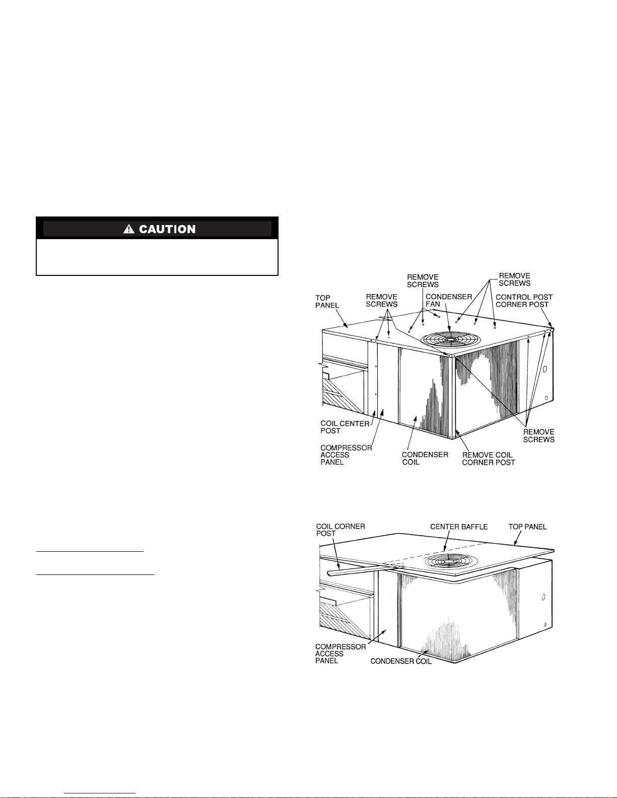
HEATING, UNITS WITH ECONOMIZER — When the
thermostat calls for heating, terminal W1 is energized. To prevent thermostat short-cycling, the unit is locked into the Heating mode for at least 1 minute when W1 is energized. The
induced-draft motor is energized and the burner ignition sequence begins. The indoor (evaporator) fan motor (IFM) is energized 45 seconds after a flame is ignited and the damper
moves to the minimum position. On units equipped for two
stages of heat, when additional heat is needed, W2 energized
and the high-fire solenoid on the main gas valve (MGV) is energized. When the thermostat is satisfie d and W1 is deenergized, the IFM stops after a 45-second time-off delay. The
economizer damper then moves to the fully closed position.
When using continuous fan, the damper will remain in the minimum position.
SERVICE
When servicing unit, shut off all electrical power to unit
and install lockout tag to avoid shock hazard or injury from
rotating parts.
6. Use a water hose or other suitable equipment to flush
down between the 2 coil sections to remove dirt and
debris. Clean the outer surfaces with a stiff brush in the
normal manner.
7. Secure inner and outer coil rows together with a fieldsupplied fastener.
8. Reposition the outer coil section and remove the coil corner post from between the top panel and center post. Reinstall the coil corner post and replace all screws.
CONDENSATE DRAIN — Check and clean each year at
start of cooling season. In winter, keep drain dry or protect
against freeze-up.
FILTERS — Clean or replace at start of each heating and cooling season, or more often if operating conditions require it. Replacement filters must be same dimensions as original filters.
OUTDOOR-AIR INLET SCREEN — Clean screen with
steam or hot water and a mild detergent. Do not use disposable
filters in place of screen.
BELTS — Check belt tension at least once each heating or
cooling season or as conditions require.
Cleaning —
Inspect unit interior at the beginning of
heating and cooling season and as operating conditions
require.
EVAPORATOR COIL
1. Turn unit power off and install lockout tag. Remove
evaporator coil access panel.
2. If economizer or two-position damper is installed, remove economizer by disconnecting Molex plug and removing mounting screws. Refer to accessory economizer
installation instructions or Optional Economizer sections
on pages 12 and 14 for more details.
3. Slide filters out of unit.
4. Clean coil using a commercial coil cleaner or dishwasher
detergent in a pressurized spray canister. Wash both sides
of coil and flush with clean water. For best results, backflush toward return-air section t o remove forei gn material. Flush condensate pan after completion.
5. Reinstall economizer and filters.
6. Reconnect wiring.
7. Replace access panels.
CONDENSER COIL — Inspect coil monthly. Clean condenser coil annually, and as required by location and outdoor
air conditions.
One-Row Coils (Size 004)
— Wash coil with commercial
coil cleaner. It is not necessary to remove top panel.
2-Row Coils (Sizes 005-007)
Clean coil as follows:
1. T urn of f unit power and install lockout tag.
2. Remove top panel screws on condenser end of unit.
3. Remove condenser coil corner post. See Fig. 42. To hold
top panel open, place coil corner post between top panel
and center post. See Fig. 43.
4. Remove screws securing coil to compressor plate and
compressor access panel.
5. Remove fastener holding coil sections together at return
end of condenser coil. Carefully separate the outer coil
section 3 to 4 in. from the inner coil section. See Fig. 44.
Fig. 42 — Cleaning Condenser Coil
Fig. 43 — Propping Up Top Panel
38
Page 39
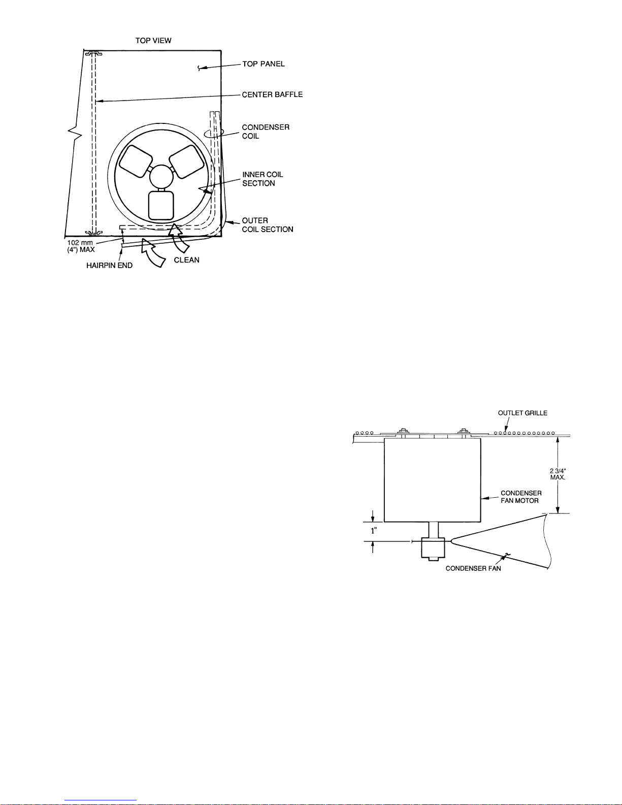
Fig. 44 — Separating Coil Sections
Fig. 45 — Condenser-Fan Adjustment
Lubrication
COMPRESSORS — Each compressor is charged with the
correct amount of oil at the factory.
FAN MOTOR BEAR INGS — Fan motor bearings are of the
permanently lubricated type. No further lubrication is required.
No lubrication of condenser or evaporator fan motors is
required.
Manual Outdoor-Air Damper —
blade adjustment is required, see Manual Outdoor-Air Damper
section on page 11.
Economizer Adjustment —
mizer sections on page 12 and 14.
Condenser-Fan Adjustment (Fig. 45) —
unit power supply. Remove condenser-fan assembly (grille,
motor, and fan) and loosen fan hub setscrews. Adjust fan
height as shown in Fig. 45. Tighten setscrews and replace
condenser-fan assembly.
Refrigerant Charge —
listed on unit nameplate (also refer to Table 1). Refer to Carrier
GTAC2-5 Charging, Recovery, Recycling, and Reclamation
training manual and the following procedures.
Unit panels must be in place when unit is operating during
charging procedure.
Amount of refrigerant charge is
If outdoor-air damper
Refer to Optional Econo-
Shut off
NO CHARG E — Use standard evacuating te chniques. After
evacuating system, weigh in the specified amount of refrigerant. (Refer to Table 1.)
LOW-CHARGE COOLING — Using Cooling Charging
Charts, Fig. 46-49, vary refrigerant until the conditions of the
appropriate chart are met. Note the charging charts are different
from type normally used. Charts are based on charging the
units to the correct superheat for the various operating conditions. Accurate pressure gage and temperature sensing device
are required. Connect the pressure gage to the service port on
the suction line. Mount the temperature sensing device on the
suction line and insulate it so that outdoor ambient temperature
does not affect the reading. Indoor-air cfm must be within the
normal operating range of the unit.
TO USE COOLING CHARGING CHART — Take the outdoor ambient temperature and read the suction pressure gage.
Refer to chart to determine what suction temperature should
be. If suction temperature is high, add refrigerant. If suction
temperature is low, carefully recover some of the charge.
Recheck the suction pressure as charge is adjusted.
EXAMPLE: (Fig. 48)
Outdoor T emperature. . . . . . . . . . . . . . . . . . . . . . . . . . . . . . 85 F
Suction Pressure . . . . . . . . . . . . . . . . . . . . . . . . . . . . . . . 80 psig
Suction T emperature should be . . . . . . . . . . . . . . . . . . . . . 76 F
(Suction Temperature may vary 5 F.)
Flue Gas Passageways —
tor box and upper areas of the heat exchanger:
1. Remove the combustion blower wheel and motor assembly according to directions in Combustion-Air Blower
section on page 42.
2. Remove the flue cover to inspect the heat exchanger.
3. Clean all surfaces as required using a wire brush.
To inspect the flue colle c-
39
Page 40
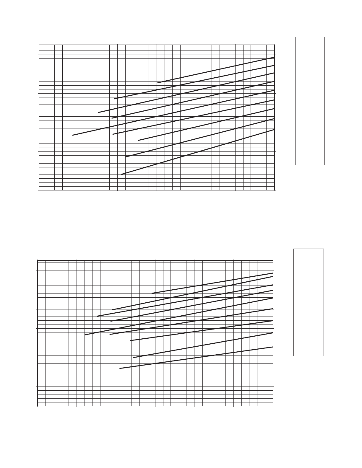
3 TON UNIT CHARGING CHART
SUCTION LINE TEMPERATURE (DEG. C)
-7 -1 4 10162127
100
90
80
70
689
621
552
483
OUTDOOR
TEMP
F C
125 52
115 46
105 41
95 35
85 29
75 24
65 18
55 13
45 7
60
50
SUCTION LINE PRESSURE (PSIG)
40
30
20 30 40 50 60 70 80
SUCTION LINE TEMPERATURE (DEG. F)
414
345
SUCTION LINE PRESSURE (KILOPASCALS)
276
207
Fig. 46 — Cooling Charging Chart, 48TF004
4 TON UNIT CHARGING CHART
SUCTION LINE TEMPERATURE (DEG. C)
-7 -1 4 10162127
100
90
689
621
OUTDOOR
TEMP
F C
125
115
52
46
105 41
95 35
85 29
80
70
60
50
SUCTION LINE PRESSURE (PSIG)
40
30
20 30 40 50 60 70 80
SUCTION LINE TEMPERATURE (DEG. F)
Fig. 47 — Cooling Charging Chart, 48TF005
40
552
483
414
345
276
207
75
65
55
45 7
SUCTION LINE PRESSURE (KILOPASCALS)
24
18
13
Page 41
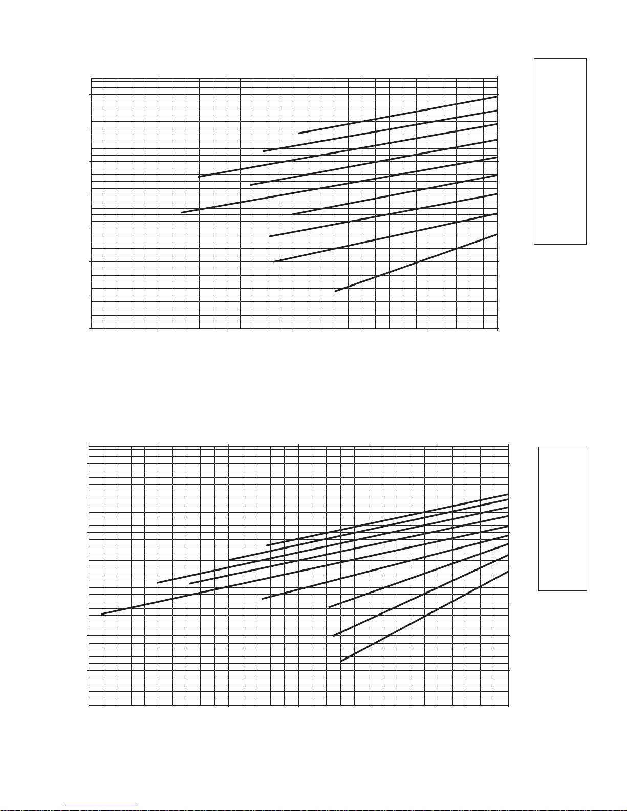
5 TON UNIT CHARGING CHART
SUCTION LINE TEMPERATURE (DEG. C)
-7 -1 4 10 16 21 27
100
90
80
70
689
621
552
483
OUTDOOR
TEMP
F C
125 52
115 46
105 41
95 35
85 29
75 24
65 18
55 13
45 7
60
50
SUCTION LINE PRESSURE (PSIG)
40
30
20 30 40 50 60 70 80
SUCTION LINE TEMPERATURE (DEG. F)
Fig. 48 — Cooling Charging Chart, 48TF006
6 TON UNIT (60 Hz) CHARGING CHART
SUCTION LINE TEMPERATURE (DEG. C)
-7 -1 4 10 16 21 27
100
90
80
70
414
345
276
207
SUCTION LINE PRESSURE (KILOPASCALS)
689
621
552
483
OUTDOOR
TEMP
F C
125 52
115 46
105 41
95 35
85 29
75 24
65 18
55 13
45 7
60
50
SUCTION LINE PRESSURE (PSIG)
40
30
20 30 40 50 60 70 80
414
345
SUCTION LINE PRESSURE (KILOPASCALS)
276
207
SUCTION LINE TEMPERATURE (DEG. F)
Fig. 49 — Cooling Charging Chart, 48TF007
41
Page 42
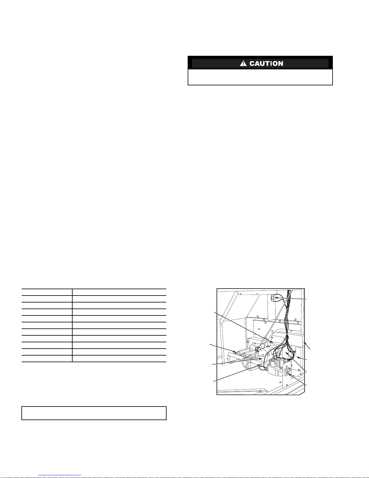
Combustion-Air Blower —
Fig. 50 — Burner Section Details
Clean periodically to
assure proper airflow and heating efficiency. Inspect blower
wheel every fall and periodically during heating season. For the
first heating season, inspect blower wheel bimonthly to determine proper cleaning frequency.
To access burner section, slide the sliding burner partition
out of the unit.
To inspect blower wheel, shine a flashlight into draft hood
opening. If cleaning is required, remove motor and wheel as
follows:
1. Slide burner access panel out.
2. Remove the 7 screws that attach induced-draft motor
housing to vestibule plate (Fig. 50).
3. The blower wheel can be cleaned at this point. If additional cleaning is required, continue with Steps 4 and 5.
4. To remove blower from the motor shaft, remove 2
setscrews.
5. To remove motor, remove the 4 screws that hold the motor to mounting plate. Remove the motor cooling fan by
removing one setscrew. Then remove nuts that hold motor to mounting plate.
6. To reinstall, reverse the procedure outlined above.
Limit Switch —
Remove blower access panel (Fig. 7).
Limit switch is located on the fan deck.
Burner Ignition —
Unit is equipped with a direct spark
ignition 100% lockout system. Integrated Gas Unit Controller
(IGC) is located in the control box (Fig. 11). The IGC contains
a self-diagnostic LED (light-emitting diode). A single LED on
the IGC provides a visual display of operational or sequential
problems when the power supply is uninterrupted. When a
break in power occurs, the IGC will be reset (resulting in a loss
of fault history) and the indoor (evaporator) fan ON/OFF times
will be reset. The LED error code can be observed through the
viewport. During servicing refer to the label on the control
box cover or Table 31 for an explanation of LED error code
descriptions.
If lockout occurs, unit may be reset by interrupting power
supply to unit for at least 5 seconds.
Table 31 — LED Error Code Description
Main Burners —
To access burners, remove burner access panel and slide out burner partition. At the beginning of
each heating season, inspect for deterioration or blockage due
to corrosion or other causes. Observe the main burner flames
and adjust, if necessary.
When working on gas train, do not hit or plug orifice
spuds.
REMOVAL AND REPLACEMENT OF GAS TRAIN
(Fig. 50-52)
1. Shut off manual gas valve.
2. Shut off power to unit .
3. Slide out burner parti tion.
4. Disconnect gas piping at unit gas valve.
5. Remove wires connected to gas valve. Mark each wire.
6. Remove ignitor wires and sensor wires at the Integrated
Gas Unit Controller (IGC) (see Fig. 11).
7. Remove the 2 screws that attach the burner rack to the
vestibule plate (Fig. 50).
8. Slide the burner tray out of the unit (Fig. 51).
9. To reinstall, reverse the procedure outlined above.
CLEANING AND ADJUSTMENT
1. Remove burner rack from unit as described in Removal
and Replacement of Gas Train section, above.
2. Inspect burners; if dirty, remove burners from rack.
3. Using a soft brush clean burners and cross-over port as
required.
4. Adjust spark gap. See Fig. 52.
5. Reinstall burners on rack.
6. Reinstall burner rack as described in Removal and Replacement of Gas Train section, above.
Replacement Parts —
A complete list of replacement
parts may be obtained from any Carrier distributor upon
request.
LED INDICATION ERROR CODE DESCRIPTION
ON
OFF
1 Flash†
2 Flashes
3 Flashes
4 Flashes
5 Flashes
6 Flashes
7 Flashes
8 Flashes
LEGEND
Light-Emitting Diode
LED —
*A 3-second pause exists between LED error code flashes. If more
than one error code exists, all applicable codes will be displayed in
numerical sequence.
†Indicates a code that is not an error. The unit will continue to oper-
ate when this code is displayed.
IMPORTANT: Refer to Troubleshooting Tables 32-36 for additional information.
Normal Operation
Hardware Failure
Evaporator F an On/Off Delay Modified
Limit Switch Fault
Flame Sense Fault
4 Consecutive Limit Switch Faults
Ignition Lockout Fault
Induced-Draft Motor Fault
Rollout Switch Fault
Internal Control Fault
42
INDUCEDDRAFT
MOTOR
MOUNTING
PLATE
BURNER
SECTION
INDUCEDDRAFT
MOTOR
MANIFOLD
PRESSURE
TAP
ROLLOUT
SWITCH
FLUE
EXHAUST
VESTIBULE
PLATE
BLOWER
HOUSING
GAS
VALV E
Page 43
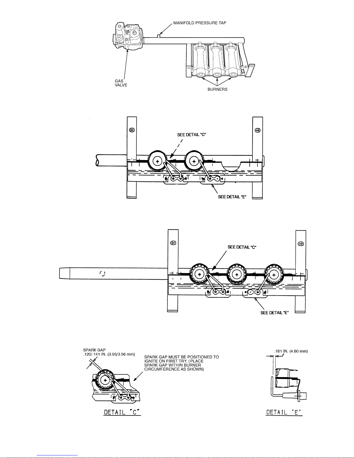
Fig. 51 — Burner Tray Details
48TFE004, 48TFD005-007 — 74,000 BTUH INPUT
48TFM004, 48TFL005-006 — 60,000 BTUH INPUT
48TFE005-007, 48TFF004 — 115,000 BTUH INPUT
48TFF005-007 — 150,000 BTUH INPUT
48TFN004, 48TFM005-006 — 90,000 BTUH INPUT
48TFN005-006 — 120,000 BTUH INPUT
LOW HEAT
MEDIUM AND HIGH HEAT
Fig. 52 — Spark Adjustment
43
Page 44
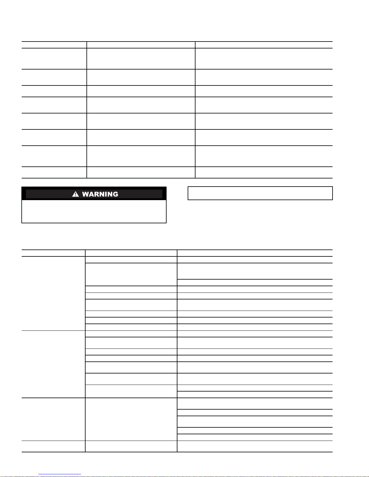
TROUBLESHOOTING
Table 32 — LED Error Code Service Analysis
PROBLEM CAUSE REMEDY
Hardware failure.
(LED OFF)
Limit switch fault.
(LED 2 flashes)
Flame sense fault.
(LED 3 flashes)
4 consecutive limit
switch trips.
(LED 4 flashes)
Ignition lockout.
(LED 5 flashes)
Induced-draft motor fault.
(LED 6 flashes)
Rollout switch fault.
(LED 7 flashes)
Internal control fault.
(LED 8 flashes)
If the IGC must be replaced, be sure to ground yourself to dissipate any electrical charge that may be present before handling
new control board. The IGC is sensitive to static electricity and
may be damaged if the necessary precautions are not taken.
Loss of power to control module (IGC). Check 5 amp fuse on IGC, power to unit, 24-v circuit breaker,
High temperature limit switch is open. Check the operation of the indoor (evaporator) fan motor.
The IGC sensed flame that should not be
present.
Inadequate airflow to unit. Check operation of indoor (evaporator) fan motor and that
Unit unsuccessfully attempted ignition for
15 minutes.
IGC does not sense that induced-draft motor is
operating.
Rollout switch has opened. Rollout switch will automatically reset, but IGC will continue to
Microprocessor has sensed an error in the software or hardware.
and transformer. Units without a 24-v circuit breaker have an
internal overload in the 24-v transformer. If the overload trips,
allow 10 minutes for automatic reset.
Ensure that the supply-air temperature rise is in accordance
with the range on the unit nameplate.
Reset unit. If problem persists, replace control board.
supply-air temperature rise agrees with range on unit nameplate information.
Check ignitor and flame sensor electrode spacing, gaps, etc.
Ensure that flame sense and ignition wires are properly terminated. Verify that unit is obtaining proper amount of gas.
Check for proper voltage. If motor is operating, check the
speed sensor plug/IGC Terminal J2 connection. Proper connection: PIN 1 — White, PIN 2 — Red, PIN 3 — Black.
lock out unit. Check gas valve operation. Ensure that induced
draft blower wheel is properly secured to motor shaft. Reset
unit at unit disconnect.
If error code is not cleared by resetting unit power, replace the
IGC.
IMPORTANT: Refer to Table 19 — Heating Service Analysis
for additional troubleshooting analysis.
LEGEND
IGC —
LED —
Integrated Gas Unit Controller
Light-Emitting Diode
PROBLEM CAUSE REMEDY
Burners will not ignite.
Inadequate heating.
Poor flame characteristics.
Burners will not turn off.
Table 33 — Heating Service Analysis
Misaligned spark electrodes. Check flame ignition and sensor electrode positioning. Adjust as needed.
No gas at main burners. Check gas line for air, purge as necessary. After purging gas line of air,
Water in gas line. Drain water and install drip leg to trap water.
No power to furnace. Check power supply, fuses, wiring, and circuit breaker.
No 24 v power supply to control circuit. Check transformer. Transformers with internal overcurrent protection
Miswired or loose connections. Check all wiring and wire nut connections.
Burned-out heat anticipator in thermostat. Replace thermostat.
Broken thermostat wires. Run continuity check. Replace wires, if necessary.
Dirty air filter. Clean or replace filter as necessary.
Gas input to unit too low. Check gas pressure at manifold. Clock gas meter for input. If too low,
Unit undersized for application. Replace with proper unit or add additional unit.
Restricted airflow. Clean filter, replace filter, or remove any restrictions.
Blower speed too low. Use high speed tap, increase fan speed, or install optional blower, as
Limit switch cycles main burners. Check rotation of blower, thermostat heat anticipator settings, and temToo much outdoor air. Adjust minimum position.
Incomplete combustion (lack of combustion air) results in:
Aldehyde odors, CO, sooting flame, or
floating flame.
Unit is locked into Heating mode f or a one
minute minimum.
allow gas to dissipate for at least 5 minutes before attempting to relight
unit.
Check gas valve.
require a cool down period before resetting.
increase manifold pressure, or replace with correct orifices.
suitable for individual units.
perature rise of unit. Adjust as needed.
Check economizer operation.
Check all screws around flue outlets and burner compartment. Tighten
as necessary.
Cracked heat exchanger.
Overfired unit — reduce input, change orifices, or adjust gas line or man-
ifold pressure.
Check vent for restriction. Clean as necessary.
Check orifice to burner alignment.
Wait until mandatory one minute time period has elapsed or re-
set power to unit.
44
Page 45
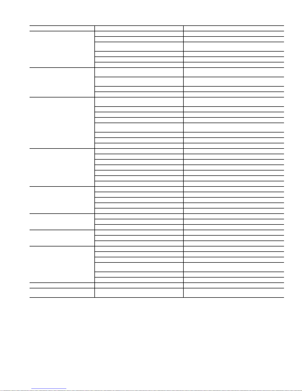
PROBLEM CAUSE REMEDY
Compressor and condenser fan
will not start.
Compressor will not start but
condenser fan runs.
Compressor cycles (other than
normally satisfying thermostat).
Compressor operates
continuously.
Excessive head pressure.
Head pressure too low.
Excessive suction pressure.
Suction pressure too low.
Evaporator fan will not shut off.
Compressor makes excessive
noise (48TF007 scroll only).
Table 34 — Cooling Service Analysis
Power failure. Call power company.
Fuse blown or circuit breaker tripped. Replace fuse or reset circuit breaker.
Defective thermostat, contactor, transformer, or
control relay.
Insufficient line voltage. Determine cause and correct.
Incorrect or faulty wiring. Check wiring diagram and rewire correctly.
Thermostat setting too high. Lower thermostat setting below room temperature.
Faulty wiring or loose connections in compressor
circuit.
Compressor motor burned out, seized, or internal
overload open.
Defective run/start capacitor , overload, start relay. Determine cause and replace.
One leg of three-phase power dead. Replace fuse or reset circuit breaker. Determine cause.
Refrigerant overcharge or undercharge. Recover refrigerant, evacuate system, and recharge to
Defective compressor. Replace and determine cause.
Insufficient line voltage. Determine cause and correct.
Blocked condenser. Determine cause and correct.
Defective run/start capacitor, overload, or start
relay.
Defective thermostat. Replace thermostat.
Faulty condenser-fan motor or capacitor. Replace.
Restriction in refrigerant system. Locate restriction and remove.
Dirty air filter. Replace filter.
Unit undersized for load. Decrease load or increase unit size.
Thermostat set too low. Reset thermostat.
Low refrigerant charge. Locate leak; repair and recharge.
Leaking valves in compressor. Replace compressor.
Air in system. Recover refrigerant, evacuate system, and recharge.
Condenser coil dirty or restricted. Clean coil or remove restriction.
Dirty air filter. Replace filter.
Dirty condenser coil. Clean coil.
Refrigerant overcharged. Recover excess refrigerant.
Air in system. Recover refrigerant, evacuate system, and recharge.
Condenser air restricted or air short-cycling. Determine cause and correct.
Low refrigerant charge. Check for leaks; repair and recharge.
Compressor valves leaking. Replace compressor.
Restriction in liquid tube. Remove restriction.
High head load. Check for source and eliminate.
Compressor valves leaking. Replace compressor.
Refrigerant overcharged. Recover excess refrigerant.
Dirty air filter. Replace filter.
Low refrigerant charge. Check for leaks; repair and recharge.
Metering device or low side restricted. Remove source of restriction.
Insufficient evaporator airflo w. Increase air quantity. Check filter and replace if
Temperature too low in conditioned area. Reset thermostat.
Outdoor ambient below 25 F. Install low-ambient kit.
Time off delay not finished. Wait for 30-second off delay.
Compressor rotating in wrong direction. Reverse the 3-phase power leads as described in the
Replace component.
Check wiring and repair or replace.
Determine cause. Replace compressor.
nameplate.
Determine cause and replace.
necessary.
Start-Up section on page 36.
45
Page 46
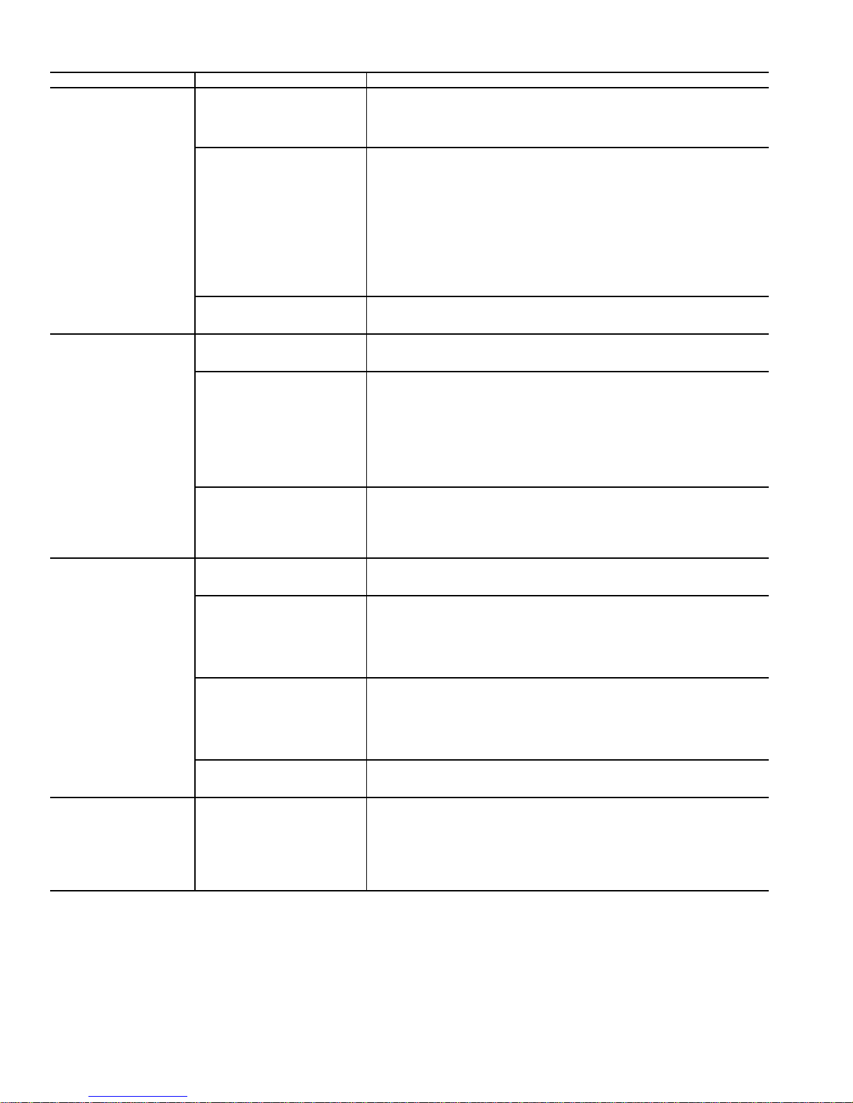
PROBLEM CAUSE REMEDY
Damper does not open.
Economizer operation
limited to minimum
position.
Damper does not close.
Economizer damper does
not close on power loss.
LEGEND
C1 —
EC —
IFC —
IFO —
OAT —
PL —
SAT —
SW —
Common Power
Enthalpy Control
Indoor (Evaporator) Fan Contactor
Indoor (Evaporator) Fan On
Outdoor-Air Thermostat
Plug
Supply-Air Thermostat
Economizer Position Switch
Table 35 — Durablade Economizer Troubleshooting
Indoor (evaporator) fan is off. 1. Check to ensure that 24 vac is present at terminal C1 on the IFC or that
No power to economizer motor. 1. Check that SW3 is properly making contact with the damper blade. Check
Economizer motor failure. If the indoor (evaporator) fan and economizer motor are energized, verify that
OAT or EC set too high. 1. Set at correct temperature (3 F below indoor space temperature).
Verify economizer control board
is correctly wired and works
properly.
Check SAT. 1. After verifying that the OAT and EC settings and the economizer control
Incorrect wiring of economizer. 1. Verify that SW2 and SW4 are wired and working properly (see unit label
Verify economizer control board
is functioning properly.
Check SAT. 1. After verifying that the wiring is correct and the economizer control board is
Economizer motor failure. If economizer control board and SAT are functioning properly, verify that there is
Verify that close-on-power-loss
and economizer control board
are functioning properly.
24 vac is present at the IFO terminal. Check whether 24 vac is present at
PL6-1 (red wire) and/or PL6-3 (black wire). If 24 vac is not present, check wiring (see unit label diagram).
2. Check proper thermostat connection to G on the connection board.
that SW1 is in the NC (normally closed) position.
2. Check diode D18. If diode is not functioning properly, replace D18.
3. Confirm that the economizer control board is grounded properly at PL6-4
(brown wire) and at brown terminal of the economizer control board (brown
wire). The economizer motor must also be grounded properly at the negative
motor terminal (brown wire).
4. Verify SW1 and SW3 are working and wired properly (see unit label diagram).
5. Check for 24 vac input at both PL6-1 (red wire) and PL6-3 (black wire). If
24 vac not present, check unit wiring (see unit label diagram). If 24 vac is
found in both places, check for 24 vac at the yellow terminal of the economizer control board (yellow wire). If 24 vac power is not present, replace the
economizer control board.
there is a minimum of 18 vdc at the positive motor terminal. If the motor is not
operating, replace the motor.
2. Check OAT or EC by setting above outdoor temperature or humidity level. If
the OAT or EC switches do not close, replace OAT or EC.
1. Perform the following tests when OAT or EC is closed, Y1 is called for and
damper is at minimum position. Confirm 24 vac on gray terminal of the economizer control board (gray wire). If 24 vac is not present, check wiring (see
unit label diagram).
2. Verify that SW1 and SW3 are wired correctly and working properly (see unit
label diagram).
3. Check to ensure that 24 vac exists at PL6-2 (blue wire). If 24 vac is not
present, check wiring (see unit wiring label diagram).
4. Check 24 vac output at PL6-10 (white wire). If 24 vac is not present, replace
economizer control board.
board wiring are correct, check to ensure that the 24 vac terminal of the SAT
has 24 vac (white wire). If OAT, EC, and control board are functioning and
wired properly and no 24 vac exists, check wiring (see unit label diagram).
2. If supply-air temperature is greater than 57 F, 24 vac should be found at
terminal T2 on the SAT (pink wire). If 24 vac is not present, replace SAT.
diagram.).
2. Check diode D19. If diode is not functioning properly, replace D19.
1. After verifying that the wiring is correct, modulate the damper to the minimum
position. Remove the calls for G.
2. If the damper does not move, check for 24 vac at PL6-1 (red wire). If 24 vac is
not present, check wiring (see unit label diagram).
3. If damper still does not move, check for 24 vac at blue terminal of economizer
control board (blue wire). If 24 vac is not present, replace the economizer circuit board.
functioning properly , place the OAT or EC switch in the closed position. Place
a call for Y1 and open the damper to the fully open position. Confirm that the
24 vac terminal of the SAT has 24 vac (white wire). If 24 vac is not present,
check wiring (see unit label diagram).
2. If supply-air temperature is less than 52 F, 24 vac should be found at terminal
T1 on the SAT (violet wire). If 24 vac not found, replace SAT.
a minimum of 18 vdc at the positive motor terminal. If a minimum of 18 vdc is
present and the motor is still not operating, replace the motor.
1. Check voltage potential across batteries. If lower than 14 vdc, replace closeon-power-loss power supply (9-v alkaline batteries). It is recommended that
you check this emergency power supply on a regular basis or whenever the
filters are changed.
2. If the close-on-power-loss and economizer control board are functioning
properly , check for 14 vdc or higher at the blue terminal of the economizer
control board (blue wire) when power is disconnected from unit. If 14 vdc is
not present, replace the control board.
46
Page 47
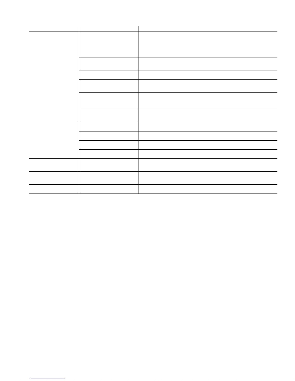
PROBLEM CAUSE REMEDY
Damper does not open.
EconoMi$er operation
limited to minimum
position.
Damper position less
than minimum position
set point.
Damper does not return
to minimum position.
Damper does not close
on power loss.
LEGEND
Outdoor-Air Tem perature
OAT —
Table 36 — EconoMi$er Troubleshooting
Indoor (evaporator) fan is Off. Check to ensure that 24 vac is present at terminal C1 (Common Power) on the
No power to EconoMi$er
controller.
No power to G terminal. If IFM is on, check to ensure 24 vac is present on G terminal of the EconoMi$er
Controller fault. If STATUS light is flashing one flash, the EconoMi$er controller is experiencing a
Thermostat fault. If STATUS light is flashing two flashes, the EconoMi$er controller senses the
Actuator fault. Check the wiring between the EconoMi$er controller and the actuator.
Minimum position set incorrectly. Verify that the MIN POS (%) is set greater than zero. Adjust MIN POS (%) to
EconoMi$er changeover set-
point set too high or too low.
Supply-Air Temperature Sensor
faulty.
OAT Sensor faulty If ST ATUS light is flashing five flashes, the OAT sensor is faulty. Chec k wiring or
Supply-Air Low Limit Strategy
controlling.
CO
Ventilat ion Str ategy
2
controlling
Damper travel is restricted. Check to ensure the damper is not blocked.
IFC (Indoor Evaporator Fan Contactor) or that 24 vac is present at the IFO
(Indoor Evaporator Fan On) terminal. Check whether 24 vac is present at PL
(Plug) 6-1 (red wire) and/or PL6-3 (black wire). If 24 vac is not present, check
wiring (see unit label diagram).
Check proper thermostat connection to G on the connection board.
Check to ensure that 24 vac is present across Terminals 24 VAC and 24V COM
on the EconoMi$er control. If 24 vac is not present, check wiring (see unit label
diagram). If 24 vac is present, STATUS light should be on constantly.
controller. If 24 vac is not present, check wiring (see unit label diagram).
fault condition. Cycle power to the controller. If condition continues, replace the
EconoMi$er controller.
thermostat is wired incorrectly. Check wiring between the thermostat and the
connection board in the electrical panel. The fault condition is caused by Y2
being energized before Y1.
Hold CONFIG button between three and ten seconds to verify the actuator’s
operation. (This process takes three minutes to complete.)
100% to verify operation, and then set to correct setting.
Set at correct value. See Table 3.
If STATUS light is flashing four flashes, the Supply-Air Temperature Sensor is
faulty. Check wiring or replace sensor.
replace sensor.
The supply-air temperature is less than 45 F, causing the minimum position to
decrease. Refer to the Start-Up instructions. Verify correc t setting of MIN POS
(%). If correct, EconoMi$er is operating correctly.
If CO2 sensor is being used, and the damper position is greater than minimum
position, the ventilation control strategy is controlling. Refer to the Start-Up
instructions. EconoMi$er is operating correctly.
47
Page 48
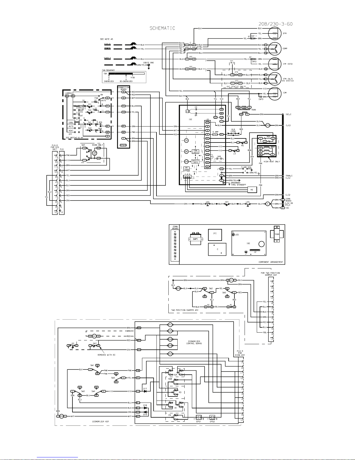
Fig. 53 — Typical Wiring Diagram and Component Arrangement
48
Page 49
LEGEND FOR FIG. 53 — TYPICAL WIRING SCHEMATIC AND COMPONENT ARRANGEMENT
IMPORTANT: Refer to unit wiring label for actual unit wiring
information.
AHA —
C—
CAP —
CC —
COMP —
D—
EC —
ECON —
EPS —
EQUIP —
ER —
FPT —
FU —
GND —
HPS —
HS —
I—
IDM —
IFC —
IFM —
IGC —
LPS —
LS —
MGV —
MTR —
OAT —
OFM —
OLR —
PL —
QT —
R—
Adjustable Heat Anticipator
Contactor, Compressor
Capacitor
Cooling Compensator
Compressor Motor
Diode
Enthalpy Control
Economizer
Emergency Power Supply
(Nine Volt Battery)
Equipment
Economizer Relay
Freeze Up Protection Thermostat
Fuse
Ground
High-Pressure Switch
Hall-Effect Sensor
Ignitor
Induced-Draft Motor
Indoor Fan Contactor
Indoor (Evaporator) Fan Motor
Integrated Gas Unit Controller
Low-Pressure/Loss-of-Charge Switch
Limit Switch
Main Gas Valve
Motor
Outdoor-Air Thermostat
Outdoor (Condenser) Fan Motor
Overload Relay
Plug Assembly
Quadruple Terminal
Relay
NOTES:
1. If any of the original wire furnished must be replaced, it must be replaced with type 90 C wire or
its equivalent.
2. Three-phase motors are protected under primary single-phasing conditions.
3. Thermostat: HH07AT170, 172, 174 and P272-2783 Subbase: HH93AZ176, 178 and
P272-1882, 1883.
4. Set heat anticipator at .14 amp. For units with 2 stages of heating, set stage two anticipator at
.14 amp.
5. Use copper conductors only.
from 230-v tap (ORN) and connect to 208-v tap (RED). Insulate end of 230-v tap.
RS —
SAT —
SEN —
SW1 —
SW2 —
SW3 —
SW4 —
TC —
TDR —
TH —
TRAN —
Rollout Switch
Supply Air Thermostat
Sensor
Switch Fully Open
Switch Fully Closed
Switch Min. Vent Position
Switch Max. Vent Position
Thermostat-Cooling
Time-Delay Relay
Thermostat-Heating
Transformer
Field Splice
Marked Wire
Terminal (Marked)
Terminal (Unmarked)
Terminal Block
Splice
Splice (Marked)
Factory Wiring
Field Control Wiring
Field Power Wiring
Accessory or Optional Wiring
To indicate common potential only;
not to represent wiring.
49
Page 50

Copyright 2000 Carrier Corporation
Manufacturer reserves the right to discontinue, or change at any time, specifications or designs without notice and without incurring obligations.
Book 1 4
Tab 1a 6a
PC 111 Catalog No. 534-80000 Printed in U.S.A. Form 48TF-1SI Pg 50 8-00 Replaces: New
Page 51

Page 52
START-UP CHECKLIST
(Remove and Use in Job File)
I. PRELIMINARY INFORMATION:
MODEL NO.: _________________________________ SERIAL NO.: ______________________________________
DATE: _______________________________________ TECHNICIAN: ____________________________________
BUILDING LOCATION: _____________________________
II. PRE-START-UP (insert checkmark in box as each item is completed)
VERIFY THA T ALL PACKING MATERIALS HAVE BEEN REMOVED FROM UNIT
REMOVE ALL SHIPPING HOLDDOWN BOLTS AND BRACKETS PER INSTALLATION INSTRUCTIONS
VERIFY THA T CONDENSATE CONNECTION IS INST ALLED PER INSTALLATION INSTRUCTIONS
VERIFY THA T FLUE HOOD IS INSTALLED
CHECK ALL ELECTRICAL CONNECTIONS AND TERMINALS FOR TIGHTNESS
CHECK TO ENSURE NO WIRES ARE TOUCHING REFRIGERANT TUBING OR SHARP EDGES
CHECK GAS PIPING FOR LEAKS
CHECK THAT INDOOR-AIR FILTER IS CLEAN AND IN PLACE
VERIFY THA T UNIT INSTALLATION IS LEVEL
CHECK FAN WHEEL AND PROPELLER FOR LOCATION IN HOUSING/ORIFICE AND SETSCREW TIGHTNESS
VERIFY PULLEY ALIGNMENT AND BEL T TENSION ARE CORRECT
III. START-UP:
ELECTRICAL
SUPPLY VOLTAGE L1-L2 _________ L2-L3 __________ L3-L1 __________
COMPRESSOR AMPS L1 _________ L2 __________ L3 __________
INDOOR-FAN AMP L1 _________ L2 __________ L3 __________
TEMPERATURES
OUTDOOR-AIR TEMPERA TURE __________ DB _________ WB
RETURN-AIR TEMPERATURE __________ DB _________ WB
COOLING SUPPLY AIR __________ DB _________ WB
GAS HEAT SUPPLY AIR __________ DB
PRESSURES
GAS INLET PRESSURE __________ IN. WG
GAS MANIFOLD PRESSURE __________ IN. WG (LOW FIRE) ________ IN. WG (HI FIRE)
REFRIGERANT SUCTION __________ PSIG ________ TEMP ° F
REFRIGERANT DISCHARGE __________ PSIG ________ TEMP ° F
VERIFY REFRIGERANT CHARGE USING CHARGING TABLES
VERIFY THAT 3-PHASE SCROLL COMPRESSOR IS ROTATING IN CORRECT DIRECTION (48TF007 ONLY)
CUT ALONG DOTTED LINE CUT ALONG DOTTED LINE
Copyright 2000 Carrier Corporation
Manufacturer reserves the right to discontinue, or change at any time, specifications or designs without notice and without incurring obligations.
Book 1 4
Tab 1a 6 a
PC 111 Catalog No. 534-80000 Printed in U.S.A. Form 48TF-1SI Pg CL-1 8-00 Replaces: New
- - - - - - - - - - - - - - - - - - - - - - - - - - - - - - - - - - - - - - - - - - - - - - - - - - - - - - - - - - - - - - - - - - - - - - - - - - - - - - - - - - - - - - - - - - - - - - - - - - - - - - - - - - - - - - - - - - - - - - - - - - - - - - - - - - - - - - - - - - - - - - - - - - - - - - - - - - - - - - - - - - - - - - - - - - - - -- - - - - - - - - - - - - - - - - - - -
 Loading...