

Page 1
48KHA,KLA
Packaged Heating/Cooling Units
Installation, Start-Up and Service Instructions
NOTE TO INSTALLER: After installation, leave these instructions, Owner’s Manual and Peurts Replace
ment Guide with equipment owner.
CONTENTS
Page
SAFETY CONSIDERATIONS
GENERAL..........................................................................1,2
INSTALLATION
Step 1—Rig and Place Unit..............................................2-4
.................................................................
...............................................
1
2-8
• ROOFTOP INSTALLATION
• GROUND LEVEL INSTALLATION
• CLEARANCES
• CONDENSATE DISPOSAL
• VENTING
Step 2—Make Gas Piping Connections
Step 3—Make Duct Connections........................................6
Step 4—Make Wiring Connections
..........................
.................................
5,6
6,7
• HIGH-VOLTAGE CONNECTIONS
• SPECIAL PROCEDURES FOR
208-V OPERATION
• LOW-VOLTAGE CONNECTIONS
• HEAT ANTICIPATOR SETTING
START-UP........................................................................9-16
SERVICE........................................................................16-19
TROUBLESHOOTING CHARTS
SAFETY CONSIDERATIONS
...................................
20,21
A WARNING
Improper installation, adjustment, eJteration, service,
maintenance or use can cause carbon monoxide poison
ing, explosion, fire, electric shock or other occurrences
which may injure you or damage your property. Con
sult a qualified instedler, service agency or the gas sup
plier for information or assistance.
NOTE: Installation of this unit must conform to the guide
lines presented in these Installation Instructions. Read and
become familiar with this publication before starting
installation.
Only trained, qualified installers and service mechanics
should install, start-up and service this equipment. Consult
the User’s Manual for routine maintenance. All other opera
tions should be performed by tredned service personnel,
personnel.
• Follow all safety codes.
• Wear safety glasses and work gloves.
• Use care in handling, rigging and setting bulky equip
ment.
• Observe precautions in these instructions and on equip
ment tags, stickers and labels.
* •
A WARNING
Do not disconnect electric power to this appliance with
out first turning off gas supply. Be sure power to equip
ment is shut off before meuntenance or service.
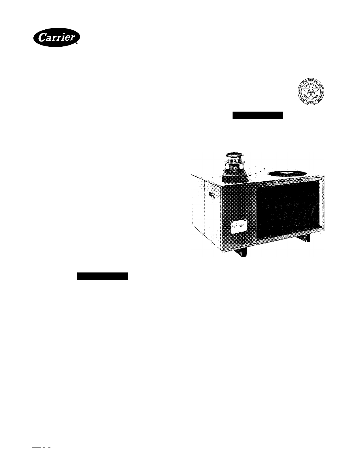
Fig. 1—Model 48KHA,KLA
GENERAL
Models 48KHA,KLA packaged gas/electric units (Fig. 1) eire
design certified in accordance with ANSI Z21.47B-1986,
ARI Standeird 210-81 and ARI Stemdard 270-84. The units
are design certified by the American Gas Association
(AGA) for use with natural or propane gases with appropri
ate controls or orifices. See Table 1 for heating input rat
ings. Models 48KHA,KLA units are fully self-contedned,
combination gas-heating/electric-cooling units designed for
outdoor installation on either a rooftop or ground-level slab.
May be instedled directly on wood flooring or on Class A,
Class B or Class C roof covering materials.
These units are equipped with an energy-saving automatic,
intermittent, electric spark ignition system that does not
have a continuously burning pilot. All units are manufac
tured with natural gas controls.
Units with number 1 in the 4th digit location of model num
ber in Table 1 meet California oxides of nitrogen (NOx) max
imum emission requirements.
Units are factory charged with R-22 refrigerant. To install:
connect gas supply, air ducts, high- and low-voltage wiring
and condensate drain, and install a field-supplied air filter in
the return-air ductwork.
Manufacturer reserves the right to discontinue, or change at any time, specifications or designs without notice and without incurring obiigations.
BookI 1 I 4 PC 101 Cataiog No 534-862 Printed in USA Form 48KH,KL-19Si Pg 1 1-88 Replaces: 48KH,KL-17SI
Tab ila 11a For replacement items contact distributor.
Page 2
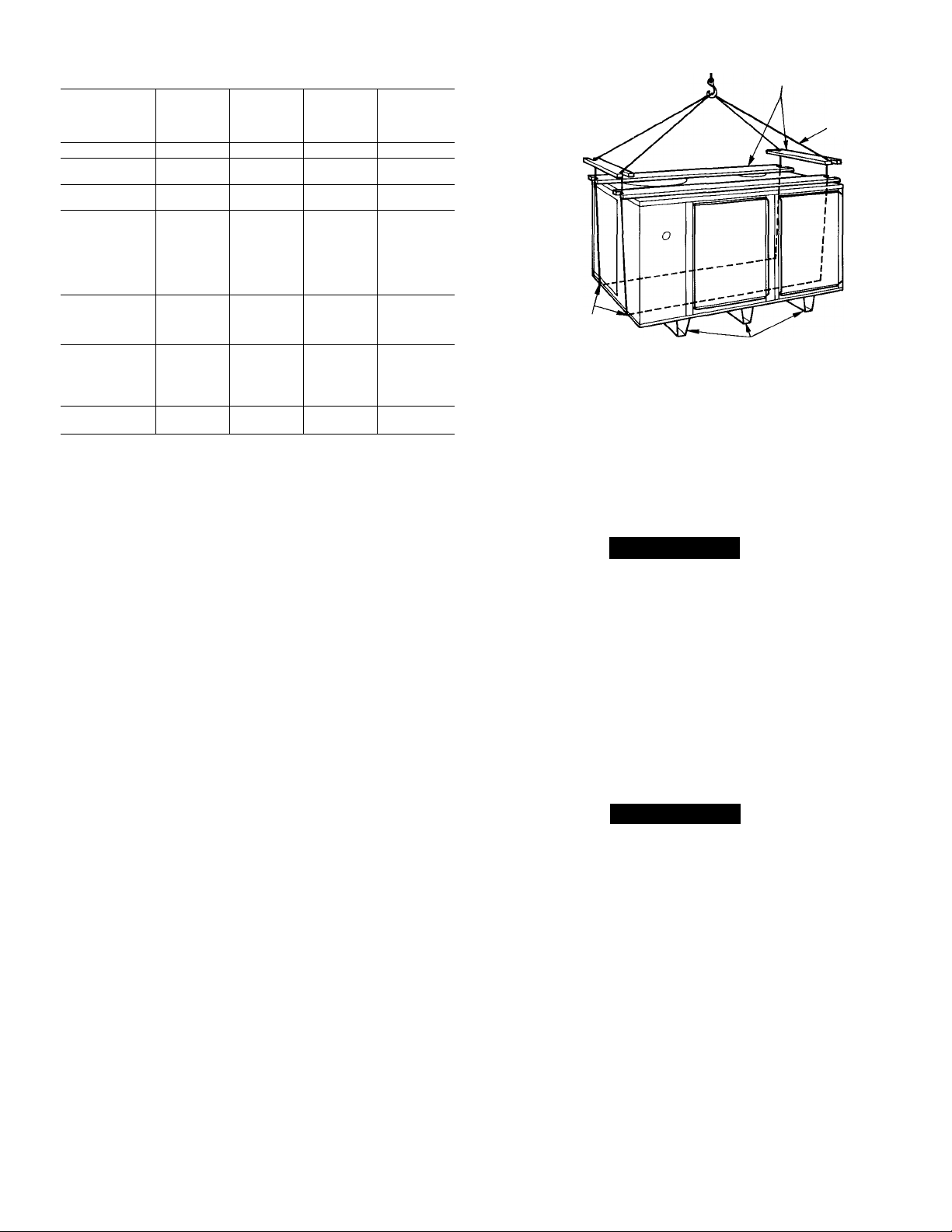
Table 1—Performance Data
COOLING
MODEL 48-
KLA118310BE
KLA124310BE
KHA024310BF
KLA130310BE
KHA030310BF
KLA136310BE
KLA136510CE
KLA136610CE
KHA136310BE
KHA136S10CE
KHA036310BF
KHA036510CF
KLA142310BE
KLA142510CE
KHA042310BF
KHA042510CF
KLA148310BE
KLA148510CE
KLA148610CE
KHA048310BE
KHA048510CF
KLA160310BE
KHA060310BF
♦Rated in accordance with U S. Government D.O.E. test procedures and/
or ARI Standard 210-81.
tSound rating per ARi 270-84.
tThe capacity ratings of singie-phase units are in accordance with U.S.
Government D.O.E. test procedures and/or AGA certification require
ments. For 3-phase units, the efficiency rating is a product thermai effi
ciency rating determined under continuous operating conditions, inde
pendent of any installed system.
CAPACITY
(Btuh)*
17,800 40,000 32,000
23,800 40,000
24,000 75,000
29,600
29,600 75,000 58,000
36,000 60,000
36,000
36,000 60,000
36,000
36,000
36,000
36,000
42,000 60,000
42,000 60,000
42,000
42,000 125,000
49,000
49,000
49,000
49,000
49,000
60,000
60,000
RATED
HEATING
INPUT
(Btuh)
40,000 32,000
60,000
100,000 79,000
100,000 75,000
125,000
125,000
125,000 97,000
80,000 63,000
80,000 60,000
80,000 60,000
125,000 97,000
125,000 93,750 8.4*
100,000* 79,000* 8.4*
150,000* 116,000* 8.4*
OUTPUT
CAPACITY
(Btuh)
32,000
58,000
47,000
45,000
45,000
97,000
93,750
47,000
45,000
93,750
ARI*
SOUND
RATING
(Bels)
7.8
7.8
8.0
7.8
7.8
8.0
8.0
8.0
8.0
8.0
8.0
8.0
78
7.8
7.8
7.8
8.4*
8.4*
8.4*
8.4*
SPREADER OARS' ^
(2)2x4xUNIT LENGTH PLUS 10"WITH
11 DEEP 90° NOTCHES EACH END
(2) 2x4xUNIT WIDTH WITH l^
DEEP 90° NOTCHES
EACH END
LOCATE CHAINS THROUGH
HOLES IN BASE
CHANNELS
Fig. 2—48KHA,KLA Suggested Rigging
INSTALLATiON
Step 1—Rig and Place Unit
A CAUTION
SPREADER BARS
TWO OR THREE BASE
CHANNELS ATTACHED TO
BOTTOM OF UNIT
CHAIN
All units can be connected into existing duct systems that
are properly sized and designed to handle an airflow of 350
to 450 cfm per each 12,000 Btuh of rated cooling capacity.
See Table 8 for cooling euid heating airflow requirements.
NOTE: When insteJling any accessory item, see Installation
Instructions packaged with accessory.
IMPORTANT-
READ BEFORE INSTALLING
1. This instEdlation must conform with all applicable
local and nationed codes.
2. Power supply (volts, hertz and phase) must corre
spond to that specified on unit rating plate.
3. Electrical supply provided by utility must be suffi
cient to handle load imposed by unit.
4. Refer to Fig. 4 for locations of gas inlet, electrical
inlets, condensate drain, duct connections, and
required clearances before setting unit in place.
5. Locate unit where vent cap will be a minimum of 4 ft
from openable windows or doors.
6. Installation must conform with local building codes
and with National Fuel Gas Code, NFPA 54-1984/
ANSI Z223.1-1984.
IMPORTANT: On some models, the high-voltage igni
tion cable is not connected to the spark generator termi
nal on the control head/gas valve assembly when shipped
from the factory. The cable is fastened to the manifold on
these models. Push the boot toward center of the cable to
expose the connector on the end of the cable. Attach the
connector securely to the terminal on the end of the con
trol head/gas vedve assembly. Push the boot over connec
tor to insulate the high-voltage connection.
When rigging unit to be hfted, use spreader bars to pro
tect top and sides. Rig unit as shown in Fig. 2. Use
extreme caution to prevent damage when moving unit.
Unit must remain in upright position during all rigging
and moving operations. Unit must be level for proper
condensate drainage; therefore, the ground-level pad or
accessory roof-mounting curb must be level before set
ting unit in place. When a field-fabricated support is
used, ensure that support is level and properly supports
unit and plenum.
ROOFTOP INSTALLATION
A CAUTION
When installing a unit on a rooftop, be sure roof will
support the additioneil weight. Refer to Fig. 4 to obtain
total weight and corner weight information.
When installing a Model 48KHA,KLA end discharge unit
with a field-supplied downflow plenum, a field-supplied roof
mounting curb must be installed on emd flashed into roof
before unit installation. When installing a Model
48KHA,KLA end discharge unit without a downflow ple
num, place unit on a level base that provides proper sup
port. On flat roofs be sure unit is located at least 4 in. above
highest expected water level on roof to prevent flooding.
Consult local codes for additional installation requirements.
GROUND LEVEL INSTALLATION-Place unit on a
solid, level concrete pad that is a minimum of 4 in. thick and
that extends approximately 2 in. beyond casing on all sides
of unit. Do not secure unit to pad except when required by
local codes.
CLEARANCES—Required minimum operating and service
clearances are shown in Fig. 4 for providing adequate com
bustion, ventilation emd condenser edr.
Page 3
A CAUTION
Do not restrict condenser airflow. An air restriction at
either outdoor-edr inlet (the entire surface of the outdoor
coil) or fan discharge can be detrimental to compressor
life.
Condenser fan discharges through top of unit. Ensure that
fan discharge does not recirculate to condenser coil. Do not
locate unit in either a corner or under a complete overhead
obstruction. Minimum clearance under a partial overhang
(such as a typical house roof overhang) is 3 ft above vent
cap. Maximum horizontal extension of a partial overhang
must not exceed 4 feet.
Do not locate unit where water, falling ice or snow from an
overhang or roof will damage or flood the unit. Do not locate
unit where grass, shrubs, or other plants will interfere with
the airflow either into or out of unit. Do not install unit on
carpeting, tile or other combustible material other than
wood flooring.
CONDENSATE DISPOSAL
NOTE: Be sure condensate water disposed methods comply
with local codes, restrictions and practices.
Models 48KHA,KLA dispose of condensate water through
a %-in. MPT drain fitting. See Fig. 4 for location.
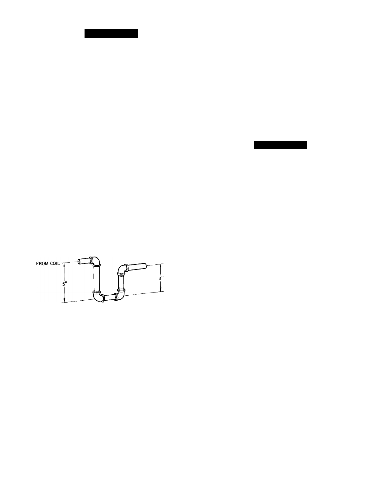
Install a 3-in. trap at the drain fitting to ensure proper
drainage. See Fig. 3. Make sure trap outlet is at least 2 in.
lower than unit dredn pan connection to prevent pan from
overflowing. Prime trap with water.
TO DRAIN
Fig. 3—Condensate Trap
If installation requires draining the condensate water away
from unit, connect a dredn tube using a minimum of 7s-in. OD
copper tubing, %-in. galvanized pipe or 7s-in. plastic pipe. Do
not undersize the tube. Pitch drain tube downward at a
slope at least one in. for every 10 ft of horizontal run. Be
sure to check drain tube for leaks.
Condensate water can be drained directly onto roof in roof
top installations (where permitted) or onto a gravel apron in
ground level installations. When using a gravel apron, make
sure it slopes away from the unit.
VENTING—The vent cap, combustion air shroud and flue
assembly are shipped in either the blower or control com
partment. Vent screen is taped to blower housing. Remove
access doors to locate assemblies. See Fig. 4 for door
locations.
A CAUTION
Venting system is designed to ensure proper venting.
Vent cap assembly must be installed as indicated
below.
NOTE: Screw holes in flue assembly and unit top eire posi
tioned to ensure proper orientation when installed. Refer to
Fig. 5 emd instedl vent cap as follows:
1. Place combustion air shroud over combustion air open
ing in unit top, and line up screw holes in shroud with
holes in top. Secure shroud to top, using screws with
rubber washers (provided).
2. The flue gasket is shipped in the literature assembly
envelope. Place gasket and flue assembly through hole
in combustion air shroud, orient screw holes in base of
flue assembly with holes in unit top, and secure gasket
and flue assembly to unit top, using screws provided.
3. Form flat wire screen (provided) into circular shape
around protruding lip of combustion-air shroud and
bend wire ends through holes of screen mesh to secure
screen in place. Make sure that no sharp edges are left
exposed.
4. Place vent cap sleeve inside flue assembly. Orient
spring chp of vent cap with slot in assembly. Be sure
clip snaps into slot to secure clip onto assembly.
Page 4
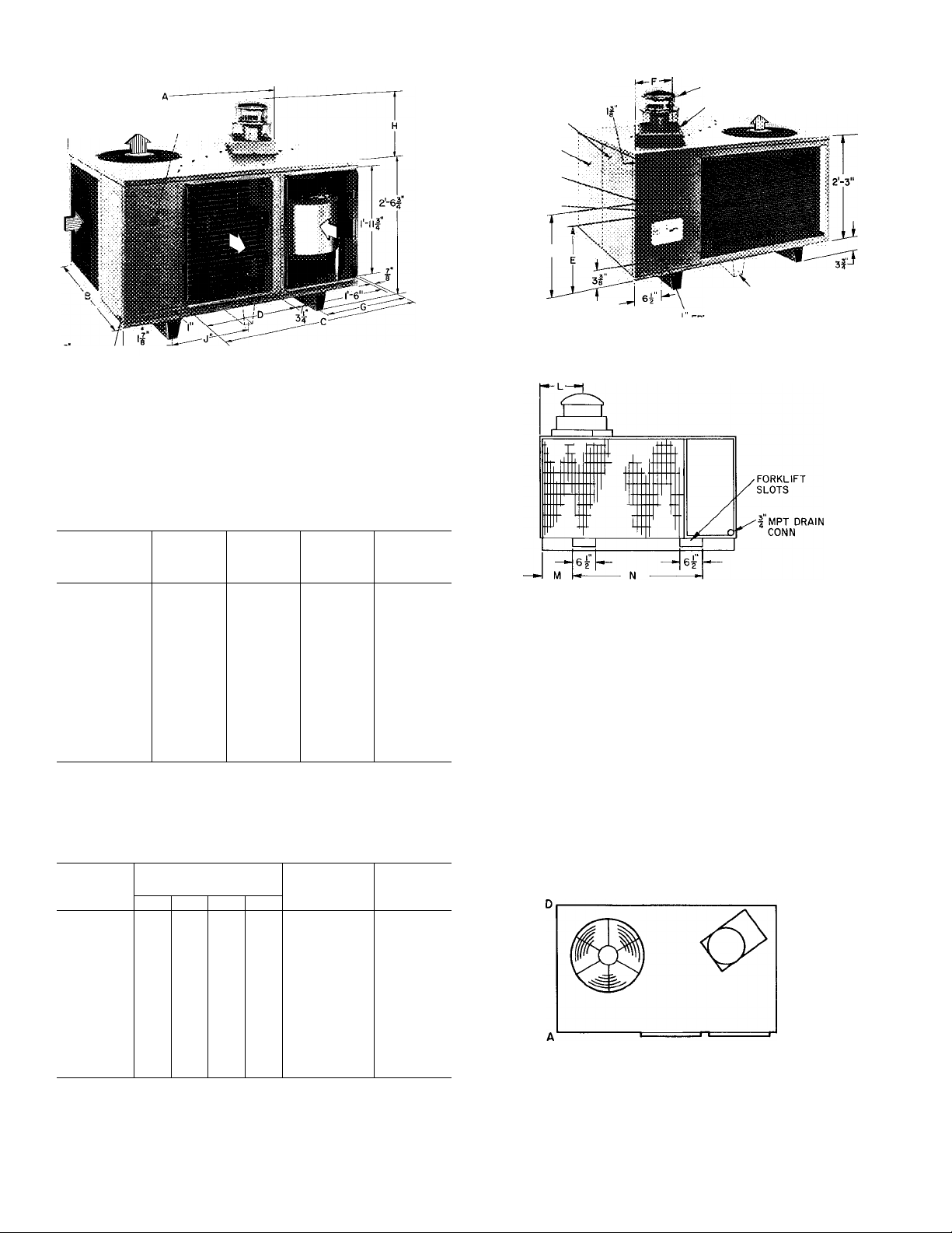
i MPT / U-—G
DRAIN CONN
PLUGGED ACCESS HOLE
FOR REFRIGERANT
PRESSURE GAGE HOSES
*NOTON MODELS48KLAII8THROUGH
I36i KHA024 THROUGH 030
CONTROL ACCESS
DOOR
BLOWER ACCESS
DOOR
I LOW VOLTAGE
INLET
K HIGH VOLTAGE
INLET
T-4Í
C> EVAPORATION AIRFLOW
^CONDENSER AIRFLOW
VENT CAP
COMBUSTION AIR INLET BOX
■NOT ON MODELS
48KLAII8 THROUGH 136;
KHA024 THROUGH 030
MODEL 48-
Dimensions
(ft-in.)
A
B
C
D
E
F
G
H
J
K
L
M
N
MODEL
48-
KLA118 82
KLA124
KHA024
KLA130
KHA030 97
KLA136
KHA136 122
KHA036
KLA142
KHA042
KLA148 130 135 137
KHA048 134 139 144
KLA160
KHA060
KLA118
KLA124
4-5% 4-5% 5-5%
2-6% 3-4% 3-8%
3-2'/a
1-4 1-7 2-0
1-4 1-4
0-7'/4
0-11% 0-10% 0-10%
1-3’A
—
0-1 %2 0-1% 0-1% 0-1%
0-1%
0-47,6
1-10 2-4 2-4
CORNER WT (ib)
A B
83 81
96 94
97 93
98 97 92
122 120 116 117 475 485
108 105 102
113 111 107
148 144 139
155 151
C D
79
93 91 94 375 385
120 116 117
148 151 605
KHA024
KLA130
KHA030
KLA136
3-57s 3-107e
0-8?8
1-374 1-874
—
0-17e
0-67,6
79 81 320 330
82
79
91 94 375 385
90 92 372 382
93 380
105 420
109 440
133 535
138 555
144 575
KHA136
KHA036
KLA142
KHA042
1-174
0-8%
1-1 O'732
1-4
0-87,6 0-87,6
TOTAL
OPERATiNG
WT (ib)
325 335
475
KLA148
KHA048
KLA160
KHA060
6-0%
3-8%
4-6%
2-8
1-174
0-8%
0-11%
1-8%
2-0=»/32
1-5
2-4
TOTAL
SHiPPING
WT (ib)
390
485
430
450
545
565
585
615
Above flue vent........................................................................................................3-0
Duct side of unit .....................................................................................................0-6
Side opposite ducts................................................................................................2-6
Biower access panel side.
Side opposite biower access panel.
Bottom of unit.................................................
NOTE: Provision must be made for fresh ambient air to reach the
outdoor coil without recirculation of the air from the outdoor fan
discharge
Weight Data
VIEW AA
CLEARANCES (ft-in.)
2-6
2-6
0
Fig. 4—Dimensions and Ciearances (ft-in.)
Page 5
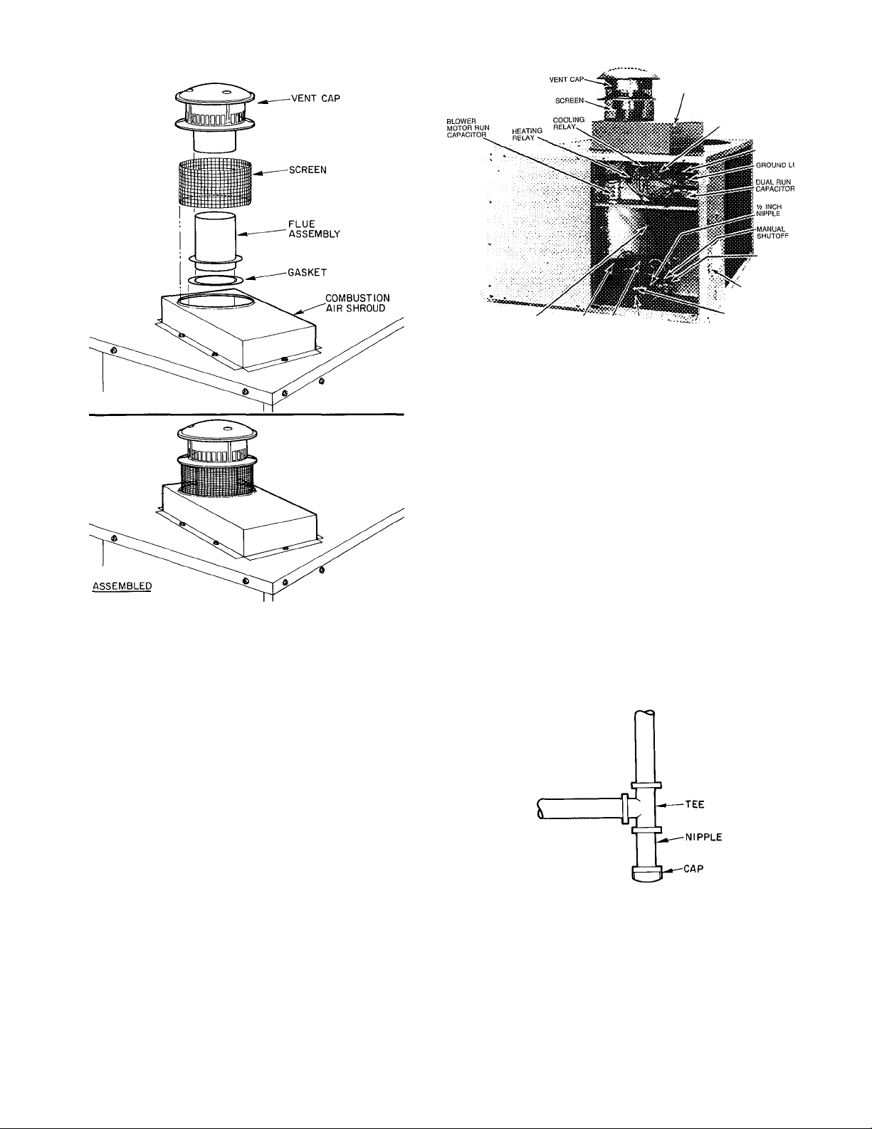
Fig. 5—Vent Cap Assembly
COMBUSTION-AIR SHROUD
CONTROL
TRANSFORMER
COMPRESSOR
CONTACTOR
GAS INLET
PRESSURE TAP
(BACK SIDE)
‘GAS PIPE
ENTRANCE HOLE
REGULATOR
LOW VOLTAGE SECONDARY p. pf'TpoNIC \
WIRES air SHIELD ^^)n7rOL GAS VALVE
HEAD
ADJUSTING SCREW
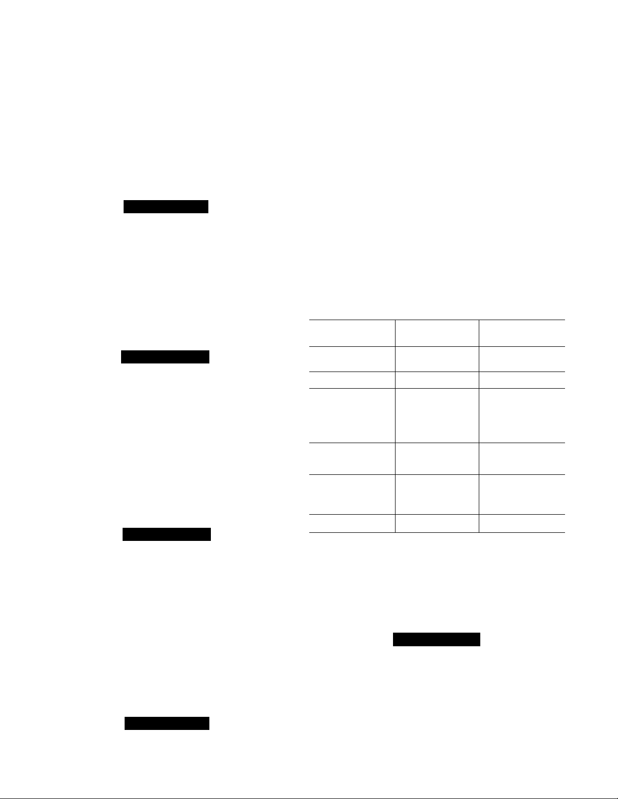
Fig. 6—Model 48KLA136—Side View
(Partiai) with Access Doors Removed
2. Protect all segments of piping system against physiceJ
and thermal deimage. Support all piping with appropri
ate hangers, etc. Use a minimum of one hanger in every
6 feet. For pipe sizes larger them V2-in., follow recom
mendations of national codes.
Apply joint compound (pipe dope) speiringly and only
3.
to male threads of joint when meiking pipe connections.
Use only pipe dope that is resistant to action of lique
fied petroleum gases as specified by local and/or
nationeJ codes. Never use pipe thread tape.
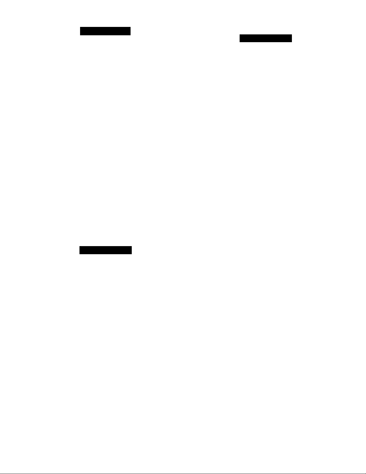
InsteJl a sediment trap in riser leading to the heating
4.
section. See Fig. 7. This drip leg functions as a trap for
dirt and condensate. Install trap where condensate can
not freeze. Install this sediment trap by connecting a
piping tee to riser leading to heating section, so that
straight-through section of tee is vertical. Then, con
nect capped nipple into lower end of tee. Extend
capped nipple below level of gas controls.
Step 2—Make Gas Piping Connections—A manual shutoff
vedve is shipped loose in the burner compartment or blower
compartment. Connect one end of a field-supplied V2-in.
streught nipple to the gas valve inlet. Connect the other end
of the nipple to the manual shutoff valve as shown in Pig. 6.
The gas supply pipe enters unit through access hole pro
vided. See Fig. 4 for location. The gas connection to unit is
made to the V2-in. FPT gas inlet on manual shutoff. See Fig.
6 for inlet location.
Install a separate gas supply line that runs directly from
meter to heating section. Do not use cast-iron pipe. Check
local utility for recommendations concerning existing lines.
Choose a supply pipe that is large enough to keep pressure
loss as low as practical. Never use pipe smaller than the ^¡¿-in.
FPT gas inlet on unit manual shutoff.
When installing gas supply line, observe local codes pertain
ing to gas pipe installations. Refer to National Fuel Gas
Code, NFPA 54-1984/ANSI Z223.1-1984 in absence of local
building codes. Adhere to following pertinent recom
mendations:
1. Avoid low spots in long runs of pipe. Grade all pipe %-
in. in every 15 ft to prevent traps. Grade all horizonteJ
runs downward to risers. Use risers to connect to heat
ing section and to meter.
Fig. 7—Sediment Trap
5. Install an accessible, external, manual shutoff valve in
gas supply pipe within 6 ft of heating section.
NOTE: The unit manual shutoff valve has a Vs-in. tap
ping on the inlet side of this shutoff for measuring gas
input pressure.
6. Install ground-joint union close to heating section
between unit manual shutoff and external manual main
shutoff valve.
Page 6
7. Pressure-test all gas piping in accordance with loceil
and national plumbing and gas codes before connecting
piping to unit.
NOTE: When pressure-testing the gas supply system
after the gas supply piping has been connected to the
unit gas valve, the supply piping must be disconnected
from the gas valve during any pressure testing of the
piping systems at test pressures in excess of 0.5 in.
psig. When pressure testing the gas supply piping sys
tem at test pressures equal to or less than 0.5 in. psig,
the unit heating section must be isolated from the gas
piping system by closing the external main manual
shutoff valve and slightly opening ground-joint union.
A CAUTION
Unstable operation may occur, peirticularly under highwind conditions, when gas valve and manifold assembly
are forced out of position while connecting improperly
routed, rigid gas piping to gas valve. Use a backup
wrench when making connection to avoid strain on, or
distortion of, gas control piping.
2. Use a flexible transition between rigid ductwork and
unit to prevent transmissions of vibration. The transi
tion may be screwed or bolted to duct flanges. Use suit
able gaskets to ensure a weathertight and air-tight
seal.
3. Install external, field-supplied air filter(s) in return-air
ductwork where it is easily accessible for service. Rec
ommended filter sizes are shown in Table 2.
4. Size all ductwork for maximum required airflow (either
heating or cooling) for unit being installed. Avoid
abrupt duct size increases or decreases.
5. Adequately insulate and weatherproof all ductwork
located outdoors. Insulate ducts passing through an
unconditioned space, and use a vapor barrier in accord
ance with the latest issue of SMACNA and NE SC A
minimum installation standards for heating and air
conditioning systems. Secure all ducts to building
structure.
6. Flash, weatherproof and vibration-isolate all openings
in building structure in accordance with local codes and
good building practices.
8. Where permitted by local codes, use an approved corru
gated metal tubing gas connector between rigid gas
piping and unit manual shutoff.
A WARNING
Never use a match or other open flame when checking
for leaks. Failure to adhere to this warning may cause
an explosion.
9. Check for gas leeiks at eJl field-installed and factoryinstalled gas lines after all piping connections have
been completed. Use soap-and-water solution (or
method specified by local codes and/or regulations).
Step 3—Make Duct Connections—Model 48KHA,KLA
has duct flanges on the supply- and return-air openings on
side of unit. See Fig. 4 for connection sizes and locations.
A WARNING
The design and installation of duct system must be in
accordance with standards of National Fire Protection
Association for installation of non-residence type air
conditioning and ventilating systems. NFPA No. 90; or
residence-type NFPA No. 90B; and/or local codes and
ordinances.
Table 2—Filter Sizes (Field Supplied),
(Sq In.)*
MODEL 48-
KLA118310BE
KHA024310BF
KLA124310BE
KHA030310BF
KLA130310BE
KHA036310BF
KHA136510CE
KHA036510CF
KHA136310BE
KLA136510CE
KLA136610CE
KLA136310BE
KHA042310BF 694
KHA042510CF 694
KLA142510CE
KLA142310BE 672
KHA048310BF 768
KHA048510CF 768
KLA148510CE 768
KLA148610CE
KLA148310BE
KHA060310BF 960
KLA160310BE 960
*Required air filter areas shown are based on the ARI-rated cooling air
flow or the heating airflow at a velocity of 300 fpm depending on
whichever value is larger. Air filter pressure drop should not exceed 0 08
, in wg
STANDARD CLEANABLEOR
DISPOSABLE HIGH CAPACITY
TYPE
302 202
454
384 257
480 320
480 320
694
576
694
576
576
576 384
576 384
672
768 512
768 512
TYPE
303
462
384
462
384
384
462
462
448
448
512
512
512
640
640
Step 4—Make Wiring Connections
Adhere to the following requirements when selecting, sizing
tmd installing duct system;
1. Select and size ductwork, supply-air registers and
return-£ur grilles according to ASHRAE recommenda
tions emd as presented in Carrier System Design Man
ual, Part 2.
A CAUTION
When duct system fastening holes are drilled into side
of Model 48KHA,KLA instead of the unit duct flanges,
use extreme care to avoid puncturing coil or coil tubes.
A WARNING
Unit cabinet must have an uninterrupted, unbroken
electrical ground to minimize the possibility of personeil
injury if an electrical fault should occur. This ground
may consist of electrical wire connected to unit ground
lug in control compartment, or conduit approved for
electrical ground when installed in accordance with
National Electrical Code ANSI/NFPA 70-1984 and
local electriced codes. Do not use gas piping as an elec
trical ground. Failure to follow this warning could
result in the installer being held liable for personal
injury of others.
Page 7
A CAUTION
Feiilure to follow these precautions could result in dam
age to unit being installed.
1. Make all electrical connections in accordance with
National Electrical Code ANSI/NFPA 70-1984 and
local electrical codes governing such wiring.
2. Use only copper conductor for connections between the
field-supplied electrical disconnect switch and the unit.
Do not use aluminum or copper-clad aluminum wire.
3. Ensure that high-voltage power to unit is within oper
ating voltage range indicated on unit rating plate. On
3-phase units, ensure that phases are balanced within
2%. Consult local power company for correction of
improper voltage and/or phase balance.
4. When low-voltage control wires are run in same conduit
as high-voltage wires, insulate low-voltage wires for
highest voltage contained within conduit.
5. Do not damage internal components when drilling
through any panel to mount electrical hardware, con
duit, etc.
HIGH-VOLTAGE CONNECTIONS-Unit must have a
sepeirate electriceil service with a field-supplied, waterproof,
fused disconnect switch per NEC mounted near, and within
sight from, the unit. Refer to unit rating plate for maximum
fuse size and minimum circuit amps (ampacity) for wire siz
ing. Table 3 shows recommended wire sizes and lengths
based on rating plate data.
The field-supplied disconnect switch box may be mounted
on unit over the high-voltage inlet hole in control corner
pemel. See Fig. 4.
A WARNING
Label Part No. A74191B, which is shipped loose in bag
of parts, must be affixed to the disconnect switch box.
This label states: "DO NOT DISCONNECT THE
ELECTRICAL POWER TO THIS APPLIANCE
WITHOUT FIRST TURNING OFF THE GAS
SUPPLY.”
Proceed as follows to complete the high-voltage connections
to unit:
1. Connect ground lead to chassis ground connection
when using a separate ground wire.
2. Run high-voltage leads into unit control box and con
nect to contactor. See unit wiring label and Fig. 6
and 8.
NOTE; On 3-phase units, connect third high-voltage lead to
brown high-voltage pigtail lead. See unit wiring label and
Fig. 8.
SPECIAL PROCEDURES FOR 208-V OPERATION
A WARNING
Make sure power supply to unit is switched OFF before
making any wiring changes. Electrical power may cause
personal injury or death.
For operation on 208 volts, disconnect orange transformer
primary lead from contactor. See unit wiring label and
Fig. 6. Remove tape emd cover from terminal on end of red
transformer-primary lead. Save cover. Connect red lead to
contactor terminal from which orange lead was dis
connected.
Using cover removed from red lead, insulate loose terminal
on orange lead. Wrap cover with electricEd tape so that
metal terminal cannot be seen.
NOTE: For some 48KHA,KLA units, the factory-wired
blower-motor speed connections may require changing for
208-v operation to ensure adequate airflow at the rated
external static pressure. See unit wiring label. Insulate all
unused motor leads following same procedures described for
tremsformer leads.
LOW-VOLTAGE CONNECTIONS-Use a suitable room
thermostat as specified on unit wiring label.
Locate room thermostat on an inside wall in space to be con
ditioned where it will not be subjected to either a cooling or
heating source, or direct exposure to sunlight. Mount ther
mostat 4 to 5 ft above floor.
Use no. 18 AWG color-coded, insulated (35 C minimum)
v/ires to make low-voltage connections between thermostat
and unit. If thermostat is located more than 100 ft from
unit (as measured along the low-voltage wires), use no. 16
AWG color-coded, insulated (35 C minimum) wires.
A grommeted, low-voltage inlet hole is located in the panel
adjacent to control access panel. See Fig. 4. Run low-voltage
leads from thermostat, through inlet hole and to low-voltage
flagged pigtail leads that run through a hole in bottom of
unit control box. See Fig. 6. Connect thermostat leads to
pigtail leads as shown in Fig. 8
HEAT ANTICIPATOR SETTING—Room thermostat heat
anticipator must be properly adjusted to ensure proper
heating performance. Set heat anticipator, using ammeter
to determine exact required setting.
NOTE: For thermostat selection purposes, use 1.0 amps for
approximate required setting.
Failure to make a proper heat anticipator adjustment will
result in improper operation, discomfort to occupants of
conditioned space and inefficient energy use; however,
required setting may be changed slightly to provide a
greater degree of comfort for a particular installation.
Page 8

MODEL
48-
KLA118
SERIES
310BE 208/230-1 197
VOLTSPHASE
KLA124 310BE 208/230-1
KHA024 310BF
KLA130
KHA030
KLA136
KLA136
KLA136
KHA136
KHA036
310BE 208/230-1
310BF 208/230-1 197
310BE 208/230-1
510CE 208/230-3
610CE
310BE
310BF
KHA136 510CE,CF
KHA036 510CF
KLA142
310BE 208/230-1
208/230-1 197
460-3 414
208/230-1
208/230-3 187 253
208/230-3 187
KLA142 510CE 208/230-3
KHA042
310BF 208/230-1
KHA042 510CF 208/230-3
KLA148 310BE
KLA148
510CE 208/230-3
KLA148 610CE
KHA048
KHA048
KLA160
KHA060
310BF
510CF 208/230-3
310BE 230-1
310BF
208/230-1 197
460-3 414
208/230-1 197
230-1 207
AWG—American Wire Gage
FLA —Full Load Amps
IFM —Indoor Fan Motor
LRA —Locked Rotor Amps
MCA—Maximum Circuit Ampacity
OFM —Outdoor Fan Motor
RLA —Rated Load Amps
Table 3—Electrical Data (60 Hz)
OPERATING
VOLTAGE* COMPR
Min Max RLA LRA
253 8.7 49.0 1.2
197 253
197 253
197 253
187 253
197 253
197 253
187
197 253
187
187 253
187 253
207 253
11.7 63.0 1.7 1.0
253 11.7 63.0
13.7
253 13.7 76.0 2.9
506 5.1 32.8 1.9
253
253
253
253
506
253
253
*Voltage limits between which the unit will operate satisfactorily
tif other than 75 C copper wire is used, determine size from unit ampacity and the National Elec
trical code. Voltage drop of wire must be less than 2% of unit rated voltage Maximum wire
length is for one way along the wire path from unit to service panel
:(;Maximum dual element size
76.0
17.6 88.0 4.6
11.5 65.1 4.7 1.0 20.1
17.6 88.0 3.8 0.8 26.6
65.1 5.6 1.0 21.0 18.1
11.5
11.5 65.1 5.6 1.0 21.0 18.1
95.4 4.1
23.9
15.3 82.0 5.6 1.0 25.8 21.9
95.4 3.9 0.8 34.6 28.6 50
23.9
15.3 82.0 5.0 1.0
23.7 116.0 4.5
14.7 92.0 7.8
7.0
23.7 116.0
14.7
130.0 6.2 1.9 42.9 35.9
27.8
27.8 130.0 6.5
MAX FUSE
FLA
IFM
3.0 1.0
3.1 1.0
46.0 3.3 1.2 13.3 11.5 20
3.7 1.9 35.3 29.3 50 8
92.0 5.8 2.2 26.4 22.7 35
MCAt
OFM
1.0 13.1 10.9
1.0 21.0
1.0 27.6 23.2
0.6 8.9 7.6 15
0.8
1.9 36.1 30.1 50 8
2.2
1.9 43.2 36.2 60
MAX
AMPS
17.4 14.4 25
18.7 15.7 25
21.2 17.8 30 10 115
34.8 28.8 50
25.2 21.3 35 10
28.4
17.6 30 10 116
17.2 25
22 2 40
24.7 35 10
SIZE
(Amps)t
20
40 10
25 10 130
25 10 130
35 10 108
60 8
MIN WIRE
SIZE (AWG)t
(75C Copper)
14
12
12
10
14 272
10
8 113
8 114
14 180
10
8 99
MAX
WIRE
LENGTHt
76
89
82
88
137
92
111
108
96
111
104
100
SINGLE-STAGE HEAT S COOL-
MANUAL CHANGEOVER
. Field Low-Voltage Wiring
.Field High-Voltage Wiring
. Factory Low-Voltage Wiring
, Factory High-Voltage Wiring
SINGLE-STAGE HEAT S COOL-
AUTOCHANGEOVER
JUMPER-H
NOTE: For manual changeover applications, use thermostat part no. HH01AD042 with
subbase part no HH93AZ042, or thermostat part no HH01AD040 with subbase part no
HH93AZ040
For automatic changeover, use thermostat part no. HH07AT174 with subbase part no.
HH93AZ096; or thermostat part no HH10AD041 with subbase part no HH93AZ041.
-------------------
HIGH-VOLTAGE
PIGTAIL LEAD
1
—♦frrw^
-------
3-PHASE
UNITS ONLY
CONTACTOR TERMINALS
(SEE UNIT WIRING LABEL)
---
'
>n-rvri —
FIELD-SUPPLIED
DISCONNECT PER NEC
Fig. 8—High- and Low-Voitage Connections
Page 9

STARTUP
Unit Preparation
A WARNING
Failure to observe the following warnings could result
in serious personal injury;
1
Follow recognized safety practices and wear protective
goggles when checking or servicing refrigerant system.
Do not operate compressor or provide any electric
2.
power to unit unless compressor terminal cover is in
place and secured.
3.
Do not remove compressor terminal cover until all elec
trical sources have been disconnected.
4.
Relieve all pressure from system before touching or dis
turbing anything inside terminal box if a refrigerant
leak is suspected around compressor terminals.
5. Never attempt to repair a soldered connection while
refrigerant system is under pressure.
6. Do not use a torch to remove any component. System
contains oil and refrigerant under pressure. To remove
a component, wear protective goggles and proceed as
follows:
a. Shut off gas supply first, and then electrical power
to unit.
b. Relieve all pressure from system.
c. Use tubing cutter to cut tubing that connects com
ponent, and remove component from unit.
d. Carefully unsweat remaining tubing stubs when
necessary. Oil can ignite when exposed to torch
flame.
PRE-START-UP PROCEDURES-Proceed as follows to
inspect and prepare unit for initial start-up:
Remove edl access panels.
Read and follow instructions on all WARNING, CAU
TION and INFORMATION labels attached to or Heating Section Start-Up and Adjustments
shipped with the unit.__________________________________________________________________
3.
Make following inspections:
a. Inspect for shipping and handling damages such as
broken lines, loose parts, disconnected wires, etc.
b. Inspect for oil at all refrigerant tubing connections
and on unit base. The presence of oil generally indi
cates a refrigerant leeik. Leak-test all refrigerant
tubing connections using electronic leak detector,
halide torch or liquid soap solution. If refrigerant
leak is detected, see Refrigerant Leaks in next
section.
c. Inspect all field- and factory-wiring connections. Be
sure connections are completed and tight.
d. Inspect coil fins. If damaged during shipping and
handling, carefully straighten fins with a fin comb.
c. Maike sure air filter(s) is in place.
d. Make sure condensate dredn pan is filled with water
to ensure proper drainage.
e. Make sure all tools and miscellaneous loose parts
have been removed.
5. Replace all access panels. Unit is now ready for initial
start-up.
REFRIGERANT LEAKS—Proceed as follows to repair a
refrigerant leak and to charge the unit.
A WARNING
Never attempt to repair a soldered connection while
refrigerant system is under pressure. Severe bodily
injury may result. Always wear protective goggles
when servicing the refrigerant system.
1. Locate leak and ensure that refrigerant system pres
sure has been relieved.
2. Repair leak following accepted practices.
NOTE; Install a filter drier whenever system has been
opened for repair.
3. Add a small cheu-ge of R-22 refrigerant vapor to system
and leEik-test unit.
4. Evacuate refrigerant system if additioned leaks are not
found.
5. Charge unit with R-22 refrigerant, using a volumetric-
charging cylinder, such as Dial-a-Charge, or accurate
scale. Refer to unit rating plate for required charge. Be
sure to add extra refrigerant to compensate for interned
volume of filter drier.
NOTE: See Cooling Section Start-Up and Adjustments—
Checking and Adjusting Refrigerant Charge.
A CAUTION
Complete required procedures given in Unit Prepara
tion section before starting unit.
Do not jumper any safety devices when operating unit.
Ensure that burner orifices are properly aligned. Unstable
operation may occur when the burner orifices in the mani
fold are misedigned. To ensure correct burner orifice edignment, check orifice angle with a machinist’s protractor or
other suitable device. The orifice angle must be from hori
zontal to 3 degrees down, as measured from unit base.
Follow instructions on heating section operation label
(located in unit near the gas valve) or in Owner’s Manual, to
start the heating section.
A WARNING
Do not purge gas supply into combustion chamber. Do
not use a match or other open flame to check for gas
leaks. Failure to adhere to this warning may cause an
explosion.
4. Verify the following conditions:
a. Meike sure gas supply has been purged, and all gas
piping has been checked for leaks.
b. Make sure outdoor fan blade is correctly positioned
in fan orifice. Blades should clear fan motor by no
more than % inch.
CHECKING HEATING CONTROL OPERATION-Start
and check unit for proper heating control operation as
follows:
Place room thermostat selector switch in HEAT position
and fan switch in AUTO, position. Set heating temperature
control of thermostat above room temperature. Observe
that after built-in time delays, the pilot automatically
lights, burners light and blower motor starts. Observe that
burners and pilot are extinguished, and that after a built-in
delay, blower motor stops when heating control setting of
thermostat is satisfied.
_____
_
Page 10

GAS INPUT
A CAUTION
These units are designed to consume the rated gas
inputs using the fixed orifices at specified manifold
pressures as shown in Table 4. DO NOT REDRILL
ORIFICES UNDER ANY CIRCUMSTANCES.
The rated gas inputs shown in Table 4 are for altitudes from
sea level up to 2000 ft above sea level. These inputs are
based on natureJ gas with a heating value of 1050 Btu/cu ft
at 0.65 specific gravity, or propane gas with a heating value
of 2500 Btu/cu ft at 1.5 specific gravity. For elevations
above 2000 ft, reduce input 4% for each 1000 ft above sea
level. When gas supply being used has a different heating
value or specific gravity, refer to Carrier training manuals,
national and local codes, or contact your Carrier distributor
or dealer to determine required orifice size.
ADJUSTING GAS INPUT-The gas input to unit is deter
mined by measuring the gas flow at the meter or by measur
ing the manifold pressure. Measuring the gas flow at the
meter is recommended for natured gas units. Manifold pres
sure must be measured to determine the input of propane
gas units.
Measuring Gas Flow at Meter Method—Natural Gas
Units—Minor adjustment can be made by changing mani
fold pressure. Manifold pressure must be maintained
between 3.2 and 3.8 in. wg. If larger adjustments are
required, change main burner orifices following recommen
dations of national and loced codes.
NOTE: All other appliances that use the same meter must
be turned off when gas flow is measured at meter.
Proceed as follows:
1. Turn off gas supply to unit.
2. Remove pipe plug on bottom of gas vedve, then connect
water manometer at this point. Turn on gas to unit.
3. Record number of seconds for gas meter test dial to
make one revolution.
4. Divide number of seconds in step 3 into 3600 (number
of seconds in one hour).
5. Multiply result of step 4 by the number of cu ft shown
for one revolution of test dial to obtain cu ft of gas flow
per hour.
6. Multiply result of step 5 by Btu heating value of gas to
obtain toted measured input in Btuh. Compare this
value with heating input shown in Table 4. Consult
local gas supplier if the heating value of gas is not
known.
Example: Assume that the size of test dial is one cu ft, one
revolution takes 30 seconds and the heating value of the gas
is 1050 Btu per cu ft, then proceed as follows;
a. 30 seconds to complete one revolution.
b. 30 divided into 3600 equals 120.
c. 120 times one equals 120 cu ft of gas flow per hour.
d. 120 times 1050 equals 126,000 Btuh input.
If the desired gas input is 125,000 Btuh, only a minor
change in the manifold pressure is required.
Observe manifold pressure and proceed as follows to adjust
gas input:
1. Remove cover screw over REG ADJ screw on gas
valve.
2. Turn regulator adjustment screw clockwise to increase
gas input, or turn regulator adjustment screw counter
clockwise to decrease input. Manifold pressure must be
between 3.2 and 3.8 in. wg. UNSAFE OPERATION
OF THE UNIT MAY RESULT IF MANIFOLD
PRESSURE IS OUTSIDE THIS RANGE.
3. Replace vented seal on gas valve.
4. Turn off gas supply to unit. Remove manometer from
pressure tap. Replace pipe plug on gas valve. Turn on
gas to unit. Check for leaks.
Measuring Manifold Pressure—Propane Gas Units—The
main burner orifices on a propane gas unit are sized for the
unit rated input when manifold pressure is 10.5 in. wg.
Proceed as follows to adjust gas input on propane gas unit:
1. Turn off gas to unit.
2.
Remove pipe plug on gas valve outlet identified as
PRESS. TAP, then connect manometer at this point.
3.
Turn on gas to unit.
4. Remove cover screw over REG ADJ screw on gas
valve.
5.
Adjust regulator adjustment screw for a manifold pres
sure reading of 10.5 in. wg. Turn adjusting screw clock
wise to increase manifold pressure, or turn adjusting
screw counterclockwise to decrease manifold pressure.
Replace cover screw.
6.
7.
Turn off gas to unit. Remove manometer from pressure
tap. Replace pipe plug on gas valve, then turn on gas to
unit. Check for leaks.
Table 4—Rated Gas Inputs at Indicated Manifold Pressures
GAS SUPPLY NATURAL GAS PROPANE GAS
NUMBER
MODEL 48-
KLA118,124,130
KLA136,142 3 5.0
KHA024,030
KLA148
KHA136,KLA160
KHA036,042,048 5 5.0
KHA060 6 5.0
♦Based on altitudes from sea level up to 2000 ft above sea level. For alti
tudes above 2000 ft, reduce input rating 4% for each 1000 ft above sea
levei
OF Natural
ORIFICES Min Max
2 5.0 13.6 11.0
3 5,0
4 5.0 13.6
5 5.0 13.6
PRESSURE (in. wg) PRESSURE
13.6 11.0
13.6 11.0
13.6 11.0
13.6 11.0 13.0 3.5 10.5
Propane (in. wg)
Max Natural
Min
13.0 3.5 10.5
13.0 3.5 10.5
13.0 3.5
13.0 3.5
11.0
11.0 13.0 3.5 10.5
13.0 3.5
Orifice
Propane
10.5 LH32DB207(42) 75,000 LH32DB060(53) 75,000
10.5 LH32DB205(45) 80,000 LH32DB201(55)
10.5
fWhen KLA is converted to propane, all
See kit instructions
Part No. Input Part No. input
(Size)
LH32DB204(45) 40,000 LH32DB201(55)
LH32DB205(45) 60,000 LH32DB201(55)
LH32DB205(45)
LH32DB207(42) 125,000
LH32DB207(42) 150,000
Heating
(Btuh)* (Size) (Btuh)*
100,000 LH32DB201(55)
Orifice
LH32DB060(53)
LH32DB060(53)
NOx burners must be modified
10
Heating
40,000t
60,000t
80,000t
ioo,ooot
125,000
150,000
Page 11

ADJUSTING BURNER AIR SHUTTERS-After burners
have operated at full input for at least 10 minutes, adjust
primary air to each burner to ensure optimum heating per
formance. Make these adjustments when unit is being
installed and during routine maintenance inspections at
beginning of each heating season. Be sure each burner is
clean and free of deposits before adjusting primary air.
Primary air to each burner is regulated by burner air shut
ter on each burner. See Fig. 9 (Burner Flames, Standard) for
location of burner air shutter. With all burners operating,
adjust primary air to each burner as follows:
1. Loosen locking screw that secures air shutter in place
on burner, then partially close air shutter until a slight
yellow tip appears on top of burner flames.
2. Open air shutter very slowly until yellow tip just disap
pears, then secure air shutter in place with locking
screw.
3. Repeat steps 1 and 2 for each burner.
After air shutter adjustments have been completed, observe
that flames on each burner are light blue and soft in appear
ance, and that flames are same height along entire length of
each burner. See Fig. 9.
CARRYOVER
AIR
SHUTTER
STANDARD
MANIFOLD
Fig. 9—Burner Flames
BLOWER HEAT-RELAY OPERATION-Heating relay
(see Fig. 6 and unit wiring diagram) is located in the control
box and adjusts to permit either longer or shorter OFF
cycles. The ON cycle automatically adjusts as OFF cycle
changes. Adjusting level on relay is factory-set at center
position to provide optimum performance for most installa
tions. On unusual installations, or where line voltage is con
siderably above or below rated voltage, an increase or
decrease may be required for length of time blower remains
on. To increase blower operation time, move adjusting lever
toward right-hand position. To decrease blower operation
time, move lever toward left-hand position.
AIRFLOW AND TEMPERATURE RISE-The heating
section of each size of unit is designed and approved for
heating operation within temperature rise range stamped on
unit rating plate.
Table 5 shows approved temperature rise range for each
unit and air delivery (cfm) at various temperature rises.
Heating operation airflow must produce a temperature rise
that falls within the approved range. Refer to Cooling Sec
tion Start-Up and Adjustments—Indoor Airflow emd Air
flow Adjustments to adjust heating airflow when required.
HEATING SEQUENCE OF OPERATION—See Fig. 10
Models 48KHA,KLA have an intermittent electric-spark
ignition system without a standing flame. When manual
shutoff is opened, gas flows to gas valve. On a call for heat
ing by the thermostat, unit terminal R makes to unit termi
nal W. Pilot veJve solenoid of gas valve and spark generator
are energized. Gas flows to pilot and the pilot is ignited
within 4 seconds. The flame sensor proves the presence of
pilot flame within 0.8 seconds after pilot ignition. The inter
nal switching of gas valve de-energizes spark generator,
energizes meun valve solenoid and energizes heating delay
relay. Gas flows to medn burners and is ignited by pilot
flame. Contacts of heating relay close between 60 and 90
seconds after burners are ignited, and blower motor starts.
Heating cycle is now in normeil operation. Unit will continue
operating in heating cycle until thermostat is satisfied.
When this occurs, the thermostat switching removes 24-volt
control circuit voltage instantly; however, contacts of de
energized heating relay remain closed and keep blower
motor running for an additional 2 to 3 minutes. Contacts of
heating relay open after 2- to 3-minute delay and blower
motor stops. Heating section is now in a standby condition
wmting for another call for heating from thermostat.
Table 5—Air Delivery (cfm) at Indicated Temperature
MODEL 48-
KLA118
KLA124 40,000 794 751 712 678 646
KHA024 75,000
KLA130
KHA030
KLA136
KHA036/136
KHA036 125,000
KLA142 60,000 1190
KHA042 125,000
KLA148 80,000
KHA048
KLA160 100,000
KHA060 150,000
NOTE: Bolder ratings in table fall
range of the unit Dashed areas of
HTG
INPUT TEMPERATURE RISE(F)
(Btuh)
40,000 794 751 712 678
40,000 794 751 712
75,000
60,000 1190 1126
100,000
125,000
35 37 39 41 43 45 47
— — — — 1212 1158
—
1984 1877 1781 1694 1615
— — —
1128
— — ~
1502
1587
— —
1877
1984
— - — — —
678
—
1271
1016 969
1068
2117
1068 1016
—
1355
1425
2326 2117
1781 1694
below the approved temperature rise
the tabie faii beyond the air delivery
Rise and Rated Heating Input
49
646 617
617
617
646
1212 1158
926 887
1543
2019 1930 1846 1771
926
969
_
1930 1846
1292 1235 1182
1930
2019
1815 1543 1478
2325 2226
567 545 524
591
591 567 545
1063 1022 983
1109
591 567
1063 1022 983 947 914 883
1109
850
1417 1362 1310
1478
850 817 786 758 731 706 683 661
887
1771 1702 1638 1579 1523
1134 1089 1048 1010 975
1771 1702
1846
1417 1362
2135 2051
51 53
545 524
817 786
1701 1638
1638
1310
1974
capabiiity of the unit within the operating voitage range for aii voltage
options for each size unit.
57 59 61 63 65 67
55
505 487 471
947 914 883 854 827 809
505 487 471
758 731
1263 1218
1579 1523
1579
1263
1902
706
1177
1472
1482
942 911 —
1472
1523
1177
1218
1835 1773 1715 1660
441
455
455
854
683
1102 1068 1036 1006 978 951 926
1138
1378 1336 1296 1258 1223 1189 1158
1423
1378 1326 1296 1258 1223
1423
1423 1378
1102
1138
71 73 75
69
_
—
427
778
641 622 604 587 571 556
—
—
1336 1296
—
—
1561
1609
—
—
— — —
—
— —
—
—
_
—
1493 1483 1395
1516
11
—
1189
— —
—
—
—
—
—
Page 12

C — Contactor
Cap. — Capacitor
Comp — Compressor
GV — Gas Valve
IFM — Indoor Fan Motor
IFMC — Indoor Fan Motor Capacitor
IFR — Indoor Fan Relay (Cooling)
IFSS — Indoor Fan Safety Switch
LS — Limit Switch
OFM — Outdoor Fan Motor
P — Pilot (Safety, Flame Sensing)
PI — Pilot Igniter
QT — Quadruple Terminal
ST — Start Thermistor
TDR — Time-Delay Relay (Adjustable) (Heating)
Tran — Transformer
Fig. 10—Typical Wiring Diagram (48KHA030310 shown)
H— Wire Sleeve
O Component Connection (Unmarked)
o Component Connection (Marked)
------
— — Field Wiring
________
Field Ground Wiring
--------------Field Power Wiring
-Pl- Field Splice
• ■ Junction
-----
®— Junction (Thermostat to Subbase)
— ——— Alternate Start Thermistor Wiring
•
12
NOTES:
1 Use copper conductors only.
2 Compressor and fan motors thermally protected
3 Transformer pigtails: red208v; orange 230v;
insulate unused lead
4 Neutral for 240/416-v system for Canada only
5 If any of the original wire furnished must be
replaced, it should be replaced with wire of the
same type or its equivalent
6 Fan motor pigtails; red low, black high, insulate
unused lead
Page 13

UNIT
MODEL
48-
KLA118
KLA124
KHA024 208-
KLA130
KHA030
KLA136
KLA136
KHA036
KHA136
KHA036
KHA136 230-3
KLA142
KHA042
KLA148 208-
KLA148
KHA048
(See next page for applicable notes )
VOLTS- MOTOR
PHASE (60 Hz) SPEED
208- Coolt
230-1 High Heat):
208-
230-1 High Heat
230-1
208-
230-1
208-
230-1
208-
230-1
208/
230-3
460-3 Cool 1165
208- Coolf:
230-1
208/
208-
230-1
208/ Cool 965 960 955 940 930
230-3 High Heat
208-
230-1 High Heat 1705
208/ Cool
230-3 High Heat
230-1 High Heat
208/ Med Heat 1805 1800 1785 1765 1735
230-3
460-3 Cool 1490
208-
230-1
BLOWER EXTERNAL STATIC PRESSURE (in. wg)
Low
Low
Low Heat
High Highf:
Low Heatf:
High Heat
Low
High Heat
Low Heatf:
High Heat
Low Heatf:
High
Low Heat): 1185
High Heat 1535
Low Heat
High HeatL
Low Heat
Med Heat
High Heatf:
Low Heatt
High Heat
Low
Low Heat
Low Heatf:
Low HeatL
Low Heat):
High Heat
Low Heatt 1500
High Heat 2040
Low
High Heat
Table 6—Model 48KHA,KLA Air Delivery (cfm)*
at Indicated External Static Pressure and Voltage
COILt
0.0 0.1
Heat
740 700 660
700 665 625
795 750 705
Cool
745
Heatf:
895 850
Cool
865
980 930 875
Coolt
940
995 925 890
Cool);
935
1125
Cool
1080 1035 990
700
Cool
690 670 650 630 605 580
1325 1270 1210
Coolf:
1270 1220 1165
Heatt
1125
Cool
1085
1225 1165 1105
Cool
1175 1120 1065
950 945 940 930 915 900
Cool
945 940 935 925 910 890 — — —
1570 1500 1425
Coolf:
1475 1410 1345
1165 1155 1140
Cool
1155 1145 1125 1110 1085 1050 1015 960 855
Heat
1525
Cool):
1475
Cool): 1485
1280 1260 1240
1265 1245
1825 1765 1700 1630
Cool
1735 1670
1275 1270 1260 1240 1220 1195 1165 1135 1100
Coolf:
1270 1260
1625 1605 1575 1540 1500 1455 1400 1350 1295
Cool
1590 1565 1530 1490
2035 1980 1920 1855 1785
Cool
1915 1860 1800 1740 1675
855 850 835
Cool
855 845 830
1700 1635 1565 1495 1425
Cool):
1635 1575 1505 1440
Heatf: 970 965 960 945 935
2040 1980 1915 1850
Coolf:
1950 1890 1835
1410 1385 1355 1315 1255 1175
Cool
1390 1365 1330 1280 1215 1120 — — — 1535
Cool):
1650 1590 1535 1465
1405 1400 1395 1385 1365
1400 1395
1725 1710 1685 1655 1615
Cool):
1705 1685 1655 1615 1570 1515 1455 1390 1320 1870
1180 1170
Cool
1175 1165
1780
Coolf: 1770 1710 1645 1590 1525
1200 1195
Cool
1195 1190 1180 1170 1160
Cool
1800 1790 1770 1745 1715
2200 2155 2110 2055 2000 1940 1880 1815 1755 2325 2275 2220 2160
Coolf:
2155 2110
Cooli|: 2000 1960 1910 1855
Heatt
1690
Cool
1685 1640 1585
1890 1820
CoolL
1880
0.2
705 665
800 750 700 645
820 775 725 675 620
895 845 790 730 665
900 870
1075 1030 980 930 880
680 655
1070 1015
1035 985
1490 1450 1415 1375
1440 1405 1370 1325
1220 1195 1165
1595 1515 1410
1245 1225 1205
1650
1590 1525 1450
1385 1370 1345
1160
1155 1130 1075
1720 1660 1610 1550
1190 1180 1170
2060 2005 1950
1650 1600 1545
1760 1690 1625 1560
1810 1745 1670 1600 1530
208V
0.3 0.4 0.5 0.6 0.7
615 565 510
580 535 480
660 610 555
620 570
820 760
855 815
835 800
950 900
635 610
1150 1090 1020
1110 1045
955 900
925 870
1040 980
1005 945
1355 1280
1275 1205
1125
1100 1075 1040 995 930 1365 1345 1320 1295 1265 1225
1215 1190
1540
1445
820 795
815 790
1375
1785
1770 1705
1390
1090
1140
1480
1525 1455
_
_
— —
— —
—
520
700
780
766
855
585
975
840
815 — — —
915
885
1200
1140
1330
1280 1225
1160
1130
1425
1270
1175 1145 1110
1395 1350 1300 1245
1715
1610 1545
760
750
1355
1305
910 880 835 780
905 870
1715 1640 1550 1450 2145
1635 1555 1465 1380 2030 1970 1905 1840
1365
1300 — — — 1705 1640 1580 1510 1435
1335 1295 1240
1310 1260 1205 1145 1630 1605 1575 1540 1495
1565 1505 1440
980
960 — — —
1500
1470
1150 1145 1135 1115
1145
1700 1665
1680
1890 1835 1775 1710
1420
1390
—
_ — —
__
— — 920
_
_
— —
—
— —
— —
— —
_
—
_ —
—
—
_
_
—
—
— _
_
—
_
_
— —
— —
_
—
1280 1220 1135 1620
1155 1045 1560
_
_
—
_ —
— — — 1790
1645 1570 1495 2130
1480 1410 1995
— — —
—
— — 1030
_
_
__
— — 1695 1630 1560 1480 1405
820 765 1190
_
_
— _
—
— — _
— _
_
— —
1140 1130 1110 1415
1625 1585 2080
1640 1605 1565 2050
_ — _
—
— — 1750 1690 1630
— —
“ — —
0.0 0.1 0.2 0.3
0.8
_
805
—
—
—
—
— 985 935 885 835
—
—
_
—
—
_
_
—
—
_
—
_
—
_
1075 1490
_
—
1175 1650
1370 1935
—
_
765 725
760 720
870 825 780
810 775 730 690
950
1030 975 920 865
1030 990 955 920 880 840
1000
1160
1120 1075 1030 980 935
850
835
1370 1310 1245 1180
1305 1245 1190 1125
1175
1130
1260
1205
1250
1210
1610
1510
1345
1510
1475
1905
1505
1845
1770
1035
1770
1190
1580
1770
1350 1340 1330 1310
1345
1920
1860
1420
2265
1790
1975
1915
680
905 855
875 825
965 935
1115 1065
795 765 735 705
820
810 785
1115 1050
1070 1010
1140 1080 1020 955
1200
1155 1100
1205 1160 1115
1165 1125 1080 1035 990
1540 1470 1400
1450 1390
1320 1295 1265
1540 1495 1450 1405
1580
1475 1435
1520
1160 1135 1110 1095
1175
1135 1120 1095 1060
1155
1500 1460
1450 1415
1445 1400 1340 1275
1480
1440 1395
1845 1775
1725 1655
1490 1470
1470 1445
1805 1760 1710
1725 1675
2010 1940
2070
1875 1815 1745
1940
1025 1010
1020 1005 990
1635 1555
1705
1185 1175
1170 1155 1135 1105
1180
2010 1940
2080
1475 1420 1360
1530
1435 1380 1315 1240 — — —
1485
1710 1645
1635 1610
1885 1835
1770 1720 1665 1610 1550 1470 1360
1820
1335 1325 1300 1255 1120 — —
1845 1770
1790 1725 1655
1410 1400 1390
1395 1385 1380 1365 1350 1320 1285
1405
2015 1970 1920 1865 1805
2050
1975 1930 1880 1820 1765 1705 1640
2020
2215 2160
1480 1460
1450 1425 1395 1370
1470
1950 1895 1835 1775
1995
1665 1600
1730
1820
1900
1845 1770
230V or 460V
0.4
675 625 565
635 585 525 — — —
735 685 630
640 590
800 745 680
770 715 650
810 755
780 725
890 860 820 — — —
1015 965 915
755 725 695 —
1110 1035
1060 990
985 925 855
950 890 830
1040 985 925 — — —
1065 1015
1330 1255
1325 1260 1190
1235 1190 1135
1390 1345 1295
1425 1385 1340 1290 1230 1145
1380 1335 1290
1345 1280 1210 — —
1700 1595 1475
1565 1455 1320 — — —
1445 1415 1375 1330
1415 1375 1330 1285 1235 1185
1655 1595 1535
1625 1575 1520 1465
1870 1800 1725
995 975 950
965 935 —
1470 1385
1165 1145
1865 1790 1705
1770 1695 1610
1575 1500 1415
1585 1545 1500 1445 1380 1305
1780 1730 1670
1275 1190
1696 1625 1550
1585 1515 — —
1385 1370 1355
2095 2030 1965
2100 2040 1975 1910 1840 1770
1435 1410 1380 1350 1325 1295
1795 1735 1670
1530 1450
1565 1495 1410
1745 1665 1590
1696 1625
0.6
0.5
—
— — _
— — —
— —
—
—
_
— — —
—
885
— — —
—
— _
—
—
— — —
— _ —
—
— — —
—
_
1180
1355
1060
1015
1235
—
—
1680 1615
— _
— — _
1325
— — —
1120 1080
1055
—
1290
__
1345
— —
1445 1385
1610
—
_ _ _
1340
1710
—
— —
— — —
1550
—
0.7 0.8
— _
—
— —
_
_
— —
_
—
_ —
— —
_
—
—
_ —
_
_
_
_
_
—
1120 1020
1060 900
1300 1230
1235 1155
1005 940
970 895
1165 1055
— _
—
_ —
1230
1280
1415
1480
1350
1405
1645 1570
1545 1475
—
— —
1020 940
990 910
1610 1500
1515 1400
— _
_ _
—
1320 1250
1540 1455
_
—
_
1330 1300
1745 1680
1895 1825
1310 1280
1580
1645
1540
1610
—
—
—
—
—
13
Page 14

Table 6—Model 48KHA,KLA Air Delivery (cfm)*
at Indicated External Static Pressure and Voltage (cont)
MODEL
48-
KHA048 208/
KLA160
KHA060
*Air delivery values are without air filter. Deduct field-supplied air filter
pressure drop to obtain external static pressure available for ducting
tHeating airflow values are with a dry coil Cooling airflow values are with
a wet coil.
frThese airflow values are at the factory heating and cooling motor speed
setting.
A dash (—) indicates portions of the table that are beyond the blower
motor capability or that are not applicable
UNIT
VOLTS—
PHASE (60 Hz)
230-3
230-1
230-1
BLOWER
MOTOR
SPEED
Low Heat
Med Heat
High
Low
High
Low
Med
High
COILt
Cool
Cooli
Heat
Cool
Heatt
Cool
Heat
Coolj:
Heat
Cool
Heat^:
Cool
Heat
Coolj:
0.0
1440
1435
1755
1745
1950
1925
0.1
1435
1430
1740
1730
1920
1890
0.2
1425
1420
1725
1710
1880
1850
0.3 0.4
1415
1410
1700
1680
1940
1810
208V
1400
1395
1665
1645
1795
1765
EXTERNAL STATIC PRESSURE (in. wg)
0.6 0.7
0.5
1365
1385
1355
1380
1625
1580
1550
1600
1700
1750
1715
1665
NOTE: Do not operate the unit at a cooling airflow that is less than 350
fpm per each 12,000 Btuh of rated cooling capacity Indoor coil frosting
may occur at airflows below this point.
1340
1330
1530
1500
1645
1615
0.8
0.0 0.1 0.2 0.3
1305
1730
1290
1725
1470
1970
1440
1950
1590
2175
1560
2130
1610
1595
2375
2270
1880
1875
2130
2075
2345
2255
1720
1710
1945
1920
2130
2085
1600
1585
2280
2185
1875
1865
2075
2025
2260
2175
1700
1685
1910
1880
2085
2035
1580
1575
2185
2100
1860
1840
2015
1965
2180
2100
230V or 460V
0.4
1675
1645
1660
1625
1875
1825
1840
1790
2030
1970
1980
1920
1560
1530
1550
1515
2095
2000
2015
1930
1825
1770
1790
1725
1955
1890
1900
1835
2095
2010
2020
1945
0.5
1601
1585
1775
1735
1905
1855
1495
1475
1905
1840
1700
1650
1810
1760
1930
1865
0.6 0.7
1560
1545
1720
1685
1840
1790
1520
1495
1660
1625
1765
1720
0.8
1470
1445
1600
1570
1695
1650
NOTE: The igniter continues to spark for approximately 10
seconds after burners are ignited.
LIMIT AND PRESSURE SWITCHES-Furnace limit
switch (see Fig. 10) closes gas valve if leaving-air tempera
ture exceeds 175 F.
Normally closed limits switch completes control circuit
through pigtail lead W to gas valve 5F. See Fig. 10. Should
leaving-air temperature rise to 175 F, switch opens and W
control circuit breaks. Any interruption in W control circuit
instantly closes gas valve and stops gas flow to burners and
pilot. Blower motor continues to run until time-delay
sequence of heat relay is completed.
When air temperature at limit switch drops to the low-tem
perature setting of limit switch, switch closes and com
pletes W control circuit. Electric-spark ignition system
cycles emd unit returns to normeil heating operation.
BLOWER SAFETY SWITCH-BIower safety switch is a
temperature-actuated switch connected in parallel with con
tacts of heat relay. Function of switch is to activate blower
should gas valve fail to close when thermostat is satisfied.
Safety switch is mounted on blower divider panel. When
temperature at safety switch reaches approximately 175 F,
switch closes to start blower. Switch opens when tempera
ture at switch drops to approximately 116 F.
Cooling Section Start-Up and Adjustments
A CAUTION
Complete required procedures given in Unit Prepara
tion section before starting unit.
Do not jumper any safety devices when operating unit.
Do not operate compressor when outdoor temperature
is below 55 F (single-phase units) or 40 F (3-phase
units).
Do not permit compressor to rapid cycle. Allow 5 min
utes between cycles to prevent compressor damage.
CHECKING COOLING CONTROL OPERATION-Start
and check unit for proper cooling control operation as
follows:
1. Place room thermostat selector switch in OFF position.
Observe that blower motor starts when fan switch is
placed in ON position and shuts off when fan switch is
placed in AUTO, position.
2. Place selector switch in COOL position and fan switch
in AUTO, position. Set cooling control below room tem
perature. Observe that compressor, condenser fan and
evaporator blower motors start. Observe that cooling
cycle shuts down when control setting is satisfied.
3. When using an automatic changeover room thermo
stat, place both selector and fan switches in AUTO,
positions. Observe that unit operates in heating mode
when temperature control is set to call for heating
(above room temperature) and operates in cooling mode
when temperature control is set to call for cooling
(below room temperature).
CHECKING AND ADJUSTING REFRIGERANT
CHARGE—Refrigerant system is fully charged with R-22
refrigerant, tested and factory sealed. For most applica
tions, factory charge is the correct amount for best perform
ance; however, this charge may require a slight adjustment
to attain rated performance.
NOTE: Adjustment of refrigerant charge is not required
unless unit is suspected of not having proper R-22 charge.
For all applications, correct R-22 charge for best perform
ance is charge that results in a suction gas superheat of 5 F
at compressor inlet when unit is operating at ARI rating
conditions of 95 F db outdoor and 80 F db/67F wb indoor.
A superheat charging label is attached to outside of com
pressor access door. Label includes a Field Superheat
Charging Table and a Required Suction-Tube (F) tempera
ture chart.
Table 7 is intended for use when minor unit charge adjust
ments are required. For large adjustments, evacuate unit
and weigh in cheirge according to unit rating plate. Use
Table 7 to approximate charge if ARI rating conditions can-
14
Page 15

#
#
not be obtained. Refer to required eurflow rates in Table 8.
Charge unit with outdoor fan operating only at high speed.
An accurate superheat-, thermocouple-, or thermistor-type
thermometer, a sling psychrometer and a gage manifold are
required when using superheat cheirging method for evalu
ating unit charge. Do not use m ercury o r small dial-typ e
th erm o m eters b eca use they are not ade qua te for this type of
m easuremen t.
A CAUTION
When evaluating refrigerant charge, an indicated
adjustment to specified factory charge must always be
minimal. If a substantial adjustment is indicated, an
abnormal condition exists somewhere in cooling sys
tem, such as insufficient airflow across either or both
coils.
Proceed as follows:
1. Remove caps from low- and high-pressure service fit
tings. See Fig. 4 for location of entrance for refrigerant
pressure gage hoses.
2. Using hoses with valve core depressors, attach low-
and high-pressure gage hoses to low- and high-pressure
service fittings, respectively.
3. Start unit in cooling mode and let unit run until system
pressures stabilize.
4. Measure and record the following:
a. Outdoor ambient-air temperature (F db).
b. Evaporator inlet-air temperature (F wb).
c. Suction-tube temperature (F) at low-side service
fitting.
d. Suction (low-side) pressure (psig).
5. Using Field Superheat Charging Table, compare
outdoor-air temperature (F db) with evaporator inlet-air
temperature (F wb) to determine desired system oper
ating superheat temperature.
6. Using Required Suction-Tube (F) table, compare
desired superheat temperature with suction (low-side)
operating pressure (psig) to determine proper suction
tube temperature.
7. Compare actual suction-tube temperature with proper
suction tube temperature. Using a tolerance of ±3 F,
add refrigerant if actual temperature is more than 3 F
higher than proper suction tube temperature, or
remove refrigerant if actual temperature is more than
3 F lower than required suction-tube temperature.
NOTE: If the problem causing inaccurate readings is a
refrigerant leak, see Unit Preparation, Refrigerant Leaks
section of these instructions.
INDOOR AIRFLOW AND ADJUSTMENTS
A CAUTION
For cooling, recommended airflow is 350 to 450 cfm for
each 12,000 Btuh of rated cooling capacity. For heating,
airflow must produce a temperature rise that falls
within the range stamped on unit rating plate.
Models 48KHA,KLA end-discharge units have direct-drive
blower motors. All motors are factory-connected to deliver
proper heating and cooling airflows at normal external
static pressures (except for some 208-v applications).
Table 7—Refrigerant Charging Label
DESIRED SUPERHEAT TEMPERATURE (F)
(Measured @ Low-Side Service Port)
OUTDOOR
AMBIENT
EDB (F)
65
70
75
80
85
90
54 56 58 60
10 13 16 19
7 10 13 16 19
_
_
— —
—
95
100
—
105
110
115
NOTES:
1 Dashed Areas; Do not attempt to charge system under these condi
tions or refrigerate siugging may occur
2 Add charge if actual superheat temperature is higher than chart value
and remove if lower Allow ± 3 F for tolerance
EVAPORATOR AIR INLET EWB (F)
6 9 12 15
—
5
—
— — —
—
—
__
64 66 68
62
24 27 30 33 36 38
21
21
18 21
15 18
12
8
11 15 19 22 26 30 33
8
5 9
6
—
—
—
70
24 27
13 16
10 14
—
30
24
28 31
21
25 28 31
20
18
12
8
5 9 13
15
6 11 15 20 25
8
74 76
72
33 36 39
34 37
24 27 31
22 25 29
20 23 27
17 22 26
14
18
41
35
23
REQUIRED SUCTION-TUBE TEMPERATURE (F) vs.
DESIRED SUPERHEAT TEMPERATURE (F)
(Measured @ Low-Side Service Port)
DESIRED
SUPERHEAT
TEMP(F) 61.5
0
2 37
4
6
8
10 45
SUCTION OR LOW-SIDE
64.2
35 37 39 41 43
39
39 41 43 45
41 43
43 45 47 49
47
AT SERVICE
67.1 70
43 45 47 49 51
41
47
45
49 51
12 47 49 51 53
14
16
18 53
20
22
24
26 61
28
30
32
34
36
38
40
NOTE: Measure suction-tube temperature with an accurate superheat
thermocouple, or thermistor-type thermometer.
49 51
51 53 55 57
55 57 59 61
57
55
57 59 61 63
59 61 63 65
63 65 67 69
63 65 67 69
65 67 69 71 73
67 69
69 71 73 75
71 73 75
73 75 77 79 81
75 77 79 81
53
59 61
71
55
73 75
77 79 81
PRESSURE
PORT
73 76 79.2 82.4
45
47 49
49 51
51 53
53 55 57 59 61
55 57
57 59
59 61
63
63 65 67 69
65 67
67 69 71 73 75
71
71 73 75 77 79
75
77
77 79
83
83 85
(Psig)
47
51
53 55
55
59
61 63
63
65
69
73
77
79 81
81
83
85
87
8S.7
49 51
53 55
57 59
61 63
65 67
67 69
71 73
75 77
79 81
83 85
85
87 89
89 91
53
57
65
71
83
87
Table 5 shows heating airflow at various temperature
rises. Table 6 shows both heating and cooling airflows
at various external static pressures for Models
48KHA,KLA direct-drive units. Refer to these tables
to determine airflow for system being installed. See
Table 8 for rated cooling and heating airflows.
NOTE: Be sure all supply- and return-air grilles are open,
free from obstructions and adjusted properly.
A WARNING
Disconnect electrical power to unit before changing
blower speed. Be sure to turn off gas supply before dis
connecting electrical power. Fallure to do so may cause
personal injury or death.
15
Page 16

Table 8—Rated Cooling and Heating Airfiows
COOLING
MODEL 48-
KLA118310BE 630 0.10 505
KLA12431 QBE
KHA024310BF
KLA13031 QBE
KHA030310BF
KLA136310BE
KLA136510CE 1200 0.15 758
KLA136610CE
KHA136310BE
KHA136510CE
KHA036310BF
KHA036510CF
KLA142310BE 1400 015 695
KLA142510CE
KHA042310BF
KHA042510CF
KLA148310BE
KLA148510CE
KLA148610CE
KHA048310BF
KHA048510CF
KLA160310BE 2000
KHA060310BF 2000
ESP—External Static Pressure
♦Rated in accordance with U.S Government D.O.E. test procedures and/
or ARI Standard 210-81
Rated
Airflow
(dm)*
800 0.10 505
800 0.10 947
1000 015
1000 0.15
1200 0.15 758
1200 0.15 758
1200 0.15 1155
1200 015
1200 0.15
1200 0.15 1445
1400 0.15
1400 0.15
1400 0.15
1600 0 20
1600 0.20 925
1600 0.20 925
1600 0.20 1445
1600 0.20 1445
ESP
(in. wg)
0.20
0.20
Rated
Airflow
(cfm)*
462
947
1155
1445
695
1445
1445
925
1155
1735
HEATING
Maximum
(in. wg)*
ESP
0.30
0.30
0.30
0.30
0.30
0.30
0.65
0.65
0.30
0.65
0.30
0.65
0.30
0.65
0.30
0.65
0.30
0.65
0.65
0 30
0.65
0.30
0.30
NOTE: When operating the 208/230-volt, 3-phase versions
of Model 48KHA048 at 208 volts, lead connections of
blower motor must be changed as indicated on unit wiring
label to ensure proper airflow.
A CAUTION
Do not change blower-motor lead connections on 460-v
units from factory setting.
Heating and/or cooling airflow of 208/230-v direct-drive
blower motors can be changed by changing the lead con
nections of blower motor. Motor leads are color-coded as
follows:
black—high, speed
blue —medium speed
red —low speed
NOTE: Some direct-drive blower motors do not bave lead
for medium speed. Factory connections and available
optional connections are shown in Table 6.
For all units, motor lead connected to heat relay determines
heating speed and resulting airflow; and motor lead con
nected to cooling relay determines the cooling speed and
resulting airflow. See unit wiring label.
To change heating and/or cooling speed, connect appropri
ate color-coded lead to appropriate relay. Be sure to prop
erly insulate any unused motor lead. See Make Wiring
Connections, Special Procedures for 208-v Operation section
for proper procedures to insulate an unused electrical lead.
When installing a 208- or 230-v direct-drive unit that is
factory-connected for heating and cooling speeds that are
not the same, and seune speed for both heating and cooling
is required for a particular application, connect appropriate
color-coded lead to terminal 2 of cooling relay and connect a
field-supplied jumper between heat relay and terminal 2 of
cooling relay. Be sure to properly insulate unused motor
lead(s).
CONTROLS—All compressors have the following interned-
protection controls:
High-Pressure Relief Valve—This vedve opens when pres
sure differential between low and high side becomes
excessive.
Compressor Overload—This overload interrupts power to
compressor when either current or internal temperature
becomes excessive, and automaticedly resets when internal
temperature drops to a safe level. This overload may require
up to 60 minutes (or longer) to reset; therefore, if internal
overload is suspected of being open, disconnect electrical
power to unit and check circuit through overload with an
ohmmeter or continuity tester.
COOLING SEQUENCE OF OPERATION-The following
sequence of operation pertains to all 208/230-volt, 3-phase
units; however, sequence of operation of single-phase and
460-volt units is very similar. Refer to wiring diagram in
Fig. 10.
NOTE: Although actued unit wiring may vary slightly from
that shown in Fig. 10, sequence of operation will not be
affected.
With room thermostat selector switch in the COOL position
and fan switch in AUTO, position, cooling sequence of oper
ation is as follows:
When room temperature rises to a point slightly above cool
ing control setting of thermostat, thermostat cooling bulb
tilts and completes circuit between thermostat terminal R
to terminals Y and G. These completed circuits through the
thermostat connect contactor coil (through unit wire Y) and
relay coil (through unit wire G) across the 24-volt secondary
of transformer.
The 2 sets of normally open contacts of energized contactor
2D close and complete circuit through compressor motor 3F
and condenser fan motor 3D1. Both motors start instantly.
The set of normally open contacts of energized relay closes
and completes circuit through evaporator blower motor.
Blower motor starts instantly.
NOTE: Three-phase units are equipped with a 2-speed con
denser fan motor and a temperature-actuated switch. Fan
motor operates at high speed when outdoor temperature
rises to 75 ±3 F and continues to operate at high speed
until outdoor temperature drops to 61 ±4 F. At 61 F or
lower, fan motor operates at low speed and permits cooling
operation down to 40 F.
Cooling cycle remains on until room temperature drops to a
point slightly below cooling control setting of room thermo
stat. At this point, thermostat cooling bulb tilts and breaks
circuit between thermostat termined R to terminals Y and
G. These open circuits de-energize contactor coil and relay
coil. Condenser, compressor and blower motors stop. Unit is
in a standby condition, waiting for next call for cooling from
room thermostat.
SERVICE
To ensure continuing high performance, and to minimize the
possibility of premature equipment failure, periodic meiinte-
nance must be performed on this equipment. This combina
tion heating/cooling unit should be inspected at least once a
year by a qualified service person.
NOTE TO EQUIPMENT OWNER: Consult your local
deeder about the availability of a maintenance contract.
16
Page 17

#
A WARNING
The ability to properly perform maintenance on this
equipment requires certain expertise, mechanical skills,
tools and equipment. If you do not possess these, do
not attempt to perform any maintenance on this equip
ment other than those procedures recommended in the
Owner’s Manual. FAILURE TO HEED THIS WARN
ING COULD RESULT IN SERIOUS PERSONAL
INJURY AND EQUIPMENT DAMAGE.
The minimum maintenance requirements for this equipment
are as follows:
1. Inspect air filter(s) each month. Clean or replace when
necessary.
2. Inspect cooling coil, drain pan, and condensate drain
each cooling season for cleanliness. Clean when
necessary.
3. Inspect blower motor and wheel for cleanliness and
check lubrication each heating and cooling season.
Service when necessary.
4. Check electrical connections for tightness and controls
for proper operation each heating and cooling season.
Service when necessary.
5. Check and inspect heating section before each heating
season. Clean and adjust when necessary.
A WARNING
Failure to follow these warnings could result in serious
personal injury.
1. Turn off gas supply, then disconnect electrical power
to unit before performing any maintenance or
service.
2. Use extreme caution when removing panels and
parts. As with any mechanical equipment, personal
injury can result from sharp edges, etc.
3. Never place anything combustible either on, or in
contact with unit.
4. Should overheating occur, or gas supply fail to shut
off, first shut off external main manual gas vedve to
unit, then shut off electrical supply.
Top Removal
A CAUTION
When removing unit top, use extreme caution to pro
tect seal that isolates heat exchanger and flue products
from other sections. Removal of top must never be
attempted by anyone other than qualified technicians.
A CAUTION
Condenser fan and motor are fastened to unit top.
When removing top, use extreme ceire not to pull fan
motor leads loose.
NOTE: When performing maintenance or service proce
dures that require removal of unit top, be sure to perform all
routine maintenance procedures that require top removal,
including: inspection of heat exchanger area, coil inspection
and cleaning, and condensate drain pan inspection and
cleaning.
When performing mEuntenemce and service procedures that
require unit top removal, refer to following top removal
procedures:
1. Turn off gas supply, then disconnect electric power to
unit.
2. Remove vent cap and combustion-air assemblies. Do
not damage gasket. Refer to Venting section and
reverse assembly procedures shown.
3. Remove all screws that secure unit top, including
screws around 4 sides and those on top that screw into
internal divider panels. Save all screws.
4. Tape all side panels at each seam near unit top. Use
tape strips that are at least 5 in. long to prevent sides
from falling when top is removed.
5. Carefully lift top from unit. Set top on edge and ensure
that it is supported by unit side that is opposite duct
(or plenum) side. Use extreme care to prevent damage
to either seal that isolates heat exchanger and flue
products, or the fan blades, motor and insulation.
A WARNING
If seal that isolates heat exchanger and flue products is
damaged, repair seed, using same type of foil-backed
insulation used at time of manufacture, and/or alumi
num duct tape, depending on severity of damage.
FAILURE TO HEED THIS WARNING COULD
RESULT IN SERIOUS PERSONAL INJURY TO
OCCUPANTS OF THE CONDITIONED SPACE.
Carefully replace and secure unit top to unit, using
6.
screws removed in step 3 when maintenance and/or
service procedures are concluded. Be sure to use origi
nal screws that have rubber washers to seal out water
when securing top to internal divider panels.
Reinstall vent cap and combustion-air assemblies.
7.
Refer to Venting section.
Air Filter
A CAUTION
Never operate unit without a suitable air filter in
return-air duct system. Always replace filter with same
size and type. See Table 2 for filter sizes.
Inspect field-supplied Eur filter(s) at least once each month
and replace (disposable type) or clean (cleanable type) at
least twice during each heating and cooling season or when
ever the filter(s) becomes clogged with dust and lint.
Evaporator Blower Wheel and Motor—For longer life, oper
ating economy and continuing efficiency, clean accumulated
dirt and grease from blower wheel and motor annually.
Lubricate motor every 5 years if motor is used intermit
tently (thermostat FAN switch in AUTO, position), or every
2 years if motor is used continuously (thermostat FAN
switch in ON position).
A WARNING
Turn off gas supply, then disconnect and tag electricEd
power to unit before cleaning and lubricating blower
motor and wheel. Failure to do so may cause personal
injury or death.
Clean and lubricate blower motor and wheel as follows:
1. Remove Emd disassemble blower assembly.
17
Page 18

a. Remove blower and control access panels.
b. Refer to unit wiring label and disconnect blower
motor leads from their termination points in unit
control box. Be sure to mark wiring label appropri
ately if lead terminations were not previously
marked. Pull leads into blower compartment.
c. Remove blower assembly from unit. Be careful not
to tear insulation in blower compartment.
d. Ensure proper reassembly by marking blower wheel
and motor in relation to blower housing before
disassembly.
e. Loosen setscrew(s) that secures wheel to motor
shaft, remove screws that secure motor mount
brackets to housing, and slide motor and motor
mount out of housing.
2. Lubricate motor.
a. Thoroughly clean all accumulations of dirt or grease
from motor housing.
b. Remove dust caps or plugs from oil ports located at
each end of motor.
c. Use a good grade of SAE 20 nondetergent motor oil
and put one teaspoon, 5 cc, ®/ie oz., or 16 to 25 drops
in each oil port.
d. Allow time for oil to be absorbed by each bearing,
then wipe excess oil from motor housing.
e. Replace dust caps or plugs in oil ports.
3. Remove and clean blower wheel.
a. Ensure proper reassembly by marking wheel orien
tation emd cutoff plate location.
b. Remove screws holding cutoff plate, and remove
plate from housing.
c. Lift wheel from housing. When handling and/or
cleaning blower wheel, be sure not to disturb bal
ance weights (clips) on blower wheel vanes.
d. Remove caked-on dirt from wheel and housing with
a brush. Remove lint and/or dirt accumulation from
wheel emd housing with vacuum cleaner, using soft
brush attachment. Remove grease and oil with mild
solvent.
e. Reassemble wheel and cutoff plate into housing.
f. Reassemble motor into housing. Be sure setscrews
are tightened on motor shaft flats and not on round
peirt of shaft.
4. Reinstall blower assembly into unit. Route blower
motor leads into control compartment and reconnect
all blower motor leads to proper termination points in
unit control box. Replace panels.
5. Restore electrical power, then gas supply, to unit. Start
unit and check for proper blower rotation and motor
speeds during heating and cooling cycles.
Heating Section—Ensure dependable and efficient heating
operation by inspecting heating section before each heating
season and cleaning when necessary. Proceed as follows;
1. Turn off gas supply, then disconnect electrical power to
unit.
2. Inspect emd clean heating section.
a. Remove control access door.
b. Remove unit top following procedures under Top
Removal.
c. Remove second£iry-air shield, flue baffles, pilot and
burners. Flue baffles may be removed after partial
loosening of collector front panel. Inspect and deem
all of these components. Be sure to remove any resi
due that may have collected on a component.
d. Clean flue ways with brush and/or vacuum, and
inspect heat exchanger for leгlks and cracks.
e. Inspect indoor-air passages in unit for cleanliness
and check tightness of screws and parts.
f. Replace all components removed in step c, and
replace unit top.
3. Restore electrical power, then gas supply to unit. Start
heating cycle and adjust burner air shutters. See Heat
ing Section Start-Up and Adjustments—Adjusting
Burner Air Shutters.
A WARNING
Never use a match or other flame to check for gas leaks.
Failure to adhere to this warning may cause an
explosion.
4. Inspect gas control area for gas leaks, using a soapand-water solution.
5. Replace control access panel.
Pilot—Inspect the pilot and clean (when necessary) at begin
ning of each heating season. Remove accumulation of soot
and carbon from pilot. The pilot flame must be high enough
to properly touch flame-sensing element and to light
burners.
Condenser Coil, Evaporator Coil and Condensate Drain
Pan—Inspect condenser coil, evaporator coil and conden
sate drain pan at least once each year. Proper inspection
and cleaning requires removal of unit top. See Top Removal
section.
Coils are easily cleaned when dry; therefore, inspect and
clean coils either before or after each cooling season.
Remove all obstructions including weeds and shrubs that
interfere with edrflow through condenser coil. Straighten
bent fins with a fin comb. If coated with dirt or lint, clean
coils with a vacuum cleaner, using soft brush attachment.
Be careful not to bend fins. If coated with oil or grease,
clean coils with mild detergent and water solution. Rinse
coils with clear water, using a garden hose. Be careful not to
splash water on motors, insulation, wiring or air filter(s).
For best results, spray condenser coil fins from inside to
outside of unit. On units with an outer and inner condenser
coil, be sure to clean between coils. Be sure to flush all dirt
and debris from unit base.
Inspect drain pan and condensate drain line when inspect
ing the coils. Clean dreun pan and condensate drain by
removing edl foreign matter from pan. Flush pern and drain
tube with clear water. Do not splash water on insulation,
motor, wiring or ear filter(s). If drain tube is restricted, clear
it with a plumber’s snake or similar probe device.
The bottom of dreun tube has a Vs-in. diameter hole. This hole
is located in the portion of the dreiin tube that runs through
drain pan. Clean this hole with a stiff wire that has a %-in.
long, 90 degree bend.
Condenser Fan
A CAUTION
Keep condenser fan free of edl obstructions to ensure
proper cooling operation. Never place eu-ticles on top of
unit.
Inspect fan blades for cracks or bends each year. Ensure
that blades clear the motor by exactly % inch. If blade
assembly has slipped down motor shaft, adjust fan position
18
Page 19

on motor shaft by loosening setscrew(s), then moving blade
assembly up. Be sure setscrew(s) is on flat(s) of shaft before
tightening.
Electrical Controls and Wiring—Inspect and check electri
cal controls and wiring annually. Be sure to turn off gas sup
ply and then electrical power to unit.
Remove control, blower and compressor compartment
access panels to locate all electrical controls and wiring.
Check all electrical connections for tightness. Tighten all
screw connections. If any smoky or burned connections are
noticed: disassemble the connection, clean all parts, restrip
wire end and reassemble connection properly emd securely.
After inspecting electrical controls and wiring, replace all
panels. Start unit and observe at least one complete beating
cycle and one complete cooling cycle to ensure proper opera
tion. If discrepancies are observed in either or both operat
ing cycles, or if a suspected malfunction has occurred, check
each electrical component with proper electrical instrumen
tation. Refer to unit wiring label when making these
checkouts.
NOTE: Refer to heating and/or cooling sequence of opera
tion in this publication as an aid in determining proper con
trol operation.
Refrigerant Circuit—Annually inspect all refrigerant tubing
connections and unit base for oil accumulations. Presence of
oil generally indicates a refrigerant leak.
If oil is detected or if low-cooling performance is suspected,
leeik-test all refrigerant tubing using em electronic leak
detector, hedide torch, or liquid-soap solution. If a refriger
ant leak is detected, see Unit Preparation—Refrigerant
Leeiks.
If no refrigerant leaks are found and low-cooling perform
ance is suspected, see Cooling Section Start-Up emd Adjust
ments—Checking and Adjusting Refrigerant Charge
section.
Gas Input—Gas input does not inquire checking unless
improper heating performance is suspected. If a problem
exists, refer to Heating Section Start-Up and Adjustments
section.
Evaporator Airflow—Heating and/or cooling airflow does
not require checking unless improper performance is sus
pected. If a problem exists, be sure all supply- and retum-air
grilles are open and free from obstructions, and air filter is
clean. When necessary, refer to Cooling Section Start-Up
and Adjustments Indoor Airflow and Airflow Adjustments
section to check system eiirflow.
19
Page 20

TROUBLESHOOTING CHART
Table 9—Heating Service Analysis Chart
SYMPTOM
Pilot will not light
Burners will not ignite Water in gas line
Inadequate heating Dirty air filter
Poor flame characteristics Incomplete combustion results in:
PROBABLE CAUSE REMEDY
No spark at electrode
Spark shorting out to main burner
No gas at pilot burner
No power to furnace
No 24-volt power supply to control circuit
Miswired or loose connections
Dirty pilot—yellow flame
Pilot burning improperly—
sharp blue flame
Burned-out heat anticipator in thermostat
No gas at main burners
Broken thermostat wire
Gas input to furnace too low
Unit undersized for application
Restricted airflow
Blower speed too low
Limit switch cycles main burners
Aldehyde odors, (CO), sooting flame—
floating flame
Check air gap between electrode tip and pilot burner Gap should be
as shown in Fig. 11. Readjust as necessary.
Clean moisture or dirt accumulation on electrode ceramic with cloth.
Cracked ceramic—replace pilot electrode assembly.
Check for loose or broken wiring at and between spark generator and
electrode. Replace wire or tighten connection as necessary.
Check fuses or circuit breaker to ensure voltage to unit.
Check 24-volt input to spark generator. If reading is 24 volts, and
above steps have been completed, replace electronic control head
portion of control head/gas valve assembly.
Realign electrode tip away from main burner but maintain spark gap
to pilot burner. See Fig. 11.
Clean pilot orifice.
Check for 24 volts between terminals no. 1 and GR of gas valve. If
reading is 24 volts, and above steps have been completed, replace gas
valve portion of control head/gas valve assembly.
Drain—install water trap.
Check power supply, fuses, wiring, or circuit breaker.
Check transformer—replace If necessary.
Check all wiring and wirenut connections.
Clean pilot orifice.
Replace pilot
Replace thermostat.
1. Check for 24 volts between terminals 3 and GR on control head If
reading is 24 volts, replace gas valve portion of control head/gas
valve assembly
2 If reading is not 24 volts, check flame sensor for cracked ceramic
insulator or shorted sensor cable Replace electronic head if
sensor circuit is not defective.
Run continuity check to locate break.
Clean or replace filter as necessary.
Check gas pressure at manifold Clock gas meter for input If too low,
increase manifold pressure, or replace with correct orifices.
Replace with proper unit—or add additional unit.
Clean or replace filter—or remove any restriction.
Use faster speed tap—or install optional blower.
Dirty air filters—clean or replace.
Registers closed, restricted ductwork—open or remove restriction.
Check heat anticipator setting on thermostat—readjust.
Air shutters on burners closed—adjust to soft blue flame.
Check all screws around flue outlets and burner compartment—
tighten.
Lack of combustion air. See Installation section.
Cracked heat exchanger—replace.
Overfired furnace—reduce input, or change orifices.
Check vent for restriction—clean as required.
Check orifice to burner alignment.
20
Page 21

Table 10—Cooling Sen/ice Analysis Chart
SYMPTOM
Compressor and condenser fan
will not start
Compressor will not start
but condenser fan runs
Compressor cycle (other than
normally satisfying thermostat)
Compressor operates
continuously
Excessive head pressure Dirty air filter
Head pressure too low Low refrigerant charge
Excessive suction pressure
Suction pressure too low
PROBABLE CAUSE
Power failure
Fuse blown or circuit breaker tripped Replace fuse or reset circuit breaker.
Defective thermostat, contactor,
transformer, or control relay
Insufficient line voltage Determine cause and correct.
Incorrect or faulty wiring
Thermostat setting too high
Faulty wiring or loose connections
in compressor circuit
Compressor motor burned out, seized,
or internal overload open
Defective run/start capacitor,
overload, start relay
One leg of 3-phase power dead
Refrigerant overcharge or undercharge
Defective compressor Determine cause, replace.
Insufficient line voltage
Blocked condenser Determine cause and correct.
Defective run/start capacitor, overload,
or start relay
Defective thermostat
Faulty condenser fan motor or capacitor Replace.
Restriction in refrigerant system Locate restriction and remove.
Dirty air filter
Unit undersized for load
Thermostat set too low Reset thermostat.
Low refrigerant charge
Leaking valves in compressor
Air in system
Condenser coil dirty or restricted Clean coil or remove restriction.
Dirty condenser coil Clean coil.
Refrigerant overcharged
Air in system
Condenser air restricted or air
short-cycling
Compressor valves leaking Replace compressor.
Restriction in liquid tube
High heat load Check for source and eliminate.
Compressor valves leaking Replace compressor.
Refrigerant overcharged Purge excess refrigerant.
Dirty air filter Replace filter.
Low refrigerant charge Check for leaks, repair, and recharge.
Metering device or low side restricted Remove source of restriction.
Insufficient evaporator airflow Increase air quantity. Check filter—replace if necessary.
Temperature too low in conditioned area Reset thermostat.
Outdoor ambient below 55 F Install accessory low-ambient kit.
Field-installed filter drier restricted
TROUBLESHOOTING CHART
REMEDY
Call power company.
Replace component
Check wiring diagram and rewire correctly.
Lower thermostat setting below room temperature.
Check wiring and repair or replace.
Determine cause Replace compressor.
Determine cause and replace.
Determine cause. Replace fuse or reset circuit breaker.
Blow refrigerant, evacuate system, and recharge to nameplate.
Determine cause and correct.
Determine cause and replace.
Replace thermostat.
Replace filter.
Decrease load or increase unit size.
Locate leak, repair, and recharge.
Replace compressor.
Blow refrigerant, evacuate system, and recharge.
Replace filter.
Purge excess refrigerant.
Blow refrigerant, evacuate system, and recharge.
Determine cause and correct.
Check for leaks, repair, and recharge.
Remove restriction.
Replace.
?1
Page 22

Manufacturer reserves the right to discontinue, or change at any time, specifications or designs without notice and without incurring obiigations
_Book| 1 I 4 PC 101 Catalog No. 534-862 Printed in U S.A Form 48KH,KL-19SI Pg 24 1-88 Replaces: 48KH,KL-17SI
Tab haha
For replacement items contact distributor.
 Loading...