

Page 1

Number One
AirConditbninq
Maker
Division of
Carrier Corporation
Carrier Parkway • Syracus
N Y 13221
Combination Heating/Cooling Units
INTRODUCTION
The 48EL and EM combination heating/cooling
units are complete systems designed for outdoor
installation on slab or rooftop.
Installation consists of: rigging and mounting
the unit, attaching ductwork, making single gas,
electrical and condensate connections, and
attaching thermostat leads. A field-furnished filter
rack is required in the return airstream.
RECEIVING THE UNIT
Examine the unit carefully for any damage
incurred in shipment. If damaged, file claim with
transportation company immediately.
Check unit nameplate to ensure that unit
electrical requirements match available power
supply, and that unit is designed for use with the
proper gas type (natural or liquefied petroleum).
INSTALLATION
Check national and local gas and electrical
codes and local building codes for any special
installation requirements.
Unit Location — Install unit outdoors. Maintain
clearance of at least 2 ft from building. Unit may
face in any direction since neither the condenser
air inlet nor the flue outlet (Fig. 1) are affected by
wind. Do not locate unit near sources of con
taminated air.
Although the unit is weatherproof, position
unit so that water and ice from roofs or eaves
cannot fall directly on the unit. •
SPACE LIMITATIONS — Provide sufficient space
for unimpeded airflow and for wiring and servicing
unit (Fig. 1).
OUTSIDE AIR LIMITATIONS - Although there
are no restrictions on either the percentage or the
temperature of the outside air circulated thru the
unit, the rate of moisture condensation from the
combustion process increases significantly when
return air temperature drops below 50 F. Protect
the drain holes in the bottom pan against ice
buildup if outside air of below freezing tempera
ture is used.
VIBRATION ISOLATION - The unit compressor,
evaporator fan and condenser fan are mounted on
isolators to minimize vibration. Additional
isolation is not required for slab mounting. With
some types of roof construction, however, the use
of field-furnished rubber pad type isolators may be
advisable.
Unit Rigging
1. Sling the unit perpendicularly to shipping skid
runners. Use spreader bars to prevent damage
from sling or cable.
2. Raise unit to desired location and remove
shipping skid.
3. Mount and level the unit as indicated in Unit
Support and Mounting section.
Unit Support and Mounting
LEVELING THE UNIT - Level the unit from end
to end but pitch the unit slightly (3/8 to 1/2 in.)
towards the condensate drain on the service access
face of the unit (Fig. 1). Use the unit frame as a
leveling reference.
SLAB MOUNTING ^ Mount the unit on a
concrete pad, cement blocks, bricks or creosoted
wood of sufficient area and strength to support the
unit weight (Table 1) without distortion or damage
and maintain the drainage pitch recommended
above.
A gravel apron prevents grass and foliage from
obstructing the condenser air inlet (Fig. 1).
FLAT OR RECESSED ROOF MOUNTING should
be as close as possible to the roof duct opening.
Place the unit on at least 2 wooden 2 x 4 in. or 2 x
6 in. sleepers.
Sleepers may be perpendicular to or parallel to
the unit mounting rails, but must span at least 2
roof joists or purlins to distribute unit weight. Set
the sleepers in roof cement or mastic. Do not plug
drain holes in the compressor or furnace
compartment.
Do not support the unit by the ends of the base
rails, nor use vibration isolators at these points.
Unit will not be properly supported and could sag
in the middle.
PITCHED ROOF MOUNTING - Construct a
sturdy welded or bolted frame of 1-1/2 x 1-1/2 x
1/4 in. or larger angle iron, with frame members at
right angles to unit rails. Make provisions for
securing unit to frame. Use roof cement or mastic
where frame is in contact with roof.
© Carrier Corporation 1978
Form 48EL-1SI
Page 2
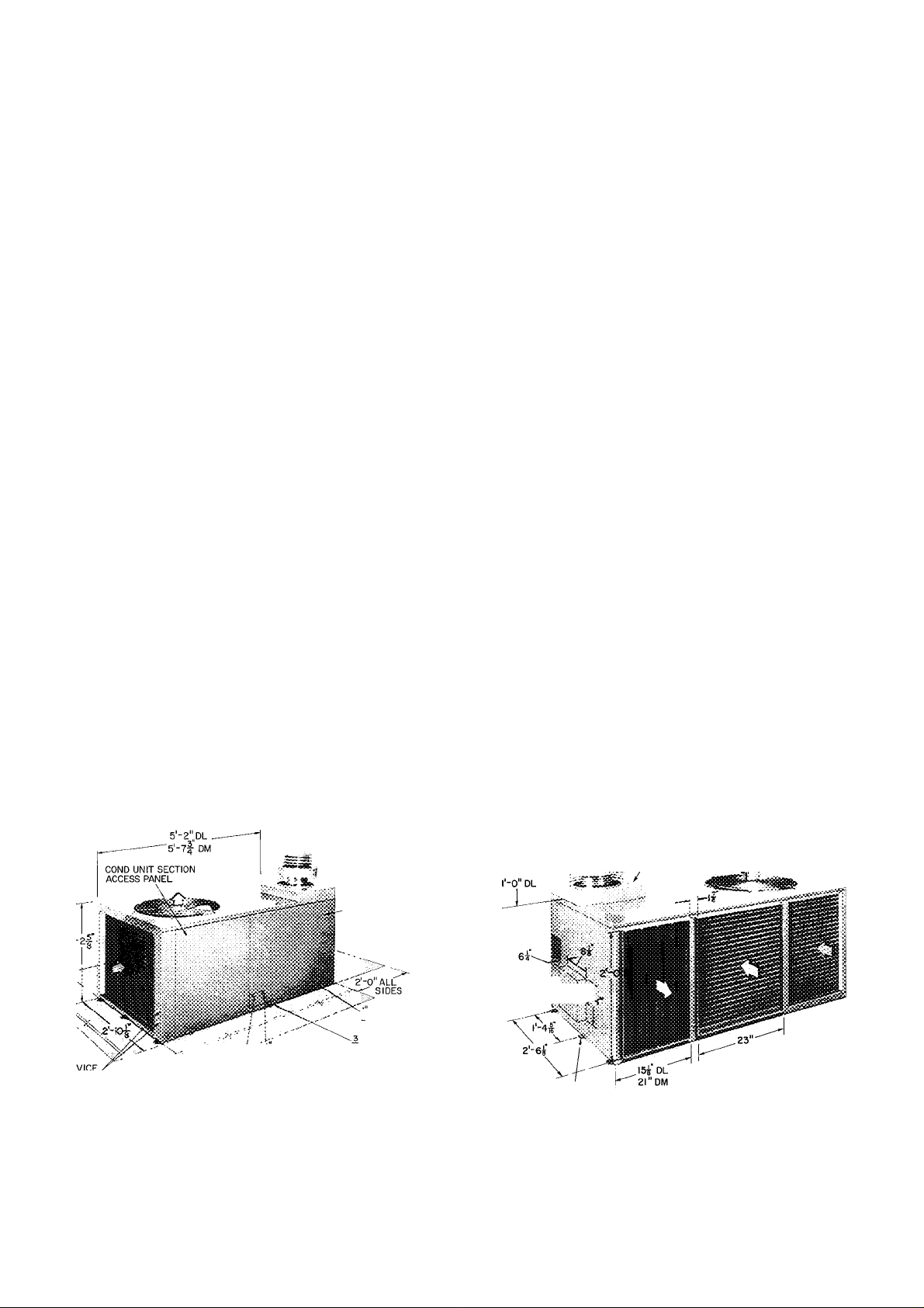
Table 1 — Physical Data
UNIT MODEL
OPERATil^ WEIGHT (lb)
REFRIG (22) CHGIIb-oz)
COMPRESSOR
Cylinders
Rpm (60-Hz)
CONDENSER FAN
Air Quantity (Cfm)
Motor Hp
evaporator fan
Size (in.)
Nominal Cfm
Rpm Range
Max Allowable Rpm
Fan Pulley Pitch Diameter (in.)
Motor Pulley Pitch Diameter (in.)
Belt
Speed Change per Full Turn of
Moveable Pulley Flange (Rpm)
Factory Setting — Full Turns Open
Motor Hp
CAPACITY (1000 Btuh)
Cooling
Heating Input/Bonnet*
MAX EXTERNAL STATIC PRESSURE
Heating (in. W.C.)
FILTERSt (1-in. thick)
Disposable — No. ...Size (in.)
Permanent^ — No. ...Size (in.)
HEAT TEMPERATURE RISE (F)
GAS CONNECTION (in.)
48EL006
48EM006
" soi
"^5”5
GB30K
___
010
2
3500
Propeller Type, Direct Drive; Vertical Discharge
2700
1/3
Centrifugal, Belt Drive: Horizontal Discharge
10x9
1900
820-1250
1500
80
1 9-2 9
4L40
90
2
3/4
58
110/82 5
150/112 5
2 16x20
2 16x20
45-75
1/2
’537'
5 5
58
1 20x25
1 25x25
1 20x25
1 25x25
^Ratings shown for elevations up to 2000 ft above sea level For elevations above 2000 ft deduct 4% capacity for each
1000 ft above sea level
fRecommended field-supplied filter
JBased on 0 055 in wg pressure drop or less thru filter
WIND CAP 4‘-0"OVERHEAD SPACE
COMBUSTION AIR REQUIRED FOR SERVICE
INLET BOX yTv AND AIRFLOW
2-0 \
ALL SIDES
li- DIAM HOLE FOR
i DIAM HOLE FOR
CONTROL WIRING
LINE POWER
WIRING
EVAPORATOR AND
HEATING SECTION
ACCESS PANEL
i- FPT GAS
VALVE CONN
CONDENSATE
’ DRAIN CONN
r-oi DM
SUPPLY GAS I:.; .
CONN HOLE^'
|DIAM(6MTG HOLES)
I
О INDOOR AIR
Ф CONDENSER AIR
Certified dimension drawings available on request
I
Space required for service Design certified by A G A for installation on
combustible-type floor with minimum space of 2'-0" on all sides
Fig. 1 — Physical Data and Dimensions
Page 3
Ductwork Installation — For air duct system design
information, refer to Carrier System Design
Manual, Part 2. System airflow must be within the
range of temperature rise and external static
pressure shown on the unit A.G.A. rating plate.
Bolt or screw ductwork to unit supply and
return air duct flanges and seal joints with sheet
metal flashing. Flange location and dimensions are
given in Fig. 1. Use flexible connectors between
ductwork and unit to dampen vibration. If a single
split duct is connected to the unit, use a gasket to
prevent air bypass between supply and return sides.
Insulate and weatherproof all external duct
work. Secure ducts to building structure and
weatherproof all duct openings in wall or roof.
Ducts passing thru unconditioned spaces must be
insulated and provided with a vapor barrier.
Filter Installation (Field-Supplied)
1. Locate filter in return air system. Convenient
location for filter is inside building behind
return air grille. Size and number of required
filters is given in Table 1.
2. Attach filter manufacturer’s instructions to
filter rack.
ASSEMBLE WIND CAP AND
COMBUSTION-AIR INLET BOX
WIND CAP
ASSSMSi-Y
auEPiPc
(PARTOF WiNOCAP
ASS£M8LY)
EY£L£TS(3)
« yHSATrSHfEXP
‘^^COLtAR
COMBUSTfON
AiR inlet BOX
RETAININS
CUP
TOP COVER
OF UNIT
!
TCP COVER
EXTRUSION
FLUE BOX
EXTRUSION
HEATING SECTION
ACCESS PANEL
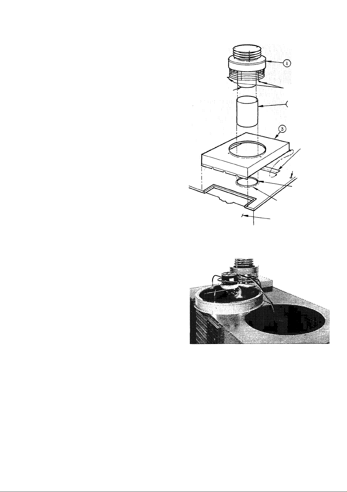
Fig. 2 — Wind Cap and Air Inlet Box Assembly
Locate — The wind cap assembly, heat-shield collar
and combustion-air inlet box (items 1, 2 and 3 of
Fig. 2) are shipped within the condenser section
except 460 volt units.
On 460 volt units, only the combustion-air inlet
box is shipped within the condenser section. The
heat-shield collar and wind cap assembly are
shipped in a separate package.
Remove 6 sheet metal screws and lift condenser
fan, grille and orifice from the top of the con
denser section (Fig. 3). Remove and discard metal
banding securing the wind cap and/or inlet box and
remove the item(s) from the condenser section.
Before replacing the condenser fan, grille and
orifice, remove any shipping tape from the con
denser fan.
Assemble (Fig. 2)
1. Mount the combustion-air inlet box (item 3) by
sliding the horizontal box flange under the
retaining clip on the unit top cover. Fasten the
inlet box with sheet metal screws provided.
2. Place end of heat-shield collar and secure wind
cap assembly (item 1 ) with 3 sheet metal screws
thru wire cage eyelets.
PIPING AND WIRING
Gas Piping — Install piping per national and local
codes and ANSIZ223.1 entitled “National Fuel
Gas Code,” (published by American Gas Asso-
Fig. 3 — Removing Condenser Fan
and Orifice Assembly
ciation, 1515 Wilson Blvd., Arlington (Rosslyn),
VA 22209).
1. Furnish the gas line from the main gas supply
to the unit gas valve (Fig. 4). Connection at gas
valve is 1 /2 in. FPT.
2. Size the supply pipe for 0.3-in. wg maximum
pressure drop and for the volume of gas
required (Tables 2, 4 and 5). Pipe size must
equal or exceed size of gas connection at unit.
3. Use pipe dope approved for use with liquefied
petroleum (LP) gases.
Page 4
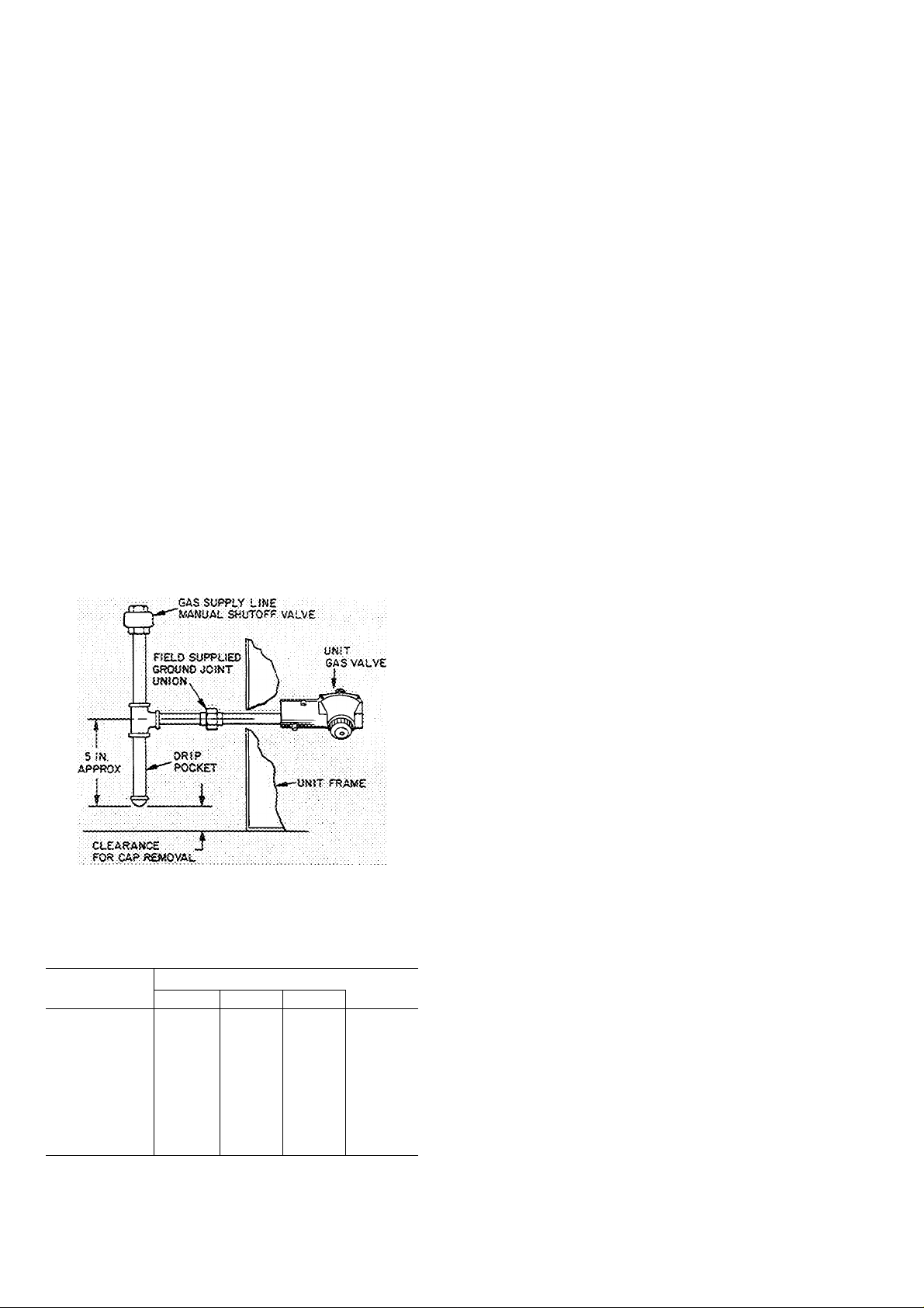
Pitch all horizontal pipe runs towards the unit
1 /4-in. per 15 ft to prevent trapping condensed
moisture.
5.
Support piping to maintain proper pitch,
prevent strain on unit controls, and prevent
accidental movement of piping.
Install a tee for attachment of a dirt and
moisture drip pocket (Fig. 4). Tee should be at
same level or below gas valve connection. Drip
pocket must be protected against freeze-up
7.
Install manual shutoff valve on gas piping per
local codes.
8. Provide a ground joint union in the gas supply
line near the unit gas valve.
9. Protect gas piping from freezing temperatures
Gas stoppage can result from failure to insulate
pipe against wide or sudden temperature
changes.
10. When piping is completed, check entire gas
assembly and field piping with soap and water
solution.
Never use an open flame for leak testing.
NOTE Connection to unit gas valve is 1/2 in FPT
Fig. 4 — Gas Piping Details
Table 2 — Maximum Pipe Cap. (cfh)*
PIPE
LENGTH (ft)
10
20
30 73
40
50
60
70
80
90
100
*Cfh — Cu ft/hr based on 0 3 in wg pressure drop and 0.6
gas specific gravity
NOTE: Correction is not necessary for normal number of
fittings nor for 0.7 gas specific gravity unless specified
NOMINAL PIPE SIZE (in.)
1/2
132 278 520
92 190 350
63
56 115
—
—
—
—
—
3/4
152
130
105 195
96 180
90
84
79
1 1-1/4
285 590
245 500
215 440
170 350
160 320
150 305
1050
730
400
370
Drain Piping — The condensate drain connection
(3/4-in. MPT) is on service access face of unit
(Fig. 1). Since drain is on the suction side of the
indoor (evaporator) fan, it must be trapped to
prevent leakage back into the unit. Trap should be
at least 3 in. deep and should be formed of flexible
material or in such a manner as to resist freeze-up
damage.
Wiring — The design center voltage for each unit is
stamped on the unit nameplate. The supply voltage
at the unit must be within maximum and minimum
limits shown on nameplate and in Tabled. Phase
unbalance on 3-phase units must be within 2%.
Contact local power company if correction is
necessary. Operation of the unit on improper line
voltage or with excessive phase unbalance is con
sidered abuse and is not covered by Carrier warranty.
Provide a branch circuit fused disconnect of
adequate size to handle unit starting current
(Table 3). Disconnect must be within sight of and
readily accessible from the unit in accordance with
Section 440-14 of the National Electrical Code
(NEC). Provision for locking switch at open (off)
position is advisable to prevent power from being
turned on while unit is being serviced.
Use only UL approved copper or copper-clad
aluminum power wires.
UNIT CONNECTION
1. Attach field power conduit to 1-1/8 in. hole at
front of high voltage (line wiring) junction box
(Fig. 1).
2. Run conduit so that access panels can be
readily removed.
3. Splice field power wires to the pigtail leads in
the junction box. Wire nuts are provided for
either copper or aluminum wire. These must be
field insulated.
4. Route the control-voltage field wiring thru the
7/8-in. hole in low-voltage junction box
(Fig. 1). If conduit is not used, protect wires by
inserting diaphragm grommet into the hole.
Make all connections to pigtail leads, but do
not use aluminum control wire for splice
connection to the copper pigtails.
Accessory Installation and Wiring
REMOTE CONTROL CENTER - The installation
instructions for this combination heating-cooling
thermostat and subbase are included with the
accessory.
Locate the thermostat on an inside wall or
column where it is affected only by the average
temperature of the room. The subbase has slots for
direct mounting on wall or on vertical outlet box.
Run the thermostat cable or equivalent single
leads of no. 18 colored wire from subbase ter
minals to 7/8-in. diameter hole in access side of
unit (Fig. 1) and attach to low voltage (control
wiring) terminals in junction box (Fig. 5).
Page 5

Table 3 — Electrical Data (60-Hz)
GE
230/1/60
460/3/60
VOLTA
Min-Max
207-264
187-253 22 7 132
414-528
UNIT MODEL
Norn V/Ph/Hz
48EL,EM006300,310
48EL,EM006500,510 208-230/3/60
49EL,EM006600,610
FLA — Full Load Amps LRA — Locked Rotor Amps
Table 4 — Gas Data — 48EL,EM006
TYPE
OF PER
GAS
Natural
Butane
Propane
Propane
BTU
CU FT
1000
1050
1100
3200
2500
2500
SPECIFIC
GRAVITY
60
65
60
60
_65^
2 00
1 53
1 53
Ml PR
CO
RLA
35 3 175
10.4
LRA
66 28
RLA — Rated Load Amps
MANIFOLD MAIN
PRESSURE BURNER
(in. wg) ORIFICE
3.3
3.5
30
3.2
27
2.9
12.2
OUTDOOR
FAN
MOTOR
FLA
2.8
28
_
108
INDOOR
FAN
MOTOR
FLA
6 9 55
6 9 40
6 9 20
#41 Drill
#54 Drill
#53 Drill
POWIEI
Min
Ckt
Amp
ORIFICE
.023 in
3 SUPPLY
Max
Fuse
Amps
70
50
25
PILOT
009 in
.009 in
THE RMOSTAT C OMBINA TIONS F OR ALL UNIT S
1 HH07AT0 74 A ND SUB BAS E HH 93A Z076
2 HH0IAD0 42 A ND SUBBASE HH 93A Z042
3 H H0IA D04 0 AN D S UBB ASE HH93AZ 040
I I I I I
I
BRN I BLK
I
RED BL U ORN
I 1
I I I I I
È * é I [È '
^ ^ FIELD POWER
FIELD CO NTR OL
WIR ES
I I Thermostat Connections
_$^Splice Connection
*Not connected when single-phase power input is used.
------------------
WIR ES
----------
BLU —
— B LK -
-YE L^
Field Power Wiring
Field Control Wiring
Factory Wiring
Fig. 5 — Remote Control Wiring
for Thermostat Combinations
When thermostat wiring is complete, mount
thermostat to subbase per instructions included
with the control. Do not turn on unit power at this
time; refer to Start-Up section of this publication.
Thermostat heat anticipator setting is 0.6 amps.
REMOVE SHIPPING TAPE on condenser fan, if
not previously removed.
CHECK COMPRESSOR HOLD-DOWN BOLTS -
Compressor is internally spring-mounted. Do not
loosen or remove hold-down bolts.
SET HEAT ANTICIPATOR on thermostat at 0.6
amps.
OPEN GAS SUPPLY LINE VALVE and purge line
by loosening ground joint union (Fig. 4). Tighten
union when gas odor is detected.
ADJUST BLOWER SPEED, if required, to main
tain heat temperature rise limits given in Table 1.
CHECK MAIN BURNERS
1. Measure and adjust main burner gas input as
described in Service section.
2. Turn main gas valve to ON position and operate
unit for at least 15 minutes with all access
panels in place.
3. With unit operating, remove heating section
access panel. Check burner flames. Flames
should be clear, almost transparent blue. If
flames appear yellow, a change to factory set
primary air adjustment has occurred. Refer to
Fig. 7 and readjust primary air as follows:
Loosen primary air spoiler locking screw.
Rotate adjustment tab counterclockwise
(slightly) until flame becomes blue. If flames
lift off burner ports, turn adjustment tab
clockwise. Retighten locking screw.
FINAL HEATING SYSTEM CHECKOUT - Move
thermostat dial above and below room temperature
setting several times, pausing at least 5 minutes
between cycles. Check pilot flame, main burner
ignition, flame characteristics and indoor (evap
orator) fan motor time delay relay operation.
Replace heating section access panel.
COOLING SYSTEM CHECKOUT
1. Turn power on.
Page 6

2. Set room thermostat selector switch at COOL
or AUTO, and dial setting below room
temperature.
3. Move thermostat dial above and below room
temperature several times, pausing at least 5
minutes between cycles. Check fan and com
pressor operation.
PILOT ADJUSTING SCREW CAP
MANUAL SHUTOFF VALVE
AND PILOT COCK
LOW VOLTAGE
CONNECTIONS
REGULATOR ADJUSTING
COVER (ADJUST Hi"
SIDE SCREW)
PILOT GAS LINE
CONNECTION
MAIN GAS CONNECTION
PRESSURE TAP
------------------
2. Set thermostat selector switch at HEAT posi
tion and set thermostat dial a few degrees above
room temperature.
3. Turn power on, and unit automatically operates
as described below.
AUTOMATIC SEQUENCE
1. Pilot valve opens, spark ignition and indoor fan
time delay relay energize.
2. Gas flows to pilot and ignites. Pilot flame
sensing probe permits energizing of the main
gas valve. Gas flows to main burner and ignites.
3. Time delay relay starts indoor fan motor in 30
— 45 seconds.
4. When thermostat setting is satisfied, main gas
valve and pilot gas valve close and flames are
extinguished.
5. Indoor fan motor stops in I - to 1-1/2 minutes.
CAUTION; l>o not use matches to li^t
pilof on iniennitient pilot units because of
electrical shock hazard-
Fig. 6 — Unit Gas Valve
AIR/GAS MIXTURE
ADJUSTMENT TAB
LOCKING SCREW
-.33
^^.^eCTROOE
:«LOr SOOT
¡¡—T
LOCKING SCREW' ^
Fig. 7 — Main Burner Adjustment Details
Start-Up Sequence, Natural and LP Gas Units With
Intermittent Spark Ignition of Pilot, indoor (evap
orator) fan motor time delay relay and Essex
SX242 gas valve.
MANUAL SEQUENCE
1. With power off turn manual gas valve knob to
ON position.
GENERAL OPERATING SEQUENCES
These sequences apply to both natural and EP gas
units in normal operation after initial start-up.
Operating Sequence-Heating
NATURAE GAS AND LP UNITS WITH INTER
MITTENT PILOT
1. Thermostat selector switch at HEAT or AUTO.
Thermostat dial set above room temperature.
2. Pilot gas valve opens. Gas flows to pilot and
ignites. Pilot flame sensing probe causes main
gas valve to open. Gas flows to main burner and
ignites.
3. TDR starts indoor fan motor in 30 — 45
seconds.
4. When thermostat is satisfied both pilot gas and
main gas valves close. Pilot and main burner
flames are extinguished.
5. TDR stops indoor fan motor in 1- to 1-1/2
minutes.
6. Pilot is on only when thermostat calls for
heating.
Operating Sequence — Cooling
1. Unit energized. Thermostat selector switch at
COOL or AUTO. Thermostat dial set below
room temperature.
2. Indoor and outdoor fans and compressor start.
3. When thermostat setting is satisfied, fans and
compressor stop.
Automatic Operation — Power and gas on. Room
thermostat (control center) set at AUTO. Fan
switch (on control center) set at AUTO.
Unit performs as described in the operating
sequences above on call for heating or cooling.
Page 7

Automatic changeover type thermostat is required.
Continuous Fan Operation — With power supplied
to unit and fan switch at ON position, indoor fan
remains on at all times.
Complete Shutdown or Change from Heating to
Cooling
1. Turn thermostat selector switch to OFF.
2. Remove heating section access panel.
3. Turn manual shutoff valve (Fig. 6) to PILOT.
Then depress valve and turn to OFF.
4. Turn off power. Replace access panel.
SERVICE
Adjusting Main Burner Gas Input (Refer to Fig. 4
and 6 and to Table 4 and 5) -- Need for adjustment
is determined by comparing measured gas input
(flow rate or manifold pressure) against the rated
input of a gas with a specific heating value. Check
local gas supplier for correct heating value (BTU’s
per cu ft). Before measuring, shut down all other
gas appliances.
Flow rate (cfm), the most accurate method, is
measured by gas meter and stop watch. Check
measured flow against rated flow in Table 5.
Refrigerant Charging — Standard 1/4-in. Schrader
service connections are provided on the high and
low sides of the refrigerant system for charging and
evacuation.
Amount of refrigerant charge is listed on unit
nameplate (also refer to Table 1). Refer to Carrier
Standard Service Techniques Manual, Chapter 1,
Refrigerants.
Unit panels must be in place when unit is
operating during charging procedure.
NO CHARGE — Use standard evacuating tech
niques. After evacuating system, weigh in the
specified amount of refrigerant.
LOW CHARGE — Using charging chart (Fig. 8),
add refrigerant until the conditions of the chart
are met. Charts are based on charging the units to
the correct superheat for the various operating
conditions. An accurate pressure gage and tem
perature sensing device are required. Connect the
pressure gage to the service port on the suction
line. Mount the temperature sensing device on the
suction line and insulate it so that outdoor
ambient temperature does not affect the reading.
Indoor air cfm must be within the normal
operating range of the unit.
^ Table 5 — Gas Rate (cfm)
UNIT
Natural 1000 1 83 2 50
Natural 1050 1 74 2 38
Natural 1100 1 66 2 27
Butane 3200 57
Propane 2500 73 1 00
48EL006 48EM006
78
Manifold pressure (in. wg) is measured as
follows:
1. Remove heating section access panel.
Shut down unit and close gas supply line valve
2.
(Fig. 4).
Remove pressure tap plug from main gas valve
3.
(Fig. 6) and install pressure tap.
4.
Attach U-tube water gage manometer to pres
sure tap and open gas supply line valve.
Start-iip heating system.
5.
6.
Measure gas pressure (in. wg) and compare with
rated pressure in Table 4.
To adjust pressure or flow rate:
1. Remove pressure regulator adjusting screw cap
on main gas valve (Fig. 6).
Turn screw slowly, clockwise to increase pres
2.
sure (flow), and counterclockwise to decrease.
Replace adjusting screw cap.
3.
4.
Shut down heating system.
Close gas supply line valve, remove manometer
5.
and replace pressure tap plug.
Open gas supply line valve and replace heating
6.
section access panel.
SUCTION LINE TEMPF
Fig. 8 — Charging Chart — 48EL,EM006
TO USE CHARGING CHART - Take the outdoor
ambient temperature and read the suction pressure
gage. Refer to chart to determine what the suction
temperature should be. If the suction temperature
is high, add refrigerant. If the suction temperature
is low, carefully blow some of the charge. Recheck
the suction pressure as charge is adjusted.
If Chargemaster® charging device is used, tem
perature and pressure readings must be accom
plished using charging chart. Fig. 8.
Page 8

Part Removal (Refrigerant System)
CAUTION: System contains oil and refiigerant
under pressure. Do not use torch to remove
component. Wear your protective gog^es.
1. Shut off electrical power to unit.
2. Relieve all pressure from system.
3. Cut connecting piping with tubing cutter.
4. Remove component from unit.
5. Unsweat piping stubs carefully. Oil may ignite
when exposed to torch flame.
WELDED HERMETIC COMPRESSOR - Make
certain that all safety codes are followed. Use
protective goggles, work gloves and water-soaked
quenching cloth.
1. Shut off electrical power and remove all wiring
from compressor.
2. Purge or remove all refrigerant and pressure
from system.
3. Cut suction and discharge lines with tubing
cutter at convenient place near compressor to
facilitate reassembly with copper slip
couplings.
4. Remove compressor from unit and carefully
unbraze piping stubs. Oil vapor in piping stubs
can ignite from torch flame, use quenching
cloth if necessary
5. Install old piping stubs on new compressor and
carefully braze in place.
6. Clean system. Add or replace liquid line filter
drier.
7. Install hew compressor in unit and braze in
place with field-supplied copper slip couplings.
Protect pressure relief plug in suction line with
wet rag if brazing near it.
8. Connect wiring; replace wire terminals if
necessary.
9. Attach caution sticker to new compressor.
10. Proceed with evacuation, charging and start
up. Procedures for evacuation and system
cleanout can be found in Carrier Standard
Service Techniques Manual, Chapter 1, Form
SM-1.
Part Removal Evaporator Fan (Blower Wheel) —
Remove fan as follows:
1. Shut off all electrical power to unit.
2. Remove heating section access panel.
3. Loosen 5 screws and remove interior panel.
4. Disconnect the 2 wires to the fan motor.
5. Remove screws holding the evaporator fan
housing and the support strap and slide housing
and fan from unit.
Spring Inspection
Disconnect electrical power before working
inside unit.
1. Inspect and clean (if required) fan blades and
housing, cooling coil, condensate pan and drain.
See below for cleaning details.
2. Inspect and clean air filter, and supply and
return air grilles.
3. Check electrical components and connections.
Checking procedures may be found in Carrier
Standard Service Techniques Manual,
Chapter 2, Form SM-2.
4. Inspect panels and ducts for air leaks.
Fall Inspection
Disconnect electrical power before working
inside unit.
1. Follow all steps under Spring Inspection.
2. Inspect and clean pilot, main burners, heat
exchangers and flues.
3. Check main gas valve operation.
Cleaning
HEAT EXCHANGER
1. Shut down unit.
2. Remove heating section access panel, heat
shield front upper panel, flue box and radiation
baffle over burners. Preserve all gaskets.
3. Clean soot from inside of heat exchanger and
other internal surfaces, especially the narrow
vertical sections of tubes. Use a long wire-
handled nylon-bristle brush and vacuum
cleaner.
4. Reassemble unit. Take care not to damage
gaskets.
INDOOR (EVAPORATOR) COIL - Clean with
stiff brush, vacuum cleaner or compressed air.
OUTDOOR (CONDENSER) COIL - Clean out
door coil annually or as required by location or
• outdoor air conditions. Inspect coil monthly —
clean as required.
Fins are not continuous thru coil sections. Dirt
and debris may pass thru first section, become
trapped between the 3 rows of fins, and restrict
condenser airflow. Use a flashlight to determine if
dirt or debris has collected between coil sections.
Clean coil as follows"
1. Turn off unit power.
2. Remove top cover screws and slide cover
toward the compressor end of unit and/or to
the side to expose top of condenser coil.
3. Remove screws that fasten the 3 sections of the
tube sheet together at the return bend end of
the condenser coil. Carefully spread the ends of
the coils apart (see Fig. 9).
Page 9

#
Fig. 9 — Outdoor Coil Cleaning
Using a water hose, or other suitable equip
4.
ment, flush down between the 3 sections of the
condenser coil to remove dirt and debris.
Clean the remaining surfaces in the normal
5.
manner.
Reposition the inner coil sections. Reinstall the
6
screws in the tube sheet and replace the top
cover.
CONDENSATE PAN AND DRAIN LINES - Clean
once a year, preferably in the spring. Drain off
water in the fall and keep trap dry or protect from
freeze-up thru the winter.
FILTERS — Inspect filters at start of each heating
and cooling season and as often during each season
as conditions warrant. Clean permanent filters per
manufacturer’s instructions. Throwaway filters
may be cleaned by vacuum or by tapping lightly
over newspaper. Replace filters with the cleaner
side facing downstream. After one cleaning, replace
throwaway filter.
INDOOR FAN ADJUSTMENT - Fan motor
pulley is factory set for speed shown in Table 1. To
change fan speed:
1. Shut off unit power supply.
2.
Slide fan housing from unit.
3.
Loosen fan belt by loosening fan motor
mounting plate bolts.
4.
Loosen movable pulley flange setscrew (see
Fig. 10).
5.
Screw movable flange toward fixed flange to
increase speed and away from fixed flange to
decrease speed. Increasing fan speed increases
load on motor. Do not exceed maximum fan as
specified in Table 1.
6.
Set movable flange at nearest key way of pulley
hub and tighten setscrew.
To align fan and motor pulleys, loosen fan
pulley setscrews and slide fan pulley along fan
shaft. Make angular alignment by loosening motor
from mounting plate (see Fig. 10).
Fig. 10
To Adjust Belt Tension — Loosen fan motor pivot
bolts. Move motor mounting plate for proper belt
tension (1/2-in. deflection with one finger) and
tighten pivot bolts. Adjust lock bolt and nut on
mounting plate to secure in fixed position.
OUTDOOR FAN ADJUSTMENT ^ The required
fan position is shown in Fig. 11. Loosen setscrews,
set fan at dimension indicated and retighten.
Adjusting Spark Ignition — If pilot fails to ignite,
check the spark ignition system as follows:
1. Shut off power to ignitor.
2. Check that spark gap is .12 inch. (See Fig. 7.)
3. Make sure that spark generator is .securely
grounded.
4. Check that high-voltage lead is securely con
nected between generator and electrode body.
5. Restore power. Check for 24-volt supply to
primary side of generator.
Indoor Air Fan Pulley Alignment
and Adjustment
Fig. 11 — Outdoor Fan Clearance
Page 10

Lubrication
FAN MOTOR BEARINGS are factory lubricated
and do not require service for 3 to 5 years,
depending upon type of service. When required,
clean and relubricate per motor manufacturer’s
instructions.
COMPRESSOR contains a factory oil charge. If oil
is lost thru leakage, refer to Carrier Standard
Service Techniques Manual SM-1, Chapter 1 for oil
recharging procedure.
TROUBLESHOOTING - HEATING SYSTEM
Burner Does Not Operate
Power failure — Power switch off; blown line
fuse; defective wiring. .
No power to controls — thermostat set too low,
dirty or defective; defective transformer, faulty
limit switch.
Burner does not ignite — no gas to unit; faulty
valve or pilot switch; faulty spark ignitor; dirty
pilot.
Burner Operates, But Heating is Inadequate
Unit undersized — unit size selected incorrectly
Fuel input too low ~ wrong orifice size,
regulator set too low
Thermostat opens too soon ~ wrong antici
pator setting, thermostat out of calibration,
wrong thermostat location; thermostat set
wrong.
Limit switch cycles burner
faulty fan switch or motor;
wrong; duct system restricted
Poor Combustion and Flame Characteristics
Smoky flame — insufficient air, flue restriction.
Noisy burner — too much air, incorrect input
TROUBLESHOOTING - COOLING SYSTEM
Compressor Does Not Start
Power failure — power switch off; blown line
fuse, defective wiring.
No power to controls ~ thermostat set too low;
or dirty or defective, defective transformer.
— dirty filters;
limit switch set
contactor coil open; loose leads from closed
contactor.
Power to compressor — motor windings open,
contactor closes, then opens
Compressor Runs But Cooling is Insufficient
Low suction pressure — restricted airflow;
capillary tubes restricted; low refrigerant
charge.
Low head and high suction pressure — defective
compressor valves.
Indoor fan stopped — loose or broken leads,
faulty capacitor; internal short circuit
Compressor Does Not Restart
Power failure — power switch off, blown line
fuse
Power at closed contactor — faulty start relay
or capacitor, contactor, run capacitor or com
pressor, low line voltage (must be within 10%
of nameplate voltage )
Compressor Cycles on Overload
Insufficient condenser air — check condenser
fan position in reference to orifice as in Fig 11.
Condenser air restricted ^ dirty coil, airflow
restricted
Condenser air recirculating — obstruction de
flecting airflow.
Improper line voltage — circuit overloaded;
loose electrical connections
Faulty run capacitor — capacitor shorted or low
on capacitance (mfd)
Noncondensables in system — moisture or air in
system
System overcharged — high head pressure
causes by excessive refrigerant.
No refrigerant in system — leak in system.
System restricted — capillary tubes restricted or
plugged, kinked tubing, dirty strainer
Fan slipping on motor shaft — setscrews either
loose or missing from fan.
Fan motor bearing seized — lack of oil or
bearing failure.
Fan motor defective — internal short circuit
Page 11

For replacement items use Carrier Specified Parts.
Manufacturer reserves the right to discontinue, or change at any time, specifications or designs without notice and without incurring obligations.
Book
Tab
1 4
1a
6a
Form48EL-1SI Supersedes48DL-1SI
Printed in U S A 11-78
PC 111
Catalog No 534-853
 Loading...