

Carrier 42BHE10, 42BHE12, 42BHE16, 42BHE20, 42BHE30 Installation, Start-up And Service Instructions Manual
...Page 1
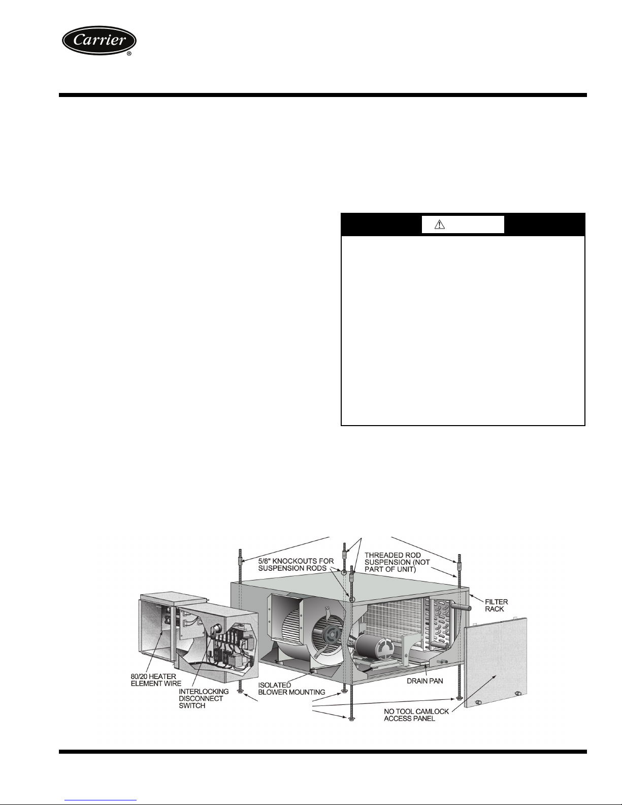
ISOLATORS
(FIELD FURNISHED AND INSTALLED)
WASHER AND
DOUBLE NUT
(FIELD FURNISHED
AND INSTALLED)
Fig. 1 — Component Identification (42BHE Units Shown)
A42-4258
AIRSTREAM™
42BHE,BVE06-40
System Fan Coil Air Conditioners
Installation, Start-Up and Service Instructions
CONTENTS
Page
SAFETY CONSIDERATIONS . . . . . . . . . . . . . . . . . . . . . . 1
INTRODUCTION . . . . . . . . . . . . . . . . . . . . . . . . . . . . . . . . . . 2
INSTALLATION . . . . . . . . . . . . . . . . . . . . . . . . . . . . . . . . . 2-6
Step 1 — Unpack and Inspect Unit . . . . . . . . . . . . . . . 2
Step 2 — Protect Unit from Damage . . . . . . . . . . . . . . 2
Step 3 — Prepare Jobsite . . . . . . . . . . . . . . . . . . . . . . . . 2
Step 4 — Prepare Unit. . . . . . . . . . . . . . . . . . . . . . . . . . . . 3
Step 5 — Position Unit . . . . . . . . . . . . . . . . . . . . . . . . . . . 3
Step 6 — Make Piping Connections . . . . . . . . . . . . . . 4
Step 7 — Make Electrical Connections . . . . . . . . . . . 5
Step 8 — Make Duct Connections . . . . . . . . . . . . . . . . 6
Step 9 — Install Mixing Box . . . . . . . . . . . . . . . . . . . . . . 6
Step 10 — Make Final Preparations . . . . . . . . . . . . . . 6
START-UP . . . . . . . . . . . . . . . . . . . . . . . . . . . . . . . . . . . . . . . . 7
Air System Balancing . . . . . . . . . . . . . . . . . . . . . . . . . . . . 7
SERVICE . . . . . . . . . . . . . . . . . . . . . . . . . . . . . . . . . . . . . . . . 7,8
Clean Coils. . . . . . . . . . . . . . . . . . . . . . . . . . . . . . . . . . . . . . . 7
Check Drain . . . . . . . . . . . . . . . . . . . . . . . . . . . . . . . . . . . . . . 7
Fan and Motor Bearings. . . . . . . . . . . . . . . . . . . . . . . . . . 7
Align Pulley . . . . . . . . . . . . . . . . . . . . . . . . . . . . . . . . . . . . . . 7
Adjust Fan Belt Tension . . . . . . . . . . . . . . . . . . . . . . . . . . 7
Clean Fan Wheel . . . . . . . . . . . . . . . . . . . . . . . . . . . . . . . . . 7
Clean or Replace Air Filters . . . . . . . . . . . . . . . . . . . . . . 7
Recommended Maintenance . . . . . . . . . . . . . . . . . . . 8
TROUBLESHOOTING. . . . . . . . . . . . . . . . . . . . . . . . . . . . . 8
Excessive Condensation on Fan Coil Unit Parts. . 8
Motor Overload . . . . . . . . . . . . . . . . . . . . . . . . . . . . . . . . . . 8
START-UP CHECKLIST . . . . . . . . . . . . . . . . . . . . . . CL-1
SAFETY CONSIDERATIONS
Air-handling equipment is designed to provide safe and
reliable service when operated within design specifications. To
avoid injury to personnel and damage to property or equipment, use good judgment and follow safe practices as outlined
below when installing and operating this equipment.
DANGER
NEVER REACH INTO a unit while the fan is running.
LOCK OPEN AND TAG the fan motor power disconnect
switch before working on unit. In addition, remove the
fuses and take them with you after noting this on tag.
DISCONNECT ALL POWER before attempting any
installation or service. More than one power source may be
supplied to a unit. Power to remote mounted control
devices may not be supplied through the unit.
CHECK THE WEIGHT of assembly and components to
be sure that rigging equipment can handle them safely.
NEVER PRESSURIZE a coil with a non-liquid for leak
testing. A dangerous burst may occur.
DO NOT STEAM CLEAN coils until you are sure all personnel are clear of the area.
Failure to follow these warnings will result in severe personal injury or death.
INTRODUCTION
The following contains general installation instructions for
the 42BHE,BVE fan coil units. (See Fig. 1.) Refer to the unitwiring diagram installed on the blower housing or specific
manufacturer literature for any other type of factory-mounted
controls.
Manufacturer reserves the right to discontinue, or change at any time, specifications or designs without notice and without incurring obligations.
Catalog No. 04-53420006-01 Printed in U.S.A. Form 42B-3SI Pg 1 2-11 Replaces: 42B-2SI
Page 2
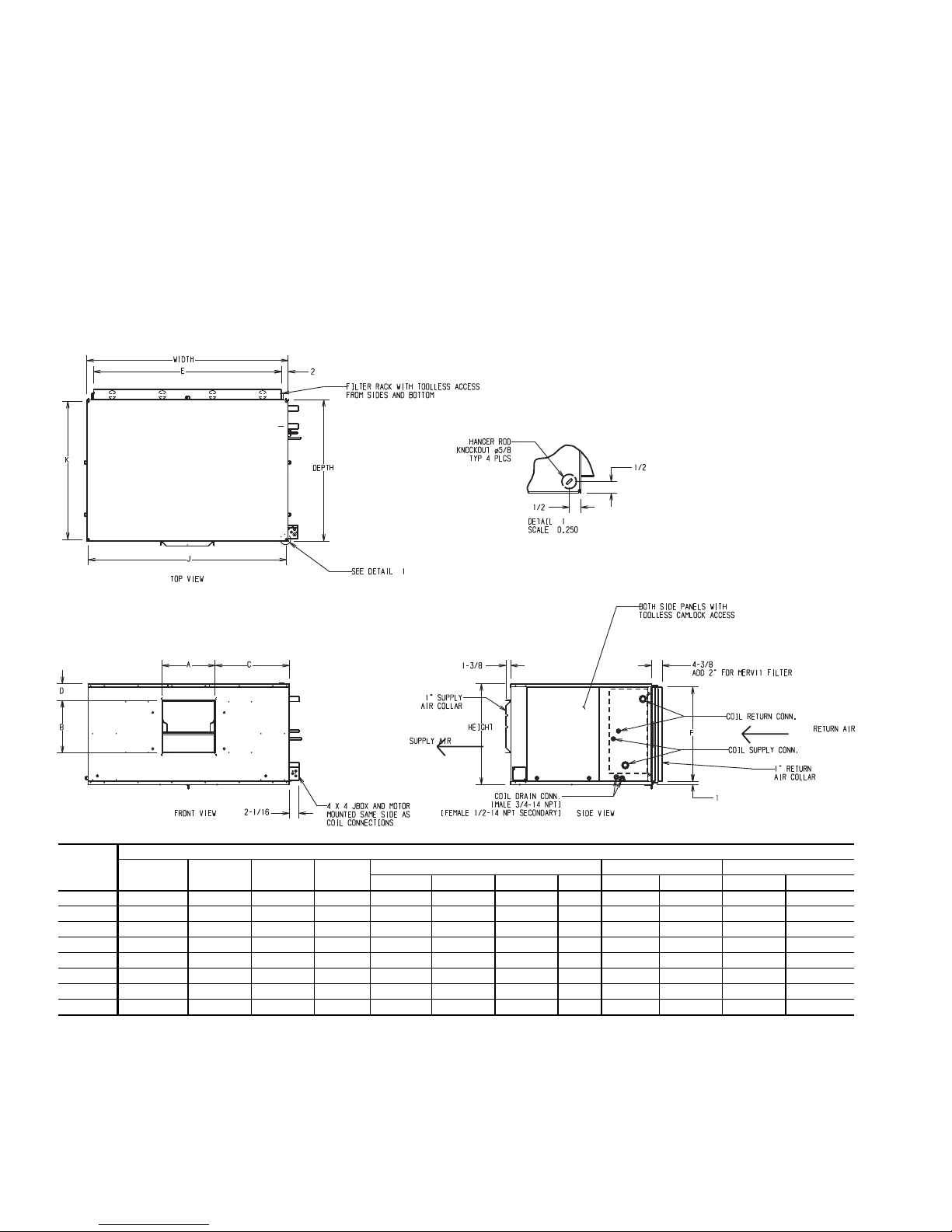
See drawings for unit configurations, dimensions, clearanc-
NOTES:
1. All dimensions are in inches (±
1
/4 in.).
2. Any modifications to product specifications by any person are subject to acceptance of the factory. Product specifications are subject to change without notice.
3. Right hand shown, left hand opposite.
4. Hanger rods, which are field supplied, are shown for reference only.
UNIT
42BHE
DIMENSIONS (in.)
Fan Size Depth Width Height
Supply Duct Return Duct Mounting Holes
ABCDEF J K
06 9 x 4 36 28 19
3
/
4
71/
8
101/
2
141/
2
21/
4
24 161/
2
271/
4
351/
4
08 9 x 6 36 28 193/
4
81/
2
101/
2
137/
8
21/
4
24 161/
2
271/
4
351/
4
10 10 x 4 371/
2
37 211/
2
71/
8
119/
16
151/
4
21/
4
33 181/
4
361/
4
37
12 10 x 7 37
1
/
2
37 211/
2
915/
16
119/
16
137/
8
21/
4
33 181/
4
361/
4
37
16 11 x 10 37
3
/
4
47 211/
2
133/
8
123/
4
163/
4
21/
4
43 181/
4
461/
4
37
20 12 x 9 40
1
/
4
48 24 121/
2
133/
4
173/
4
21/
4
44 203/
4
471/
4
391/
2
30 12 x 12 401/
4
48 321/
4
157/
8
133/
4
16 71/
4
44 29 471/
4
391/
2
40 15 x 12 431/
2
62 321/
4
167/
16
161/
16
223/
4
61/
4
58 29 613/
4
421/
2
Fig. 2 — Unit Dimensions — 42BHE Units
A42-659ef
es, and pipe connections. Refer to unit wiring label for all electrical connections. Follow NEC (National Electrical Code) and
local codes.
INSTALLATION
Step 1 — Unpack and Inspect Unit —
ping wraps from unit and check shipment against shipping list.
Check for concealed shipping damage. If shipment is damaged
or incomplete, file claim with transportation company and
contact your local Carrier representative immediately.
Remove ship-
Step 2 — Protect Unit from Damage — To main-
tain warranty, protect unit against adverse weather conditions,
theft or vandalism on the jobsite.
The described equipment IS NOT suitable for outdoor installations. The equipment should never be stored or installed
where it may be subjected to a hostile environment such as
rain, snow, or extreme temperatures.
Step 3 — Prepare Jobsite — To save time and to re-
duce the possibility of costly errors, set up a complete sample
installation in a typical room at jobsite. Check all critical dimensions such as pipe, wire and duct connection requirements.
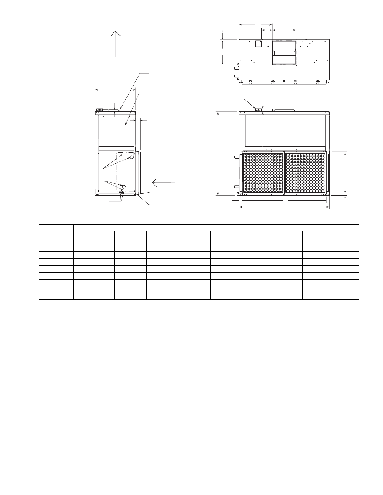
Refer to job drawings and product dimension drawings as required. Instruct all trades in the appropriate part of the installation. For unit component identification, refer to Fig. 1. For unit
dimensions, refer to Fig. 2 for 42BHE units and Fig. 3 for
42BVE units.
2
Page 3
C
A
7-7/16
TOP VIEW
2-1/16
B
4 X 4 JBOX AND MOTOR
MOUNTED SAME SIDE AS
COIL CONNECTIONS
DEPTH
1-7/16
1" SUPPLY AIR
COLLAR
SUPPLY AIR
BOTH SIDES
AND FRONT
PANEL WITH
CAMLOCK
ACCESS
4-3/8
ADD 2" FOR
MERV11 FILTER
HEIGHT
RETURN AIR
COIL RETURN CONN.
COIL SUPPLY CONN.
COIL DRAIN CONN.
[MALE 3/4-14 NPT]
[MALE 1/2-14 NPT SECONDARY]
SIDE VIEW
FILTER RACK WITH
TOOLLESS ACCESS
FROM SIDES AND TOP
1" RETURN AIR COLLAR
2
E
WIDTH
FRONT VIEW
F
1"
Fig. 3 — Unit Dimensions — 42BVE Units
NOTES:
1. All dimensions are in inches (±
1
/4 in.).
2. Any modifications to product specifications by any person are subject to acceptance of the factory. Product specifications are subject to
change without notice.
3. Left hand shown, right hand opposite.
UNIT
42BVE
DIMENSIONS (in.)
Fan Size Depth Width Height
Supply Duct Return Duct
AB CEF
06 9 x 4 20 28 36
1
/
2
71/
8
101/
2
171/
4
24 161/
2
08 9 x 6 20 28 361/
2
81/
2
101/
2
153/
4
24 161/
2
10 10 x 4 22 37 393/
8
71/
8
119/
16
241/
2
33 181/
3
12 10 x 7 22 37 393/
8
915/
16
119/
16
211/
2
33 181/
3
16 11 x 10 22 47 393/
8
133/
8
123/
4
163/
4
43 181/
3
20 12 x 9 24 48 451/
8
121/
2
133/
4
173/
4
44 203/
4
30 12 x 12 28 48 543/
16
157/
8
133/
4
16 44 29
40 15 x 12 28 62 57
5
/
8
167/
16
161/
16
223/
4
58 29
a42-4259
Step 4 — Prepare Unit — Be sure that unit power re-
quirements match available power source. Refer to unit nameplate and wiring diagram. Check all tags on unit to determine if
any shipping screws are to be removed. Remove screws as
directed.
Step 5 — Position Unit
1. The air handler has 5/8-in. knockouts in each corner of the
top and bottom panels for suspension rods to pass
through. Be sure to support the unit from underneath until
mounting is complete.
2. Install vibration isolators as shown in Fig. 1. Fieldsupplied and field-installed accessories must be independently supported or suspended. It is recommended that a
trapeze suspension be used on 42BHE size 30 and 40
units. Size your trapeze to ensure that you do not block
bottom access for filter removal.
3. For units with mixing boxes, follow Step 9 for installation
instructions.
4. To ensure proper drainage and operation, be sure unit is
level. DO NOT mount the unit on a slope. The pitch of a
suspended unit can change after coil is filled; recheck
after filling. Drain pan has built-in slope to ensure proper
drainage.
5. Sufficient clearance must be maintained for service and
maintenance. Ensure that there is a minimum clearance of
24-in. on access side for motor, pulley and belt access.
Filter shall be removed from side or top of the filter rack
on vertical unit (42BVE) and side or bottom of the filter
rack on horizontal unit (42BHE). If side access to filter is
desired, the minimum clearance required is the width of
the filter rack plus 6 inches.
6. Protect unit from damage from jobsite debris. Do not
allow foreign material to fall into drain pan. Prevent dust
and debris from being deposited on motor or fan.
3
Page 4
Step 6 — Make Piping Connections (See
42BHE/BVE
UNIT
CASING
3.0
1.5
CLEAN-OUT
ALLOW A MINIMUM OF
“C” INCHES FROM BOTTOM
OF UNIT TO FINISHED FLOOR
(42BVE UNIT) OR TO FALSE
CEILING (42BHE UNIT).
C
B
A
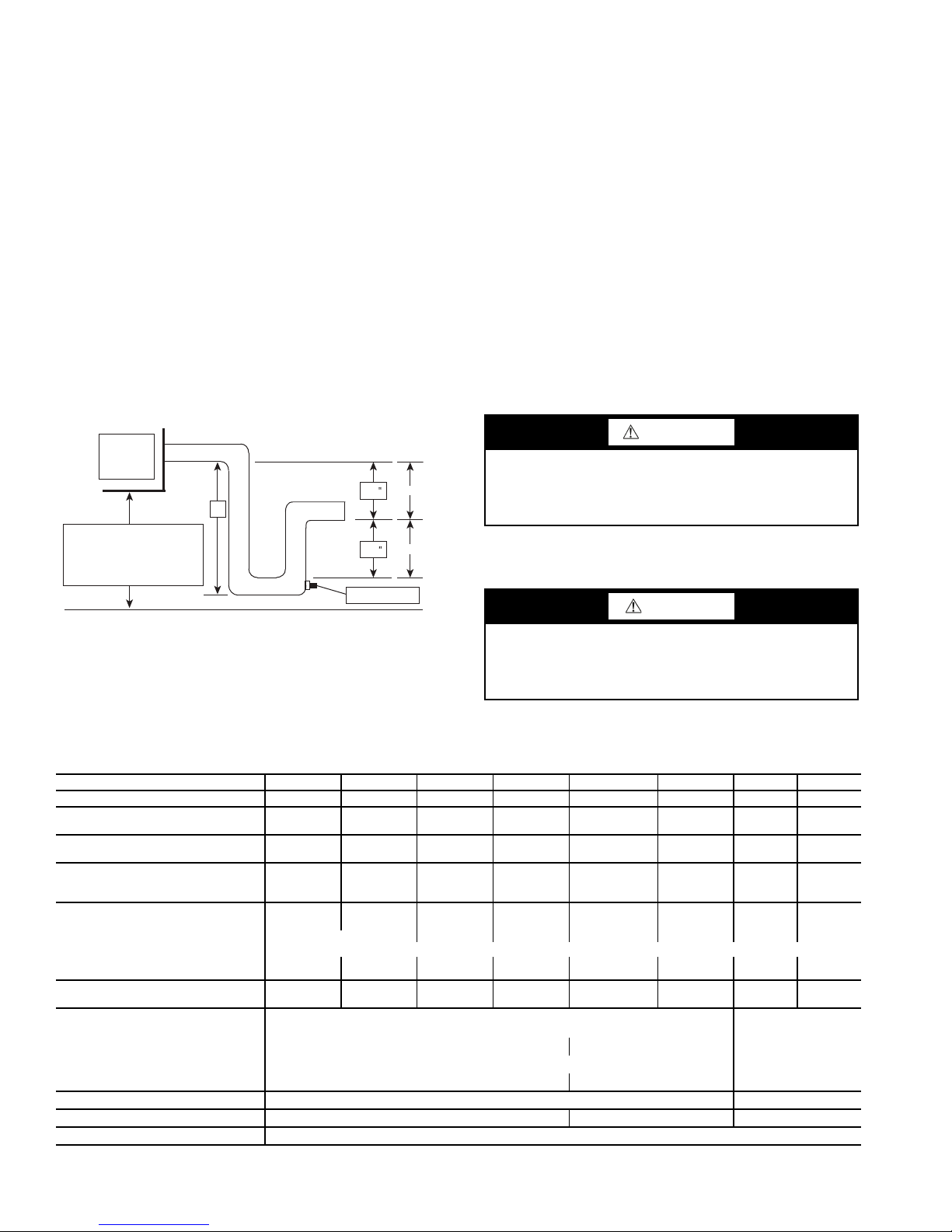
Fig. 4 — Condensate Trap
NOTE: Dimension C is the total of A + B + the pipe diameter.
Table 1 and Fig. 2 and 3)
DRAIN — The unit has a double-sloped condensate drain pan
to ensure proper drainage. The condensate drain must be at
3
least
/4-in. copper, galvanized, black iron, or PVC piping. Install the trapped drain line in accordance with all applicable
codes. Slope drain away from unit to prevent overflowing and
insulate the line to prevent sweating.
Drain piping should be sloped a minimum of
away from the unit. Condensate drain must be trapped for
proper drainage and odor control. The differential height of the
trap inlet to outlet must be at least 1-in. wg greater than the total
static pressure of the unit. The differential height of the outlet to
the bottom of the trap must not be less than the total static pressure of the unit.
The 42BVE units should be installed on a pad. The height
of the pad should be adequate to allow for a proper condensate
trap. The condensate trap shown in Fig. 4 is for a unit with a
total static pressure (TSP) of 2-in. wg with a 1-in. wg safety
factor for any change in operating conditions. The A dimension
must equal the system TSP plus 1-in. wg. The B dimension is
one half of A, and C is the total of A + B + pipe diameter.
1
/8-in. per ft
The unit drain pan is equipped with a secondary connection
that must be piped to an open-site drain. This will prevent overflow and possible building damage if the primary drain is
blocked. The secondary drain connection can be capped if potential overflow will not damage the building or unit.
WATER SUPPLY/RETURN CONNECTIONS — Install piping in accordance with all applicable codes. The supply and
return connections are marked on the coil stub ends with an “S”
on the supply (inlet) and an “R” on the return (outlet). Blue
letters mark chilled water connections, red letters indicate
steam or hot water connections. Install valves in lines in
accordance with valve manufacturer’s instructions. Be sure
valves are in proper operating position and are easily accessible
for adjustment.
HYDROSTATIC TEST — When all joints are completed,
perform hydrostatic test for leaks. Hydronic systems should be
tested with water (some components are not designed to hold
gas). If gas testing is necessary, pressure must NOT exceed
80 psig. All chilled water piping and valves not located over
drain pans or drip lips must be insulated to prevent damage
from sweating. Vent all coils during final preparations. (See
Step 10, section 6.)
WARNING
Never pressurize unit beyond the specified test pressure.
Always pressure test with an inert gas or fluid (nitrogen or
clear water) to avoid possible unit damage or personal
injury in the event of a leak during testing.
UNIT SIZE 42BHE, BVE 06 08 10 12 16 20 30 40
NOMINAL CFM 600 800 1000 1200 1600 2000 3000 4000
42BHE OPERATING WT (lb)
(no heat/ with heat)
42BVE OPERATING WT (lb)
(no heat/ with heat)
FILTERS (2 in. pleated)
Number...Size (in.) 1...161/2 x 24 1...161/2 x 24 1...181/4 x 33 1...181/4 x 33 2...181/4 x 211/22...203/4 x 22 2...29 x 22 2...29 x 29
Face Area (sq ft) 2.8 2.8 4.2 4.2 5.5 6.3 8.9 11.7
HYDRONIC COILS
Size (in.) 15 x 20 15 x 20 15 x 29 15 x 29 15 x 39 18 x 40 27 x 40 27 x 54
Face Area (sq ft) 2.1 2.1 3.0 3.0 4.1 4.9 7.7 10.3
Fins per inch
Coil Water Volume (approx. gal.
per row of coil)
FANS
Qty...Size (in.) 1...9 x 4 1...9 x 6 1...10 x 4 1...10 x 7 1...11 x 10 1...12 x 9 1...12 x 12 1...15 x 12
HYDRONIC COIL CONN. (in.)
8 ROW (Cooling) 1 nominal, 1.125 OD 1
4 AND 6 ROW (Cooling)
1 ROW (Heating)
2 ROW (Heating)
DX COIL CONN. LIQUID LINE (in.)
DX COIL CONN. SUCTION LINE (in.)
DRAIN CONN. SIZES (in.)
203/234 205/236 253/287 256/290 312/346 344/380 437/474 553/590
200/231 202/233 243/277 247/281 289/323 351/387 436/473 522/559
0.240 0.240 0.324 0.324 0.420 0.492 0.768 1.020
Check interior unit piping for signs of leakage from shipping damage or mishandling. If leaks are found, notify your lo-
cal Carrier representative before initiating any repairs.
CAUTION
All water coils must be protected from freezing after initial
filling with water. Even if system is drained, unit coils may
still hold enough water to cause damage when exposed to
temperatures below freezing.
INSULATION — Following the hydrostatic test, insulate all
piping to unit to prevent sweating.
Table 1 — Unit Physical Data
10
1
3
/4 nominal, 0.875 OD 1 nominal, 1.125 OD 11/2 nominal, 1.625 OD
1
/2 nominal, 0.625 OD 1 nominal, 1.125 OD 11/2 nominal, 1.625 OD
3
/4 nominal, 0.875 OD 1 nominal, 1.125 OD 11/2 nominal, 1.625 OD
1
/2 nominal, 0.625 OD 11/2 nominal, 1.625 OD
1
/4 nominal, 0.375 OD
3
/4 MPT
4
/2 nominal, 1.625 OD
1
/2 nominal, 0.625 OD
Page 5
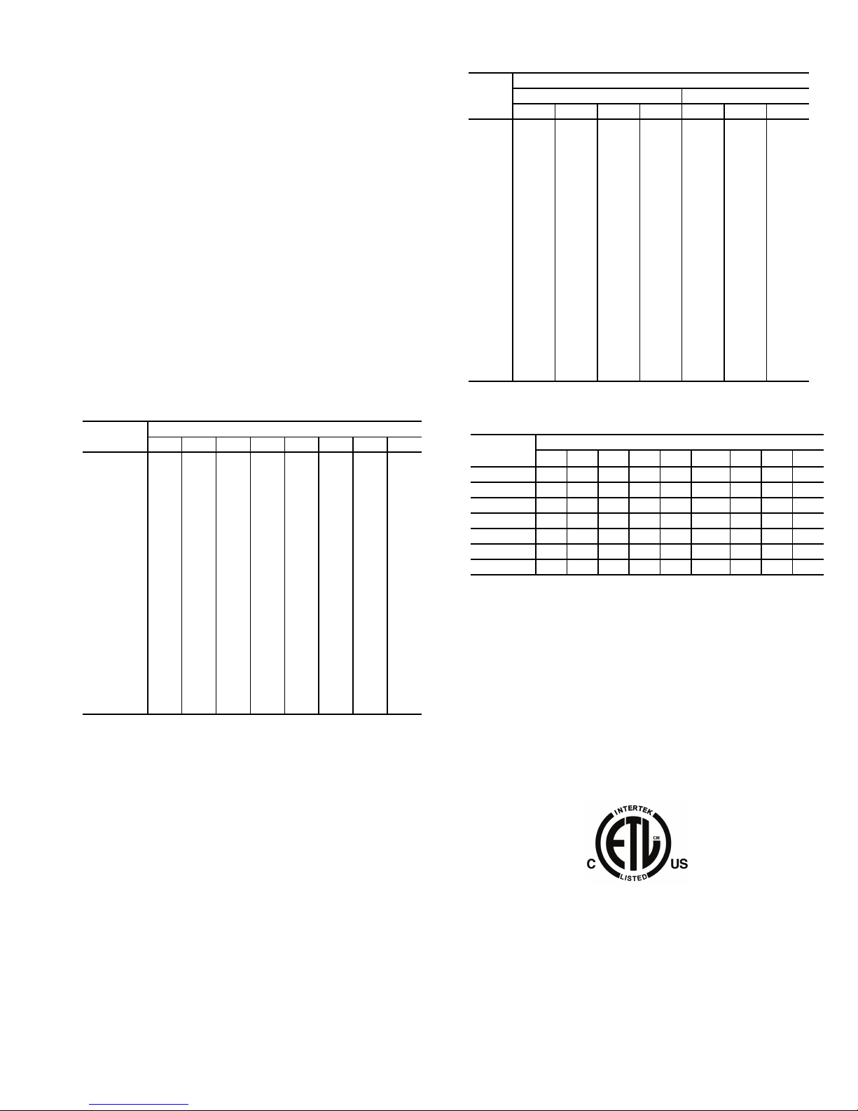
Step 7 — Make Electrical Connections — Refer to
the unit rating plate for supply voltage, motor and heater amperage, and required circuit ampacities. (See Tables 2 - 4.) The
unit wiring diagram shows all factory and field wiring. Most of
the unit motors are dual voltage that are factory wired for a
specified voltage. The motors should be checked to ensure that
they are wired for the correct voltage and rotation.
Units equipped with factory-installed motor controls and
disconnect will comply with NEC requirements for disconnect,
motor controller and motor overload protection. Separate disconnect and motor starter are not required to comply with NEC
requirements.
All field wiring should be done in accordance with all applicable local and national codes. Any factory wiring modifications without factory authorization will void all factory warranties and nullify any agency listings.
The manufacturer assumes no responsibility for any damage and/or injuries resulting from improperly installed or wired
components.
Install fan switches, thermostats and other accessories in
accordance with accessory manufacturer’s instructions and applicable wiring diagram.
Table 2 — 42BHE,BVE ELECTRIC HEATER DATA
kW
1.0 ●●——————
1.5 ●●●●————
2.0 ●●●●————
2.5 ●●●●●———
3.0 ●●●●●———
3.5 ●●●●●●——
4.0 ●●●●●●——
4.5 ●●●●●●——
5.0 ●●●●●●——
6.0 ●●●●●●●●
7.0 — ●●●●●●●
8.0 — ●●●●●●●
9.9 —— ●●●●●●
12.0 ——— ●●●●●
14.0 ———— ●●●●
15.0 ———— ●●●●
16.0 ———— ●●●●
18.0 ————— ●●●
19.9 ————— ●●●
25.0 —————— ●●
30.0 —————— ●●
35.0 ——————— ●
39.9 ——————— ●
● — Standard Offering
— — Not Offered
NOTES:
1. Stages available:
a. Single phase: 1 to 12 kW, 1 stage only
b. Three phase: 1 to 39.9 kW, 1 stage only
2. Electric Heating Capacities (Btuh) = Heater kW x 3413
3. Electric Heater Amperage for Single-phase Power = (Heater
kW x 1000)/Applied Voltage
Electric Heater Amp. for 3-phase Power = (Heater kW x 1000)/
(Applied Voltage x 1.73).
06 08 10 12 16 20 30 40
LEGEND
3 to 12 kW, 1 stage or 2 stage
4 to 39.9 kW, 1 or 2 stage
12 to 39.9 kW, 1, 2 or 3 stage
AVAILABILITY
42BHE UNIT SIZE
Table 3 — 42BHE,BVE ELECTRIC HEATER DATA
kW
115 V 208 V 240 V 277 V 208 V 240 V 480 V
1.0 8.3 4.8 4.2 3.6 2.8 2.4 1.2
1.5 12.5 7.2 6.3 5.4 4.2 3.6 1.8
2.0 16.7 9.6 8.3 7.2 5.6 4.8 2.4
2.5 20.8 12.0 10.4 9.0 6.9 6.0 3.0
3.0 25.0 14.4 12.5 10.8 8.3 7.2 3.6
3.5 29.2 16.8 14.6 12.6 9.7 8.4 4.2
4.0 33.3 19.2 16.7 14.4 11.1 9.6 4.8
4.5 37.5 21.6 18.8 16.2 12.5 10.8 5.4
5.0 — 24.0 20.8 18.1 13.9 12.0 6.0
6.0 — 28.8 25.0 21.7 16.7 14.4 7.2
7.0 — 33.7 29.2 25.3 19.4 16.8 8.4
8.0 — 38.5 33.3 28.9 22.2 19.2 9.6
9.9 — — — 35.7 27.5 23.8 11.9
12.0 — — — 43.3 33.3 28.9 14.4
14.0 — — — — 38.9 33.7 16.8
15.0 — — — — 41.6 36.1 18.0
16.0 — — — — — 38.5 19.2
18.0 ——————21.7
19.9 ——————23.9
25.0 ——————30.1
30.0 ——————36.1
35.0 ——————42.1
39.9 ——————48.0
Single-Phase Three-Phase
FULL LOAD AMPS
Table 4 — MOTOR PERFORMANCE DATA (FULL
LOAD AMPS)
VOLTAGE
V-P h-Hz
115-1-60 5.2 6.0 8.6 13.3 14.4 — — — —
208-1-60 3.0 3.6 4.8 6.6 7.4 9.4 11.0 — —
230-1-60 2.5 3.0 4.2 5.1 6.0 9.0 10.9 — —
277-1-60 2.1 2.5 3.6 5.1 5.4 8.5 8.0 — —
208-3-60 — — 2.4 3.6 3.8 6.0 6.5 8.2 14.0
230-3-60 — — 2.2 3.0 3.2 4.8 6.2 8.0 13.2
460-3-60 — — 1.1 1.5 1.9 2.8 3.1 4.0 6.6
NOTES:
1. Motor full load amps refer to National Electric Code (NEC)
amps; actual motor nameplate amps may vary.
2. NEC data extrapolated for 277 v.
3. Motors are open drip proof, ball bearing, single speed, 1750
rpm rated at continuous duty, 104 F ambient with reversible
rotation.
4. 5HP motors available only on size 40 units.
1
1
/
/
4
3
Nominal HP
1
3
/
/4111/2235
2
SERVICE SWITCHES: — The service switch is an On/Off
switch on incoming power supply to unit. Proper amperage
load must be determined before switch can be selected. The
range of the fused or non-fused service switch is 0 to 40
amps.
Amp Load =
[Motor amps + Heater amps (if required)] x 1.20.
5
Page 6
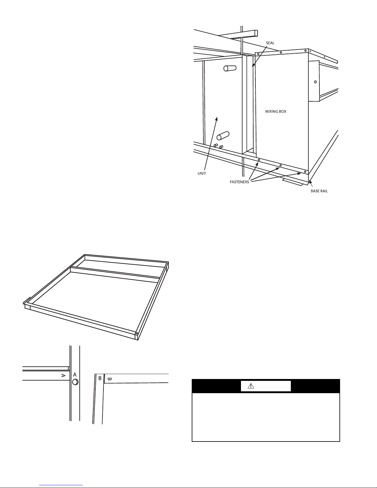
Step 8 — Make Duct Connections — Install all duct-
Fig. 5 — Assemble Base Rails
a42-4164
a42-4165
Fig. 6 — Install Mixing Box
a42-4166
work to and from unit in accordance with all applicable codes.
Duct construction must allow unit to operate within the limits of
the unit external static pressure as shown on job submittals.
Units designed to operate with ductwork may be damaged if
operated without the intended ductwork attached. Units configured to bring in outside air should have some method of low
temperature protection to prevent coil freeze-up.
Insulate all ductwork as required. Use flexible connections
to minimize duct-to-duct alignment problems and noise transmission where specified. Acoustic lining of main supply and
return duct should be considered for noise control. Noise transmission will be reduced when return grilles are located as far as
possible from the unit.
Install ductwork, accessory grilles, and plenums so that they
do not restrict access to filter.
NOTE: Prevent dirt, dust, and debris from settling in unit.
Step 9 — Install Mixing Box — Mixing boxes are
preassembled from the factory. A linkage kit consisting of
2 crankarms, 2 swivels, and either a 25 in. (unit sizes 06-16) or
a 34 in. (unit sizes 20-40) length of
field installation of the actuator.
To install the mixing box:
1. Assemble the mixing box base rails using the provided
hardware. The base rails are marked with identifying letters. See Fig. 5.
2. Place unit on the base rails. Install mixing box and attach
to base rails using the no. 8 x
tions shown in Fig. 6.
3. Seal the connection between the mixing box and the return duct flange.
NOTE: Be careful not to tape or seal the filter access
panel.
5
/16 in. rod is provided for
1
/2 in. fasteners at the loca-
Step 10 — Make Final Preparations
1. TURN POWER OFF. (Open unit electrical disconnect.)
2. Clean unit thoroughly. Remove dirt and debris from unit,
especially drain pan, drain line, motor and fan. Pour water
into drain pan to check that drain operates properly.
3. Rotate fan wheel by hand to be sure wheel is free and
does not rub housing. The 42BHE,BVE belt drives are
factory set at the speed required for the design specifications specified when ordered. These drives may be adjusted to achieve different speed by qualified personnel
during air system balancing. Refer to the Start-Up section
before energizing the unit. Check fan belt tension as described in the Service section which follows.
4. Check that a clean air filter of proper type and size is installed in unit filter rack after commissioning. See Table 1
and Clean or Replace Air Filters section. Do NOT operate unit without filter.
5. Turn on water supply. Open all valves. Check for leaks.
Recheck pitch of suspended unit.
6. Vent all air from unit coil and related piping. If air vent is
manual, release air by turning air vent screw 1
counterclockwise with screwdriver. When a steady
stream of water begins to escape, close valve. If vent is
automatic, trapped air will be released automatically. Vent
releases air slowly, usually dripping water into the drain
pan in the process.
1
/2 turns
CAUTION
The air vent provided on the unit is not intended to replace
the main system vents and may not release air trapped in
other parts of the system. Inspect the entire system for
potential air traps and vent those areas as needed. Some
systems may require repeated venting over a period of time
to properly eliminate air from the system. Failure to do so
could result in equipment damage.
6
Page 7
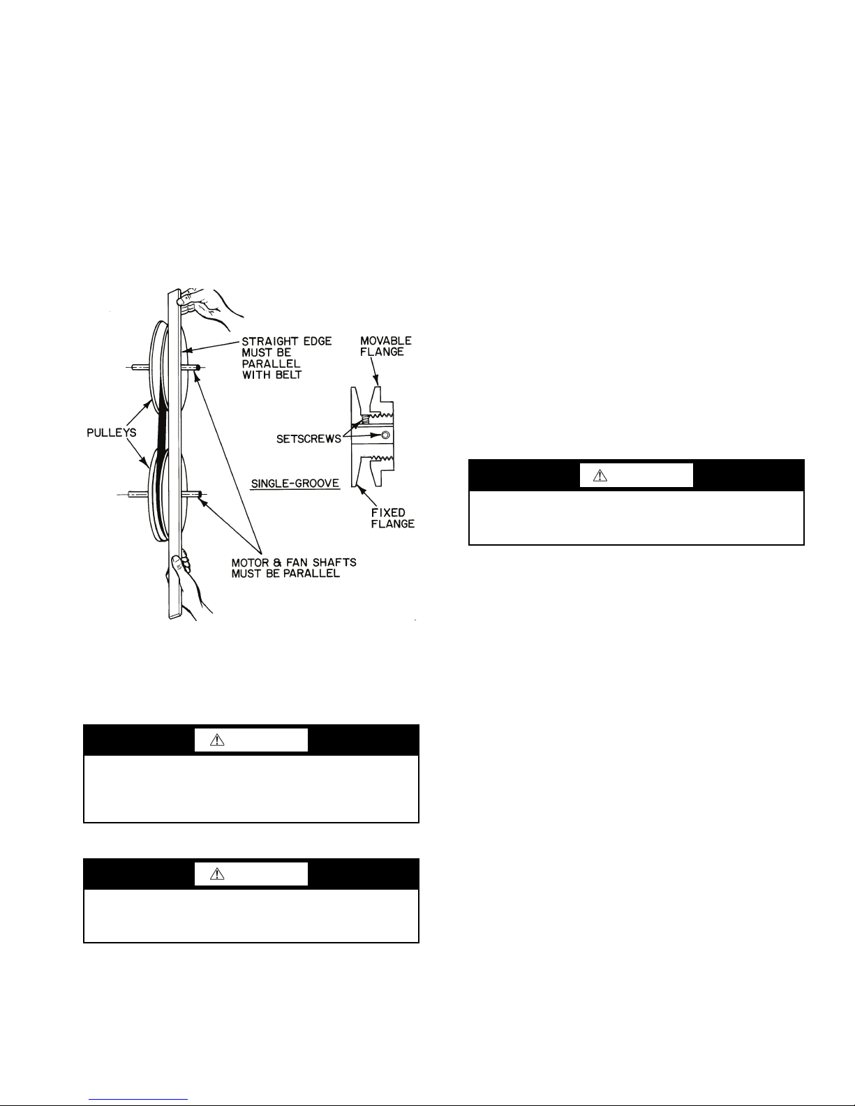
7. TURN POWER ON. (Close unit electrical disconnect.)
Fig. 7 — Fan Pulley Adjustments
a42-89tf
NOTE: Be sure power is off before making any adjustments inside unit.
8. Check fan and motor operation. Motor to fan wheel rotation must match airflow direction shown in Fig. 2 and 3.
Set unit air delivery for required blower rpm per job submittals or product data catalog. Adjust fan motor pulley
(Fig. 7) as follows:
a. Loosen setscrew on movable pulley flange.
b. Screw flange toward fixed flange to increase fan
speed and away from fixed flange to decrease speed.
c. Reset setscrew.
d. Check belt tension. The drive belt should be ten-
sioned to allow
1
/2 to 3/4-in. deflection at the mid-
point between pulleys with moderate pressure.
humid setting, condensation will form on many parts of the unit.
In order to avoid excessive condensation, water of higher
temperature should be used, approximately 65 to 70 F. Also, the
building should be as completely enclosed as possible and
outside-air supply fans and toilet and kitchen exhaust fans should
be off.
As the building temperature drops, the chilled water temperature can gradually be reduced until it reaches 50 F. At this
point, the outside-air fans can be turned on. When the chilled
water temperature is reduced to its design point, the exhaust
fans can be turned on.
Air System Balancing — All ductwork, air grilles, fil-
ters, and access doors and panels must be complete and connected to establish actual system operating conditions before
air system balancing procedures are started.
NOTE: Units are factory set for system designed operating
conditions specified at the time of order entry.
Proper belt drive alignment and tension must be maintained
when adjusting the unit fan drive speed. The drive belt tension
should not exceed
3
/16-in. deflection midway between the pulleys under 8-lb. of force. New belts tend to stretch during their
initial period of use. After 5 days of operation, check and readjust belt tension and pulley alignment if necessary. Failure to do
so may result in excessive unit noise and/or premature belt/
bearing failure.
SERVICE
Inspect the unit for loose wires, correct blower wheel operation, and loose or missing access panels or doors. Unless otherwise required for balancing and start-up procedures, units
should not be operated without proper ductwork; supply/return
air grilles, and access panels and/or doors in place.
CAUTION
Do not exceed motor nameplate FLA (full load amps).
Operator must confirm motor current draw before putting
unit into service and again after air balancing the system.
Failure to do so could result in equipment damage.
START-UP
CAUTION
Follow all safety considerations previously outlined. Failure to do so could result in personal injury or equipment
damage.
Start-up procedures vary depending upon the time of year
(summer or winter) and building characteristics (new building
or old building, occupied or unoccupied, etc.).
Start-up in the Cooling mode requires that proper care be given to avoid condensation problems. Condensation forms on surfaces that are colder than the dew point of the surrounding air. If a
unit is started and is fed low-temperature chilled water in a hot,
WARNING
Lock open and tag electrical disconnect before servicing
equipment. Failure to do so could result in personal injury
or death.
Clean Coils
1. Brush between coil fins with a stiff wire brush. Do not
bend fins. Follow up by cleaning with a vacuum cleaner.
If coil is cleaned with an air hose, take care not to drive
dirt and dust into other components.
2. Install clean air filters.
Check Drain — Check drain pan, drain line and trap at
start of each cooling season. A standard type pipe cleaner for
3
/4-in. ID pipe can ensure removal of obstructions so that condensate is carried away. Check the drain line at filter cleaning
time during the cooling season.
Fan and Motor Bearings — Fan shaft bearings are
permanently lubricated and sealed, and need no attention.
Check tag on motor for motor bearing lubrication instructions
(if any). Most motors furnished with these units are permanently lubricated.
Align Pulley — Loosen pulley setscrew(s). Align pulleys
by using a straight edge as shown in Fig. 7. Retighten setscrew(s).
Adjust Fan Belt Tension — Loosen fan motor base
mounting screws. Reposition the motor so that belt deflection
does not exceed
Retighten motor mounting screws and recheck fan belt tension.
3
/16-in. at belt midpoint under 8-lb of force.
Clean Fan Wheel — Use a stiff brush or vacuum to re-
move dirt and debris from scroll. Wipe all fan surfaces with a
damp cloth.
Clean or Replace Air Filters — At the start of each
cooling season and after each month of operation (more or less
depending on operating conditions), replace unit filter.
7
Page 8

To remove filter, slide filter out of filter rack from either side
of return-air duct collar.
THROWAWAY OR PLEATED FILTER — Replace filter
with a good quality filter of the size shown in Table 1. Do not
attempt to clean and reuse a disposable filter.
Recommended Maintenance
Quarterly
• Lubricate motor and blower bearings (if applicable)
• Check and adjust belt tension
• Change air filter
Annually — in addition to quarterly maintenance
• Inspect all wiring connections and tighten if necessary
• Check and tighten set screws on pulleys
• Clean coil and drain pan
• Clean blower wheel as needed
TROUBLESHOOTING
Excessive Condensation on Fan Coil Unit
Parts —
chilled water through a fan coil unit with its fan off. If fan cycling control is used, a water flow control valve should be installed to shut off the water when the fan stops.
The following two practices will also help avoid condensa-
tion problems:
1. Continuous fan operation with motorized chilled water
2. Continuous fan operation with thermostat control to
Excessive condensation can be caused by running
valve controlled by thermostat.
switch fan from high to low speed (instead of switching it
off).
Motor Overload — The following are causes and reme-
dies for motor trip-out on overload:
Cause: Fan delivers too much air because external stat-
ic pressure is lower than the design pressure.
Remedy: Reduce fan speed by adjusting motor pulley or
Cause: Air temperature across fan motor is too high
Remedy: Check ambient temperature on motor’s name-
changing fan shaft pulley to larger diameter.
(heating mode).
plate. Compare to actual air temperature at the
motor or at the fan discharge. If motor’s nameplate lists an ambient temperature of 104 F and
the actual air temperature is higher, either lower the air temperature or obtain a special motor
rated for high ambient temperatures.
8
Page 9

Page 10

Copyright 2011 Carrier Corporation
Manufacturer reserves the right to discontinue, or change at any time, specifications or designs without notice and without incurring obligations.
Catalog No. 04-53420006-01 Printed in U.S.A. Form 42B-3SI Pg 10 2-11 Replaces: 42B-2SI
Page 11

Start-Up Checklist
The following is a checklist to be completed before start-up:
1. General visual unit and system inspection Ye s No
2. Check that unit is level Ye s No
3. Record electrical supply voltage Ye s No
4. Check all wiring for secure connections Ye s No
5. Verify with straight edge alignment of motor and blower pulleys Ye s No
6. Tighten all set scews Ye s No
7. Confirm V-belt is properly tightened Ye s No
8. Check condensate drain connection Ye s No
9. Verify trap is deep enough Ye s No
10. Prime the trap with water Ye s No
11. Check supply and return water connections for leaks Ye s No
12. Fill systems with water by opening supply ball valve and control valve Ye s No
13. Open air vent on top of coil to vent air out of system Ye s No
14. Open return ball valve Ye s No
15. Engage power only long enough to verify proper blower rotation Ye s No
16. Check all ductwork and grilles in place Ye s No
17. Check all unit panels and filters in place Ye s No
18. Start fans, pumps, chillers, etc. Ye s No
19. Check for overload conditions of all units Ye s No
20. Check all ductwork and units for air leaks Ye s
21. Balance water systems, as required Ye s No
22. Balance air sytems, as required Ye s No
23. Record all final settings for future use Ye s No
24. Check piping and ductwork for noise or vibration Ye s No
25 Check all dampers for proper operation Ye s No
26. Verify proper cooling operation Ye s No
27. Verify proper heating operation Ye s No
28. Reinstall all covers and access panels Ye s No
29. Verify proper condensate drainage Ye s No
No
CL-1
Page 12

COMMENTS:
________________________________________________________________________________________________________
________________________________________________________________________________________________________
________________________________________________________________________________________________________
________________________________________________________________________________________________________
________________________________________________________________________________________________________
________________________________________________________________________________________________________
________________________________________________________________________________________________________
________________________________________________________________________________________________________
________________________________________________________________________________________________________
________________________________________________________________________________________________________
________________________________________________________________________________________________________
________________________________________________________________________________________________________
________________________________________________________________________________________________________
________________________________________________________________________________________________________
________________________________________________________________________________________________________
________________________________________________________________________________________________________
________________________________________________________________________________________________________
________________________________________________________________________________________________________
SIGNATURES:
Start-up
Technician _____________________________________
Date _____________________________________________
Customer
Representative __________________________________
Date _____________________________________________
CUT ALONG DOTTED LINE CUT ALONG DOTTED LINE
Copyright 2011 Carrier Corporation
Manufacturer reserves the right to discontinue, or change at any time, specifications or designs without notice and without incurring obligations.
Catalog No. 04-53420006-01 Printed in U.S.A. Form 42B-3SI Pg CL-2 2-11 Replaces: 42B-2SI
- - - - - - - - - - - - - - - - - - - - - - - - - - - - - - - - - - - - - - - - - - - - - - - - - - - - - - - - - - - - - - - - - - - - - - - - - - - - - - - - - - - - - - - - - - - - - - - - - - - - - - - - - - - - - - - - - - - - - - - - - - - - - - - - - - - - - - - - - - - - - - - - - - - - - - - - - - - - - - - - - - - - - - - - - - - - -- - - - - - - - - - - - - - - - - - - -
 Loading...