

Carrier 40UV, UH050-200, 40UH050, 40UH075, 40UH100 Installation, Start-up And Service Instructions Manual
...Page 1
40UV,UH050-200
Unit Ventilators
with Product Integrated Control (PIC)
Installation, Start-Up and Service Instructions
CONTENTS
Page
SAFETY CONSIDERATIONS ............................1
INTRODUCTION ......................................1,2
PREINSTALLATION .....................................1
Unpack and Inspect Units ..............................1
Protect Units From Damage ............................1
Prepare Jobsite for Unit Installation ....................1
Identify and Prepare Units.............................2
PHYSICAL DATA ........................................2
INSTALLATION ......................................2-24
Placing Vertical Units in Position .......................2
Placing Horizontal Units in Position ....................2
Make Piping Connections...............................8
Make Electrical Connections............................8
Actuators (Field-Supplied)..............................8
Make Duct Connections .............................. 23
Make Final Preparations .............................. 24
PRODUCT INTEGRATED CONTROL ................24-46
Physical Characteristics .............................. 24
Unit Ventilator Comfort Control Module
Installation and Field Wiring ........................ 27
Sensors .............................................. 29
Carrier Comfort Network® Interface .................. 38
Relays ................................................ 39
Actuators ............................................. 39
Direct Expansion (DX) Cooling........................ 41
DX System Design.................................... 41
Electric Heat.......................................... 42
Remote Start ......................................... 42
Fire/Smoke Status Input .............................. 42
Val ves ................................................ 43
SET-UP, CONFIGURATION, AND
OPERATION ......................................46-49
START-UP............................................. 50
SERVICE............................................50-66
Preventing Excessive Condensation on Unit.......... 50
Check Drain .......................................... 50
Fan Motor Bearings................................... 50
Fan Shaft Ball Bearing................................ 50
Clean Fan Wheel...................................... 50
Clean or Replace Air Filters........................... 50
ECM Motor Removal and Reinstallation............... 50
Blower Assembly Section Removal
and Reinstallation .................................. 52
Coil Assembly Removal and Reinstallation ........... 53
Ball Bearing Replacement ............................ 57
Blower Wheel Removal and Reinstallation ............ 62
Sleeve Bearing Replacement ......................... 63
Damper Section Removal and Reinstallation.......... 65
TESTING............................................67-71
Water Valve Tests..................................... 67
Face and Bypass Damper Tests ...................... 67
Dampers.............................................. 68
Fan Tests ............................................. 68
Filter Maintenance .................................... 68
Remote Start Input.................................... 68
Sensors .............................................. 68
Fire Shutdown Option ................................ 68
Electric Heat and Direct Expansion Cooling .......... 68
Mixed-Air Damper Sensors Final Calibration.......... 69
Testing Completion ................................... 69
Unit Diagnostics and Troubleshooting ................ 69
SAFETY CONSIDERATIONS
Installation and servicing of this unit can be hazardous due
to system pressure, electrical components and equipment
location (such as a ceiling or elevated structure). Untrained
personnel can perform the basic maintenance functions of
replacing filters. Only trained and qualified service personnel
should perform all other operations.
When installing this unit, observe precautions in the literature, tags and labels attached to the equipment, and any other
safety precautions that may apply.
• Follow all safety codes.
• Wear safety glasses and work gloves.
• Use care in handling and installing this accessory.
• Use quenching cloth for all brazing operations.
• Have fire extinguisher available for all brazing
operations.
Before performing service or maintenance operations, turn
off main power switch to the unit. Electrical shock could
cause personal injury.
INTRODUCTION
This document contains general installation instructions for
the 40UV,UH unit ventilators and information and troubleshooting of the Product Integrated Control (PIC) option.
See submittal drawings for unit configurations, dimensions,
clearances, and pipe connections. Refer to unit wiring label for
all electrical connections; follow NEC (National Electrical
Code) and local codes.
PREINSTALLATION
Unpack and Inspect Units —
from all units. Check the shipment against shipping order. If
shipment is damaged or incomplete, file claim with transportation company and advise Carrier immediately.
Remove shipping wraps
Protect Units From Damage — To maintain war-
ranty, protect units against adverse weather, theft, vandalism,
and debris on jobsite. Do not allow foreign material to fall into
drain pan. Prevent dust and debris from being deposited on
motor and fan wheels.
If the equipment is stored for any length of time before installation, it should remain in its shipping container in a clean,
dry, and climate controlled area.
Prepare Jobsite for Unit Installation — To sa ve
time and to reduce the possibility of costly errors, set up a complete sample installation in a typical room at jobsite. Check all
critical dimensions such as pipe, wire, and duct connection
requirements. Refer to job drawings and product dimension
drawings as required. Instruct all trades in their part of the
installation.
Manufacturer reserves the right to discontinue, or change at any time, specifications or designs without notice and without incurring obligations.
Book 3
Ta b 2 a
Catalog No. 534-094 Printed in U.S.A. Form 40UV,UH-6SI Pg 1 7-05 Replaces: 40UV,UH-3SI
Page 2
Identify and Prepare Units
1. Be sure power requirements match available power
source. Refer to the unit nameplate and wiring diagram.
2. Remove front (40UV) or bottom (40UH) access panels
from the unit. Retain the
5
/32-in. socket head fasteners and
panels for reinstallation later.
3. Rotate the fan shaft by hand to ensure that fans are
unrestricted and can rotate freely. Check for shipping
damage and fan obstructions.
PHYSICAL DATA
Component weight data of 40UV,UH units is provided in
Table 1 .
5. Adjust unit leveling legs so unit is level. Unit must be
level for proper operation and condensate drainage.
6. Using field-supplied fasteners, reach into unit and attach
unit to the wall using the
3
/4in. mounting holes in the
back panel.
7. Protect the unit from jobsite debris. Do not allow foreign
material to fall into drain pan. Prevent dust and debris
from being deposited on motor or fan.
Placing Horizontal Units in Position
1. Select the unit location; ensure that service clearance is
provided. Allow enough grille clearance to maintain unrestricted airflow. Make sure that ceiling is able to support
the weight of theunit. See Fig. 3-5 for nominal unit weight.
See submittal drawings and Fig. 3-5 for dimensions.
INSTALLATION
NOTE: See page 23 for additional requirements for units
ducted to multiple openings.
Units must be installed level and plumb. Failure to do so
may result in excessive vibration and/or premature failure.
2. Ensure that bottom panels have been removed from unit.
When unit is lifted, access to the
through the bottom of the unit. Hanger rods and fasteners
and other required hardware must be field supplied.
3
/4in. mounting holes is
3. Using a forklift or other mechanical lifting device, raise
Placing Vertical Units in Position
1. Select the unit location; ensure that service clearance is
provided. Allow enough grille clearance to maintain
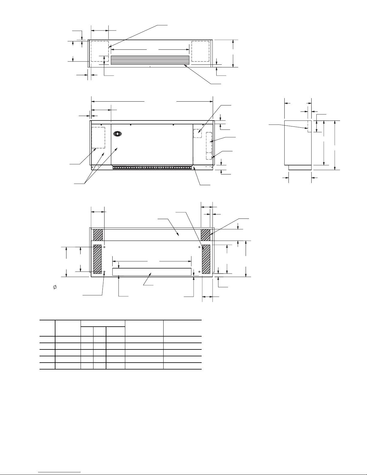
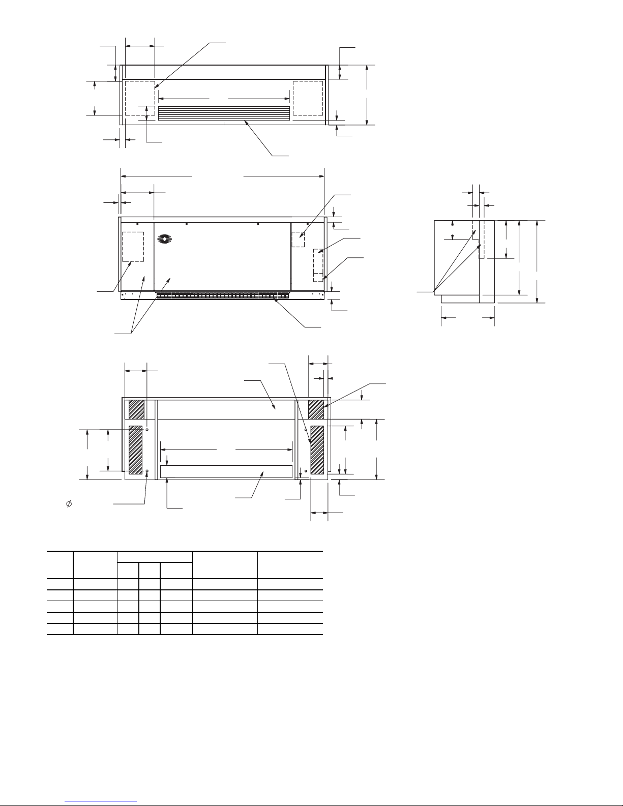
unrestricted airflow. See submittal drawings and Fig. 1
and 2 for dimensions.
2. Make sure wall behind unit is smooth and plumb; if
necessary, install furring strips on walls with irregular
surfaces or mullions. Furring strips must be positioned
behind mounting holes in unit. Fasteners, furring strips,
and other seals (if required) must be field supplied.
3. Remove all wall and floor moldings from behind the unit.
4. Move unit into position. Unit must be snug against wall
and furring strips.
the unit to the mounting position. If forklift or other
lifting device is likely to contact a painted wall surface,
protect the surface as necessary.
4. Use rods and fasteners to suspend the unit at the mounting
holes on the top of the unit. The unit must be suspended at
3
/4in. mounting holes; do not use any other locations.
the
5. If desired, install field-supplied vibration isolators. Adjust
isolators so unit is uniformly suspended and pitched.
6. To ensure proper drainage and operation, ensure unit is
level and tighten all fasteners. DO NOT mount the unit
on a slope. Pitch of horizontal suspended units can
change after coil is filled; recheck after filling coil.
7. Protect the unit from jobsite debris. Do not allow foreign
material to fall into drain pan. Prevent dust and debris
from being deposited on motor or fan.
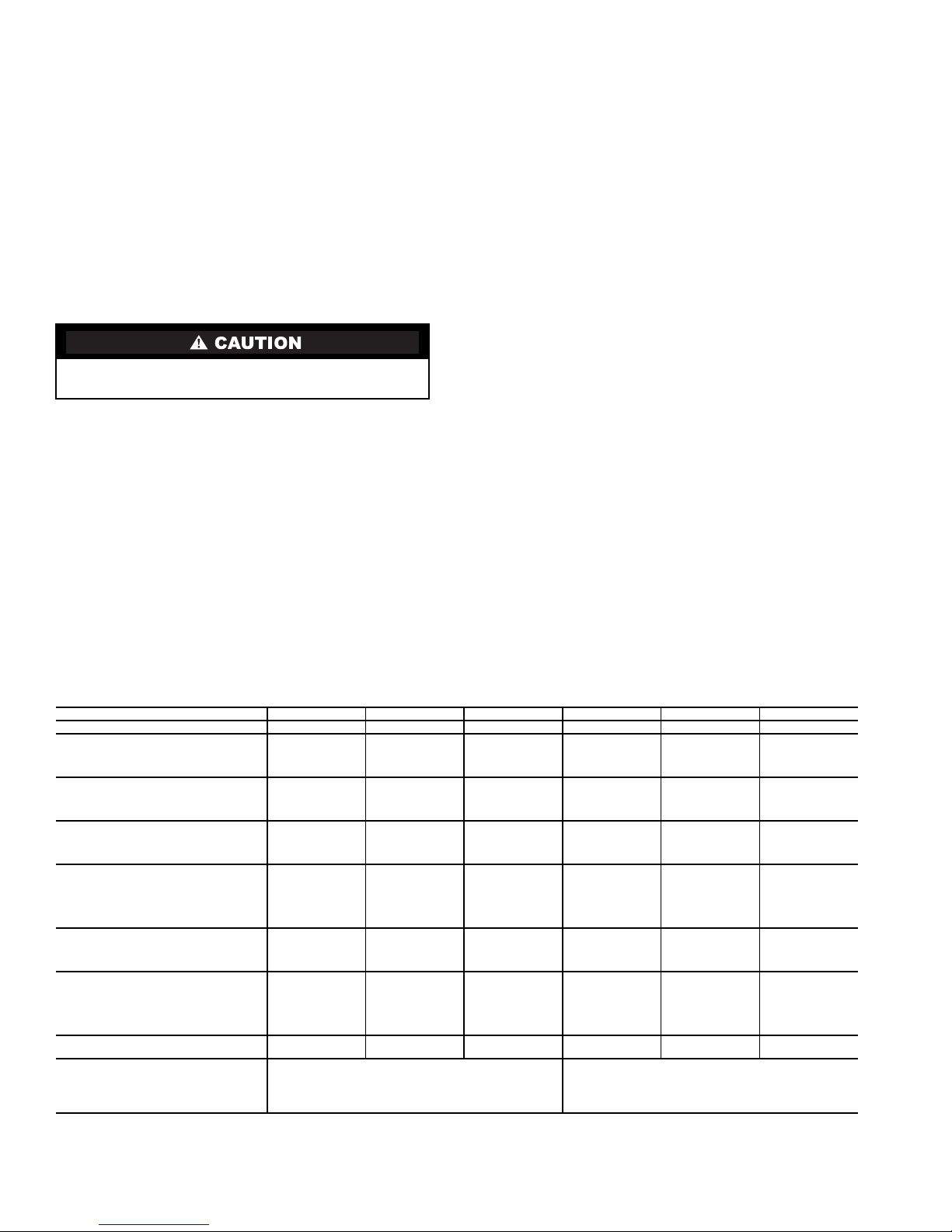
Table 1 — Physical Data
UNIT 40UV,UH 050* 075 100 125 150 200†
NOMINAL AIRFLOW (Cfm) 500 750 1000 1250 1500 2000
FANS
Quantity 123455
Diameter (in.) 8.32 8.32 8.32 8.32 8.32 9.5
Width (in.) 888886
FILTERS
Nominal Size (in.) (1 in. thick) 9
Nominal Size (in.) (2 in. thick) 9x241/
Quantity 111111
40UV SHIPPING WEIGHT**
(Approx lb)
5
/8in. Deep Unit 330 400 480 590 660 —
16
217/8in. Deep Unit 340 410 490 605 675 —
40UH SHIPPING WEIGHT**
(Approx lb)
1
30
/2in. Deep Unit — 420 500 620 690 —
36 in. Deep Unit — 500 600 740 830 —
40 in. Deep Unit — 530 640 790 880 1020
44 in. Deep Unit —————1050
40UV INSTALLED WEIGHT**
(Approx lb)
5
16
/8in. Deep Unit 315 380 460 570 640 —
7
21
/8in. Deep Unit 325 390 470 595 655 —
40UH INSTALLED WEIGHT**
(Approx lb)
1
30
/2in. Deep Unit — 405 480 600 670 —
36 in. Deep Unit — 485 580 720 810 —
40 in. Deep Unit — 515 620 770 860 1000
44 in. Deep Unit —————1030
COIL WATER WEIGHT
(Approx lb per row of coil)
COIL CONNECTIONS (in. OD) Return Supply
Water Coils with 1 to 5 Rows
Steam Coils (All Units)
DX Coils
LEGEND
DX — Direct Expansion
3
/4x241/
4
4
1.0 1.5 2.0 2.4 2.7 2.7
93/4x361/
4
9x361/
4
7
/
8
7
/
8
Suction Liquid
7
/
8
93/4x481/
4
9x481/
4
*40UV only.
†40UH 40 and 44 in. deep units only.
**Weight based on damper-controlled unit with 5-row coil and factory-installed
controls.
93/4x601/
9x601/
4
4
93/4x721/
9x721/
11/
4
4
7
/
8
8
3
/
8
93/4x721/
9x721/
4
4
2
Page 3
.78
(TYP)
10.61
(TYP)
REMOVABLE BOTTOM PANEL
(EACH END)
12.37
(TYP)
2.08
(TYP)
(UNIT SHOWN
WITH 1.00" END
CCN
CONTR
(OPTIONAL)
FRONT SERVICE
PANELS
(SEE NOTE 3)
1.00
PANELS)
OLLER
5.22
12.10 (TYP)
8.08
(TYP-SEE
NOTE 2)
W3
TOP VIEW
W1
(SEE NOTE 2)
FRONT VIEW
REMOVABLE PANEL
(
EACH END)
PIPE TUNNEL
16.63
1.70
BARSTOCK
DISCHARGE GRILLE
MOTOR
PIPING
2.00
RECESSED RETURN
AIR/KICK PANEL
7.04 (TYP)
1.54 (TYP)
7.00 (TYP)
TUNNEL
ELECTRICAL
BOX
NON-FUSED
DISCONNECT
SWITCH
2.95
PIPING ACCESS
OPENING
(EACH END)
16.63
2.40
13.90
7.02
27.30
30.00
RIGHT SIDE VIEW
(MOUNTING
HOLES-TYP4 PLACES)
UNIT
40UV
18.25
(TYP)
.75
AIRFLOW
(cfm)
15.00
(TYP)
4.50
DIMENSIONS (in.) APPROXIMATE
W1 W2 W3
WEIGHT (lb)
W2
REAR VIEW
SHIPPING
OUTSIDE AIR
OPENING
.90
APPROXIMATE
INSTALLED
WEIGHT (lb)
050 500 50 24 16.60 330 315
075 750 62 36 31.67 400 380
100 1000 74 48 46.74 480 460
125 1250 86 60 61.81 590 570
150 1500 98 72 78.47 660 640
Fig. 1 — 40UV Dimensions — 165/8-in. Deep Units
(Standard)
17.50
6.75 (TYP)
(TYP)
22.00
(TYP)
2.00
(TYP)
LEGEND
CCN — Carrier Comfort Network®
NOTES:
1. All dimensions are in inches.
2. Dimension does not include end panels.
3. Three front panels provided for service access.
4. Motor and electrical power input box on right side of
unit. Box includes fan speed switch, On/Off switch and
non-fused disconnect switch.
5. Connection hand is determined by facing discharge of
unit.
3
Page 4
5.98
(TYP)
10.61
(TYP)
REMOVABLE BOTTOM PANEL
(EACH END)
5.20
12.37
(TYP)
2.08
(TYP)
(UNIT SHOWN
WITH 1.00" END
CCN
CONTROLLER
(OPTIONAL)
1.00
PANELS)
FRONT SERVICE
PANELS
(SEE NOTE 3)
5.22
12.00 (TYP)
8.08
(TYP-SEE
NOTE 2)
W3
TOP VIEW
W1
(SEE NOTE 2)
FRONT VIEW
REMOVABLE PANEL
(EACH END)
PIPE TUNNEL
STOCK
BAR
DISCHARGE GRILLE
MOTO R
2.00
3.00
RECESSED RETURN
AIR/KICK PANEL
7.04 (TYP)
1.54 (TYP)
7.00 (TYP)
21.88
1.70
ELECTRICAL
BOX
NON-FUSED
DISCONNECT
SWITCH
PIPING ACCESS
OPENING
(EACH END)
PIPING
TUNNEL
2.40
1.74
7.02
13.75
27.30
30.00
19.37
END VIEW
(MOUNTING
HOLES-TYP4 PLACES)
UNIT
40UV
15.00
18.25
(TYP)
.75
AIRFLOW
(cfm)
(TYP)
4.50
DIMENSIONS (in.) APPROXIMATE
W1 W2 W3
W2
OUTSIDE AIR
OPENING
REAR VIEW
SHIPPING
WEIGHT (lb)
0.90
APPROXIMATE
INSTALLED
WEIGHT (lb)
050 500 50 24 16.60 340 325
075 750 62 36 31.67 410 390
100 1000 74 48 46.74 490 470
125 1250 86 60 61.81 605 595
150 1500 98 72 78.47 675 655
Fig. 2 — 40UV Dimensions — 217/8-in. Deep Units
(With Piping Chase)
17.50
(TYP)
6.75 (TYP)
22.00
(TYP)
2.00
(TYP)
LEGEND
CCN — Carrier Comfort Network®
NOTES:
1. All dimensions are in inches.
2. Dimension does not include end panels.
3. Three front panels provided for service access.
4. Motor and electrical power input box on right side
of unit. Box includes fan speed switch, On/Off
switch and non-fused disconnect switch.
5. Connection hand is determined by facing discharge of unit.
4
Page 5
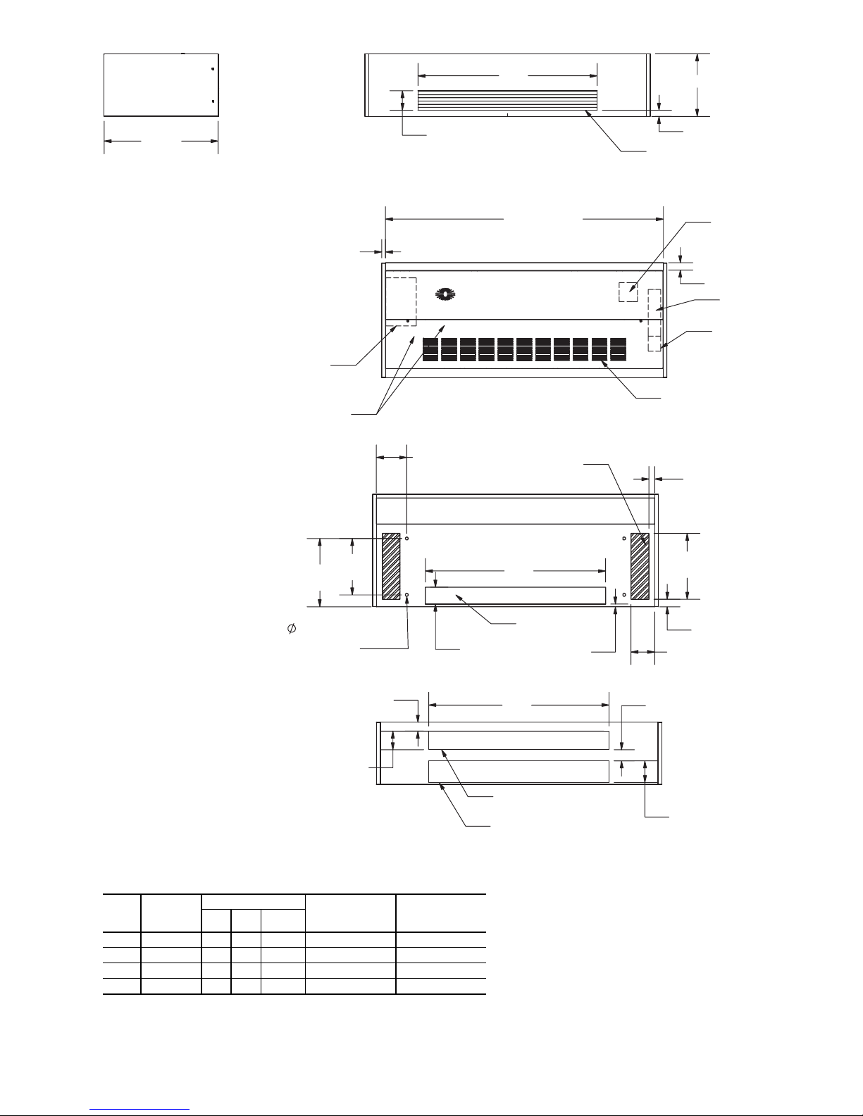
W3
16.63
30.50
LEFT SIDE VIEW
(UNIT SHOWN
WITH 1.00" END
CCN
CONTROLLER
(OPTIONAL)
BOTTOM SERVICE
PANELS
(SEE NOTE 3)
1.00
PANELS)
5.22
8.08
(TYP-SEE
NOTE 2)
FRONT VIEW
W1
(SEE NOTE 2)
BOTTOM VIEW
REMOVABLE PANEL
(EACH END)
1.70
BARSTOCK
DISCHARGE GRILLE
(OPTIONAL)
MOTOR
2.00
ELECTRICAL
BOX
NON-FUSED
DISCONNECT
SWITCH
RETURN AIR
LOUVER
(OPTIONAL)
ED PANEL
1.54
(TYP)
15.00
18.25
(TYP)
(TYP)
.75
(MOUNTING
HOLES-TYP4 PLACES)
2.27
5.00
LEGEND
CCN — Carrier Comfort Network®
UNIT
AIRFLOW
40UH
075 750 62 36 31.67 420 405
100 1000 74 48 46.74 500 480
125 1250 86 60 61.81 620 600
150 1500 98 72 78.47 690 670
(cfm)
DIMENSIONS (in.) APPROXIMATE
W1 W2 W3
SHIPPING
WEIGHT (lb)
APPROXIMATE
INSTALLED
WEIGHT (lb)
W2
OUTSIDE AIR
OPENING
4.50
1.00
TOP VIEW
W2
REAR OUTSIDE
AIR OPENING (OPTIONAL)
REAR RETURN
AIR OPENING (OPTIONAL)
REAR VIEW
NOTES:
1. All dimensions are in inches.
2. Dimension does not include end panels.
3. Two bottom panels provided for service access.
4. Motor and electrical power input box on right side of
unit. Box includes fan speed switch, On/Off switch and
non-fused disconnect switch.
5. Connection hand is determined by facing discharge of
unit.
17.50
(TYP)
2.50
(TYP)
6.75 (TYP)
3.00
5.75
Fig. 3 — 40UH Dimensions — 301/2-in. Deep Units
5
Page 6
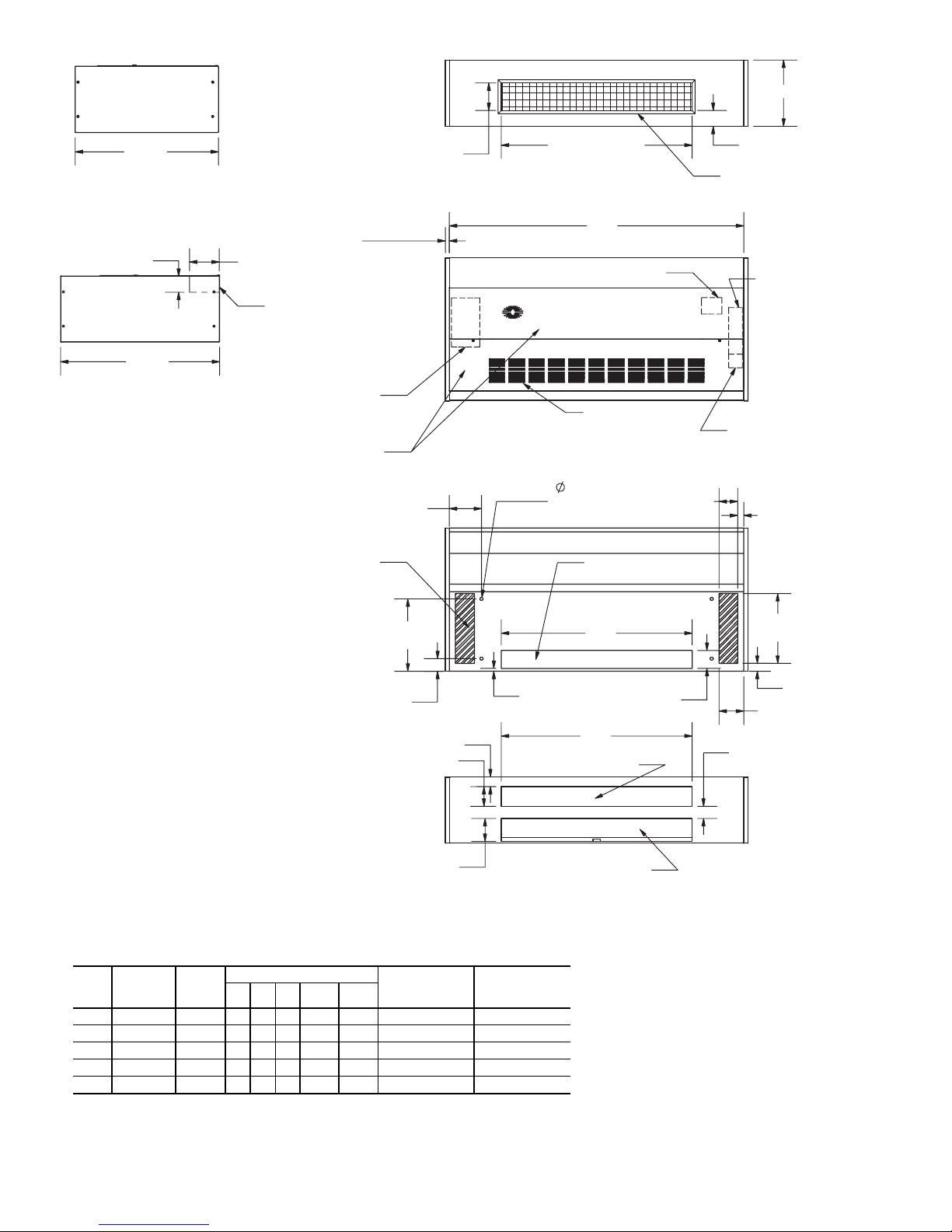
16.63
36.00
LEFT SIDE VIEW
(SIZES 075 TO 150)
4.00
40.00
LEFT SIDE VIEW
(SIZE 200)
(UNIT SHOWN
7.50
WITH 1.00"
END PANELS)
PIPE
TUNNEL
CCN
CONTROLLER
(OPTIONAL)
BOTTOM SERVICE
PANELS
(SEE NOTE 3)
REMOVABLE PANEL
(EACH EN
D)
1.00
(OPENING)
8.00
(TYP-SEE
NOTE 2)
W5
W3 (OPENING)
FRONT VIEW
W1
(SEE NOTE 2)
MOTOR
RETURN AIR
LOUVERED PANEL
(OPTIONAL)
BOTTOM VIEW
.75
(MOUNTING HOLESTYP-4 PLACES)
TOP OUTSIDE AIR
OPENING (OPTIONAL)
4.00
(TO OPENING)
DOUBLE DEFLECTION
DISCHARGE GRILLE
(OPTIONAL)
ELECTRICAL
BOX
NON-FUSED
DISCONNECT
SWITCH
4.75
(TYP)
1.00 (TYP)
W4
(TYP)
3.67
(TYP)
2.27
5.00
5.75
LEGEND
CCN — Carrier Comfort Network®
UNIT
40UH
AIRFLOW
(cfm)
DEPTH
(in.)
DIMENSIONS (in.) APPROXIMATE
W1 W2 W3 W4 W5
SHIPPING
WEIGHT (lb)
APPROXIMATE
INSTALLED
WEIGHT (lb)
075 750 36 62 36 36 18.67 7.00 500 485
100 1000 36 74 48 48 18.67 7.00 600 580
125 1250 36 86 60 60 18.67 7.00 740 720
150 1500 36 98 72 72 18.67 7.00 830 810
200 2000 40 98 72 72 26.92 10.00 1020 1000
W2
1.25
REAR OUTSIDE AIR
OPENING (OPTIONAL)
REAR RETURN AIR
OPENING (OPTIONAL)
TOP VIEW
W2
REAR VIEW
NOTES:
1. All dimensions are in inches.
2. Dimension does not include end panels.
3. Two bottom panels provided for service
access.
4. Motor and electrical power input box on
right side of unit. Box includes fan speed
switch, On/Off switch and non-fused disconnect switch.
5. Connection hand is determined by facing
discharge of unit.
4.50
17.50
(TYP)
2.50
(TYP)
6.75 (TYP)
3.00
Fig. 4 — 40UH Dimensions — Front Discharge Units
6
Page 7
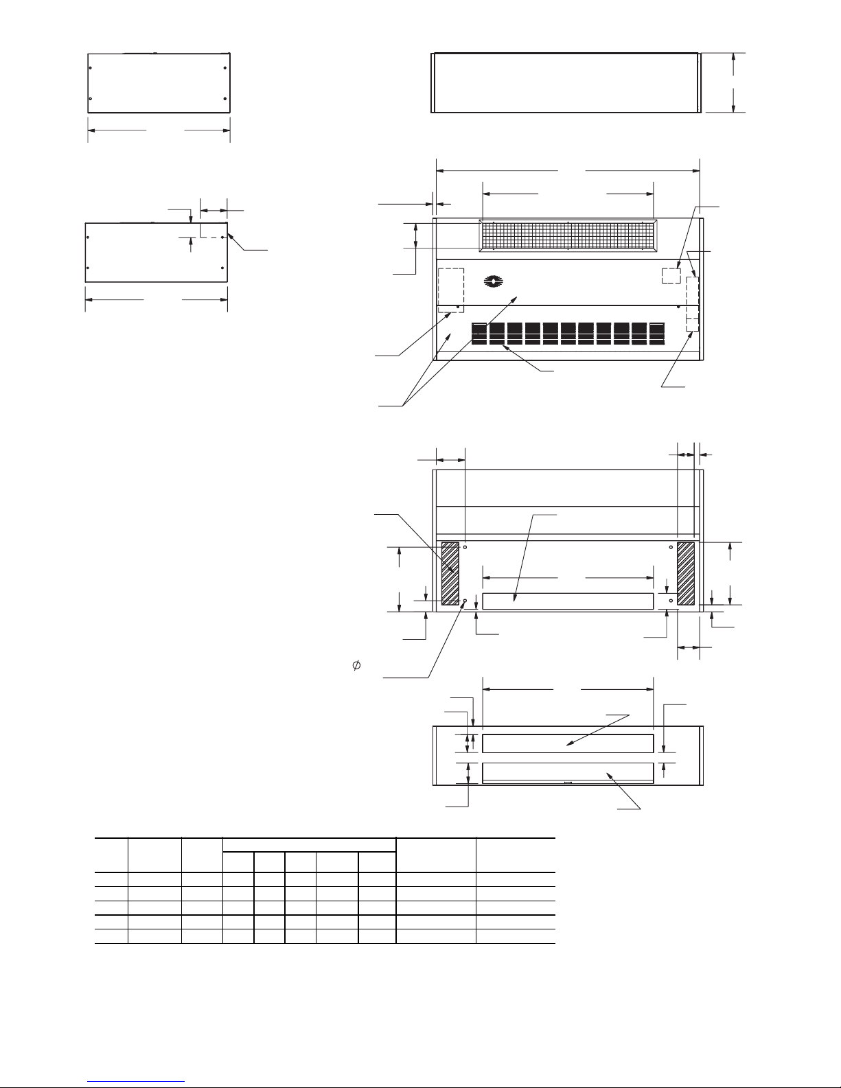
16.63
40.00
LEFT SIDE VIEW
(SIZES 075 TO 150)
4.00
44.00
LEFT SIDE VIEW
(SIZE 200)
7.50
(UNIT SHOWN
END PANELS)
PIPE
TUNNEL
CCN
CONTROLLER
(OPTIONAL)
BOTTOM SERVICE
PANELS
(SEE NOTE 3)
REMOVABLE PANEL
(EACH EN
1.00
WITH 1.00"
W5 (OPENING)
(TYP-SEE
NOTE 2)
D)
8.00
FRONT VIEW
W1
(SEE NOTE 2)
W3
(OPENING)
RETURN AIR
LOUVERED PANEL
(OPTIONAL)
BOTTOM VIEW
TOP OUTSIDE AIR
OPENING (OPTIONAL)
4.75
(TYP)
MOTOR
ELECTRICAL
BOX
NON-FUSED
SCONNECT
DI
SWITCH
1.00 (TYP)
W4
(TYP)
3.67
(TYP)
(MOUNTING HOLES-
TYP-4 PLACES)
LEGEND
.75
2.27
5.00
5.75
CCN — Carrier Comfort Network®
UNIT
AIRFLOW
40UH
(cfm)
075 750 40 62 36 36 18.67 7.00 530 515
100 1000 40 74 48 48 18.67 7.00 640 620
125 1250 40 86 60 60 18.67 7.00 790 770
150 1500 40 98 72 72 18.67 7.00 880 860
200 2000 44 98 72 72 26.92 10.00 1050 1030
DEPTH
(in.)
DIMENSIONS (in.) APPROXIMATE
W1 W2 W3 W4 W5
SHIPPING
WEIGHT (lb)
APPROXIMATE
W2
1.25
TOP VIEW
W2
REAR OUTSIDE AIR
OPENING (OPTIONAL)
REAR RETURN AIR
OPENING (OPTIONAL)
REAR VIEW
NOTES:
INSTALLED
WEIGHT (lb)
17.50
(TYP)
2.50
4.50
3.00
1. All dimensions are in inches.
2. Dimension does not include end panels.
3. Two bottom panels provided for service
access.
4. Motor and electrical power input box on
right side of unit. Box includes fan
speed switch, On/Off switch and nonfused disconnect switch.
5. Connection hand is determined by facing discharge of unit.
(TYP)
6.75 (TYP)
Fig. 5 — 40UH Dimensions — Down Discharge Plenum
7
Page 8
Make Piping Connections — Access to piping is
available through the access panels at the front, top, or end of
the vertical unit (horizontal access from bottom or side). Route
piping through the pipe tunnel or the unit’s back panel or floor
panel. Metal blank-off panels must be trimmed to complete
piping installation. All piping connections must be performed
by qualified personnel in accordance with local and national
codes.
DRAIN CONNECTIONS — Condensate drain connections
are located on each end of the drain pan near the bottom of the
unit. Condensate drain line must be
galvanized pipe, PVC or similar plastic pipe. Install drain line
in accordance with all applicable codes. Insulate the drain
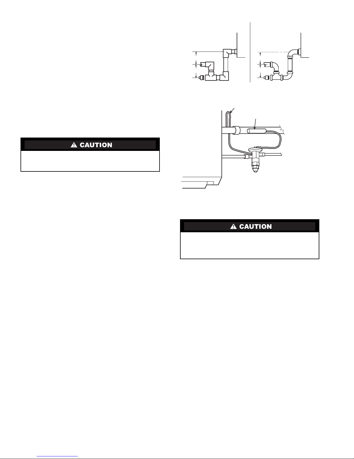
line to prevent sweating. See Fig. 6 for typical drain trap
construction.
Units with cooling coils require traps to prevent air from
entering the condensate fitting and preventing proper drainage.
Drain must flow downhill from the unit a minimum of
per ft. Drain must be free and clear at all times.
3
/4in. copper tubing,
1
/8in.
3/4"
PVC OR COPPER
3" MIN
2" MIN
3" MIN
2" MIN
3/4"
GALVANIZED PIPE
Fig. 6 — Typical Condensate Drain Trap
Construction
EQUALIZER
SENSING BULB (CLAMPED TO
SUCTION LINE AND INSULATED)
SUCTION LINE
Insulate drain lines to prevent condensate. Care must be
taken to avoid interference with control panel on left side
drain.
WATER SUPPLY/RETURN CONNECTIONS — Install piping in accordance with all applicable codes. All piping must be
supported separately from coils.
Water supply must be connected so that entering water is on
leaving-air side of coil. See the connection labels on the unit to
locate the inlet. Coils must be adequately vented to prevent air
binding. Be sure valves are in proper operating position and are
easily accessible for adjustment.
If coil and valve package connections will be made with a
solder joint, care should be taken to ensure that components in
the valve package are not subjected to high temperatures which
may damage seals or other materials. Many 2-position electric
control valves are provided with a manual operating lever. This
lever should be in the OPEN position during all soldering
operations.
If coil connection is made with a union, the coil side of the
union must be prevented from turning (it must be backed up)
during tightening. Do not overtighten! Overtightening will dis-
tort (egg shape) the union seal surface and destroy the union.
NOTE: A freezestat is factory-installed when a hot water/steam
coil is installed.
STEAM CONNECTIONS — On units with steam heating
coils, the maximum steam pressure applied to the unit should
never exceed 10 psig (operating pressure 6 psig).
DIRECT EXPANSION REFRIGERANT PIPING — Use the
condensing unit manufacturer’s recommended line sizes and
requirements. Perform leak test using nitrogen. Evacuate and
charge per recommended heating, ventilation, and air conditioning (HVAC) procedures and all applicable codes. Insulate
suction line after leak test up to the coil section end plate for
correct operation and to eliminate sweating. Use refrigerantgrade copper lines only. The unit is NOT to be applied as a
heat pump.
See Fig. 7 for refrigerant piping connections with recommended locations for the thermostatic expansion valve (TXV)
and sensing bulb.
HYDRONIC COIL PIPING — When all joints are complete,
perform hydrostatic test for leaks. Vent all coils at this time.
Check interior unit piping for signs of leakage from shipping
damage or mishandling. If leaks are found, notify a Carrier
representative before initiating any repairs. Release trapped air
from system (refer to Make Final Preparations section).
LIQUID LINE
NOTE: Follow TXV manufacturer’s instructions.
Fig. 7 — Typical TXV (Thermostatic Expansion
Valve) Installation
All water coils must be protected from freezing after initial
filling with water. Even if system is drained, unit coils may
still have enough remaining water to cause damage when
exposed to temperatures below freezing.
Following the hydrostatic test, insulate all piping up to the
coil section end plate to prevent sweating.
To ensure compliance with building codes, restore the structure’s original fire resistance rating by sealing all holes with
material carrying the same fire rating as the structure.
Make Electrical Connections — Refer to unit serial
plate for required supply voltage, fan and heater amperage, and
required circuit ampacities. Refer to unit wiring diagram for
unit and field wiring. See Tables 2-4 for electrical data.
All input power wiring connections are accessed through
the electrical panel on front right-hand side of the unit. Use the
openings that are for the piping connections. See the dimensional drawings Fig. 1-5 for electrical box connections.
The fan motor should never be controlled by any wiring or
device other than the factory-supplied switch or thermostat/
switch combination unless prior factory authorization is obtained. Fan motor may be temporarily wired for use during
construction only with prior factory approval and only in strict
accordance with the instructions issued at that time.
All electrical connections should be made by qualified personnel and be in accordance with governing codes and ordinances. Any modification of unit wiring without factory authorization
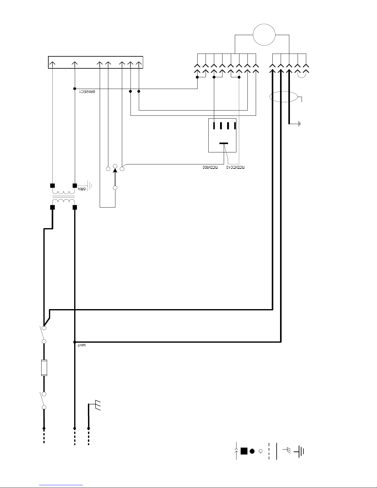
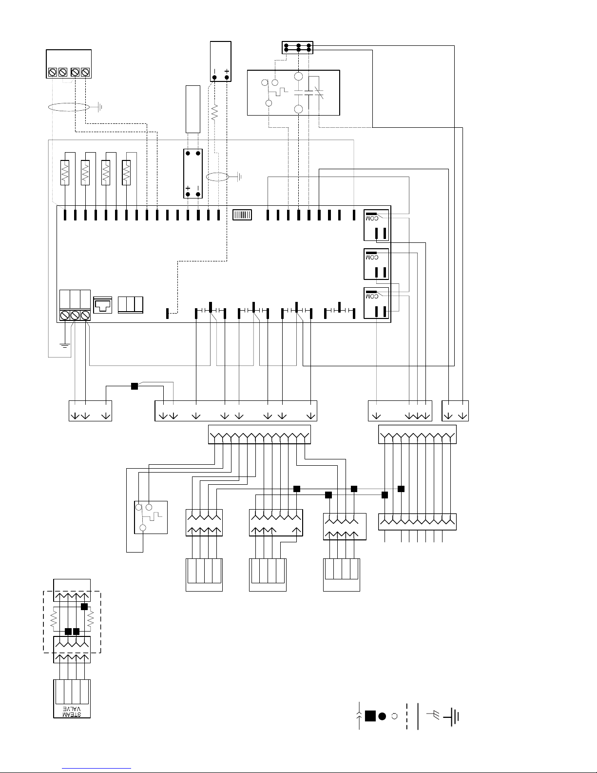
will invalidate all factory warranties and nullify any agency listings. See Fig. 8A and 8B for typical wiring connections for basic
unit with CCN (Carrier Comfort Network®) controls.
Actuators (Field-Supplied) — Field-supplied actuators
must be mounted on
1
/2in. diameter damper shafts.
8
Page 9
Table 2 — Electric Heater Data for Units with PSC Motor
UNIT HP
NOMINAL
V/Ph/Hz
NUMBER
OF
ELEMENTS
3 17.2 90 21.5 25 3.2
208/1/60
4 22.2 97 27.8 30 4.2
5 27.3 104 34.1 35 5.3
6 32.3 110 40.4 45 6.3
3 19.5 97 24.4 25 4.2
240/1/60
4 25.3 106 31.7 35 5.6
5 31.2 115 39.0 40 7.0
6 37.0 124 46.3 50 8.4
3 16.8 97 21.0 25 4.2
4 21.8 106 27.3 30 5.6
5 26.9 115 33.6 35 7.0
6 31.9 124 39.9 40 8.4
3 10.8 90 13.5 15 3.2
4 15.8 97 19.8 20 4.2
5 19.5 104 24.4 25 5.3
40UV050
(at 500 Cfm)
277/1/60
1
/
5
208/3/60
6 19.5 110 24.4 25 6.3
3 12.1 97 15.1 20 4.2
240/3/60
4 17.9 106 22.4 25 5.6
5 22.2 115 27.8 30 7.0
6 22.2 124 27.8 30 8.4
3 6.0 97 7.5 15 4.2
460/3/60
4 8.9 106 11.1 15 5.6
5 11.0 115 13.8 15 7.0
6 11.0 124 13.8 15 8.4
LEGEND NOTES:
DX — Direct Expansion
FLA — Full Load Amps
LAT — Leaving-Air Temperature at 70 F Entering-Air
Temperature
MCA — Unit Minimum Circuit Ampacity
MOCP — Maximum Overcurrent Protection (Maximum Fuse Size
or Circuit Breaker Amps)
PSC — Permanent Split Capacitor
FLA
LAT
(F)
MCA MOCP
TOTAL
CAPACITY
(kW)
1. LAT (Leaving Air Temperature)(F) is measured at nominal cfm.
2. Water and DX coil used on electric heat units have left-hand
coil connections.
3. Electric heat is available in the reheat position only and connections are on the right side.
4. Face and bypass units are available with 3 heating elements
only.
9
Page 10
Table 2 — Electric Heater Data for Units with PSC Motor (cont)
UNIT HP
NOMINAL
V/Ph/Hz
NUMBER
OF
ELEMENTS
3 23.7 89 29.6 30 4.5
208/1/60
4 30.9 96 38.6 40 6.0
5 38.1 102 47.6 50 7.5
6 45.3 108 56.7 60 9.0
3 27.0 96 33.8 35 6.0
240/1/60
4 35.3 104 44.2 45 8.0
5 43.7 113 54.6 60 10.0
6 52.0 121 65.0 70 12.0
3 23.3 96 29.1 30 6.0
4 30.5 104 38.1 40 8.0
5 37.7 113 47.1 50 10.0
6 44.9 121 56.2 60 12.0
3 14.5 89 18.2 20 4.5
4 21.7 96 27.2 30 6.0
5 27.0 102 33.8 35 7.5
40UV,UH075
(at 750 Cfm)
277/1/60
1
/
5
208/3/60
6 27.0 108 33.8 35 9.0
3 16.5 96 20.6 25 6.0
240/3/60
4 24.8 104 31.0 35 8.0
5 30.9 113 38.6 40 10.0
6 30.9 121 38.6 40 12.0
3 8.2 96 10.2 15 6.0
460/3/60
4 12.3 104 15.4 20 8.0
5 15.4 113 19.2 20 10.0
6 15.4 121 19.2 20 12.0
LEGEND NOTES:
DX — Direct Expansion
FLA — Full Load Amps
LAT — Leaving-Air Temperature at 70 F Entering-Air
Temperature
MCA — Unit Minimum Circuit Ampacity
MOCP — Maximum Overcurrent Protection (Maximum Fuse Size
or Circuit Breaker Amps)
PSC — Permanent Split Capacitor
FLA
LAT
(F)
MCA MOCP
TOTAL
CAPACITY
(kW)
1. LAT (Leaving Air Temperature)(F) is measured at nominal cfm.
2. Water and DX coil used on electric heat units have left-hand
coil connections.
3. Electric heat is available in the reheat position only and connections are on the right side.
4. Face and bypass units are available with 3 heating elements
only.
10
Page 11
Table 2 — Electric Heater Data for Units with PSC Motor (cont)
UNIT HP
NOMINAL
V/Ph/Hz
NUMBER
OF
ELEMENTS
3 30.9 89 38.6 40 6.0
208/1/60
4 40.5 95 50.7 60 8.0
5 50.2 102 62.7 70 10.0
6 59.8 108 74.7 80 11.9
3 35.3 96 44.2 45 8.0
240/1/60
4 46.5 104 58.1 60 10.7
5 57.6 112 72.0 80 13.3
6 68.7 121 85.8 90 16.0
3 30.5 96 38.1 40 8.0
4 40.1 104 50.1 60 10.7
5 49.7 112 62.2 70 13.3
6 59.4 121 74.2 80 16.0
3 18.7 89 23.4 25 6.0
4 28.3 95 35.4 40 8.0
5 35.4 102 44.3 45 10.0
40UV,UH100
(at 1000 Cfm)
277/1/60
1
/
5
208/3/60
6 35.4 108 44.3 45 11.9
3 21.3 96 26.6 30 8.0
240/3/60
4 32.4 104 40.5 45 10.7
5 40.5 112 50.7 60 13.3
6 40.5 121 50.7 60 16.0
3 10.6 96 13.2 15 8.0
460/3/60
4 16.1 104 20.1 25 10.7
5 20.2 112 25.2 30 13.3
6 20.2 121 25.2 30 16.0
LEGEND NOTES:
DX — Direct Expansion
FLA — Full Load Amps
LAT — Leaving-Air Temperature at 70 F Entering-Air
Temperature
MCA — Unit Minimum Circuit Ampacity
MOCP — Maximum Overcurrent Protection (Maximum Fuse Size
or Circuit Breaker Amps)
PSC — Permanent Split Capacitor
FLA
LAT
(F)
MCA MOCP
TOTAL
CAPACITY
(kW)
1. LAT (Leaving Air Temperature)(F) is measured at nominal cfm.
2. Water and DX coil used on electric heat units have left-hand
coil connections.
3. Electric heat is available in the reheat position only and connections are on the right side.
4. Face and bypass units are available with 3 heating elements
only.
11
Page 12
Table 2 — Electric Heater Data for Units with PSC Motor (cont)
UNIT HP
NOMINAL
V/Ph/Hz
NUMBER
OF
ELEMENTS
3 38.1 89 47.6 50 7.5
208/1/60
4 50.1 96 62.7 70 10.0
5 62.2 102 77.7 80 12.5
6 74.2 108 92.8 100 15.0
3 43.7 96 54.6 60 10.0
240/1/60
4 57.6 104 71.9 80 13.3
5 71.4 113 89.3 90 16.7
6* 85.3 121 106.7 110 20.0
3 37.7 96 47.1 50 10.0
4 49.7 104 62.2 70 13.3
5 61.8 113 77.2 80 16.7
6 73.8 121 92.2 100 20.0
3 22.9 89 28.6 30 7.5
4 34.9 96 43.6 45 10.0
5 43.7 102 54.7 60 12.5
40UV,UH125
(at 1250 Cfm)
277/1/60
1
/
5
208/3/60
6 43.7 108 54.7 60 15.0
3 26.1 96 32.6 35 10.0
240/3/60
4 40.0 104 50.0 50 13.3
5 50.2 113 62.7 70 16.7
6 50.2 121 62.7 70 20.0
3 13.0 96 16.2 20 10.0
460/3/60
4 19.9 104 24.9 25 13.3
5 25.0 113 31.3 35 16.7
6 25.0 121 31.3 35 20.0
LEGEND
DX — Direct Expansion
FLA — Full Load Amps
LAT — Leaving-Air Temperature at 70 F Entering-Air
Temperature
MCA — Unit Minimum Circuit Ampacity
MOCP — Maximum Overcurrent Protection (Maximum Fuse Size
or Circuit Breaker Amps)
PSC — Permanent Split Capacitor
*Left hand coil connections only.
FLA
LAT
(F)
NOTES:
1. LAT (Leaving Air Temperature)(F) is measured at nominal cfm.
MCA MOCP
TOTAL
CAPACITY
(kW)
2. Water and DX coil used on electric heat units have left-hand
coil connections.
3. Electric heat is available in the reheat position only and connections are on the right side.
4. Face and bypass units are available with 3 heating elements
only.
12
Page 13
Table 2 — Electric Heater Data for Units with PSC Motor (cont)
UNIT HP
NOMINAL
V/Ph/Hz
NUMBER
OF
ELEMENTS
3 45.3 89 56.7 60 9.0
208/1/60
4 59.8 96 74.7 80 12.0
5 74.2 102 92.8 100 15.0
6* 88.7 108 110.8 125 18.0
3 52.0 96 65.0 70 12.0
240/1/60
4 68.7 104 85.8 90 16.0
5* 85.3 113 106.7 110 20.0
6 —————
3 44.9 96 56.2 60 12.0
4 59.4 104 74.2 80 16.0
5 73.8 113 92.3 100 20.0
6 —————
3 27.0 89 33.8 35 9.0
4 41.5 96 51.9 60 12.0
5 52.1 102 65.1 70 15.0
40UV,UH150
(at 1500 Cfm)
277/1/60
1
/
5
208/3/60
6 52.1 108 65.1 70 18.0
3 30.9 96 38.6 40 12.0
240/3/60
4 47.6 104 59.5 60 16.0
5 59.8 113 74.8 80 20.0
6 59.8 121 74.8 80 24.0
3 15.4 96 19.2 20 12.0
460/3/60
4 23.7 104 29.6 30 16.0
5 29.8 113 37.3 40 20.0
6 29.8 121 37.3 40 24.0
LEGEND
DX — Direct Expansion
FLA — Full Load Amps
LAT — Leaving-Air Temperature at 70 F Entering-Air
Temperature
MCA — Unit Minimum Circuit Ampacity
MOCP — Maximum Overcurrent Protection (Maximum Fuse Size
or Circuit Breaker Amps)
PSC — Permanent Split Capacitor
*Left hand coil connections only.
FLA
LAT
(F)
NOTES:
1. LAT (Leaving Air Temperature)(F) is measured at nominal cfm.
MCA MOCP
TOTAL
CAPACITY
(kW)
2. Water and DX coil used on electric heat units have left-hand
coil connections.
3. Electric heat is available in the reheat position only and connections are on the right side.
4. Face and bypass units are available with 3 heating elements
only.
13
Page 14
Table 3 — Electric Heater Data for Units with ECM
UNIT HP
NOMINAL
V/Ph/Hz
NUMBER
OF
ELEMENTS
3 16.5 90 20.6 25 3.2
208/1/60
4 21.5 97 26.9 30 4.2
5 26.6 104 33.2 35 5.3
6 31.6 110 39.5 40 6.3
3 18.8 97 23.5 25 4.2
240/1/60
4 24.6 106 30.8 35 5.6
5 30.5 115 38.1 40 7.0
6 36.3 124 45.4 50 8.4
3 16.3 97 20.3 25 4.2
4 21.3 106 26.6 30 5.6
5 26.4 115 33.0 35 7.0
6 31.4 124 39.3 40 8.4
3 10.1 90 12.6 15 3.2
4 15.1 97 18.9 20 4.2
5 18.8 104 23.5 25 5.3
40UV050
(at 500 Cfm)
277/1/60
1
/
3
208/3/60
6 18.8 110 23.5 25 6.3
3 11.4 97 14.3 15 4.2
240/3/60
4 17.2 106 21.6 25 5.6
5 21.5 115 26.9 30 7.0
6 21.5 124 26.9 30 8.4
3 5.4 97 6.8 15 4.2
460/3/60
4 8.3 106 10.4 15 5.6
5 10.5 115 13.1 15 7.0
6 10.5 124 13.1 15 8.4
LEGEND NOTES:
DX — Direct Expansion
FLA — Full Load Amps
LAT — Leaving-Air Temperature at 70 F Entering-Air
Temperature
MCA — Unit Minimum Circuit Ampacity
MOCP — Maximum Overcurrent Protection (Maximum Fuse Size
or Circuit Breaker Amps)
PSC — Permanent Split Capacitor
FLA
LAT
(F)
MCA MOCP
TOTAL
CAPACITY
(kW)
1. LAT (Leaving Air Temperature)(F) is measured at nominal cfm.
2. Water and DX coil used on electric heat units have left-hand
coil connections.
3. Electric heat is available in the reheat position only and connections are on the right side.
4. Face and bypass units are available with 3 heating elements
only.
14
Page 15
Table 3 — Electric Heater Data for Units with ECM (cont)
UNIT HP
NOMINAL
V/Ph/Hz
NUMBER
OF
ELEMENTS
3 24.0 89 30.0 30 4.5
208/1/60
4 31.2 96 39.0 40 6.0
5 38.4 102 48.0 50 7.5
6 45.6 108 57.0 60 9.0
3 27.3 96 34.1 35 6.0
240/1/60
4 35.6 104 44.5 45 8.0
5 44.0 113 55.0 60 10.0
6 52.3 121 65.4 70 12.0
3 23.7 96 29.6 30 6.0
4 30.9 104 38.6 40 8.0
5 38.1 113 47.6 50 10.0
6 45.3 121 56.7 60 12.0
3 14.8 89 18.5 20 4.5
4 22.0 96 27.6 30 6.0
5 27.3 102 34.2 35 7.5
40UV,UH075
(at 750 Cfm)
277/1/60
1
/
3
208/3/60
6 27.3 108 34.2 35 9.0
3 16.8 96 20.9 25 6.0
240/3/60
4 25.1 104 31.4 35 8.0
5 31.2 113 39.0 40 10.0
6 31.2 121 39.0 40 12.0
3 8.2 96 10.2 15 6.0
460/3/60
4 12.3 104 15.4 20 8.0
5 15.4 113 19.2 20 10.0
6 15.4 121 19.2 20 12.0
LEGEND NOTES:
DX — Direct Expansion
FLA — Full Load Amps
LAT — Leaving-Air Temperature at 70 F Entering-Air
Temperature
MCA — Unit Minimum Circuit Ampacity
MOCP — Maximum Overcurrent Protection (Maximum Fuse Size
or Circuit Breaker Amps)
PSC — Permanent Split Capacitor
FLA
LAT
(F)
MCA MOCP
TOTAL
CAPACITY
(kW)
1. LAT (Leaving Air Temperature)(F) is measured at nominal cfm.
2. Water and DX coil used on electric heat units have left-hand
coil connections.
3. Electric heat is available in the reheat position only and connections are on the right side.
4. Face and bypass units are available with 3 heating elements
only.
15
Page 16
Table 3 — Electric Heater Data for Units with ECM (cont)
UNIT HP
NOMINAL
V/Ph/Hz
NUMBER
OF
ELEMENTS
3 31.5 89 39.4 40 6.0
208/1/60
4 41.1 95 51.4 60 8.0
5 50.8 102 63.4 70 10.0
6 60.4 108 75.5 80 11.9
3 35.9 96 44.9 45 8.0
240/1/60
4 47.1 104 58.8 60 10.7
5 58.2 112 72.7 80 13.3
6 69.3 121 86.6 90 16.0
3 31.2 96 39.0 40 8.0
4 40.8 104 51.0 60 10.7
5 50.4 112 63.1 70 13.3
6 60.1 121 75.1 80 16.0
3 19.3 89 24.1 25 6.0
4 28.9 95 36.2 40 8.0
5 36.0 102 45.0 50 10.0
40UV,UH100
(at 1000 Cfm)
277/1/60
1
/
3
208/3/60
6 36.0 108 45.0 50 11.9
3 21.9 96 27.3 30 8.0
240/3/60
4 33.0 104 41.2 45 10.7
5 41.1 112 51.4 60 13.3
6 41.1 121 51.4 60 16.0
3 10.6 96 13.3 15 8.0
460/3/60
4 16.2 104 20.2 25 10.7
5 20.3 112 25.3 30 13.3
6 20.3 121 25.3 30 16.0
LEGEND NOTES:
DX — Direct Expansion
FLA — Full Load Amps
LAT — Leaving-Air Temperature at 70 F Entering-Air
Temperature
MCA — Unit Minimum Circuit Ampacity
MOCP — Maximum Overcurrent Protection (Maximum Fuse Size
or Circuit Breaker Amps)
PSC — Permanent Split Capacitor
FLA
LAT
(F)
MCA MOCP
TOTAL
CAPACITY
(kW)
1. LAT (Leaving Air Temperature)(F) is measured at nominal cfm.
2. Water and DX coil used on electric heat units have left-hand
coil connections.
3. Electric heat is available in the reheat position only and connections are on the right side.
4. Face and bypass units are available with 3 heating elements
only.
16
Page 17
Table 3 — Electric Heater Data for Units with ECM (cont)
UNIT HP
NOMINAL
V/Ph/Hz
NUMBER
OF
ELEMENTS
3 39.4 89 49.3 50 7.5
208/1/60
4 51.5 96 64.3 70 10.0
5 63.5 102 79.4 80 12.5
6 75.5 108 94.4 100 15.0
3 45.0 96 56.2 60 10.0
240/1/60
4 58.9 104 73.6 80 13.3
5 72.7 113 90.9 100 16.7
6* 86.6 121 108.3 110 20.0
3 39.0 96 48.7 50 10.0
4 51.0 104 63.8 70 13.3
5 63.1 113 78.8 80 16.7
6 75.1 121 93.9 100 20.0
3 24.2 89 30.2 35 7.5
4 36.2 96 45.3 50 10.0
5 45.0 102 56.3 60 12.5
40UV,UH125
(at 1250 Cfm)
277/1/60
1
/
2
208/3/60
6 45.0 108 56.3 60 15.0
3 27.4 96 34.2 35 10.0
240/3/60
4 41.3 104 51.6 60 13.3
5 51.5 113 64.3 70 16.7
6 51.5 121 64.3 70 20.0
3 13.2 96 16.5 20 10.0
460/3/60
4 20.2 104 25.2 30 13.3
5 25.3 113 31.6 35 16.7
6 25.3 121 31.6 35 20.0
LEGEND
DX — Direct Expansion
FLA — Full Load Amps
LAT — Leaving-Air Temperature at 70 F Entering-Air
Temperature
MCA — Unit Minimum Circuit Ampacity
MOCP — Maximum Overcurrent Protection (Maximum Fuse Size
or Circuit Breaker Amps)
PSC — Permanent Split Capacitor
*Left hand coil connections only.
FLA
LAT
(F)
NOTES:
1. LAT (Leaving Air Temperature)(F) is measured at nominal cfm.
MCA MOCP
TOTAL
CAPACITY
(kW)
2. Water and DX coil used on electric heat units have left-hand
coil connections.
3. Electric heat is available in the reheat position only and connections are on the right side.
4. Face and bypass units are available with 3 heating elements
only.
17
Page 18
Table 3 — Electric Heater Data for Units with ECM (cont)
UNIT HP
NOMINAL
V/Ph/Hz
NUMBER
OF
ELEMENTS
3 46.7 89 58.3 60 9.0
208/1/60
4 61.1 96 76.4 80 12.0
5 75.6 102 94.4 100 15.0
6* 90.0 108 112.5 125 18.0
3 53.3 96 66.6 70 12.0
240/1/60
4 70.0 104 87.5 90 16.0
5* 86.6 113 108.3 110 20.0
6 —————
3 46.2 96 57.8 60 12.0
4 60.7 104 75.8 80 16.0
5 75.1 113 93.9 100 20.0
6 —————
3 28.3 89 35.4 40 9.0
4 42.8 96 53.5 60 12.0
5 53.4 102 66.7 70 15.0
40UV,UH150
(at 1500 Cfm)
277/1/60
1
/
2
208/3/60
6 53.4 108 66.7 70 18.0
3 32.2 96 40.3 45 12.0
240/3/60
4 48.9 104 61.1 70 16.0
5 61.1 113 76.4 80 20.0
6 61.1 121 76.4 80 24.0
3 15.6 96 19.5 20 12.0
460/3/60
4 24.0 104 30.0 30 16.0
5 30.1 113 37.6 40 20.0
6 30.1 121 37.6 40 24.0
LEGEND
DX — Direct Expansion
FLA — Full Load Amps
LAT — Leaving-Air Temperature at 70 F Entering-Air
Temperature
MCA — Unit Minimum Circuit Ampacity
MOCP — Maximum Overcurrent Protection (Maximum Fuse Size
or Circuit Breaker Amps)
PSC — Permanent Split Capacitor
*Left hand coil connections only.
FLA
LAT
(F)
NOTES:
1. LAT (Leaving Air Temperature)(F) is measured at nominal cfm.
MCA MOCP
TOTAL
CAPACITY
(kW)
2. Water and DX coil used on electric heat units have left-hand
coil connections.
3. Electric heat is available in the reheat position only and connections are on the right side.
4. Face and bypass units are available with 3 heating elements
only.
18
Page 19
Table 3 — Electric Heater Data for Units with ECM (cont)
UNIT HP
NOMINAL
V/Ph/Hz
NUMBER
OF
ELEMENTS
3 50.1 84 62.7 70 9.0
208/1/60
4 64.6 89 80.7 90 12.0
5 79.0 94 98.8 100 15.0
6* 93.5 99 116.8 125 18.0
3 56.8 89 71.0 80 12.0
240/1/60
4 73.5 96 91.8 100 16.0
5* 90.1 102 112.7 125 20.0
6 —————
3 48.8 89 61.0 70 12.0
4 63.3 96 79.1 80 16.0
5 77.7 102 97.1 100 20.0
6 —————
3 31.8 84 39.8 40 9.0
4 46.3 89 57.9 60 12.0
5 56.9 94 71.1 80 15.0
40UH200
(at 2000 Cfm)
277/1/60
3
/
4
208/3/60
6 56.9 99 71.1 80 18.0
3 35.7 89 44.6 45 12.0
240/3/60
4 52.4 96 65.5 70 16.0
5 64.6 102 80.8 90 20.0
6 64.6 108 80.8 90 24.0
3 16.9 89 21.1 25 12.0
460/3/60
4 25.2 96 31.5 35 16.0
5 31.3 102 39.1 40 20.0
6 31.3 108 39.1 40 24.0
LEGEND
DX — Direct Expansion
FLA — Full Load Amps
LAT — Leaving-Air Temperature at 70 F Entering-Air
Temperature
MCA — Unit Minimum Circuit Ampacity
MOCP — Maximum Overcurrent Protection (Maximum Fuse Size
or Circuit Breaker Amps)
PSC — Permanent Split Capacitor
*Left hand coil connections only.
FLA
LAT
(F)
NOTES:
1. LAT (Leaving Air Temperature)(F) is measured at nominal cfm.
MCA MOCP
TOTAL
CAPACITY
(kW)
2. Water and DX coil used on electric heat units have left-hand
coil connections.
3. Electric heat is available in the reheat position only and connections are on the right side.
4. Face and bypass units are available with 3 heating elements
only.
19
Page 20
Table 4 — Motor Data
PSC MOTORS
UNIT 40UV,UH SIZE MOTOR Hp VOLTAGE FLA MCA MOP (Amps)
1
050*
075
100
125
150
/
5
1
/
5
1
/
5
1
/
5
1
/
5
UNIT 40UV,UH SIZE MOTOR Hp VOLTAGE FLA MCA MOP (Amps)
050*
075
100
125
150
200†
1
/
3
1
/
3
1
/
3
1
/
2
1
/
2
3
/
4
LEGEND
ECM — Electronically Commutated Motor
FLA — Full Load Amps
MCA — Minimum Circuit Amps
MOP — Maximum Overload Protection
PSC — Permanent Split Capacitor
*Available in vertical configuration only.
†Available in horizontal configuration only.
115 3.7 4.6 8.3 15
208/230 2.0 2.5 4.5 15
265 1.6 2.0 3.6 15
115 3.7 4.6 8.3 15
208/230 2.0 2.5 4.5 15
265 1.6 2.0 3.6 15
115 3.7 4.6 8.3 15
208/230 2.0 2.5 4.5 15
265 1.6 2.0 3.6 15
115 3.7 4.6 8.3 15
208/230 2.0 2.5 4.5 15
265 1.6 2.0 3.6 15
115 3.7 4.6 8.3 15
208/230 2.0 2.5 4.5 15
265 1.6 2.0 3.6 15
ECM
115 1.4 1.8 3.1 15
208/230 1.3 1.6 2.9 15
265 1.1 1.4 2.6 15
115 3.7 4.6 8.3 15
208/230 2.3 2.9 5.1 15
265 2.0 2.5 4.5 15
115 4.0 5.0 9.1 15
208/230 2.6 3.2 5.8 15
265 2.3 2.9 5.1 15
115 4.7 5.9 10.6 15
208/230 3.3 4.1 7.4 15
265 2.9 3.6 6.6 15
115 4.7 5.9 10.6 15
208/230 3.3 4.1 7.4 15
265 2.9 3.6 6.6 15
115 9.6 12.0 21.6 20
208/230 6.8 8.5 15.3 15
265 5.5 6.9 12.4 15
MAXFUSESIZE
(Amps)
MAXFUSESIZE
(Amps)
20
Page 21
ELCATPE
ROTOM NO
N
IP 61
C
SEE CONTROL DIAGRAM FOR HARNESS WIRING
1CBC
1
3
4
6
5
7
8
1
3
ER
1
4
21
5
1
1
ECM
9
2
5
4
ELCATPECER
ROT
N
IP
OM
5
N
O
3
2
1
115/DER
115/DER
1NART
901/KLB
315/NRB
405/NRB
CAV 42
CAV021
111/THW
415/LEY
61
515/THW
515/THW
FFO
OTUA
2
W
S
415
/LE
Y
81
715/ULB
5/
5
/NRO
OIV
2CE/NRO
9
CE
/
UL
B
615/O
I
V
T
NOC
NRB
5CE/
LE
Y
HGIH
XAM
DEM
DRAOB DEEPS
WOL
3 ETON EES
caV4
2
9C
2C
21C
E/ULB
E
/N
E/
R
O
DER
THW
N
K
L
R
B
G
R
ERIW 3
ELBAC
E
W
O
P
9
01
KLB
/
K
LB
11
1
1WS
2
0
1
/K
LB
1
U
F
1
0
1
/K
LB
1CSID
001/KLB
1L
/TH
W
01
1
/THW
SERIW YLPPUS REPPOC ESU
011
/
THW
N
R
G
D
N
V 511
NG
LEGEND
21
pliance with national and local electrical codes.
are for field use with increased ESP.
1. Make electrical installation in accordance with job diagram, and in com-
2. Low limit thermostat (LLT) is installed on all units with water coils.
NOTES:
3. Wire YEL/EC5 factory connected to LOW. Positions MED, HIGH, MAX
Fig. 8A — Unit Ventilator Wiring with CCN Controls — Control Box (115 vac)
Harness Connection
Connection Point Splice
Splice Terminal Connection
Component Tie Point
Optional Wiring
Factory Wiring
Chassis Ground
Earth Ground
DISC — Disconnect Switch
ECM — Electronically Commutated Motor
ESP — External Static Pressure
FU — Fuse
GND — Ground
LLT — Water Coil Low Limit Thermostat
SW — Switch
TRAN — Transformer
Page 22
RED
TB2
Sensor
Relative
SEN
SET
w/Setpoint Adjust.
Optional Wall Mount
BLK
NOTE 1 NOTE 1
RAT
BLU
BLU
Space Temp. Sensor
WHT
NOTE 2
SAT
BLK
OAT
MAT
BLK
RED
BLK
RED
RED
BLK
WHT
Field Supplied -
AIR
(Field Installed)
Humidity
(Optional)
RED
WHT
WHTBLK
499 ohm
Dedicated 24 VAC
SENSOR
QUALITY
BLK
WHT
SWITCH
ENTHALPY
Field Supplied/
Installed options
NOTE 2
VIO
RED
DETECTOR
OCC/UNOCC
ORNORN
FIRE/SMOKE
24
BLK/21
RED/FSD
NOTE 5
BRN
T1T2T3T4T5T6T7T8T9
SAT
SPT
J1
Power
3
BRN
GRN
CBC3
J4
1
23
RED
RED
BRN
RED
1
OAT
MAT
Service
J3
CCN
312
YEL
4
ORN/3
321
LL
T10
T11
T12
T13
T14
T15
T16
AQ
Spare AI
SPT AD J
T26 24 Vdc
RED
YEL6YEL
3
CBC2
BLU/1
V1C
RH/Spare
Cooling
Output
T29
T30
T28
YEL
BLU
RED
RED
ORN
ORN
YEL
BLU
7
8
1234567891011
CBC2
BLU
VIO/2
BLU/1
ORN/3
BLU
RED
BRN
VIO
234
1
SFS T17
unused T18
OA Enth T19
Heating
Output
T32
T33
T31
RED
4
VIO
RED
RED
V2C
T34
VIO
RED
WHT
WHT
VIO
5
11
YEL
BLK
GRA
ORN
ORN
YEL
BLK
GRA
4
5
2
361
OA
RED
WHT
BRN
R S/S T20
Damper
Output
T35
BLK
RED
BLK
12
BLK
LTT T22
FSD T21
Spare DI T24
CHGOVR T23
Heating
Enable
T38
T37
T36
12
BLK
RED
WHT
123
OAC
NO
NC
Common T25
K2 K1
NO
NC
Cooling
Enable
T39
K3
NO
NC
ORN/38ORN
8
CBC3
123456789
CBC3
BLK
RED
RED
BRN
4
BLK
5
123456789
CBC1
WHT/35WHT
VIO VIO VIO
BLK
VIO VIO/36
BLU BLU/37
6
YEL
BRN
WHT
BRN
YEL
WHT
BLK
RED
5
1
7
VIO
BLU
BLU
VIO
2
CBC2
GRA
ORN
ORN
GRA
RESISTOR HARNESS
V1C
1000 ohm
RED
1
1
G0-24V
234
234
BLU
Y2-OPN
VIO/2
1000 ohm
VIO
BRN
Y1-CLS
Detail A - STEAM VALVE WIRING
G-COM
NOTE 3
BLU
RED
24 V
See Detail A for
Steam Valve Wiring.
LEGEND
OPEN
AQ — Air Quality
VIO
BRN
CLOSE
CCN — Carrier Comfort Network®
CGOVR — Changeover
COM
NOTE 3
HW VALVE
COM — Common
CW — Chilled Water
ECM — Electronically
BLK
RED
ORN
YEL
RED
BRN
24 V
COM
OPEN
CLOSE
CW VALVE
NOTE 3
Commutated Motor
GRN
WHT
24 V (hot)
24 V
COM
OPEN
CLOSE
AIR DAMPER
OUTDOOR
Recirculation Only Units.
OA damper not installed on
Adjustment
Harness Connection
Connection Point Splice
24 V (gnd)
Splice Terminal Connection
Component Tie Point
ECM
ECM
SW2-CO M
SW2-AUTO
SW2-CONT
Optional Wiring
Factory Wiring
NOTE 4
FROM CONTROL BOX
Chassis Ground
Earth Ground
NOTES:
the factory-supplied return air sensor and wire as shown.
1. When factory installed, optional wall-mount space sensor is wired to provide set point adjustment only. When remote sensor installation is field required, disconnect
2. Use shielded wire when field installing these parts. Connect the drain wire to the unit chassis and insulate the sensor end. Factory wiring consists of unshielded wire.
3. Hot water (HW) valve opens on loss of power. Chilled Water (CW) valve closes on loss of power.
Fig. 8B — Unit Ventilator Wiring with CCN Controls — Control Diagram (115 vac)
4. See power diagram for CBC1 wiring.
5. Wire RED/FSD factory wired to TB2. When field installing a fire/smoke detector, remove RED/FSD from TB2 and wire as shown.
— Occupied/Unoccupied
GND — Ground
HW — Hot Water
LL — Low Limit Device
MAT — Mixed Air Temperature
NC — Normally Closed
NO — Normally Open
OA — Outdoor Air
OAT — Outdoor Air Temperature
OCC/
UNOCC
RAT — Return Air Temperature
RH — Relative Humdity
SAT — Supply Air Temperature
SPT — Space Temperature
SPT ADJ — Space Temperature
22
Page 23
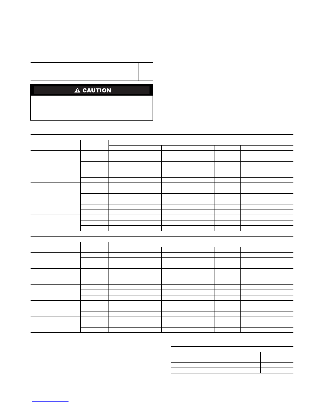
Make Duct Connections — If applicable, install all
ductwork to and from unit in accordance with all applicable
codes. Duct construction must allow unit to operate within duct
external static pressure limits as shown on job submittals and in
Tables 5 and 6. Duct opening should be the same size as the
unit. For units ducted to multiple openings, make sure there is
adequate straight duct, as shown below, immediately after the
unit.
40UH 075 100 125 150 200
Minimum Straight
Duct Required
(Length in ft)
Units designed to operate with ductwork may be damaged
if operated without intended ductwork attached.
Ensure that units ducted to multiple openings have sufficient
straight duct immediately after the unit.
FACTORY SETTINGS — CHILLED WATER COIL APPLICATIONS
Unit Speed
40UV050
40UV,UH075
40UV,UH100
40UV,UH125
40UV,UH150
45 52 58 63 75
Table 5 — Unit Ventilator Airflow — PSC Motor*
1-Row 2-Row 3-Row 4-Row 5-Row 6-Row 7-Row
Max 522 510 497 485 490 489 457
High 503 490 476 464 473 476 444
Low 458 449 440 425 452 455 430
Max 806 778 750 747 766 732 697
High 682 664 645 629 621 596 570
Low 569 554 539 527 533 514 495
Max 1064 1033 1001 1013 973 980 967
High 662 659 655 642 763 740 717
Low 530 519 507 503 498 501 504
Max 1295 1285 1215 1218 1239 1250 1175
High 899 930 876 865 852 846 846
Low 568 616 597 570 568 558 573
Max 1542 1480 1500 1484 1468 1482 1374
High 1071 1068 1065 1034 1033 1031 1013
Low 812 801 790 881 848 842 799
Units provided with outside air must utilize the low-
temperature safety switch to prevent coil freeze-up.
Insulate all ductwork as required. Use flexible connections
to minimize duct-to-unit alignment problems and noise transmission where specified.
Install ductwork, grilles, and plenums so that they do not
restrict access to filter.
Cut openings for supply and return air grilles, thermostats,
and switch plates where specified on job drawings. Be careful
not to cut wires, piping, or structural supports. Use a steel thermostat shield ring to protect drywall from thermostat wiring
where applicable.
Prevent dust and debris from settling in unit. If wall finish or
color is to be applied by spraying, cover all openings to
prevent spray from entering unit.
Approximate Air Delivery (Cfm)
FACTORY SETTINGS — ELECTRIC HEAT/DX COIL APPLICATIONS
Unit Speed
40UV050
40UV,UH075
40UV,UH100
40UV,UH125
40UV,UH150
LEGEND
CX — Chilled Water Applications
DX — Direct Expansion
HW — Hot Water
*Standard on sizes 050-150.
Max 522 510 497 485 490 489 457
High 503 490 476 464 452 455 430
Low 458 449 440 425 410 414 406
Max 806 778 750 747 766 732 697
High 682 664 645 629 621 596 570
Low 569 554 539 527 533 514 495
Max 1064 1033 1001 1013 973 980 967
High 794 788 782 773 857 834 810
Low 662 659 655 642 628 620 611
Max 1295 1285 1215 1218 1239 1250 1175
High 1055 1040 1024 995 1099 1091 1052
Low 738 767 732 719 987 986 964
Max 1542 1480 1500 1484 1468 1482 1374
High 1285 1257 1229 1248 1246 1239 1199
Low 934 928 922 901 1033 1031 1013
1-Row 2-Row 3-Row 4-Row 5-Row 6-Row 7-Row
Approximate Air Delivery (Cfm)
NOTE: Use the table below to determine the heating and cooling coil
combinations available with PSC Motor operation.
COOLING COIL
5RowsCW 1 or 2 rows N/A 3 elements
4RowsCW 3 rows 1 or 2 rows 4 elements
3RowsCWorDX† 4rows 1or2rows 5or6elements
†DX cooling applications are only available in 3-row cooling
configurations.
HW Steam Electric
HEATING COIL
23
Page 24
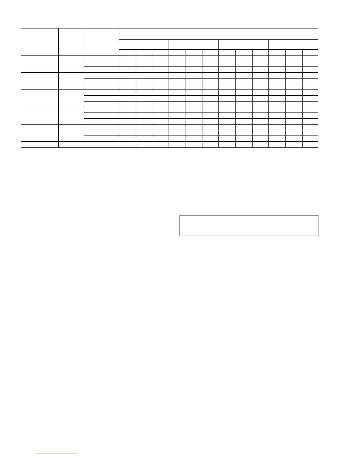
Table 6 — Unit Ventilator Airflow — ECM Airflow
UNIT SIZE
40UV050
40UV,UH075
40UV,UH100
40UV,UH125
40UV,UH150
40UH200
3-4EH/DX — Direct Expansion Coil Applications with 3 to
5-6EH — 5 to 6 Elements of Electric Heat
CW — Chilled Water Applications
ESP — External Static Pressure
MOTOR
HP
1
/
3
1
/
3
1
/
3
1
/
2
1
/
2
3
/
4
LEGEND
4 Elements of Electric Heat
COIL TYPE
3-4EH/DX 499 419 336 — — — — — — — — —
3-4EH/DX 747 644 498 753 609 472 752 612 470 751 618 498
3-4EH/DX 997 853 615 987 850 639 1012 823 626 994 819 618
3-4EH/DX 1266 1023 769 1239 1055 758 1235 1037 765 1231 1010 778
3-4EH/DX 1503 1246 956 1479 1216 965 1494 1209 927 1486 1222 917
CW 499 336 248 — — — — — — — — —
5-6EH 491 380 324 — — — — — — — — —
CW 747 484 346 753 548 432 752 530 437 751 541 386
5-6EH 755 645 583 746 598 539 755 585 554 765 610 542
CW 997 703 505 987 693 543 1012 663 483 994 692 480
5-6EH 1016 819 719 1002 851 709 1024 798 787 1024 820 734
CW 1266 880 657 1239 905 609 1235 898 676 1231 898 627
5-6EH 1259 1049 897 1239 995 888 1226 995 888 1253 994 919
CW 1503 1033 775 1479 1046 712 1494 1020 770 1486 1075 737
5-6EH 1517 1222 1068 1490 1206 1087 1498 1159 1120 1503 1188 1074
ALL 2014 1384 1023 1981 1386 971 1965 1385 997 1814 1354 993
APPROXIMATE AIR DELIVERY (Cfm)
ESP Speed Board Position
Low Position
(0.0 in. wg)
Max High Low Max High Low Max High Low Max High Low
Med Position
(0.10 in. wg)
NOTES:
1. Factory default is Low Position.
2. Med, High, and Max positions are field settings.
High Position
(0.25 in. wg)
Max Position
(0.45 in. wg)
Make Final Preparations
1. Turn power off (lock out and tag electrical disconnect).
2. Install thermostats and perform any other final wiring as
applicable.
3. Clean dirt, dust, and other construction debris from unit
interior. Be sure to check fan wheel and housing.
4. Rotate fan wheel by hand to be sure it is free and does not
rub on housing.
5. Be sure drain line is clear and is properly and securely
positioned. Pour water into drain to check operation.
6. Vent all air from unit coil and related piping. If air vent is
manual, release air from system by turning air vent screw
1
1
/2turns counterclockwise with screwdriver. When
steady stream of water begins to escape, close valve. If air
vent is automatic, trapped air will be vented automatically. Vent releases air slowly, usually dripping water into
drain pan in the process.
Make sure all service valves are open and that motorized
control valves, if supplied, are set for automatic operation.
7. Check all control valves in the system for proper operation in accordance with valve manufacturer’s instructions.
8. For units with factory-installed balancing valves, adjust
as follows:
a. Butterfly valves — Turn valve gate by inserting
screwdriverintoslotinvalvetopandrotatingupto
90 degrees. Valve is fully open when slot is parallel
with valve body. When slot is perpendicular to
body, flow through valve is at minimum. Valve
does not seal against flow.
b. Ball valves with lever handles — Valve gate action
is similar to butterfly valves above except that
when handle is perpendicular to valve body, there
is no flow through valve. Ball valves may be used
as shutoff valves.
9. Install filter in frame at front of coil. If field-supplied
filters are used, be sure size is correct. See Table 1 for
filter data.
10. Ensure all panels and filters are installed before checking
fan operation. Turn on unit power. Check fan and motor
operation.
.
IMPORTANT: Do not start up or operate unit without
filter and panels installed. Be sure filter and unit interior
are clean.
PRODUCT INTEGRATED CONTROL
Physical Characteristics —
tion of factory-supplied and factory-installed sensors, switches,
and devices (standard and optional). Tables 7-11 summarize
the Unit Ventilator Comfort Control module offerings and
accessory packages.
The control includes the electronic control board assembly,
fuses, relay, transformer, terminal block, low-limit air temperature protection (water coil units only), and other devices. A
disconnect switch, located below the control box, is provided
to shut off the power to the control box (see Fig. 10). See
Tables 8 and 9 for factory-installed options and accessory
packages.
Control environmental limitations are as follows:
Shipping Temperature -40 to 185 F
Shipping Humidity 10 to 95%
Operating Temperature 32 to 140 F
OperatingHumidity 10to90%
The Unit Ventilator Comfort Control module is powered from
the same source as the unit’s single source power connection.
Field wiring for accessories terminates in the control enclosure. Control accessory wiring requirements are 18 or 20 gage,
2 or 3 conductor twisted as specified. Refer to wiring details for
more information. See Table 10 for control board terminal
designations.
Carrier’s 40UV,UH unit ventilators with factory-installed
controls are ETL listed and listed to UL standard 1995 for heating and cooling equipment. All listings are for the complete
unit and all factory-supplied accessories. Use of other accessory components are not covered under these listings.
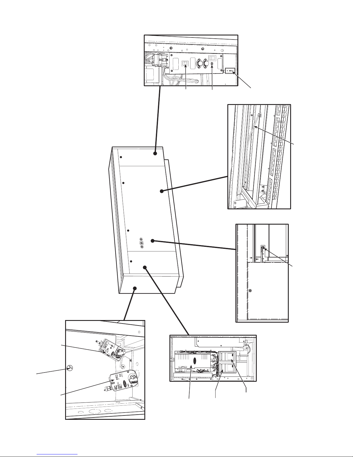
Figure 9 shows the loca-
24
Page 25
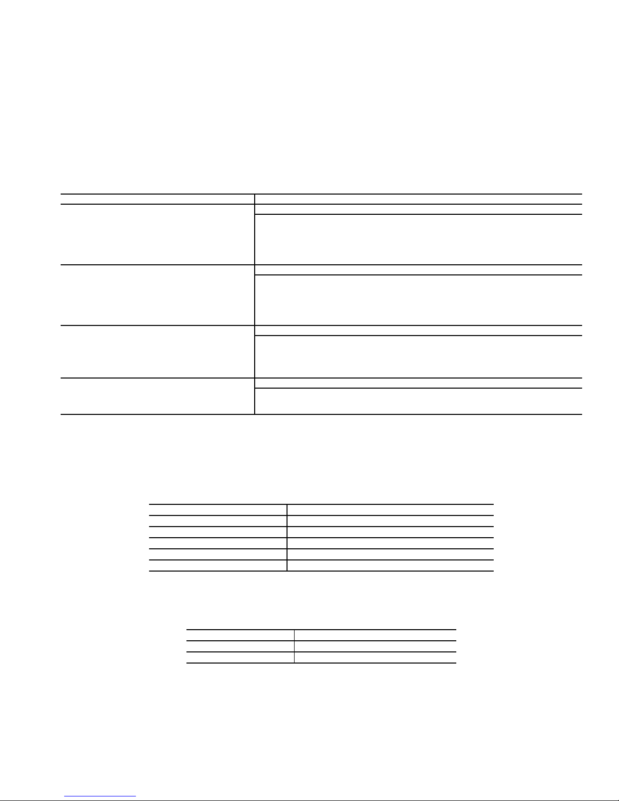
Table 7 — Standard Control Offerings
All control offerings provide the following features:
1. A 3-speed automatic fan control that minimizes fan noise by
matching the fan speed to the load. This process provides
better dehumidification during cooling and reduces energy
consumption.
2. American Society of Heating, Refrigeration and Air Conditioning
Engineers (ASHRAE) Cycle I, Cycle II, or Cycle III damper control options (Cycle II default).
3. Configurable minimum ventilation set point (cfm) for ASHRAE
Cycle II or Cycle III damper control.
4. Demand controlled ventilation with optional sensor to meet ventilation requirements with improved efficiency.
5. Coil freeze protection on all units except non-water units.
6. Proportional Integrated Derivative (PID) logic heating, cooling
and damper controls to maintain temperature.
7. Adjustable filter maintenance timer on all units.
8. Direct shaft coupled, electric actuators on all dampers. Spring
return on outdoor-air (OA) damper.
9. Spring return modulating water valves.
10. Optional relative humidity sensor for high humidity control or
dehumidification.
11. Optional remote-mounted space sensor with set point adjustment, tenant override, and service port jack.
12. Optional linkage thermostat with time clock, set point adjustment, schedule and holiday programming, digital temperature,
set point and equipment status display.
CONTROL SEQUENCE APPLICATION
2A/3A Chilled Water/Hot Water, 2-Pipe Changeover
2B/3B Chilled Water/Hot Water or Steam, 4-Pipe
2D/3D Chilled Water with Electric Heat
2F/3F Hot Water or Steam Heating Only
2G/3G Hot Water or Steam with DX Cooling
2J/3J Chilled Water Cooling Only
20/30 Chilled Water/Hot Water, 2-Pipe Changeover
21/31 Chilled Water/Hot Water or Steam, 4-Pipe
22/32 Chilled Water with Electric Heat
23/33 Hot Water or Steam with DX Cooling
24/34 Hot Water or Steam Heating Only
25/35 Chilled Water Cooling Only
2M/3M F&B Chilled Water/Hot Water or Steam Heating 4-Pipe plus Valve Control Reheat for
2G/3G Cooling with Hot Water or Steam Reheat, Valve Control
2B/3B Chilled Water/Hot Water Reheat, 4-Pipe Valve Control
2K/3K F&B Chilled Water Cooling with Hot Water or Steam Valve Control Reheat, 4-Pipe
LEGEND
DX — Direct Expansion
F&B — Face and Bypass
Heating/Cooling Valve Control
Heating/Cooling with Face and Bypass Damper Control
Heating/Cooling with Humidity Control
Dehumidification
OC Electric Heat Only
OE Electric Heat with DX Cooling
OH DX Cooling Only
Non-Water Systems
Table 8 — Field-Installed Accessories
PACKAGE NO. PACKAGE DESCRIPTION
33CSKITLST-01 Programmable Linkage Thermostat with Timeclock
CGCDXSEN001A00 Wall-Mounted CO
CGCDXSEN002A00 Wall-Mounted CO
CGCDXGAS001A00 CO
HL39ZZ003 Wall-Mounted Relative Humidity Sensor
DIGIT #15 (2,S,M,4,V) Space Temperature Sensor
DIGIT #15 (1,0,R,3) Changeover Switch
Sensor (No Display)
2
Sensor with Display
2
Sensor Calibration Service Kit
2
Table 9 — Factory-Installed Options
CODE DESCRIPTION
25
Page 26
ON
OFF
SERVICE
SWITCH
HI
LOW
MAX
FAN SPEED
SWITCH
DISCONNECT
SWITCH
MIXED AIR TEMPERATURE SENSOR
(UNIT FILTER REMOVED)
o
r
S
a
1
b
l
5
S
u
24V
(
2
2
y
A
.
e
5
S
C
l
)
(
A
3
CC
/
C
DC
O
W
M
b
)
l
k
0
1
C
+
C
re
W
3
C
3
d
2
W
S2
V
5
A2W
0/60
2
+
b
w
y
4
M
S
h
V
Be
a
H
1
A
t
3
d
.
H
5
e
l
1
C
C
i
F2
S3S
m
l
z
i
0
a
/
n
R
(
o
D
s
CW
TE
EG.
A
S
s
C
S
94D
u
w
2
M
LI
)
t
3
2
i
o
P
t
N
EQUI
S
S
z
.
S1
m
5
I
EM
e
T
BJ
N
u
a
r
P
E
ppl
D
t
l
.
i
a
D
A
.
o
y
&
n
2
n
d
0
U
3
L
9
C
W
8
L
0
3
R
C
.
M
5
9
.
C
.
1
2
1
i
W
n
8
0
0
-l
s
0
b
M
(4
Nm)
R
FACE AND BYPASS
DAMPER ACTUATOR
(MAY BE LOCATED ON OPPOSITE
ELECTRIC HEAT
OVER TEMPERATURE
SAFETY (ELECTRIC HEAT ONLY) SWITCH
OUTDOOR AIR
END OF COMPARTMENT)
DAMPER ACTUATOR
1
L
9
I
R
S
4
E
D
T
5
G
E
D
.
E
Q
U
I
U
L
ROOM-AIR TEMPERATURE
SENSOR
Fig. 9 — Typical Unit Ventilator Comfort Control Module Sensor, Switch, and Device Locations
H
F
M
2
3
B
J
0
4
n
0
~
R
~
~
CONTROL COMPARTMENT
LEGEND
OPTIONS SHOWN
WITH FACTORY-INSTALLED
DAMPER ACTUATOR(S)
RELATIVE
HUMIDITY
SENSOR
OPTION
(FIELD-
INSTALLED
ACCESSORY)
SPACE
TEMPERATURE
SENSOR
OPTION
(FACTORY-
INSTALLED
CONTROL
MODULE
OPTION)
ECM — Electronically Commutated Motor
LLT — Low-Limit Thermostat
26
Page 27
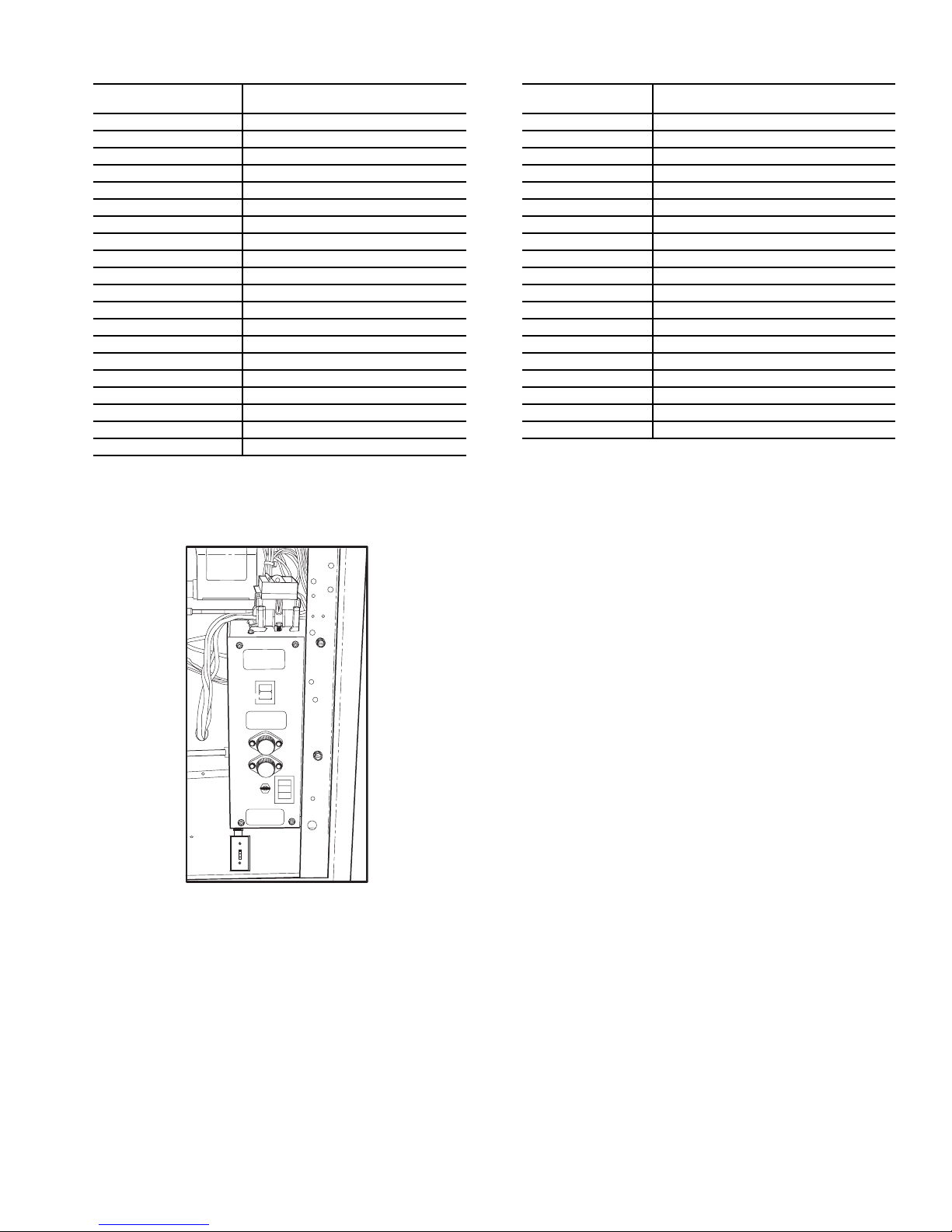
Table 10 — Control Board Terminal Designations
CONTROL BOARD
TERMINAL
T1 Space Temperature (+)
T2 Space Temperature (Gnd)
T3 Supply-Air Temperature (+)
T4 Supply-Air Temperature (Gnd)
T5 Mixed-Air Temperature (+)
T6 Mixed-Air Temperature (Gnd)
T7 Outdoor-Air Temperature (+)
T8 Outdoor-Air Temperature (Gnd)
T9 Space Temperature Adjust (+)
T10 Space Temperature Adjust (Gnd)
T11 Not Used
T12 Not Used
T13 Air Quality (+)
T14 Air Quality (Gnd)
T15 Relative Humidity (+)
T16 Relative Humidity (Gnd)
T17 Fa n S tatus
T18 Not Used
T19 Outdoor Air Enthalpy
T20 Remote Start/Stop
FUNCTION
CONTROL BOARD
TERMINAL
T21 Fire/Smoke Status
T22 Freezestat
T23 Changeover
T24 Spare
T25 Common/Ground
T26 24 VDC (External Power Supply)
T27 Not Available
T28 Cooling First Stage or Valve Open
T29 Cooling Common
T30 Cooling Second Stage or Valve Close
T31 Heating First Stage or Valve Open
T32 Heating Common
T33 Heating Second Stage or Valve Close
T34 OAD Open
T35 OAD Common
T36 OAD Close
T37 Heating Enable
T38 Common
T39 Cooling Enable
LEGEND
Gnd — Ground
OAD — Outdoor-Air Damper
FUNCTION
ON
OFF
MAX
HI
LOW
Fig. 10 — Control Switch Location
Unit Ventilator Comfort Control Module Installation and Field Wiring —
installed and factory-wired within the control compartment.
The Unit Ventilator Comfort Control module contains the software and microprocessor that operates the unit. It continuously
monitors inputs and controls outputs such as the fan cooling
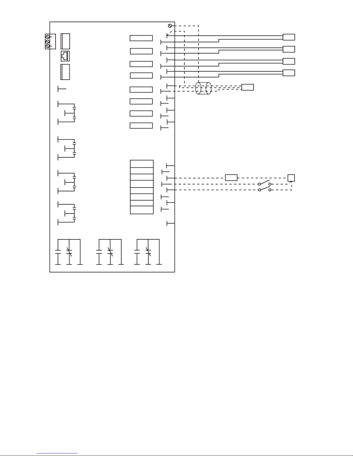
and heating coil valves and dampers. Refer to Fig. 11 for
wiring diagram connections between the unit’s sensors and
actuators and the control module. Direct expansion cooling
and/or electric heat stage control are also provided.
The module is factory-
27
Page 28
321
J1
POWER
J4
SERVICE CONNECTOR
321
J3
CCN
T26
24Vdc
T28
T29
COOLING
T31
T32
T35
T38
K3
HI/MED
OUTPUT
HEATING
OUTPUT
MIXED AIR
DAMPER
OUTPUT
HEATING
ENABLE
COOLING
ENABLE
T30
T33
T34
T36
T37
T39
FAN SPEED
ANALOG
SENSOR
INPUT
DISCRETE
SWITCH
INPUTS
K2
MED/LO
FAN SPEED
SPT/RAT
SAT
MAT
OAT
SPT ADJ
AQ
RH
FAN STATUS
OA ENTH
REMOTE
S/S
FIRE SMOKE
LOW LIMIT
CHANGEOVER
SPARE
COMMON
GND
K1
FAN ON/OFF
T2
T4
T6
T8
T10
T12
T14
T16
T18
T20
T22
T24
T1
T11
T13
T15
T17
T19
T21
T23
T25
T3
T5
T7
T9
ENT
SPT
OPTIONAL
WALL SENSOR
RAT
SAT
MAT
OAT
TB
NO
NC COM NO
NC
COM
NO NC
COM
LEGEND
ADJ — Adjust
AQ — Air Quality
CCN — Carrier Comfort Network® Controls
COM — Common
ENT — Enthalpy Sensor
GND — Ground
MAT — Mixed-Air Temperature Sensor
OA EN TH — Outdoor-Air Enthalpy
OAT —
NOTE: Only one SPT sensor can be used. If wall-mounted sensor option is used,
unit-mounted sensor wire to terminal T1 must be removed.
Outdoor-Air Temperature
Sensor
NC — Normally Closed
NO — Normally Open
RAT — Return-Air Temperature Sensor
S/S — Start/Stop
SAT — Supply-Air Temperature Sensor
SPT — Space Temperature Sensor
RH — Relative Humidity
TB — Terminal Block
Fig. 11 — Unit Ventilator Comfort Control Module with Sensor Connections
28
Page 29
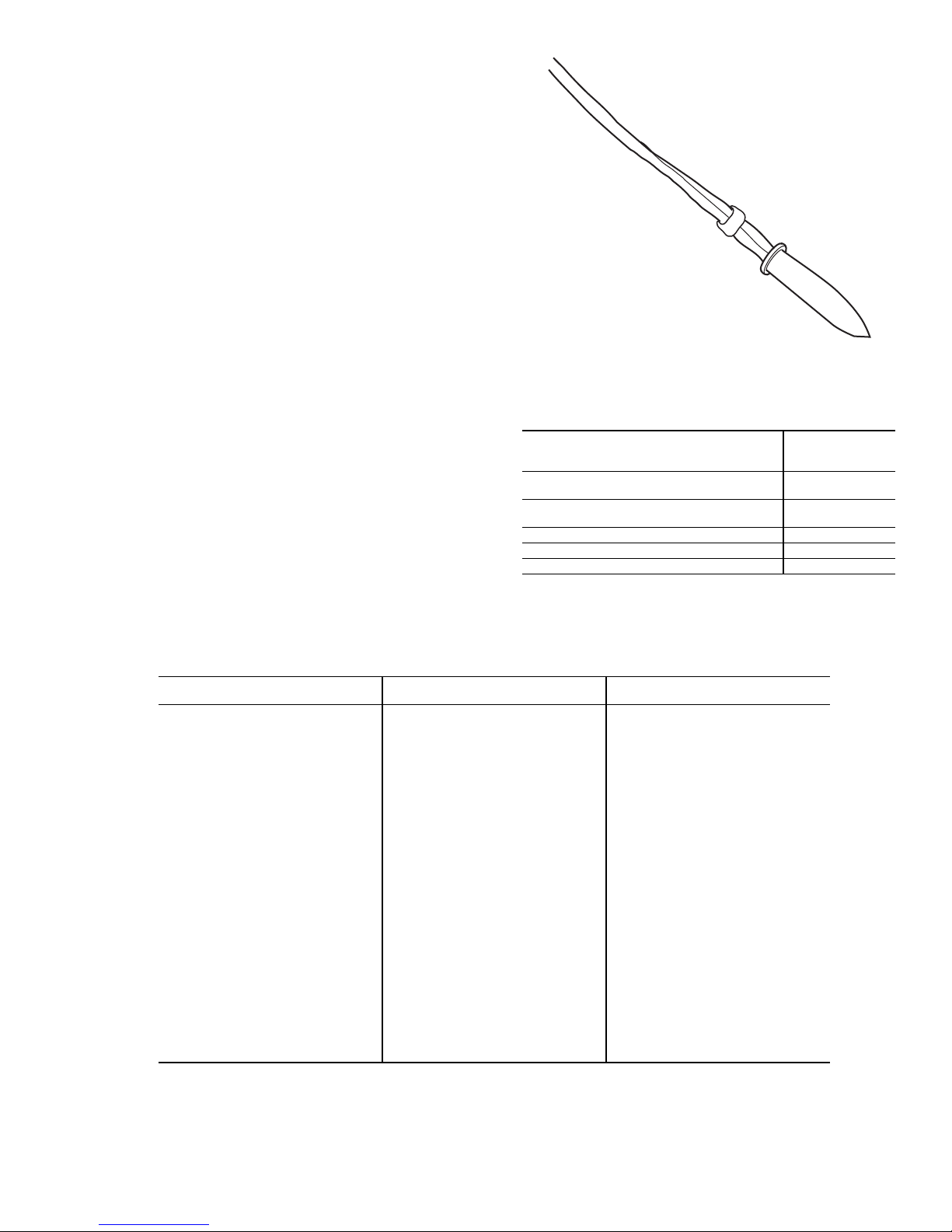
Sensors
ROOM-AIR TEMPERATURE (RAT) SENSOR — The RAT
sensor is factory-installed and factory-wired to the control. It
measures the temperature of the air returning to the unit from
the space.
The sensor consists of a thermistor, encased within an
epoxy bead. See Fig. 12. It is mounted behind the front center
panel, where it is hidden from view.
The sensor has a range of –40 to 245 F with a nominal
resistance of 10,000 ohms at 77 F. The sensor is connected to
terminals T1 and T2 on the controller board. See Table 11.
Polarity is not a consideration. See Table 10 for resistance vs
temperature values.
SUPPLY-AIR TEMPERATURE (SAT) SENSOR — The SAT
is factory-installed and factory-wired to the control module. It
measures the temperature of the air leaving the unit.
The sensor consists of a thermistor encased within an epoxy
bead. It is mounted in the fan discharge with the probe mounted to sense the air temperature supplied to the room. See
Fig. 12.
The sensor’s thermistor has a range of –40 to 245 F with a
nominal resistance of 10,000 ohms at 77 F.
NOTE: A temperature of the supply air includes fan heat.
In the control box, the sensor wires are connected to terminals T3 and T4 (SAT) on the controller board (see Table 11).
Polarity is not a consideration. See Table 12 for resistance vs
temperature values.
Fig. 12 — Room-Air Temperature and Supply-Air
Temperature Sensor (Part No. HN79NZ005)
Table 11 — Sensor Connections
SENSOR
Unit Mounted Room-Air Temperature
Sensor (RAT)
Space Temperature Sensor (SPT) Wall
Mount (Option)
Supply-Air Temperature (SAT) T3 and T4
Mixed-Air Temperature Sensor (MAT) T5 and T6
Outdoor-Air Temperature Sensor (OAT) T7 and T8
CONTROL
MODULE
PIN NO.
T1 and T2
T1, T9, T10, Shield
Table 12 — Thermistor Resistance vs Temperature Values for Room-Air Temperature Sensor,
Supply-Air Temperature Sensor, Mixed-Air Temperature Sensor,
and Optional Space Temperature Sensor
TEMP
(C)
–40 –40 335,651
–35 –31 242,195
–30 –22 176,683
–25 –13 130,243
–20 –4 96,974
–15 5 72,895
–10 14 55,298
–5 23 42,315
03232,651
54125,395
10 50 19,903
15 59 15,714
20 68 12,494
25 77 10,000
30 86 8,056
35 95 6,530
40 104 5,325
45 113 4,367
50 122 3,601
55 131 2,985
60 140 2,487
65 149 2,082
70 158 1,752
TEMP
(F)
RESISTANCE
(Ohms)
29
Page 30
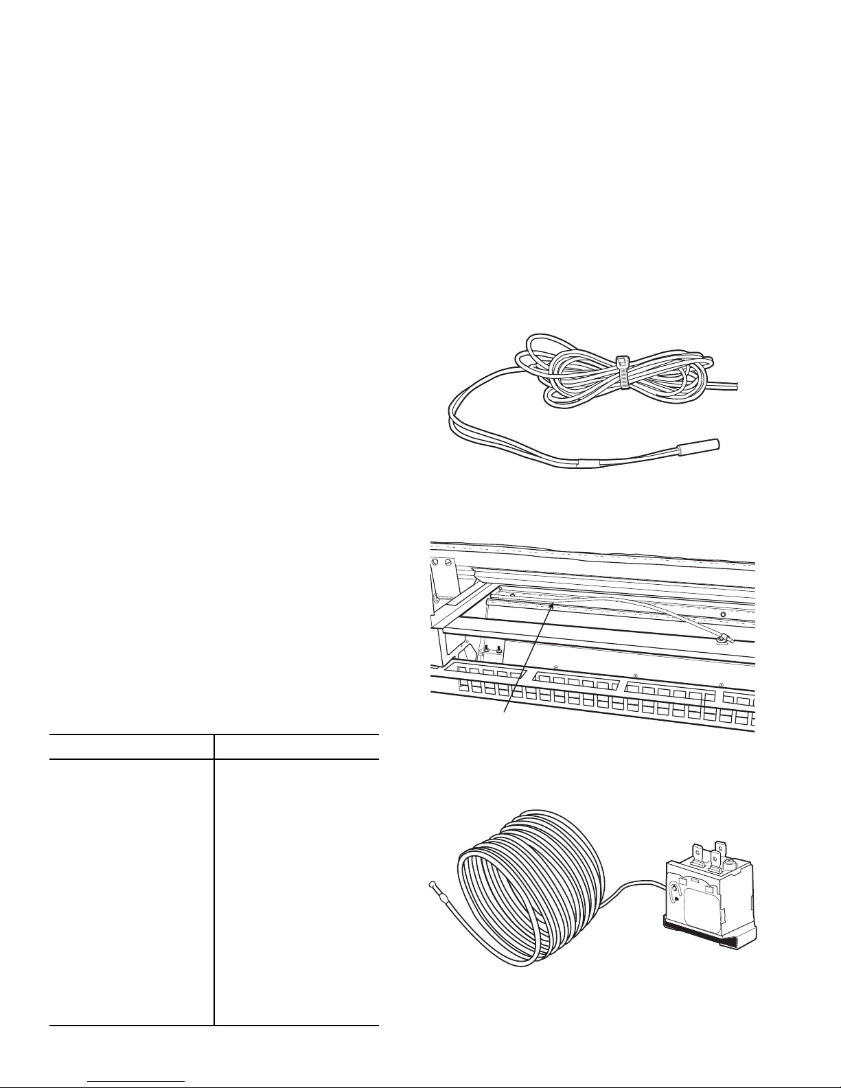
OUTDOOR-AIR TEMPERATURE (OAT) SENSOR — The
OAT sensor is factory-installed and factory-wired to the control. The OAT sensor monitors the temperature of the outside
air entering the unit. See Fig. 13.
The sensor is installed immediately upstream from the
outdoor-air damper where it will accurately sense the temperature of the outdoor air entering the mixing box. The sensor connects to the control module T7 and T8 (OAT) as shown in
Table 11.
The thermistor has a range of –40 to 245 F and a resistance
of 5,000 ohms at 77 F. See Table 13 for thermistor resistance
according to temperature value.
MIXED-AIR TEMPERATURE (MAT) SENSOR — The
mixed-air temperature (MAT) sensor is factory-supplied,
factory-installed, and factory-wired with each unit. The MAT
measures the temperature of air in the mixing plenum area.
The MAT connects to terminals T5 and T6 on the control module using
1
/4-in. female quick connect terminals. See
Table 11.
The sensor uses multiple thermistor elements. This sensor
provides both mechanical and electrical averaging to achieve
an accurate, average temperature measurement over the entire
element length. Polarity is not a consideration. See Table 12 for
resistance vs temperature values. The sensor is installed in the
mixing plenum before the filter so it can sense the average air
temperature. See Fig. 14.
The MAT has range of –40 to 245 F with a nominal resistance of 10,000 ohms at 77 F.
LOW-LIMIT THERMOSTAT — The low-limit thermostat
(LLT) is factory-installed and factory-wired on all units with
water coils. The thermostat is used to protect the water coils
from freezing temperatures in the event of a malfunction by
detecting the status of a potentially damaging condition.
The LLT is a 12-ft capillary tube mounted in the air stream.
See Fig. 15.
The LLT provides a SPDT contact. The contact provides a
sensor status indication to the control module and an electrical
interlock to the fan and water valves. Upon detection of a fault
condition, the unit ventilator will stop the fan, close the
outdoor-air damper, and position water valves as specified in
the sequence of operation. The LLT is factory set to trip at 38 F.
The temperature setting is non-adjustable. The switch will
automatically reset and restart the fan after its temperature has
risenbyatleast5°F.
Table 13 — Thermistor Resistance vs Temperature
Values for Outdoor-Air Temperature Sensor
RESISTANCE
(Ohms)
168,250.0 –40
121,350.0 –31
88,500.0 –22
65,200.0 –13
48,535.0 –4
36,476.0 5
27,665.0 14
21,165.0 23
16,325.0 32
12,695.0 41
9,950.0 50
6,245.0 68
5,000.0 77
4,028.5 86
3,265.0 95
2,663.3 104
2,185.0 113
1,801.5 122
1,493.0 131
1,244.0 140
1,041.5 149
876.0 158
739.5 167
627.5 176
TEMPERATURE
(F)
The LLT is designed to trip if any 1-ft section of the capillary tube senses cold air at or below the thermostat setting. The
temperature must exceed 43 F for the thermostat to automatically reset to restore the circuit to normal operation.
REFRIGERANT LOW-LIMIT THERMOSTAT — The refrigerant low limit thermostat (LLR) is factory-installed and
factory-wired on all units with direct expansion coils. The thermostat is used to protect the water coils from freezing temperatures in the event of a malfunction by detecting the status of a
potentially damaging condition.
The LLR is a 18 in. capillary tube mounted in the air stream.
See Fig. 15.
The LLR provides a SPDT contact. The normally closed
contact is connected in series with the direct expansion relay
coil, such that the DX (direct expansion) control relay is
deenergized in a fault condition. The LLR is factory set to trip
at 28 F. The temperature setting is non-adjustable. The switch
will automatically reset and allow direct expansion relay operation when the temperature has risen by at least 5° F.
Fig. 13 — Outdoor-Air Temperature Sensor
(Part No. HH79NZ055)
MIXED-AIR
TEMPERATURE SENSOR
Fig. 14 — Mixed-Air Temperature Sensor Installed
in Mixing Plenum (Part No. HH79NZ075)
Fig. 15 — Low-Limit Thermostat
30
Page 31
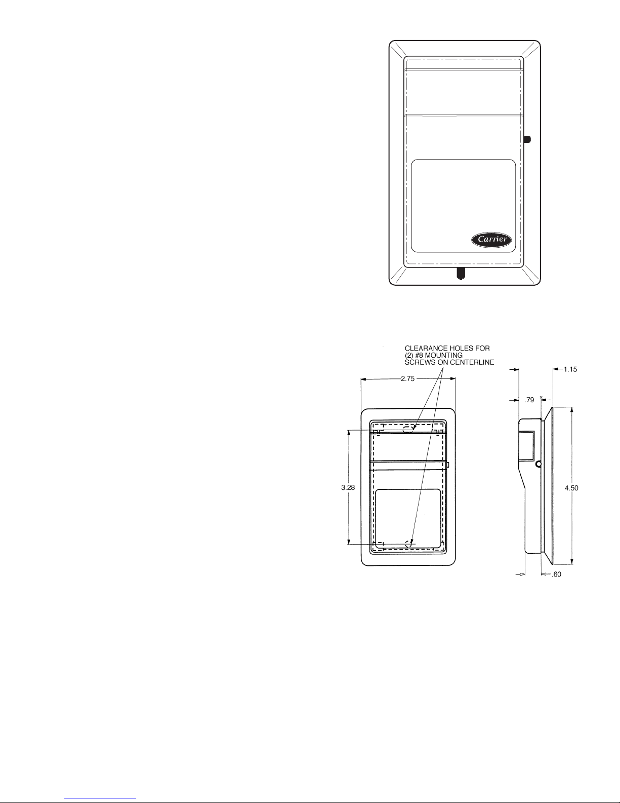
The LLR is designed to trip if any 1-ft section of the capitally tube senses cold air below the LLR set point. The temperature must exceed 33 F for the LLR to automatically reset to
restore normal operations.
SPACE TEMPERATURE SENSOR (Factory-Installed
Option) — The space temperature sensor is used to measure
the building interior temperature. See Fig. 16.
The sensor is shipped with the unit, factory-wired
and factory-mounted in the control swing panel inside the left
hand compartment.
If remote temperature sensing is required, then the sensor
may be removed and mounted on an internal wall where
temperature sensed is representative of the entire zone to be
serviced by the unit. The sensor wall plate accommodates the
National Electrical Manufacturers Association (NEMA)
standard 2 x 4 junction box. The sensor can be mounted directly on the wall surface if acceptable by local codes.
Do not mount the sensor in drafty locations (such as near
air-conditioning or heating ducts), over heat sources (such as
baseboard heaters or radiators), or directly above wall-mounted
lighting dimmers. Do not mount the sensor near a window
which may be opened, near a wall corner, or near a door.
Sensors mounted in these areas will have inaccurate and erratic
sensor readings.
The sensor should be mounted approximately 5 ft from the
floor, in an area representing the average temperature in the
space. Allow at least 4 ft between the sensor and any corner
and mount the sensor at least 2 ft from an open doorway.
Install the sensor as follows (see Fig. 17):
1. Locate the two Allen head screws at the bottom of the
sensor.
2. Turn the two screws clockwise to release the cover from
the sensor wall mounting plate.
3. Lift the cover from the bottom and then release it from
the top fasteners.
4. Feed the wires from the electrical box through the opening in the center of the sensor mounting plate.
5. Usingtwono.6-32x1mounting screws (provided with
the sensor), secure the sensor to the electrical box.
6. Use a three-conductor 20 gage shielded cable. The wire is
suitable for distances of up to 500 ft. The standard CCN
(Carrier Comfort Network®) communication cable may
be used. If the set point adjustment (slide-bar) is not required, then an unshielded, 18 or 20 gage, two-conductor,
twisted pair cable may be used.
The CCN network service jack requires a separate,
shielded three-conductor CCN communication cable.
Always use separate cables for CCN communication and sensor wiring. (Refer to Fig. 18 for wire
designations.)
7. Replace the cover by inserting the cover at the top of the
mounting plate first, then swing the cover down over the
lower portion. Rotate the two Allen head screws counterclockwise until the cover is secured to the mounting plate
and locked in position.
For more sensor information see Table 12 for thermistor
resistance vs temperature values.
NOTE: Clean sensor with damp cloth only. Do not use
solvents.
Cool
Warm
Fig. 16 — Space Temperature Sensor
(P/N HH51BX005)
NOTE: Dimensions are in inches.
Fig. 17 — Space Temperature Sensor and
Wall-Mounted Humidity Sensor Mounting
31
Page 32

WIRING THE SPACE TEMPERATURE SENSOR AND
SET POINT ADJUSTMENT — To wire the sensor and
slidebar, perform the following (see Fig. 18):
1. Identify which cable is intended for sensor wiring.
2. Strip back the jacket from the cables at least 3 inches.
1
Strip
/4-in. of insulation from each conductor. Cut the
shield and drain wire from the sensor end of the cable.
3. Connect the sensor cable as follows:
a. Install a jumper between the two center terminals
(SEN and SET).
b. Remove the existing factory-connected wire on
terminal T1 of the control module.
c. Connect one wire from the cable (RED) to the T1
terminal on the controller. Connect the other end
of the wire to the SEN terminal without the
jumper wire.
d. Connect another wire from the cable (BLACK)to
the T10 terminal on the controller. Connect the
other end of the wire to the remaining jumpered
SEN terminal.
e. Connect the remaining wire (WHITE/CLR) to the
T9 terminal on the controller. Connect the other
end if the wire to the remaining open terminal on
the SET terminal block.
f. In the control box, install a no. 6 ring type crimp
lug on the shield drain wire. Install this lug under
the mounting screw in the upper right corner of
the controller (just above terminal T1).
WIRING THE CCN NETWORK COMMUNICATION
SERVICE JACK — To wire the service jack, perform the
following:
1. Strip back the jacket from the CCN communication cable(s) for at least 3 inches. Strip
1
/4-in. of insulation from
each conductor. Remove the shield and separate the drain
wire from the cable. Twist together all the shield drain
wires and fasten them together using a closed end crimp
lug or a wire nut. Tape off any exposed bare wire to prevent shorting.
2. Connect the CCN + signal wire(s) (RED) to Terminal 5.
3. Connect the CCN – signal wire(s) (BLACK)toTerminal 2.
4. Connect the CCN GND signal wire(s) (WHITE/CLR) to
Terminal 4. Before wiring the RJ11 plug refer to Carrier
Comfort Network® Interface, page 38 for communication bus wiring and cable selection. The cable selected
must be identical to the CCN communication bus wire
used for the entire network.
The other end of the communication bus cable must be
connected to the remainder of the CCN communication bus. If the cable is installed as a T-tap into the bus,
the cable length cannot exceed 100 ft. Wire the CCN
service jack of the sensor in a daisy chain arrangement
with other equipment. Refer to Carrier Comfort
Network Interface section, page 38 for more details.
LINKAGE THERMOSTAT (Field-Installed Accessory) —
The linkage thermostat can be used to control multiple units
(up to 8 different sizes and types) from a single thermostat,
provide occupancy scheduling for any number of units (all
operating on the same schedule), and broadcast the changeover
switch status (2-pipe systems) to all units in the system
(Fig. 19). The thermostat is equipped with two liquid crystal
displays (LCD). One LCD is used to display the set points,
space temperature, unit operating mode (Heating, Cooling, Off,
etc.), and discharge air temperature from the unit. The second
LCD displays the time and day of the week. The thermostat has
pushbutton keys to enter the temperature set points, program
the occupancy schedule, program holidays, set time, day, and
date, and configure the functionality of the device.
When the thermostat provides local occupancy and set point
scheduling for these units, it provides a Temperature Compensated Start feature which starts the unit(s) prior to the scheduled
occupied time in order for the space to achieve the occupied set
point temperature at the occupied time.
The thermostat uses CCN communications to provide the
required information exchange between the thermostat and the
unit’s controls.
The thermostat can be used to provide global occupancy
scheduling for any number of units when a CCN user interface
is not provided. In this mode, a 3-wire communication bus
connected between each unit and the thermostat allows a user
to program and change equipment occupancy scheduling and
holidays from a single location without requiring the use of a
personal computer. This allows any number of unit ventilators
equipped with the Unit Ventilator Comfort Control module to
operate to a common occupancy schedule (all controllers must
be connected to a single CCN communication bus). Each Unit
Ventilator Comfort Control module will use its own set points
and space temperature settings.
The linkage thermostat can broadcast the value of an equipment status point to all units connected to the communication
bus. The point name must be configured using a CCN Service
Tool at installation. A typical example is to broadcast the status
of the changeover switch (2-pipe systems) or a field-supplied
and field-installed outdoor-air enthalpy sensor from the one
unit where the sensor is installed to all other units. This action
reduces the installation cost and operating maintenance of the
entire system.
When used to provide Global Occupancy Scheduling or
Broadcast, the thermostat does NOT need to be mounted in any
specific space. The thermostat can be mounted anywhere in a
conditioned area as long it is connected to the CCN communication bus.
The linkage feature allows several units to operate from a
single common thermostat. This feature can be used if multiple
units serve a single common area. The thermostat must be
mounted in the common area space for this feature.
Thermostat Mounting Location
— DO NOT mount the sensor in drafty locations (such as near air conditioning or heating
ducts), over heat sources (such as baseboard heaters or radiators), or directly above wall mounted-lighting dimmers. DO
NOT mount the sensor near a window which may be opened,
near a wall corner, or near a door.
Sensors mounted in these areas will have inaccurate and
erratic sensor readings. The sensor should be mounted approximately 5 ft from the floor, in an area representing the average
temperature in the space. Allow at least 4 ft between the sensor
and any corner and mount the sensor at least 2 ft from an open
doorway. Follow the mounting and wiring instructions included with the thermostat for proper thermostat installation.
32
Page 33
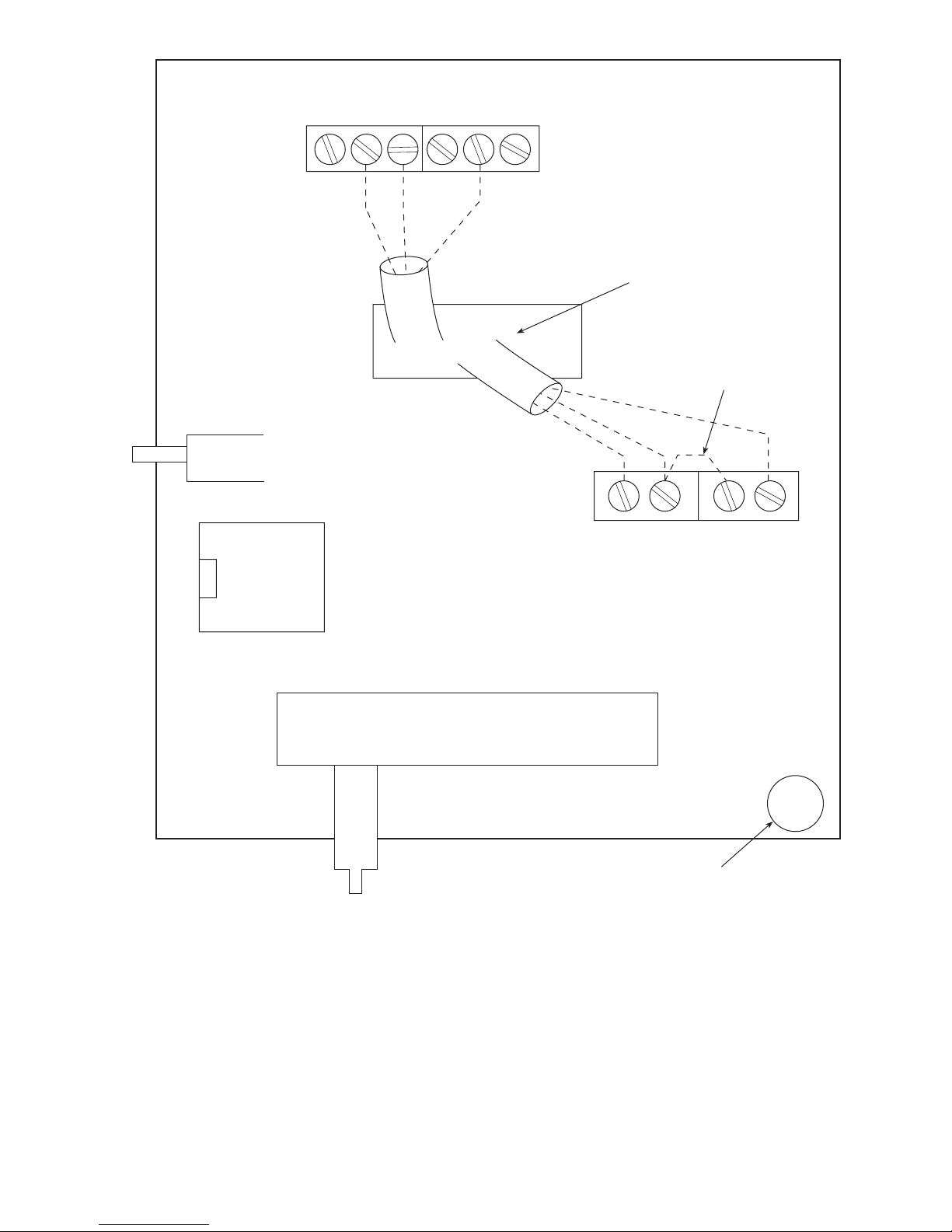
6
RED (+)
SENSOR PC
3
4
5
WHT (GND)
2
BLK (-)
1
BOARD
OVERRIDE
PUSHBUTTON
CCN
SERVICE
CONNECTOR
CCN
CABLE
SENSOR
CABLE
WHT (SW)
WIRE ACCESS
HOLE
RED (TH)
BLK (COM)
SET
JUMPER TERMINALS
AS SHOWN
SEN
LEGEND
CCN — Carrier Comfort Network®
COM — Common
GND — Ground
SET POINT
ADJUSTMENT
THERMISTOR TEMPERATURE
SENSOR
Fig. 18 — Space Temperature Sensor Wiring
33
Page 34
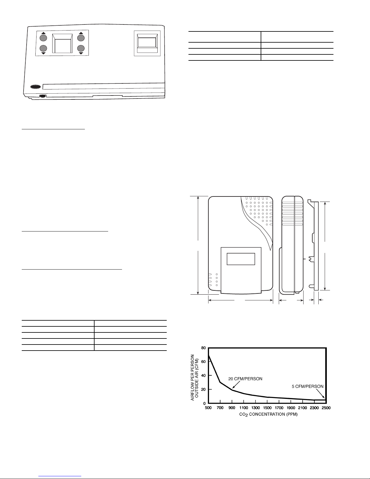
COOL
HEAT
Table 15 — Indoor Air Quality Sensor Accessories
CO2SENSOR ACCESSORY
PA RT N U MB ER S
CGCDXSEN001A00 Wall Mount Sensor (No Display)
CGCDXSEN002A00 Wall Mount Sensor with Display
CGCDXGAS001A00 Sensor Calibration Service Kit
DESCRIPTION
Carrier
®
Fig. 19 — Linkage Thermostat
Thermostat Power Supply
— The thermostat power supply,
included in the accessory package, provides the required
DC voltage to operate the thermostat. The power supply
includes 24 vac (Class II) transformer.
The transformer and power supply can be mounted within
the unit’s control enclosure.
Wiring between the thermostat and the power supply is
limited to 100 ft maximum. If longer distances are required, the
power supply and transformer must be remotely mounted
closer to the thermostat. Be sure to follow all code requirements when remotely mounting the transformer as the primary
wiring is Class I circuit type. The thermostat power wiring
requires the use of a 2-conductor, 18 AWG, twisted pair cable
to connect the power supply output terminals to the thermostat.
Follow the installation instructions shipped with the thermostat
for proper installation.
Thermostat Communication Wiring
— The thermostat uses
CCN network communications to exchange data between the
thermostat and the equipment control or the CCN network for
system functions. Use 3-conductor, 20 AWG (American Wire
Gage) minimum, shielded cable as specified in the Carrier
Comfort Network® Interface section. See Table 14.
Thermostat Remote Room Sensor Option
—Theinstaller
has the option of mounting the thermostat in a mechanical
closet or other location in order to limit access to the device. A
remote sensor option can be installed in the space to properly
sense temperature at the occupied location. Refer to the installation instructions shipped with the thermostat for additional
information on this option.
Table 14 — CCN Cable Requirements
MANUFACTURER CABLE NO.
Alpha 2413 or 5463
American A22503
Belden 8772
Columbia 02525
The CO
sensors in Table 15 are all factory set for a range of
2
0 to 2000 ppm and a linear voltage output of 2 to 10 vdc.
Fig. 21 shows ventilation rates for various CO2set points when
a typical CO
tions supplied with the CO
level of 350 ppm is used. Refer to the instruc-
2
sensor for electrical requirements
2
and terminal locations. A separate isolated field-supplied transformer is required to provide power to the sensor.
Any changes to the factory configuration of the sensor
require use of the User Interface Program (UIP), which is
included in the sensor calibration service kit.
The sensor must be properly located to accurately measure
the air quality of the occupied space. It should be mounted in a
location that will avoid direct breath contact.
Do not mount the sensor in drafty areas such as near the unit
discharge, open windows, fans, or over heat sources. Allow at
least 3 ft between the sensor and any corner. Avoid mounting
the sensor where it is influenced by the supply air; the sensor
gives inaccurate readings if supply air is blown directly onto
the sensor.
5.625
(14.3)
3.25
(8.3)
NOTE: Dimensions are in inches.
Dimensions in ()are in centimeters.
1.125
(2.9)
5
(12.7)
0.25
(0.8)
Fig. 20 — Indoor Air Quality (CO2) Sensor
(PN 33ZCSENCO2)
INDOOR AIR QUALITY (IAQ) SENSOR (Field-Installed
Accessory) — The wall-mounted sensor monitors CO
conditioned air space, and uses infrared technology to detect
the levels of CO
present in the air. See Fig. 20. This informa-
2
tion is used to modify the position of the outdoor-air dampers
to admit more outdoor air as required to provide the desired
ventilation rate. The sensor is available with or without an
LCD readout to display the CO
level in ppm. Sensor acces-
2
sory descriptions and part numbers are shown in Table 15. To
mount the sensor, refer to the installation instructions shipped
with the accessory kit.
in the
2
34
Fig. 21 — Ventilation Rates Based on
CO
Set Point
2
Page 35
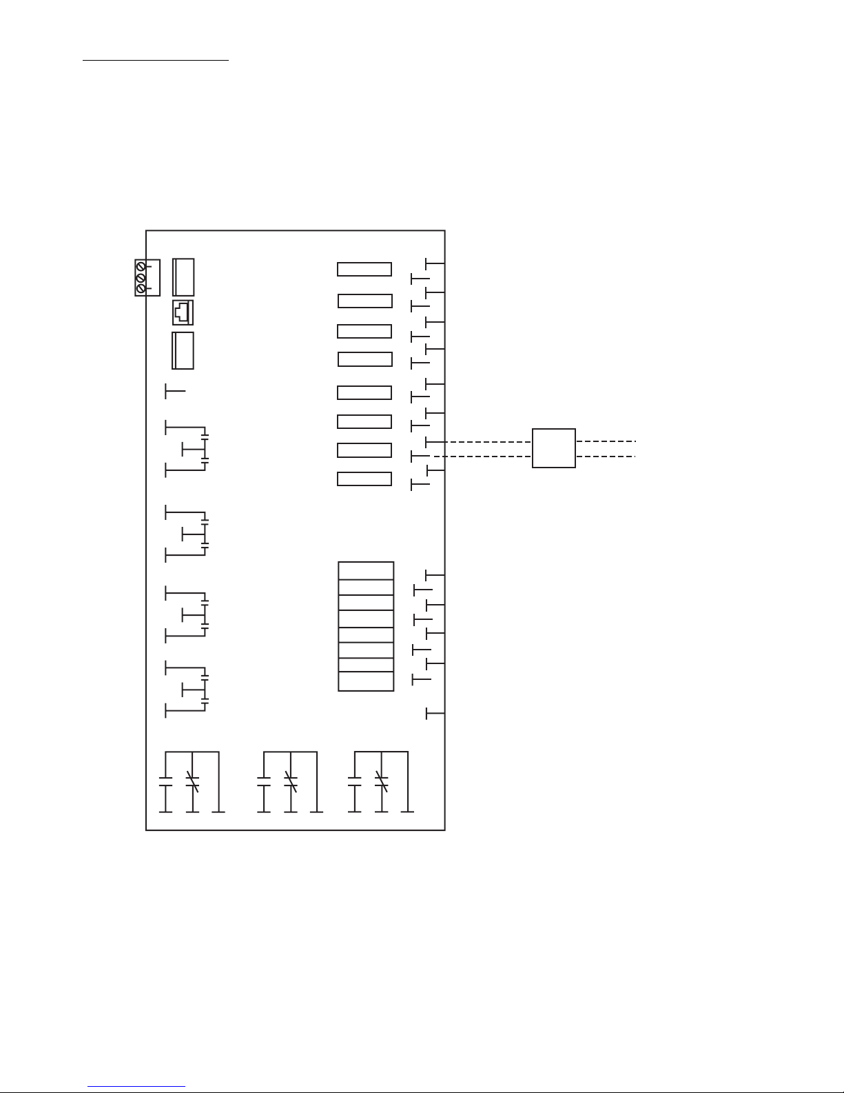
Air Quality Sensor Wiring
— To wire the sensor after it has
been mounted in the conditioned space, see Fig. 22 and the
installation instructions shipped with the sensor. For each
sensor, use 2-conductor 18 AWG twisted-pair cables
(unshielded) to connect the separate isolated 24 vac power
source to the sensor and to connect the sensor to the control
board terminals.
To connect the sensor to the control board, identify the
positive (+) and negative (–) output terminals to the sensor
terminal block and connect the positive terminal to terminal
T13. Connect the negative terminal to terminal T14 on the
control board. Mount a field-supplied Class II, 24 vac transformer with a 40 va rating in a suitable location inside the unit’s
control box. Wire the transformer primary to line voltage
power after any fuses and disconnect switches. Ensure the
transformer primary voltage rating matches the unit’s voltage
rating. Refer to the wire label diagram shipped with the unit.
Connect one of the transformer secondary leads to the 24 vac
power terminal of the sensor. Connect the remaining secondary
lead to the ground terminal sensor.
321
J1
POWER
J4
SERVICE CONNECTOR
321
J3
CCN
T26
24Vdc
T28
T29
COOLING
T32
T35
T38
K3
HI/MED
OUTPUT
HEATING
OUTPUT
MIXED AIR
DAMPER
OUTPUT
HEATING
ENABLE
COOLING
ENABLE
T30
T31
T33
T34
T36
T37
T39
FAN SPEED
ANALOG
SENSOR
INPUTS
DISCRETE
SWITCH
INPUTS
K2
MED/LO
FAN SPEED
SPT/RAT
SAT
MAT
OAT
SPT ADJ
AQ
RH
FAN STATUS
OA ENTH
REMOTE
S/S
FIRE SMOKE
LOW LIMIT
CHANGE OVER
SPARE
COMMON
GND
K1
FAN ON/OFF
T2
T4
T6
T8
T10
T12
T14
T16
T18
T20
T22
T24
T1
T3
T5
T7
T9
T11
T13
T15
T17
T19
T21
T23
T25
+
AQ
-
FIELD SUPPLIED
ISOLATED 24VAC
POWER SOURCE
NO
NC COM NO
ADJ — Adjust
AQ — Air Quality
CCN — Carrier Comfort Network®
COM — Common
GND — Ground
MAT — Mixed-Air Temperature Sensor
OA EN TH — Outdoor-Air Enthalpy
OAT — Outdoor-Air Temperature Sensor
COM
NC
NO NC
COM
LEGEND
NC — Normally Closed
NO — Normally Open
RAT — Return-Air Temperature Sensor
S/S — Start/Stop
SAT — Supply-Air Temperature Sensor
SPT — Space Temperature Sensor
RH — Relative Humidity
Fig. 22 — Air Quality Sensor Wiring
35
Page 36
RELATIVE HUMIDITY SENSOR (Field-Installed Accessory) — The relative humidity (RH) sensor is used to measure
the relative humidity of the air within the occupied space. The
sensor is ordered separately from the unit, is field-installed and
should be wired in the control compartment below the control
module. It may be mounted directly on an interior wall if
acceptable by local codes. See Fig. 23.
The sensor uses bulk polymer resistance technology, which
eliminates the effect of surface contamination and helps to
maintain sensor accuracy over a long period of time. It has a
long-term stability of less than 1% drift per year.
The relative humidity sensor has a range of 10 to 90% with
an accuracy of ±3% at 77 F. It generates a 2 to 10 vdc signal
which is sent to the controller.
If the sensor is installed directly on a wall surface, install the
humidity sensor using 2 screws and 2 hollow wall anchors
(field-supplied); do not overtighten screws. See Fig. 17. The
useofastandard2x4-in.electricalboxtoaccommodatethe
wiring is recommended for installation.
DO NOT touch the sensing element or clean with chemical
solvents; they can permanently damage the sensor.
The sensor must be mounted vertically on the wall. The
Carrier logo should be oriented correctly when the sensor is
properly mounted.
DO NOT mount the sensor in drafty areas such as near the
unit’s discharge grille, open windows or fans, or over heat
sources such as baseboard heaters, radiators, or wall-mounted
light dimmers. Sensors mounted in those areas will produce
inaccurate readings.
Avoid corner locations. Allow at least 4 ft between the
sensor and any corner. Airflow near corners tends to be
reduced, resulting in erratic sensor readings.
Sensor should be vertically mounted approximately 5 ft up
from the floor.
For distances up to 500 feet, use a 3-conductor shielded,
20 AWG cable. A CCN communication cable can be used. The
shield and drain wire must be removed from the sensor end of
the cable. See Fig. 24 for wiring details.
The power for the sensor is provided by the control board.
The board provides 24 vdc for the sensor. No additional power
source is required.
To wire the sensor, perform the following:
1. At the sensor, remove 4-in. of jacket from the cable. Strip
1
/4-in. of insulation from each conductor. Route the cable
through the wire clearance opening in the center of the
sensor. See Fig. 24.
2. Connect the RED wire to the sensor screw terminal
marked (+).
3. Install one lead from the resistor (supplied with the sensor) and the WHITE wire, into the sensor screw terminal
marked (–). After tightening the screw terminal, test the
connection by pulling gently on the resistor lead.
4. Connect the remaining lead from the resistor to the
BLACK wire and secure using a closed end type crimp
connector or wire nut.
5. Using electrical tape, insulate any exposed resistor lead to
prevent shorting.
6. At the control end, remove the jacket from the cable and
route the RED conductor over to the left side of the control board. Route the remaining conductors to the right
side of the control board.
1
7. Strip
/4-in. of insulation from each conductor and equip
each with a1/4-in. female quick connect terminal.
8. Connect the RED wire to terminal T26 on the control
board.
9. Connect the BLACK wire to terminal T16 on the control
board.
10. Connect the WHITE/CLEAR wire to terminal T15 on the
control board.
11. Equip the shield wire with a no. 8 fork-type lug and
secure to the control module mounting screw between
terminals T16 and T17.
Fig. 23 — Wall-Mounted Relative Humidity Sensor
(Part No. HL39ZZ003)
36
Page 37
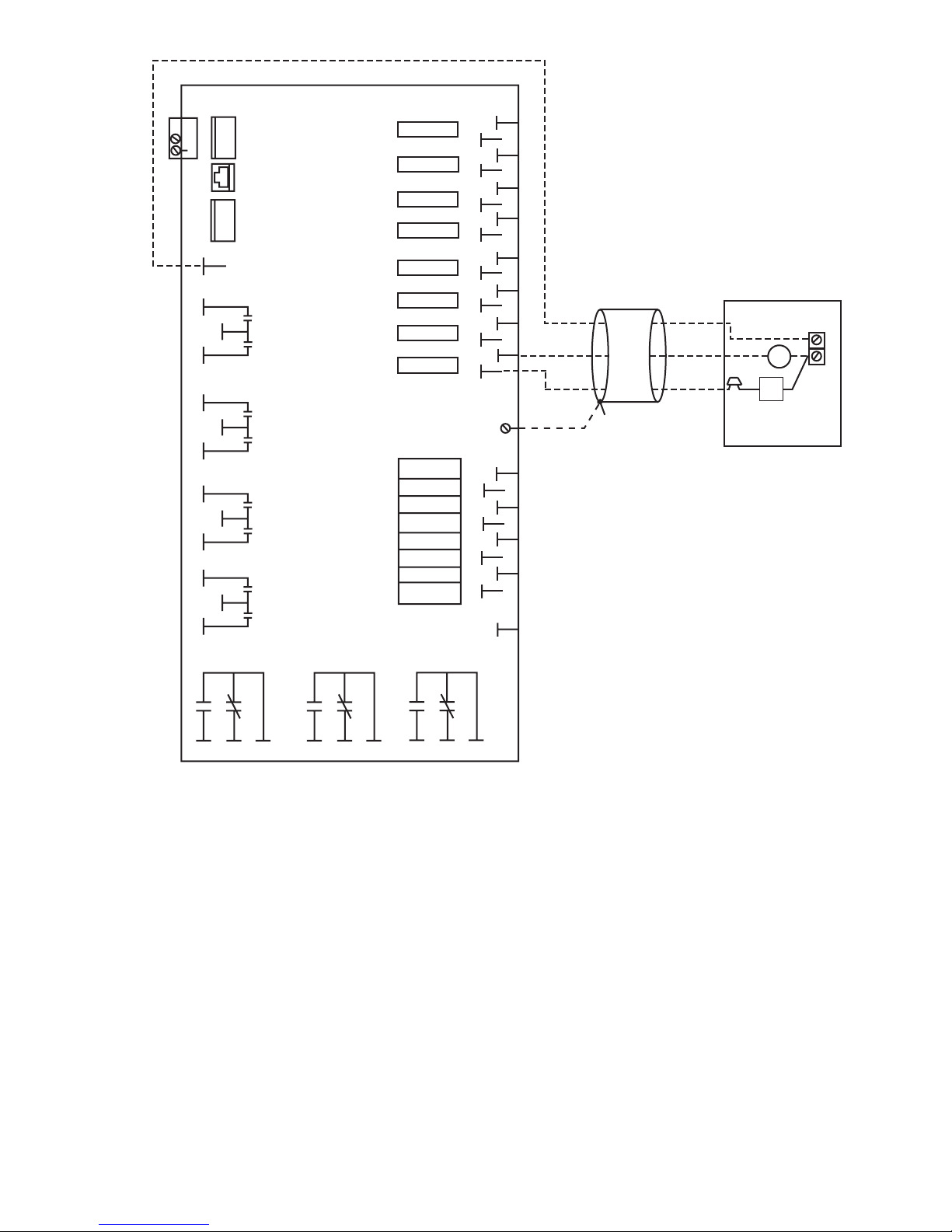
321
J1
POWER
J4
SERVICE CONNECTOR
321
J3
CCN
T26
24Vdc
T28
T29
COOLING
T32
T35
T38
K3
HI/MED
OUTPUT
HEATING
OUTPUT
MIXED AIR
DAMPER
OUTPUT
HEATING
ENABLE
COOLING
ENABLE
T30
T31
T33
T34
T36
T37
T39
FAN SPEED
ANALOG
SENSOR
INPUT
DISCRETE
SWITCH
INPUTS
K2
MED/LO
FAN SPEED
SPT/RAT
SAT
MAT
OAT
SPT ADJ
AQ
RH
FAN STATUS
OA ENTH
REMOTE
S/S
FIRE SMOKE
LOW LIMIT
CHANGE OVER
SPARE
COMMON
GND
K1
FAN ON/OFF
T2
T4
T6
T8
T10
T12
T14
T16
T18
T20
T22
T24
T1
T11
T13
T15
T17
T19
T21
T23
T25
T3
T5
T7
T9
RED
WHITE
BLACK
SHIELD
3 CONDUCTOR
20 AWG SHIELDED
CABLE
499
RESISTOR
(SUPPLIED
W/SENSOR)
HUMIDITY SENSOR
+
--
NO
NC COM NO
NC
COM
NO NC
ADJ — Adjust
AQ — Air Quality
CCN — Carrier Comfort Network®
COM — Common
GND — Ground
MAT — Mixed-Air Temperature Sensor
OA EN TH — Outdoor-Air Enthalpy
OAT — Outdoor-Air Temperature Sensor
Fig. 24 — Wiring of Relative Humidity Sensor to Control Board
COM
LEGEND
NC — Normally Closed
NO — Normally Open
RAT — Return-Air Temperature Sensor
S/S — Start/Stop
SAT — Supply-Air Temperature Sensor
SPT — Space Temperature Sensor
RH — Relative Humidity
37
Page 38
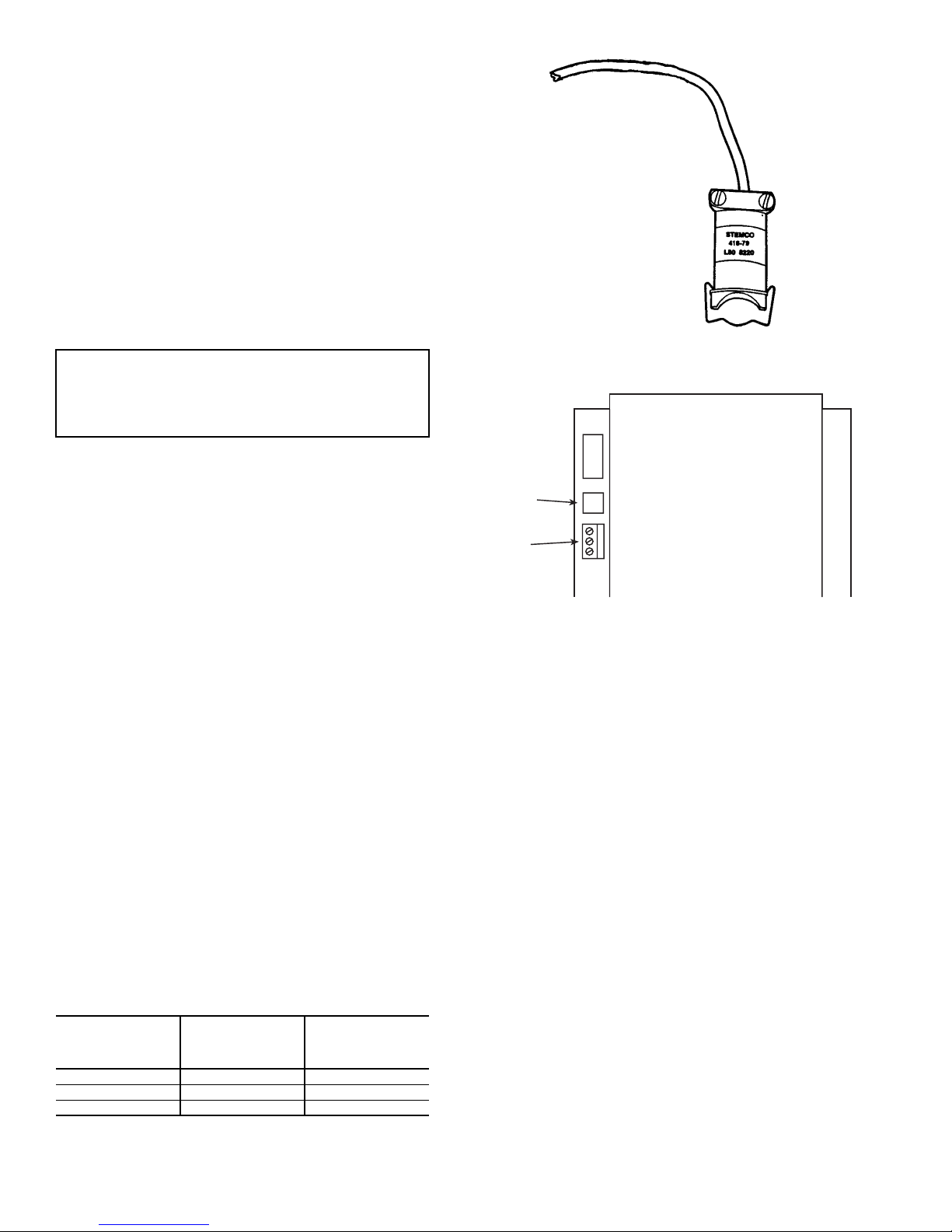
CHANGEOVER SWITCH (Factory-Installed Option) —
The changeover switch is used with 2-pipe changeover units to
determine if the temperature of the water in the water loop can
provide cooling or heating (Fig. 25). The switch provides this
input to the control. The changeover switch is factory-wired to
the control and ready for field mounting to the water piping.
The switch mounts to the water pipe using a spring-loaded
clamp.
It is primarily used for a stand-alone application, although
the changeover switch may be required for CCN applications if
the water temperature status is not available through the
network. For stand-alone applications, one switch is required
for each 2-pipe unit. If the units are connected together on a
3-wire CCN communication bus and a linkage thermostat
(or Unit Ventilator Comfort Control module [P/N 110500])is
used, then a single switch can be connected to any one unit and
the linkage thermostat can be configured to broadcast the
switch status to all other units.
IMPORTANT: The switch must be mounted on the
supply water pipe, where water flows continuously to
accurately sense the available water temperature. Never
mount the sensor on piping which is connected to a
2-way valve.
Fig. 25 — Changeover Switch
FILTER/SMOKE STATUS (CCN Systems Only) — The
filter/smoke status is monitored by the control module and
contains an adjustable alarm limit. The control accumulates
fan-operating hours; when the total hours exceed the limit, an
alarm is generated.
The alarm limit is adjustable from 100 to 9900 hours. It is
factory preset to 1500 operating hours. The limit is normally
field adjusted and is dependent on the filter media used as well
as the quality and amount of outdoor air required. The normal
range is from 400 to 1500 hours.
Carrier Comfort Network® Interface — The Carrier
Comfort Network (CCN) communication bus wiring is
supplied and installed by the electrical contractor. It consists of
shielded, 3-conductor cable with drain wire.
The system elements are connected to the communication
bus in a daisy-chain arrangement. The positive pin of each
system element communication connector must be wired to the
positive pins of the system element on either side of it; the
negative pins must be wired to the negative pins; the signal
ground pins must be wired to signal ground pins. See Fig. 26
for location of the CCN communication connector (NETWORK) on the control module.
NOTE: Conductors and drain wire must be 20 AWG minimum, stranded tinned copper. Individual conductors must be
insulated with PVC, PVC/nylon, vinyl, Teflon, or polyethylene. An aluminum/polyester 100% foil shield and an outer
jacket of PVC, PVC/nylon, chrome vinyl, or Teflon with a
minimum operating temperature range of –20 C to 60 C is
required. See Table 14 for cables that meet the requirements.
When connecting the CCN communication bus to a system
element, a color code system for the entire network is recommended to simplify installation and checkout. The following
color code is recommended:
SIGNAL
TYPE
+ RED 1
Ground WHITE 2
– BLACK 3
CCN BUS
CONDUCTOR
INSULATION
COLOR
CCN
CONNECTOR
POWER
RJ-14
SERVICE
JACK
CCN
CONNECTOR
SERVICE
NETWORK
Fig. 26 — CCN Communication Connector
If a cable with a different color scheme is selected, a similar
color code should be adopted for the entire network.
At each system element, the shields of its communication
bus cables must be tied together. If the communication bus is
entirely within one building, the resulting continuous shield
must be connected to ground at only one point. See Fig. 27. If
the communication bus cable exits from one building and enters another, the shields must be connected to ground at the
lightning suppressor in each building where the cable enters or
exits the building (one point only).
To connect the control to the network, proceed as follows
(Fig. 27):
1. Turn power to the control box OFF.
2. Remove the CCN connector from the control board.
3. Cut the CCN wire and strip the ends of the RED,
WHITE, and BLACK conductors.
4. Using a wire nut, connect the 2 drain wires together.
5. Insert and secure the 2 RED wires to terminal 1 of the
CCN connector.
6. Insert and secure the 2 WHITE wires to terminal 2 of the
CCN connector.
7. Insert and secure the 2 BLACK wires to terminal 3 of the
CCN connector.
8. Replace connector on control board.
9. Turn on power to control box.
38
Page 39
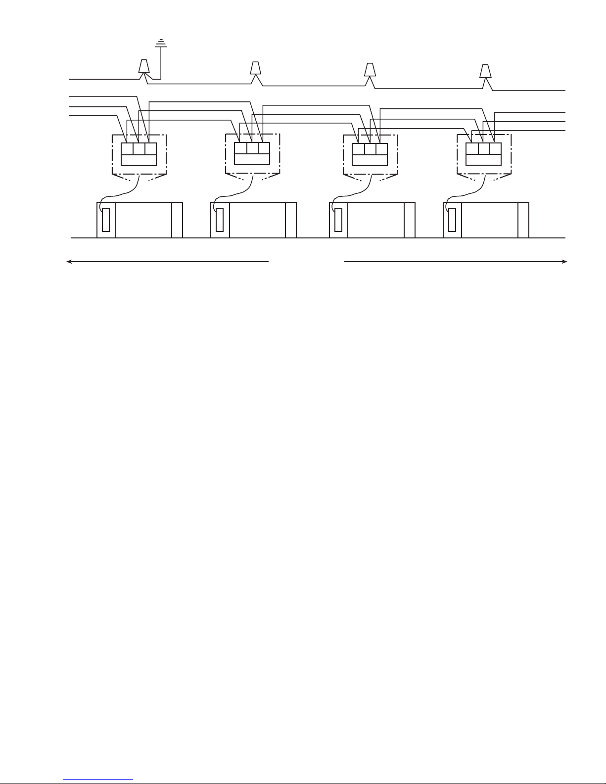
GROUND
DRAIN WIRE
BLACK
WHITE
RED
1
CCN
CONNECTOR
LEGEND
CCN — Carrier Comfort Network
2
UNIT VENTILATOR
3
DRAIN WIRE
BLACK
WHITE
RED
CCN
CONNECTOR
1
2
3
UNIT VENTILATOR UNIT VENTILATOR UNIT VENTILATOR
1000 FT MAXIMUM
Fig. 27 — CCN Communication Wiring
Relays — The fan relays are an integral component of the
control board. The fan motor speed control uses three SPDT
relays. The control relays are shown in Fig. 24. See the following sections for a description of how the control relay is used
with each function.
FAN RELAY — The fan rela y (K
) is factory-wired and
1
factory-installed on all units. The relay interfaces with the
Electronically Commutated Motor (ECM) motor control
circuit and automatically starts and stops the fan.
FAN SPEED RELAYS — The fan speed relays, K
and K3,
2
select the operating speed of the fan (High/Medium/Low). The
fan speed relays are factory-wired and factory-installed. These
relays control the speed of the motor.
Actuators
MODULATING OUTDOOR-AIR DAMPER ACTUATOR
(Fig. 28) — The outdoor-air damper actuator is factorysupplied and factory-installed directly on the damper jackshaft.
All wiring between the actuator and the control is provided by
the factory. The actuator is mounted so that the spring return
will close the outdoor-air damper and open the return-air
damper on loss of power.
The actuator consists of an electronically controlled reversible motor equipped with a microprocessor drive. The damper
actuator is supplied with approximately 8 ft of plenum rated
cable.
The actuator is capable of holding its position at any point in
the stroke and moving the damper in either direction.
The actuator is powered by the fused 24 vac transformer
located in the control box.
DRAIN WIRE
BLACK
WHITE
RED
CCN
CONNECTOR
DRAIN WIRE
BLACK
WHITE
RED
1
1
2
3
CCN
CONNECTOR
2
DRAIN WIRE
BLACK
WHITE
RED
3
FACE AND BYPASS DAMPER ACTUATOR (Fig. 29) —
The actuator provides 35 in.-lb torque rating and is powered by
the 24-vac transformer located in the control box.
Face and bypass dampers are factory-supplied and factoryinstalled on all face and bypass damper applications. These
actuators are proportional modulating, direct shaft mount type,
capable of being driven in either direction and holding position
at any point in the travel range.
The actuators are supplied with plenum rated cable.
Actuator connections depend on the application. Refer
to Application Data manual and wire label diagram for wiring
information.
The actuator is equipped with a SPDT damper end switch,
which senses when the damper is in the full bypass position.
The switch position is adjusted so that the switch closes
when the damper moves about 5 degrees from the full bypass
position.
FIELD-SUPPLIED TWO-POSITION RELIEF DAMPER — A field-supplied relay is required to wire a fieldsupplied two-position damper or ventilation unit, such as a heat
recovery ventilator (HRV) or energy recovery ventilator (ERV)
to the control module. A SPST normally open relay, such as
HB61KK324, must be field-installed and wired for use with
the field-supplied damper actuator or ventilation unit.
Using 18 AWG twisted cable, connect the relay coil contacts to the control terminals J1-2 and T34. See Fig. 24 and 30.
To connect a field-supplied two-position damper actuator,
(Fig. 30), connect one contact of the actuator to the normally
open contact of the relay. Connect the common contact of the
relay to one leg of the power source. Connect the other contact
of the actuator to the outer leg of the power source.
39
Page 40
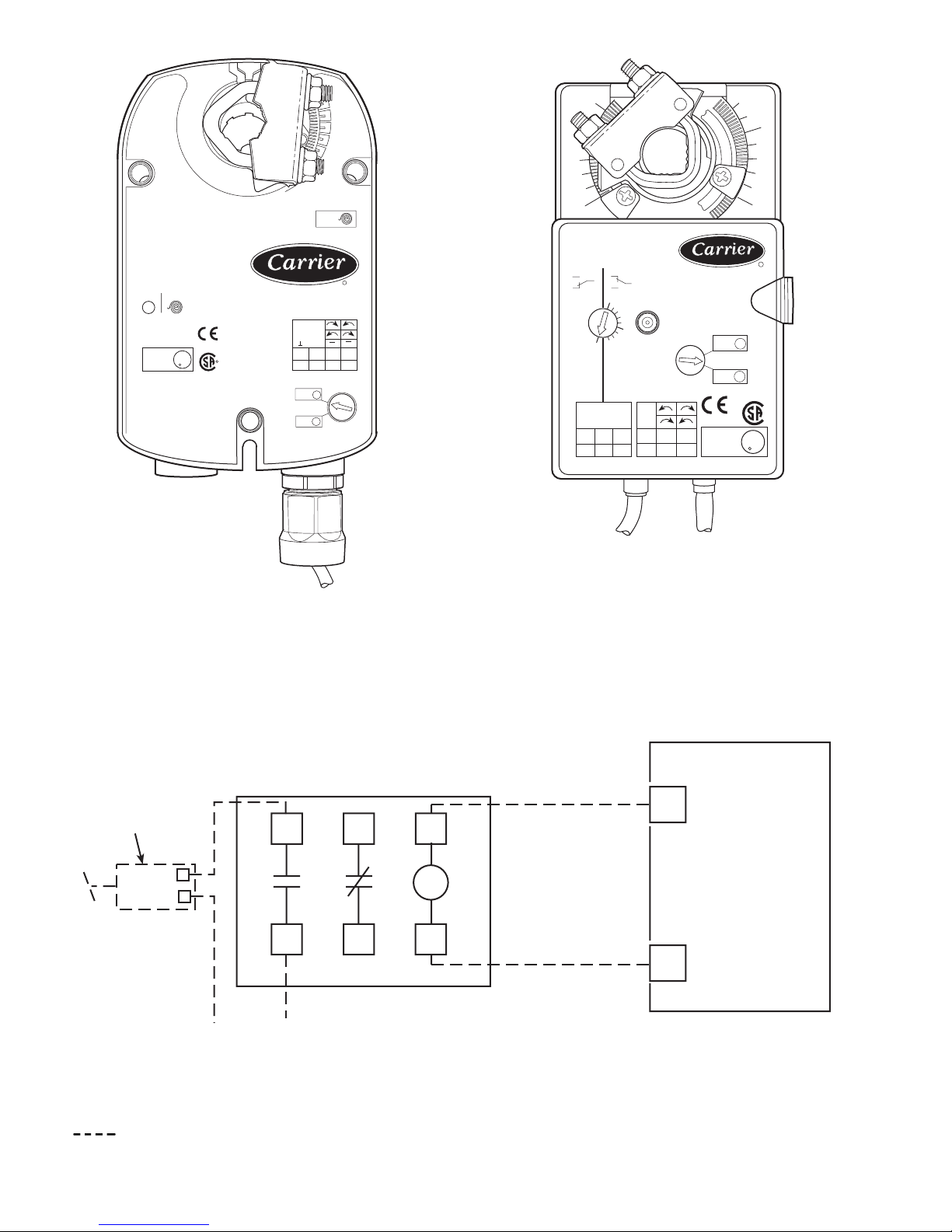
CW
HF23BJ040
Made in Switzerland
by Belimo Automation
35 in-lb (4 Nm)
20s
150s
M
NEMA 2
Class 2 Supply
LISTED
94D5
U
TEMP.IND. &
L
REG. EQUIP.
LR 92800
24VAC/DC
50/60Hz
5VA
2.5W
COM
CCW
CW
~~~
2
1
red
blk
+
CCW
M
CW
M
R
3
grn
wht
W3
Direction
Control
4
W4
Fig. 28 — Modulating Outdoor-Air Damper
Actuator (Part No. HF23BJ040)
CCW
CW
M
M
LR 92800
U
1
R
L
0
HF23BJ039
Made in Switzerland
by Belimo Automation
S2
S2
S1
S1
S3S3
(CW)
1
.5
0
(CCW)
24VAC/DC
5 (2.5)A
S2
S3 1
S1
yel
blu
ora
24VAC/DC
50/60Hz
3VA 2W
CCW
CW
red
blk
COM
35 in-lb (4 Nm)
80...110s
3
2
wht
+
+
NEMA 2
LISTED
94D5
TEMP.IND. &
REG. EQUIP.
Class 2 Supply
Fig. 29 — Face and Bypass Damper
Actuator (Part No. HF23BJ039)
FIELD-SUPPLIED
DAMPER HRV OR
ERV
2
4
(HN61KK324 RELAY SHOWN)
SEPARATE ISOLATED
POWER SOURCE
(24, 120, OR 240 VAC.)
LEGEND
ERV — Energy Recovery Ventilator
HRV — Heat Recovery Ventilator
Field Wiring
Fig. 30 — Two-Position Minimum Outdoor-Air Damper Relay
5
1
63
40
(BLK)
(RED)
J1
2
T34
CONTROL BOARD
TERMINAL
Page 41
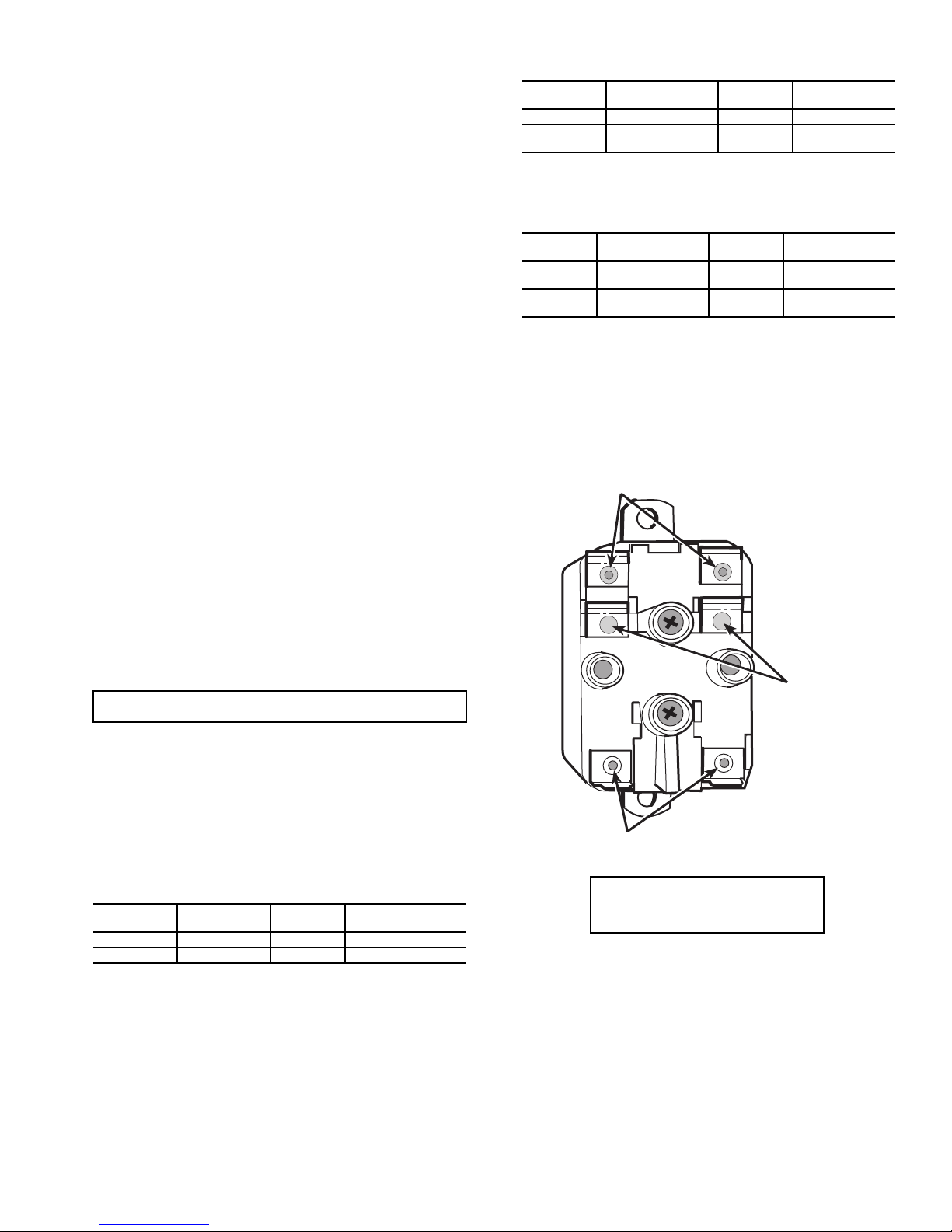
Direct Expansion (DX) Cooling — The Unit Venti-
lator Comfort Control module is designed to provide up to
2 stages of capacity control for direct expansion (DX) cooling
applications. The control can be interfaced with condensing
units, unloader solenoid valve, hot gas bypass valves, and liquid line solenoid valves. In these applications, the stages of DX
capacity are controlled to maintain the space temperature at the
cooling set point. Typically, compressor stages and liquid line
solenoid valves operate normally open, while unloaders and
hot gas bypass valves operate normally closed (see Fig. 31).
The Unit Ventilator Comfort Control module provides a
SPDT relay contact for the first stage of DX cooling. These
contacts are designed to switch up to 1 ampere of power (24 to
277 vac at 60 Hz).
Each DX output is configured to provide a minimum off
time of 5 minutes after being deenergized. This Time Guard
control feature allows the refrigerant pressures to equalize after
a compressor shutdown, thereby protecting compressors from
damage caused by starting with excessive loads. The Time
Guard control can be disabled if the stage is used to control a
solenoid valve or unloader.
OUTDOOR-AIR TEMPERATURE (OAT) LOCKOUT —
An outdoor-air temperature lockout is provided to disable all
DX cooling. The control compares the outdoor-air temperature
to the user-adjustable DX outdoor air lockout set point.
Whenever the OAT drops below the set point, all stages of DX
cooling are disabled.
The outdoor-air lockout feature is used to ensure the
condensing unit does not operate below its designed minimum
outdoor temperature.
DX System Design — Recommendations for basic DX
system design and piping should always be followed and are
available in the Carrier System Design manual.
The Unit Ventilator Comfort Control module maintains the
space temperature at the cooling set point by operating the DX
stages as the space load requires. Configuration requirements
for systems using DX components vary according to the
system design.
IMPORTANT: Never oversize the condensing unit.
For units equipped with CCN controls, condensing units
should be sized for medium speed airflow unless a hot gas
bypass valve or two-stage condenser is supplied.
Several staging control examples for typical DX applications are shown in Examples 1-3. Use a service configuration
tool to configure the number of stages and the logic type and
Time Guard control features. See Set-Up, Configuration and
Operation section on page 46 for further configuration details.
Example 1 — Single-Stage Single Condensing Unit
STAGE
NUMBER
1 Compressor Normal Enabled
2 Hot Gas Inverted Disabled
STAGE
TYPE
LOGIC
TYPE
TIME GUARD
FUNCTION
Example 2 — Two-Stage Single Condensing Unit
STAGE
NUMBER
1 Compressor Normal Enabled
2
*Optional, based on the system design or hot gas bypass.
STAGE
TYPE
Electric
Unloader no. 1*
LOGIC
TYPE
Inverted Disabled
TIME GUARD
FUNCTION
Example 3 — Condensing Unit with
Two-Speed Compressor
STAGE
NUMBER
1
2
STAGE
TYPE
Compressor
or Low Speed
Compressor
or High Speed
LOGIC
TYPE
Normal Enabled
Normal Enabled
TIME GUARD
FUNCTION
The preceding examples are typical; however, staging for
each system is unique. Staging is for capacity control only and
does not eliminate any components required for safety or by
recommended system design. Follow equipment application
and installation instructions for sizing, location of electrical
connections, and required components such as liquid-line
solenoid valves used for refrigerant isolation, and thermostatic
expansion valves.
NORMALLY OPEN CONTACT TERMINALS
24
56
NORMALLY
CLOSED
CONTACT
TERMINALS
3
1
COIL TERMINALS
RELAY CONTACT RATINGS
48 va at 24 vac 0.25 power factor
125 va at 115 vac 0.25 power factor
230 va at 230 vac 0.25 power factor
Fig. 31 — DX Control Relay (Part No. HN61KK324)
41
Page 42
Electric Heat — Two control relays are factory-supplied,
factory-installed and factory-wired to provide staging control
for electric heater applications. They are used to operate the
electric heater elements in two stages. The relays are installed
inside the electric heat control compartment. The heater circuit
connections depend upon the actual number of heater elements
provided. The Unit Ventilator Comfort Control module provides two stage electric heat control capability unless only one
element is provided.
The control operates the heater stages as required, but prevents the discharge air temperature from exceeding 140 F at
any time.
The first stage is wired so that it operates between 33 to
50 percent of the total heater capacity. Refer to Table 16 for
heater element circuit connections.
Remote Start — The remote start input is used to switch
the control operating mode from the unoccupied to the occupied state by means of a contact closure from an external control system or an electro-mechanical time clock device. The
control device must provide an isolated single-pole contact.
Whenever the contact is closed and 24 vac is present on T20,
the control will operate in the Occupied mode.
Using 18 or 20 AWG wire, connect the remote start terminal (T20) to one side of the remote contact. Connect the other
side of the contact to TB.
If a solid-state contact is provided by the control device,
then a field-supplied and field-installed load resistor may be
necessary to ensure reliable operation of the input. To ensure
proper operation, use a digital volt meter (DVM) and measure
the AC voltage between T20 and T25 with the external contact
in the OFF or open position.
The input will operate properly if the AC voltage is less than
1 vac, otherwise a load resistor must be connected across terminals T20 (remote start input) and T25 (ground). Typically, a
single 1000 ohm, 2 watt resistor will reduce the voltage sufficiently for most solid-state contacts. If not, add additional resistors, one at a time, until the voltage measured is below 1 vac.
Because the resistors heat when operating, the devices should
be permanently mounted to a field-supplied terminal strip and
20 AWG wire rated for at least 90 C should be used to connect
the resistor(s) to control terminals T20 and T25.
Fire/Smoke Status Input — The Fire/Smoke Status
Input is used to identify that a fan has stopped its normal operation due to an alarm condition at a local fire or smoke detector.
This input must be used in conjunction with a normally closed
contact which is wired into the fan motor control circuit.
A double-pole double-throw (DPDT) relay, part number
HN61KK324, is recommended. One set of the relay contacts is
wired into the fan motor circuit and the other set is wired to the
control input. The control box provides 24 vac power for the
relay. The relay is controlled by a separate isolated contact set
from the smoke or fire detector.
All wiring from the detector should be appropriately rated
for the application and must comply with NEC, NFPA (National Fire Protection Association) and any local codes.
SMOKE/FIRE DETECTOR WIRING (Normally Open
Contact Set) — Perform the following procedure to wire the
smoke/fire detector:
1. Use15AWGwireratedfor600vacforallwiring.
1
/4-in. insulated female quick-connect type lugs
Eight
are required.
2. Connect a wire from TB to one of the detector contact
terminals.
3. Connect the other detector contact terminal to the relay
coil terminal no. 1.
4. Connect the other coil terminal, no. 3, to ground in the
control box.
5. Connect the normally closed contact set (relay terminals no. 5 and no. 6) to the fan motor wiring as shown
on the label diagram.
6. Connect one of the normally open relay contacts, terminal no. 2, to TB (24 vac).
7. Connect the other side of the contact, terminal no. 4, to
T21 on the control module.
SMOKE/FIRE DETECTOR WIRING (Normally Closed
Contact Set) — Perform the following procedure to wire the
smoke/fire detector:
1. Use15AWGwireratedfor600vacforallwiring.
1
/4-in. insulated female quick-connect type lugs
Eight
are required.
2. Connect a wire from TB to one of the detector contact
terminals.
3. Connect the other detector contact terminal to the relay
coil terminal no. 1.
4. Connect the other coil terminal, no. 3, to ground in the
control box.
5. Connect the normally open contact set (relay terminals
no. 2 and no. 4) to the fan motor wiring as shown on
the label diagram.
6. Connect one of the normally closed relay contacts, terminal no. 5, to TB (24 vac).
7. Connect the other side of the contact, terminal no. 6, to
T21 on the control board.
TOTAL NO.
OF HEATER
CIRCUITS
3 133267
4 250250
5 240360
6 233467
NO. OF CIRCUITS
CONTROLLED
BY STAGE 1
Table 16 — Heater Element Wiring
STAGE 1
CAPACITY (%)
NO. OF CIRCUITS
42
CONTROLLED
BY STAGE 2
STAGE 2
CAPACITY(%)
Page 43
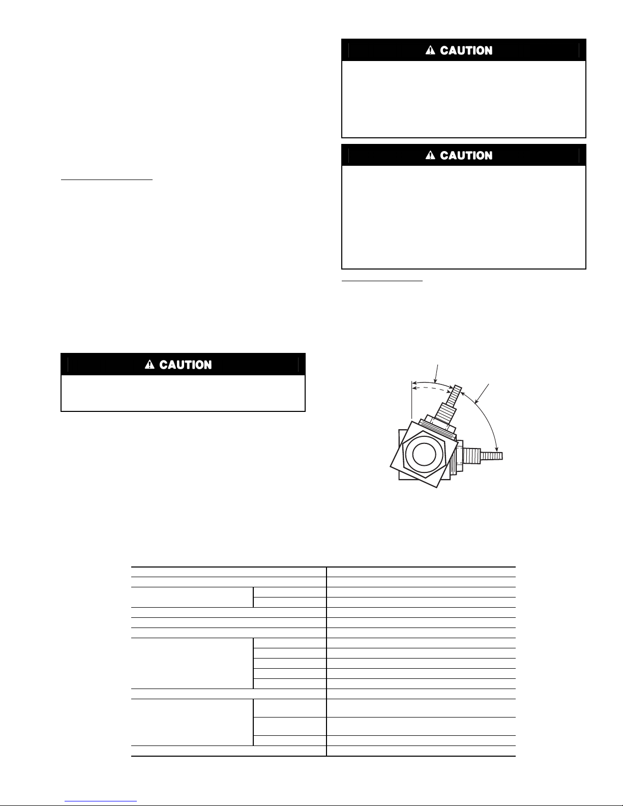
Valves
WATER VALVES — Water valve assemblies are shipped
with the unit for field installation. All factory-supplied valves
are fully modulating and capable of being positioned at any
point within the travel range of the valve. Each valve is
shipped complete with an actuator and any required linkage.
The equal percentage characteristics of the modulating
valves provide close temperature control on heating, cooling or
reheat unit ventilator coils.
In case of power failure, a return spring sends the valve to
its normal position. The normal position is defined for each
control sequence.
Water Valve Actuators
mounted on factory-supplied valve assemblies. The valve and
actuator assemblies are modulating spring return for all water
and steam applications. Valves are factory supplied.
All valves use actuators with reversible electric motors. The
control provides proportional control to the electric motor
which receives a tri-state signal from the control.
All valves have a spring return feature that allows them to
return to a normal positions (normally closed) upon loss of
power.
All valve assemblies have electrically powered actuators.
Each actuator is factory-wired and operates its valve through a
linear stroke.
Each water valve actuator features a magnetic clutch to extend the life of the motor and gear train. A manual override lever and position indicator facilitates field setup.
To prevent electric shock and equipment damage, disconnect the power to the control before performing any work
on valve assemblies.
— Water valve actuators are factory-
.
The manual positioning lever on all water valves should
only be used when controller power is OFF. DO NOT
attempt to move this lever when controller power is
applied. If the position lever does not move freely for manual positioning when the power is off, remove the valve
cover and push the solenoid plunger down using a small
screwdriver inserted in the slot below the solenoid.
DO NOT install valve assembly where excessive moisture,
corrosive fumes, and/or vibration are present.
INSTALL all 2-way valve assemblies so that they close
against system flow. Proper flow direction is from inlet
‘B Port’ to outlet ‘A Port’.
ALWAYS install 3-way mixing valve with 2 inlet flows
and one outlet. Proper flow direction is: inlet ‘B Port’ to
coil. Inlet ‘A Port’ to supply. “Common Port’ to return. See
Fig. 33.
Water Val ve Wirin g — Valve wiring is determined by the
actual valve selected and the control sequence.
All valves are factory-wired to the control module and
tested.
Water valve specifications and dimensions are found in
Table 17 and Fig. 34.
DO NOT MOUNT
VALVE HERE
VERTICAL
45° MINIMUM/
90° MAXIMUM
FROM VERTICAL
On chilled water or hot water applications, the valve actuators can be mounted in any position above the center line of the
valve body. For steam applications, mount the actuator above
the centerline of the valve body and at least 45 degrees from
vertical. This position prevents exposing the actuator to extreme heat. Refer to Fig. 32.
Table 17 — Water Valve Specifications
FEATURE SPECIFICATION
Application Hot or Chilled Water, up to 50% Glycol
Fluid Temperature
Flow Type Equal % Service Port Linear Bypass (3-way only)
Static Pressure Limits 300 psi (20.7 bar)
Current Requirement (24 V Supply) 12 VA (in rush), 100 mA Continuous
Material
Maximum Ambient Temperature and Humidity 125 F (52 C) 95% Non-Condensing
Actuator
Weight 3.0 lb (1360 g)
Minimum 32 F (0° C)
Maximum 200 F (93 C)
Body Forged Brass
Stem Chrome-Plated Brass
Seat Stainless Steel
Plug High Temperature Thermoplastic
Actuator Stainless Steel Base, Aluminum Cover
Vol tag e
Power
Connections Screw Terminals
Fig. 32 — Valve Mounting Angle for
Steam Heating Applications
24vac—15%, +10%
50/60 Hz
12 VA inrush at 24 vac
2.5 VA holding
43
Page 44

B
A
WATER
COIL
WATER
COIL
COM
RETURN
SUPPLY
3- WAY VALV E
AB
RETURN
SUPPLY
2- WAY VALV E
Fig. 33 — Typical Piping for Spring Return
2-Way and 3-Way Mixing Valves
The valve type is identified by the first digit of the two-digit
control code number. In Table 18, the water valve type is
shown for each unit depending on coil capacity.
NOTE: Dimensions are in inches (mm).
Fig. 34 — Water Valve Dimensions
(Modulating Type)
For pressure drops other than those tested, see Table 19. See
Tables 20 and 21 for close-off pressure.
Table 18 — Factory-Supplied Water Valves
CONTROL SEQUENCE APPLICATION VALVE APPLICATION NORMAL POSITION
DX — Direct Expansion
2A/3A Chilled/Hot Water (Modulating Valve) Control Chilled Water/
2B/3B Chilled Water Cooling, Hot Water
2D/3D Chilled Water Cooling, Electric Heat Chilled Water Open
2F/3F Hot Water or Steam Heating Only Hot Water/Steam Open
2G/3G Hot Water or Steam Heating, DX Cooling Hot Water/Steam Open
2J/3J Chilled Water Cooling Only Chilled Water Open
2K/3K Face and Bypass Chilled Water Cooling
2M/3M Face and Bypass Chilled Water Cooling
20/30 Chilled Water/Hot Water Using Face
21/31 Chilled Water Cooling, Hot Water or
22/32 Chilled Water Cooling, Electric Heat Chilled Water Open
23/33 Hot Water or Steam Heating, DX Cooling Hot Water/Steam Open
24/34 Hot Water or Steam Heating Only Hot Water/Steam Open
25/35 Chilled Water Cooling Only Chilled Water Open
LEGEND
or Steam Heating
with Valve Control Heating
with Valve Control Reheat
and Bypass Damper Control
Steam Heating
Hot Water
Chilled Water
Hot Water/Steam
Chilled Water
Reheat
Chilled Water
Reheat
Preheat
Chilled Water/
Hot Water
Chilled Water
Hot Water/Steam
Open
Closed
Open
Closed
Open
Closed
Closed
Open
Open
Closed
Open
44
Page 45
Table 19 — Valve and Coil Pressure Drops vs Flow
UNIT
SIZE
(NOMINAL
CFM)
500
750
1000
1250
1500
2000
LEGEND
Cv — Coefficient of Volume
*Hot water only.
NOTE: Desired Pressure Drop =
COIL
ROWS
1* 2.5 3.1 4
2* 2.5 3.3 4
32.53.34
42.53.34
52.53.34
1* 2.5 3.1 4
2* 2.5 3.5 4
32.53.34
42.53.34
52.53.34
1* 2.5 3.6 4
2* 2.5 3.5 4
34.046
44.046
54.046
1* 2.5 3.6 4
2* 2.5 3.5 4
34.06.78
44.06.78
54.06.78
1* 2.5 3.6 4
2* 2.5 3.8 4
3 4.0 10.8 10
4 4.0 10.8 10
5 4.0 10.8 10
1* 2.5 3.6 4
2* 2.5 3.8 4
3 4.0 10.8 10
4 4.0 10.8 10
5 4.0 10.8 10
SUPPLIED
VALV E
(Cv)
(
TYPICAL VALVE
AND COIL
PRESSURE DROP
psi gpm
desired gpm flow
flow from table
2
)
Table20—2-WayWaterValveSpecifications
and Ratings
APPLICATION
Steam
Hot/Chilled Water
Chilled Water
Only
LEGEND
Cv — Coefficient of Volume
COEFFICIENT
VOLUM E
FLOW
Cv
1.3 35 OPEN
2.2 35 OPEN
4.4 35 OPEN
2.5 50 OPEN
4.0 35 OPEN
2.5 50 CLOSED
4.0 35 CLOSED
CLOSE-OFF
PRESSURE
PSI
POSITION
Table21—3-WayWaterValve
Specifications and Ratings
APPPLICATION
Hot/Chilled
Water
Chilled Water
Only
LEGEND
Cv — Coefficient of Volume
COEFFICIENT
VOLUM E
FLOW
Cv
2.5 50 OPEN
4.0 35 OPEN
2.5 50 CLOSED
4.0 35 CLOSED
CLOSE-OFF
PRESSURE
PSI
NORMAL
NORMAL
POSITION
(COIL)
2-WAY STEAM VALVES — All steam valves utilize an
electrically driven hydraulic actuator which provides a full
modulating capability and a return feature. Each steam valve is
factory-equipped with a spring linkage extension to prevent
Table 22 — 2-Way Valve Specifications
Application Steam
Fluid Temperature Maximum 281 F (138 C)
Steam Pressure Limits
Flow Type Equal%
Material
Valve Connections
Maximum Ambient Temperature 140 F (60 C)
Actuator
Weight 6.0 lb (3057 g)
NOTE: Avoid condensation which can facilitate corrosion. With 40 F (4C) water, the maximum allowable ambient dew point temperature is 68 F (20 C). Piping insulation must not
stop drainage at actuator mounting nut. Do not use hydraulic actuators with fluid temperatures below 40 F (4C).
Maximum Inlet 35 psi (241 kPa)
Differential 20 psi (138 kPa)
Body Bronze
Stem Stainless Steel
Seat Bronze
Plug Brass
Packing Spring Loaded Teflon
Disc Composition
Vol tag e 24 Vac -15%, +10% 50/60 Hz
Power 22 VA at 24 vac
Connections Wire Leads
any actuator damage due to high steam temperatures. Steam
valve specifications and dimensions are found in Table 22 and
Fig. 35.
Female, Union Sweat
5
/8in. ID (1/2in. Nominal Copper) Tube
45
Page 46
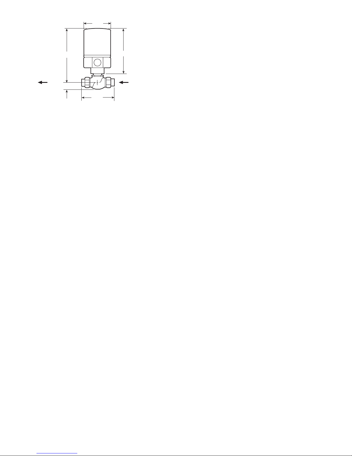
3-1/4
6-3/4
IN ‘A’
OUT
‘AB’
*9-25/32
1-5/16
4-1/4
FLOW
*Includes 21/32-in. (52 mm) for linkage extension.
NOTES:
1. Allow 3 in. clearance above actuator for removal. Mount actuators above the valve body at 45-degrees from vertical. Refer to
Fig. 32.
2. Dimensions are in inches.
Fig. 35 — Valve Dimensions
SET-UP, CONFIGURATION, AND
OPERATION
The Unit Ventilator Comfort Control module (P/N 110500)
is designed to be installed using the CCN Network Service
Tool, or a CCN Building Management system such as Building
Supervisor, ComfortVIEW™ or ComfortWORKS® software.
The control provides several comprehensive screens for easy
set-up and configuration of the control. See Tables 23-29. Two
additional screens display the operation of the equipment.
Each unit is factory-configured for the control sequence ordered. Only set points, schedules, alarm limits, and user options need to be adjusted. Tables 23-29 depict the screens that
provide a list of the information contained within each function, the expected range of values for each parameter, and the
allowable force limits or configuration range. For specific information about Network Service Tool, Building Supervisor,
ComfortVIEW, or ComfortWORKS software refer to the operating instructions for each specific piece of software.
The Service Configuration screens are used to specify the
equipment model and control sequence being used, such as the
type of heating or cooling used (chilled water, DX cooling,
steam, or hot water) and the damper control type (ASHRAE
Cycle I, II or III). These values are factory-configured for the
control sequence as ordered. A separate configuration screen is
used to modify the factory pre-configured alarm set points, if
required, in order to meet a specific customer requirement.
The service configuration screens are located under the
Diagnostic/Service Configuration function. See Table 24.
Alarm configurations are shown in Table 25.
The Modify controller screen allows the installer to select
from a list of standard control options which can be used for
specific applications. Standard control options include Space
Temperature Set Point adjustment with an adjustable maximum limit, the ability to provide dehumidification with or
without reheat, override duration, unoccupied free cooling, or
warm up temperature check, and other control features.
The control configuration screens are located under the
CCN Configuration function. See Table 27.
The Set Point screen is used to configure the desired control
set points for the specific application. These set points include
the occupied heating and cooling set points, the unoccupied
heating and cooling set points, the ventilation airflow set point,
the IAQ set point (optional) and the ASHRAE Cycle III Damper set point (for Cycle III control). The Set Point screen is located under the Modify/Set Points function. See Table 28.
The Points/Display screen is used to monitor equipment
operation and provides a simple overview including: the operating mode, heating and cooling capacity, ventilation airflow
value, equipment and sensor alarms, and a list of actual sensor
and output values. The Status Display screen is located under
the Points/Display function. See Table 26.
The Maintenance screen provides an indication of the
control algorithm operation and a view of each individual control loop as it is currently functioning. The Maintenance
screens are located under the Diagnostic/Maintenance function. See Table 29. The Linkage Maintenance screens are located under the Diagnostic/Maintenance function. See Table 29.
The Maintenance screen provides an indication of the information the Unit Ventilator Comfort Control module has received
from the linkage thermostat (if supplied).
Act — Actual
AQ — Air Quality
ASCII — American Standard Code
ASHRAE — American Society of
CCN — Carrier Comfort Network®
Cfg — Configured
Cntrl — Control
CV — Constant Volume
DI — Discrete Input
DX — Direct Expansion
Ele — Element
Hi Lim — High Limit
for Information
Interchange
Heating, Refrigeration
and Air Conditioning
Engineers
LEGEND (For Tables 23-29)
Hys — Hystersis
Kd — Derivative Constant
Ki — Integral Constant
Kp — Proportional Constant
Lo Lim — Low Limit
MAD — Mixed-Air Damper
MAT — Mixed Air Temperature
Med — Medium
min — minute
Norm — Normal
Nr — Number
OAT — Outdoor-Air Temperature
Oc/Occ — Occupied
PID — Proportional/Integral/
Sensor
Sensor
Derivative
46
Pos — Po si ti on
RH — Relative Humidity
Schd — Schedule
SP/Setpt — Setpoint
Stg — Stage
Sup Blk # — Supervisory Block
Sup Bus — Supervisory Bus
Sup Ele — Supervisory Element
Tem p/T mp — Temperature
Tim Gard — Time Guard
Tmd Ovr — Timed Override
Tmd Ovr Hrs — Timed Override Hours
Unoc — Unoccupied
Number
Number
Number
Page 47
Table 23 — CCN Device Configuration
DEVICE NAME DESCRIPTION LOCATION
40UV/UH
NOTE: The device name, description, and location fields can be modified by the
Building Supervisor or ComfortWORKS® software.
Comfort
System Unit
Ventilator
SOFTWARE
PART NUMBER
CESR-131191-02
Table 24 — Service Configuration
DESCRIPTION POINT NAME STATUS / UNITS RANGE DEFAULT
2 Pipe Changeover UNITTYPE Disable/Enable 0 - 1* Disable
ASHRAE Cycle Fan Control CYCLE x 1 - 3† 2
# Fan Speeds (1-3) FAN_TYPE x 1 - 3† 3
Unit Size UNITSIZE xxxx CFM 100 - 5000 1000
% Air Flow Med AFMED * % 30 - 100 80
% Air Flow Low AFLOW* % 20 - 100 70
Fan PID
Kp KP xx.x 0.0 - 40.0 10.0
Ki KI x.x 0.0 - 10.0 3.0
Kd KD xx.x 0.0 - 20.0 0.0
Starting Value STARTVAL xx.x % 0.0 - 100.0 0.0
Cooling Type CV Cooling COOL_TYPx 0-3† 0
Staged Cooling Nr of Stages STAGES x 1 - 2 1
Staged Heating Nr of Stages STAGES x 1 - 2 1
CV Mixed Air Damper
AQ Low Reference (PPM) AQLO xxxx 0.0 - 5000.0 0.0
AQ High Reference (PPM) AQHI xxxx 0.0 - 5000.0 2000.0
Filter Timer hrs * 100 FIL_TIMRxx 0-99 12
*0 = Disable or Normal
1 = Enable or Inverted
Kp KP xx.x 0.0 - 40.0 8.0
Ki KI x.x 0.0 - 10.0 0.3
Kd KD xx.x 0.0 - 20.0 0.0
Starting Value STARTVAL xx.x °F 40.0 - 90.0 65.0
Stg 1 Tim Gard TG1 Disable/Enable 0 - 1* Enable
Stg 2 Tim Gard TG2 Disable/Enable 0 - 1* Enable
Stage 1 Logic Type CLT1 Norm/Invert 0 - 1 Normal
Stage 2 Logic Type CLT2 Norm/Invert 0 - 1* Normal
Heating Type HEAT_TYPx 0-3† 0
Heating
Kp KP xx.x 0.0 - 40.0 8.0
Ki KI x.x 0.0 - 10.0 0.3
Kd KD xx.x 0.0 - 20.0 0.0
Starting Value STARTVAL xx.x °F 40.0 - 90.0 80.0
Fan Off Value HCFOV xx.x °F 35.0 - 70.0 55.0
Stg 1 Tim Gard TG1 Disable/Enable 0 - 1* Enable
Stg 2 Tim Gard TG2 Disable/Enable 0 - 1* Enable
Stage 1 Logic Type HLT1 Norm/Invert 0 - 1* Normal
Damper Type MIXDx 0-21
Kp KP xx.x 0.0 - 40.0 8.0
Ki KI x.x 0.0 - 10.0 0.3
Kd KD xx.x 0.0 - 20.0 0.0
Starting Value STARTVAL xx.x °F 40.0 - 90.0 60.0
Air Quality
Kp KPxx.xx 0-1.00.1
Ki KI xx.xx 0 - 1.0 0.03
Max AQOutput AQMDP xxx.x % 0.0 - 100.0 85.0
AQ Low Voltage Volts xx.x Volts 0.0 - 10.0 2.0
AQ High Voltage AQINHI xx.x Volts 0.0 - 10.0 10.0
Space Temp Trim RATTRIM xx.x ^F –5.0 - 5.0 0.0
MAT Sensor Trim MAT T R I M xx.x ^F –5.0 - 5.0 0.0
OAT Sensor Trim OATT R IM xx.x ^F –5.0 - 5.0 0.0
†0 = None
1 =Modulating
2 = Two Position
3 = If applicable, Direct Expansion (DX) for Cooling Type. Electric
Heating for Heating Type.
47
Page 48
Table 25 — Alarm Service Configuration
DESCRIPTION POINT NAME STATUS / UNITS RANGE DEFAULT
Alarm Routing Control ALRMCNT xxxxxxxx 0 - 1* 11010000
Realarm Time REALARM xxx min 1-255† 255
Cntrl Temp Hys xx.x ^F
Supply Air Temperature SPTHYS 1.0 - 20.0 5.0
Lo Lim LOWLIM xxx.x °F –40.0 - 245.0 45.0
Hi Lim HIGHLIM xxx.x °F –40.0 - 245.0 150.0
Mixed Air Temperature
Lo Lim LOWLIM xxx.x °F –40.0 - 245.0 40.0
Hi Lim HIGHLIM xxx.x °F –40.0 - 245.0 120.0
Relative Humidity
Lo Lim LOWLIM xxx.x %RH 0.0 - 100.0 30.0
Hi Lim HIGHLIM xxx.x %RH 0.0 - 100.0 70.0
Outdoor Air CFM
Lo Lim LOWLIM xxxx.x CFM 0.0 - 5000.0 0.0
Hi Lim HIGHLIM xxxx.x CFM 5000 - 5000 800.0
Air Quality
Lo Lim LOWLIM xxxx.x 0.0 - 5000.0 0.0
Outdoor Air Temperature
*0 = Disable
1 = Enable.
†255 disables realarming.
Hi Lim HIGHLIM xxxx.x 0.0 - 5000.0 800.0
Lo Lim LOWLIM xxx.x °F –40.0 - 245.0 40.0
Hi Lim HIGHLIM xxx.x °F –40.0 - 245.0 140.0
NOTE: Alarm retry time (in the event an alarm is not acknowledged)
is fixed at 5 minutes.
Table 26 — Status Display
DESCRIPTION POINT NAME STATUS / UNITS
Desired Mode MODE xxxxxx ASCII*
Equipment Status ALARM Norm/Alarm
Controlling Temperature SPT xxx.x °F –40.0 - 245.0
Space Temperature RAT xxx.x °F –40.0 - 245.0
Supply Air Temperature SAT xxx.x °F –40.0 - 245.0
Mixed Air Temperature MAT xxx.x °F –40.0 - 245.0
Outdoor-Air Temperature OAT E MP xxx.x °F –40.0 - 245.0
Fan Re lay SF Off/On0-1**
Fan Status FANSTAT xxxxxx ASCII†
Remote Start REMOTE Off/On0-1**
Outdoor Air Enthalpy ENT High/Low 0 - 1**
Cooling Capacity CCAP xxx.x %
Heating Capacity HCAP xxx.x %
Outdoor Air cfm OACFM xxxx.x CFM 0.0 - 5000.0
MAD Capacity 0.0 - 100.0 MIXDCAP xxx.x % 0.0 - 100.0
Filter Status FLTSTAT Clean/Dirty 0 - 1**
Air Quality (PPM) AQ xxxx.x 0.0 - 5000.0
Relative Humidity RH xxx.x %RH 0.0 - 100.0
Fire Shutdown Norm/Alarm
Coil Freeze Detection CFD Norm/Alarm 0 - 1**
Changeover Switch Input CHANGOVR Heat/Cool 0 - 1**
Spare Discrete Input DI0 Off/On0-1**
Mixed Air Damper 1 MIXD1 Off/On0-1**
Mixed Air Damper 2 MIXD2 Off/On0-1**
Heating Enable Output HEATING Off/On0-1**
Cooling Enable Output COOLING Off/On0-1**
*The text used for Mode shall be one of the following:
Off, Occ Cool, Occ Heat, Fan Only, UnocCool, UnocHeat, Warm-Up, Free Cool.
†The text used for Fan Status shall be one of the following:
Off, Low, Medium, High.
**0 =Off, High, or Clean 1 =On, Low, or Dirty.
NOTE: The presence of override limits indicates that the point is forcible, all others are read
only.
FS Fire shutdown
Spare Analog Input AI0 xx.x Volts 0.0 - 10.0
Cooling 1 CCV1 Off/On0-1**
Cooling 2 CCV2 Off/On0-1**
Heating 1 HCV1 Off/On0-1**
Heating 2 HCV2 Off/On0-1**
OVERRIDE
LIMITS
48
Page 49
Table 27 — CCN Configuration
DESCRIPTION POINT STATUS / UNITS RANGE DEFAULT
Warm-Up Temp Check WARMENAB Disable/Enable 0 - 1* Enable
Unoccupied Fan Cycling FAN_CYCL Disable/Enable 0 - 1* Disable
Unoccupied Free Cooling NTEN Disable/Enable 0 - 1* Enable
Free Cooling Lock-out NTLO xx.x °F 35 - 80 50.0
DXOutdoor Air Lock-out DXLO xxx.x °F –40 - 65 60.0
Max Offset Adjustment LIMT xx.x ^F0-200.0
Air Quality Control AQEN Disable/Enable 0 - 1* Disable
High Humidity Limit HIHUM xxx.x %RH 0 - 100 100.0
Local RH Sensor RHSENS No/Yes 0 - 1* No
Reheat REHEAT Disable/Enable 0 - 1* Disable
Occ Schd OCCSCHED xx 64 - 99† 64
Tmd Ovr Hrs TIMOVRID x hours 0 - 4 0
Linkage Thermostat
Cool Strt Bias (min/deg)KCOOLxx xx 0-60 10
Heat Strt Bias (min/deg)KHEAT xx min 0 - 60 10
*0 = Disable or No 1 = Enable or Yes
†Value below 65 (i.e., min value/default) disables global occupancy from CCN.
Table 28 — Set Point Configuration
DESCRIPTION POINT STATUS / UNITS RANGE DEFAULT
Setpoint
Oc Heat SP OHSP xx.x °F 40 - 90 70.0
Oc Cool SP OCSP xx.x °F 45 - 99 75.0
Unoc Heat SP UHSP xx.x °F 40 - 90 55.0
Unoc Cool SP UCSP xx.x °F 45 - 99 90.0
Cycle III Damper Setpt C3DSP xx.x °F 40 - 90 55.0
Economizer Lock-Out Temp ELOSP xx.x °F 40 - 90 63.0
Ventilation Setpoint OASP xxxx.x CFM 100 - 5000 200.0
AQ Setpoint (PPM) AQSP xxxx.x 0 - 5000 650.0
Table 29 — Maintenance
DESCRIPTION POINT STATUS / UNITS OVERRIDE LIMITS
Occupied OCCSTAT No/Yes
Linkage in Effect DAVCL No/Yes
Tmd Ovr in Effect TIMOV* No/Yes
Heat Master Reference HCMRxxx.x°F
Heat Submaster Reference HCSR xxx.x °F 35.0 to 140.0
Cool Master Reference CCMRxxx.x°F
Cool Submaster Reference CCSR xxx.x °F 40.0 to 150.0
MAD Master Reference MIXDMRxxx.x°F
MAD Submaster Reference MIXDSR xxx.x °F 48.0 to 120.0
Cfg MAD Min Position MIXDMDP xxx.x % 0.0 to 100.0
Act MAD Min Position DMPRMIN xxx.x %
Temperature Reset Value RESET xx.x ^F
Cooling in Effect COOLFLAG* No/Yes
Heating in Effect HEATFLAG* No/Yes
Reheat in Effect REHTFLAG* No/Yes
AQ Control in Effect AQFLAG No/Yes
AQ Calc Damper Pos MDPAQ*xxx.x%
Fan Status DI FAN DI Off/On
Fan Speed Relay 1 FANSPD1 Off/On0-1†
Fan Speed Relay 2 FANSPD2 Off/On0-1†
Linkage Thermostat Linkage Status LINKSTAT* x
†0 =Off 1 =On
NOTE: The presence of override limits indicates that the parameter is forcible;
all others are read only except those marked (*) which cannot be forced or read from CCN.
Sup Ele SUPE-ADR* xxx
Sup Bus SUPE-BUS* xxx
Sup Blk # BLOCKNUM*x
Avg Oc Heat SP OCLOSTPT* xx.x °F
Avg Oc Cool SP OCHISTPT* xx.x °F
Avg Unoc Heat SP UNLOSTPT* xx.x °F
Avg Unoc Cool SP UNHISTPT* xx.x °F
Avg Zone Tmp AZT* xx.x °F
Avg Oc Zone Tmp AOZT* xx.x °F
OcStat OCCSTAT* x
49
Page 50
START-UP
Start-up procedures vary depending on time of year (summer or winter) and building characteristics (new building/old
building, occupied/unoccupied, etc.).
Start-up in the cooling mode requires proper care to avoid
condensation problems. Condensation forms on surfaces that
are colder than the dew point of the surrounding air. If a unit is
started and is piped with low-temperature chilled water in a
hot, humid atmosphere, condensation will form on many parts
of the unit. In order to avoid excessive condensation, higher
temperature water should initially be used (approximately 65 to
70 F). Also, the building should be as completely closed as
possible. Close the unit’s outside-air dampers. Bathroom and
kitchen exhaust fans should be off.
As the building temperature drops, the chilled water temperature can be gradually reduced until it reaches 50 F. At this
point the outside-air damper can be opened to take in minimum
outside air. When the chilled water temperature is reduced to its
design point, the exhaust fans can be turned on.
SERVICE
Lock out and tag all power supplies to equipment and controls prior to servicing unit. Follow all safety codes. Failure
to do so could result in personal injury.
Preventing Excessive Condensation on Unit —
Excessive condensation can be caused by running chilled water
through a unit with the unit fan off. If fan cycling is used, a water
flow control valve should be installed to shut off the water when
the fan stops.
Other methods of control which avoid condensation problems are as follows:
1. If condensation is forming on the unit, verify the chilled
water valve is closing off tightly. Dirt or debris may prevent the valve from closing completely.
2. Continuous fan operation with motorized chilled water
valve controlled by a thermostat.
3. Continuous fan operation with thermostat control to
switchfanfromhightolowspeed(insteadofoff).
Check Drain — Check drain pan, drain line, and trap at
start of each cooling season. A standard type pipe cleaner for
3
/4-in. ID pipe can be used to be sure pipe is clear of obstruction
so that condensate is carried away. Check the drain line at filter
cleaning time during the cooling season. Be sure that debris has
not fallen into unit through supply air grille.
Fan Motor Bearings — Standard motors are perma-
nent split capacitor, which are equipped with permanently
sealed and lubricated bearings. No lubrication is required
unless special motors have been supplied or unusual operating
conditions exist.
Fan Shaft Ball Bearing — These mid and inboard
bearings are permanently sealed and lubricated. No additional
maintenance is required. The end bearings must be lubricated at
the start of each cooling and heating season. Add 5 to 10 drops
of SAE 20 or 30 non-detergent based oil to the bearing.
Clean Fan Wheel — For access to fan assembly, remove
discharge grille (if supplied). If unit is connected to ductwork,
remove front (40UV) or bottom (40UH) panel, separate fan
shaft from motor at bushing, remove motor, and slide fan
assembly from track. Use a stiff brush or vacuum to remove
dirt and debris from scroll. Wipe all fan surfaces with a damp
cloth. Reassemble as necessary.
Clean or Replace Air Filters — At the start of each
cooling season and after each month of operation (more or less
depending on operating conditions), replace throwaway filter
or clean permanent filter.
THROWAWAY FILTER — Replace filter with a good quality
filter of the correct size. Do not attempt to clean and reuse
disposable filters. See Table 1 for filter sizes.
PERMANENT FILTER (Fiber Type)
1. Tap on solid surface to dislodge heavy particles.
2. Wash in hot water. If needed, use mild solution of commercial solvent such as sal soda or trisodium phosphate.
3. Set filter on end so that water drains out through slots in
frame. Allow filter to dry thoroughly.
4. Recharge filter with recharging oil. Three ounces is sufficient for a medium size filter. Oil may be applied by
insect spray gun. For easier spraying, the oil can be
warmed.
If the filter is dipped in the recharging oil, remove it
immediately and allow to drain through slots in frame.
5. Replace filter in unit.
If another type of filter is used, follow the filter manufactur-
er’s instructions.
ECM Motor Removal and Reinstallation
(Fig. 36) —
Commutated Motor (ECM) to drive the indoor fan.
The ECM is a factory programmed motor that is standard
with factory-supplied controls (CCN) and units without
factory-supplied controls that are used in high-static applications or high-capacity coils.
The ECM is programmed with an algorithm that maintains
a constant torque as the static pressure on the system varies.
For example, as the filter pressure drop increases due to dirt,
the fan will increase speed (rpm) to maintain the cfm.
The ECM is identified by the two electrical receptacles
located on the housing. See Fig. 8A, 8B, and 36.
The first receptacle is a 5-row in-line connector that feeds
the motor line voltage. This may be either 115 volts or
230 volts. Units that are wired for 230 volts have a jumper between terminals 1 and 2 on this plug (see wiring diagram).
The second receptacle on the motor is a 16-pin connector
and is used for speed switching. This is a low voltage (24-volt)
connection. There is a jumper wire between terminals 1 and 3.
This is a 24-volt ground. Voltage is present at all times when
the motor is energized.
NOTE: A time delay exists between the time the motor speed
is switched and the motor’s reaction. This is designed into the
electronics and does not indicate motor problems.
When replacing the motor, note the following:
• Check the part number of the old motor against that of
the replacement. There is a tag indicating the eight-digit
part number and begins with UVE. This is the program
number used for this motor.
• The motor must be installed per the instructions below.
It is important to maintain the dimension between the
fan compartment bulkhead and the coupling.
IMPORTANT: If a replacement cooling shroud has been
supplied, it should be installed and the old one
discarded. The motor shroud directs cooling air across
the motor to provide proper cooling. Never run the
motor without the cooling shroud in place. Ensure
the shroud inlet ring does not touch the motor; a gap of
1
/16in. to1/8in. is acceptable.
Carrier unit ventilators utilize an Electronically
50
Page 51
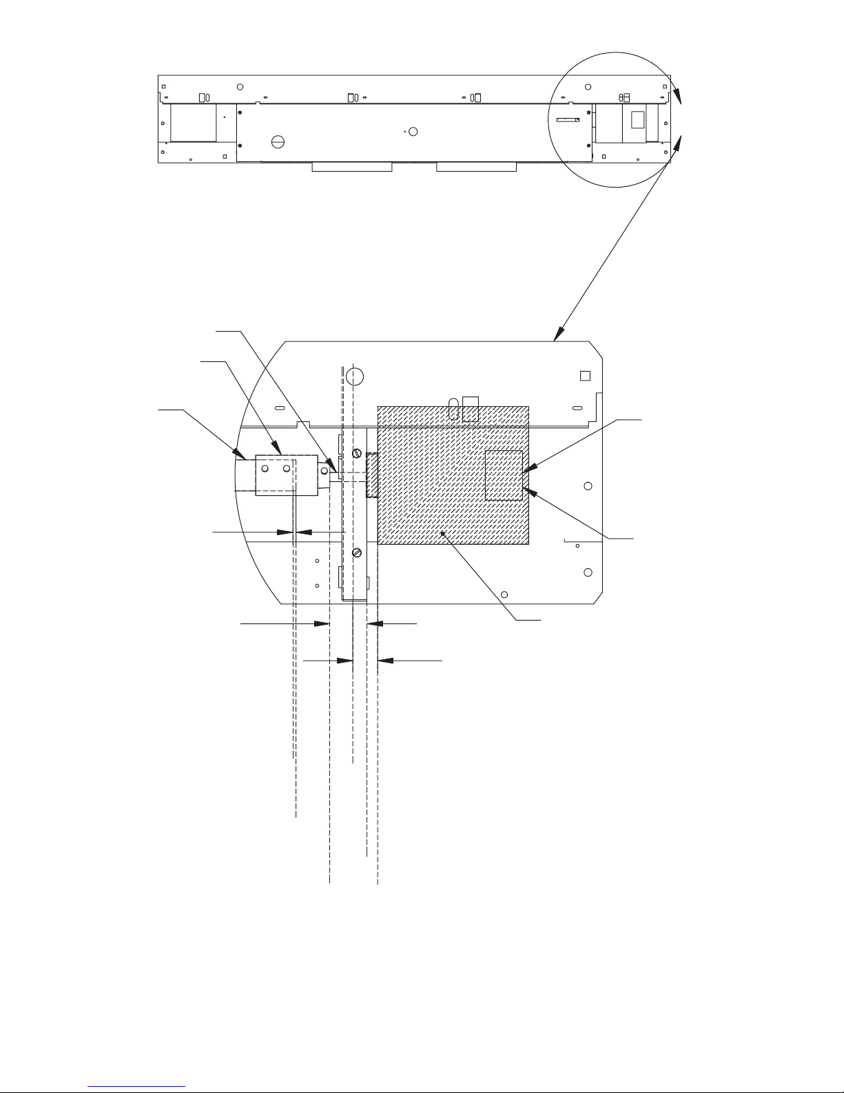
MOTOR SHAFT
COUPLING
FAN
SHAFT
+
.125 .032
–
0.500 0.063
INSTALL MOTOR
AND COOLING
SHROUD
ELECTRICAL
CONNECTIONS
FACING UNIT
FRONT.
CENTER SHROUD
OPENING OVER
MOTOR ELECTRICAL
CONNECTIONS.
+
–
+
1.000 0.063
–
SHAFTED END FACE
INSULATION FACE
MOTOR (ECM)
Fig. 36 — 40UV,UH Ventilator Blower Section Assembly — ECM Motor Detail
COUPLING INSIDE FACE
COUPLING FACE
MOTOR BEARING FACE
MOTOR FACE
51
NOTES:
1. All dimensions shown in inches.
2. Not all components shown for clarity.
3. Motor shroud not shown for clarity. Install prior
to operation.
4. Refer to Fig. 42 for cooling shroud installation.
Page 52
Ensure the unit is completely assembled when checking the
fan speed. Replace all panels, including the filters, before
checking the fan for operation. When the internal pressure
drops at a normal condition, the loading on the motor will
be such that the fan can come up to selected speed.
Failure to ensure unit is completely assembled may
result in reduced life of unit and/or personal injury.
Blower Assembly Section Removal and Reinstallation (Fig. 37)
Lock out and tag all power supplies to equipment and controls prior to servicing unit. Follow all safety codes. Failure
to do so could result in personal injury.
To remove and re-install the motors, proceed as follows;
refer to Fig. 36:
1. Remove the wire plugs from the motor.
2. Remove the 2 screws holding the motor shroud to the
bulkhead.
3. Slide the shroud off the motor to the right.
4. Loosen the 3 setscrews on the shaft coupling between the
motor shaft and the fan shaft.
5. Loosen the motor ‘belly band’ and slide motor out of the
‘belly band’ to the right. It is unnecessary to remove the
motor mounting bracket from the bulkhead. Loosen only
the ‘belly band’ securing the motor in the mount.
6. Reinstall the motor in the ‘belly band.’
7. Ensure the blower wheels are centered within the fan
housings (between the inlet rings) before securing the
motor shaft coupling.
The motor electronics will fail prematurely if no air is able
to circulate over the motor.
8. Ensure the motor housing is at least 1 in. from the
bulkhead so that air will be able to circulate over the
motor.
9. For vertical type units, position the motor so that the
motor wire plugs are front facing on a horizontal plane.
For horizontal type units with ceiling mounts, position the
motor so that the motor wire plugs are front facing on a
vertical plane.
10. Secure the 3 setscrews on the shaft coupling when the
motor is properly positioned and the blower wheels are
centered within their housing.
11. Re-secure the motor ‘belly band’ around the motor.
12. Reinstall the motor shroud. It is important that the motor
shroud be installed prior to operation of the motor. Ensure
the venturi is installed on the motor shroud.
13. Re-secure the two screws holding the motor shroud to the
bulkhead.
14. Reinstall the motor wire plugs.
Be careful with all components during installation, especially the bearing and plastic blower wheels. Any extreme
force applied to these components can cause unintended
damage and could void the unit warranty.
To remove blower assembly:
1. Turn off power to the unit.
IMPORTANT: Tag each right front panel (40UV) or
middle bottom panel (40UH) for each unit. Panels have
electrical information specific to each unit.
2. Remove all front (40UV) or bottom (40UH) panels. Remove end panels.
3. Remove top panel with
5
/16in. nut driver and set optional
vanes and screens to the side (40UV). Remove ductwork
if required and remove top (40UV) or front (40UH) discharge plenum.
1
4. Remove
/4in. head screws along length of unit that se-
cure coil baffle to blower section. See Item 5 in Fig. 37.
5. Remove four
1
/4in. head screws that connect the blower
section sides to the coil section sides. See Item 2 in
Fig. 37.
6. Remove the
1
/4in. head screw from the center of the
blower deck that attaches the blower deck to the pipe
chase. See Item 1 in Fig. 37.
7. Remove six
1
/4in. head screws attaching coil baffle to
coil section. See Item 4 in Fig. 37.
8. Remove the harness connector(s) from the motor.
9. Remove the
1
/4in. head screw from the green ground
wire that connects the motor to frame if unit has a PSC
motor. ECM motors are grounded through the harness.
10. Remove the two carriage bolts retaining the front brace to
the frame sides. See Item 6 in Fig. 37.
11. Remove the four nuts retaining the blower section to the
back (40UV) or top (40UH) frame. See Item 3 in Fig. 37.
5
12. Remove the two
/16in. nuts retaining the inboard bearing
bracket to the pipe chase (40UV,UH150 units only). See
Item6inFig.38.
13. Remove blower section from frame.
52
Page 53
To reinstall blower assembly to frame of unit:
1. Reinstall blower section into frame assembly.
2. Tighten the four
5
/16in. nuts retaining blower section to
frame. See Item 3 in Fig. 37.
5
3. Tighten the two
/16in. nuts retaining the inboard bearing
bracket to the pipe chase (40UV,UH150 units only). See
Item6inFig.38.
4. Reinstall two carriage bolts that attach the front brace to
the frame sides. See Item 6 in Fig. 37.
5. Rotate the fan shaft by hand to ensure that fans are
unrestricted and can rotate freely. Check for any fan
obstructions.
6. Re-attach green ground wire that connects the motor to
the frame with ¼ in. head screw if unit has a PSC motor.
ECM motors are grounded through the harness.
7. Connect harness connector(s) to motor.
8. Reinstall the coil baffle using six
1
/4in. head screws that
attach the coil baffle to the coil section. See Item 4 in
Fig. 37.
9. Reinstall the
1
/4in. head screw at center of blower deck
attaching blower deck to pipe chase. See Item 1 in
Fig. 37.
1
10. Reinstall the four
/4in. head screws holding the blower
section sides to the coil section sides. See Item 2 in
Fig. 37.
1
11. Reinstall
/4in. head screws along length of the unit,
securing coil baffle to the blower section. See Item 5 in
Fig. 37.
12. Reinstall optional vanes and screens and install top panel
(40UV). Reinstall top (40UV) or front (40UH) discharge
plenum and ductwork, if required.
13. Reinstall front (40UV) or bottom (40UH) panels. Reinstall end panels. Ensure that tag on each right front
panel (40UV) or middle bottom panel (40UH) matches unit tag.
14. Restore power to unit.
IMPORTANT: Disassembly order is not as important as
reassembly. The assembly order of the bearing bracket
installation is critical to having a well balanced and
sound blower deck.
Coil Assembly Removal and Reinstallation
(Fig. 39)
Lock out and tag all power supplies to equipment and controls prior to servicing unit. Follow all safety codes. Failure
to do so could result in personal injury.
Turn off all power supplies to equipment and controls. Failure to do so may cause personal injury or damage to the
unit.
To remove coil assembly:
1. Turn off power to the unit.
IMPORTANT: Tag each right front panel (40UV) or
middle bottom panel (40UH) for each unit. Panels have
electrical information specific to each unit.
2. Remove all front (40UV) or bottom (40UH) panels. Remove end panels.
3. Remove
1
/4in. head screws along length of unit that se-
cure coil baffle to blower section. See Item 2 in Fig. 39.
4. Remove four
1
/4in. head screws that connect the blower
section sides to the coil section sides. See Item 1 in
Fig. 39.
1
5. Remove
/4in. head screws attaching outside air (OA) actuator to damper shaft OR locking quadrant assembly to
damper shaft. Remove OA actuator or locking quadrant
assembly.
6. Tag low-limit thermostat wiring and terminals. Disconnect low-limit thermostat wiring (right end
compartment).
7. Drain water and/or recover refrigerant in accordance
with all applicable codes. Disconnect piping from coil
connections.
8. Tag optional electric heat element wire terminations for
later reconnection. Disconnect element wires from electric heat control box (remove coil baffle for access).
5
9. Remove the four
/16in. nuts retaining the coil section to
the frame.
10. Remove coil section from frame.
To reinstall coil assembly:
1. Replace coil section into frames assembly.
5
2. Tighten the four
/16in. nuts retaining coil section to
frame.
3. Reconnect electric heat wiring in electric heat control
box.
4. Reconnect wiring to low limit thermostat.
1
5. Replace the four
/4in. head screws holding the blower
deck to coil section (two on each side).
6. Replace coil baffle using
1
/4in. head screws. See Item 2
in Fig. 39.
7. Reinstall outside air actuator or locking quadrant handle
1
using
/4in. head screws.
8. Reconnect piping to coils. If water coil, purge air from
coils and perform hydrostatic test to check for leaks. If
DX coil, perform leak test using nitrogen, and evacuate
and charge per recommended HVAC procedures and all
applicable codes.
9. Replace coil section side insulation.
10. Replace front (40UV) or bottom (40UH) panels. Replace
end panels. Ensure that tag on each right front panel
(40UV) or middle bottom panel (40UH) matches unit
tag.
11. Restore power to unit.
53
Page 54
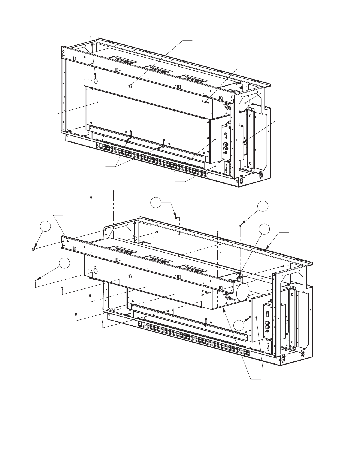
COIL BAFFLE
RETURN AIR
TEMPERATURE
SENSOR (OPTIONAL)
OPENING
FILTER DOOR RETAINER
CLIPS (SEE NOTE 3)
COIL SECTION
DAMPER SECTION
DISCHARGE AIR
TEMPERATURE
SENSOR (OPTIONAL)
OPENING
MOTOR & COUPLING
SETCREW ACCESS
MOTOR
MOTOR
ELECTRICAL
BOX
FRONT
BRACE
6
5
NOTES:
1. Unit shown in vertical orientation. Drawing applies
to horizontal and vertical units.
2. Not all components shown for clarity.
3. 40UV,UH125-200 units only.
Fig. 37 — 40UV,UH Ventilator Blower Section
1
2
3
PIPE
CHASE
4
COIL SECTION
BLOWER SECTION
54
Page 55
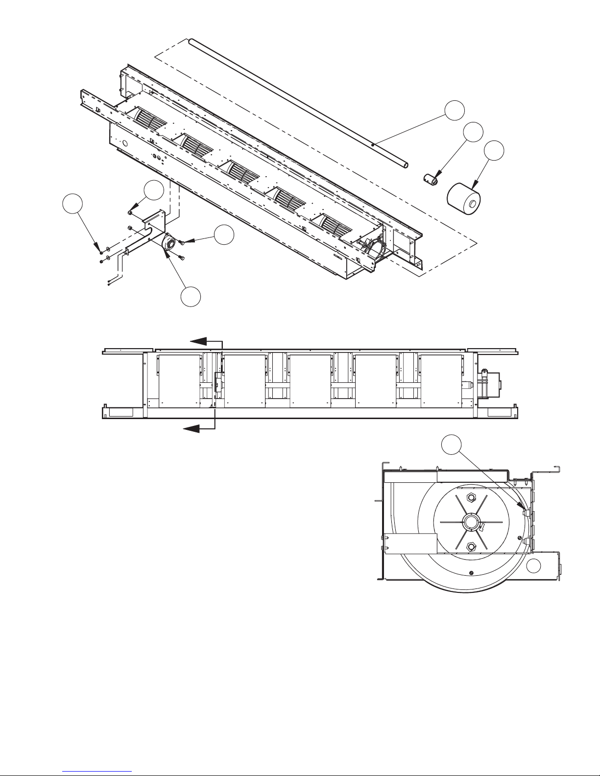
SEE NOTE 4
1
2
3
7
6
4
5
SEE DETAIL A
SEE DETAIL A
NOTES:
1. Not all components shown for clarity.
2. This drawing applies to 1500 cfm units only.
3. Remove shaft, motor, and coupling prior to
bearing removal.
4. Refer to Fig. 36 and 43 for motor-coupling and
coupling-shaft tolerances.
Fig. 38 — 40UV,UH Ventilator Inboard Bearing (40UV,UH150 Only)
BOTTOM VIEW
6
DETAIL A
55
Page 56
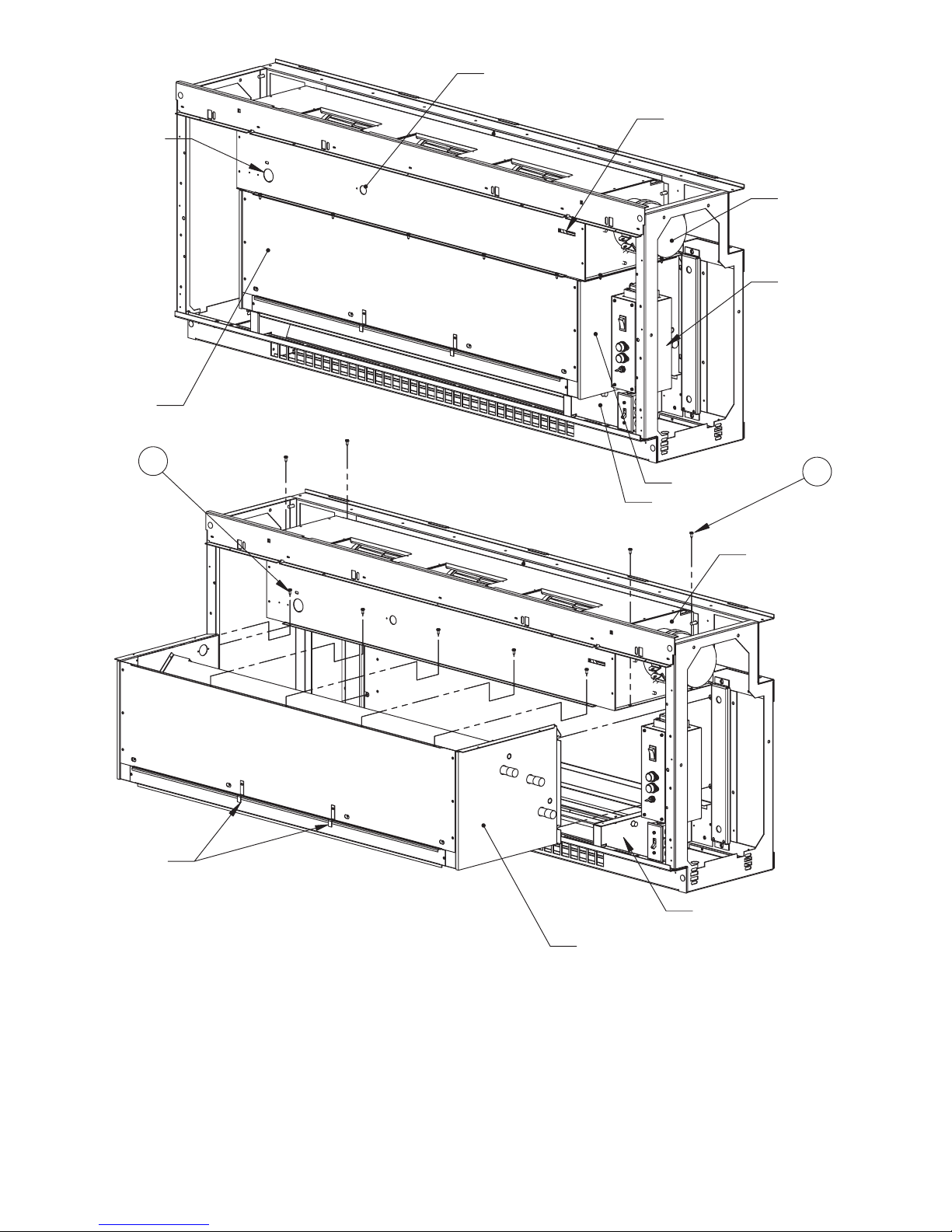
RETURN AIR
TEMPERATURE
SENSOR OPENING
FRONT
COIL
BAFFLE
DISCHARGE AIR
TEMPERATURE SENSOR
OPENING
MOTOR & COUPLING
SETSCREW ACCESS
MOTOR
MOTOR
ELECTRICAL
BOX
2
FILTER DOOR
RETAINER CLIPS
(SEE NOTE 3)
NOTES:
1. Unit shown in vertical orientation. Drawing
applies to horizontal and vertical units.
2. Not all components shown for clarity.
3. 40UV,UH125-150, 40UH200 units only.
COIL SECTION
DAMPER SECTION
COIL SECTION
DAMPER SECTION
1
BLOWER SECTION
Fig. 39 — 40UV,UH Ventilator Coil Section
56
Page 57
Ball Bearing Replacement (40UV,UH150;
40UH200 Units Only) —
units only, Fig. 41 for 40UV150 and 40UH150 units with PSC
motors, Fig. 42 for 40UV150 and 40UH150 units with ECM
motors.
Lock out and tag all power supplies to equipment and controls prior to servicing unit. Follow all safety codes. Failure
to do so could result in personal injury.
The assembly order of the bearing installation is critical. Be
careful with all components during removal and installation. Any excessive force applied to these components can
cause unintended damage and void unit warranty.
To replace ball bearing:
1. Turn off all power to unit.
IMPORTANT: Tag each right front panel (40UV) or
middle bottom panel (40UH) for each unit. Panels have
electrical information specific to each unit.
2. Remove front (40UV) or bottom (40UH) panels and right
(motor end) end panel.
3. Remove top panel and set optional vanes and screens to
the side (40UV). Remove ductwork if required and remove top (40UV) or front (40UH) discharge plenum. For
non-ducted 40UH horizontal units with front double deflection discharge grille, remove grille for access to wheel
setscrews. See Fig. 37.
4. Remove ¼ in. head screws along length of unit that secure coil baffle to blower section and remove front coil
baffle. See Item 5 in Fig. 37.
5. Loosen setscrews on all blower wheels (two per wheel).
See Fig. 38 and Fig. 40.
6. Loosen bearing setscrews.
7. Remove wiring harness connector(s) from motor.
8. If unit has ECM motor, remove motor shroud (sheet metal cover — Fig. 40, Item 6; Fig. 42, Item 4) by removing
5
/16in. hex nuts. Do not discard cooling shroud.
two
9. Loosen
Item 2; Fig. 42, Item 2), nut (Fig. 40, Item 3; Fig. 41,
Item 5; Fig. 42, Item 6), and bolt (Fig. 40, Item 4; Fig. 41,
Item 4; Fig. 42, Item 5), until motor housing (Fig. 40,
Item 5; Fig. 41, Item 3; Fig. 42, Item 3) moves freely.
10. Slide shaft-coupling-motor assembly (Fig. 38, Items 3, 2,
1; Fig. 40, Items 5, 2, 10) out of wheels and unit until
shaft clears inboard/center bearing assembly (30 in. max
clearance required from edge of frame end).
5
/16in. motor mount (Fig. 40, Item 7; Fig. 41,
Refer to Fig. 40 for 40UH200
11. Remove
1
/2in. bolts (Fig. 38, Item 4; Fig. 40, Item 9) and
hex nuts (Fig. 38, Item 7; Fig. 40, Item 1) securing bearing to bearing bracket. Remove bearing (Fig. 38, Item 5;
Fig. 40, Item 8).
12. Install new bearing (Fig. 38, Item 5; Fig. 40, Item 8).
Secure with
1
/2in. bolts (Fig. 38, Item 4; Fig. 40, Item 9)
and hex nuts (Fig. 38, Item 7; Fig. 40, Item 1).
13. Slide shaft-coupling-motor assembly (Fig. 38, Items 3, 2,
1; Fig. 40, Items 5, 2, 10) back into bearing and wheels.
Do not use excessive force. Damage to wheels may
occur.
14. Insert shaft-coupling-motor assembly into wheels until
motor clearance is as specified for motor type (PSC or
ECM). See Fig. 43 or Fig. 36.
15. Ensure that motor shaft is perpendicular to motor blower
endplate. Tighten
5
/16in. motor mount (Fig. 40, Item 7;
Fig. 41, Item 2; Fig. 42, Item 2), nut (Fig. 40, Item 3;
Fig. 41, Item 5; Fig. 42, Item 6), and bolt (Fig. 40, Item 4;
Fig. 41, Item 4; Fig. 42, Item 5), until motor (Fig. 40,
Item 5; Fig. 41, Item 3; Fig. 42, Item 3) is secure.
16. Install motor shroud (sheet metal cover — Fig. 40,
Item 6; Fig. 42, Item 4) using two
5
/16in. hex nuts if using
ECM motor. Align “window” with receptacles on motor.
Motor control module could overheat and fail if operated without cooling shroud.
17. Re-attach green ground wire that connects the motor to
the frame with
1
/4in. head screw if unit has a PSC motor.
ECM motors are grounded through the harness.
18. Re-attach wiring harness connector(s) to motor.
19. Center each wheel in its respective housing and tighten
wheel setscrews (two for each wheel).
20. Rotate the fan shaft by hand to ensure that fans are
unrestricted and can rotate freely. Check for any fan
obstructions.
21. Remove lockout and operate unit for approximately
60 seconds to let inboard/center bearing mount
self-adjust.
22. Lock out and tag all power supplies to equipment and
controls. Tighten the two bearing setscrews.
1
23. Reinstall the coil baffle using the six
/4in. head screws
that attach the coil baffle to the coil section. See Item 5 in
Fig. 37.
24. Reinstall
1
/4in. head screws along length of unit securing
coil baffle to the blower section. See Item 5 in Fig. 37.
25. Reinstall optional vanes and screens and install top panel
(40UV). Reinstall top (40UV) or front (40UH) discharge
plenum and ductwork if required or discharge grille.
26. Reinstall front (40UV) or bottom (40UH) panels. Reinstall end panels. Ensure that tag on each right front
panel (40UV) or middle bottom panel (40UH) matches unit tag.
27. Restore power to unit.
57
Page 58
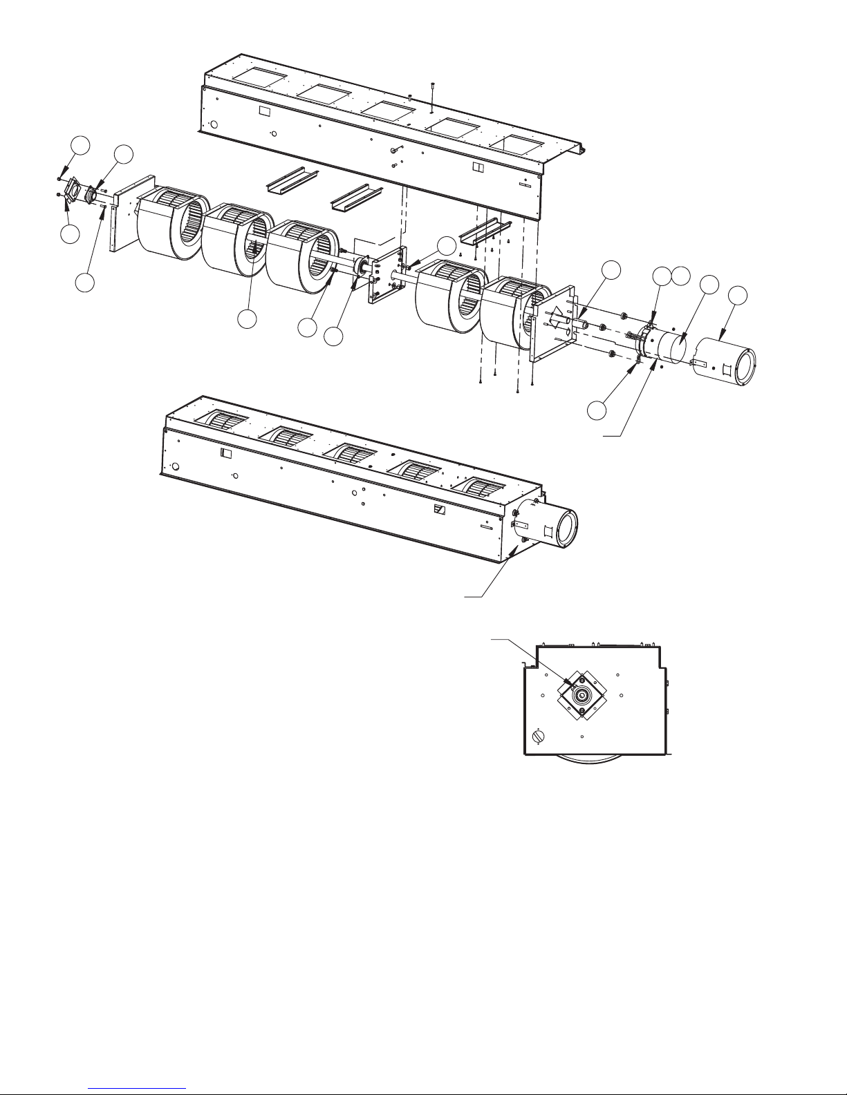
13
14
12
11
10
1
2
9
8
3
4
5
6
7
(SEE NOTE 5)
(SEE NOTE 5)
NOTES:
1. Not all components shown for clarity.
2. This drawing applies to 2000 cfm units only.
3. Remove shaft, motor and coupling prior to removing bearing.
Refer to Ball Bearing Replacement instructions.
4. Install sleeve bearing with oil cup facing up and towards the rear of
the assembly.
5. Refer to Fig. 36 for motor-coupling and shaft-coupling tolerances.
Fig. 40 — 40UH200 Ventilator Blower Drive Train Assembly
(SEE NOTE 4)
LEFT SIDE
VIEW
UNIT
BOTTOM
58
Page 59
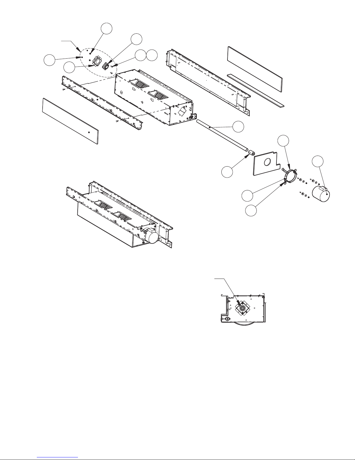
9
SEE NOTE 2
8
10
12
11
7
1
2
(SEE NOTE 3)
3
6
5
NOTES:
1. Not all components shown for clarity.
2. Items no. 7, 16 and associated hardware not required for
40UV,UH150. Refer to Fig. 38 for 40UV,UH150 in-board bearing
replacement.
3. Install motor with capacitor facing up.
4. Install sleeve bearing with oil cup facing up and towards the rear of
the assembly.
Fig. 41 — 40UV,UH Ventilator Blower Drive Train Assembly —
40UV050-150 and 40UH075-150 Units (PSC Motor)
(SEE NOTE 4)
4
UNIT FRONT (40UV)
UNIT BOTTOM (40UH)
59
Page 60
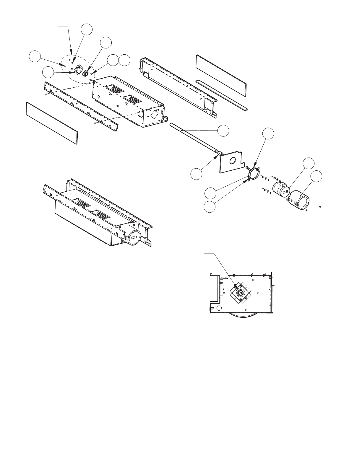
SEE NOTE 2
10
11
9
12
13
8
1
2
3
7
4
6
5
NOTES:
1. Not all components shown for clarity.
2. Items no. 7, 10 and associated hardware not required for
40UV,UH150. Refer to Fig. 38 for 40UV,UH150 in-board bearing
replacement.
3. Install motor with electrical connections facing front of assembly.
4. Install oil cup facing up and towards the rear of the assembly.
Fig. 42 — 40UV,UH Ventilator Blower Drive Train Assembly —
40UV050-150 and 40UH075-150 Units (ECM Motor)
(SEE NOTE 4)
LEFT SIDE
VIEW
UNIT FRONT (40UV)
UNIT BOTTOM (40UH)
60
Page 61
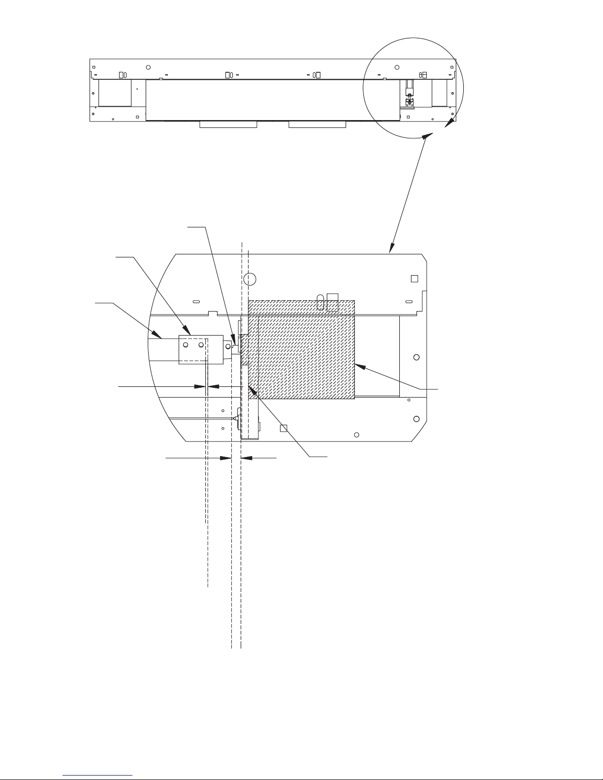
COUPLING
FAN
SHAFT
+
.125 .032
–
BLOWER SECTION
FRONT VIEW
MOTOR SHAFT
MOTOR (PSC)
+
0.500 0.063
–
SHAFTED END FACE
COUPLING INSIDE FACE
COUPLING FACE
MOTOR BEARING FACE
FACE OF MOTOR
FLUSH WITH FACE
OF INSULATION
NOTES:
1. All dimensions shown in inches.
2. Not all components shown for clarity.
Fig. 43 — 40UV,UH Ventilator Blower Section Assembly — PSC Motor Detail
61
Page 62
Blower Wheel Removal and Reinstallation
(Fig. 44) —
Fig. 41 for 40UV050-150 and 40UH075-125 units with PSC
motors, Fig. 42 for 40UV050-125 and 40UH075-150 units
with ECM motors.
Lock out and tag all power supplies to equipment and controls prior to servicing unit. Follow all safety codes. Failure
to do so could result in personal injury.
The assembly order of the bearing installation is critical. Be
careful with all components during removal and installation. Any excessive force applied to these components can
cause unintended damage and void unit warranty.
To remove blower wheel:
1. Turn off all power to the unit.
2. Remove blower section per service instructions in Blower
Assembly Removal and Reinstallation.
IMPORTANT: Tag each right front panel (40UV) or
middle bottom panel (40UH) for each unit. Panels have
electrical information specific to each unit.
3. Use
wheels (two per wheel).
4. Loosen inboard/center bearing setscrews (only on
40UV,UH150 and 200 size units).
5. If unit has ECM motor, remove motor shroud (sheet
metal cover — Fig. 40, Item 6; Fig. 42, Item 4) by removing two
6. Loosen
Item 2; Fig. 42, Item 2), nut (Fig. 40, Item 3; Fig. 41,
Item 5; Fig. 42, Item 6), and bolt (Fig. 40, Item 4; Fig. 41,
Item 4; Fig. 42, Item 5), until motor housing (Fig. 40,
Item 5; Fig. 41, Item 3; Fig. 42, Item 3) moves freely.
7. Slide shaft-coupling-motor assembly (Fig. 38, Items 3, 2,
1; Fig. 40, Items 5, 2, 10) out of wheels and unit until
shaft clears inboard/center bearing assembly (30 in. maximum clearance required from edge of frame end).
8. Remove four
blower housing(s) (Fig. 44, Item 7) to blower deck
(Fig. 44, Item 3) and remove blower and wheel assembly.
9. Remove five
blower inlet ring (Fig. 44, Item 4) to blower housing and
remove inlet ring.
10. Remove blower wheel(s) (Fig. 44, Item 8).
To reinstall blower wheel:
1. Install new blower wheel(s) (Fig. 44, Item 8). Ensure that
the fan blades are installed in the correct orientation (cup
of blade towards discharge).
2. Install inlet ring (Fig. 44, Item 4) and install five ¼ in.
head screws (Fig. 44, Item 5) securing blower inlet ring to
blower housing (Fig. 44, Item 7).
3. Install four
blower housing(s) (Fig. 44, Item 7) to blower deck
(Fig. 44, Item 3).
Refer to Fig. 40 for 40UH200 units only,
5
/32in. hex tool to loosen setscrews on all blower
5
/16in. hex nuts. Do not discard cooling shroud.
5
/16in. motor mount (Fig. 40, Item 7; Fig. 41,
1
/4in. head screw (Fig. 44, Item 6) securing
1
/4in. head screws (Fig. 44, Item 5) securing
1
/4in. head screws (Fig. 44, Item 6) securing
4. Slide shaft-coupling-motor assembly (Fig. 38, Items 3, 2,
1; Fig. 40, Items 5, 2, 10) back into bearing and wheels.
Do not use excessive force. Damage to wheels may
occur.
5. Insert shaft-coupling-motor assembly into wheels until
motor clearance is as specified for motor type (PSC or
ECM). See Fig. 43 or Fig. 36.
6. Ensure that motor shaft is perpendicular to motor blower
endplate. Tighten
5
/16in. motor mount (Fig. 40, Item 7;
Fig. 41, Item 2; Fig. 42, Item 2), nut (Fig. 40, Item 3;
Fig. 41, Item 5; Fig. 42, Item 6), and bolt (Fig. 40, Item 4;
Fig. 41, Item 4; Fig. 42, Item 5), until motor (Fig. 40,
Item 5; Fig. 41, Item 3; Fig. 42, Item 3) is secure.
7. Install motor shroud (sheet metal cover — Fig. 40,
Item 6; Fig. 41; Fig. 42, Item 4) using two
5
/16in. hex nuts
if using ECM motor. Align “window” with receptacles on
motor. Motor control module could overheat and fail if
operated without cooling shroud.
8. Reinstall blower section into frame assembly. See Fig. 37.
5
9. Tighten the four
/16in. nuts retaining blower section to
frame.
5
10. Tighten the two
/16in. (Fig. 38, Item 6) nuts retaining the
inboard bearing bracket to the pipe chase (only on
40UV,UH150 and 200 size units).
11. Reinstall two carriage bolts (Fig. 37, Item 6) that attach
the front brace to the frame sides.
12. Re-attach green ground wire that connects the motor to
the frame with
1
/4in. head screw if unit has a PSC motor.
ECM motors are grounded through the harness.
13. Re-attach wiring harness connector(s) to motor.
14. Center each wheel in its respective housing and tighten
wheel setscrews (two for each wheel).
1
15. Reinstall one
/4in. head screw (Fig. 37, Item 1) at center
of blower deck attaching blower deck to pipe chase.
16. Reinstall the four
1
/4in. head screws (Fig. 37, Item 2)
holding the blower section sides to the coil section sides.
17. Rotate the fan shaft by hand to ensure that fans are
unrestricted and can rotate freely. Check for any fan
obstructions.
18. Remove lockout and operate unit for approximately
60 seconds to let inboard/center bearing mount self-adjust
(only on 40UV,UH150 and 200 size units).
19. Lock out and tag all power supplies to equipment and
controls. Tighten the two bearing setscrews (only on
40UV,UH150 and 200 size units). See Fig. 38, 40 or 44.
1
20. Reinstall the coil baffle using the six
/4in. head screws
that attach the coil baffle to the coil section. See Item 4 in
Fig. 37.
1
21. Reinstall
/4in. head screws along length of unit securing
coil baffle to the blower section. See Item 5 in Fig. 37.
22. Reinstall optional vanes and screens and install top panel
(40UV). Reinstall top (40UV) or front (40UH) discharge
plenum and ductwork if required or discharge grille.
23. Reinstall front (40UV) or bottom (40UH) panels. Reinstall end panels. Ensure that tag on each right front
panel (40UV) or middle bottom panel (40UH) matches unit tag.
24. Restore power to unit.
62
Page 63
Sleeve Bearing Replacement (40UV050-125,
40UH075-125 and 40UH200 Units Only)
(Fig. 44) —
Fig. 41 for 40UV050-150 and 40UH075-125 units with PSC
motors, Fig. 42 for 40UV050-125 and 40UH075-150 units
with ECM motors.
Lock out and tag all power supplies to equipment and controls prior to servicing unit. Follow all safety codes. Failure
to do so could result in personal injury.
The assembly order of the bearing installation is critical. Be
careful with all components during removal and installation. Any excessive force applied to these components can
cause unintended damage and void unit warranty.
To replace ball bearing:
1. Turn off all power to unit.
IMPORTANT: Tag each right front panel (40UV) or
middle bottom panel (40UH) for each unit. Panels have
electrical information specific to each unit.
2. Use
front (40UV) or bottom (40UH) panels and right (motor
end) end panel.
3. Remove
length of unit that secure coil baffle to blower section and
remove front coil baffle.
4. Remove left blower section end (Item 2 in Fig. 44) insulation (Item 1 in Fig. 44).
5. Use
Fig. 41, Item 8; Fig. 42, Item 9) securing end bearing
bracket (Fig. 40, Item 12; Fig. 41, Item 7; Fig. 42, Item 8)
to blower section end.
6. Remove bearing bracket assembly (Fig. 40, Items 12, 14,
13, 11; Fig. 41, Items 7, 10, 9, 11; Fig. 42, Items 8, 11, 10,
12) from blower section end. Use care to slide assembly
Refer to Fig. 40 for 40UH200 units only,
5
/32in. hex (Allen) tool or3/8in. nut driver to remove
1
/4in. head screws (Item 5 in Fig. 37) along
7
/16in. socket to remove hex nuts (Fig. 40, Item 13;
off of shaft end. Hold shaft from inside blower section
to prevent wheel damage.
7. Use
1
/2in. socket and1/2in. combination wrench to
remove hex nuts (Fig. 40, Item 13; Fig. 41, Item 9;
Fig. 42, Item 10) and bolts (Fig. 40, Item 11; Fig. 41, Item
11; Fig. 42, Item 12) holding bearing (Fig. 40, Item 14;
Fig. 41, Item 10; Fig. 42, Item 11) and bearing bracket
(Fig. 40, Item 12; Fig. 41, Item 7; Fig. 42, Item 8)
together.
Ensure sleeve bearing is installed with oil cup facing
upwards as shown in left side view.
8. Replace bearing (Fig. 40, Item 14; Fig. 41, Item 10;
Fig. 42, Item 11). Attach to bearing bracket using hex
nuts and bolts. Align oil cup port with matching cutout in
bearing bracket.
9. Use
7
/16in. socket to slide replacement bearing (Fig. 40,
Item 14; Fig. 41, Item 10; Fig. 42, Item 11) on to the end
of shaft and install bearing bracket assembly (Fig. 40,
Items 12, 14, 13, 11; Fig. 41, Items 7, 10, 9, 11; Fig. 42,
Items 8, 11, 10, 12) in blower section end. Attach using
hex nuts.
10. Add 5 to 10 drops of SAE 20 or 30 non-detergent based
oil to bearing.
11. Rotate the fan shaft by hand to ensure that fans are
unrestricted and can rotate freely. Check for any fan
obstructions.
12. Reinstall left blower section end insulation (Item 1 in
Fig. 44).
1
13. Reinstall
/4in.headscrews(Item5inFig.37)along
length of unit securing coil baffle to the blower section.
14. Reinstall front (40UV) or bottom (40UH) panels. Reinstall end panels. Ensure that tag on each right front
panel (40UV) or middle bottom panel (40UH) matches unit tag.
15. Restore power to unit.
63
Page 64
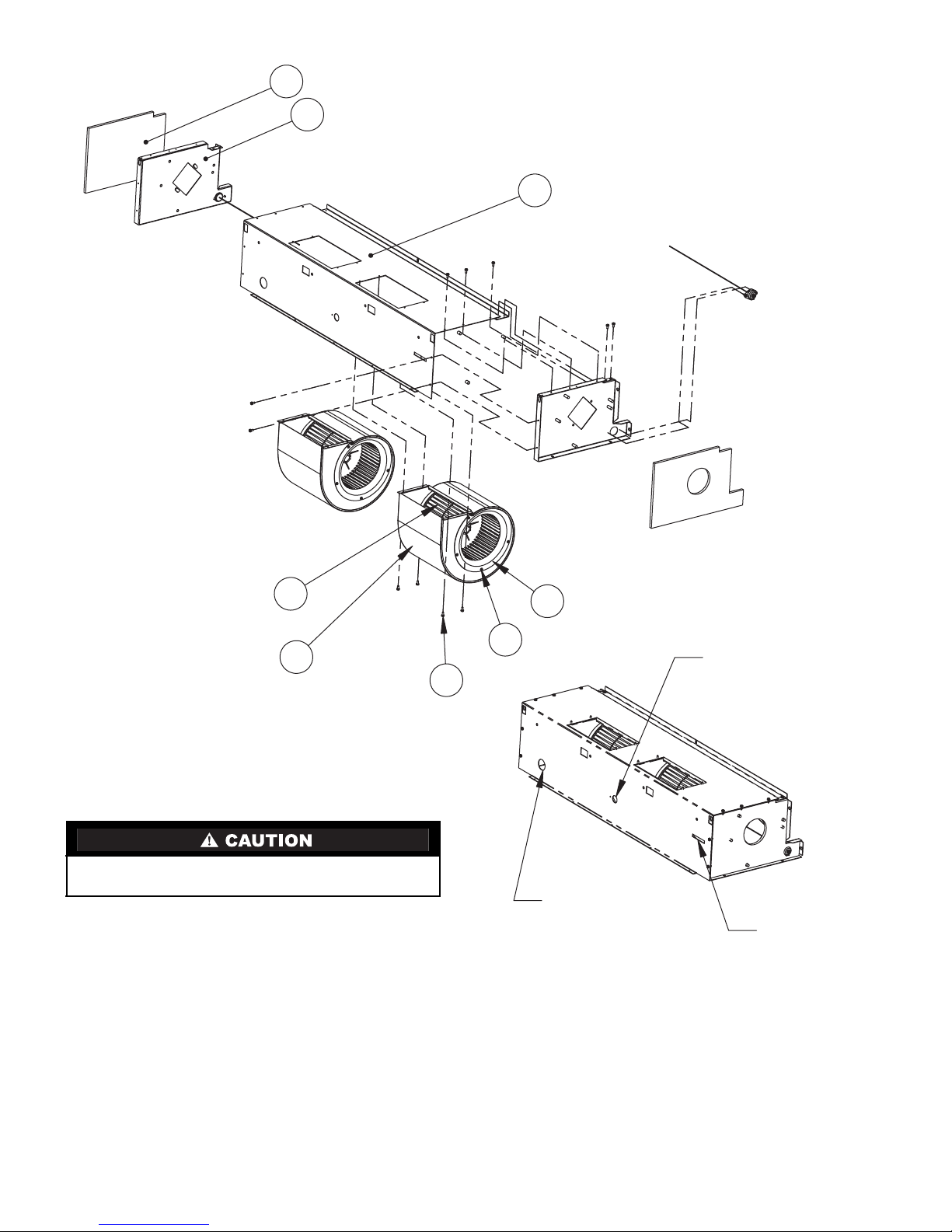
AUTOMATIC RESET
1
HIGH TEMPERATURE
LIMIT SWITCH
(SEE NOTES 2,3)
(SEE CAUTION)
2
3
8
4
MANUAL RESET
HIGH TEMPERATURE
LIMIT SWITCH
(SEE NOTES 2,3)
(SEE CAUTION)
5
7
6
DISCHARGE AIR
TEMPERATURE
SENSOR (OPTIONAL)
OPENING
t
DO NOT CHANGE LIMIT SWITCH CAPILLARY TUBE LOCATION! LIMIT SWITCHES MAY NOT FUNCTION PROPERLY.
NOTES:
1. Not all components shown for clarity.
2. Supplied on electric heat units only.
3. Secure capillary tubes to blower housing using high temperature
cable tie. Capillary tube lengths will vary depending on unit size.
Fig. 44 — 40UV,UH Ventilator Blower Section Assembly Sheet Metal (All Units)
64
RETURN AIR
TEMPERATURE
SENSOR (OPTIONAL)
OPENING
MOTOR AND
COUPLING
SETSCREW
ACCESS
Page 65
Damper Section Removal and Reinstallation
(Fig. 45)
Lock out and tag all power supplies to equipment and controls prior to servicing unit. Follow all safety codes. Failure
to do so could result in personal injury.
The assembly order of the bearing installation is critical. Be
careful with all components during removal and installation. Any excessive force applied to these components can
cause unintended damage and void unit warranty.
To remove damper section:
1. Turn off all power to unit.
IMPORTANT: Tag each right front panel (40UV) or
middle bottom panel (40UH) for each unit. Panels have
electrical information specific to each unit.
5
2. Use
3. Remove four carriage bolts and nuts securing kickplate to
/32in. hex (Allen) tool or3/8in. nut driver to remove
front (40UV) or bottom (40UH) panels and right end
panels.
end frames.
IMPORTANT: Tag kickplate for each unit. Kickplate
has electrical information specific to each unit.
4. Remove the two
1
/4in. head screws securing kickplate to
the damper sides (one on each side) and remove
kickplate.
5. Remove
1
/4in. head screws attaching outside air (OA)
actuator to damper shaft or attaching locking quadrant assembly to damper shaft. Remove OA actuator or locking
quadrant assembly.
1
6. Remove six
/4in. head screws (3 per side) securing
damper to 40UH unit rear panel.
7. Remove two
5
/16in. nuts attaching damper assembly to
back frame.
8. Remove damper assembly from unit.
To replace damper section:
1. Replace damper assembly into unit.
2. Replace
5
/16in. nuts attaching damper assembly to back
frame.
1
3. Replace six
/4in. head screws (3 per side) securing
damper to 40UH unit rear panel.
4. Replace
1
/4in. head screws attaching OA actuator to
damper shaft OR attaching locking quadrant assembly to
damper shaft. Replace OA actuator or locking quadrant
assembly.
1
5. Replace the two
/4in. head screws securing kickplate
to the damper sides (one on each side) and remove
kickplate.
6. Replace four carriage bolts and nuts securing kickplate to
end frames.
7. Reinstall front (40UV) or bottom (40UH) panels. Reinstall end panels. Ensure that tag on each right front
panel (40UV) or middle bottom panel (40UH) matches unit tag.
8. Restore power to the unit.
65
Page 66
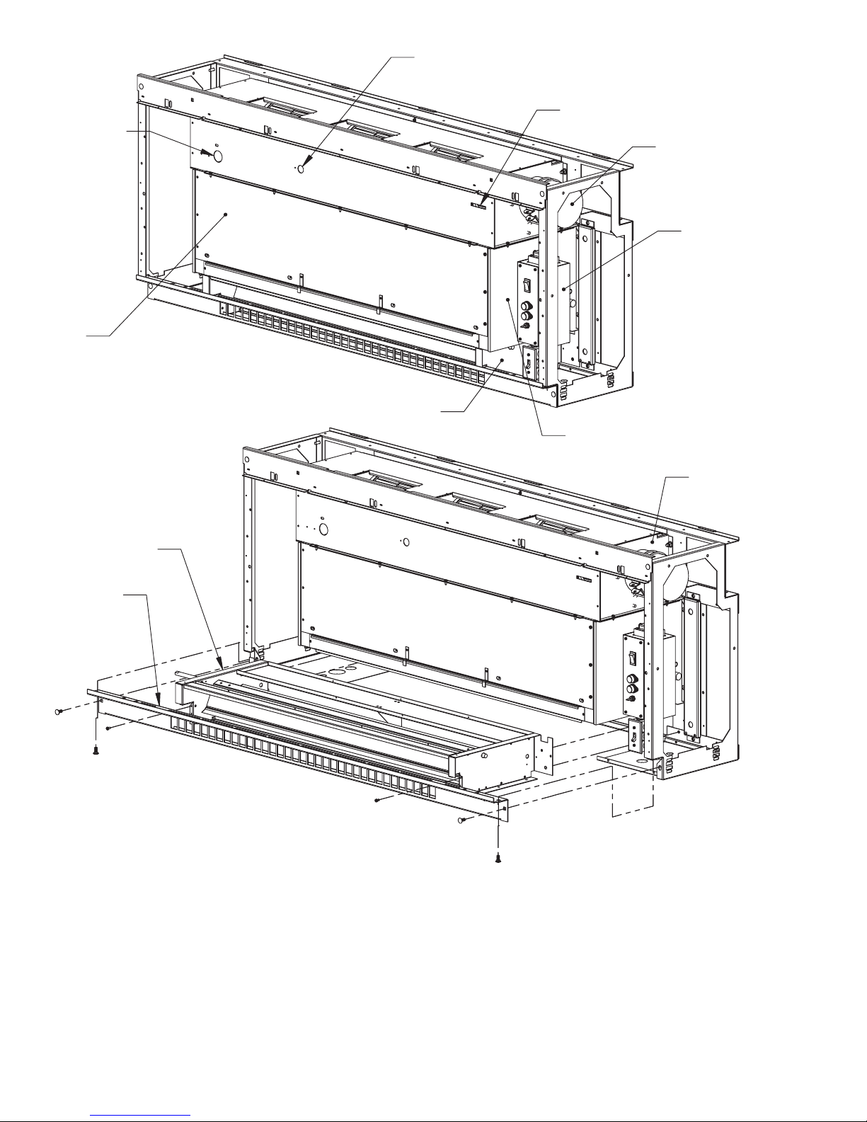
RETURN AIR
TEMPERATURE
SENSOR
OPENING
FRONT
COIL
BAFFLE
DISCHARGE AIR
TEMPERATURE SENSOR
OPENING
DAMPER SECTION
MOTOR & COUPLING
SETSCREW ACCESS
COIL SECTION
MOTOR
MOTOR
ELECTRICAL
BOX
DAMPER SECTION
KICKPLATE
NOTES:
1. Unit shown in vertical orientation. Drawing applies to horizontal and vertical units.
2. Not all components shown for clarity.
BLOWER SECTION
Fig. 45 — 40UV,UH Ventilator Damper Section Removal/Installation
66
Page 67
TESTING
The Unit Ventilator Comfort Control module is designed for
easy checkout and commissioning using the Carrier Comfort
Network® (CCN) Service Tool. An RJ14 service connector
jack is provided on each control board, which eliminates the
need to modify any communication wiring when service is
required. See Fig. 26.
Before any testing is performed, be sure all configuration
has been completed and the device address and bus number
have been changed from the factory defaults.
NOTE: No two devices should use the same address even if
they are not connected to the CCN system. The Comfort Controller uses this unique addressing to provide a restart delay
upon returning from a power failure and a start delay during
normal operation. This prevents excessive demand by staggering the start time for each piece of equipment using a Unit
Ventilator Comfort Controller.
To test the Comfort Controller, perform the following
procedure:
1. The controller database must be uploaded into the Network Service Tool which will be used to perform the
testing. This will allow access to all the necessary configuration and status information. Follow the operating
instructions provided with the service tool and perform
the controller upload.
2. With the control switch in the CONT position, apply
power to the control. Verify the red LED on the control
board flashes ON and OFF at a 1-second rate. It may
take up to 5 seconds for this to occur initially as the
control board is performing a self-health diagnostic
check. Verify the fan starts to operate.
3. Using the Network Service Tool, select the controller
to be tested from the menu provided, then select the
DISPLAY function.
4. Using a digital thermometer to initially check and verify the temperature sensor, check the temperature values for the space/return air sensor, the supply air
sensor, and the mixed air and outdoor-air sensors if
installed. If an error exists between the actual value
and the displayed reading, determine the difference
between the two values, and enter a set point Trim (see
Table 24) in the configuration table for the appropriate
sensor. No correction is required for the supply air sensor. If this sensor has more than a ± 5 degree F error,
replace the sensor.
5. Next, test the controller inputs and outputs as applicable. Verify that all modulating outputs are driven fully
closed after power has been applied to the controller
for at least 3 minutes. Verify that each water valve and
the outdoor-air damper are fully closed. Use the procedures below to test the inputs and outputs as applicable
to each control.
NOTE: The control drives all modulating outputs, which have
been configured, closed when first returning from a power failure restart, regardless of whether an output is normally open,
normally closed, or non-spring return type.
Water Valve Tests
The manual positioning lever on all water valves should
only be used when controller power is OFF. DO NOT
attempt to move this lever when controller power is
applied. If the position lever does not move freely for manual positioning when the power is off, remove the valve
cover and push the solenoid plunger down using a small
screwdriver inserted in the slot below the solenoid.
MODULATING COOLING CONTROL — If a modulating
chilled type water valve is used, verify that valve position is
fully closed while the unit is unoccupied and the fan is OFF.
Using the Network Service Tool, page down to the bottom of
the Points Display screen and select the COOLING 2 output.
Force the output to OFF. Next, select the COOLING 1 output
and force this output ON. Verify the chilled water valve begins
to open. Allow the valve to fully open and check to ensure the
valve reaches its full stroke and does not stick or bind. After the
valve has stopped opening, select the COOLING 2 output and
force it to ON. The force placed earlier on the COOLING 1
output should be removed automatically and the chilled water
valve should begin to close. After the valve has fully closed,
remove any forces from the COOLING 1 and COOLING 2
outputs.
HEATING VALVES — If a modulating hot water or steam
type heating valve is used, verify the position of the valve is
fully closed while the unit is unoccupied and the fan is OFF.
Using the Network Service Tool, page down to the bottom of
the Points Display screen and select the HEATING 2 output.
Force the output to OFF. Next, select the HEATING 1 output
and force this output ON. Verify the heating valve begins to
open. Allow the valve to fully open and check to ensure the
valve reaches its full stroke and does not stick or bind. After the
valve has stopped opening, select the HEATING 2 output and
force it to ON. The force placed earlier on the HEATING 1 output should be removed automatically and the heating valve
should begin to close. After the valve has fully closed, remove
any forces from the HEATING 1 and HEATING 2 outputs.
Face and Bypass Damper Tests
COOLING CONTROL — For units equipped with cooling,
verify that the face and bypass damper is in the full coil bypass
position when the unit is unoccupied and the fan is off. Verify
that the switch position indicator on the face and bypass damper actuator is pointing to the zero (0) position at this time.
Verify the cooling valve is closed.
Using the Network Service Tool, page down to the bottom
of the Status display screen and select the Heating Enable Output point. Force this output to OFF. Next, select the Cooling
Enable Output and force this point to ON. Select the COOLING 2 output and force this point to OFF. Select the COOLING 1 output and force this point to ON. Verify the face and
bypass damper begins to move toward the coil face position
and the cooling valve opens. Check to ensure the valve reaches
the full open position and the damper moves to the coil face position without sticking or binding. After the damper reaches the
full coil face position, select the COOLING 2 output and force
it to ON. The force placed earlier on the COOLING 1 output
should be removed automatically, and the damper should begin
moving toward the bypass position. After the face and bypass
damper is in the bypass position, force the Cooling Enable Output to OFF. Verify the cooling valve is closed or closing. After
the valve has fully closed, remove any forces from the COOLING 2, Heating Enable, or Cooling Enable Outputs.
HEATING CONTROL — For units equipped with heating,
verify that the face and bypass damper is in the full coil bypass
position when the unit is unoccupied and the fan is off. Verify
that the switch position indicator on the face and bypass damper actuator is pointing to the zero (0) position at this time.
Verify the heating valve is closed.
Using the Network Service tool, page down to the bottom of
the Points display screen and select the Cooling Enable Output
point. Force this output to OFF. Next, select the Heating Enable
Output and force this point to ON. Select the HEATING 2 output and force this point to OFF. Select the HEATING 1 output
and force this point to ON. Verify the face and bypass damper
begins to move toward the coil face position and the heating
valve opens. Check to ensure the valve reaches the full open
position and the damper moves to the coil face position without
67
Page 68

sticking or binding. After the damper reaches the full coil face
position, select the HEATING 2 output and force it to ON. The
force placed earlier on the HEATING 1 output should be removed automatically, and the damper should begin moving toward the bypass position. After the face and bypass damper is
in the bypass position, verify the heating valve is closing. After
the valve has fully closed, remove any forces from the HEATING 2, Heating Enable, or Cooling Enable Outputs.
Dampers
MODULATING OUTDOOR (OA) AIR DAMPER — Verify the position of the OA damper is fully closed off to outdoor
air when the unit is off or unoccupied. Using the Network Service Tool, page down to the bottom of the Status Display
screen and select the MIXED AIR DAMPER 2 output. Force
the output to OFF. Next, select the MIXED AIR DAMPER 1
output and force this output ON. Verify the dampers begin to
open to outdoor air while closing off the return air damper. Allow the dampers to fully open and check to ensure the outdoorair damper reaches its full open position and does not stick or
bind. After the damper has stopped opening, disconnect power
to the controller by setting the control to OFF. Verify the spring
return feature fully opens the return air damper while the outdoor-air damper fully closes. Return the control switch to
CONT and wait for the damper to again fully open to the outdoor air.
After the outdoor-air damper is fully open, select the
MIXED AIR DAMPER 2 output and force it to ON. The force
placed earlier on the MIXED AIR DAMPER 1 output should
be removed automatically. The outdoor-air dampers should begin to close while the return air damper begins to open. After
the outdoor-air dampers fully close, remove any forces from
the two outputs.
Fan Tests — The Unit Ventilator Comfort Control module
provides a fan relay output which starts and stops the fan when
the control switch is in the AUTO position. A three-speed output control is used to switch the fan from LOW speed to
MEDIUM or HIGH speed as required by the load.
FAN RELAY OUTPUT — Set the control switch to the
AUTO position and using the Network Service Tool, select the
Status Display screen and verify the FAN STATUS and FAN
RELAY both read OFF. Set the control switch to the AUTO
position. Select the FAN RELAY and force the point to ON.
Verify the fan starts and the FAN STATUS changes within
10 seconds. Reselect the FAN RELAY and force the point to
OFF. Verify the fan stops and the fan status changes to OFF.
Remove any force applied.
THREE-SPEED FAN — To verify proper operation of the
fan speed control, the unit must be in the Unoccupied mode.
With the fan stopped, set the control switch to the CONT position. Verify the fan operates at low speed. Using the Network
Service Tool, page down through the Maintenance screen and
locate the FAN SPEED RELAY 1 point. Force the FAN
SPEED RELAY 1 output to ON. Verify the fan speed increases
to MEDIUM. Select the FAN SPEED RELAY 2 output and
force this point to ON. Verify the fan speed increases to HIGH.
Remove any forces from FAN SPEED RELAY 1 and FAN
SPEED RELAY 2.
FAN STATUS — Set the control switch in the OFF position.
Using the Network Service Tool, select the Points Display
screen and verify the Supply Fan Status reads OFF. Set the control switch to the CONT position and verify the fan is operating. Verify the Supply Fan Status reads ON.
Filter Maintenance — For units connected to a CCN
system, a dirty filter alarm is generated and reported as soon as
the operating hours of the unit exceed the configured filter
maintenance interval. This is a software function of the controller and does not require any testing.
To reset the alarm after the filters have been serviced, use
the Network Service Tool and select the filter status from the
Status Display screen. Force the point to CLEAN. After waiting 10 seconds, remove the force using the AUTO command.
This will reset the timer and reset the displayed value to
CLEAN.
Remote Start Input — Set the control switch to the
OFF position and using the Network Service Tool, select the
Status Display screen and verify the FAN STATUS and FAN
RELAY both read OFF. Set the control switch to the AUTO
position. Using a jumper wire, temporarily jumper terminals
TB to T20 of the control board. Verify the FAN RELAY reads
ON, the fan starts and the FAN STATUS changes from OFF.
From the Status Display screen, determine the operating
MODE. Remove the jumper. If the operating mode previously
was cooling, the MODE will change to FAN ONLY as soon
as the jumper is removed. The fan will continue to operate for
5 minutes. For all other modes, the fan should stop within
5 seconds after the jumper is removed.
Sensors
AIR QUALITY SENSOR OPTION — Using the Network
Service Tool, select the Status Display screen and verify the
Air Quality (CO
the sensor is configured for a 2 to 10 vdc output over a 0 to
2000 ppm sensing range. The hardware jumper inside the sensor near the terminal connection block must also be installed in
the proper position for a voltage output. Any further sensor
checkout requires the use of the User Interface Program and a
calibration gas to provide an accurate verification. Refer to the
instructions provided in the calibration gas kit and the User Interface Program for operation of these items.
HUMIDITY SENSOR OPTION — Using the Network Service Tool, select the Status display screen and verify the Relative Humidity reads the proper value. Be sure the local RH sensor decision in the CCN Configuration table has been set to
YES. The 499-ohm resistor, which has been factory-supplied
with the sensor, must also be correctly installed. Use a sling
psychrometer or local humidity sensor to verify the sensor is
reading properly.
sensor) reads at least 300 ppm. Verify
2
Fire Shutdown Option — Using the Network Service
Tool, select the Status display screen and verify the Fire Shutdown status reads NORMAL when the local smoke or fire detector is in the normal state. Set the control switch to the AUTO
position, and force the FAN RELAY output ON. Verify the fan
start and the FAN STATUS reads ON. Trip the local smoke detector or fire detector and verify the Fire Shutdown input reads
ALARM, the supply fan immediately stops, and the FAN
STATUS reads OFF. Place the control switch in the CONT
position and verify the supply fan remains off. Reset the smoke
or fire detector and verify the supply fan restarts. Remove
all previous forces and set the control switch back to the OFF
position.
Electric Heat and Direct Expansion Cooling —
functions utilize both mechanical and software integrated safeties which prevent the testing of these functions independently
of the equipment operation. These require that the equipment
be operating in order to prevent equipment damage. All previous testing must be completed prior to performing any DX and
electric heat tests.
ELECTRIC HEAT — Set the control switch to the OFF position. Using the Network Service Tool, select the Status Display
screen and verify the FAN STATUS and FAN RELAY both
read OFF. Verify a controlling temperature of 85 F or less. If
not, force the value to 70 F. Set the control switch to the AUTO
position. Select the Remote Start point and force the point to
ON. Verify the fan starts and the FAN STATUS changes. Select
the Set Point screen and increase the Occupied Switch Set
Electric heat and direct expansion cooling control
68
Page 69
Point to 90 F. Select the Points Display screen and verify the
Heating 1 output reads ON. If two stages are used, verify the
second stage is set to ON within two minutes. Verify both electric heat control relays are energized. Verify the electric heater
stage(s) are enabled and that the supply-air temperature increases. Select the Set Point screen and return the set points to
their original values. Reselect the Remote Start input and set
the point to AUTO. Verify the supply fan stops and the Fan Status changes to OFF. Reselect the Controlling Temperature
point and AUTO this point if it had previously been forced.
DIRECT EXPANSION COOLING — Set the control switch
to the OFF position and the condensing unit disconnect to OFF.
Using the Network Service Tool, select the Points Display
screen and verify the FAN STATUS and FAN RELAY both
read OFF. Verify the Controlling Temperature is greater than
55 F. If not, force the value to 70 F. Set the control switch to the
AUTO position. Select the Remote Start point and force the
points to ON. Verify the fan starts and the FAN STATUS
changes. Select the Set Point screen and decrease the Occupied
Heating Set point to 40 F and decrease the Occupied Cooling
set point to 45 F. Verify the outdoor-air temperature reads
above the configured DX Outdoor Air Lockout value. If not,
force the Outside-Air Temperature to 90 F. Select the Points
Display screen and verify the Cooling 1 output reads ON. If
two stages are used, verify the second stage is set to ON within
2 minutes. Verify both accessory relays are energized. Set the
condensing unit disconnect to ON. Verify the DX cooling
stage(s) are enabled and that the supply-air temperature
decreases. Allow the unit to operate for 2 minutes minimum.
Select the Set Point screen and return the set points back to
their original values. Reselect the Remote Start input and
AUTO the point. Verify the mode changes to Fan Only. Reselect the Controlling Temperature point and AUTO this point
if it had previously been forced. Reselect the Outside-Air
Temperature point and AUTO this point if it had previously
been forced. Allow the fan to operate to evaporate the condensate from the coil. The supply fan will stop automatically after
approximately 5 minutes.
Mixed-Air Damper Sensor Final Calibration — The mixed-air damper control uses a temperature dif-
ference method to maintain the minimum outdoor-air ventilation. For this reason, it is important that the sensors be calibrated to ensure that the desired quantity of outdoor air is provided
at any operating speed.
IMPORTANT: The Comfort Controller requires that
each unit be equipped with its own outdoor-air sensor
installed for mixing box applications. A broadcasted
OAT value from a single location will not ensure that the
outdoor-air temperature is being correctly measured for
an individual unit.
To perform a final calibration for the sensors:
1. Set the control switch to the OFF position and using
the Network Service Tool, select the Display screen
and verify the FAN STATUS and FAN RELAY both
read OFF.
2. Set the control switch to the CONT position.
3. Using the Network Service Tool, page down to the
bottom of the Points Display screen and select the
MIXED-AIR DAMPER 2 OUTPUT. Force the output
to OFF.
4. Next, select the MIXED-AIR DAMPER 1 output and
force this output ON. Wait for the dampers to fully
open to outdoor air while closing off the return-air
damper. Allow the unit to operate for 5 minutes after
the OA damper reaches its fully open position.
5. Verify the mixed-air temperature is within 0.3° F of
the outdoor-air temperature value. Using the OAT
(Fig. 24) function, adjust the Outdoor-Air Value so that
both sensors read the same relative temperature. (The
values should have been previously verified for accuracy earlier.)
6. Select the MIXED AIR DAMPER 2 output and force
it to ON. The force placed earlier on the MIXED-AIR
DAMPER 1 output should be removed automatically
and the OA dampers should begin to close while the
return-air damper begins to open.
7. After the OA dampers fully close, allow the unit to
operate for 5 minutes. Verify the return-air temperature
is within 0.3° F of the mixed-air temperature reading.
If not, adjust the return-air temperature reading using
the OAT (Fig. 24) function so that both sensors read
thesametemperature.(Thevalueofthemixed-air
temperature and outdoor-air temperature were previously trimmed and should not be readjusted.)
8. Reselect the FAN RELAY and force the point to OFF.
Verify the fan stops and the FAN STATUS changes to
OFF. Remove the forces previously placed on the
MIXED-AIR DAMPER 1 and 2 outputs.
Testing Completion — After all checkout and testing
has been completed, set the controller time by using the Building Time feature of the Network Service Tool (do NOT use the
Controller Time Function). After disconnecting from the unit,
CYCLE THE UNIT POWER to reset the valve and damper
positions and restore automatic control. Although the Unit
Ventilator Comfort Control module will not respond, the
controller will begin to maintain a software clock so that any
Network Alarm message will contain the correct time and date
stamp.
Additionally, the database for each control should be stored
on a 3.5 in. computer disk for future service use. The CCN Network Service provides an Export function for this. Refer to the
Service Tool operating instructions for further information. The
database disk will provide an easy method of reprogramming a
control board should it ever become necessary to replace it. All
the control configuration, set points, sensor trim information,
and controller addressing information is stored for easy downloading into a replacement control board assembly.
Unit Diagnostics and Troubleshooting — See
Table 30 for 40UV,UH diagnostics and troubleshooting
information.
69
Page 70
Table 30 — Unit Diagnostics And Troubleshooting
PROBLEM POSSIBLE CAUSE CORRECTIVE ACTION
Unit Does Not Operate Power to control is OFF Check local disconnect or circuit breaker.
No Heating Heating is forced disabled Verify no forces are present in the Heating 1, Heating 2 or
No Cooling Cooling is forced disabled Verify no forces are present in the Cooling 1, Cooling 2 or
Overheating Heat outputs are forced Verify no forces are present on the Heating 1 or Heating 2
Overcooling Cooling outputs are forced Verify no forces are present on the Cooling 1 or Cooling 2
Mixed Air Damper Will
Not Operate
Damper Fails to Operate
Properly at Minimum
Position
Temperature Sensor Not
Reading Correctly
Remote Start/Stop (S/S)jumper not installed (for
stand-alone operation only)
Faulty connections Check LED on control board. If not flashing at a 1-second
Control switch is in OFF position or safety controls
are tripped
Smoke or fire detector is tripped, detector wiring
shorted
No hot water/steam/electricity Check source and correct any problems.
Electric heater safety tripped Determine cause for safety trip, typically insufficient air-
Configuration error Verify the control is configured properly for the type of
No power to valve or relays Check for 24 vac at water valve. If no power, check for
End switch improperly set (on Face and Bypass
units only)
Incorrect sensor reading Verify the temperature sensors are reading the correct
No fan status Verify the Fan Status reads ON. Fan Status must read ON
No chilled water/electricity Check source and correct any problems.
Condensing unit safety tripped Determine cause for safety trip, correct condition and
Configuration error Verify the control is configured properly for the type of
No power to valve or relays Check for 24 vac at water valve. If no power, check for
Outdoor air temperature below DX outdoor air lockout
End switch improperly set (on Face and Bypass
units only)
Incorrect sensor reading Verify the temperature sensors are reading the correct
No fan status Verify the Fan Status reads ON. Fan Status must read ON
Configuration error Verify the control is configured properly for the type of
Configuration error Verify the control is configured properly for the type of
Dampers are forced Verify no forces are present on the MIX1orMIX2 outputs.
No power to actuator Check for 24 vac. If no power, check for open wiring.
Configuration error Verify the control is properly configured for modulating
Failed sensor (shortened or open) Verify the temperature sensors are reading correctly.
No fan status Verify the Fan Status reads ON. Fan Status must read ON
Incorrectly calibrated sensors Verify sensors are properly calibrated (refer to the test
Loose connections Verify all sensor lead connections are securely fastened.
Sensor out of calibration Recheck each sensor reading using a digital thermometer
Install jumper between T20 on control module and TB
(24 vac).
rate, check for loose connections and 24 vac on POWER
connector.
Verify control switch is in the AUTO or CONT position.
Check for a tripped LLT.
Check the status of the Fire Shutdown input. Determine
cause of detector trip and correct if necessary. Check for
shorted wiring and correct if necessary.
Heating Enable outputs; remove if necessary.
flow. Correct condition and reset safety switch in heater
control box.
heat used.
open wiring.
Refer to Face and Bypass Damper testing to verify proper
operation of end switch and water valves.
temperatures.
for heat to operate.
Heating Enable outputs; remove if necessary.
reset safety switch in condensing unit control box.
cooling used.
open wiring.
Ver if y D XOutdoor Air Lockout is correctly set to the mini-
mum recommended condensing unit operating temperature. Verify OAT sensor is reading correctly.
Refer to Face and Bypass Damper Tests to verify proper
operation of end switch and water valves.
temperatures.
for cooling to operate.
outputs. Remove if necessary.
heating used.
outputs. Remove if necessary.
cooling used.
Remove if necessary.
type OA damper.
Replace any bad sensor.
for dampers to operate.
section and repeat the calibration procedure).Verifyno
forces are present on MAT, OAT, o r S P T.
as a reference. Reset the TRIM value to zero before testing each sensor (OAT, MAT, and RAT/SPT). Replace any
sensor requiring more than 5 degrees of correction.
70
Page 71
Table 30 — Unit Diagnostics and Troubleshooting (cont)
PROBLEM POSSIBLE CAUSE CORRECTIVE ACTION
Indoor Air Quality (IAQ)
Features Malfunctioning
LLT Trips Frequently LLT switch malfunctioning Replace LLT switch.
IAQ Level Exceeds
Set Point Frequently
(Generated Alarms)
LEGEND
DX — Direct Expansion
IAQ — Indoor Air Quality
LED — Light Emitting Diode
LLT — Low-Limit Thermostat
MAT — Mixed-Air Temperature Sensor
MIX1 — Mixed Air 1Terminal
MIX2 — Mixed Air 2 Terminal
OA — Outdoor Air
OAT — Outdoor-Air Temperature Sensor
RH — Relative Humidity
RAT — Return-Air Temperature
SPT — Space Temperature Sensor
TB — Terminal Box
IAQ not enabled Enable IAQ control operation.
Set point too high/too low Adjust the set point to the correct value.
Space or return air temperature too high/low Control will resume when space/returns temperatures
Space Relative Humidity too high Control will resume when relative humidity recovers.
MAT sensor is shorted, open, or forced Normal operation will resume when MAT sensor is
MAT sensor failed or out of calibration Verify MAT sensor is reading correctly. Trim or replace if
Maximum output value set too low Verify maximum output value has been correctly set.
OAT sensor failed or open Normal operation will resume when OAT sensor is
recover.
Verify high humidity limit is configured properly. Reset to
100% if RH control is not used.
operating properly. Remove Force; repair or replace MAT
sensor.
necessary.
Increase value in 10% increments.
repaired.
71
Page 72

Copyright 2005 Carrier Corporation
Manufacturer reserves the right to discontinue, or change at any time, specifications or designs without notice and without incurring obligations.
Book 3
Ta b 2 a
Catalog No. 534-094 Printed in U.S.A. Form 40UV,UH-6SI Pg 72 1-06A 7-05 Replaces: 40UV,UH-3SI
 Loading...