

Carrier UH075, 40UV, UH125, UH150, 40UH200 Installation, Start-up And Service Instructions Manual
...Page 1
40UV,UH050-200
Unit Ventilators
Installation, Start-Up and Service Instructions
CONTENTS
Page
SAFETY CONSIDERATIONS .........................1
INTRODUCTION .....................................1
PREINSTALLATION..................................1
Unpack and Inspect Units ...........................1
Protect Units From Damage .........................1
Prepare Jobsite for Unit Installation .................1
Identify and Prepare Units ...........................1
PHYSICAL DATA...................................1,2
INSTALLATION ...................................2-24
Placing Vertical Units in Position ....................2
Placing Horizontal Units in Position .................2
Make Piping Connections ...........................8
Make Electrical Connections ........................8
Actuators (Field-Supplied)...........................8
Make Duct Connections ............................23
Make Final Preparations ............................24
START-UP ..........................................24
SERVICE ........................................25-41
Preventing Excessive Condensation on Unit .......25
Check Drain ........................................25
Fan Motor Bearings ................................25
Fan Shaft Ball Bearing..............................25
Clean Fan Wheel ...................................25
Clean or Replace Air Filters ........................25
ECM Motor Removal and Reinstallation ............25
Blower Assembly Section Removal and
Reinstallation ....................................27
Coil Assembly Removal and Reinstallation .........30
Ball Bearing Replacement ..........................32
Sleeve Bearing Replacement .......................37
Blower Wheel Removal and Reinstallation..........39
Damper Section Removal and Reinstallation .......40
SAFETY CONSIDERATIONS
Installation and servicing of this unit can be hazardous due
to system pressure, electrical components and equipment location (such as a ceiling or elevated structure). Untrained personnel can perform the basic maintenance functions of replacing
filters. Only trained and qualified service personnel should perform all other operations.
When installing this unit, observe precautions in the literature, tags and labels attached to the equipment, and any other
safety precautions that may apply.
• Follow all safety codes.
• Wear safety glasses and work gloves.
• Use care in handling and installing this accessory.
• Use quenching cloth for all brazing operations.
• Have fire extinguisher available for all brazing
operations.
INTRODUCTION
This document contains general installation instructions for
the 40UV,UH unit ventilators. Refer to the 40UV,UH Unit Ventilators with Product Integrated Controls (PIC) Installation,
Start-Up and Service instructions manual for specific PIC
control instructions. Refer to the unit wiring diagram or to
specific manufacturer literature for any other type of factorymounted controls.
See submittal drawings for unit configurations, dimensions,
clearances, and pipe connections. Refer to unit wiring label for
all electrical connections; follow NEC (National Electrical
Code) and local codes.
PREINSTALLATION
Unpack and Inspect Units —
from all units. Check the shipment against shipping order. If
shipment is damaged or incomplete, file claim with transportation company and advise Carrier immediately.
Remove shipping wraps
Protect Units From Damage — To maintain war-
ranty, protect units against adverse weather, theft, vandalism,
and debris on jobsite. Do not allow foreign material to fall into
drain pan. Prevent dust and debris from being deposited on
motor and fan wheels.
If the equipment is stored for any length of time before installation, it should remain in its shipping container in a clean,
dry, and climate controlled area.
Prepare Jobsite for Unit Installation — To save
time and to reduce the possibility of costly errors, set up a complete sample installation in a typical room at jobsite. Check all
critical dimensions such as pipe, wire, and duct connection
requirements. Refer to job drawings and product dimension
drawings as required. Instruct all trades in their part of the
installation.
Identify and Prepare Units
1. Be sure power requirements match available power
source. Refer to the unit nameplate and wiring diagram.
2. Remove front (40UV) or bottom (40UH) access panels
from the unit. Retain the
panels for reinstallation later.
3. Rotate the fan shaft by hand to ensure that fans are
unrestricted and can rotate freely. Check for shipping
damage and fan obstructions.
5
/32-in. socket head fasteners and
PHYSICAL DATA
Component weight data of 40UV,UH units is provided in
Table 1.
Before performing service or maintenance operations, turn
off main power switch to the unit. Electrical shock could
cause personal injury.
Manufacturer reserves the right to discontinue, or change at any time, specifications or designs without notice and without incurring obligations.
Book 3
Ta b 2 a
Catalog No. 534-095 Printed in U.S.A. Form 40UV,UH-7SI Pg 1 5-05 Replaces: 40UV,UH-2SI
Page 2
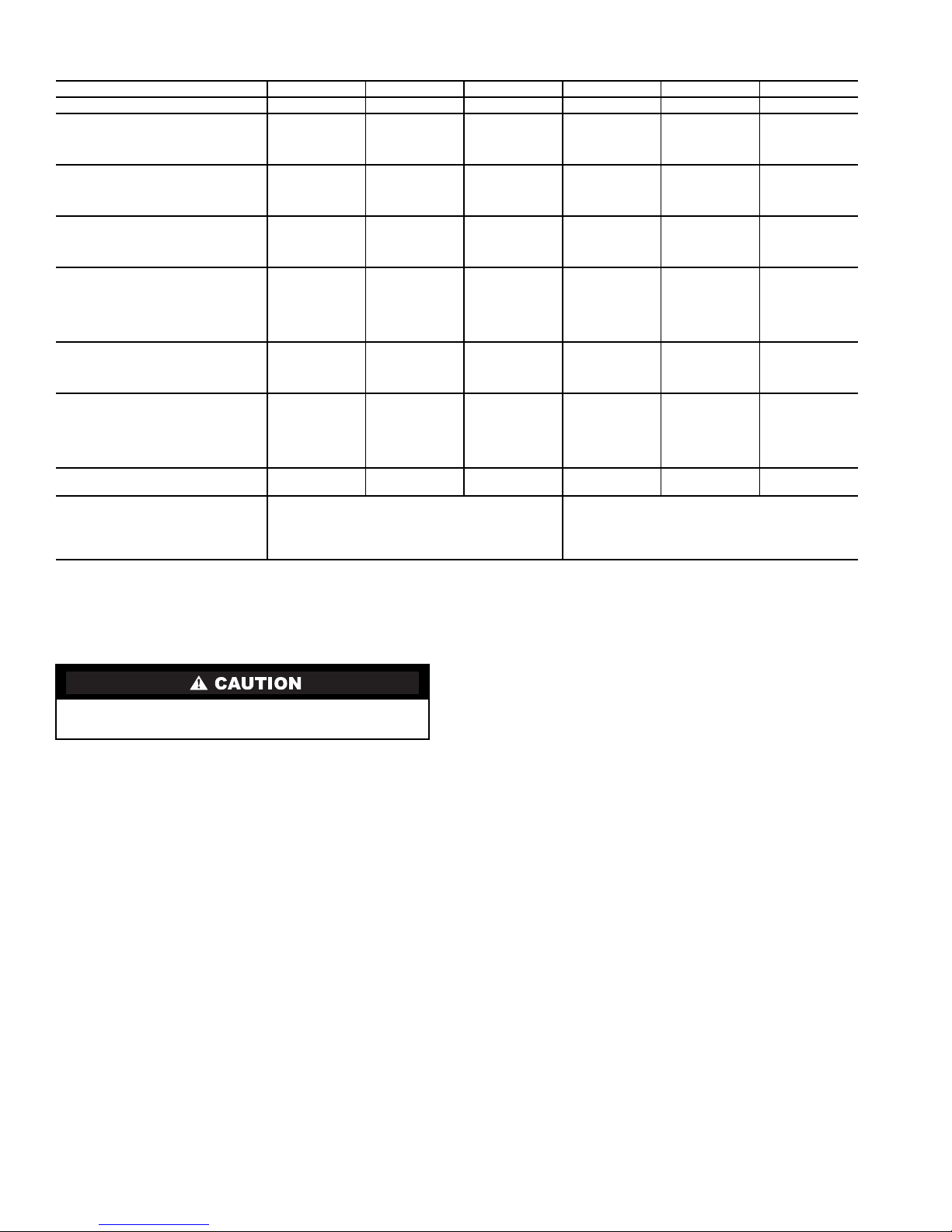
Table 1 — Physical Data
UNIT 40UV,UH 050* 075 100 125 150 200†
NOMINAL AIRFLOW (Cfm) 500 750 1000 1250 1500 2000
FANS
Quantity 123455
Diameter (in.) 8.32 8.32 8.32 8.32 8.32 9.5
Width (in.) 888886
FILTERS
Nominal Size (in.) (1 in. thick) 9
Nominal Size (in.) (2 in. thick) 9x 241/
Quantity 111111
40UV SHIPPING WEIGHT**
(Approx lb)
5
/8in. Deep Unit 330 400 480 590 660 —
16
7
/8in. Deep Unit 340 410 490 605 675 —
21
40UH SHIPPING WEIGHT**
(Approx lb)
1
/2in. Deep Unit — 420 500 620 690 —
30
36 in. Deep Unit — 500 600 740 830 —
40 in. Deep Unit — 530 640 790 880 1020
44 in. Deep Unit —————1050
40UV INSTALLED WEIGHT**
(Approx lb)
5
16
/8in. Deep Unit 315 380 460 570 640 —
7
/8in. Deep Unit 325 390 470 595 655 —
21
40UH INSTALLED WEIGHT**
(Approx lb)
1
/2in. Deep Unit — 405 480 600 670 —
30
36 in. Deep Unit — 485 580 720 810 —
40 in. Deep Unit — 515 620 770 860 1000
44 in. Deep Unit —————1030
COIL WATER WEIGHT
(Approx lb per row of coil)
COIL CONNECTIONS (in. OD) Return Supply
Water Coils with 1 to 5 Rows
Steam Coils (All Units)
DX Coils
LEGEND
DX — Direct Expansion
3
/4x241/
4
4
1.01.52.02.42.72.7
93/4x361/
4
9x361/
4
7
/
8
7
/
8
Suction Liquid
7
/
8
93/4x481/
*40UV only.
†40UH 40 and 44 in. deep units only.
**Weight based on damper-controlled unit with 5-row coil and factory-
4
9x481/
4
installed controls.
93/4x601/
9x601/
4
4
93/4x721/
9x721/
11/
4
4
7
/
8
8
3
/
8
93/4x721/
9x721/
4
4
INSTALLATION
Units must be installed level and plumb. Failure to do so
may result in excessive vibration and/or premature failure.
Placing Vertical Units in Position
1. Select the unit location; ensure that service clearance is
provided. Allow enough grille clearance to maintain
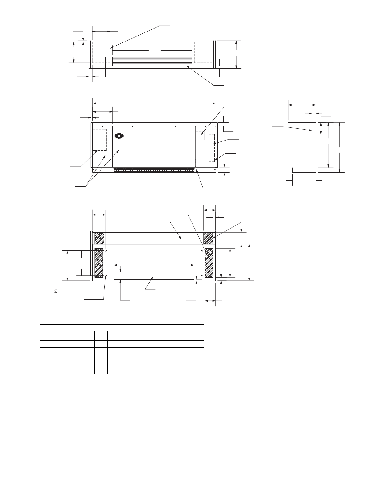
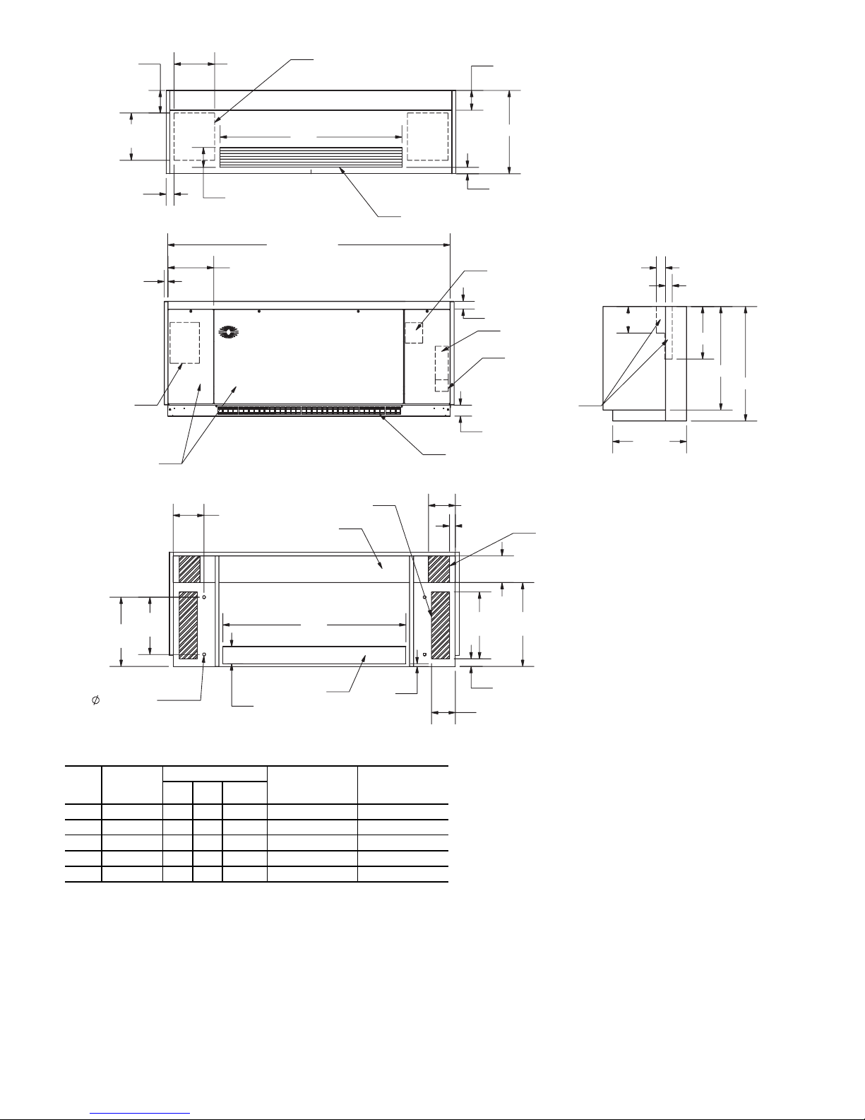
un-restricted airflow. See submittal drawings and Fig. 1
and 2 for dimensions.
2. Make sure wall behind unit is smooth and plumb; if
necessary, install furring strips on walls with irregular
surfaces or mullions. Furring strips must be positioned
behind mounting holes in unit. Fasteners, furring strips,
and other seals (if required) must be field supplied.
3. Remove all wall and floor moldings from behind the unit.
4. Move unit into position. Unit must be snug against wall
and furring strips.
5. Adjust unit leveling legs so unit is level. Unit must be
level for proper operation and condensate drainage.
6. Using field-supplied fasteners, reach into unit and attach
unit to the wall using the
back panel.
7. Protect the unit from jobsite debris. Do not allow foreign
material to fall into drain pan. Prevent dust and debris
from being deposited on motor or fan.
3
/4in. mounting holes in the
Placing Horizontal Units in Position
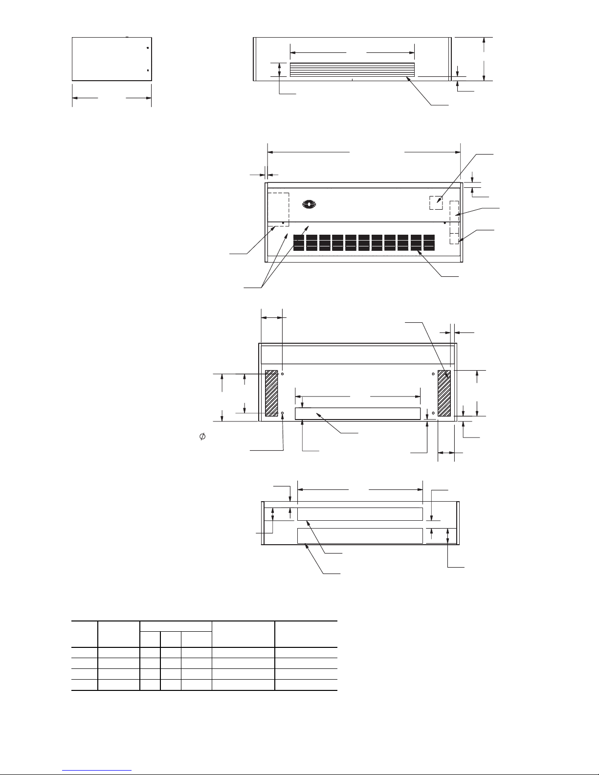
1. Select the unit location; ensure that service clearance is
provided. Allow enough grille clearance to maintain unrestricted airflow. Make sure that ceiling is able to support
the weight of the unit. See Fig. 3-5 for nominal unit weight.
See submittal drawings and Fig. 3-5 for dimensions.
NOTE: See page 23 for additional requirements regarding units ducted to multiple openings.
2. Ensure that bottom panels have been removed from unit.
When unit is lifted, access to the
through the bottom of the unit. Hanger rods and fasteners
and other required hardware must be field supplied.
3. Using a forklift or other mechanical lifting device, raise
the unit to the mounting position. If forklift or other
lifting device is likely to contact a painted wall surface,
protect the surface as necessary.
4. Use rods and fasteners to suspend the unit at the
mounting holes on the top of the unit. The unit must be
suspended at the
3
/4in. mounting holes; do not use any
other locations.
5. If desired, install field-supplied vibration isolators. Adjust
isolators so unit is uniformly suspended and pitched.
6. To ensure proper drainage and operation, ensure unit is
level and tighten all fasteners. DO NOT mount the unit
on a slope. Pitch of horizontal suspended units can
change after coil is filled; recheck after filling coil.
7. Protect the unit from jobsite debris. Do not allow foreign
material to fall into drain pan. Prevent dust and debris
from being deposited on motor or fan.
3
/4in. mounting holes is
2
Page 3
.78
(TYP)
10.61
(TYP)
REMOVABLE BOTTOM PANEL
(EACH END)
12.37
(TYP)
2.08
(TYP)
(UNIT SHOWN
WITH 1.00" END
CCN
CONTR
(OPTIONAL)
FRONT SERVICE
PANELS
(SEE NOTE 3)
1.00
PANELS)
OLLER
5.22
12.10 (TYP)
8.08
(TYP-SEE
NOTE 2)
W3
TOP VIEW
W1
(SEE NOTE 2)
FRONT VIEW
REMOVABLE PANEL
(
EACH END)
PIPE TUNNEL
16.63
1.70
BARSTOCK
DISCHARGE GRILLE
MOTOR
PIPING
2.00
RECESSED RETURN
AIR/KICK PANEL
7.04 (TYP)
1.54 (TYP)
7.00 (TYP)
TUNNEL
ELECTRICAL
BOX
NON-FUSED
DISCONNECT
SWITCH
2.95
PIPING ACCESS
OPENING
(EACH END)
16.63
2.40
13.90
7.02
27.30
30.00
RIGHT SIDE VIEW
(MOUNTING
HOLES-TYP4 PLACES)
UNIT
40UV
18.25
(TYP)
.75
AIRFLOW
(cfm)
15.00
(TYP)
4.50
DIMENSIONS (in.) APPROXIMATE
W1 W2 W3
WEIGHT (lb)
W2
REAR VIEW
SHIPPING
OUTSIDE AIR
OPENING
.90
APPROXIMATE
INSTALLED
WEIGHT (lb)
050 500 50 24 16.60 330 315
075 750 62 36 31.67 400 380
100 1000 74 48 46.74 480 460
125 1250 86 60 61.81 590 570
150 1500 98 72 78.47 660 640
Fig. 1 — 40UV Dimensions — 165/8-in. Deep Units
(Standard)
17.50
6.75 (TYP)
(TYP)
22.00
(TYP)
2.00
(TYP)
LEGEND
CCN — Carrier Comfort Network®
NOTES:
1. All dimensions are in inches.
2. Dimension does not include end panels.
3. Three front panels provided for service access.
4. Motor and electrical power input box on right side of
unit. Box includes fan speed switch, On/Off switch and
non-fused disconnect switch.
5. Connection hand is determined by facing discharge of
unit.
3
Page 4
5.98
(TYP)
10.61
(TYP)
REMOVA BLE BOTTOM PANEL
(EACH END)
5.20
12.37
(TYP)
2.08
(TYP)
(UNIT SHOWN
WITH 1.00" END
CCN
CONTROLLER
(OPTIONAL)
1.00
PANELS)
FRONT SERVICE
PANELS
(SEE NOTE 3)
5.22
12.00 (TYP)
8.08
(TYP-SEE
NOTE 2)
W3
TOP VIEW
W1
(SEE NOTE 2)
FRONT VIEW
REMOVABLE PANEL
(EACH END)
PIPE TUNNEL
STOCK
BAR
DISCHARGE GRILLE
MOTO R
2.00
3.00
RECESSED RETURN
AIR/KICK PANEL
7.04 (TYP)
1.54 (TYP)
7.00 (TYP)
21.88
1.70
ELECTRICAL
BOX
NON-FUSED
DISCONNECT
SWITCH
PIPING ACCESS
OPENING
(EACH END)
PIPING
TUNNEL
2.40
1.74
7.02
13.75
27.30
30.00
19.37
END VIEW
(MOUNTING
HOLES-TYP4 PLACES)
UNIT
40UV
15.00
18.25
(TYP)
.75
AIRFLOW
(cfm)
(TYP)
4.50
DIMENSIONS (in.) APPROXIMATE
W1 W2 W3
W2
OUTSIDE AIR
OPENING
REAR VIEW
SHIPPING
WEIGHT (lb)
0.90
APPROXIMATE
INSTALLED
WEIGHT (lb)
050 500 50 24 16.60 340 325
075 750 62 36 31.67 410 390
100 1000 74 48 46.74 490 470
125 1250 86 60 61.81 605 595
150 1500 98 72 78.47 675 655
Fig. 2 — 40UV Dimensions — 217/8-in. Deep Units
(With Piping Chase)
17.50
(TYP)
6.75 (TYP)
22.00
(TYP)
2.00
(TYP)
LEGEND
CCN — Carrier Comfort Network®
NOTES:
1. All dimensions are in inches.
2. Dimension does not include end panels.
3. Three front panels provided for service access.
4. Motor and electrical power input box on right side
of unit. Box includes fan speed switch, On/Off
switch and non-fused disconnect switch.
5. Connection hand is determined by facing discharge of unit.
4
Page 5
W3
16.63
30.50
LEFT SIDE VIEW
(UNIT SHOWN
WITH 1.00" END
CCN
CONTROLLER
(OPTIONAL)
BOTTOM SERVICE
PA NELS
(SEE NOTE 3)
1.00
PANELS)
5.22
8.08
(TYP-SEE
NOTE 2)
FRONT VIEW
W1
(SEE NOTE 2)
BOTTOM VIEW
REMOVABLE PANEL
(EACH END)
1.70
BARSTOCK
DISCHARGE GRILLE
(OPTIONAL)
MOTOR
2.00
ELECTRICAL
BOX
NON-FUSED
DISCONNECT
SWITCH
RETURN AIR
LOUVER
(OPTIONAL)
ED PA NEL
1.54
(TYP)
15.00
18.25
(TYP)
(TYP)
.75
(MOUNTING
HOLES-TYP4 PLACES)
2.27
5.00
LEGEND
CCN — Carrier Comfort Network®
UNIT
AIRFLOW
40UH
075 750 62 36 31.67 420 405
100 1000 74 48 46.74 500 480
125 1250 86 60 61.81 620 600
150 1500 98 72 78.47 690 670
(cfm)
DIMENSIONS (in.) APPROXIMATE
W1 W2 W3
SHIPPING
WEIGHT (lb)
APPROXIMATE
INSTALLED
WEIGHT (lb)
W2
OUTSIDE AIR
OPENING
4.50
1.00
TOP VIEW
W2
REAR OUTSIDE
AIR OPENING (OPTIONAL)
REAR RETURN
AIR OPENING (OPTIONAL)
REAR VIEW
NOTES:
1. All dimensions are in inches.
2. Dimension does not include end panels.
3. Two bottom panels provided for service access.
4. Motor and electrical power input box on right side of
unit. Box includes fan speed switch, On/Off switch and
non-fused disconnect switch.
5. Connection hand is determined by facing discharge of
unit.
17.50
(TYP)
2.50
(TYP)
6.75 (TYP)
3.00
5.75
Fig. 3 — 40UH Dimensions — 301/2-in. Deep Units
5
Page 6
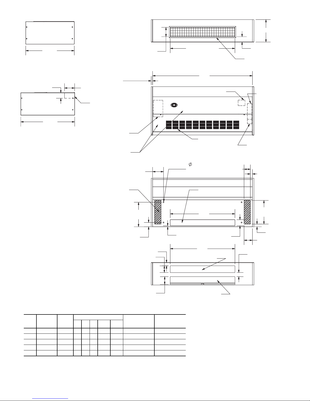
16.63
)
T
L
L
36.00
LEFT SIDE VIEW
(SIZES 075 TO 150)
4.00
40.00
LEFT SIDE VIEW
(SIZE 200)
(UNIT SHOWN
7.50
WITH 1.00"
END PANELS)
PIPE
TUNNEL
CCN
CONTROLLER
(OPTIONAL)
BOTTOM SERVICE
PA NEL S
(SEE NOTE 3)
REMOVABLE PANEL
(EACH EN
D)
1.00
W5
(OPENING)
8.00
(TYP-SEE
NOTE 2)
W3 (OPENING)
FRONT VIEW
W1
(SEE NOTE 2)
MOTOR
RETURN AIR
LOUVERED PANEL
(OPTIONAL)
BOTTOM VIEW
.75
(MOUNTING HOLESTYP-4 PLACES)
TOP OUTSIDE AIR
OPENING (OPTIONAL)
DOUBLE DEFLEC
DISCHARGE GRIL
(OPTIONAL)
NON-FUSED
DISCONNECT
SWITCH
4.75
(TYP)
4.00
(TO OPENING
ELECTRICA
BOX
1.00 (TYP)
W4
(TYP)
3.67
(TYP)
2.27
5.00
LEGEND
CCN — Carrier Comfort Network®
UNIT
AIRFLOW
40UH
(cfm)
075 750 36 62 36 36 18.67 7.00 500 485
100 1000 36 74 48 48 18.67 7.00 600 580
125 1250 36 86 60 60 18.67 7.00 740 720
150 1500 36 98 72 72 18.67 7.00 830 810
200 2000 40 98 72 72 26.92 10.00 1020 1000
DEPTH
(in.)
DIMENSIONS (in.) APPROXIMATE
W1 W2 W3 W4 W5
SHIPPING
WEIGHT (lb)
5.75
APPROXIMATE
INSTALLED
WEIGHT (lb)
W2
1.25
REAR OUTSIDE AIR
OPENING (OPTIONAL)
REAR RETURN AIR
OPENING (OPTIONAL)
TOP VIEW
W2
REAR VIEW
NOTES:
1. All dimensions are in inches.
2. Dimension does not include end panels.
3. Two bottom panels provided for service
access.
4. Motor and electrical power input box on
right side of unit. Box includes fan speed
switch, On/Off switch and non-fused disconnect switch.
5. Connection hand is determined by facing
discharge of unit.
4.50
17.50
(TYP)
2.50
(TYP)
6.75 (TYP)
3.00
Fig. 4 — 40UH Dimensions — Front Discharge Units
6
Page 7
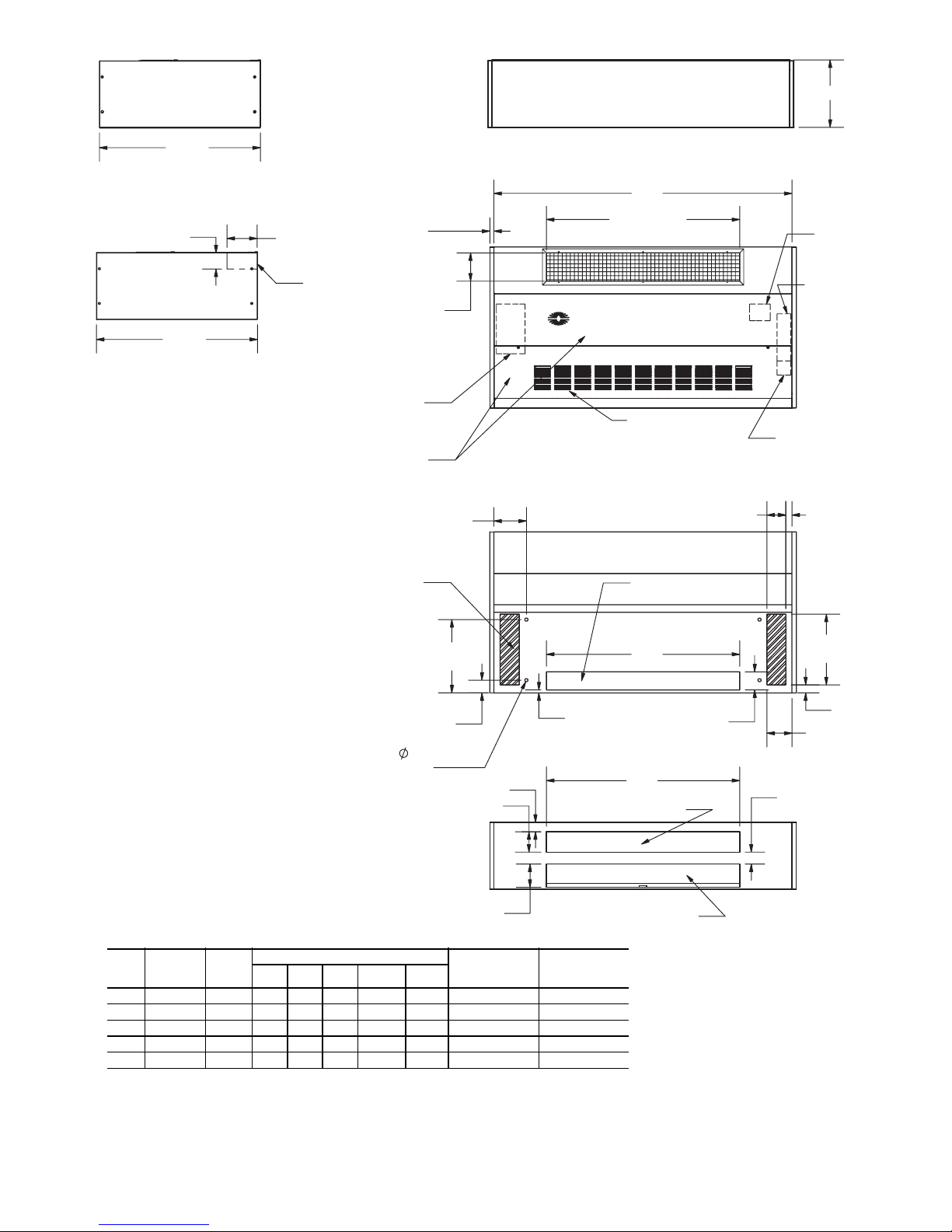
16.63
40.00
LEFT SIDE VIEW
(SIZES 075 TO 150)
4.00
44.00
LEFT SIDE VIEW
(SIZE 200)
7.50
(UNIT SHOWN
END PANELS)
PIPE
TUNNEL
CCN
CONTROLLER
(OPTIONAL)
BOTTOM SERVICE
PANELS
(SEE NOTE 3)
REMOVABLE PANEL
(EACH EN
1.00
WITH 1.00"
W5 (OPENING)
(TYP-SEE
NOTE 2)
D)
8.00
FRONT VIEW
W1
(SEE NOTE 2)
W3
(OPENING)
RETURN AIR
LOUVERED PANEL
(OPTIONAL)
BOTTOM VIEW
TOP OUTSIDE AIR
OPENING (OPTIONAL)
4.75
(TYP)
MOTOR
ELECTRICAL
BOX
NON-FUSED
SCONNECT
DI
SWITCH
1.00 (TYP)
W4
(TYP)
3.67
(TYP)
(MOUNTING HOLES-
TYP-4 PLACES)
LEGEND
.75
2.27
5.00
5.75
CCN — Carrier Comfort Network®
UNIT
AIRFLOW
40UH
(cfm)
075 750 40 62 36 36 18.67 7.00 530 515
100 1000 40 74 48 48 18.67 7.00 640 620
125 1250 40 86 60 60 18.67 7.00 790 770
150 1500 40 98 72 72 18.67 7.00 880 860
200 2000 44 98 72 72 26.92 10.00 1050 1030
DEPTH
(in.)
DIMENSIONS (in.) APPROXIMATE
W1 W2 W3 W4 W5
SHIPPING
WEIGHT (lb)
APPROXIMATE
W2
1.25
TOP VIEW
W2
REAR OUTSIDE AIR
OPENING (OPTIONAL)
REAR RETURN AIR
OPENING (OPTIONAL)
REAR VIEW
NOTES:
INSTALLED
WEIGHT (lb)
17.50
(TYP)
2.50
4.50
3.00
1. All dimensions are in inches.
2. Dimension does not include end panels.
3. Two bottom panels provided for service
access.
4. Motor and electrical power input box on
right side of unit. Box includes fan
speed switch, On/Off switch and nonfused disconnect switch.
5. Connection hand is determined by facing discharge of unit.
(TYP)
6.75 (TYP)
Fig. 5 — 40UH Dimensions — Down Discharge Plenum
7
Page 8
Make Piping Connections — Access to piping is
available through the access panels at the front, top, or end of
the vertical unit (horizontal access from bottom or side). Route
piping through the pipe tunnel or the unit’s back panel or floor
panel. Metal blank-off panels must be trimmed to complete
piping installation. All piping connections must be performed
by qualified personnel in accordance with local and national
codes.
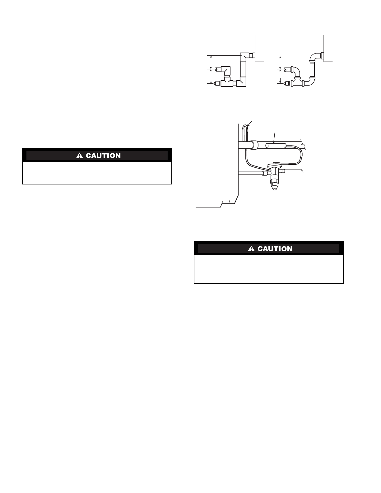
DRAIN CONNECTIONS — Condensate drain connections
are located on each end of the drain pan near the bottom of the
unit. Condensate drain line must be
galvanized pipe, PVC or similar plastic pipe. Install drain line
in accordance with all applicable codes. Insulate the drain
line to prevent sweating. See Fig. 6 for typical drain trap
construction.
Units with cooling coils require traps to prevent air from
entering the condensate fitting and preventing proper drainage.
Drain must flow downhill from the unit a minimum of
per ft. Drain must be free and clear at all times.
3
/4in. copper tubing,
1
/8in.
3/4"
PVC OR COPPER
3" MIN
2" MIN
3" MIN
2" MIN
3/4"
GALVANIZED PIPE
Fig. 6 — Typical Condensate Drain Trap
Construction
EQUALIZER
SENSING BULB (CLAMPED TO
SUCTION LINE AND INSULATED)
SUCTION LINE
Insulate drain lines to prevent condensate. Care must be
taken to avoid interference with control panel on left side
drain.
WATER SUPPLY/RETURN CONNECTIONS — Install piping in accordance with all applicable codes. All piping must be
supported separately from coils.
Water supply must be connected so that entering water is on
leaving-air side of coil. See the connection labels on the unit to
locate the inlet. Coils must be adequately vented to prevent air
binding. Be sure valves are in proper operating position and are
easily accessible for adjustment.
If coil and valve package connections will be made with a
solder joint, care should be taken to ensure that components in
the valve package are not subjected to high temperatures which
may damage seals or other materials. Many 2-position electric
control valves are provided with a manual operating lever. This
lever should be in the OPEN position during all soldering
operations.
If coil connection is made with a union, the coil side of the
union must be prevented from turning (it must be backed up)
during tightening. Do not overtighten! Overtightening will dis-
tort (egg shape) the union seal surface and destroy the union.
NOTE: A freezestat is factory-installed when a hot water/steam
coil is installed.
STEAM CONNECTIONS — On units with steam heating
coils, the maximum steam pressure applied to the unit should
never exceed 10 psig (operating pressure 6 psig).
DIRECT EXPANSION REFRIGERANT PIPING — Use the
condensing unit manufacturer’s recommended line sizes and
requirements. Perform leak test using nitrogen. Evacuate and
charge per recommended heating, ventilation, and air conditioning (HVAC) procedures and all applicable codes. Insulate
suction line after leak test up to the coil section end plate for
correct operation and to eliminate sweating. Use refrigerantgrade copper lines only. The unit is NOT to be applied as a
heat pump.
See Fig. 7 for refrigerant piping connections with recommended locations for the thermostatic expansion valve (TXV)
and sensing bulb.
HYDRONIC COIL PIPING — When all joints are complete,
perform hydrostatic test for leaks. Vent all coils at this time.
Check interior unit piping for signs of leakage from shipping
damage or mishandling. If leaks are found, notify a Carrier
representative before initiating any repairs. Release trapped air
from system (refer to Make Final Preparations section).
LIQUID LINE
NOTE: Follow TXV manufacturer’s instructions.
Fig. 7 — Typical TXV (Thermostatic Expansion
Valve) Installation
All water coils must be protected from freezing after initial
filling with water. Even if system is drained, unit coils may
still have enough remaining water to cause damage when
exposed to temperatures below freezing.
Following the hydrostatic test, insulate all piping up to the
coil section end plate to prevent sweating.
To ensure compliance with building codes, restore the structure’s original fire resistance rating by sealing all holes with
material carrying the same fire rating as the structure.
Make Electrical Connections — Refer to unit serial
plate for required supply voltage, fan and heater amperage and
required circuit ampacities. Refer to unit wiring diagram for
unit and field wiring. See Tables 2-4 for electrical data.
All input power wiring connections are accessed through
the electrical panel on front right-hand side of the unit. Use the
openings that are for the piping connections. See the dimensional drawings Fig. 1-5 for electrical box connections.
The fan motor should never be controlled by any wiring or
device other than the factory-supplied switch or thermostat/
switch combination unless prior factory authorization is obtained. Fan motor may be temporarily wired for use during
construction only with prior factory approval and only in strict
accordance with the instructions issued at that time.
All electrical connections should be made by qualified personnel and be in accordance with governing codes and ordinances. Any modification of unit wiring without factory authorization
will invalidate all factory warranties and nullify any agency listings. See Fig. 8A and 8B for typical wiring connections for basic
unit without CCN (Carrier Comfort Network®) controls.
Actuators (Field-Supplied) — Field-supplied actuators
must be mounted on1/2in. diameter damper shafts.
8
Page 9
Table 2 — Electric Heater Data for Units with PSC Motor
UNIT HP
NOMINAL
V/Ph/Hz
NUMBER
OF
ELEMENTS
3 17.2 90 21.5 25 3.2
208/1/60
4 22.2 97 27.8 30 4.2
5 27.3 104 34.1 35 5.3
6 32.3 110 40.4 45 6.3
3 19.5 97 24.4 25 4.2
240/1/60
4 25.3 106 31.7 35 5.6
5 31.2 115 39.0 40 7.0
6 37.0 124 46.3 50 8.4
3 16.8 97 21.0 25 4.2
4 21.8 106 27.3 30 5.6
5 26.9 115 33.6 35 7.0
6 31.9 124 39.9 40 8.4
3 10.8 90 13.5 15 3.2
4 15.8 97 19.8 20 4.2
5 19.5 104 24.4 25 5.3
40UV050
(at 500 Cfm)
277/1/60
1
/
5
208/3/60
6 19.5 110 24.4 25 6.3
3 12.1 97 15.1 20 4.2
240/3/60
4 17.9 106 22.4 25 5.6
5 22.2 115 27.8 30 7.0
6 22.2 124 27.8 30 8.4
3 6.0 97 7.5 15 4.2
460/3/60
4 8.9 106 11.1 15 5.6
5 11.0 115 13.8 15 7.0
6 11.0 124 13.8 15 8.4
LEGEND NOTES:
DX — Direct Expansion
FLA — Full Load Amps
LAT — Leaving-Air Temperature at 70 F Entering-Air
Temperature
MCA — Unit Minimum Circuit Ampacity
MOCP — Maximum Overcurrent Protection (Maximum Fuse Size
or Circuit Breaker Amps)
PSC — Permanent Split Capacitor
FLA
LAT
(F)
MCA MOCP
TOTAL
CAPACITY
(kW)
1. LAT (Leaving Air Temperature)(F) is measured at nominal cfm.
2. Water and DX coils used on electric heat units have left-hand
coil connections.
3. Electric heat is available in the reheat position only and connections are on the right side.
4. Face and bypass units are available with 3 heating elements
only.
9
Page 10
Table 2 — Electric Heater Data for Units with PSC Motor (cont)
UNIT HP
NOMINAL
V/Ph/Hz
NUMBER
OF
ELEMENTS
3 23.7 89 29.6 30 4.5
208/1/60
4 30.9 96 38.6 40 6.0
5 38.1 102 47.6 50 7.5
6 45.3 108 56.7 60 9.0
3 27.0 96 33.8 35 6.0
240/1/60
4 35.3 104 44.2 45 8.0
5 43.7 113 54.6 60 10.0
6 52.0 121 65.0 70 12.0
3 23.3 96 29.1 30 6.0
4 30.5 104 38.1 40 8.0
5 37.7 113 47.1 50 10.0
6 44.9 121 56.2 60 12.0
3 14.5 89 18.2 20 4.5
4 21.7 96 27.2 30 6.0
5 27.0 102 33.8 35 7.5
40UV,UH075
(at 750 Cfm)
277/1/60
1
/
5
208/3/60
6 27.0 108 33.8 35 9.0
3 16.5 96 20.6 25 6.0
240/3/60
4 24.8 104 31.0 35 8.0
5 30.9 113 38.6 40 10.0
6 30.9 121 38.6 40 12.0
3 8.2 96 10.2 15 6.0
460/3/60
4 12.3 104 15.4 20 8.0
5 15.4 113 19.2 20 10.0
6 15.4 121 19.2 20 12.0
LEGEND NOTES:
DX — Direct Expansion
FLA — Full Load Amps
LAT — Leaving-Air Temperature at 70 F Entering-Air
Temperature
MCA — Unit Minimum Circuit Ampacity
MOCP — Maximum Overcurrent Protection (Maximum Fuse Size
or Circuit Breaker Amps)
PSC — Permanent Split Capacitor
FLA
LAT
(F)
MCA MOCP
TOTAL
CAPACITY
(kW)
1. LAT (Leaving Air Temperature)(F) is measured at nominal cfm.
2. Water and DX coils used on electric heat units have left-hand
coil connections.
3. Electric heat is available in the reheat position only and connections are on the right side.
4. Face and bypass units are available with 3 heating elements
only.
10
Page 11
Table 2 — Electric Heater Data for Units with PSC Motor (cont)
UNIT HP
NOMINAL
V/Ph/Hz
NUMBER
OF
ELEMENTS
3 30.9 89 38.6 40 6.0
208/1/60
4 40.5 95 50.7 60 8.0
5 50.2 102 62.7 70 10.0
6 59.8 108 74.7 80 11.9
3 35.3 96 44.2 45 8.0
240/1/60
4 46.5 104 58.1 60 10.7
5 57.6 112 72.0 80 13.3
6 68.7 121 85.8 90 16.0
3 30.5 96 38.1 40 8.0
4 40.1 104 50.1 60 10.7
5 49.7 112 62.2 70 13.3
6 59.4 121 74.2 80 16.0
3 18.7 89 23.4 25 6.0
4 28.3 95 35.4 40 8.0
5 35.4 102 44.3 45 10.0
40UV,UH100
(at 1000 Cfm)
277/1/60
1
/
5
208/3/60
6 35.4 108 44.3 45 11.9
3 21.3 96 26.6 30 8.0
240/3/60
4 32.4 104 40.5 45 10.7
5 40.5 112 50.7 60 13.3
6 40.5 121 50.7 60 16.0
3 10.6 96 13.2 15 8.0
460/3/60
4 16.1 104 20.1 25 10.7
5 20.2 112 25.2 30 13.3
6 20.2 121 25.2 30 16.0
LEGEND NOTES:
DX — Direct Expansion
FLA — Full Load Amps
LAT — Leaving-Air Temperature at 70 F Entering-Air
Temperature
MCA — Unit Minimum Circuit Ampacity
MOCP — Maximum Overcurrent Protection (Maximum Fuse Size
or Circuit Breaker Amps)
PSC — Permanent Split Capacitor
FLA
LAT
(F)
MCA MOCP
TOTAL
CAPACITY
(kW)
1. LAT (Leaving Air Temperature)(F) is measured at nominal cfm.
2. Water and DX coils used on electric heat units have left-hand
coil connections.
3. Electric heat is available in the reheat position only and connections are on the right side.
4. Face and bypass units are available with 3 heating elements
only.
11
Page 12
Table 2 — Electric Heater Data for Units with PSC Motor (cont)
UNIT HP
NOMINAL
V/Ph/Hz
NUMBER
OF
ELEMENTS
3 38.1 89 47.6 50 7.5
208/1/60
4 50.1 96 62.7 70 10.0
5 62.2 102 77.7 80 12.5
6 74.2 108 92.8 100 15.0
3 43.7 96 54.6 60 10.0
240/1/60
4 57.6 104 71.9 80 13.3
5 71.4 113 89.3 90 16.7
6* 85.3 121 106.7 110 20.0
3 37.7 96 47.1 50 10.0
4 49.7 104 62.2 70 13.3
5 61.8 113 77.2 80 16.7
6 73.8 121 92.2 100 20.0
3 22.9 89 28.6 30 7.5
4 34.9 96 43.6 45 10.0
5 43.7 102 54.7 60 12.5
40UV,UH125
(at 1250 Cfm)
277/1/60
1
/
5
208/3/60
6 43.7 108 54.7 60 15.0
3 26.1 96 32.6 35 10.0
240/3/60
4 40.0 104 50.0 50 13.3
5 50.2 113 62.7 70 16.7
6 50.2 121 62.7 70 20.0
3 13.0 96 16.2 20 10.0
460/3/60
4 19.9 104 24.9 25 13.3
5 25.0 113 31.3 35 16.7
6 25.0 121 31.3 35 20.0
LEGEND
DX — Direct Expansion
FLA — Full Load Amps
LAT — Leaving-Air Temperature at 70 F Entering-Air
Temperature
MCA — Unit Minimum Circuit Ampacity
MOCP — Maximum Overcurrent Protection (Maximum Fuse Size
or Circuit Breaker Amps)
PSC — Permanent Split Capacitor
*Left-hand coil connections only.
FLA
LAT
(F)
NOTES:
1. LAT (Leaving Air Temperature)(F) is measured at nominal cfm.
MCA MOCP
TOTAL
CAPACITY
(kW)
2. Water and DX coils used on electric heat units have left-hand
coil connections.
3. Electric heat is available in the reheat position only and connections are on the right side.
4. Face and bypass units are available with 3 heating elements
only.
12
Page 13
Table 2 — Electric Heater Data for Units with PSC Motor (cont)
UNIT HP
NOMINAL
V/Ph/Hz
NUMBER
OF
ELEMENTS
3 45.3 89 56.7 60 9.0
208/1/60
4 59.8 96 74.7 80 12.0
5 74.2 102 92.8 100 15.0
6* 88.7 108 110.8 125 18.0
3 52.0 96 65.0 70 12.0
240/1/60
4 68.7 104 85.8 90 16.0
5* 85.3 113 106.7 110 20.0
6 —————
3 44.9 96 56.2 60 12.0
4 59.4 104 74.2 80 16.0
5 73.8 113 92.3 100 20.0
6 —————
3 27.0 89 33.8 35 9.0
4 41.5 96 51.9 60 12.0
5 52.1 102 65.1 70 15.0
40UV,UH150
(at 1500 Cfm)
277/1/60
1
/
5
208/3/60
6 52.1 108 65.1 70 18.0
3 30.9 96 38.6 40 12.0
240/3/60
4 47.6 104 59.5 60 16.0
5 59.8 113 74.8 80 20.0
6 59.8 121 74.8 80 24.0
3 15.4 96 19.2 20 12.0
460/3/60
4 23.7 104 29.6 30 16.0
5 29.8 113 37.3 40 20.0
6 29.8 121 37.3 40 24.0
LEGEND
DX — Direct Expansion
FLA — Full Load Amps
LAT — Leaving-Air Temperature at 70 F Entering-Air
Temperature
MCA — Unit Minimum Circuit Ampacity
MOCP — Maximum Overcurrent Protection (Maximum Fuse Size
or Circuit Breaker Amps)
PSC — Permanent Split Capacitor
*Left-hand coil connections only.
FLA
LAT
(F)
NOTES:
1. LAT (Leaving Air Temperature)(F) is measured at nominal cfm.
MCA MOCP
TOTAL
CAPACITY
(kW)
2. Water and DX coils used on electric heat units have left-hand
coil connections.
3. Electric heat is available in the reheat position only and connections are on the right side.
4. Face and bypass units are available with 3 heating elements
only.
13
Page 14
Table 3 — Electric Heater Data for Units with ECM
UNIT HP
NOMINAL
V/Ph/Hz
NUMBER
OF
ELEMENTS
3 16.5 90 20.6 25 3.2
208/1/60
4 21.5 97 26.9 30 4.2
5 26.6 104 33.2 35 5.3
6 31.6 110 39.5 40 6.3
3 18.8 97 23.5 25 4.2
240/1/60
4 24.6 106 30.8 35 5.6
5 30.5 115 38.1 40 7.0
6 36.3 124 45.4 50 8.4
3 16.3 97 20.3 25 4.2
4 21.3 106 26.6 30 5.6
5 26.4 115 33.0 35 7.0
6 31.4 124 39.3 40 8.4
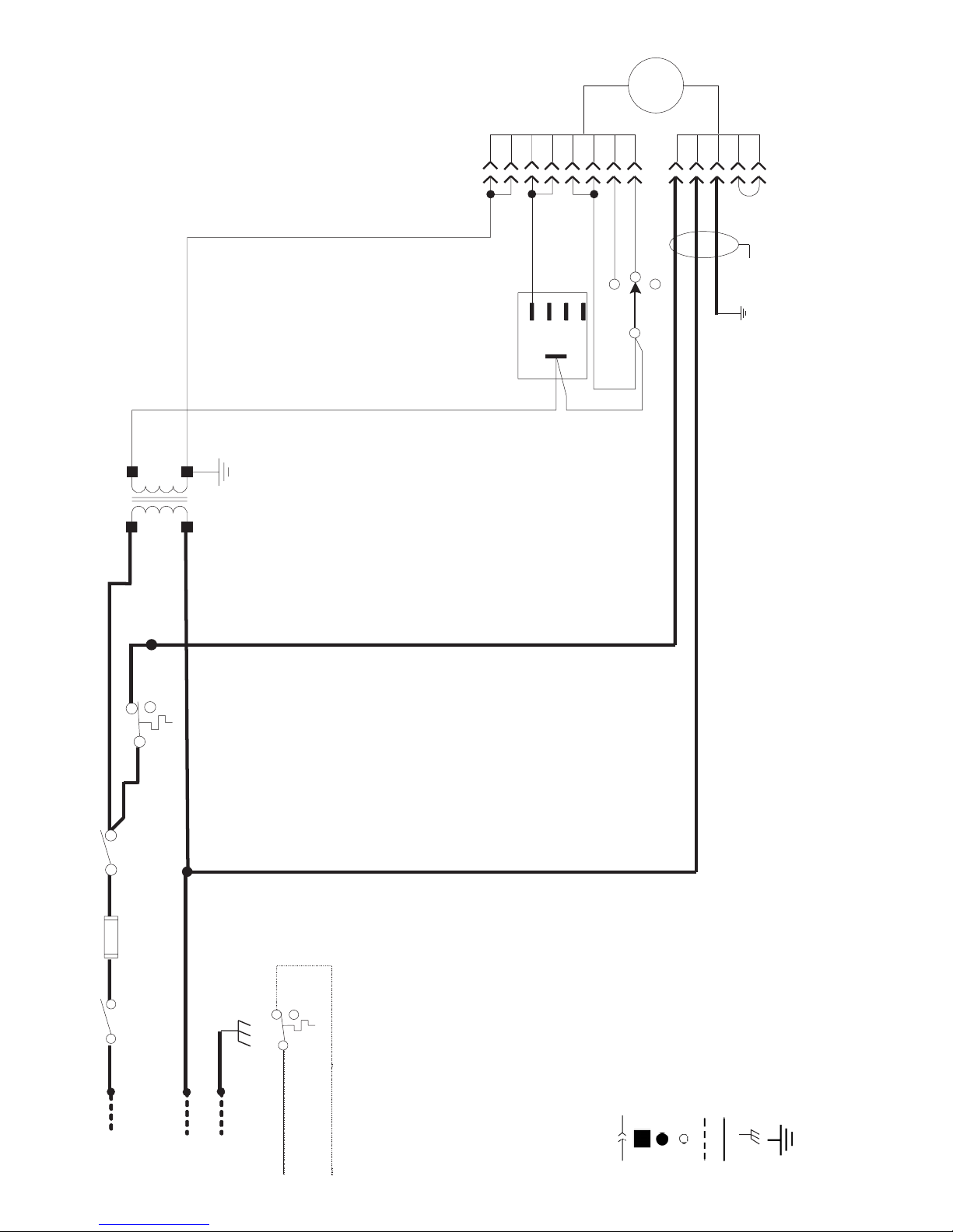
3 10.1 90 12.6 15 3.2
4 15.1 97 18.9 20 4.2
5 18.8 104 23.5 25 5.3
40UV050
(at 500 Cfm)
277/1/60
1
/
3
208/3/60
6 18.8 110 23.5 25 6.3
3 11.4 97 14.3 15 4.2
240/3/60
4 17.2 106 21.6 25 5.6
5 21.5 115 26.9 30 7.0
6 21.5 124 26.9 30 8.4
3 5.4 97 6.8 15 4.2
460/3/60
4 8.3 106 10.4 15 5.6
5 10.5 115 13.1 15 7.0
6 10.5 124 13.1 15 8.4
LEGEND NOTES:
DX — Direct Expansion
FLA — Full Load Amps
LAT — Leaving-Air Temperature at 70 F Entering-Air
Temperature
MCA — Unit Minimum Circuit Ampacity
MOCP — Maximum Overcurrent Protection (Maximum Fuse Size
or Circuit Breaker Amps)
PSC — Permanent Split Capacitor
FLA
LAT
(F)
MCA MOCP
TOTAL
CAPACITY
(kW)
1. LAT (Leaving Air Temperature)(F) is measured at nominal cfm.
2. Water and DX coils used on electric heat units have left-hand
coil connections.
3. Electric heat is available in the reheat position only and connections are on the right side.
4. Face and bypass units are available with 3 heating elements
only.
14
Page 15
Table 3 — Electric Heater Data for Units with ECM (cont)
UNIT HP
NOMINAL
V/Ph/Hz
NUMBER
OF
ELEMENTS
3 24.0 89 30.0 30 4.5
208/1/60
4 31.2 96 39.0 40 6.0
5 38.4 102 48.0 50 7.5
6 45.6 108 57.0 60 9.0
3 27.3 96 34.1 35 6.0
240/1/60
4 35.6 104 44.5 45 8.0
5 44.0 113 55.0 60 10.0
6 52.3 121 65.4 70 12.0
3 23.7 96 29.6 30 6.0
4 30.9 104 38.6 40 8.0
5 38.1 113 47.6 50 10.0
6 45.3 121 56.7 60 12.0
3 14.8 89 18.5 20 4.5
4 22.0 96 27.6 30 6.0
5 27.3 102 34.2 35 7.5
40UV,UH075
(at 750 Cfm)
277/1/60
1
/
3
208/3/60
6 27.3 108 34.2 35 9.0
3 16.8 96 20.9 25 6.0
240/3/60
4 25.1 104 31.4 35 8.0
5 31.2 113 39.0 40 10.0
6 31.2 121 39.0 40 12.0
3 8.2 96 10.2 15 6.0
460/3/60
4 12.3 104 15.4 20 8.0
5 15.4 113 19.2 20 10.0
6 15.4 121 19.2 20 12.0
LEGEND NOTES:
DX — Direct Expansion
FLA — Full Load Amps
LAT — Leaving-Air Temperature at 70 F Entering-Air
Temperature
MCA — Unit Minimum Circuit Ampacity
MOCP — Maximum Overcurrent Protection (Maximum Fuse Size
or Circuit Breaker Amps)
PSC — Permanent Split Capacitor
FLA
LAT
(F)
MCA MOCP
TOTAL
CAPACITY
(kW)
1. LAT (Leaving Air Temperature)(F) is measured at nominal cfm.
2. Water and DX coils used on electric heat units have left-hand
coil connections.
3. Electric heat is available in the reheat position only and connections are on the right side.
4. Face and bypass units are available with 3 heating elements
only.
15
Page 16
Table 3 — Electric Heater Data for Units with ECM (cont)
UNIT HP
NOMINAL
V/Ph/Hz
NUMBER
OF
ELEMENTS
3 31.5 89 39.4 40 6.0
208/1/60
4 41.1 95 51.4 60 8.0
5 50.8 102 63.4 70 10.0
6 60.4 108 75.5 80 11.9
3 35.9 96 44.9 45 8.0
240/1/60
4 47.1 104 58.8 60 10.7
5 58.2 112 72.7 80 13.3
6 69.3 121 86.6 90 16.0
3 31.2 96 39.0 40 8.0
4 40.8 104 51.0 60 10.7
5 50.4 112 63.1 70 13.3
6 60.1 121 75.1 80 16.0
3 19.3 89 24.1 25 6.0
4 28.9 95 36.2 40 8.0
5 36.0 102 45.0 50 10.0
40UV,UH100
(at 1000 Cfm)
277/1/60
1
/
3
208/3/60
6 36.0 108 45.0 50 11.9
3 21.9 96 27.3 30 8.0
240/3/60
4 33.0 104 41.2 45 10.7
5 41.1 112 51.4 60 13.3
6 41.1 121 51.4 60 16.0
3 10.6 96 13.3 15 8.0
460/3/60
4 16.2 104 20.2 25 10.7
5 20.3 112 25.3 30 13.3
6 20.3 121 25.3 30 16.0
LEGEND NOTES:
DX — Direct Expansion
FLA — Full Load Amps
LAT — Leaving-Air Temperature at 70 F Entering-Air
Temperature
MCA — Unit Minimum Circuit Ampacity
MOCP — Maximum Overcurrent Protection (Maximum Fuse Size
or Circuit Breaker Amps)
PSC — Permanent Split Capacitor
FLA
LAT
(F)
MCA MOCP
TOTAL
CAPACITY
(kW)
1. LAT (Leaving Air Temperature)(F) is measured at nominal cfm.
2. Water and DX coils used on electric heat units have left-hand
coil connections.
3. Electric heat is available in the reheat position only and connections are on the right side.
4. Face and bypass units are available with 3 heating elements
only.
16
Page 17
Table 3 — Electric Heater Data for Units with ECM (cont)
UNIT HP
NOMINAL
V/Ph/Hz
NUMBER
OF
ELEMENTS
3 39.4 89 49.3 50 7.5
208/1/60
4 51.5 96 64.3 70 10.0
5 63.5 102 79.4 80 12.5
6 75.5 108 94.4 100 15.0
3 45.0 96 56.2 60 10.0
240/1/60
4 58.9 104 73.6 80 13.3
5 72.7 113 90.9 100 16.7
6* 86.6 121 108.3 110 20.0
3 39.0 96 48.7 50 10.0
4 51.0 104 63.8 70 13.3
5 63.1 113 78.8 80 16.7
6 75.1 121 93.9 100 20.0
3 24.2 89 30.2 35 7.5
4 36.2 96 45.3 50 10.0
5 45.0 102 56.3 60 12.5
40UV,UH125
(at 1250 Cfm)
277/1/60
1
/
2
208/3/60
6 45.0 108 56.3 60 15.0
3 27.4 96 34.2 35 10.0
240/3/60
4 41.3 104 51.6 60 13.3
5 51.5 113 64.3 70 16.7
6 51.5 121 64.3 70 20.0
3 13.2 96 16.5 20 10.0
460/3/60
4 20.2 104 25.2 30 13.3
5 25.3 113 31.6 35 16.7
6 25.3 121 31.6 35 20.0
LEGEND
DX — Direct Expansion
FLA — Full Load Amps
LAT — Leaving-Air Temperature at 70 F Entering-Air
Temperature
MCA — Unit Minimum Circuit Ampacity
MOCP — Maximum Overcurrent Protection (Maximum Fuse Size
or Circuit Breaker Amps)
PSC — Permanent Split Capacitor
*Left hand coil connections only.
FLA
LAT
(F)
NOTES:
1. LAT (Leaving Air Temperature)(F) is measured at nominal cfm.
MCA MOCP
TOTAL
CAPACITY
(kW)
2. Water and DX coils used on electric heat units have left-hand
coil connections.
3. Electric heat is available in the reheat position only and connections are on the right side.
4. Face and bypass units are available with 3 heating elements
only.
17
Page 18
Table 3 — Electric Heater Data for Units with ECM (cont)
UNIT HP
NOMINAL
V/Ph/Hz
NUMBER
OF
ELEMENTS
3 46.7 89 58.3 60 9.0
208/1/60
4 61.1 96 76.4 80 12.0
5 75.6 102 94.4 100 15.0
6* 90.0 108 112.5 125 18.0
3 53.3 96 66.6 70 12.0
240/1/60
4 70.0 104 87.5 90 16.0
5* 86.6 113 108.3 110 20.0
6 —————
3 46.2 96 57.8 60 12.0
4 60.7 104 75.8 80 16.0
5 75.1 113 93.9 100 20.0
6 —————
3 28.3 89 35.4 40 9.0
4 42.8 96 53.5 60 12.0
5 53.4 102 66.7 70 15.0
40UV,UH150
(at 1500 Cfm)
277/1/60
1
/
2
208/3/60
6 53.4 108 66.7 70 18.0
3 32.2 96 40.3 45 12.0
240/3/60
4 48.9 104 61.1 70 16.0
5 61.1 113 76.4 80 20.0
6 61.1 121 76.4 80 24.0
3 15.6 96 19.5 20 12.0
460/3/60
4 24.0 104 30.0 30 16.0
5 30.1 113 37.6 40 20.0
6 30.1 121 37.6 40 24.0
LEGEND
DX — Direct Expansion
FLA — Full Load Amps
LAT — Leaving-Air Temperature at 70 F Entering-Air
Temperature
MCA — Unit Minimum Circuit Ampacity
MOCP — Maximum Overcurrent Protection (Maximum Fuse Size
or Circuit Breaker Amps)
PSC — Permanent Split Capacitor
*Left hand coil connections only.
FLA
LAT
(F)
NOTES:
1. LAT (Leaving Air Temperature)(F) is measured at nominal cfm.
MCA MOCP
TOTAL
CAPACITY
(kW)
2. Water and DX coils used on electric heat units have left-hand
coil connections.
3. Electric heat is available in the reheat position only and connections are on the right side.
4. Face and bypass units are available with 3 heating elements
only.
18
Page 19
Table 3 — Electric Heater Data for Units with ECM (cont)
UNIT HP
NOMINAL
V/Ph/Hz
NUMBER
OF
ELEMENTS
3 50.1 84 62.7 70 9.0
208/1/60
4 64.6 89 80.7 90 12.0
5 79.0 94 98.8 100 15.0
6* 93.5 99 116.8 125 18.0
3 56.8 89 71.0 80 12.0
240/1/60
4 73.5 96 91.8 100 16.0
5* 90.1 102 112.7 125 20.0
6 —————
3 48.8 89 61.0 70 12.0
4 63.3 96 79.1 80 16.0
5 77.7 102 97.1 100 20.0
6 —————
3 31.8 84 39.8 40 9.0
4 46.3 89 57.9 60 12.0
5 56.9 94 71.1 80 15.0
40UH200
(at 2000 Cfm)
277/1/60
3
/
4
208/3/60
6 56.9 99 71.1 80 18.0
3 35.7 89 44.6 45 12.0
240/3/60
4 52.4 96 65.5 70 16.0
5 64.6 102 80.8 90 20.0
6 64.6 108 80.8 90 24.0
3 16.9 89 21.1 25 12.0
460/3/60
4 25.2 96 31.5 35 16.0
5 31.3 102 39.1 40 20.0
6 31.3 108 39.1 40 24.0
LEGEND
DX — Direct Expansion
FLA — Full Load Amps
LAT — Leaving-Air Temperature at 70 F Entering-Air
Temperature
MCA — Unit Minimum Circuit Ampacity
MOCP — Maximum Overcurrent Protection (Maximum Fuse Size
or Circuit Breaker Amps)
PSC — Permanent Split Capacitor
*Left hand coil connections only.
FLA
LAT
(F)
NOTES:
1. LAT (Leaving Air Temperature)(F) is measured at nominal cfm.
MCA MOCP
TOTAL
CAPACITY
(kW)
2. Water and DX coils used on electric heat units have left-hand
coil connections.
3. Electric heat is available in the reheat position only and connections are on the right side.
4. Face and bypass units are available with 3 heating elements
only.
19
Page 20
Table 4 — Motor Data
PSC MOTORS
UNIT 40UV,UH SIZE MOTOR Hp VOLTAGE FLA MCA MOP (Amps)
1
050*
075
100
125
150
/
5
1
/
5
1
/
5
1
/
5
1
/
5
UNIT 40UV,UH SIZE MOTOR Hp VOLTAGE FLA MCA MOP (Amps)
050*
075
100
125
150
200†
1
/
3
1
/
3
1
/
3
1
/
2
1
/
2
3
/
4
LEGEND
ECM — Electronically Commutated Motor
FLA — Full Load Amps
MCA — Minimum Circuit Amps
MOP — Maximum Overload Protection
PSC — Permanent Split Capacitor
*Available in vertical configuration only.
†Available in horizontal configuration only.
115 3.7 4.6 8.3 15
208/230 2.0 2.5 4.5 15
265 1.6 2.0 3.6 15
115 3.7 4.6 8.3 15
208/230 2.0 2.5 4.5 15
265 1.6 2.0 3.6 15
115 3.7 4.6 8.3 15
208/230 2.0 2.5 4.5 15
265 1.6 2.0 3.6 15
115 3.7 4.6 8.3 15
208/230 2.0 2.5 4.5 15
265 1.6 2.0 3.6 15
115 3.7 4.6 8.3 15
208/230 2.0 2.5 4.5 15
265 1.6 2.0 3.6 15
ECM
115 1.4 1.8 3.1 15
208/230 1.3 1.6 2.9 15
265 1.1 1.4 2.6 15
115 3.7 4.6 8.3 15
208/230 2.3 2.9 5.1 15
265 2.0 2.5 4.5 15
115 4.0 5.0 9.1 15
208/230 2.6 3.2 5.8 15
265 2.3 2.9 5.1 15
115 4.7 5.9 10.6 15
208/230 3.3 4.1 7.4 15
265 2.9 3.6 6.6 15
115 4.7 5.9 10.6 15
208/230 3.3 4.1 7.4 15
265 2.9 3.6 6.6 15
115 9.6 12.0 21.6 20
208/230 6.8 8.5 15.3 15
265 5.5 6.9 12.4 15
MAXFUSESIZE
(Amps)
MAXFUSESIZE
(Amps)
20
Page 21
ECM
16 PIN
ON MOTOR
RECE PTACLE
1
3
5
11
BRN
YEL/EC5
2
9
12
14
ORN/EC2
RED/EC12
MAX
5
BLK
BLU/EC9
HIGH
LOW
SEE NOTE 3
SW2
MAX
MED
LOW
HIGH
SPEED BOARD
24Vac
RED/EC12
RED/502
RED/503
5 PIN
ON MOTOR
RECE PTACLE
4
3
2
1
GRN
WHT
CABLE
3 WIRE
POWER
RED/502
TRAN1
BLK/109
BLK/104
(SEE NOTE 2)
LLT
BLK/103
BLK/109
SW1
BRN/EC1
BLK
GRN
WHT/111WHT/111
NOTE 2
pliance with national and local electrical codes.
are for field use with increased ESP.
Fig. 8A — Unit Ventilator Wiring Without CCN Controls (115 vac)
WHT
1. Make electrical installation in accordance with job diagram, and in com-
2. Low limit thermostat (LLT) is installed on all units with water coils.
NOTES:
3. Wire YEL/EC5 factory connected to LOW. Positions MED, HIGH, MAX
24 VAC
120VAC
1
3
2
BLK/102
FU1
BLK/101
DISC1
BLK/100
WHT/110
WHT/110
3
1
LLR
2
GRN
USE COPPER SUPPLY WIRES
L1
GND
FIELD CONNECTED TO
REMOTE CONDENSER.
LLR INSTALLED ONLY ON
N
115 V
LEGEND
Harness Connection
Connection Point Splice
Splice Terminal Connection
Component Tie Point
Optional Wiring
Factory Wiring
Chassis Ground
Earth Ground
DISC — Disconnect Switch
DX — Direct Expansion
ECM — Electronically Commutated Motor
ESP — External Static Pressure
FU — Fuse
GND — Ground
LLR — DX Low Limit Switch
LLT — Water Coil Low Limit Thermostat
SW — Switch
UNITS WITH DX COILS.
TRAN — Transformer
21
Page 22
16 PIN
ECM
ON MOTOR
RECE PTACLE
1
3
5
11
BRN
YEL/EC5
SEE NOTE 3
MED
LOW
HIGH
SPEED BOARD
24Vac
RED/502RED/503
2
9
12
14
ORN/EC2
RED/EC12
MAX
SW2
MAX
5
BLK
BLU/EC9
HIGH
LOW
RED/EC12
5 PIN
ON MOTOR
RECE PTACLE
4
3
2
1
GRN
WHT
CABLE
3 WIRE
POWER
RED/502
TRAN1
240 V
BLK/109
BLK/104
(SEE NOTE 2)
LLT
BLK/109
BLK/103
SW1
BLK/102
3
208 V
2
BRN/EC1
24VAC
SEE NOTE 4
1
COM
BLK/108
BLK
NOTE 2
BLK/108
BLK/107
GRN
WHT
local electrical codes.
1. Make electrical installation in accordance with job diagram, and in compliance with national and
NOTES:
listed on the unit nameplate.
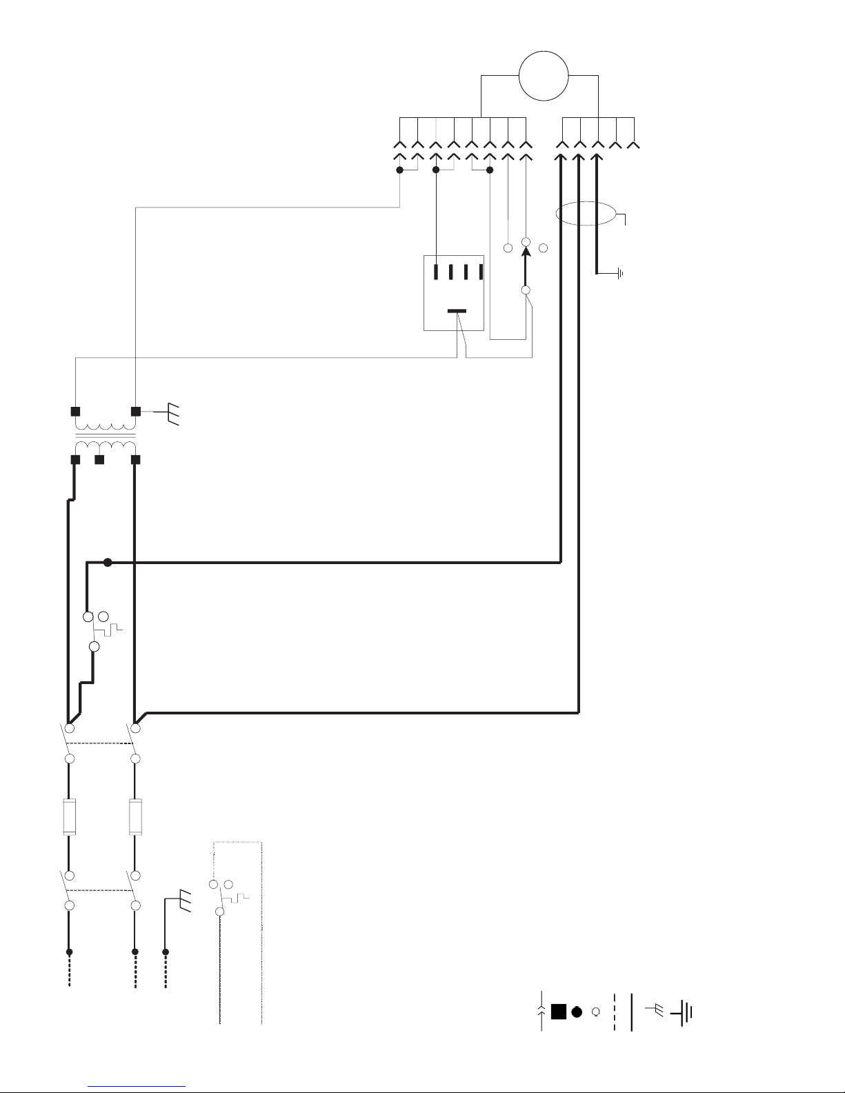
Fig. 8B — Unit Ventilator Wiring Without CCN Controls (208/230 vac)
2. Low limit thermostat (LLT) is installed on all units with water coils.
3. Wire YEL/EC5 factory connected to LOW. Positions MED, HIGH, MAX are for field use with ESP.
4. Transformers shown wired for 240v. However, transformers are factory-wired to match the voltage
208/230V
USE COPPER SUPPLY WIRES
FU2
BLK/106
3
1
LLR
2
GRN
BLK/105
L2
GND
FIELD CONNECTED TO
REMOTE CONDENSER.
LLR INSTALLED ONLY ON
UNITS WITH DX COILS.
FU1
BLK/101
DISC1
BLK/100
L1
22
LEGEND
Harness Connection
Connection Point Splice
Splice Terminal Connection
Component Tie Point
Optional Wiring
Factory Wiring
Chassis Ground
Earth Ground
DISC — Disconnect Switch
DX — Direct Expansion
ECM — Electronically Commutated Motor
ESP — External Static Pressure
FU — Fuse
GND — Ground
LLR — DX Low Limit Switch
LLT — Water Coil Low Limit Thermostat
SW — Switch
TRAN — Transformer
Page 23
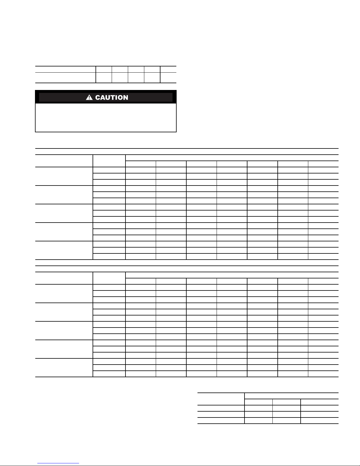
Make Duct Connections — If applicable, install all
ductwork to and from unit in accordance with all applicable
codes. Duct construction must allow unit to operate within duct
external static pressure limits as shown on job submittals and in
Tables 5 and 6. Duct opening should be the same size as the
unit. For 40UH units ducted to multiple openings, allow adequate straight duct, as shown below, immediately after the unit.
40UH 075 100 125 150 200
Minimum Straight Duct
Required (Length in ft)
Units designed to operate with ductwork may be damaged
if operated without intended ductwork attached.
Ensure that units ducted to multiple openings have sufficient
straight duct immediately after the unit.
FACTORY SETTINGS — CHILLED WATER COIL APPLICATIONS
Unit Speed
40UV050
40UV,UH075
40UV,UH100
40UV,UH125
40UV,UH150
45 52 58 63 75
Table 5 — Unit Ventilator Airflow — PSC Motor*
1-row 2-row 3-row 4-row 5-row 6-row 7-row
Max 522 510 497 485 490 489 457
High 503 490 476 464 473 476 444
Low 458 449 440 425 452 455 430
Max 806 778 750 747 766 732 697
High 682 664 645 629 621 596 570
Low 569 554 539 527 533 514 495
Max 1064 1033 1001 1013 973 980 967
High 662 659 655 642 763 740 717
Low 530 519 507 503 498 501 504
Max 1295 1285 1215 1218 1239 1250 1175
High 899 930 876 865 852 846 846
Low 568 616 597 570 568 558 573
Max 1542 1480 1500 1484 1468 1482 1374
High 1071 1068 1065 1034 1033 1031 1013
Low 812 801 790 881 848 842 799
Units provided with outside air must utilize the low-
temperature safety switch to prevent coil freeze-up.
Insulate all ductwork as required. Use flexible connections
to minimize duct-to-unit alignment problems and noise transmission where specified.
Install ductwork, grilles, and plenums so that they do not restrict access to filter.
Cut openings for supply and return air grilles, thermostats,
and switch plates where specified on job drawings. Be careful
not to cut wires, piping, or structural supports. Use a steel thermostat shield ring to protect drywall from thermostat wiring
where applicable.
Prevent dust and debris from settling in unit. If wall finish or
color is to be applied by spraying, cover all openings to
prevent spray from entering unit.
Approximate Air Delivery (Cfm)
FACTORY SETTINGS — ELECTRIC HEAT/DX COIL APPLICATIONS
Unit Speed
40UV050
40UV,UH075
40UV,UH100
40UV,UH125
40UV,UH150
LEGEND
CX — Chilled Water Applications
DX — Direct Expansion
HW — Hot Water
*Standard on sizes 050-150.
Max 522 510 497 485 490 489 457
High 503 490 476 464 452 455 430
Low 458 449 440 425 410 414 406
Max 806 778 750 747 766 732 697
High 682 664 645 629 621 596 570
Low 569 554 539 527 533 514 495
Max 1064 1033 1001 1013 973 980 967
High 794 788 782 773 857 834 810
Low 662 659 655 642 628 620 611
Max 1295 1285 1215 1218 1239 1250 1175
High 1055 1040 1024 995 1099 1091 1052
Low 738 767 732 719 987 986 964
Max 1542 1480 1500 1484 1468 1482 1374
High 1285 1257 1229 1248 1246 1239 1199
Low 934 928 922 901 1033 1031 1013
1-row 2-row 3-row 4-row 5-row 6-row 7-row
Approximate Air Delivery (Cfm)
NOTE: Use the table below to determine the heating and cooling coil
combinations available with PSC Motor operation.
COOLING COIL
5RowsCW 1 or 2 rows N/A 3 elements
4RowsCW 3 rows 1 or 2 rows 4 elements
3RowsCWorDX† 4rows 1or2rows 5or6elements
†DX cooling applications are only available in 3-row cooling
configuration.
HW Steam Electric
HEATING COIL
23
Page 24
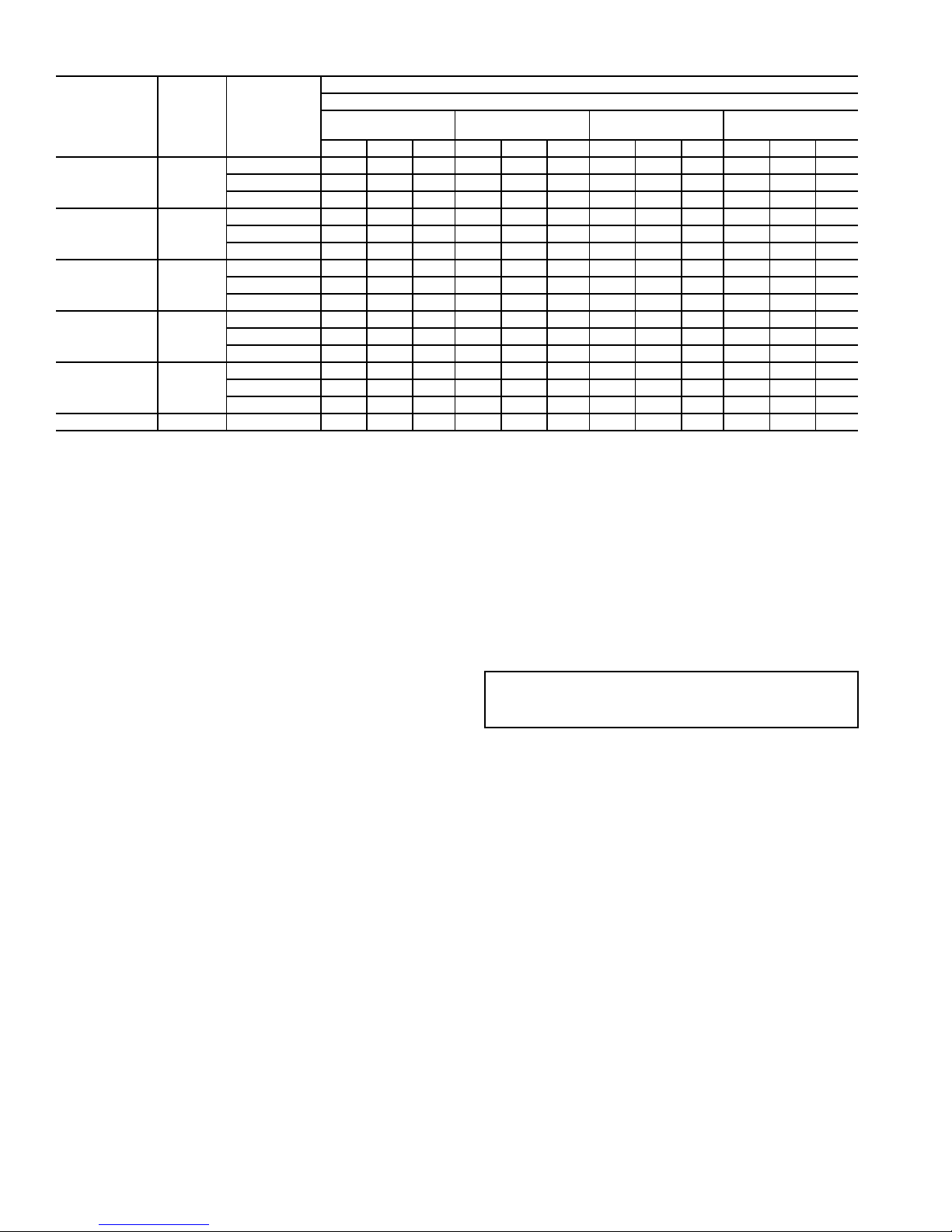
Table 6 — Unit Ventilator Airflow — ECM Airflow
UNIT SIZE
40UV050
40UV,UH075
40UV,UH100
40UV,UH125
40UV,UH150
40UH200
3-4EH/DX— Direct Expansion Coil Applications with 3 to
5-6EH — 5 to 6 Elements of Electric Heat
CW — Chilled Water Applications
ESP — External Static Pressure
MOTOR
HP
1
/
3
1
/
3
1
/
3
1
/
2
1
/
2
3
/
4
LEGEND NOTES:
4 Elements of Electric Heat
COIL TYPE
CW 499 336 248 — — — — — — — — —
3-4EH/DX 499 419 336 — — — — — — — — —
5-6EH 491 380 324 — — — — — — — — —
CW 747 484 346 753 548 432 752 530 437 751 541 386
3-4EH/DX 747 644 498 753 609 472 752 612 470 751 618 498
5-6EH 755 645 583 746 598 539 755 585 554 765 610 542
CW 997 703 505 987 693 543 1012 663 483 994 692 480
3-4EH/DX 997 853 615 987 850 639 1012 823 626 994 819 618
5-6EH 1016 819 719 1002 851 709 1024 798 787 1024 820 734
CW 1266 880 657 1239 905 609 1235 898 676 1231 898 627
3-4EH/DX 1266 1023 769 1239 1055 758 1235 1037 765 1231 1010 778
5-6EH 1259 1049 897 1239 995 888 1226 995 888 1253 994 919
CW 1503 1033 775 1479 1046 712 1494 1020 770 1486 1075 737
3-4EH/DX 1503 1246 956 1479 1216 965 1494 1209 927 1486 1222 917
5-6EH 1517 1222 1068 1490 1206 1087 1498 1159 1120 1503 1188 1074
ALL 2014 1384 1023 1981 1386 971 1965 1385 997 1814 1354 993
Low Position
(0.0 in. wg)
Max High Low Max High Low Max High Low Max High Low
APPROXIMATE AIR DELIVERY (Cfm)
ESP Speed Board Position
Med Position
(0.10 in. wg)
1. Factory default is Low Position.
2. Med, High, and Max positions are field settings.
High Position
(0.25 in. wg)
Max Position
(0.45 in. wg)
Make Final Preparations
1. Turn power off (lock out and tag electrical disconnect).
2. Install thermostats and perform any other final wiring as
applicable.
3. Clean dirt, dust, and other construction debris from unit
interior. Be sure to check fan wheel and housing.
4. Rotate fan wheel by hand to be sure it is free and does not
rub on housing.
5. Be sure drain line is clear and is properly and securely
positioned. Pour water into drain to check operation.
6. Vent all air from unit coil and related piping. If air vent is
manual, release air from system by turning air vent screw
1
/2turns counterclockwise with screwdriver. When
1
steady stream of water begins to escape, close valve. If air
vent is automatic, trapped air will be vented automatically. Vent releases air slowly, usually dripping water into
drain pan in the process.
Make sure all service valves are open and that motorized
control valves, if supplied, are set for automatic operation.
7. Check all control valves in the system for proper operation in accordance with valve manufacturer’s instructions.
8. For units with factory-installed balancing valves, adjust
as follows:
a. Butterfly valves — Turn valve gate by inserting
screwdriverintoslotinvalvetopandrotatingupto
90 degrees. Valve is fully open when slot is parallel
with valve body. When slot is perpendicular to
body, flow through valve is at minimum. Valve
does not seal against flow.
b. Ball valves with lever handles — Valve gate action
is similar to butterfly valves above except that
when handle is perpendicular to valve body, there
is no flow through valve. Ball valves may be used
as shutoff valves.
9. Install filter in frame at front of coil. If field-supplied
filters are used, be sure size is correct. See Table 1 for
filter data.
10. Ensure all panels and filters are installed before checking
fan operation. Turn on unit power. Check fan and motor
operation.
.
IMPORTANT: Do not start up or operate unit without
filter and panels installed. Be sure filter and unit interior
are clean.
START-UP
Start-up procedures vary depending on time of year (summer or winter) and building characteristics (new building/old
building, occupied/unoccupied, etc.).
Start-up in the Cooling mode requires proper care to avoid
condensation problems. Condensation forms on surfaces that
are colder than the dew point of the surrounding air. If a unit is
started and is piped with low-temperature chilled water in a
hot, humid atmosphere, condensation will form on many parts
of the unit. In order to avoid excessive condensation, higher
temperature water should initially be used (approximately 65 to
70 F). Also, the building should be as completely closed as
possible. Close the unit’s outside-air dampers. Bathroom and
kitchen exhaust fans should be off.
As the building temperature drops, the chilled water temperature can be gradually reduced until it reaches 50 F. At this
point the outside-air damper can be opened to take in minimum
outside air. When the chilled water temperature is reduced to its
design point, the exhaust fans can be turned on.
24
Page 25
SERVICE
Lock out and tag all power supplies to equipment and controls prior to servicing unit. Follow all safety codes. Failure
to do so could result in personal injury.
Preventing Excessive Condensation on Unit —
Excessive condensation can be caused by running chilled water
through a unit with the unit fan off. If fan cycling is used, a water
flow control valve should be installed to shut off the water when
the fan stops.
Other methods of control which avoid condensation prob-
lems are as follows:
1. If condensation is forming on the unit, verify the chilled
water valve is closing off tightly. Dirt or debris may prevent the valve from closing completely.
2. Continuous fan operation with motorized chilled water
valve controlled by a thermostat.
3. Continuous fan operation with thermostat control to
switchfanfromhightolowspeed(insteadofoff).
Check Drain — Checkdrainpan,drainline,andtrapat
start of each cooling season. A standard type pipe cleaner for
3
/4-in. ID pipe can be used to be sure pipe is clear of obstruction
so that condensate is carried away. Check the drain line at filter
cleaning time during the cooling season. Be sure that debris has
not fallen into unit through supply air grille.
Fan Motor Bearings — Standard motors are perma-
nent split capacitor, which are equipped with permanently
sealed and lubricated bearings. No lubrication is required
unless special motors have been supplied or unusual operating
conditions exist.
Fan Shaft Ball Bearing — The mid and inboard bear-
ings are permanently sealed and lubricated. No additional
maintenance is required. The end bearings must be lubricated at
the start of each cooling and heating season. Add 5 to 10 drops
of SAE 20 or 30 non-detergent based oil to the bearing.
Clean Fan Wheel — For access to fan assembly, remove
discharge grille (if supplied). If unit is connected to ductwork,
remove front (40UV) or bottom (40UH) panel, separate fan
shaft from motor at bushing, remove motor, and slide fan
assembly from track. Use a stiff brush or vacuum to remove
dirt and debris from scroll. Wipe all fan surfaces with a damp
cloth. Reassemble as necessary.
Clean or Replace Air Filters — At the start of each
cooling season and after each month of operation (more or less
depending on operating conditions), replace throwaway filter
or clean permanent filter.
THROWAWAY FILTER — Replace filter with a good quality
filter of the correct size. Do not attempt to clean and reuse
disposable filters. See Table 1 for filter sizes.
PERMANENT FILTER (FIBER TYPE)
1. Tap on solid surface to dislodge heavy particles.
2. Wash in hot water. If needed, use mild solution of commercial solvent such as sal soda or trisodium phosphate.
3. Set filter on end so that water drains out through slots in
frame. Allow filter to dry thoroughly.
4. Recharge filter with recharging oil. Three ounces is sufficient for a medium size filter. Oil may be applied by insect
spray gun. For easier spraying, the oil can be warmed.
If the filter is dipped in the recharging oil, remove it
immediately and allow to drain through slots in frame.
5. Replace filter in unit.
If another type of filter is used, follow the filter manufactur-
er’s instructions.
ECM Motor Removal and Reinstallation
(Fig.9)—
commutated motor (ECM) to drive the indoor fan.
The ECM is a factory programmed motor that is standard
with factory-supplied controls (CCN) and units without
factory-supplied controls that are used in high-static applications or high-capacity coils.
The ECM is programmed with an algorithm that maintains
a constant torque, as the static pressure on the system varies.
For example, as the filter pressure drop increases due to dirt,
the fan will increase speed (rpm) to maintain the cfm.
The ECM is identified by the two electrical receptacles
located on the housing. See Fig. 8A, 8B and 9.
The first receptacle is a 5-row in-line connector that feeds
the motor line voltage. This may be either 115 volts or
230 volts. Units that are wired for 230 volts have a jumper between terminals 1 and 2 on this plug (see wiring diagram).
The second receptacle on the motor is a 16-pin connector
and is used for speed switching. This is a low voltage (24-volt)
connection. There is a jumper wire between terminals 1 and 3.
This is a 24-volt ground. Voltage is present at all times when
the motor is energized.
NOTE: A time delay exists between the time the motor speed
is switched and the motor’s reaction. This is designed into the
electronics and does not indicate motor problems.
When replacing the motor, note the following:
• Check the part number of the old motor against that of
the replacement. There is a tag indicating the eight-digit
part number and begins with UVE. This is the program
number used for this motor.
• The motor must be installed per the instructions below.
It is important to maintain the dimension between the
fan compartment bulkhead and the coupling.
IMPORTANT: If a replacement cooling shroud has been
supplied, it should be installed and the old one
discarded. The motor shroud directs cooling air across
the motor to provide proper cooling. Never run the
motor without the cooling shroud in place. Ensure
the shroud inlet ring does not touch the motor; a gap of
1
/16in. to1/8in. is acceptable.
Ensure the unit is completely assembled when checking the
fan speed. Replace all panels, including the filters, before
checking the fan for operation. When the internal pressure
drops at a normal condition, the loading on the motor will
be such that the fan can come up to selected speed.
Failure to ensure unit is completely assembled may
result in reduced life of unit and/or personal injury.
To remove and re-install the motors, proceed as follows;
refer Fig. 9:
1. Remove the wire plugs from the motor.
2. Remove the 2 screws holding the motor shroud to the
bulkhead.
3. Slide the shroud off the motor to the right.
4. Loosen the 3 setscrews on the shaft coupling between the
motor shaft and the fan shaft.
Carrier unit ventilators utilize an electronically
25
Page 26
MOTOR SHAFT
COUPLING
FAN
SHAFT
+
.125 .032
–
0.500 0.063
INSTALL MOTOR
AND COOLING
SHROUD
ELECTRICAL
CONNECTIONS
FACING UNIT
FRONT.
CENTER SHROUD
OPENING OVER
MOTOR ELECTRICAL
CONNECTIONS.
+
–
+
1.000 0.063
–
SHAFTED END FACE
INSULATION FACE
MOTOR (ECM)
COUPLING INSIDE FACE
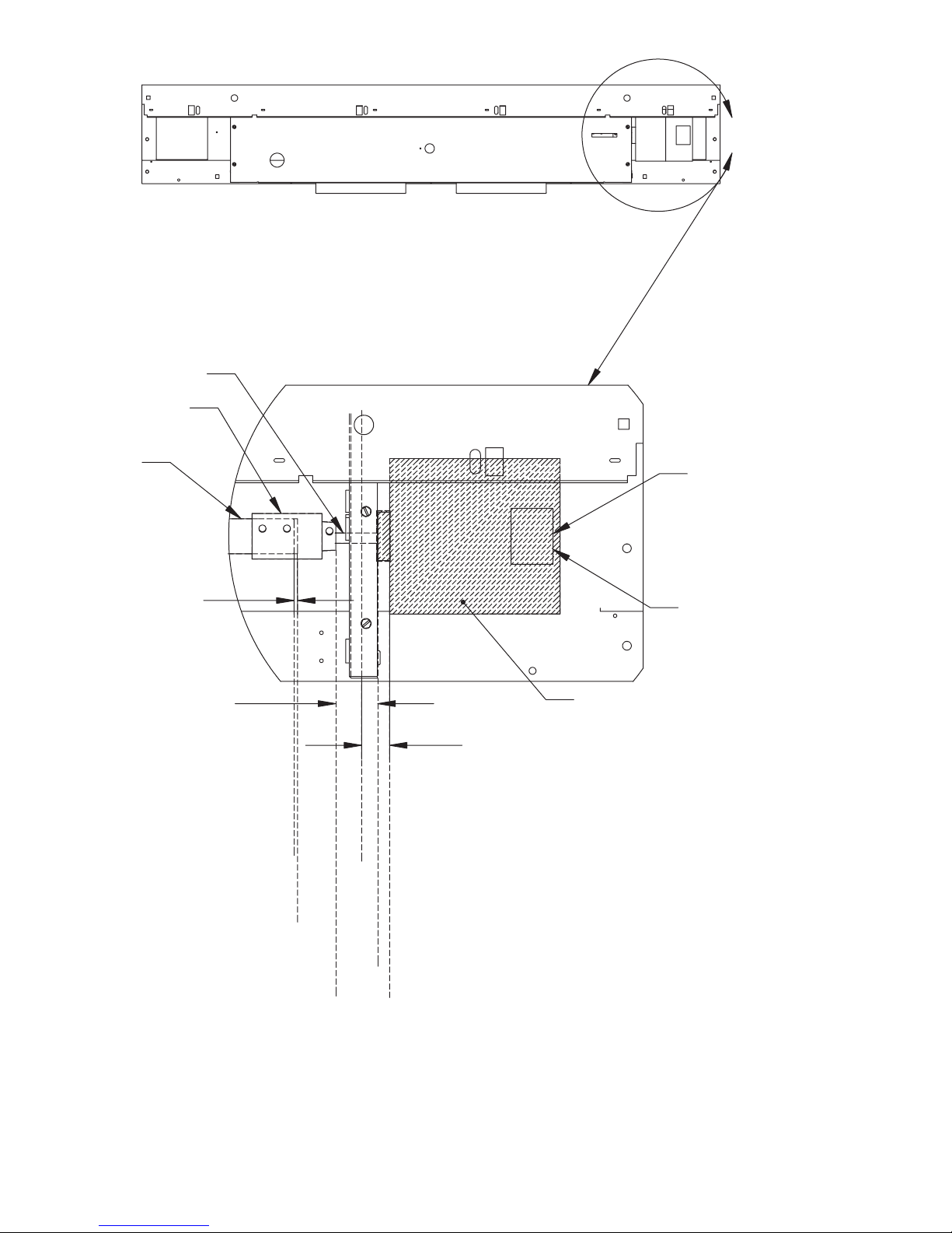
Fig. 9 — 40UV,UH Ventilator Blower Section Assembly — ECM Motor Detail
COUPLING FACE
MOTOR BEARING FACE
MOTOR FACE
26
NOTES:
1. All dimensions shown in inches.
2. Not all components shown for clarity.
3. Motor shroud not shown for clarity. Install prior
to operation.
4. Refer to Fig. 15 for cooling shroud installation.
Page 27
5. Loosen the motor ‘belly band’ and slide motor out of the
‘belly band’ to the right. It is unnecessary to remove the
motor mounting bracket from the bulkhead. Loosen only
the ‘belly band’ securing the motor in the mount.
6. Reinstall the motor in the ‘belly band.’
7. Ensure the blower wheels are centered within the fan
housings (between the inlet rings) before securing the
motor shaft coupling.
The motor electronics will fail prematurely if no air is able
to circulate over the motor.
8. Ensure the motor housing is at least 1 in. from the
bulkhead so that air will be able to circulate over the
motor.
9. For vertical type units, position the motor so that the
motor wire plugs are front facing on a horizontal plane.
For horizontal type units with ceiling mounts, position the
motor so that the motor wire plugs are front facing on a
vertical plane.
10. Secure the 3 setscrews on the shaft coupling when the
motor is properly positioned and the blower wheels are
centered within their housing.
11. Re-secure the motor ‘belly band’ around the motor.
12. Reinstall the motor shroud. It is important that the motor
shroud be installed prior to operation of the motor. Ensure
the venturi is installed on the motor shroud.
13. Re-secure the two screws holding the motor shroud to the
bulkhead.
14. Reinstall the motor wire plugs.
Blower Assembly Section Removal and Reinstallation (Fig. 10)
Lock out and tag all power supplies to equipment and controls prior to servicing unit. Follow all safety codes. Failure
to do so could result in personal injury.
Be careful with all components during installation, especially the bearing and plastic blower wheels. Any extreme
force applied to these components can cause unintended
damage and void the unit warranty.
To remove blower assembly:
1. Turn off power to the unit.
IMPORTANT: Tag each right front panel (40UV) or
middle bottom panel (40UH) for each unit. Panels have
electrical information specific to each unit.
2. Remove all front (40UV) or bottom (40UH) panels. Remove end panels.
3. Remove top panel with
vanes and screens to the side (40UV). Remove ductwork
if required and remove top (40UV) or front (40UH) discharge plenum.
4. Remove
1
/4in. head screws along length of unit that se-
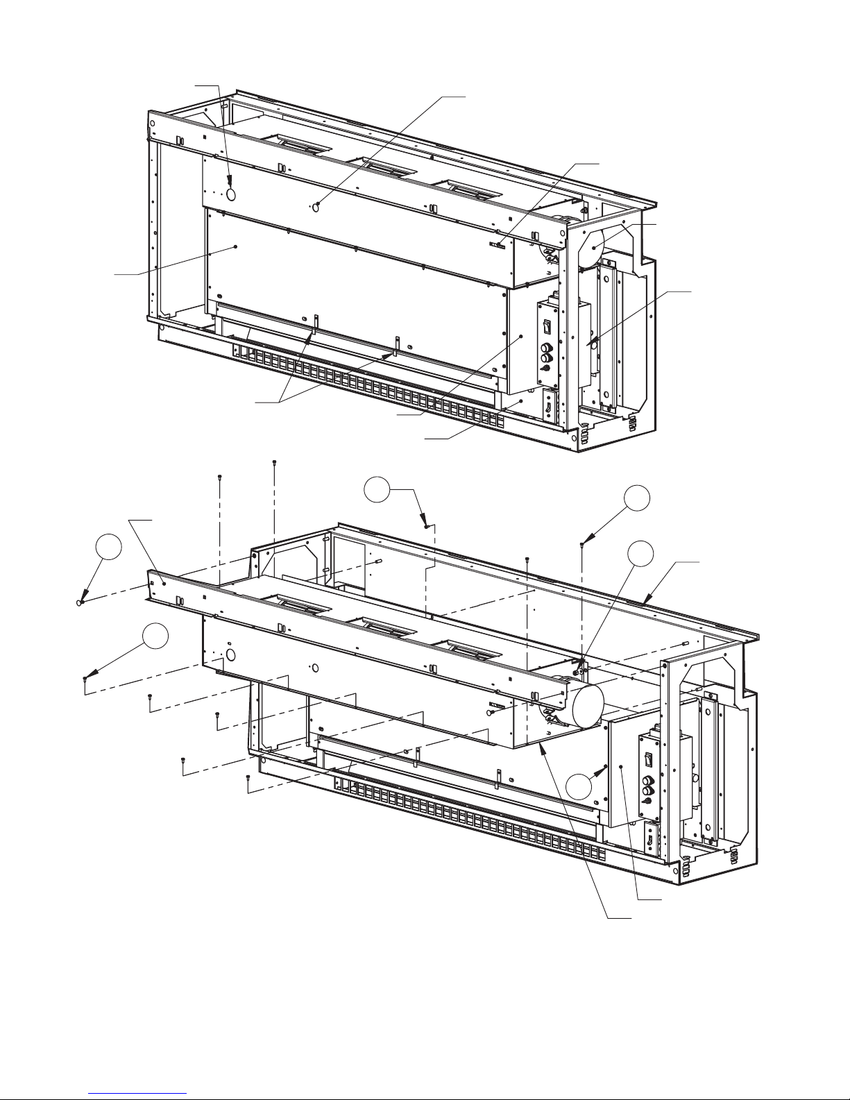
cure coil baffle to blower section. See Item 5 in Fig. 10.
5
/16in. nut driver and set optional
5. Remove four
1
/4in. head screws that connect the blower
section sides to the coil section sides. See Item 2 in
Fig. 10.
6. Remove the
1
/4in. head screw from the center of the
blower deck that attaches the blower deck to the pipe
chase. See Item 1 in Fig. 10.
1
7. Remove six
/4in. head screws attaching coil baffle to
coil section. See Item 4 in Fig. 10.
8. Remove the harness connector(s) from the motor.
1
9. Remove the
/4in. head screw from the green ground
wire that connects the motor to frame if unit has a PSC
motor. ECM motors are grounded through the harness.
10. Remove the two carriage bolts retaining the front brace to
the frame sides. See Item 6 in Fig. 10.
11. Remove the four nuts retaining the blower section to the
back (40UV) or top (40UH) frame. See Item 3 in Fig. 10.
5
12. Remove the two
/16in. nuts retaining the inboard bearing
bracket to the pipe chase (40UV,UH150 units only). See
Item6inFig.11.
13. Remove blower section from frame.
To reinstall blower assembly to frame of unit:
1. Reinstall blower section into frame assembly.
2. Tighten the four
5
/16in. nuts retaining blower section to
frame. See Item 3 in Fig. 10.
5
3. Tighten the two
/16in. nuts retaining the inboard bearing
bracket to the pipe chase (40UV,UH150 units only). See
Item6inFig.11.
4. Reinstall two carriage bolts that attach the front brace to
the frame sides. See Item 6 in Fig. 10.
5. Rotate the fan shaft by hand to ensure that fans are
unrestricted and can rotate freely. Check for any fan
obstructions.
6. Re-attach green ground wire that connects the motor to
the frame with ¼ in. head screw if unit has a PSC motor.
ECM motors are grounded through the harness.
7. Connect harness connector(s) to motor.
8. Reinstall the coil baffle using six
1
/4in. head screws that
attach the coil baffle to the coil section. See Item 4 in
Fig. 10.
1
9. Reinstall the
/4in. head screw at center of blower deck
attaching blower deck to pipe chase. See Item 1 in
Fig. 10.
1
10. Reinstall the four
/4in. head screws holding the blower
section sides to the coil section sides. See Item 2 in
Fig. 10.
1
11. Reinstall
/4in. head screws along length of the unit,
securing coil baffle to the blower section. See Item 5 in
Fig. 10.
12. Reinstall optional vanes and screens and install top panel
(40UV). Reinstall top (40UV) or front (40UH) discharge
plenum and ductwork, if required.
13. Reinstall front (40UV) or bottom (40UH) panels. Reinstall end panels. Ensure that tag on each right front
panel (40UV) or middle bottom panel (40UH) matches unit tag.
14. Restore power to unit.
IMPORTANT: Disassembly order is not as important as
reassembly. The assembly order of the bearing bracket
installation is critical to having a well balanced and
sound blower deck.
27
Page 28
COIL BAFFLE
RETURN AIR
TEMPERATURE
SENSOR (OPTIONAL)
OPENING
FILTER DOOR RETAINER
CLIPS (SEE NOTE 3)
COIL SECTION
DAMPER SECTION
DISCHARGE AIR
TEMPERATURE
SENSOR (OPTIONAL)
OPENING
MOTOR & COUPLING
SETCREW ACCESS
MOTOR
MOTOR
ELECTRICAL
BOX
FRONT
BRACE
6
5
NOTES:
1. Unit shown in vertical orientation. Drawing applies
to horizontal and vertical units.
2. Not all components shown for clarity.
3. 40UV,UH125-200 units only.
1
2
3
PIPE
CHASE
4
COIL SECTION
BLOWER SECTION
Fig. 10 — 40UV,UH Ventilator Blower Section
28
Page 29
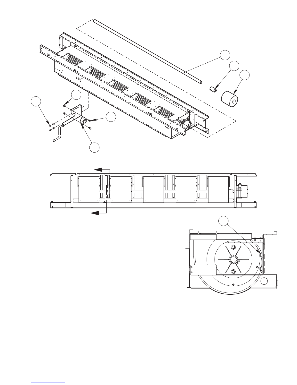
SEE NOTE 4
1
2
3
7
6
4
5
SEE DETAIL A
SEE DETAIL A
NOTES:
1. Not all components shown for clarity.
2. This drawing applies to 1500 cfm units only.
3. Remove shaft, motor, and coupling prior to
bearing removal.
4. Refer to Fig. 16 and 17 for motor-coupling and
coupling-shaft clearances.
Fig. 11 — 40UV,UH Ventilator Inboard Bearing (40UV,UH150 Only)
BOTTOM VIEW
6
DETAIL A
29
Page 30
Coil Assembly Removal and Reinstallation
(Fig. 12)
Lock out and tag all power supplies to equipment and controls prior to servicing unit. Follow all safety codes. Failure
to do so could result in personal injury.
Turn off all power supplies to equipment and controls. Failure to do so may cause personal injury or damage to the
unit.
To remove coil assembly:
1. Turn off power to the unit.
IMPORTANT: Tag each right front panel (40UV) or
middle bottom panel (40UH) for each unit. Panels have
electrical information specific to each unit.
2. Remove all front (40UV) or bottom (40UH) panels. Remove end panels.
1
3. Remove
cure coil baffle to blower section. See Item 2 in Fig. 12.
4. Remove four
section sides to the coil section sides. See Item 1 in
Fig. 12.
5. Remove
tuator to damper shaft OR locking quadrant assembly to
damper shaft. Remove OA actuator or locking quadrant
assembly.
6. Tag low-limit thermostat wiring and terminals. Disconnect low-limit thermostat wiring (right end
compartment).
/4in. head screws along length of unit that se-
1
/4in. head screws that connect the blower
1
/4in. head screws attaching outside air (OA) ac-
7. Drain water and/or recover refrigerant in accordance
with all applicable codes. Disconnect piping from coil
connections.
8. Tag optional electric heat element wire terminations for
later reconnection. Disconnect element wires from electric heat control box (remove coil baffle for access).
5
9. Remove the four
/16in. nuts retaining the coil section to
the frame.
10. Remove coil section from frame.
To reinstall coil assembly:
1. Replace coil section into frames assembly.
5
2. Tighten the four
/16in. nuts retaining coil section to
frame.
3. Reconnect electric heat wiring in electric heat control
box.
4. Reconnect wiring to low limit thermostat.
1
5. Replace the four
/4in. head screws holding the blower
deck to coil section (two on each side).
6. Replace coil baffle using
1
/4in. head screws. See Item 2
in Fig. 12.
7. Reinstall outside air actuator or locking quadrant handle
1
/4in. head screws.
using
8. Reconnect piping to coils. If water coil, purge air from
coils and perform hydrostatic test to check for leaks. If
DX coil, perform leak test using nitrogen, and evacuate
and charge per recommended HVAC procedures and all
applicable codes.
9. Replace coil section side insulation.
10. Replace front (40UV) or bottom (40UH) panels. Replace
end panels. Ensure that tag on each right front panel
(40UV) or middle bottom panel (40UH) matches unit
tag.
11. Restore power to unit.
30
Page 31
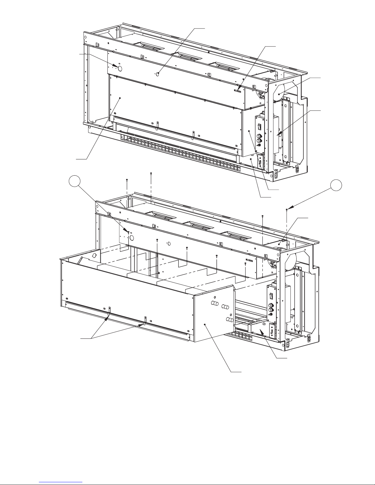
RETURN AIR
TEMPERATURE
SENSOR OPENING
FRONT
COIL
BAFFLE
DISCHARGE AIR
TEMPERATURE SENSOR
OPENING
MOTOR & COUPLING
SETSCREW ACCESS
MOTOR
MOTOR
ELECTRICAL
BOX
2
FILTER DOOR
RETAINER CLIPS
(SEE NOTE 3)
NOTES:
1. Unit shown in vertical orientation. Drawing
applies to horizontal and vertical units.
2. Not all components shown for clarity.
3. 40UV,UH125-150, 40UH200 units only.
COIL SECTION
DAMPER SECTION
COIL SECTION
DAMPER SECTION
1
BLOWER SECTION
Fig. 12 — 40UV,UH Ventilator Coil Section
31
Page 32
Ball Bearing Replacement (40UV,UH150;
40UH200 Units Only) —
units only, Fig. 14 for 40UV150 and 40UH150 units with PSC
motors, Fig. 15 for 40UV150 and 40UH150 units with ECM
motors.
Lock out and tag all power supplies to equipment and controls prior to servicing unit. Follow all safety codes. Failure
to do so could result in personal injury.
The assembly order of the bearing installation is critical. Be
careful with all components during removal and installation. Any excessive force applied to these components can
cause unintended damage and void unit warranty.
To replace ball bearing:
1. Turn off all power to unit.
IMPORTANT: Tag each right front panel (40UV) or
middle bottom panel (40UH) for each unit. Panels have
electrical information specific to each unit.
2. Remove front (40UV) or bottom (40UH) panels and right
(motor end) end panel.
3. Remove top panel and set optional vanes and screens to
the side (40UV). Remove ductwork if required and remove top (40UV) or front (40UH) discharge plenum. For
non-ducted 40UH horizontal units with front double deflection discharge grille, remove grille for access to wheel
setscrews. See Fig. 10.
4. Remove ¼ in. head screws along length of unit that secure coil baffle to blower section and remove front coil
baffle. See Item 5 in Fig. 10.
5. Loosen setscrews on all blower wheels (two per wheel).
See Fig. 11 and Fig. 13.
6. Loosen bearing setscrews.
7. Remove wiring harness connector(s) from motor.
8. If unit has ECM motor, remove motor shroud (sheet metal cover — Fig. 13, Item 6; Fig. 15, Item 4) by removing
5
/16in. hex nuts. Do not discard cooling shroud.
two
9. Loosen
Item 2; Fig. 15, Item 2), nut (Fig. 13, Item 3; Fig. 14,
Item 5; Fig. 15, Item 6), and bolt (Fig. 13, Item 4; Fig. 14,
Item 4; Fig. 15, Item 5), until motor housing (Fig. 13,
Item 5; Fig. 14, Item 3; Fig. 15, Item 3) moves freely.
10. Slide shaft-coupling-motor assembly (Fig. 11, Items 3, 2,
1; Fig. 13, Items 5, 2, 10) out of wheels and unit until
shaft clears inboard/center bearing assembly (30 in. max
clearance required from edge of frame end).
5
/16in. motor mount (Fig. 13, Item 7; Fig. 14,
Refer to Fig. 13 for 40UH200
11. Remove
1
/2in. bolts (Fig. 11, Item 4; Fig. 13, Item 9) and
hex nuts (Fig. 11, Item 7; Fig. 13, Item 1) securing bearing to bearing bracket. Remove bearing (Fig. 11, Item 5;
Fig. 13, Item 8).
12. Install new bearing (Fig. 11, Item 5; Fig. 13, Item 8).
Secure with
1
/2in. bolts (Fig. 11, Item 4; Fig. 13, Item 9)
and hex nuts (Fig. 11, Item 7; Fig. 13, Item 1).
13. Slide shaft-coupling-motor assembly (Fig. 11, Items 3, 2,
1; Fig. 13, Items 5, 2, 10) back into bearing and wheels.
Do not use excessive force. Damage to wheels may
occur.
14. Insert shaft-coupling-motor assembly into wheels until
motor clearance is as specified for motor type (PSC or
ECM). See Fig. 16 or Fig. 9.
15. Ensure that motor shaft is perpendicular to motor blower
endplate. Tighten
5
/16in. motor mount (Fig. 13, Item 7;
Fig. 14, Item 2; Fig. 15, Item 2), nut (Fig. 13, Item 3;
Fig. 14, Item 5; Fig. 15, Item 6), and bolt (Fig. 13, Item 4;
Fig. 14, Item 4; Fig. 15, Item 5), until motor (Fig. 13,
Item 5; Fig. 14, Item 3; Fig. 15, Item 3) is secure.
16. Install motor shroud (sheet metal cover — Fig. 13,
Item 6; Fig. 15, Item 4) using two
5
/16in. hex nuts if using
ECM motor. Align “window” with receptacles on motor.
Motor control module could overheat and fail if operated without cooling shroud.
17. Re-attach green ground wire that connects the motor to
the frame with
1
/4in. head screw if unit has a PSC motor.
ECM motors are grounded through the harness.
18. Re-attach wiring harness connector(s) to motor.
19. Center each wheel in its respective housing and tighten
wheel setscrews (two for each wheel).
20. Rotate the fan shaft by hand to ensure that fans are
unrestricted and can rotate freely. Check for any fan
obstructions.
21. Remove lockout and operate unit for approximately
60 seconds to let inboard/center bearing mount
self-adjust.
22. Lock out and tag all power supplies to equipment and
controls. Tighten the two bearing setscrews.
1
23. Reinstall the coil baffle using the six
/4in. head screws
that attach the coil baffle to the coil section. See Item 5 in
Fig. 10.
24. Reinstall
1
/4in. head screws along length of unit securing
coil baffle to the blower section. See Item 5 in Fig. 10.
25. Reinstall optional vanes and screens and install top panel
(40UV). Reinstall top (40UV) or front (40UH) discharge
plenum and ductwork if required or discharge grille.
26. Reinstall front (40UV) or bottom (40UH) panels. Reinstall end panels. Ensure that tag on each right front
panel (40UV) or middle bottom panel (40UH) matches unit tag.
27. Restore power to unit.
32
Page 33
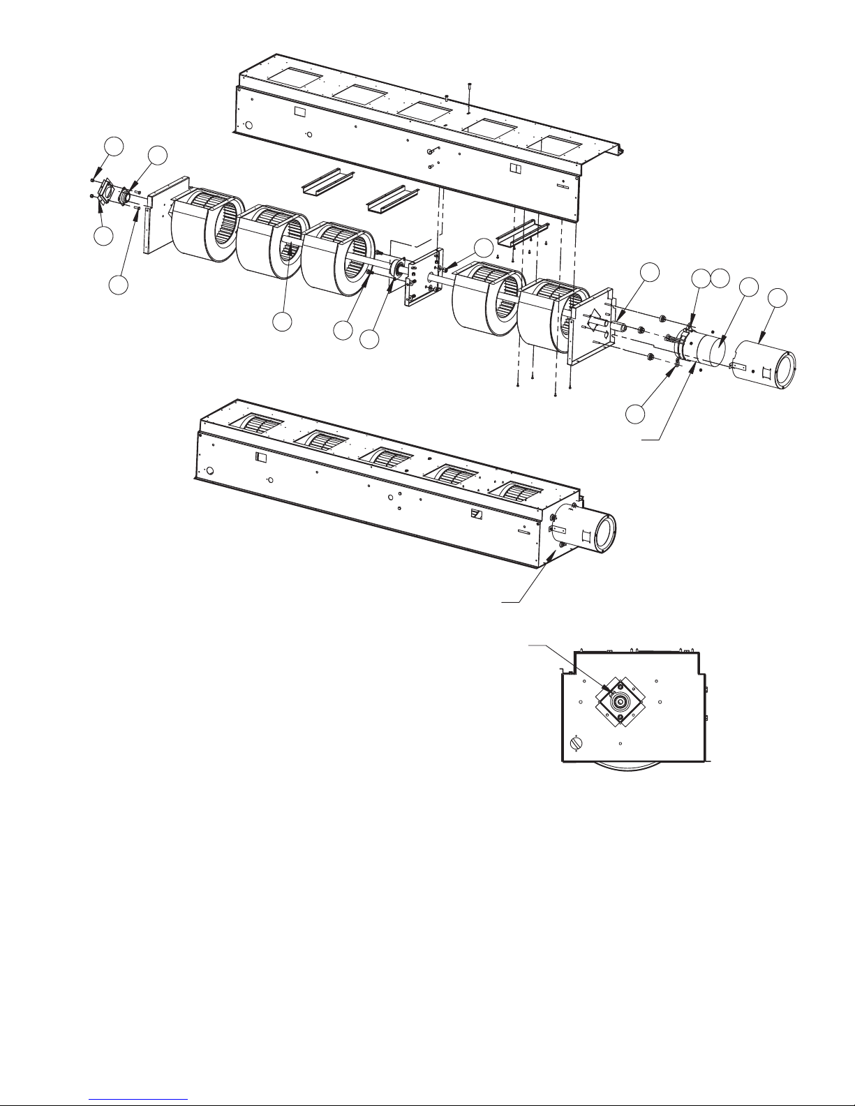
13
14
12
11
10
1
2
9
8
3
4
5
6
7
(SEE NOTE 5)
(SEE NOTE 5)
NOTES:
1. Not all components shown for clarity.
2. This drawing applies to 2000 cfm units only.
3. Remove shaft, motor and coupling prior to removing bearing.
Refer to Removal and Reinstallation instructions.
4. Install sleeve bearing with oil cup facing up and towards the rear of
the assembly.
5. Refer to Fig. 9 for motor-coupling and shaft-coupling tolerances.
Fig. 13 — 40UH200 Ventilator Blower Drive Train Assembly
(SEE NOTE 4)
LEFT SIDE
VIEW
UNIT
BOTTOM
33
Page 34
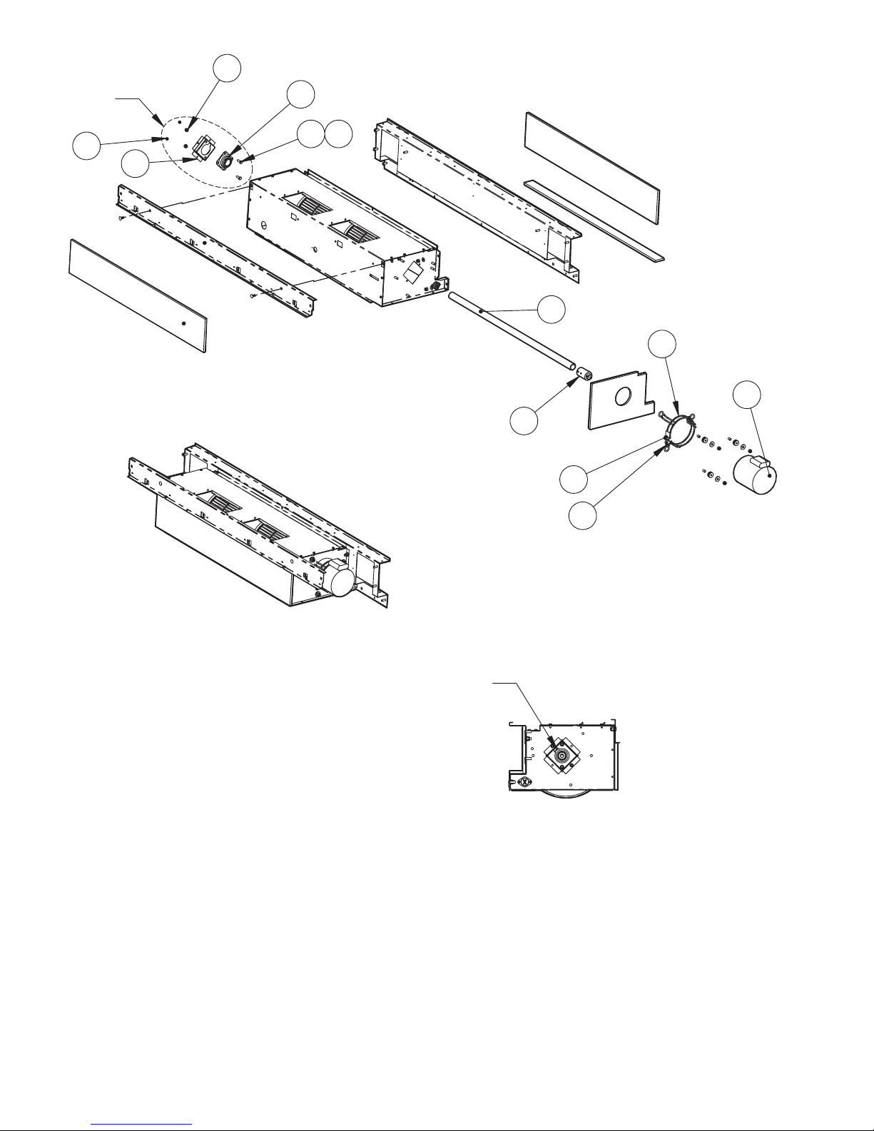
9
SEE NOTE 2
8
10
12
11
7
1
2
(SEE NOTE 3)
3
6
5
NOTES:
1. Not all components shown for clarity.
2. Items no. 7, 16 and associated hardware not required for
40UV,UH150. Refer to Fig. 11 for 40UV,UH150 in-board bearing
replacement.
3. Install motor with capacitor facing up.
4. Install sleeve bearing with oil cup facing up and towards the rear of
the assembly.
Fig. 14 — 40UV,UH Ventilator Blower Drive Train Assembly —
40UV050-150 and 40UH075-150 Units (PSC Motor)
(SEE NOTE 4)
4
UNIT FRONT (40UV)
UNIT BOTTOM (40UH)
34
Page 35
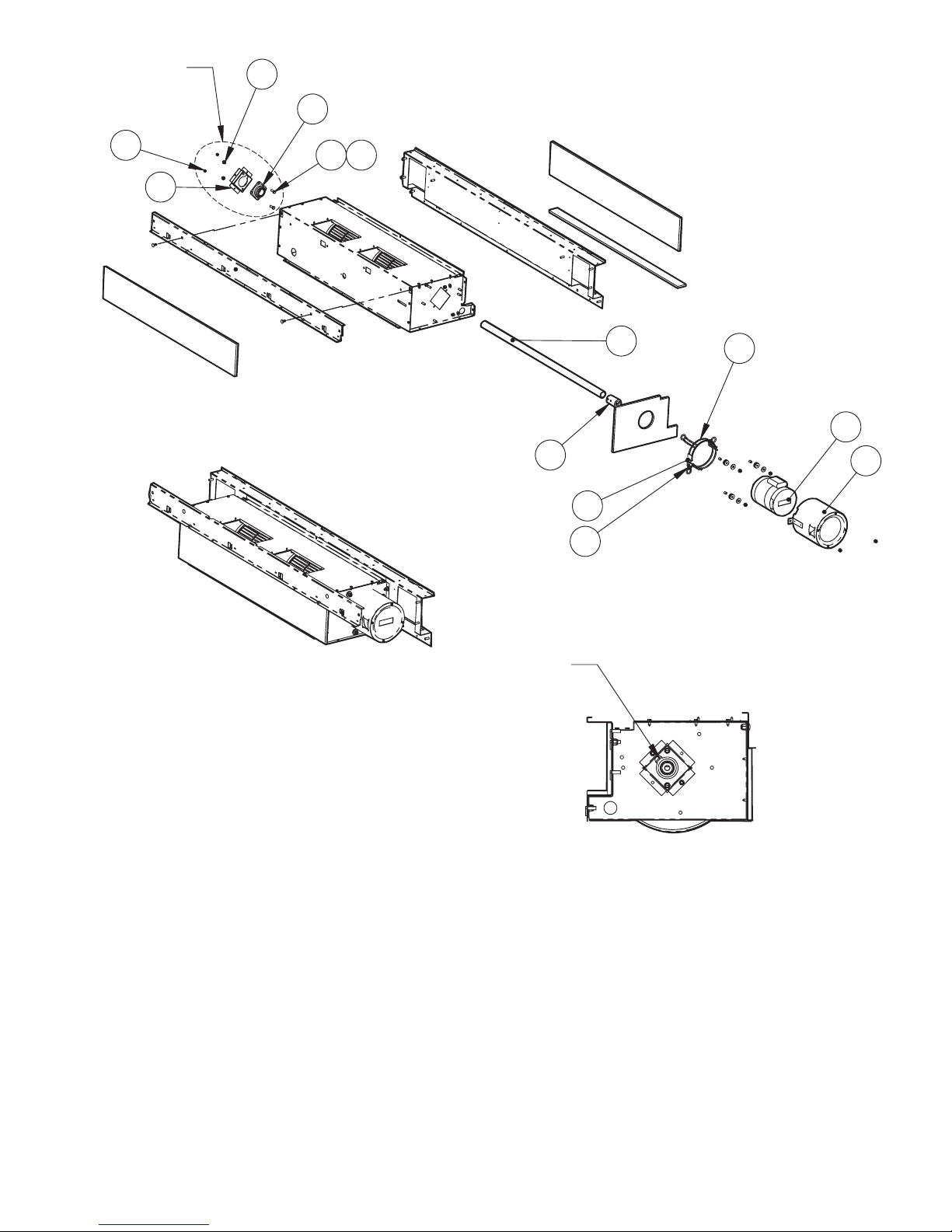
SEE NOTE 2
10
11
9
12
13
8
1
2
3
7
4
6
5
NOTES:
1. Not all components shown for clarity.
2. Items no. 7, 10 and associated hardware not required for
40UV,UH150. Refer to Fig. 11 for 40UV,UH150 in-board bearing
replacement.
3. Install motor with electrical connections facing front of assembly.
4. Install oil cup facing up and towards the rear of the assembly.
Fig. 15 — 40UV,UH Ventilator Blower Drive Train Assembly —
40UV050-150 and 40UH075-150 Units (ECM Motor)
(SEE NOTE 4)
LEFT SIDE
VIEW
UNIT FRONT (40UV)
UNIT BOTTOM (40UH)
35
Page 36
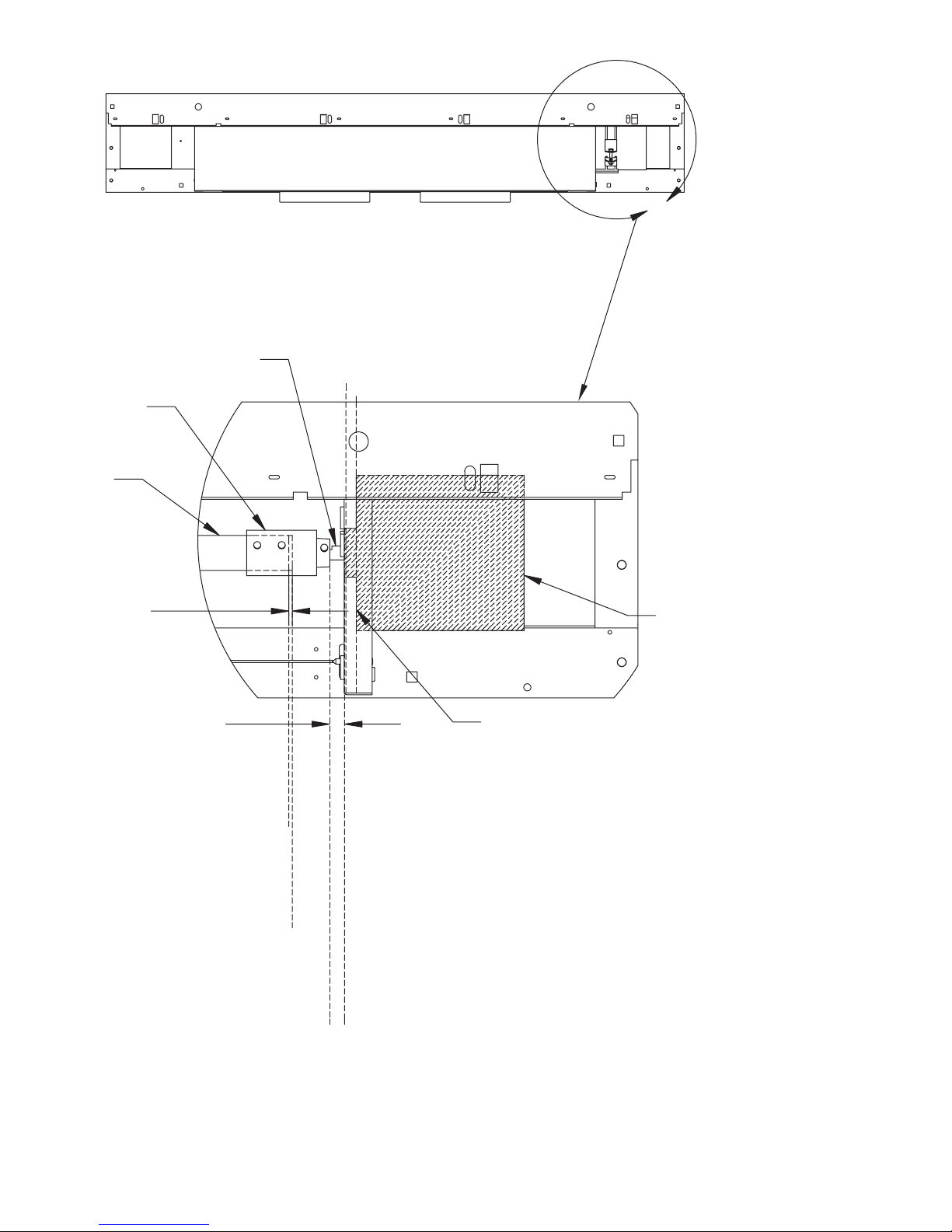
COUPLING
FAN
SHAFT
+
.125 .032
–
BLOWER SECTION
FRONT VIEW
MOTOR SHAFT
MOTOR (PSC)
+
0.500 0.063
–
SHAFTED END FACE
COUPLING INSIDE FACE
COUPLING FACE
MOTOR BEARING FACE
FACE OF MOTOR
FLUSH WITH FACE
OF INSULATION
NOTES:
1. All dimensions shown in inches.
2. Not all components shown for clarity.
Fig. 16 — 40UV,UH Ventilator Blower Section Assembly — PSC Motor Detail
36
Page 37
Sleeve Bearing Replacement (40UV050-125,
40UH075-125 and 40UH200 Units Only)
(Fig. 17) —
Fig. 14 for 40UV050-150 and 40UH075-125 units with PSC
motors, Fig. 15 for 40UV050-125 and 40UH075-150 units
with ECM motors.
Lock out and tag all power supplies to equipment and controls prior to servicing unit. Follow all safety codes. Failure
to do so could result in personal injury.
The assembly order of the bearing installation is critical. Be
careful with all components during removal and installation. Any excessive force applied to these components can
cause unintended damage and void unit warranty
To replace ball bearing:
1. Turn off all power to unit.
IMPORTANT: Tag each right front panel (40UV) or
middle bottom panel (40UH) for each unit. Panels have
electrical information specific to each unit.
2. Use
front (40UV) or bottom (40UH) panels and right (motor
end) end panel.
3. Remove
length of unit that secure coil baffle to blower section and
remove front coil baffle.
4. Remove left blower section end (Item 2 in Fig. 17) insulation (Item 1 in Fig. 17).
5. Use
Fig. 14, Item 8; Fig. 15, Item 9) securing end bearing
bracket (Fig. 13, Item 12; Fig. 14, Item 7; Fig. 15, Item 8)
to blower section end.
6. Remove bearing bracket assembly (Fig. 13, Items 12, 14,
13, 11; Fig. 14, Items 7, 10, 9, 11; Fig. 15, Items 8, 11, 10,
12) from blower section end. Use care to slide assembly
Refer to Fig. 13 for 40UH200 units only,
5
/32in. hex (Allen) tool or3/8in. nut driver to remove
1
/4in. head screws (Item 5 in Fig. 10) along
7
/16in. socket to remove hex nuts (Fig. 13, Item 13;
off of shaft end. Hold shaft from inside blower section
to prevent wheel damage.
7. Use
1
/2in. socket and1/2in. combination wrench to
remove hex nuts (Fig. 13, Item 13; Fig. 14, Item 9;
Fig. 15, Item 10) and bolts (Fig. 13, Item 11; Fig. 14, Item
11; Fig. 15, Item 12) holding bearing (Fig. 13, Item 14;
Fig. 14, Item 10; Fig. 15, Item 11) and bearing bracket
(Fig. 13, Item 12; Fig. 14, Item 7; Fig. 15, Item 8)
together.
Ensure sleeve bearing is installed with oil cup facing
upwards as shown in left side view.
8. Replace bearing (Fig. 13, Item 14; Fig. 14, Item 10;
Fig. 15, Item 11). Attach to bearing bracket using hex
nuts and bolts. Align oil cup port with matching cutout in
bearing bracket.
9. Use
7
/16in. socket to slide replacement bearing (Fig. 13,
Item 14; Fig. 14, Item 10; Fig. 15, Item 11) on to the end
of shaft and install bearing bracket assembly (Fig. 13,
Items 12, 14, 13, 11; Fig. 14, Items 7, 10, 9, 11; Fig. 15,
Items 8, 11, 10, 12) in blower section end. Attach using
hex nuts.
10. Add 5 to 10 drops of SAE 20 or 30 non-detergent based
oil to bearing.
11. Rotate the fan shaft by hand to ensure that fans are
unrestricted and can rotate freely. Check for any fan
obstructions.
12. Reinstall left blower section end insulation (Item 1 in
Fig. 17).
1
13. Reinstall
/4in.headscrews(Item5inFig.10)along
length of unit securing coil baffle to the blower section.
14. Reinstall front (40UV) or bottom (40UH) panels. Reinstall end panels. Ensure that tag on each right front
panel (40UV) or middle bottom panel (40UH) matches unit tag.
15. Restore power to unit.
37
Page 38
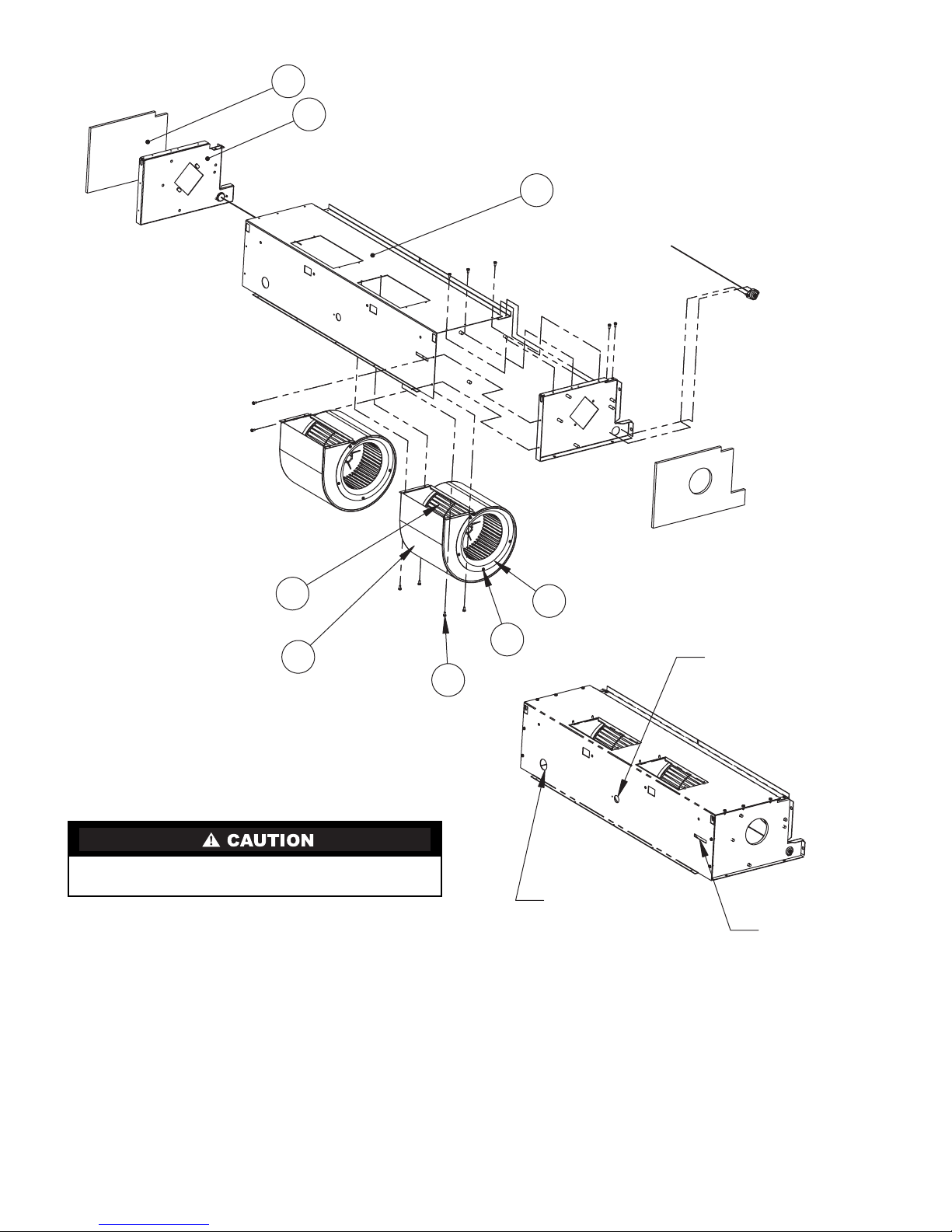
AUTOMATIC RESET
1
HIGH TEMPERATURE
LIMIT SWITCH
(SEE NOTES 2,3)
(SEE CAUTION)
2
3
8
4
MANUAL RESET
HIGH TEMPERATURE
LIMIT SWITCH
(SEE NOTES 2,3)
(SEE CAUTION)
5
7
6
DISCHARGE AIR
TEMPERATURE
SENSOR (OPTIONAL)
OPENING
t
DO NOT CHANGE LIMIT SWITCH CAPILLARY TUBE LOCATION! LIMIT SWITCHES MAY NOT FUNCTION PROPERLY.
NOTES:
1. Not all components shown for clarity.
2. Supplied on electric heat units only.
3. Secure capillary tubes to blower housing using high temperature
cable tie. Capillary tube lengths will vary depending on unit size.
Fig. 17 — 40UV,UH Ventilator Blower Section Assembly Sheet Metal (All Units)
38
RETURN AIR
TEMPERATURE
SENSOR (OPTIONAL)
OPENING
MOTOR AND
COUPLING
SETSCREW
ACCESS
Page 39
Blower Wheel Removal and Reinstallation
(Fig. 17) —
Fig. 14 for 40UV050-150 and 40UH075-125 units with PSC
motors, Fig. 15 for 40UV050-125 and 40UH075-150 units
with ECM motors.
Lock out and tag all power supplies to equipment and controls prior to servicing unit. Follow all safety codes. Failure
to do so could result in personal injury.
The assembly order of the bearing installation is critical. Be
careful with all components during removal and installation. Any excessive force applied to these components can
cause unintended damage and void unit warranty.
To remove blower wheel:
1. Turn off all power to the unit.
2. Remove blower section per service instructions in Blower
Assembly Removal and Reinstallation.
IMPORTANT: Tag each right front panel (40UV) or
middle bottom panel (40UH) for each unit. Panels have
electrical information specific to each unit.
3. Use
wheels (two per wheel).
4. Loosen inboard/center bearing setscrews (only on
40UV,UH150 and 200 size units).
5. If unit has ECM motor, remove motor shroud (sheet
metal cover — Fig. 13, Item 6; Fig. 14; Fig. 15, Item 4)
by removing two
ing shroud.
6. Loosen
Item 2; Fig. 15, Item 2), nut (Fig. 13, Item 3; Fig. 14,
Item 5; Fig. 15, Item 6), and bolt (Fig. 13, Item 4; Fig. 14,
Item 4; Fig. 15, Item 5), until motor housing (Fig. 13,
Item 5; Fig. 14, Item 3; Fig. 15, Item 3) moves freely.
7. Slide shaft-coupling-motor assembly (Fig. 11, Items 3, 2,
1; Fig. 13, Items 5, 2, 10) out of wheels and unit until
shaft clears inboard/center bearing assembly (30 in. maximum clearance required from edge of frame end).
8. Remove four
blower housing(s) (Fig. 17, Item 7) to blower deck
(Fig. 17, Item 3) and remove blower and wheel assembly.
9. Remove five
blower inlet ring (Fig. 17, Item 4) to blower housing and
remove inlet ring.
10. Remove blower wheel(s) (Fig. 17, Item 8).
To reinstall blower wheel:
1. Install new blower wheel(s) (Fig. 17, Item 8). Ensure that
the fan blades are installed in the correct orientation (cup
of blade towards discharge).
2. Install inlet ring (Fig. 17, Item 4) and install five ¼ in.
head screws (Fig. 17, Item 5) securing blower inlet ring to
blower housing (Fig. 17, Item 7).
3. Install four
blower housing(s) (Fig. 17, Item 7) to blower deck
(Fig. 17, Item 3).
Refer to Fig. 13 for 40UH200 units only,
5
/32in. hex tool to loosen setscrews on all blower
5
/16in. hex nuts. Do not discard cool-
5
/16in. motor mount (Fig. 13, Item 7; Fig. 14,
1
/4in. head screw (Fig. 17, Item 6) securing
1
/4in. head screws (Fig. 17, Item 5) securing
1
/4in. head screws (Fig. 17, Item 6) securing
4. Slide shaft-coupling-motor assembly (Fig. 11, Items 3, 2,
1; Fig. 13, Items 5, 2, 10) back into bearing and wheels.
Do not use excessive force. Damage to wheels may
occur.
5. Insert shaft-coupling-motor assembly into wheels until
motor clearance is as specified for motor type (PSC or
ECM). See Fig. 16 or Fig. 9.
6. Ensure that motor shaft is perpendicular to motor blower
endplate. Tighten
5
/16in. motor mount (Fig. 13, Item 7;
Fig. 14, Item 2; Fig. 15, Item 2), nut (Fig. 13, Item 3;
Fig. 14, Item 5; Fig. 15, Item 6), and bolt (Fig. 13, Item 4;
Fig. 14, Item 4; Fig. 15, Item 5), until motor (Fig. 13,
Item 5; Fig. 14, Item 3; Fig. 15, Item 3) is secure.
7. Install motor shroud (sheet metal cover — Fig. 13,
Item 6; Fig. 14; Fig. 15, Item 4) using two
5
/16in. hex nuts
if using ECM motor. Align “window” with receptacles on
motor. Motor control module could overheat and fail if
operated without cooling shroud.
8. Reinstall blower section into frame assembly. See Fig. 10.
5
9. Tighten the four
/16in. nuts retaining blower section to
frame.
5
10. Tighten the two
/16in. (Fig. 11, Item 6) nuts retaining the
inboard bearing bracket to the pipe chase (only on
40UV,UH150 and 200 size units).
11. Reinstall two carriage bolts (Fig. 10, Item 6) that attach
the front brace to the frame sides.
12. Re-attach green ground wire that connects the motor to
the frame with
1
/4in. head screw if unit has a PSC motor.
ECM motors are grounded through the harness.
13. Re-attach wiring harness connector(s) to motor.
14. Center each wheel in its respective housing and tighten
wheel setscrews (two for each wheel).
1
15. Reinstall one
/4in. head screw (Fig. 10, Item 1) at center
of blower deck attaching blower deck to pipe chase.
16. Reinstall the four
1
/4in. head screws (Fig. 10, Item 2)
holding the blower section sides to the coil section sides.
17. Rotate the fan shaft by hand to ensure that fans are
unrestricted and can rotate freely. Check for any fan
obstructions.
18. Remove lockout and operate unit for approximately
60 seconds to let inboard/center bearing mount self-adjust
(only on 40UV,UH150 and 200 size units).
19. Lock out and tag all power supplies to equipment and
controls. Tighten the two bearing setscrews (only on
40UV,UH150 and 200 size units). See Fig. 11, 13 or 17.
1
20. Reinstall the coil baffle using the six
/4in. head screws
that attach the coil baffle to the coil section. See Item 4 in
Fig. 10.
1
21. Reinstall
/4in. head screws along length of unit securing
coil baffle to the blower section. See Item 5 in Fig. 10.
22. Reinstall optional vanes and screens and install top panel
(40UV). Reinstall top (40UV) or front (40UH) discharge
plenum and ductwork if required or discharge grille.
23. Reinstall front (40UV) or bottom (40UH) panels. Reinstall end panels. Ensure that tag on each right front
panel (40UV) or middle bottom panel (40UH) matches unit tag.
24. Restore power to unit.
39
Page 40
Damper Section Removal and Reinstallation
(Fig. 18)
Lock out and tag all power supplies to equipment and controls prior to servicing unit. Follow all safety codes. Failure
to do so could result in personal injury.
The assembly order of the bearing installation is critical. Be
careful with all components during removal and installation. Any excessive force applied to these components can
cause unintended damage and void unit warranty.
To remove damper section:
1. Turn off all power to unit.
IMPORTANT: Tag each right front panel (40UV) or
middle bottom panel (40UH) for each unit. Panels have
electrical information specific to each unit.
5
2. Use
3. Remove four carriage bolts and nuts securing kickplate to
IMPORTANT: Tag kickplate for each unit. Kickplate
has electrical information specific to each unit.
/32in. hex (Allen) tool or3/8in. nut driver to remove
front (40UV) or bottom (40UH) panels and right end
panels.
end frames.
4. Remove the two
1
/4in. head screws securing kickplate to
the damper sides (one on each side) and remove
kickplate.
5. Remove
1
/4in. head screws attaching outside air (OA)
actuator to damper shaft or attaching locking quadrant assembly to damper shaft. Remove OA actuator or locking
quadrant assembly.
1
6. Remove six
/4in. head screws (3 per side) securing
damper to 40UH unit rear panel.
7. Remove two
5
/16in. nuts attaching damper assembly to
back frame.
8. Remove damper assembly from unit.
To replace damper section:
1. Replace damper assembly into unit.
2. Replace
5
/16in. nuts attaching damper assembly to back
frame.
1
3. Replace six
/4in. head screws (3 per side) securing
damper to 40UH unit rear panel.
4. Replace
1
/4in. head screws attaching OA actuator to
damper shaft OR attaching locking quadrant assembly to
damper shaft. Replace OA actuator or locking quadrant
assembly.
1
5. Replace the two
/4in. head screws securing kickplate
to the damper sides (one on each side) and remove
kickplate.
6. Replace four carriage bolts and nuts securing kickplate to
end frames.
7. Reinstall front (40UV) or bottom (40UH) panels. Reinstall end panels. Ensure that tag on each right front
panel (40UV) or middle bottom panel (40UH) matches unit tag.
8. Restore power to the unit.
40
Page 41
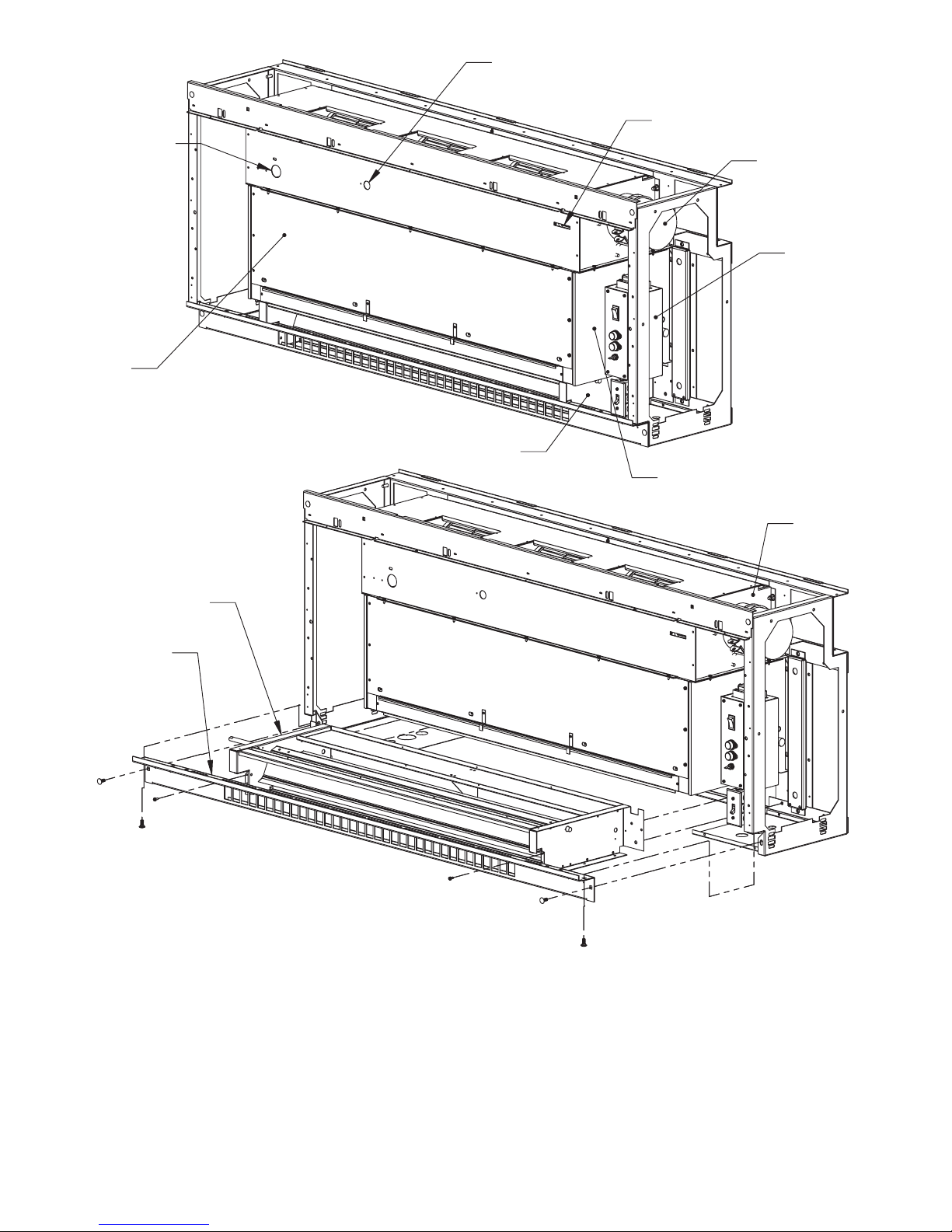
RETURN AIR
TEMPERATURE
SENSOR
OPENING
FRONT
COIL
BAFFLE
DISCHARGE AIR
TEMPERATURE SENSOR
OPENING
DAMPER SECTION
MOTOR & COUPLING
SETSCREW ACCESS
COIL SECTION
MOTOR
MOTOR
ELECTRICAL
BOX
DAMPER SECTION
KICKPLATE
NOTES:
1. Unit shown in vertical orientation. Drawing applies to horizontal and vertical units.
2. Not all components shown for clarity.
BLOWER SECTION
Fig. 18 — 40UV,UH Ventilator Damper Section Removal/Installation
41
Page 42

Page 43

Page 44
Copyright 2005 Carrier Corporation
Manufacturer reserves the right to discontinue, or change at any time, specifications or designs without notice and without incurring obligations.
Book 3
Ta b 2 a
Catalog No. 534-095 Printed in U.S.A. Form 40UV,UH-7SI Pg 44 5-05 Replaces: 40UV,UH-2SI
 Loading...