

Page 1
38QP024/40RR024
Heat Pump System
HEATING & COOLING
Installation, Start-Up and Service Instructions
Piping Package No. 40RR900271
50/60 Hz
NOTE: Read and become familiar with these instructions
before beginning installation.
SAFETY CONSIDERATIONS
Installing and servicing air-conditioning equipment can
be hazardous due to system pressures and electrical com
ponents. Only trained and qualified service personnel should
install or service air-conditioning equipment. When work
ing on air-conditioning equipment, observe the precautions
provided in literature, and on tags and labels attached to the
unit.
A WARNING
Electrical shock can cause personal injury or death.
Before beginning any modification or installation of this
package, be sure the main electrical disconnect is in
the off position. Ensure power is disconnected to the
fan coil unit. On some systems both the fan coil and
the outdoor unit may be on the same disconnect. Tag
the disconnect switch with a suitable warning label.
GENERAL
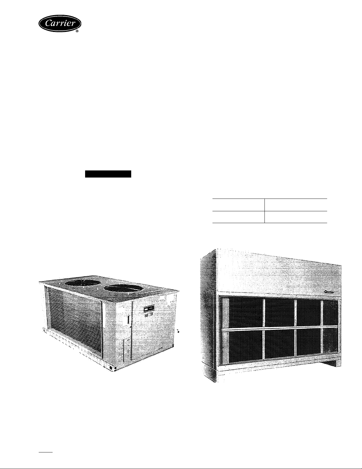
The accessory heat pump piping package is designed for
use with the Carrier 38QP024 heat pump (outdoor section)
in combination with the 40RR024 fan coil unit (indoor
section) (see Fig. 1).
Special accessories are available for electrical control of
this system. Electric heaters for the 40RR024 are a fieldinstalled accessory. Ensure that all material required for
installation is available at the jobsite, including the 38QP024
outdoor section, the 40RR024 indoor section, piping pack
age, electrical control package, and 40RT electric heater
packages. The Sporlan part no. G8 nozzle is used for both
the upper (circuit no. 2) and lower (circuit no. 1) coil sec
tions of the indoor unit. Nozzles are shipped as standard
parts of the factory-installed 40RR distributor. Distributor
sizes are as follows:
COIL SECTION
Upper (Ckt 2)
Lower (Ckt 1)
DISTRIBUTOR SIZE
(in. OD)
7/8
7/8
OUTDOOR SECTION
38QP024
Fig. 1 — 38QP024/40RR024 Heat Pump System
Manufacturer reserves the right to discontinue, or change at any time, specifications or designs without notice and without Incurring obligations.
Book 11 PC 111 Catalog No 563-710 Printed in U.S. A Form 38QP-5SI Pg 1 11-92 Repiaces: New
Tab 5a
INDOOR SECTION
40RR024
Page 2
Accessories
PIPING PACKAGE — Contains check valves, thermo
static expansion valves (TXV’s), receiver, filter driers, and
tubing to connect the indoor coils for heat pump service.
THERMOSTAT HH07AT172 (HH07AT162 For Use on
Celsius Scale) — Used with subbase HH93AZ174, is a 2-stage
cool/2-stage heat thermostat with automatic changeover and
a lockout light. There is no provision for emergency heat.
THERMOSTAT HH07AT172 (HH07AT162 For Use on
Celsius Scale) — Used with subbase HH93AZ177, is a 2-stage
cool/2-stage heat thermostat. This combination has all the
features of HH07AT172 (HH07AT162)/HH93AZ174 plus
a provision for emergency heat.
SEQUENCER PACKAGE — Can be used with this system
when unloaders are added to the compressor(s). (Unloading
can be applied in the cooling cycle only. Unloading can
never be applied in the heating cycle.) The sequencer has
4-stage cooling capability.
ELECTRIC HEATERS — May be used with the 40RR in
door unit (see Table 1). Use a maximum of four 20-kW
(at 240 v) or 21.8-kW (at 480 v) electric heater assemblies.
ELECTRIC HEATER CONTROL PACKAGE 40RT900081
— Provides control for up to 3 stages of electric heat when
used with outdoor-air thermostat(s). Package must be used
whenever 40RT electric heaters are utilized. If a fourth
stage of electric heat is used, an additional field-supplied
heater control relay is necessary. This relay must have a
24-V coil with 230-v contacts. Outdoor thermostats
(part no. HH22QA040) are recommended for staging elec
tric heaters.
Table 1 — Unit 40RR Accessory Electric Heaters
PART NO.
40RT-900-101 240 20.0
40RT-900-111 480
LEGEND
FLA — Full Load Amps
NOTES;
1. A maximum of 4 electric heaters can be used with the 40RR024
unit.
2 Electric heaters are not UL (Underwriters’ Laboratories) listed for
the 38QP/40RR heat pump.
WATTAGE MULTIPLICATION FACTORS
Heater Voltage
Rating
240
480
Example: 20.0 kW (at 240 v) heater on 230 v
= 20.0 (0.92 multiplication factor)
= 18.4 kW capacity at 230 v
ELECTRIC HEATER (3 PHASE 50/60 Hz)
Rated
Voltage
Actual Heater
Voltage
(3 Phase, 50/60 Hz)
200 0.69
208 0.75
220
230
240 1.00
380
400 0 69
415
440
460
480 1.00
kW
21.8
FLA
48 0
26.0
Multiplication
Factor
0.84
0.92
0.63
0.75
0.84
0.92
INSTALLATION
Step 1 — Perform Outdoor and Indoor Unit
Installation — Follow the installation instructions pro
vided with each outdoor and indoor unit. See Table 2 for
maximum vertical elevation between the indoor and out
door sections.
Table 2 - Maximum Vertical Separation
HEIGHT OF INDOOR UNIT
SYSTEM
40RR024/38QP024,
60 Hz, Ckt 1 and 2
40RR024/38QP024,
50 Hz, Ckt 1 and 2
Above Outdoor
Unit
ft
59
58
m
180
17.7
Below Outdoor
Unit
ft m
59
58
18.0
17.7
Step 2 — Size Piping Lines — Employ one of the
following methods to size interconnecting refrigerant pip
ing between the 38QP and the 40RR:
1. Use the pipe sizes shown in Refrigerant (R-22) Charge
and Piping Selection table in the 38QP installation in
structions (when not using field-installed accessory un
loaders).
2. Use the Carrier System Design Manual, Part 3, Piping
Design (when using field-installed accessory
unloaders).
3. Use the piping sizing portion of the Carrier E20-II com
puter program (when using field-installed accessory
unloaders).
NOTE: Liquid line solenoid valves are not required; they
are factory-installed on the 38QP.
Step 3 - Check Contents of Piping Package
— Install heat pump piping package to convert indoor coil
for heat pump service. Table 3 lists the contents of the pip
ing package. Figure 2 shows the contents of the piping pack
age in the approximate order in which they are installed.
Table 3 — Heat Pump Piping Package Contents
DESCRIPTION
Receiver, Piping Assy (Ckt 1)
Piping Assy (Ckt 2)
Filter Drier (Ckt 1 and 2)
Receiver, Piping Assy Support Bracket
(Cktl)
Filter Drier Support Bracket (Ckt 2)
TXV (Thermostatic Expansion Valve)
(Ckt 1 and 2)
Screw, Receiver Strap*
Screws, No. 10 for Filter Drier Strap (4)
5/8" Tube Clamp (2), Filter Drier Support
Bracket (2)*
Tube, Filter Drier to TXV (Ckt 1)
Tube, Filter Drier to TXV (Ckt 2)
Strapping, 11" Long for Filter Driers
(Ckt 1 and 2)
Strapping, 10" Long for Receiver (Ckt 1)
Clamp for 5/8" OD Tube (Ckt 1)
Installation Instructions* 1
Strap for TXV Sensort
Screw and Nut for TXV Strapt
‘Items are included in a packet which accompanies piping package,
titems are packed together with TXV.
QUANTITY
1
1
2
1
1
2
1
8
1
1
2
1
1
2
2
Page 3

(CKT 2)
PIPING ASSY (CKT 2)
RECEIVER, PIPING
ASSY (CKT 1)
TXV — Thermostatic Expansion Valve
NOTE: Items listed in Tabie 1 and not shown on Fig 2 are inciuded
in packaging which accompanies piping package.
Fig. 2 - Heat Pump Piping Package Contents in Approximate Order of Installation
Page 4

Step 4 — Install Piping Package — install parts of
piping package as shown in Fig. 3.
CONNECT LIQUID AND VAPOR LINES - Run liquid
and vapor lines separately between the 38QP and the 40RR
units, because the 38QP has dual independent refrigerant
circuits. A label on the 38QP comer post identifies the
circuits.
CONNECT EQUALIZER LINE TO EACH THERMO
STATIC EXPANSION VALVE (TXV) - (See Fig. 4.)
Install a fitting for suction pressure readings near the indoor
section to allow for TXV superheat adjustments. (A fitting
can be installed in the equalizer line for this purpose.)
MOUNT TXV SENSING BULB - Locate TXV sensing
bulb on the suction line as shown in Fig. 4. Do not attach
bulb to suction manifold (header). Locate bulb on a vertical
riser where possible. If a horizontal location is necessary,
secure the bulb at approximately 4 o’clock or 8 o’clock
position. (See Fig. 5.)
Step 5 — Connect Power Wiring — All wiring
must comply with local and National Electrical Code re
quirements. See the installation instructions with each in
door and outdoor unit for recommended wire and fuse sizes.
See 38QP wiring book for wiring diagrams and Table 4 for
40RR wire MCA (minimum circuit amps) and MOCP (max
imum overcurrent protection). Perform charging instruc
tions per installation instructions provided with the outdoor
unit.
‘40RR024 Only.
Fig. 4
Equalizer Line and TXV Sensing Bulb
Locations
TXV — Thermostatic Expansion Valve
NOTE: Cut distributor side outlet tube to 1-5/16 in. (33.3 mm) length from OD of distributor.
Fig. 3 — Unit 40RR Piping Arrangement
Page 5

VAPOR LINE
TXV — Thermostatic Expansion Valve
NOTE: The 8 o’clock position is shown above
Fig. 5 — TXV Feeler Bulb Locations
Step 6 — Make TXV Adjustments.
A CAUTION
Wait 30 minutes between TXV adjustments to avoid
excessive superheat.
Make TXV adjustments on 40RR after installation of pip
ing package, verifying 10° F superheat.
Table 4 — Unit 40RR Electrical Data
FAN
V*-PH-HZ
UNIT
024
208-3-60
230-3-60
460-3-60t
LEGEND
40RR
FLA — Full Load Amps
MCA — Minimum Circuit Amps
MOCP — Maximum Overcurrent Protection
‘Motors are designed for satisfactory operation at ± 10% of nominai
voitages shown. Voitages should not exceed the limits shown in the
“Voltage Limits” column.
fMotors must be field wired for 460 v in accordance with directions
on nameplate of motor.
NOTE: Fan motors are field supplied on unit 40RR024 (575 v) and
on 50-Hz units.
VOLTAGE
LIMITS
180-220
207-253
416-528 5.0
MOTOR
FLA
Hp
3 10.8
10.1
3
POWER
SUPPLY
MCA
132
11.5
58
MOCP
(Amps)
15
15
NOTE: Because this split system uses TXV’s in the heating
cycle, refrigerant charge can be adjusted during heating op
eration. When properly charged, the 40RR has approxi
mately 32° F of state point subcooling leaving circuits no.
1 and 2 from the indoor coil in the heating cycle. Use charg
ing chart on unit to complete charging (in cooling cycle
only).
NOTE: Use refrigerant R-22 only.
NOTE: Since the 38QP unit contains 2 refrigeration
circuits, both circuits must be charged separately.
To charge system:
1. Regulate valve at refrigerant (R-22) tank to maintain suc
tion pressure at 80 psig (551.6 kPa) while charging. Charge
with vapor only at suction side of unit.
NOTE: Do not depend on sight glass when charging unit;
use charging charts which are attached to the inside of each
compressor access panel.
2. Measure line temperature close to the liquid service valve,
and measure the pressure at the Schrader port on the liq
uid line service valve. Plot point on the charging chart.
If point is above the line, add charge. If point is below
the line, remove and reclaim charge until operating point
falls on the curve.
3. Allow system to operate for 20 minutes. Take tempera
ture and pressure reading at liquid service valve and check
values with the charging chart.
4. Record final installed system charge in ink on unit
nameplate.
CHECK OIL CHARGE — Allow system to run for approx
imately 20 minutes. Stop system and check compressor oil
level. Ten pints is the proper oil charge amount for a 6D
compressor. Add oil only if necessary to bring oil into view
in sight glass. Use only Carrier-approved compressor oil:
Petroleum Specialties
Texaco, Inc
.......................................................
Witco Chemical Corp
..........................................
.........................................
Cryol 150A
Capella WE32
Sunisco 3GS
IMPORTANT: Do not reuse drained compressor oil
or oil that has been exposed to atmosphere. Proce
dures for adding oil are given in GTAC II, Module 5,
Charging, Recovery, Recycling, and Reclamation. To
remove oil: shut system off; isolate the compressor;
remove and reclaim the refrigerant in the compressor;
remove the compressor oil drain plug.
START-UP
Evacuate and Dehydrate — Evacuate and dehy
drate entire refrigerant system as shown in General Train
ing Air Conditioning (GTAC) II, Module 4, System
Dehydration.
A WARNING
To prevent personal injury, wear safety glasses and gloves
when handling refrigerant. Do not overcharge system
— this can cause compressor flooding. Never charge
liquid into the low-pressure side of the system. During
charging or removal of refrigerant, be sure indoor fan
system is operating.
Preliminary Charge — Refer to GTAC II, Module 5,
Charging, Recovery, Recycling, and Reclamation for charg
ing methods and procedures. Charge system per Table 1 in
GTAC II by the liquid charging method and charging by
weight procedure.
Charge System (Cooling Only) — Refer to GTAC
II, Module 5, Charging, Recovery, Recycling, and Recla
mation, and the following procedure.
SEQUENCE OF OPERATION
General — The heat pump contains 2 independent re
frigeration circuits. Each circuit has its own set of indepen
dent controls, compressor, liquid line solenoid valve, re
versing valve, crankcase heater, TXV, and accumulator.
Circuit breakers provide overcurrent protection for com
pressors (in both heating and cooling modes). These re
quire manual reset at the 38QP unit control box. The oil
pressure safety and crankcase heater also require reset at
the outdoor unit.
Cooling
NOTE: When power is supplied to a system that is off,
crankcase heaters are energized. The reversing valve may
or may not be energized depending on mode of operation
(heating or cooling) when thermostat was previously
satisfied.
The following cooling operating sequence has both heat
pump circuits connected to a single, 2-circuit fan coil. The
system is controlled by a single 2-stage heat/2-stage cool
thermostat.
Page 6

When the thermostat calls for first-stage cooling (TCI
closed), the indoor-fan motor starts immediately. Compres
sor no. 1 and outdoor fan no. 1 start after 3 seconds and
before 5 minutes depending on the length of time system is
off after thermostat was previously satisfied. (This time pro
cess is effective because of the 5-minute Time Guard® II
circuit.) The reversing valve solenoid (RVSl) deenergizes,
causing the reversing valve to shift to the cooling position.
The crankcase heater is off when the compressor is operat
ing. The liquid line solenoid valve in circuit no. 1 opens,
allowing refrigerant to flow.
When the thermostat calls for second-stage cooling (TC2
closed), compressor no. 2 and outdoor fan no. 2 start. The
reversing valve solenoid (RVS2) is deenergized, causing the
reversing valve to shift to the cooling position. The liquid
line solenoid in circuit no. 2 opens, allowing refrigerant
flow in circuit no. 2.
When the second stage of thermostat is satisfied (TC2),
compressor no. 2 shuts off and outdoor-fan motor no. 2
shuts off. When the first stage of thermostat is satisfied,
compressor no. 1, outdoor fan no. 1, and indoor fan shut
off. The liquid line solenoid valve closes in each refriger
ation circuit when the corresponding compressor shuts off.
The reversing valves do not shift but remain in the cooling
position until there is a call for heating.
The unit is equipped with a no-dump reversing valve logic.
When the unit is in the cooling mode, the reversing valve
remains in cooling mode position until the thermostat calls
for heating Conversely, when the unit is in the heating mode,
the reversing valve remains in heating mode position until
the thermostat calls for cooling.
NOTE: If a malfunction occurs, causing the high-pressure
switch (HPS), compressor overtemperature (COTP) safety,
or loss-of-charge switch (LCS) to open, the compressor in
the affected circuit is locked out by a Cycle-LOC™ circuit.
This causes the Signal-LOC™ warning light to come on at
the thermostat subbase. The remaining refrigeration circuit
continues to operate. The RVS remains deenergized on the
inactive circuit so reversing valve does not shift. These safe
ties are reset by adjusting the thermostat up to open TCI
and TC2, or by momentarily switching thermostat subbase
to OFF position. If the compressor oil pressure is lost, or if
oil pressure fails to build on start-up on either refrigeration
circuit, an oil-pressure safety switch shuts off the affected
compressor. The switch must be reset manually at the unit.
When the thermostat calls for heating (THl closed), the
indoor-fan motor starts. Compressor no. 1 and outdoor fan
no. 1 start after 3 seconds and before 5 minutes depending
on the length of time system is off after thermostat is sat
isfied. (The time process is effective because of the 5-minute
Time Guard II circuit.) The liquid line solenoid valve for
circuit no. 1 opens when compressor no. 1 operates and
closes when compressor no. 1 is off. The reversing valve in
circuit no. 1 shifts (RVSl energized) for heating operation.
When the thermostat for second stage of heating closes (TH2),
compressor no. 2 and outdoor fan no. 2 start, liquid line
solenoid no. 2 opens, and reversing valve in circuit no. 2
shifts (RVS2 energized).
When thermostat TH2 is satisfied, compressor no. 2 shuts
off, liquid line solenoid no. 2 closes, and outdoor fan no. 2
shuts off. When thermostat THl is satisfied, compressor
no. 1, outdoor-fan motor no. 1, and indoor-fan motor shut
off, and liquid line solenoid valve no. 1 closes. The revers
ing valves remain in the heating position until there is a call
for cooling.
If either circuit is locked out, the electric heater (if in
stalled) will be energized as long as the thermostat contin
ues to call for heat.
Defrost — An outdoor coil temperature of 28 F (-2 C)
triggers operation of the defrost timer logic on either circuit
so that defrost becomes automatic with a time sequence,
adjustable at 30, 50, or 90 minutes. As long as the outdoor
coil temperature remains below 28 F (-2 C), defrost occurs
every 30, 50, or 90 minutes on that circuit depending on
the time selected. When defrost is initiated, the heat pump
reverts to a modified cooling mode of operation (the out
door fan for the affected circuit shuts off). This modified
cooling mode utilizes heat rejection from the refrigerant to
melt any ice or frost on the outdoor coil. When defrost is
initiated on circuit no. 1, RVSl is energized and shifts the
reversing valve on this circuit. If defrost is not called for on
circuit no. 2, this circuit continues to run in heating until
enough frost or ice is built up on the coil to initiate defrost.
Circuits no. 1 and no. 2 reversing valves shift indepen
dently of one another, because the coil temperatures are sensed
independently. (TDFl [thermistor, defrost 1] is attached to
circuit no. 1, and TDF2 is attached to circuit no. 2.)
Defrost for circuits no. 1 and no. 2 is also terminated in
dependently. When temperature of either outdoor coil reaches
68 F (20 C) or length of defrost time exceeds 10 minutes,
the reversing valve on that circuit shifts back to heating mode
IMPORTANT: Do not reset more than once! If oil
pressure switch trips, determine cause and correct. Do
not bypass oil pressure safety switch.
of operation and the outdoor fan on that circuit restarts.
NOTE: If a malfunction occurs, causing the HPS, COTP,
or LCS to open, the compressor in the affected circuit is
locked out by a Cycle-LOC^“ circuit. This causes a Signal-
The crankcase heaters are in an electrical lockout circuit.
If a crankcase heater is defective, the compressor is locked
off. The compressor remains off until the crankcase heater
is replaced. This lockout circuit cannot be reset by adjust
ing the thermostat.
LOC™ warning light to come on at the subbase. The re
maining refrigeration circuit continues to operate. The RVS
remains energized so reversing valve does not shift. SignalLOC device resets by adjusting thermostat down to open
THl and TH2, or by momentarily switching thermostat sub
base to the OFF position. If compressor oil pressure is lost
or if oil pressure fails to build on start-up on either refrig
Heating
NOTE: When power is supplied to a system that is off, the
crankcase heaters are energized. The reversing valve may
or may not be energized depending on mode of operation
(heating or cooling) when the thermostat was previously
satisfied.
The following heating operating sequence has both heat
pump circuits connected to a single, 2-circuit fan coil. The
system is controlled by a single 2-stage heat/2-stage cool
thermostat.
Copyright 1992 Carrier Corporation
Manufacturer reserves the right to discontinue, or change at any time, specifications or designs without notice and without incurring obligations.
Book 11 PC 111 Catalog No 563-710 Printed in U S. A Form 38QP-5SI Pg 6 11-92 Replaces; New
Tab 5a
eration circuit, an oil-pressure safety switch shuts off the
affected compressor. The switch must be reset manually at
the unit.
IMPORTANT: Do not reset more than once! If oil
pressure switch trips, determine cause and correct. Do
not bypass oil pressure safety switch.
If crankcase heater is defective, the compressor in the af
fected circuit is locked off. The circuit remains off until the
crankcase heater is replaced.
 Loading...