

Page 1
40QAC / 38HDR
40QAQ / 38QRR
Ceiling---Suspended Duct Free S plit System
Sizes 018 to 060
Installation Instructions
40QAC, QAQ Unit
SAFETY CONSIDERATIONS
Improper installation, adjustment, alteration, service, maintenance,
or use can cause explosion, fire, electrical shock, or other
conditions which may cause death, personal injury, or property
damage. Consult a qualified installer, service agency, or your
distributor or branch for information or assistance. The qualified
installer or agency must use factory--authorized kits or accessories
when modifying this product. Refer to the individual instructions
packaged with the kits or accessories when installing.
Follow all safety codes. Wear safety glasses, protective clothing,
and work gloves. Use quenching cloth for brazing operations.
Have fire extinguisher available. Read these instructions
thoroughly and follow all warnings or cautions included in
literature and attached to the unit. Consult local building codes and
current editions of the National Electrical Code ( NEC ) NFPA 70.
In Canada, refer to current editions of the Canadian electrical code
CSA 22.1.
Recognize safety information. This is the safety--alert symbol
When you see this symbol on the unit and in instructions or
manuals, be alert to the potential for personal injury. Understand
these signal words; DANGER, WARNING, and CAUTION. These
words are used with the safety--alert symbol. DANGER identifies
the most serious hazards which will result in severe personal injury
or death. WARNING signifies hazards which could result in
personal injury or death. CAUTION is used to identify unsafe
practices which would result in minor personal injury or product
and property damage. NOTE is used to highlight suggestions
which will result in enhanced installation, reliability, or operation.
!
!
the environmentally sound refrigerant
38HDR, QRR Unit
NOTE: Read the entire instruction manual before starting the
installation.
!
WARNING
UNIT OPERATION AND SAFETY HAZARD
Failure to follow this warning could result in personal injury or
equipment damage.
Puron refrigerant systems operate at higher pressures than
standard R--22 systems. To avoid damage to the unit or
possible personal injury, do not use R--22 service equipment or
components on Puron refrigerant equipment.
!
ELECTRICAL SHOCK HAZARD
Failure to follow this warning could result in personal
injury or death.
Before installing, modifying, or servicing system, main
electrical disconnect switch must be in the OFF
position. There may be more than 1 disconnect switch.
Lock out and tag switch with a suitable warning label.
PERSONAL INJURY AND EQUIPMENT DAMAGE
HAZARD
Failure to follow this caution may result in personal injury
and / or equipment damage.
DO NOT operate the unit without a filter or with grille
removed.
WARNING
!
CAUTION
Page 2
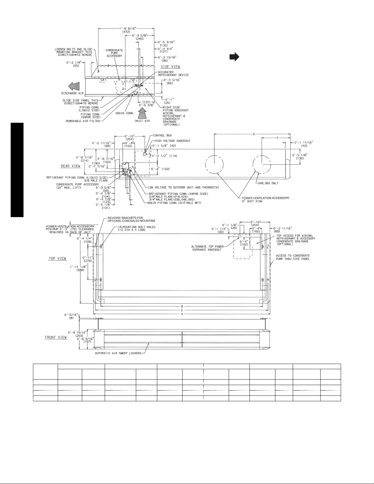
DIMENSIONS -- INDOOR
R
NOTES:
1. Dimensions in [ ] are in millimeters.
2. Direction of airflow.
3. Standard unit clearances are as follows:
• 0 in. on top and rear
• 3in.onleftside
• 12 in. on right side
• 36 in.on bottom
(When facing unit discharge.)
40QAC/38HDR -- 40QAQ/38QR
A08580
UNIT
SIZE
024 108 110 4 --- 2 15/16 1294 3 --- 1 0 1169 4 --- 1 5/8 1260 — — 1 --- 9 5 /8 549
036 117 119 4 --- 1013/16 1493 4 --- 5 7/8 1368 4 --- 9 1/2 1459 — — 2 --- 1 1/2 648
048 149 151 5 --- 119/16 1817 5 --- 6 5/8 1692 5 --- 1 0 1/4 1783 1 --- 9 7/8 555 3 --- 3 1/16 992
060 179 181 7 --- 8 2336 7 --- 3 2211 7 --- 6 5/8 2302 1 --- 1 1 5/8 601 4 --- 1 1 9/16 1512
WEIGHT (lb) A B E F G
Cooling
Only
Heat
Pump
f t --- i n . mm f t --- i n . mm f t --- i n . mm ft --- i n . mm f t --- i n . mm
Fig. 1 -- 40QA Dimensions
2
Page 3
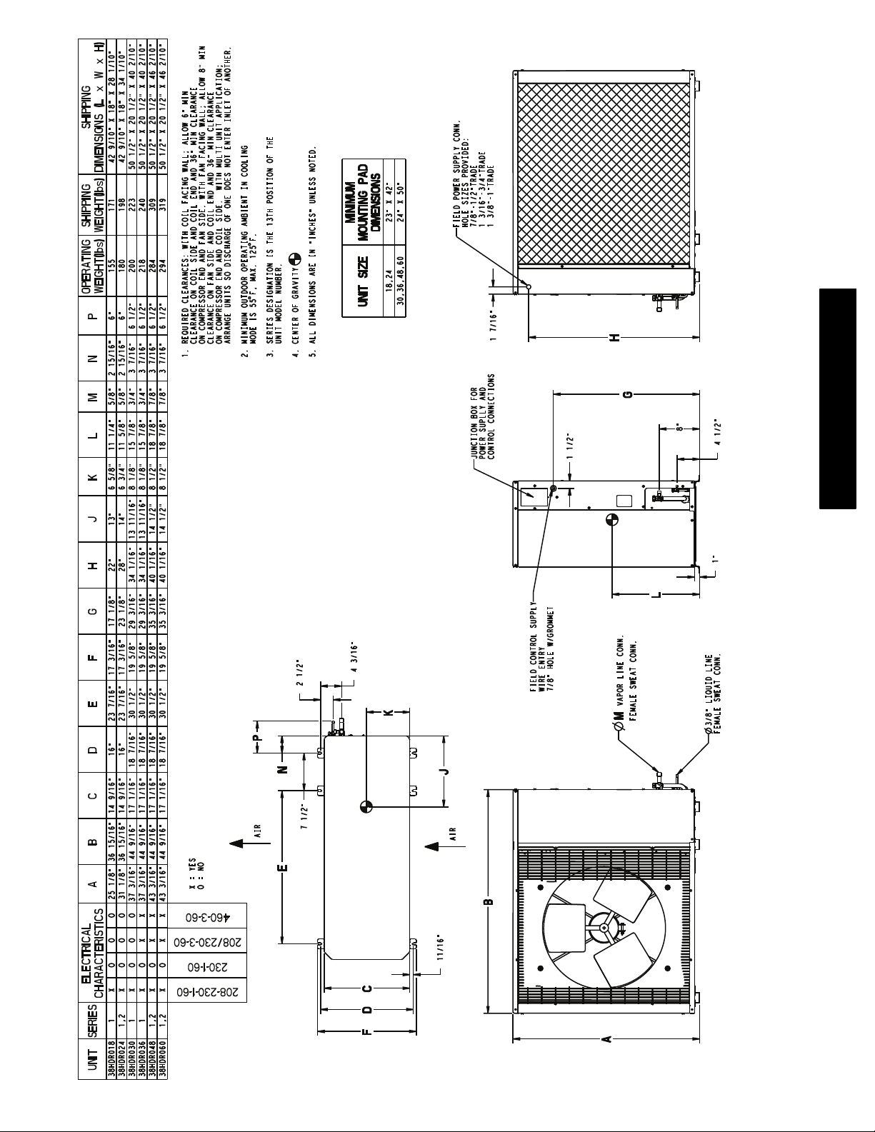
SHIPPING
DIMENSIONS (L x W x H)
SHIPPING
WEIGHT(lbs)
WEIGHT(lbs)
OPERATING
MINIMUM
DIMENSIONS
MOUNTING PAD
F, MAX. 125 F.
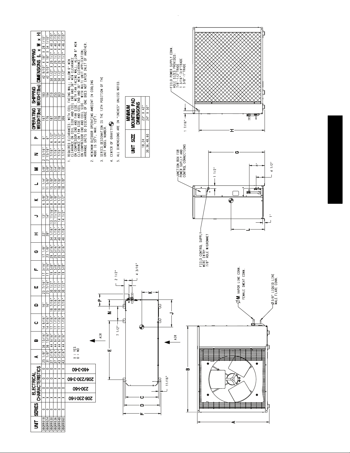
1. REQUIRED CLEARANCES: WITH COIL FACING WALL; ALLOW 6" MIN
CLEARANCE ON COIL SIDE AND COIL END AND 36" MIN CLEARANCE
ON COMPRESSOR END AND FAN SIDE. WITH FAN FACING WALL; ALLOW 8" MIN
CLEARANCE ON FAN SIDE AND COIL END AND 36" MIN CLEARANCE
ON COMPRESSOR END AND COIL SIDE. WITH MULTI UNIT APPLICATION;
ARRANGE UNITS SO DISCHARGE OF ONE DOES NOT ENTER INLET OF ANOTHER.
2. MINIMUM OUTDOOR OPERATING AMBIENT IN COOLING
MODE IS 55
3. SERIES DESIGNATION IS THE 13TH POSITION OF THE
UNIT MODEL NUMBER.
4. CENTER OF GRAVITY
5. ALL DIMENSIONS ARE IN "INCHES" UNLESS NOTED.
18,24 23" X 42"
UNIT SIZE
30,36,48,60 24" X 50"
FIELD POWER SUPPLY CONN.
HOLE SIZES PROVIDED:
7/8"-1/2"TRADE
1 3/16"-3/4"TRADE
1 3/8"-1"TRADE
1 7/16"
JUNCTION BOX FOR
POWER SUPLLY AND
CONTROL CONNECTIONS
1 1/2"
H
G
8"
4 1/2"
40QAC/38HDR -- 40QAQ/38QRR
1"
L
AB C D E F G H J KLMNP
ELECTRICAL
CHARACTERISTICS
UNIT SERIES
38HDR036 1 X O X X 37 3/16" 44 9/16" 17 1/16" 18 7/16" 30 1/2" 19 5/8" 29 3/16" 34 1/16" 13 11/16" 8 1/8" 15 7/8" 3/4" 3 7/16" 6 1/2" 218 240 50 1/2" X 20 1/2" X 40 2/10"
38HDR030 1 X O O O 37 3/16" 44 9/16" 17 1/16" 18 7/16" 30 1/2" 19 5/8" 29 3/16" 34 1/16" 13 11/16" 8 1/8" 15 7/8" 3/4" 3 7/16" 6 1/2" 200 223 50 1/2" X 20 1/2" X 40 2/10"
38HDR024 1,2 X O O O 31 1/8" 36 15/16" 14 9/16" 16" 23 7/16" 17 3/16" 23 1/8" 28" 14" 6 3/4" 11 5/8" 5/8" 2 15/16" 6" 180 198 42 9/10" X 18" X 34 1/10"
38HDR018 1 X O O O 25 1/8" 36 15/16" 14 9/16" 16" 23 7/16" 17 3/16" 17 1/8" 22" 13" 6 5/8" 11 1/4" 5/8" 2 15/16" 6" 155 171 42 9/10" X 18" X 28 1/10"
X = YES
O = NO
38HDR060 1,2 X O X X 43 3/16" 44 9/16" 17 1/16" 18 7/16" 30 1/2" 19 5/8" 35 3/16" 40 1/16" 14 1/2" 8 1/2" 18 7/8" 7/8" 3 7/16" 6 1/2" 294 319 50 1/2" X 20 1/2" X 46 2/10"
38HDR048 1,2 X O X X 43 3/16" 44 9/16" 17 1/16" 18 7/16" 30 1/2" 19 5/8" 35 3/16" 40 1/16" 14 1/2" 8 1/2" 18 7/8" 7/8" 3 7/16" 6 1/2" 284 309 50 1/2" X 20 1/2" X 46 2/10"
P
AIR
460-3-60
208/230-3-60
230-1-60
208-230-1-60
2 1/2"
N
N
7 1/2"
4 3/16"
FIELD CONTROL SUPPLY
WIRE ENTRY
7/8" HOLE W/GROMMET
K
VAPOR LINE CONN.
M
FEMALE SWEAT CONN.
3/8" LIQUID LINE
FEMALE SWEAT CONN.
Fig. 2 -- 38HDR Outdoor Unit Dimensions -- English
J
AIR
E
B
11/16"
C
FD
A
3
Page 4
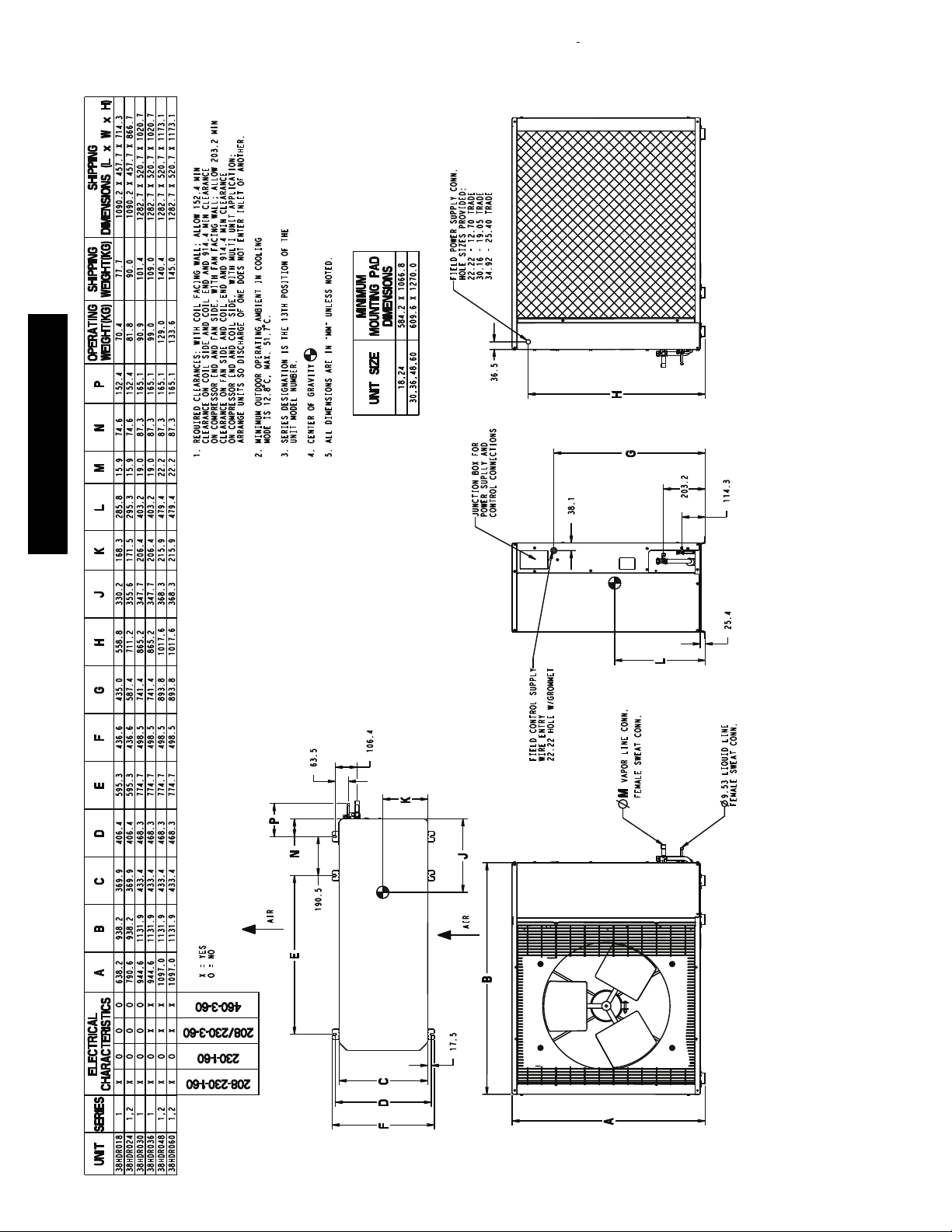
SHIPPING
DIMENSIONS (L x W x H)
SHIPPING
WEIGHT(KG)
WEIGHT(KG)
OPERATING
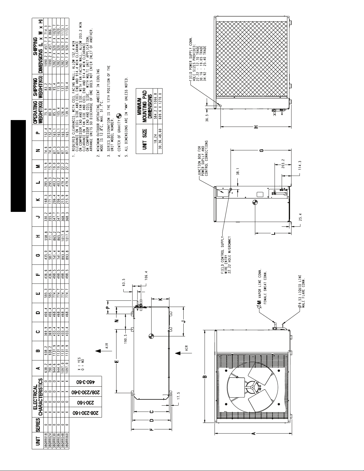
FIELD POWER SUPPLY CONN.
HOLE SIZES PROVIDED:
22.22 - 12.70 TRADE
30.16 - 19.05 TRADE
34.92 - 25.40 TRADE
MINIMUM
DIMENSIONS
MOUNTING PAD
C, MAX. 51.7 C.
18,24 584.2 X 1066.8
UNIT SIZE
30,36,48,60 609.6 X 1270.0
36.5
H
40QAC/38HDR -- 40QAQ/38QRR
3. SERIES DESIGNATION IS THE 13TH POSITION OF THE
UNIT MODEL NUMBER.
4. CENTER OF GRAVITY
1. REQUIRED CLEARANCES: WITH COIL FACING WALL; ALLOW 152.4 MIN
CLEARANCE ON COIL SIDE AND COIL END AND 914.4 MIN CLEARANCE
ON COMPRESSOR END AND FAN SIDE. WITH FAN FACING WALL; ALLOW 203.2 MIN
CLEARANCE ON FAN SIDE AND COIL END AND 914.4 MIN CLEARANCE
ON COMPRESSOR END AND COIL SIDE. WITH MULTI UNIT APPLICATION;
ARRANGE UNITS SO DISCHARGE OF ONE DOES NOT ENTER INLET OF ANOTHER.
2. MINIMUM OUTDOOR OPERATING AMBIENT IN COOLING
MODE IS 12.8
5. ALL DIMENSIONS ARE IN "MM" UNLESS NOTED.
106.4
63.5
K
P
N
JUNCTION BOX FOR
POWER SUPLLY AND
CONTROL CONNECTIONS
J
38.1
FIELD CONTROL SUPPLY
WIRE ENTRY
22.22 HOLE W/GROMMET
G
L
VAPOR LINE CONN.
M
FEMALE SWEAT CONN.
203.2
114.3
25.4
Fig. 3 -- 38HDR Outdoor Unit Dimensions -- SI
9.53 LIQUID LINE
FEMALE SWEAT CONN.
AB C D E F G H J KLMNP
ELECTRICAL
CHARACTERISTICS
UNIT SERIES
38HDR036 1 X O X X 944.6 1131.9 433.4 468.3 774.7 498.5 741.4 865.2 347.7 206.4 403.2 19.0 87.3 165.1 99.0 109.0 1282.7 X 520.7 X 1020.7
38HDR030 1 X O O O 944.6 1131.9 433.4 468.3 774.7 498.5 741.4 865.2 347.7 206.4 403.2 19.0 87.3 165.1 90.9 101.4 1282.7 X 520.7 X 1020.7
38HDR024 1,2 X O O O 790.6 938.2 369.9 406.4 595.3 436.6 587.4 711.2 355.6 171.5 295.3 15.9 74.6 152.4 81.8 90.0 1090.2 X 457.7 X 866.7
38HDR018 1 X O O O 638.2 938.2 369.9 406.4 595.3 436.6 435.0 558.8 330.2 168.3 285.8 15.9 74.6 152.4 70.4 77.7 1090.2 X 457.7 X 714.3
X = YES
O = NO
38HDR060 1,2 X O X X 1097.0 1131.9 433.4 468.3 774.7 498.5 893.8 1017.6 368.3 215.9 479.4 22.2 87.3 165.1 133.6 145.0 1282.7 X 520.7 X 1173.1
38HDR048 1,2 X O X X 1097.0 1131.9 433.4 468.3 774.7 498.5 893.8 1017.6 368.3 215.9 479.4 22.2 87.3 165.1 129.0 140.4 1282.7 X 520.7 X 1173.1
AIR
460-3-60
208/230-3-60
230-1-60
208-230-1-60
190.5
AIR
E
B
17.5
FDC
A
4
Page 5
SHIPPING
DIMENSIONS (L x W x H)
SHIPPING
WEIGHT(lbs)
WEIGHT(lbs)
OPERATING
MINIMUM
DIMENSIONS
MOUNTING PAD
F, MAX. 125 F.
18,24 23" X 42"
30,36,48,60 24" X 50"
UNIT SIZE
3. SERIES DESIGNATION IS THE 13TH POSITION OF THE
UNIT MODEL NUMBER.
4. CENTER OF GRAVITY
1. REQUIRED CLEARANCES: WITH COIL FACING WALL; ALLOW 6" MIN
CLEARANCE ON COIL SIDE AND COIL END AND 36" MIN CLEARANCE
ON COMPRESSOR END AND FAN SIDE. WITH FAN FACING WALL; ALLOW 8" MIN
CLEARANCE ON FAN SIDE AND COIL END AND 36" MIN CLEARANCE
ON COMPRESSOR END AND COIL SIDE. WITH MULTI UNIT APPLICATION;
ARRANGE UNITS SO DISCHARGE OF ONE DOES NOT ENTER INLET OF ANOTHER.
2. MINIMUM OUTDOOR OPERATING AMBIENT IN COOLING
MODE IS 55
5. ALL DIMENSIONS ARE IN "INCHES" UNLESS NOTED.
FIELD POWER SUPPLY CONN.
HOLE SIZES PROVIDED:
7/8"-1/2"TRADE
1 3/16"-3/4"TRADE
1 3/8"-1"TRADE
1 7/16"
JUNCTION BOX FOR
POWER SUPLLY AND
CONTROL CONNECTIONS
1 1/2"
H
G
8"
4 1/2"
40QAC/38HDR -- 40QAQ/38QRR
1"
L
AB C D E F G H J KLMNP
ELECTRICAL
CHARACTERISTICS
UNIT SERIES
38QRR036 0 X O X X 37 3/16" 44 9/16" 17 1/16" 18 7/16" 30 1/2" 19 5/8" 29 3/16" 34 1/16" 13 11/16" 8 1/8" 15 7/8" 3/4" 3 7/16" 6 1/2" 232 255 50 1/2" X 20 1/2" X 40 2/10"
38QRR030 0 X O O O 37 3/16" 44 9/16" 17 1/16" 18 7/16" 30 1/2" 19 5/8" 29 3/16" 34 1/16" 13 11/16" 8 1/8" 15 7/8" 3/4" 3 7/16" 6 1/2" 187 210 50 1/2" X 20 1/2" X 40 2/10"
38QRR024 0 X O O O 31 1/8" 36 15/16" 14 9/16" 16" 23 7/16" 17 3/16" 23 1/8" 28" 14" 6 3/4" 11 5/8" 5/8" 2 15/16" 6" 176 194 42 9/10" X 18" X 34 1/10"
38QRR018 0 X O O O 25 1/8" 36 15/16" 14 9/16" 16" 23 7/16" 17 3/16" 17 1/8" 22" 13" 6 5/8" 11 1/4" 5/8" 2 15/16" 6" 167 183 42 9/10" X 18" X 28 1/10"
X = YES
38QRR060 0 X O X X 43 3/16" 44 9/16" 17 1/16" 18 7/16" 30 1/2" 19 5/8" 35 3/16" 40 1/16" 14 1/2" 8 1/2" 18 7/8" 7/8" 3 7/16" 6 1/2" 306 331 50 1/2" X 20 1/2" X 46 2/10"
38QRR048 0 X O X X 43 3/16" 44 9/16" 17 1/16" 18 7/16" 30 1/2" 19 5/8" 35 3/16" 40 1/16" 14 1/2" 8 1/2" 18 7/8" 7/8" 3 7/16" 6 1/2" 278 303 50 1/2" X 20 1/2" X 46 2/10"
O = NO
P
AIR
460-3-60
208/230-3-60
230-1-60
208-230-1-60
FIELD CONTROL SUPPLY
WIRE ENTRY
7/8" HOLE W/GROMMET
2 1/2"
N
7 1/2"
4 3/16"
K
VAPOR LINE CONN.
M
FEMALE SWEAT CONN.
J
AIR
Fig. 4 -- 38QRR Outdoor Unit Dimensions -- English
3/8" LIQUID LINE
MALE FLARE CONN.
E
B
11/16"
FDC
A
5
Page 6
SHIPPING
DIMENSIONS (L x W x H)
SHIPPING
WEIGHT(KG)
FIELD POWER SUPPLY CONN.
HOLE SIZES PROVIDED:
22.22 - 12.70 TRADE
30.16 - 19.05 TRADE
34.92 - 25.40 TRADE
40QAC/38HDR -- 40QAQ/38QRR
WEIGHT(KG)
OPERATING
355.6 171.5 295.3 15.9 74.6 152.4 80.0 88.2 1090.2 X 457.7 X 866.7
330.2 168.3 285.8 15.9 74.6 152.4 75.9 83.2 1090.2 X 457.7 X 714.3
711.2
558.8
85.0 95.4 1282.7 X 520.7 X 1020.7
139.0 150.4 1282.7 X 520.7 X 1173.1
126.4 137.7 1282.7 X 520.7 X 1173.1
105.4 115.9 1282.7 X 520.7 X 1020.7
165.1
165.1
165.1
87.3 165.1
347.7 206.4 403.2 19.0
741.4 865.2
1. REQUIRED CLEARANCES: WITH COIL FACING WALL; ALLOW 152.4 MIN
CLEARANCE ON COIL SIDE AND COIL END AND 914.4 MIN CLEARANCE
215.9 479.4 22.2 87.3
215.9 479.4 22.2 87.3
347.7 206.4 403.2 19.0 87.3
893.8 1017.6 368.3
893.8 1017.6 368.3
741.4 865.2
MINIMUM
DIMENSIONS
C, MAX. 51.7 C.
ON COMPRESSOR END AND FAN SIDE. WITH FAN FACING WALL; ALLOW 203.2 MIN
CLEARANCE ON FAN SIDE AND COIL END AND 914.4 MIN CLEARANCE
ON COMPRESSOR END AND COIL SIDE. WITH MULTI UNIT APPLICATION;
ARRANGE UNITS SO DISCHARGE OF ONE DOES NOT ENTER INLET OF ANOTHER.
2. MINIMUM OUTDOOR OPERATING AMBIENT IN COOLING
MODE IS 12.8
3. SERIES DESIGNATION IS THE 13TH POSITION OF THE
UNIT MODEL NUMBER.
4. CENTER OF GRAVITY
5. ALL DIMENSIONS ARE IN "MM" UNLESS NOTED.
63.5
MOUNTING PAD
18,24 584.2 X 1066.8
30,36,48,60 609.6 X 1270.0
UNIT SIZE
106.4
36.5
JUNCTION BOX FOR
POWER SUPLLY AND
CONTROL CONNECTIONS
38.1
FIELD CONTROL SUPPLY
WIRE ENTRY
22.22 HOLE W/GROMMET
H
G
203.2
114.3
25.4
L
Fig. 5 -- 38QRR Outdoor Unit Dimensions -- SI
AB C D E F G H J KLMNP
ELECTRICAL
CHARACTERISTICS
UNIT SERIES
38QRR018 0 X O O O 638.2 938.2 369.9 406.4 595.3 436.6 435.0
38QRR024 0 X O O O 790.6 938.2 369.9 406.4 595.3 436.6 587.4
38QRR030 0 X O O O 944.6 1131.9 433.4 468.3 774.7 498.5
38QRR036 0 X O X X 944.6 1131.9 433.4 468.3 774.7 498.5
38QRR048 0 X O X X 1097.0 1131.9 433.4 468.3 774.7 498.5
38QRR060 0 X O X X 1097.0 1131.9 433.4 468.3 774.7 498.5
X = YES
O = NO
AIR
460-3-60
208/230-3-60
230-1-60
208-230-1-60
K
P
N
N
190.5
J
AIR
VAPOR LINE CONN.
M
FEMALE SWEAT CONN.
9.53 LIQUID LINE
MALE FLARE CONN.
E
B
17.5
FDC
A
6
Page 7
These installation instructions cover the installation of the matched
R
systems listed in table 2.
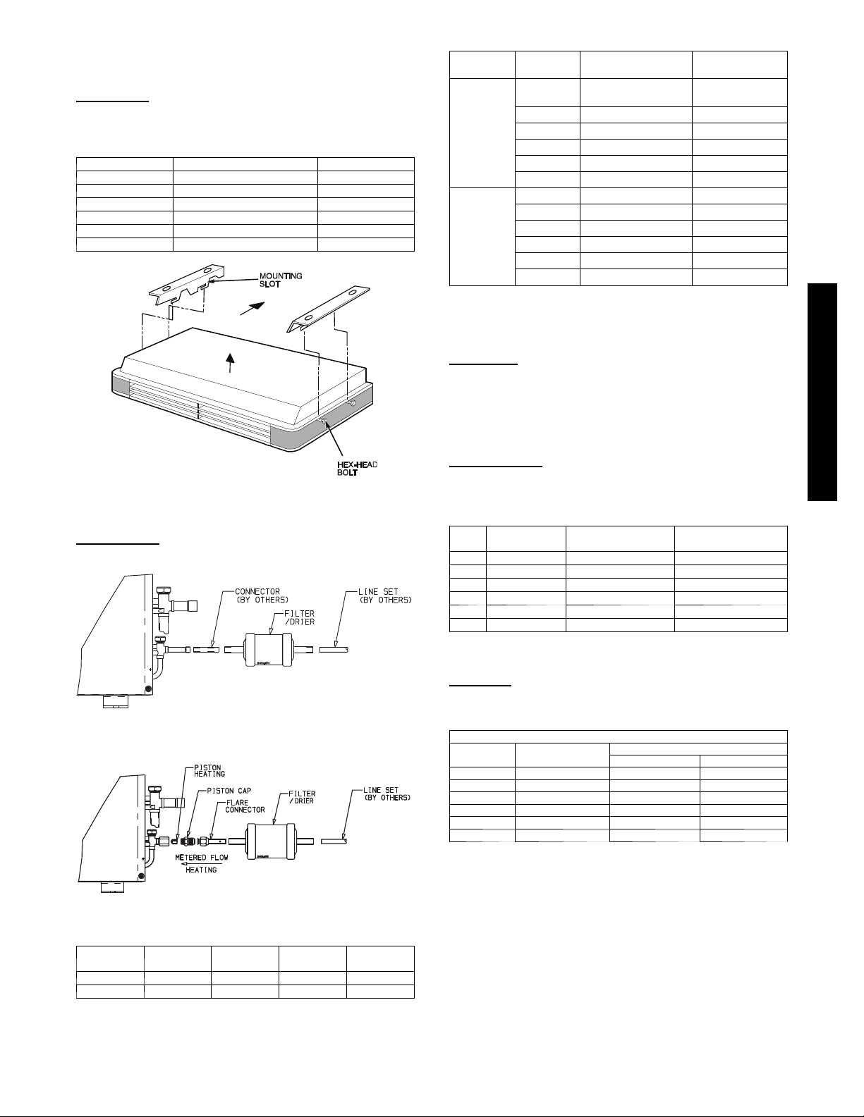
Parts List
Indoor Unit
The following items are included with the indoor unit:
Table 1 – Installation Materials
Part No. Name of Part Qty.
1 Side Panels 2
2 Hex Head Bolts 4
3 Mounting Bracket 2
4 Pistons 1
5 Installation Template 1
6 Adapter Tubes 2
Table 2 – Matched Systems
System
Ty pe
Cooling
Heat Pumps
Heat Pumps
* Units must be configured for 1 --- 1/2 ton operation. Refer to instructions
on page 9.
Nominal
Capacity
018 3 8 H D R 0 1 8 --- --- --- 3
024 3 8 H D R 0 2 4 --- --- --- 3 4 0 Q AC024 --- --- --- 3
030 3 8 H D R 0 3 0 --- --- --- 3 4 0 Q AC036 --- --- --- 3
036 38HDR036 ------ --- 3/5/6 4 0 Q A C 0 3 6 --- --- --- 3
048 38HDR048 ------ --- 3/5/6 4 0 Q A C 0 4 8 --- --- --- 3
060 38HDR060 ------ --- 3/5/6 4 0 Q A C 0 6 0 --- --- --- 3
018 3 8 Q R R 0 1 8 --- --- --- 3 4 0 Q AQ0 2 4 --- --- --- 3
024 3 8 Q R R 0 2 4 --- --- --- 3 4 0 Q AQ0 2 4 --- --- --- 3
030 3 8 Q R R 0 3 0 --- --- --- 3 4 0 Q AQ0 3 6 --- --- --- 3
036 38QRR036 ------ --- 3/5/6 4 0 Q A Q 0 36 --- --- --- 3
048 38QRR048 ------ --- 3/5/6 4 0 Q A Q 0 48 --- --- --- 3
060 38QRR060 ------ --- 3/5/6 4 0 Q A Q 0 60 --- --- --- 3
Outdoor Unit Indoor Unit
4 0 QAC 0 2 4 --- --- --- 3
*
SYSTEM REQUIREMENTS
Clearances
Allow sufficient space around the indoor and outdoor unit for
proper airflow circulation and servicing. Refer to Fig. 1 through
Fig. 5 for minimum required clearances.
Piping: Piping and insulation is field supplied.
Fig. 6 -- Hanging Fan Coil Unit
Outdoor Unit
The following items are included with the outdoor unit:
Fig. 7 -- 38HDR018--036
A09532
A09536
Piping Lengths
The minimum length between the indoor and outdoor units is 10 ft
(3 m). Refer to table 3 for the maximum lengths allowed.
Table 3 – Maximum Refrigerant Line Lengths
Unit
Size
18K 200 (61) 65 (19.8) 200 (61)
24K 200 (61) 65 (19.8) 200 (61)
30K 200 (61) 65 (19.8) 200 (61)
36K 200 (61) 65 (19.8) 200 (61)
48K 200 (61) 65 (19.8) 200 (61)
60K 200 (61) 65 (19.8) 200 (61)
Note: For lengths greater than 25 ft (7.6 m), refer to the Duct Free Long
Max Line
Length ft(m)
Line Guide.
Max Elevation (ID
over OD) ft(m)
Max Elevation (OD
over OD) ft(m)
Pipe Sizes
Refer to table 4 for pipe sizes.
Table4–PipeSizes
PIPE SIZES (in)
Unit Size Liquid Phase
18 3/8 5/8 5/8
24 3/8 5/8 5/8
30 3/8 3/4 3/4
36 3/8 3/4 3/4
48 3/8 7/8 3/4
60 3/8 7/8 3/4
Note: On heat pumps, both lines need to be insulated using at least 1/2 inch
closed foam insulation.
38HDR 38QRR
Vapo r
40QAC/38HDR -- 40QAQ/38QR
A09537
Fig. 8 -- 38QRR018--036
Model Filter Drier
38HDR n --- --- --38QRR n n n n
Piston
Cap
Pistons
Flare
Connector
7
Page 8
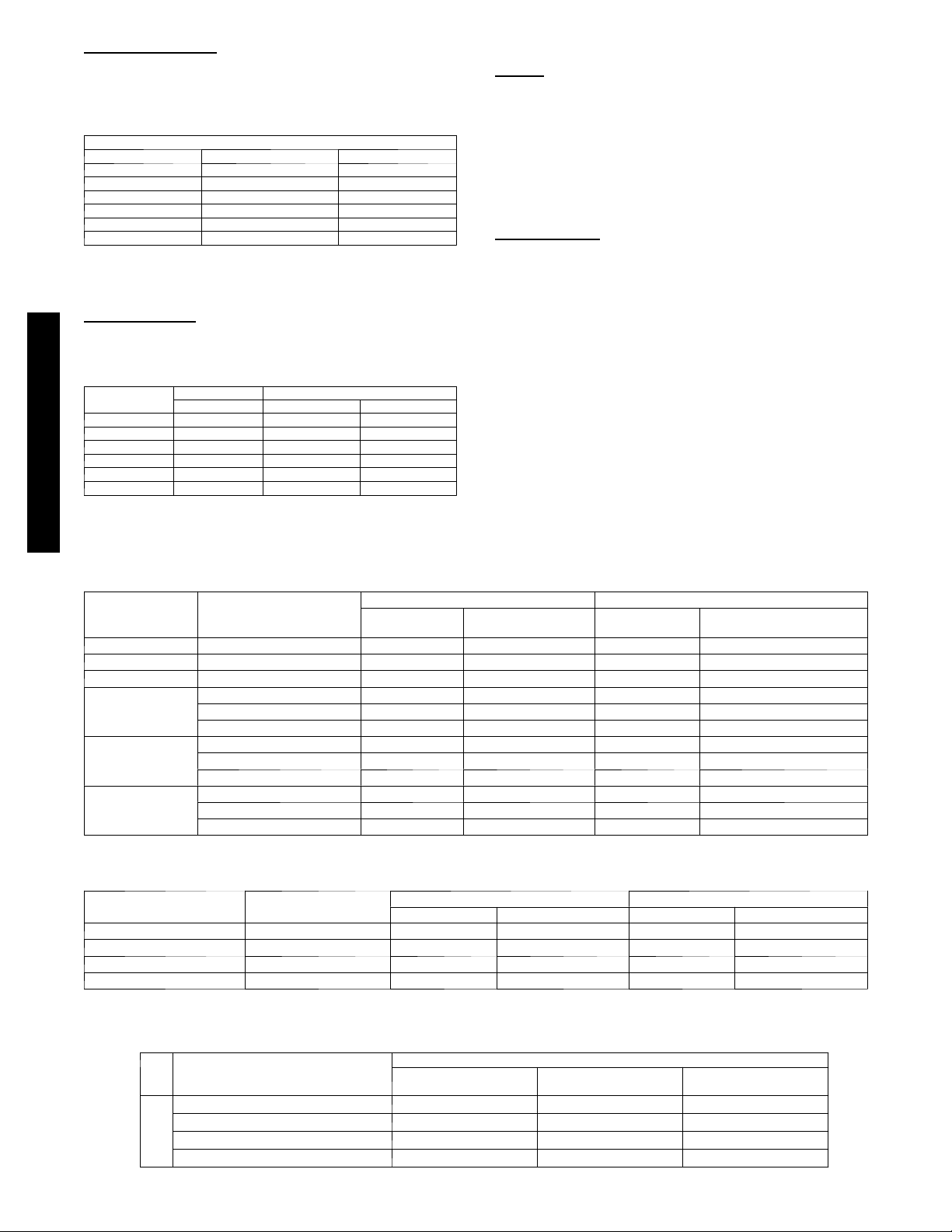
Refrigerant Charge
R
The 38HDR and 38QRR units can be matched with multiple
outdoor units and thus additional charge might be required when
matched with the 40QAC or 40QAQ units.
Table 5 – Additional Charge
Unit Size 38HDR 38QRR
018 0.7 (0.32) 0.7 (0.32)
024 1.3 (0.59) 0.8 (0.36)
030 1.4 (0.64) 0
036 0.2 (0.1) 0.5 (0.23)
048 0.2 (0.1) 0
060 0.5 (0.23) 0
Note: The above additional charge is required amount for line lengths up to
25 ft (7.6 m). For line lengths exceeding 25 ft (7.6 m), additional charge will
be required. Refer to the Duct Free Splits Long Line Guide.
Additional Charge lb. (kg.)
Metering Device
The 40QAC and 40QAQ units use an accurator or a TXV as
shown in Table 6.
Table 6 – Accurator Sizes
Unit Size
018 TVX 49 40
024 TVX 55 43
030 TVX 65 55
036 TVX 70 63
048 TVX 80 73
060 TVX TXV 80
NOTE: Pistons are supplied with either the indoor or outdoor units.
Cooling Only Heat Pumps
40QAC 40QAQ 38QRR
Power and Connecting Cables -- Field Supplied
Power:
S The main power is supplied to both the indoor and outdoor
units.
S Consult local building codes, NEC (National Electric Code) or
CEC (Canadian Electric Code) for any special requirements.
S Use Table 7 for the electrical requirements for the outdoor units
and Table 8 for the indoor units to correctly size the cables and
disconnect switches.
Control Wiring
Thermostat wires should be used for control wiring between the
indoor and outdoor units. A two conductor cable is required for
the cooling only units and a seven conductor cable is required on
heat pumps. 18 AWG is recommended for any length up to 200 ft
(61.0 m).
User Interface -- Finished Goods Accessory
Any of the following three thermostats can be used depending on
the type of system on hand and the desired features. Refer to Table
9 to select the proper thermostat.
40QAC/38HDR -- 40QAQ/38QR
Table 7 – 38HDR / QRR Electrical Requirements
UNIT SIZE V --- P H --- H z
018 208/230 ---1 ---60 12.1 20 12.1 20
024 208/230 ---1 ---60 17.7 25 18.8 30
030 208/230 ---1 ---60 19.1 30 17.5 30
208/230--- 1--- 60 19.1 30 20.9 30
036
048
060
208/230--- 3--- 60 13.0 20 14.1 20
4 6 0 --- 3 --- 6 0 7.9 15 7.9 15
208/230--- 1--- 60 26.4 40 34.6 50
208/230--- 3--- 60 17.9 25 22.4 30
4 6 0 --- 3 --- 6 0 8.4 15 10.0 15
208/230--- 1--- 60 34.5 60 34.5 60
208/230--- 3--- 60 21.5 30 23.6 40
4 6 0 --- 3 --- 6 0 10.6 15 10.6 15
MIN CKT AMPS
Table 8 – 40QAC / QAQ Electrical Requirements
UNIT
024 208/230--- 1 0.63 15.0 9.29 15.0
036 208/230--- 1 1.60 15.0 17.70 20.0
048 208/230--- 1 2.00 15.0 23.80 25.0
060 208/230--- 1 3.30 15.0 28.70 30.0
VOLTAGE
V --- P h --- 6 0 H z
38HDR 38QRR
FUSE/HACR BKR
AMPS
40QAC 40QAQ
MCA MOCP MCA MOCP
MIN CKT AMPS FUSE/HACR BKR AMPS
Table 9 – Thermostat Selection
Model Number
7 Day Programmable
Feature s
5+1+1 Day Programmable --- ---
Remote Room Sensor
Dry Contact Equipped
Cooling Only & HP
53DFS250--- SL
√ √
√ √
√ √
System Type
Cooling Only
53DFS250--- FS
Cooling Only
53DFST2 --- NP
---
√
---
8
Page 9

Operating Range
R
Ensure that the system operates within the application guidelines
shown in the following tables.
Cooling operating range:
Maximum Minimum
DB
_F(_C)WB_F(_C)DB_F(_C)WB_F(_C)
Outdoor Unit
Indoor Unit
125
(51.7)
95
(35)
---
71
(21.7)
55
(12.8)
67
(19.4)
---
57
(13.9)
Heating operating range:
Maximum Minimum
DB
_F(_C)WB_F(_C)DB_F(_C)WB_F(_C)
Outdoor Unit
Indoor Unit
75
(23.9)
80
(26.7)
67
(19.4)
71
(21.7)
--- 2 0
(--- 28.9)
55
(12.8)
---
---
Accessories
An extensive list of field installed accessories is available for both
indoor and outdoor units. Identify what accessories, if any, are
required for the application at hand and consult the separate
installation instructions for the accessories. Some of the
accessories, especially on the indoor units, can be installed much
easier if planned ahead.
INSTALLATION
Complete Pre--installation Checks
1. Unpack Unit -- Store the indoor and outdoor units in the
original packaging until it is moved to the final site for installation.
2. Inspect Shipment -- Upon receipt of shipment, check the
indoor and outdoor units for damage. If there is any damage, forward claim papers directly to the transportation
company. Manufacturer is not responsible for damage incurred in transit.
3. Inspect Parts Supplied With Units – Check all items
against parts list (see page 7). If any items are missing, notify your distributor or Carrier office. To prevent loss or
damage, leave all parts in original packages until installation.
Consider System Requirements
1. Consult local building codes and NEC for special installation requirements.
2. When deciding the location of the indoor and outdoor units,
ensure that the piping run does not exceed the allowed distances listed in Table 3.
3. Make sure the indoor and outdoor units are easily accessible
to electrical power.
4. Allow sufficient clearances for airflow, wiring, refrigerant
piping, and servicing the unit. See Fig.1 through Fig. 5.
5. Condensate piping can be directed through the inside wall
to an approved drain or straight outside.
INSTALL INDOOR UNIT
Plan the installation carefully before you begin.
1. Select indoor unit location. If possible, place the unit adjacent to an outside wall if fresh air is required, and ensure
that the location allows for complete air distribution.
NOTE: If unit is not installed adjacent to an outside
wall and fresh air is required, a power ventilation kit accessory is available.
2. Remove the indoor unit from the carton and place it upside
down and perform the following steps:
a. Remove side panels by sliding forward, then away from
sides of the unit . See Fig. 9.
Fig. 9 -- Removal of Mounting Brackets from Indoor Unit
b. Remove air filters from inlet grilles; then remove and
retain screws securing inlet grilles to indoor unit.
c. Remove inlet grilles from indoor unit by sliding for-
ward.
d. If a size 024 indoor unit is to be matched with a size
018 outdoor unit, switch the Molex plug on the motor.
The Molex plugs are labeled as 018 or 024.
e. Loosen hex bolts on the side of the unit and remove the
mounting brackets by sliding them out in direction
shown in Fig. 10. Allow approximately 3/8 inch space
between the bolt head and the unit as shown in Fig. 10.
Fig. 10 -- Installing Hex--Head Mounting Bolts
in Fan Coil Unit
f. If piping is going to be run from the right hand side,
open knock--out by removing the pre--split portion in
the rear of the right hand side panel with a saw or cutter
knife.
A09525
40QAC/38HDR -- 40QAQ/38QR
A09527
9
Page 10

3. Mount Unit -- the installation location should have already
R
been identified taking into account thepiping length, wiring
and piping,connections, and clearances.
a. Use mounting template, included inside box, to locate
mounting bolt holes, piping holes, electrical connections, and accessory outdoor intake, if used. See Fig. 11
and Fig. 12.
DIMENSIONS in. (cm)
B C
46
(116.8)
53---7/8
(136.8)
66---5/8
(169.2)
87
(221)
49---5/8
(126.0)
57---1/2
(146.1)
70---1/4
(178.4)
90---5/8
(230.2)
A09046
Unit Size
024
036
048
060
50---15/16
(129.4)
58---13/16
(149.4)
71---9/16
(181.8)
(233.7)
DIMENSIONS in. (cm)
A B C
92
46
(116.8)
53---7/8
(136.8)
66---5/8
(169.2)
87
(221)
Fig. 11 -- Fan Coil Unit Hanging Dimensions
49---5/8
(126.0)
57---1/2
(146.1)
70---1/4
(178.4)
90---5/8
(230.2)
A09528
Unit Size
024
036
048
060
* --- Concealed mounting holes
{ --- E x pose d m o u n t i n g h o l e s .
Fig. 12 -- Mounting Included with Fan Coil Unit
NOTE: If fresh air is required, a minimum of 3 inch (76.2 mm)
clearance is required in back of unit.
b. Mount hanging brackets on ceiling (see Fig. 13) for
either concealed or exposed bolt hanging position.
40QAC/38HDR -- 40QAQ/38QR
A09530
Fig. 13 -- Mounting Hanging Brackets
10
Page 11

When mounting brackets, select the proper type of hardware from
R
the guidelines below. See Fig. 14
!
CAUTION
PERSONAL INJURY AND/OR EQUIPMENT
DAMAGE HAZARD
Failure to follow this caution may result in personal injury
and / or equipment damage.
Solid structure in ceiling MUST be used due to weight of the
unit.
Wooden Structure:
Install hanging bolts on a square wooden piece placed over beams.
Newly Built Concrete Slab:
Install hanging bolts with inserts, embedded bolts, etc.
Metal Structure:
Install hanging bolts utilizing an existing angle or by installing a
new support angle.
Previously Built Concrete Slab:
Install hanging bolts with expansion anchor.
Mounting on Ground
1. Mount unit on a solid level concrete pad.
2. If a heat pump is being installed, use a field-- provided snow
stand or ice rack where prolonged subfreezing temperatures
or heavy snow occurs.
3. Position unit so water or ice from roof does not fall directly
onto unit.
4. On cooling only units, an accessory stacking kit can be used
when units are to be stacked. See installation instructions
provided with the accessory kit.
Mounting on Roof
!
CAUTION
PERSONAL INJURY AND/OR EQUIPMENT
DAMAGE HAZARD
Failure to follow this caution may result in personal injury
and / or equipment damage.
Be sure unit panels are securely in place prior to rigging.
1. Rig the unit. Keep the unit upright and lift using a sling.
Use cardboard or padding under the sling, and spreader bars
to prevent sling damage to the unit. See Fig 15. See Fig. 2
through Fig. 5 for center of gravity reference
2. Mount unit on a solid concrete pad or platform.
3. Isolate unit and piping from structure
4. If a heat pump is being installed, use a field-- provided snow
stand or ice rack where prolonged subfreezing temperatures
or heavy snow occurs.
5. On cooling only units, an accessory stacking kit can be used
when units are to be stacked. See installation instructions
provided with accessory kit.
40QAC/38HDR -- 40QAQ/38QR
A09526
Fig. 14 -- Fan Coil Unit Mounting Methods
(hardware is field--supplied)
c. Drill holes for routing refrigerant lines, condensate line
and electrical and control connections.
d. Lift the unit into place, and fit the hex--head bolts on
sides of indoor unit into mounting slots of mounting
brackets. Ensure unit is mounted with a slight tilt to the
rear side for proper drainage.
e. Tighten indoor unit hex--head bolts securely.
INSTALL OUTDOOR UNIT
The outdoor units can be installed on the ground, on the roof, or
mounted on a wall.
NOTE: Install the unit so that the coil does not face into
prevailing winds. If this is not possible and constant wind winds
above 25 mph are expected, use accessory wind baffle. See
installation instructions provided with accessory kit. Wind baffles
should also be used on all units with accessory low ambient
temperature control.
A07396
Fig. 15 -- Lifting Unit with Sling
Mounting Unit on Wall
The units can also be mounted on the wall using the accessory
mounting kit.
11
Page 12

Complete Outdoor Refrigerant Piping Connec-
R
tions
Follow the following general guidelines:
1. Use refrigerant grade field – supplied tubing.
Refer to Table 4 for the correct line sizes.
2. Do not use less than 10 ft (93.05 m) of interconnecting
tubing.
!
UNIT DAMAGE HAZARD
Failure to follow this caution may result in equipment
damage or improper operation.
If any section of pipe is buried, there must be a 6 in. (152.4
mm) vertical rise to the valve connections on the outdoor
unit. If more than the recommended length is buried,
refrigerant may migrate to cooler, buried section during
extended periods of system shutdown. This causes
refrigerant slugging and could possibly damage the
compressor at start--up.
When more than 80 ft (24.4 m) of interconnecting tubing is used,
consult the Duct--Free Split System Long Line Application Guide
for required accessories.
3. On cooling only units, insulate the liquid line. On heat
pumps, insulate both lines. A minimum of 1/2 inch foam
pipe insulation is recommended.
4. Run the refrigerant tubes as directly as possible and avoid
unnecessary turns and bends.
40QAC/38HDR -- 40QAQ/38QR
5. Suspend refrigerant tubes to avoid damage to insulation or
tubes so they do not transmit vibration to the structure.
6. When passing refrigerant tubes through the wall, seal the
opening so rain and insects do not enter the structure. Leave
some slack in refrigerant tubes between structure and outdoor unit to absorb vibration.
NOTE: A fusible plug is located in unit suction line; do not cap
this plug. If local codes require additional safety devices, install as
directed.
CAUTION
Connection at Outdoor Unit
!
UNIT DAMAGE HAZARD
Failure to follow this caution may result in equipment damage
or improper operation.
To prevent damage to unit or service valves observe the
following:
S A brazing shield MUST be used.
S Wrap service valves with wet cloth or use a heat sink
material.
1. Braze the connector tubes (field supplied for the 38HDR
units and factory supplied for the 38QRR units) to the inlet
of the factory supplied filter drier. If a cooling only unit is
being installed move to step 3 (see Fig. 8).
2. Remove the plastic cap from the liquid and suction service
valve on the 38QRR unit and assemble the heating piston
and piston cap supplied with the outdoor unit as shown in
Fig. 16.
CAUTION
NOTE: Teflon Seal must face toward the outdoor heat pump unit.
A09538
Fig. 16 -- AccuRater Metering Device at Service
Valve (Bypass Type Components),
Heat Pump Systems Only
NOTE: The Teflon seal on the piston should point towards the
liquid service valve.
The size of the factory supplied piston might have to
adjusted for long line applications (over 80 ft / 24.4 m).
Refer to the Duct Free Long Line Application Guide
for additional information.
3. On 38HDR units, remove the plastic caps on the liquid and
suction service valves. Braze the completed filter drier assembly (from Step 1) to the liquid service valve. On the
38QRR unit, connect the completed filter drier assembly
(from Step 1) to the piston cap.
4. Braze the field supplied line set to the filter drier assembly
andtothesuctionvalve.
5. Insulate any exposed areas between the filter drier and the
liquid valve.
Complete Outdoor Power and Control Wiring
!
ELECTRICAL SHOCK HAZARD
Failure to follow this warning could result in personal injury or
death.
The unit cabinet must have an uninterrupted or unbroken
ground to minimize personal injury if an electrical fault should
occur. The ground may consist of electrical wire or metal
conduit when installed in accordance with existing electrical
codes.
!
UNIT DAMAGE HAZARD
Failure to follow this caution may result in equipment damage
or improper operation.
Unit failure as a result of operation on improper line voltage or
excessive phase imbalance constitutes abuse and may cause
damage to electrical components. Such operation could void
any applicable Carrier warranty.
WARNING
CAUTION
12
Page 13

!
R
WARNING
ELECTRICAL SHOCK HAZARD
Failure to follow this warning could result in personal injury or
death.
Before performing service or maintenance, be sure indoor unit
main power switch is turned OFF and indoor blower has
stopped.
Lock out and tag switch with suitable warning label.
Power Wiring
1. Mount outdoor power disconnect. The unit is factory wired
for the voltage shown on the unit nameplate. The fused disconnect switch must be provided within sight of the unit,
readily accessible, but out of reach of children. Provisions
for locking the disconnect switch on the OFF (open) position is advisable. The disconnect switch must comply with
NEC and local codes. Protect the unit and wiring using only
the recommended fuse/circuit breaker size. See Table 10..
2. Run power wiring from main box to disconnect per NEC
and local codes.
3. Run power wiring from the disconnect switch to outdoor
unit. Use only minimum 60_C copper conductors between
the disconnect switch and the unit for field power connection.
4. Route the field power wires through the conduit connection
opening in the unit side panel and connect in junction box
as shown in Fig 17. The unit and power wiring must be
grounded.
SINGLE-PHASE
CONN TO
DISCONNECT
PER NEC
THREE-PHASE
CONN TO
DISCONNECT
PER NEC
LEGEND
NEC -- National Electrical Code
-- Splice (field)
Field Wiring
Factory Wiring
GROUND LEAD
GROUND LEAD
GROUNDING LUG
BLK
BLK
SINGLE-PHASE UNIT
BLK
BLU
YEL
GROUNDING LUG
THREE-PHASE UNIT
A08251
Fig. 17 -- Line Power Connections
NOTE: Operating unit on improper line voltage constitutes
abuse and could affect Carrier warranty. DO NOT
install unit
in a system where voltage may fluctuate above or below
permissible limits.
Control Wiring
The control circuit is 24 volts AC (minimum 40VA) supplied from
the indoor unit.
1. Make sure you have enough control wires to cover the distance between the indoor and outdoor unit.
2. Route one end of the control wiring through the opening
provided in the unit side panel and connect to the control
terminal strip using either Fig. 18 for 38HDR units and Fig.
19 for 38QRR units.
40QAC/38HDR -- 40QAQ/38QR
Y1
Fig. 18 -- 38HDR Typical Control Circuit Connections
A09603
Fig. 19 -- 38QRR Typical Control Circuit Connections
A09509
NOTE: Use No. 18 AWG color--coded, insulated (35_C minimum) wire. If the distance between the indoor and outdoor unit is greater than
100 ft. (30.5 m), as measured along the control voltage wires, use No. 16 AWG color--coded wire to avoid excessive voltage drop.
13
Page 14

ELECTRICAL DATA
R
38HDR
UNIT SIZE
018 208/230 ---1--- 60 187 253 9.0 48.0 0.8 0.125 0.09 12.1 20
024 208/230 ---1--- 60 187 253 13.5 58.3 0.8 0.125 0.09 17.7 25
030 208/230 ---1--- 60 187 253 14.1 73.0 1.5 0.25 0.19 19.1 30
036
048
060
38QRR
UNIT SIZE
018 208/230 ---1--- 60 187 253 9.0 48.0 0.8 0.125 0.09 12.1 20
024 208/230 ---1--- 60 187 253 14.4 58.3 0.8 0.125 0.09 18.8 30
030 208/230 ---1--- 60 187 253 12.8 64.0 1.5 0.25 0.19 17.5 30
40QAC/38HDR -- 40QAQ/38QR
036
048
060
V --- P H --- H z
208/230--- 1--- 60 187 253 14.1 77.0 1.5 0.25 0.19 19.1 30
208/230--- 3--- 60 187 253 9.2 71.0 1.5 0.25 0.19 13.0 20
4 6 0 --- 3 --- 6 0 414 506 5.6 38.0 0.8 0.25 0.19 7.9 15
208/230--- 1--- 60 187 253 19.9 109.0 1.5 0.25 0.19 26.4 40
208/230--- 3--- 60 187 253 13.1 83.1 1.5 0.25 0.19 17.9 25
4 6 0 --- 3 --- 6 0 414 506 6.1 41.0 0.8 0.25 0.19 8.9 15
208/230--- 1--- 60 187 253 26.4 134.0 1.5 0.25 0.19 34.5 60
208/230--- 3--- 60 187 253 15.0 110.0 1.5 0.25 0.19 21.5 30
4 6 0 --- 3 --- 6 0 414 506 7.8 52.0 0.8 0.25 0.19 10.6 15
V --- P H --- H z
208/230--- 1--- 60 187 253 15.5 77.0 1.5 0.25 0.19 20.9 30
208/230--- 3--- 60 187 253 10.1 71.0 1.5 0.25 0.19 14.1 20
4 6 0 --- 3 --- 6 0 414 506 5.6 38.0 0.8 0.25 0.19 7.9 15
208/230--- 1--- 60 187 253 26.5 117.0 1.5 0.25 0.19 34.6 50
208/230--- 3--- 60 187 253 16.7 83.1 1.5 0.25 0.19 22.4 30
4 6 0 --- 3 --- 6 0 414 506 7.3 41.0 0.8 0.25 0.19 10.0 15
208/230--- 1--- 60 187 253 26.4 134.0 1.5 0.25 0.19 34.5 60
208/230--- 3--- 60 187 253 17.7 110.0 1.5 0.25 0.19 23.6 40
4 6 0 --- 3 --- 6 0 414 506 7.8 52.0 0.8 0.25 0.19 10.6 15
Table 10 – 38HDR Electrical Data
VOLTAGE RANGE* COMPRESSOR OUTDOOR FAN MOTOR
Min Max RLA LRA FLA NEC Hp kW Out
Table 11 – 38QRR Electrical Data
VOLTAGE
RANGE*
Min Max
COMPRESSOR OUTDOOR FAN MOTOR
RLA LRA FLA NEC Hp kw Out
MIN CKT
AMPS
MIN CKT
AMPS
FUSE/HACR
BKR AMPS
FUSE/HACR BKR
AMPS
Table 12 – 40QAC/QAQ Electrical Data
UNIT
40QAC024 --- 3 208/230--- 1 187 253 0.50 — — 0.63 15.0 0.50 14
40QAC036 --- 3 208/230--- 1 187 253 1.30 — — 1.60 15.0 1.30 14
40QAC048 --- 3 208/230--- 1 187 253 1.60{ — — 2.00 15.0 1.60 14
40QAC060 --- 3 208/230--- 1 187 253 2.60} — — 3.30 15.0 2.60 14
40QAQ024 --- 3 208/230---1 187 253 0.50 2.00 8.66 9.29 15.0 11.29 14
40QAQ036 --- 3 208/230---1 187 253 1.30 3.00 13.00 17.70 20.0 14.30 14
40QAQ048 --- 3 208/230---1 187 253 1.60{ 4.00 17.40 23.80 25.0 19.00 12
40QAQ060 --- 3 208/230---1 187 253 2.60{ 5.00 21.70 28.70 30.0 24.30 10
LEGEND
FLA --- F u l l L o a d A m p s
LRA --- L o c k e d R o t o r A m p s
MCA --- Minimum Circuit Amps
RLA --- RatedLoadAmps
VOLTAGE
V --- P h --- 6 0 H z
VOLTAGE
RANGE*
MIN. MAX. kW FLA MCA MOCP FLA
FAN
FLA
HEATER POWER
NOTES
* Permissible l imits of the voltage range at which the unit will operate
satisfactorily
{ Onefanis1.1amps,thesecondfanis0.5amps.
} Two fans each operating at 1.3 amps.
MINIMUM
WIRE SIZE
(AWG)
14
Page 15

40QAC/38HDR -- 40QAQ/38QR
R
Fig. 20 -- 38HDR and 40QAC Cooling System Wiring Diagram
A09597
15
Page 16

40QAC/38HDR -- 40QAQ/38QR
R
Fig. 21 -- 38QRR and 40QAQ Heat Pump System Wiring Diagram
A09598
16
Page 17

Complete Indoor Piping
R
The piping to the indoor unit can be routed from the back, side and
top. If the unit is being piped from the top or the side see note
below.
1. On heat 40QAQ024 – 048, the cooling piston (indoor) is
shipped in the factory installed metering device with the indoor unit. Use Table 6 to verify that you have the correct
piston size for the system being installed.
2. Run the line set and the control wiring from the outdoor to
the indoor unit through the hole in the wall. Keep the piping
general guidelines in mind.
3. Cut the liquid and suction line to the correct length using a
tube cutter.
4. Remove the flare nuts from the indoor piping connections.
Install them onto the liquid and suction lines and make flare
connections.
5. Apply a small amount of refrigerant oil to the flare connection and tubing.
6. Align the tubing with the refrigerant connections on the indoor unit.
7. Tighten the flare nut and finish the installation using two
wrenches as shown in Fig. 22.
NOTE: When piping is being routed from the top or side, two
pipe adaptors are supplied with the unit. Flare the pipe
adaptors to the indoor unit connections and sweat the other
ends to the line set.
Connect Condensate Drain Line
Observe all local sanitary codes when installing condensate drains.
Refer to Fig. 23 for drain pipe connection from indoor unit.
1. Use hard polyvinyl chloride (PVC) pipe material with nominal ID of 3/4 in. to connect at drain line. Use pipe insulation 1/4 in. thick, such as Armaflex insulation, on exposed
piping inside the conditioned space.
2. To insure regular flow of condensate water, the drain pipe
should be pitched toward an open drain or sump at a downward slope of at least 1/4 in. per ft.
3. If the drain piping is routed through the side of the unit, attach a field fabricated piece of sheet metal to support the
drain pipe as shown in Fig. 23.
4. Attach drain pipe with nylon wire tie passing through hole
as shown in Fig. 23.
A07354
Fig. 22 -- Tighten Flare Nut
8. Insulate both connections on the 38QRR and the liquid line
connection on the 38HDR units.
40QAC/38HDR -- 40QAQ/38QR
(Field Fabricated)
A09534
Fig. 23 -- Routing Drain Piping
NOTE: Do not fasten nylon wire ties tight enough to deform the
insulation, as this affects performance.
5. Install an external trap at the end of the condensate line.
NOTE: Should the installation require one, a condensate pump
may be ordered as a fields--installed accessory. It is easier to install
pump before hanging the unit.
17
Page 18

Complete Control Wiring
*
R
1. Run the control wiring close to the terminal block on the
indoor unit.
2. Connect the wires as shown in Fig 18 and Fig. 20 for
38HDR units, and Fig. 19 and Fig. 21 for 38QRR units.
Complete Power Connection To Indoor Unit
Be sure field wiring complies with local building codes and NEC,
and unit voltage is within limits shown in Table 12.
Contact local power company for correction of improper line
voltage.
!
ELECTRICAL SHOCK HAZARD
Failure to follow this warning could result in personal injury
or death.
Before installing, modifying, or servicing system, main
electrical disconnect switch must be in the OFF position.
There may be more than 1 disconnect switch. Lock out and
tag switch with a suitable warning label.
!
UNIT DAMAGE HAZARD
Failure to follow this caution may result in equipment damage
or improper operation.
Unit failure as a result of operation on improper line voltage or
excessive phase imbalance constitutes abuse and may cause
40QAC/38HDR -- 40QAQ/38QR
damage to electrical components. Such operation could void
any applicable Carrier warranty.
WARNING
CAUTION
2. Route line power leads from inside disconnect to the fan
coil. Place wire through the whole on the control box.
3. Connect wire to high voltage terminal board (TB1) and
ground screw.
NOTE: When routing the wire in the unit, use care to keep the
wire away from refrigerant and condensate piping and any
sharp edges.
NOTE: The 208/230--v units are factory wired for 230--v to
24--v transformer operation, For 208--v to 24--v operation,
interchange the blue (208--v) and red (230--v) wires. Cap any
unused wires with wire nuts.
Install Thermostat
These systems use a three speed thermostat. Refer to Table 9 for a
list of recommended thermostats.
1. Mount thermostat to a wall in the occupied space using
hardware provided with the thermostat. Locate the thermostat, preferably on an interior wall, in an area that is not subjected to drafts or direct sunlight through windows.
2. Run the thermostat wires to the control box of the indoor
unit. If running the thermostat through the back of the unit,
3/8 in. space between the unit and the wall is required.
3. Route wires over refrigerant and drain piping as shown in
Fig. 24.
NOTE: Use copper wire only between disconnect switch(es) and
unit.
NOTE: Install branch circuit disconnect of adequate size to handle
unit starting current per NEC. Locate disconnect within sight of,
and readily accessible from, unit, per section 440--14 of NEC.
Some codes allow indoor unit to share disconnect with outdoor
unit if disconnect can be locked; check local code before installing
in this manner.
1. Route ground and power wires.
!
ELECTRICAL SHOCK HAZARD
Failure to follow this warning could result in personal injury
or death.
According to NEC and most local codes, the unit must have
an uninterrupted, unbroken ground to minimize personal
injury if an electric fault should occur. The ground may
consist of electrical wire or metal conduit when installed in
accordance with existing electrical codes.
WARNING
Field-supplied.
A09533
Fig. 24 -- Routing Wires Over Piping
NOTE: Do not route wires under the piping, or wires could
impede air filter removal.
4. Connect the thermostat wires to the indoor unit per Fig 25
for a 40QAC unit and Fig. 26 for a 40QAQ unit.
18
Page 19

HP ONLY
t
R
COOLING ONLY
Fig. 25 -- Thermostat Wire Connection for 40QAC
Heating Only
A09545
Fig. 26 -- Thermostat Wire Connection for 40QAQ
Reassemble Indoor Unit
1. Reinstall filters and inlet grilles
2. Reinstall the side panels
START--UP
Preliminary Checks
1. Check condensate drainage system; on the opposite side of
the drain connection, insert a water bottle up into the fan
coil unit and fill the drain pan (see Fig. 27). Water must
flow steadily; if not, check the pipe slope or inspect for any
pipe restrictions.
Fig. 27 -- Inserting Water Into Drain Pan
2. Make sure all wiring connections are correct and they are
tight.
3. Field electrical power source must agree with unit name
plate rating.
4. Check that all barriers, covers, and panels are in place. Ensure that the filters and return--air grilles on the indoor unit
have been installed and that the discharge louvers are positioned correctly.
5. All service valves must be closed.
6. On units with crankcase heaters, ensure belly--band heaters
are tight around the compressor.
A09538
Evacuate and Dehydrate the System
!
UNIT DAMAGE HAZARD
Failure to follow this caution may result in equipment damage
or improper operation.
Never use the system compressor as a vacuum pump.
Using Vacuum
1. Completely tighten flare nuts A, B, C, D, connect manifold
gage charge hose to a charge port of the low side service
valve. (See Fig. 28.)
2. Connect charge hose to vacuum pump.
3. Fully open the low side of manifold gage. (See Fig. 29.)
4. Start vacuum pump
5. Evacuate using either deep vacuum or triple evacuation
method.
6. After evacuation is complete, fully close the low side of
manifold gage and stop operation of vacuum pump.
7. The factory charge contained in the outdoor unit is good for
up to 25 ft. (8 m) of line length. For refrigerant lines longer
than 25 ft (8 m), add 0.3 oz. per foot of extra piping up to
the maximum allowable length.
8. Disconnect charge hose from charge connection of the low
side service valve.
9. Fully open service valves B and A.
10. Securely tighten caps of service valves.
Outdoor Unit
Service Valve
CAUTION
Pump
Refrigerant
Low Side
A
High Side
B
Fig. 28 -- Service Valve
Indoor Uni
C
D
A07360
40QAC/38HDR -- 40QAQ/38QR
19
Page 20

Manifold Gage
R
500 microns
Low side valve
Charge hose
High side valve
Charge hose
Vacuum pump
Low side valve
Fig. 29 -- Manifold
Deep Vacuum
Method
The deep vacuum method requires a vacuum pump capable of
pulling a vacuum of 500 microns and a vacuum gage capable of
accurately measuring this vacuum depth. The deep vacuum method
is the most positive way of assuring a system is free of air and
liquid water. (See Fig. 30)
5000
4500
4000
3500
40QAC/38HDR -- 40QAQ/38QR
3000
2500
2000
MICRONS
1500
1000
500
01234567
MINUTES
LEAK IN
SYSTEM
VACUUM TIGHT
TOO WET
TIGHT
DRY SYSTEM
Fig. 30 -- Deep Vacuum Graph
A07361
A95424
Triple Evacuation
Method
The triple evacuation method should only be used when vacuum
pump is only capable of pumping down to 28 in. of mercury
vacuum and system does not contain any liquid water.
Refer to Fig. 31 and proceed as follows:
1. Pump system down to 28 in. of mercury and allow pump to
continue operating for an additional 15 minutes.
2. Close service valves and shut off vacuum pump.
3. Connect a nitrogen cylinder and regulator to system and
open until system pressure is 2 psig.
4. Close service valve and allow system to stand for 1 hr. During this time, dry nitrogen will be able to diffuse throughout
the system absorbing moisture.
5. Repeat this procedure as indicated in Fig. 31. System will
then be free of any contaminants and water vapor.
EVACUATE
BREAK VACUUM WITH DRY NITROGEN
WAIT
EVACUATE
BREAK VACUUM WITH DRY NITROGEN
WAIT
EVACUATE
CHECK FOR TIGHT, DRY SYSTEM
(IF IT HOLDS DEEP VACUUM)
RELEASE CHARGE INTO SYSTEM
A95425
Fig. 31 -- Triple Evacuation Method
To Start the Unit:
1. If the outdoor unit is equipped with a crankcase heater, turn
on the indoor and outdoor disconnect switches to supply
power the system 12 hours before starting the system.
2. Release charge into the system by opening (back--seating)
liquid and suction line service valves.
3. Set the wireless remote control or wired remote control below ambient temperature. Operate the unit for 15 minutes.
4. Refer to Table 5 to determine if additional charge is required. Also, if you have a long line application, refer to the
Duct Free Long Line Application Guide to determine the
additional charge that is required beyond 25 ft (7.6 m).
5. Calculate the total additional charge required and weigh in.
6. Charge should be added as liquid (not gas) slowly and carefully to low side to avoid liquid slugging.
20
Page 21

OPERATING SEQUENCE
R
Ceiling--suspended fan coil units have a relay board which controls
system operation in response to a room thermostat. The user may
manually select any one of 3 fan speeds for unit operation. The
discharge louvers on the unit can be stationary or swing
continuously. A switch located at the bottom of the unit will turn
the swing function on and off.
Ceiling--suspended systems may be equipped with an accessory
power ventilation kit and/or condensate pump.
FAN O PERAT ION — Fan coils are capable of 3--speed
operation. See thermostat instructions for fan speed selection.
When the fan(s) is operating in medium or high speed and the unit
is equipped with the power ventilation kit, the ventilation fan will
operate to provide fresh air.
COOLING MODE OPERATION — When the room thermostat
senses a demand for cooling, the fan coil relay board is energized.
The indoor fan(s) will start in the selected speed (if it is not already
operating). The reversing valve (heat pump only) will energize for
cooling operation.
The internal condensate pump (if so equipped) runs whenever the
reversing valve is energized (heat pump only) and/or the unit is in
cooling. As long as the condensate float switch and freeze
protection thermostat are closed, the cooling relays in the fan coil
unit will close. This energizes the compressor and outdoor fan in
the outdoor unit.
The compressor will continue to operate until the room thermostat
is satisfied. When the cooling demand is satisfied, the compressor
and outdoor fan will stop. If the system is in the AUTO. position,
the indoor fan will stop with the compressor.
If the unit has the accessory ventilation kit, the ventilation fan will
operate whenever the indoor fan is set for medium or high speed.
HEAT PUMP OPERATION — When the room thermostat
senses a demand for heating the indoor fan will start in the selected
speed (if not already operating), and the reversing valve will not be
energized.
The internal condensate pump (if supplied) and freeze protection
thermostat are not operated during heating operation. The control
relay (CR2) closes, and the compressor and outdoor fan are
energized through the defrost board (DFB), which is located in the
outdoor unit. The microprocessor logic in the DFB is energized
when the compressor starts, and the defrost timer runs. Once every
90 minutes (factory default setting) of compressor run time, the
DFB logic checks the defrost thermostat (DFT). If the DFT is
open, the unit continues in heating operation. If the DFT is closed,
the DFB switches the unit to defrost mode. The timing on the DFB
may be set at either 30, 50, or 90 minutes.
DEFROST (Heat Pump Only) — The DFB energizes the RVS
(reversing valve solenoid), and the reversing valve switches to the
cooling position. The K1 relay on the DFB opens and the outdoor
fan stops. The W2 contact on the DFB is also energized, which in
turn energizes the defrost relay on the fan coil relay board, turns off
the electric heater and stops the indoor fan.
The DFB logic checks the 10--minute defrost timer and the DFT. If
the DFT opens in less than 10 minutes, the DFB switches the unit
back to normal heating operation. If the DFT remains closed, the
DFB switches the unit back to heating operation after 10 minutes.
When the DFB changes back to heating mode, the RVR (reversing
valve relay) is de--energized and the reversing valve switches back
to heating operation. Both the outdoor and indoor fans come back
on, and if necessary, the electric heater also turns on. SYSTEM
SAFETIES — The system is equipped with the following safety
devices to protect system components: Indoor coil freeze
protection thermostat — If a coil temperature of 28_F (--2.22_C) or
lower is sensed, the compressor and outdoor fan will be shut down
until the coil temperature exceeds 28_F (--2.22_C). The indoor fan
will continue to run. Condensate float switch (units equipped with
accessory condensate pump, cooling cycle only) — If the level of
condensate in the drain pan rises too high, the condensate float
switch will turn the system off.
CLEANING AND MAINTENANCE
!
ELECTRICAL SHOCK HAZARD
Failure to follow this warning could result in personal
injury or death.
Before installing, modifying, or servicing system, main
electrical disconnect switch must be in the OFF
position. There may be more than 1 disconnect switch.
Lock out and tag switch with a suitable warning label.
!
UNIT DAMAGE HAZARD
Failure to follow this caution may result in equipment
damage or improper operation.
To avoid shrinkage, do not wash filter in water over
120_F (48.9_C). To avoid damage, do not expose filter to
fire or direct sunlight . Clean the filter more frequently
when air is extremely dirty.
For proper system operation, perform the cleaning and
maintenance operations in Table 13.
Lubrication — The indoor--fan, automatic air sweep, and the
outdoor--fan motors are factory lubricated and require no oiling.
AIR FILTERS
!
UNIT DAMAGE HAZARD
Failure to follow this caution may result in equipment
damage or improper operation.
Operating the system with dirty air filters may damage the
indoor unit and can cause reduced cooling performance,
intermittent system operation, frost build--up on the indoor
coil, and blown fuses. Inspect and clean or replace the air
filters monthly.
REMOVE AIR FILTERS — Remove filters by pulling them
straight out.
CLEAN OR REPLACE FILTERS — Filters can be vacuumed
or washed in warm water. Shake filter to remove any excess water,
and replace by sliding filter behind grille until filter snaps in place.
Refer to Fig. 32. If the filter has begun to break down or is torn,
replace it. Replacement filters are available through your dealer.
WARNING
CAUTION
CAUTION
40QAC/38HDR -- 40QAQ/38QR
21
Page 22

Table 13 – Cleaning and Maintenance Schedule
R
TASK MONTHLY QUARTERLY YEARLY
INDOOR UNIT
Clean Air Filters X
Clean Drain Pipe X
Clean Condensate Drain Pan X
Clean Indoor Coil X
Clean Indoor Unit Front Panel X
OUTDOOR UNIT
Clean the Fins From Outside X
Open the Unit and Clean Fins Inside X
Remove Dust From Electrical Parts X
Check Electrical Connections are Tight X
Clean Outdoor Fan X
Clean Outdoor Coil X
Check that Outdoor Fan Assembly is Tight X
Clean Drain Pan X
NOTE: Maintenance procedures for the outdoor units are in the individual unit installation instructions.
CLEAN INDOOR UNIT BOTTOM PANEL — If the bottom
panel of the unit becomes dirty or smudged, wipe the outside of the
panel with a soft dry cloth. Use a mild liquid detergent and wipe
off carefully with a dry cloth.
CLEAN INDOOR COIL — To clean the coil, remove indoor
unit bottom panel and vacuum the coil fins, using care not to bend
or damage fins.
CLEAN OUTDOOR COIL (Outdoor Unit)
!
CAUTION
40QAC/38HDR -- 40QAQ/38QR
CUT HAZARD
Failure to follow this caution may result in personal injury.
Sheet metal parts may have sharp edges or burrs. Use care and
wear appropriate protective clothing and gloves when
cleaning. Clean coil carefully.
To clean the outdoor coil:
1. Remove any dirt or obstruction from discharge opening.
2. Use a garden hose to spray water on the coil. Debris that
collects between coil fins inhibits heat transfer — direct the
water spray between coil fins to flush out debris.
CLEAN CONDENSATE DRAINS — Clean all drains and drain
pans at the start of each cooling season. Check the flow by pouring
water into the drain.
To clean or replace drain pan:
1. Place a plastic sheet on the floor to catch any water that may
spill from drain pan.
2. Remove the intake grille and distribution assembly (attached).
3. Remove the condensate water in the drain pan by letting
water drain into a 3--gallon bucket.
SERVICE
!
ELECTRICAL SHOCK HAZARD
Failure to follow this warning could result in personal injury
or death.
Before servicing system, main electrical disconnect switch
must be in the OFF position. There may be more than 1
disconnect switch. Lock out and tag switch with a suitable
warning label.
!
ENVIRONMENTAL HAZARD
Failure to follow this caution may result in environmental
damage.
Federal regulations require that you do not vent refrigerant to
the atmosphere. Recover during system repair or final unit
disposal.
WARNING
CAUTION
!
UNIT DAMAGE HAZARD
Failure to follow this caution may result in equipment
damage.
Do not use a screwdriver to pry drain pan out of assembly
-- it could damage the pan.
4. Remove the 4 screws holding the drain pan.
5. Carefully hold the drain pan to remove it from the assembly.
CAUTION
A09539
Fig. 32 -- Cleaning Filters
22
Page 23

Before Calling for Service
R
Save the cost of a service call by doing the following:
1. Be sure main power to system is turned on.
2. Press Mode button until OFF is displayed. Wait 5 minutes.
3. Press Mode button until either COOL or HEAT is displayed
(as desired).
4. Adjust thermostat set point to desired room temperature. If
system starts within a few minutes, service may not be necessary. If system does not operate properly, check Table 14
for typical solutions.
IF SYSTEM FAILS TO OPERATE — Be sure:
S unit ON/OFF switch is in ON position
S fuse or circuit breaker is not tripped
FRESH AIR INSTALLATION OPTION
The units have an installation option, which allows for field
installation of fresh air ventilation. Plan the installation carefully.
Before beginning, measure carefully and follow acceptable
building practices, NEC, and local codes.
Ventilation--Air Accessory — Refer to ventilation air accessory
installation instructions.
TROUBLESHOOTING
If the under--ceiling fan coil unit fails to start or operate properly, sometimes the problem is minor and can be handled without a service call.
Refer to Table 14 for some common problems, causes, and typical solutions. See Fig. 36 and 37 for additional system troubleshooting details.
If the problem cannot be corrected, contact a local dealer for further assistance.
Table 14 – Troubleshooting
PROBLEM CAUSE TYPICAL SOLUTION
Blown fuse or circuit breaker tripped at building power
entry.
Indoor and/or outdoor unit disconnect switch is of f. Turn on disconnect switch(es).
Thermostat is set to night mode. Cancel mode using Day/Night button on thermostat.
System Does Not Start.
System Does Not Cool Properly.
System Does not Heat Properly.
Ice or frost has Formed on Indoor
Coil.{
Insufficie nt Airflow.
* If fu se blows or circuit breaker trips again after first start attempt, DO NOT attempt to start system again. Contact your local dealer for assistance.
† When outdoor temperature is approximately 55_F (12.8_C) or below, indoor coil frosting may occur when system is operated in cool ing or maximum
dehumidification mode. Units are not intended to operate below 55_F (12.8_C) without appropriate accessories.
Powe r fa ilu re. Restore power.
Unit is in off mode.
Three--- minute time delay is running. Wait for 3 minutes.
Temperature is above or below the selected temperature.
Air filter(s) in indoor unit is dirty or needs to be replaced. Clean or replace air filter(s).
Tem per atu re is se t t o o h ig h or too low.
Outdoor unit outdoor coil restricted. Remove obstruction.
Fan speed is set too low.
Air filter(s) in indoor unit is dirty or needs to be replaced. Clean or replace air filter(s).
Tem per atu re is se t t o o h ig h or too low.
Outdoor unit outdoor coil restricted. Remove obstruction.
Fan speed is set too low.
Outdoor unit outdoor coil is frosted up.
Low outdoor ---air temperature. Runsysteminfan---onlymodeuntilfrostisgone.
Air filter(s) in indoor unit is dirty or needs to be replaced. Clean or replace air filter(s).
Air filter(s) in indoor unit is dirty or needs to be replaced. Clean or replace air filter(s).
Fan coil unit coil is blocked. Clean air discharge louvers.
Replacefuseorresetcircuitbreaker.*
Press Mode button on thermostat until thermostat displays the desired unit mode.
Select new temperature using the thermostat.
Reset temperature to desired comfort setting using the
thermostat.
Adjust fan speed to high or auto. using the Fan button
on the thermostat.
Reset temperature to desired comfort setting using the
thermostat.
Adjust fan speed to high or auto. using the Fan button
on the thermostat.
Check manual defrost timer setting and adjust as necessary.
40QAC/38HDR -- 40QAQ/38QR
23
Page 24

40QAC/38HDR -- 40QAQ/38QR
R
LEGEND
NC — Normally Closed
ODT — Outdoor Thermostat
NOTE: For systems with indoor units equipped with microprocessor
control, see separate controls, service, and troubleshooting manual.
Fig. 33 -- Troubleshooting the Heating Cycle
A07435
24
Page 25

LEGEND
p
R
NC — Normally Closed
ODT — Outdoor Thermostat
NOTE: For systems with indoor units equipped with microprocessor
control, see se
arate controls, service, and troubleshooting manual.
Fig. 34 -- Troubleshooting the Cooling Cycle
40QAC/38HDR -- 40QAQ/38QR
A07436
25
Page 26

40QAC/38HDR -- 40QAQ/38QR
R
Copyright 2009 Carrier Corp. S 7310 W. Morris St. S Indianapolis, IN 46231 Printed in U.S.A. Edition Date: 10/09
Manufacturer reserves the right to change, at any time, specifications and designs without notice and without obligations.
26
C a t a l o g N o : 4 0 Q A C --- Q --- 2 S I
R e p l a ce s : 4 0 QAC --- Q --- 1 S I
 Loading...