

Page 1

1
50VZ/PZ
38VZ/PZ+40PZ
Vertical Air-Cooled
Split-System Cooling Units
and Heat Pumps
Installation, operation and maintenance instructions
Page 2

2
CONTENTS
START-UP CHECKLIST................................................................................................................................................................. 3
PHYSICAL DATA............................................................................................................................................................................. 4
ELECTRICAL DATA....................................................................................................................................................................... 5
DIMENSIONS ................................................................................................................................................................................... 6
Service area, mm ............................................................................................................................................................................... 13
Centre of gravity, mm........................................................................................................................................................................ 14
Weight distribution, kg ...................................................................................................................................................................... 15
Repositioning unit air discharge........................................................................................................................................................ 16
FAN PERFORMANCE ...................................................................................................................................................................18
SAFETY CONSIDERATIONS ...................................................................................................................................................... 26
INSTALLATION ............................................................................................................................................................................. 26
Siting the unit .................................................................................................................................................................................... 26
Ductwork (indoor air discharge)........................................................................................................................................................ 27
Condensate drainage .......................................................................................................................................................................... 27
ELECTRICAL CONNECTIONS .................................................................................................................................................28
Refrigerant line connections (38VZ/PZ and 40PZ)........................................................................................................................... 29
Refrigerant line selection ................................................................................................................................................................... 29
Sizing .................................................................................................................................................................................................30
REFRIGERANT CHARGE........................................................................................................................................................... 31
START-UP ........................................................................................................................................................................................31
REFRIGERANT SYSTEM DESCRIPTION............................................................................................................................... 31
COMPRESSOR REPLACEMENT .............................................................................................................................................. 31
DESCRIPTION OF UNIT PROTECTION DEVICES ..............................................................................................................32
Operating limits ................................................................................................................................................................................. 32
OPTIONS AND ACCESSORIES .................................................................................................................................................. 32
Hot water heating coil ....................................................................................................................................................................... 32
Electric resistance heaters ..................................................................................................................................................................33
GENERAL MAINTENANCE .......................................................................................................................................................34
SERVICE ......................................................................................................................................................................................... 34
TRANSFORMATION TO SPLIT SYSTEM (50VZ/PZ units) ................................................................................................... 35
FINAL RECOMMENDATIONS ................................................................................................................................................... 35
TROUBLESHOOTING CHART .................................................................................................................................................. 36
Page 3

START-UP CHECK LIST Start up date: ...................................................................
Equipment sold by: ..................................................................................................................................... Contract No: .................................................
Installed by: .................................................................................................................................................. Contract No: .................................................
Site address: .............................................................................................................................................................................................................................
Equipment type and serial No: 50VZ/PZ...........................................................................................................................................................................
38VZ/PZ............................................................................................................................................................................
40PZ..................................................................................................................................................................................
ELECTRICAL DATA:
Supply voltage Ph 1: .
........................ Volts Ph 2: .................... Volts Ph 3 .......................Volts
Nominal voltage:
.............................................. Volts % network voltage: ................................................................................................................
Current draw Ph 1: .................................... Amperes Ph 2: ............................... Amperes Ph 3: .......................................... Amperes
Control circuit voltage:
................................... Volts Control circuit fuse: ........................................................................................ Amperes
Main circuit breaker rating:
............................................................................................................................................................................................................
PHYSICAL DATA:
Outdoor unit : Indoor unit:
Entering air temp.:
................................................................
o
C Entering air temp.: ..............................................................oC
Leaving air temp.:
................................................................
o
C Leaving air temp.: ..............................................................oC
Pressure drop (air):
.............................................................. kPa Pressure drop (air): ............................................................. kPa
Discharge air pressure:
....................................................... Pa Discharge air pressure: ...................................................... Pa
Fan motor input: Ph. 1:
........................................... Volts Fan motor input: Ph. 1: .......................................... Volts
Ph. 2:
........................................... Volts Ph. 2: .......................................... Volts
Ph. 3:
........................................... Volts Ph. 3: .......................................... Volts
SAFETY DEVICE SETTING:
High pressure switch: cut-out: ............................................. kPa cut-in: ............................................................... kPa
Low pressure switch: cut-out:
............................................. kPa cut-in: ................................................................. kPa
Step controller: cut-out 1st step:
...............................
o
C cut-in 1st step: .................................................. oC
cut-out 2nd step:
..............................
o
C cut-in 2 nd step: ...............................................
o
C
Oil level:
.............................................................................................................................................................................................................................................
Oil visible in sight glass? .................................................................................................................................................................................................................
ACCESSORIES:
Commissioning engineer (name):
.................................................................................................................................................................................................
Customer agreement
Name:
.......................................................................................... Date: ......................................................................................................................
Remarks:
Note: Complete this start-up list at the time of installation
3
Page 4

4
Table 1 - Physical data
50VZ (40PZ/38VZ) 015 025 030 031 040 045 055 065 075
Nom. cooling capacity* kW 14.60 22.74 29.75 27.80 35.05 45.21 53.90 63.89 74.35
Unit weight kg
50VZ 230 390 402 410 618 842 894 943 1033
40PZ 78 140 150 150 230 297 317 335 365
38VZ 152 250 252 260 388 545 577 608 668
Compressor Hermetic reciprocating Scroll
Oil charge l 1.8 3.9 3.9 1.8 x 2 4 x 2 4 x 2 4 x 2 4 x 2 6.6 x 2
Oil type Maneurop 160PZ Mobil EAL Arctic 22CC Maneurop 160SZ
Refrigerant R-407C
Refrigerant charge** kg 3.80 6.62 7.43 3.80 x 2 4.70 x 2 6.70 x 2 8.80 x 2 9.40 x 2 11.0 x 2
Evaporator section (40PZ) Copper tubes, aluminium fins
Face area m
2
0.34 0.64 0.69 0.69 0.84 1.10 1.10 1.34 1.34
Rows...fins/m 3...551 4...472 4...472 4...472 4...472 4...551 6...472 6...551 6...551
Test pressure bar 30 30 30 30 30 30 30 30 30
Condenser section (38VZ) Copper tubes, aluminium fins
Face area m
2
0.49 0.87 0.87 0.87 1.19 1.73 1.73 2.12 2.12
Rows...fins/m 5...551 4...551 5...551 5...551 5...551 5...551 6...551 6…551 6...551
Test pressure bar 30 30 30 30 30 30 30 30 30
Evaporator fan (40PZ) Double inlet centrifugal type
Quantity 1 2 2 2 2 2 2 2 2
Nominal air flow l/s 960 1490 1690 1690 2190 2640 2910 3140 3530
Air flow range l/s 768-1152 1192-1788 1352-2028 1352-2028 1752-2628 2112-3168 2328-3492 2512-3768 2824-4236
Nominal static pressure (dry/wet) Pa 90/70 90/70 120/100 120/100 140/120 170/150 180/160 200/180 210/180
Condenser fan (38VZ) Double inlet centrifugal type
Quantity 1 2 2 2 2 2 2 2 2
Nominal air flow l/s 1470 3020 2780 2780 3610 4580 5080 6030 6890
Air flow range l/s 1176-1764 2416-3624 2224-3336 2224-3336 2888-4332 3664-5496 4064-6096 4824-7236 5512-8268
Nominal static pressure Pa 50 50 60 60 60 75 100 100 100
Air filter Filter class M1
Quantity 1 2 2 2 2 3 3 3 3
Width x height mm 800x443 596x540 596x590 596x590 716x590 676x587 616x587 749x587 749x587
Thickness mm 15 15 15 15 15 15 15 15 15
Condensing unit 38VZ*** 015 025 030 031 040 045 055 065 075
Nom. cooling capacity kW 13.47 19.97 27.02 24.80 32.54 40.30 48.21 59.13 71.10
* Based on an outdoor air temperature of 35°C db and an indoor air temperature of 19°C wb
** The refrigerant charge given is for the complete system, but excludes the connection lines.
*** Based on an outdoor air dry bulb temperature of 35°C and a dewpoint suction temperature of 7°C.
50PZ (40PZ/38PZ) 015 025 030 031 040 045 055 065 075
Nom. cooling capacity* kW 13.42 21.81 28.50 27.70 34.36 43.60 52.51 61.94 72.58
Nom. heating capacity** kW 15.76 25.02 30.58 30.20 39.15 50.18 57.43 66.60 83.06
Unit weight kg
50PZ 238 400 412 427 638 864 919 968 1058
40PZ 78 140 150 150 230 297 317 335 365
38PZ 160 260 262 277 408 567 602 633 693
Compressor Hermetic reciprocating Scroll
Oil charge l 1.8 3.9 3.9 1.8 x 2 4 x 2 4 x 2 4 x 2 4 x 2 6.6 x 2
Oil type Maneurop 160PZ Mobil EAL Arctic 22CC Maneurop 160SZ
Refrigerant R-407C
Refrigerant charge*** kg 4.02 7.20 7.71 3.94 x 2 5.40 x 2 7.50 x 2 9.20 x 2 9.50 x 2 11.20 x 2
Indoor section (40PZ) Copper tubes, aluminium fins
Face area m
2
0.34 0.64 0.69 0.69 0.84 1.10 1.10 1.34 1.34
Rows...fins/m 3...551 4...472 4...472 4...472 4...472 4...551 6...472 6...551 6...551
Test pressure bar 30 30 30 30 30 30 30 30 30
Outdoor section (38PZ) Copper tubes, aluminium fins
Face area m
2
0.49 0.87 0.87 0.87 1.19 1.73 1.73 2.12 2.12
Rows...fins/m 5...551 4...551 5...551 5...551 5...551 5...551 6...551 6…551 6...551
Test pressure bar 30 30 30 30 30 30 30 30 30
Indoor fan (40PZ) Double inlet centrifugal type
Quantity 1 2 2 2 2 2 2 2 2
Nominal air flow l/s 960 1490 1690 1690 2190 2640 2910 3140 3530
Air flow range l/s 768-1152 1192-1788 1352-2028 1352-2028 1752-2628 2112-3168 2328-3492 2512-3768 2824-4236
Nominal static pressure (dry/wet) Pa 90/70 90/70 120/100 120/100 140/120 170/150 180/160 200/180 210/180
Outdoor fan (38PZ) Double inlet centrifugal type
Quantity 1 2 2 2 2 2 2 2 2
Nominal air flow l/s 1470 3020 2780 2780 3610 4580 5080 6030 6890
Air flow range l/s 1176-1764 2416-3624 2224-3336 2224-3336 2888-4332 3664-5496 4064-6096 4824-7236 5512-8268
Nominal static pressure Pa 50 50 60 60 60 75 100 100 100
Air filter Filter class M1
Quantity 1 2 2 2 2 3 3 3 3
Width x height mm 800x443 596x540 596x590 596x590 716x590 676x587 616x587 749x587 749x587
Thickness mm 15 15 15 15 15 15 15 15 15
* Based on an outdoor air temperature of 35°C db and an indoor air temperature of 19°C wb
** Based on an outdoor air temperature of 6°C wb and an indoor air temperature of 20°C db.
*** The refrigerant charge given is for the complete system, but excludes the connection lines.
Page 5

5
Table 2 - Electrical data
50VZ (40PZ/38VZ) 015 025 030 031 040 045 055 065 075
Nominal voltage ±10%* V 230 400 230 400 230 400 230 400 230 400 230 400 230 400 230 400 230 400
Nominal power input** kW 7.3 7.3 11.1 11.1 14.0 14.0 14.6 14.6 18.1 18.1 21.4 21.4 25.4 25.4 30.0 30.0 37.6 37.6
Nominal current drawn** A 23.8 13.8 33.1 19.1 39.4 22.8 44.9 26.0 52.6 30.4 64.9 37.5 74.3 43.0 87.8 50.8 122.1 67.1
Effective power input kW 6.8 6.8 10.2 10.2 13.0 13.0 13.6 13.6 16.8 16.8 19.0 19.0 22.2 22.2 26.1 26.1 33.1 33.1
Effective current drawn A 21.6 12.5 30.5 17.6 37.0 21.4 41.9 24.2 56.5 32.6 57.9 33.4 70.0 40.5 76.6 44.3 102.0 59.0
Starting current A 139.5 80.0 174.1 106.3 219.0 133.3 165.9 95.3 235.2 134.0 278.4 156.7 329.1 187.8 384.5 219.0 450.1 256.0
Maximum power input*** kW 7.9 7.9 12.2 12.2 15.5 15.5 16.1 16.1 21.8 21.8 25.2 25.2 29.6 29.6 35.0 35.0 44.2 44.2
Maximum current drawn*** A 24.2 14.0 35.5 20.5 43.2 25.0 49.5 28.6 66.6 38.5 73.1 42.2 88.8 51.3 99.7 57.6 129.5 74.8
Condensing unit 38VZ 015 025 030 031 040 045 055 065 075
Nominal voltage ±10%* V 230 400 230 400 230 400 230 400 230 400 230 400 230 400 230 400 230 400
Nominal power input
+
kW 6.5 6.5 10.1 10.1 12.8 12.8 13.2 13.2 16.7 16.7 19.4 19.4 23.0 23.0 26.9 26.9 34.7 34.7
Nominal current drawn+A 20.6 11.9 29.9 17.3 36.6 21.2 37.8 21.9 56.2 32.5 59.4 34.3 72.7 42.0 79.1 45.7 106.6 61.6
Effective power input kW 6.3 6.3 9.6 9.6 12.3 12.3 12.7 12.7 16.0 16.0 18.3 18.3 21.4 21.4 25.0 25.0 32.5 32.5
Effective current drawn A 20.1 11.6 28.5 16.5 35.4 20.4 36.4 21.1 54.0 31.2 56.0 32.4 67.6 39.1 73.5 42.5 99.9 57.7
Starting current A 136.7 78.4 170.1 104.0 214.1 130.5 161.1 92.5 226.9 129.2 270.9 151.2 319.2 180.9 372.2 211.9 434.2 246.8
Maximum power input++kW 7.7 7.7 11.5 11.5 14.9 14.9 15.3 15.3 20.6 20.6 24.0 24.0 29.1 29.1 33.8 33.8 43.9 43.9
Maximum current drawn++A 23.5 13.6 33.5 19.4 41.4 23.9 42.5 24.5 62.9 36.4 69.4 40.1 87.4 50.5 96.2 55.6 128.5 74.3
* All units are built for 3-phase, 50 Hz supply.
** Based on an outdoor air dry bulb temperature of 35°C and an indoor air wet bulb temperature of 19°C.
*** Based on an outdoor air dry bulb temperature of 46°C and an indoor air wet bulb temperature of 21°C.
+
Based on an outdoor air dry bulb temperature of 35°C and a dewpoint suction temperature of 7°C.
++
Based on an outdoor air dry bulb temperature of 46°C and a dewpoint suction temperature of 12°C.
50PZ (40PZ/38PZ) 015 025 030 031 040 045 055 065 075
Nominal voltage ±10%* V 230 400 230 400 230 400 230 400 230 400 230 400 230 400 230 400 230 400
Nominal power input kW
Cooling** 7.2 7.2 11.2 11.2 13.6 13.6 14.6 14.6 18.1 18.1 21.6 21.6 25.4 25.4 30.2 30.2 38.5 38.5
Heating*** 6.6 6.6 11.1 11.1 12.4 12.4 12.7 12.7 17.5 17.5 20.8 20.8 23.7 23.7 27.1 27.1 34.3 34.3
Nominal current drawn A
Cooling** 23.7 13.7 33.2 19.2 38.4 22.2 46.0 26.6 55.0 31.8 66.1 38.2 73.3 42.4 88.0 50.9 118.5 68.6
Heating*** 22.5 13.0 33.2 19.2 35.8 20.7 41.5 24.0 52.2 30.2 63.7 36.8 70.7 40.9 82.0 47.4 109.8 63.5
Effective power input kW
Cooling 6.7 6.7 10.3 10.3 12.5 12.5 13.6 13.6 16.8 16.8 19.1 19.1 22.2 22.2 26.3 26.3 34.1 34.1
Heating 6.1 6.1 10.3 10.3 11.4 11.4 11.6 11.6 16.2 16.2 18.4 18.4 20.5 20.5 23.2 23.2 29.8 29.8
Effective current drawn A
Cooling 22.1 12.7 30.5 17.7 35.3 20.4 42.8 24.8 51.0 29.5 59.4 33.8 64.1 37.1 76.6 44.3 105.0 60.8
Heating 20.8 12.0 30.8 17.8 32.9 19.0 37.9 21.9 48.3 28.0 56.4 32.6 61.2 35.4 70.2 40.6 95.4 55.2
Starting current A 139.5 80.0 174.1 106.3 219.0 133.3 165.9 95.3 235.2 134.0 278.4 156.7 329.1 187.8 384.5 219.0 450.1 256.0
Maximum power input kW
Cooling
+
8.0 8.0 12.4 12.4 15.2 15.2 16.3 16.3 21.6 21.6 25.3 25.3 30.4 30.4 34.9 34.9 44.5 44.5
Heating
++
7.5 7.5 13.1 13.1 15.8 15.8 14.4 14.4 20.3 20.3 23.7 23.7 28.1 28.1 32.8 32.8 41.6 41.6
Maximum current drawn A
Cooling
+
26.3 15.2 36.8 21.3 42.9 24.8 51.4 29.7 65.6 37.9 77.4 44.7 87.7 50.7 101.7 58.8 137.0 79.3
Heating
++
25.6 14.8 39.2 22.7 45.6 26.4 47.1 27.2 60.6 35.0 72.6 41.9 83.8 48.5 99.2 57.4 133.2 77.0
* All units are built for 3-phase, 50 Hz supply.
** Based on an outdoor air dry bulb temperature of 35°C and an indoor air wet bulb temperature of 19°C.
*** Based on an outdoor air wet bulb temperature of 6°C and an indoor air dry bulb temperature of 21°C.
+
Based on an outdoor air dry bulb temperature of 46°C and an indoor air wet bulb temperature of 21°C.
++
Based on an outdoor air dry bulb temperature of 18°C.
Effective power input in accordance with EUROVENT.
Page 6

6
Fig. 1 - Dimensions, mm
50VZ/PZ 015
38VZ/PZ 015
Optional discharge
40PZ 015
Optional
discharge
Power connection
Drain 3/4" gas
Cable inlet
Optional discharge
Transport skid
Drain
Cable inlet
Transport skid
Transport skid
When designing an installation, always use up-to-date drawings, available from your local Carrier office
Page 7

7
Fig. 2 - Dimensions, mm
50VZ/PZ 025
38VZ/PZ 025 Optional discharge
40PZ 025
Optional discharge
Power connection
Optional
discharge
Drain 3/4" gas
Cable inlet
Transport skid
Drain
Cable inlet
When designing an installation, always use up-to-date drawings, available from your local Carrier office
Transport skid
Transport skid
Page 8

8
Fig. 3 - Dimensions, mm
50VZ/PZ 030
Optional discharge
38VZ/PZ 030
Optional discharge
40PZ 030
Optional discharge
Power connection
Drain 3/4" gas
Cable inlet
Transport skid
Drain
Cable inlet
When designing an installation, always use up-to-date drawings, available from your local Carrier office
Transport skid
Transport skid
Page 9

9
Fig. 4 - Dimensions, mm
50VZ/PZ 031
38VZ/PZ 031
Optional discharge
40PZ 031
Optional
discharge
Power connection
Drain 3/4" gas
Cable inlet
Optional discharge
Transport skid
Drain
Cable inlet
When designing an installation, always use up-to-date drawings, available from your local Carrier office
Transport skid
Transport skid
Page 10

10
Fig. 5 - Dimensions, mm
50VZ/PZ 040
Optional
discharge
38VZ/PZ 040
Optional discharge
40PZ 040
Optional discharge
Power connection
Cable inlet
Drain 3/4" gas
Cable inlet
Drain
Transport skid
When designing an installation, always use up-to-date drawings, available from your local Carrier office
Transport skid
Transport skid
Page 11

11
Fig. 6 - Dimensions, mm
50VZ/PZ 045-055
Optional
discharge
38VZ/PZ 045-055
Optional discharge
40PZ 045-055
Optional discharge
Power connection
Cable inlet
Drain 3/4" gas
Cable inlet
Drain
Transport skid
When designing an installation, always use up-to-date drawings, available from your local Carrier office
Transport skid
Transport skid
Page 12
12
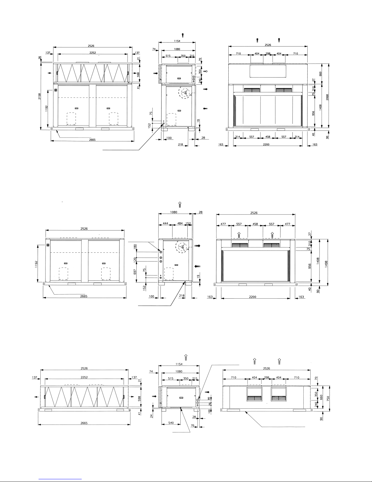
Fig. 7 - Dimensions, mm
50VZ/PZ 065-075
Optional
discharge
38VZ/PZ 065-075
Optional discharge
40PZ 065-075
Optional discharge
Power connection
Cable inlet
Drain 3/4" gas
Cable inlet
Drain
Transport skid
When designing an installation, always use up-to-date drawings, available from your local Carrier office
Transport skid
Transport skid
Page 13
13
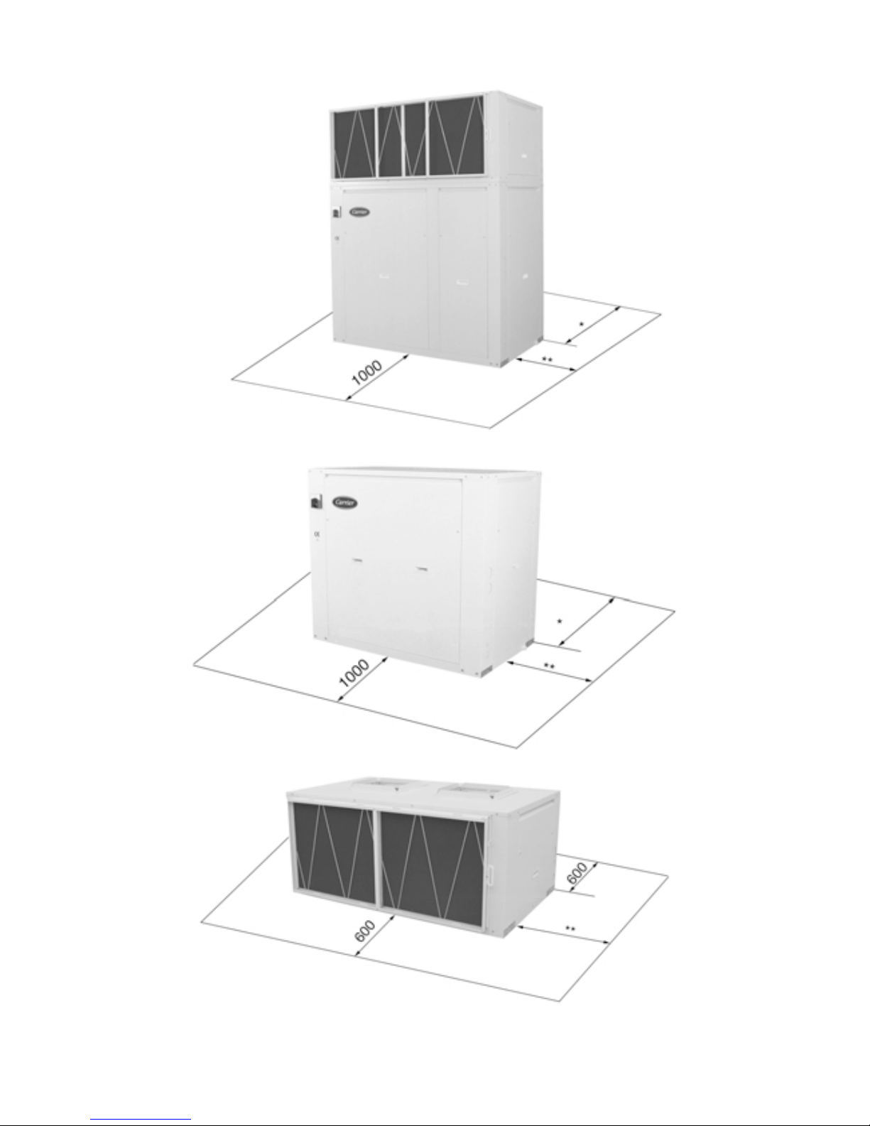
Fig. 8 - Service area, mm
50VZ/PZ
* Service space behind the unit depends on whether or not the unit is installed with outdoor air ducts. It is also necessary to leave space for cleaning and inspection of the outdoor heat
exchanger.
** Space for removal of the air filter and the indoor or outdoor section belt and pulley transmission is required on the right and left hand side.
38VZ/PZ
40PZ
Page 14
Fig. 9 - Centre of gravity, mm (approx.)
50VZ/PZ (all sizes)
Fig. 10 - Centre of gravity, mm (approx.)
38VZ/PZ (all sizes)
Fig. 11 - Centre of gravity, mm (approx.)
40PZ (all sizes)
50VZ/PZ 015 025 030 031 040 045 055 065 075
XG 381 6 27 639 7 23 858 1116 1122 1324 1359
YG 583 772 758 743 703 755 773 767 781
ZG 526 434 448 444 450 525 527 521 527
Measured from point
38VZ/PZ 015 025 030 031 040 045 055 065 075
XG 349 583 595 707 831 1081 1085 1289 1313
YG 382 552 518 509 498 512 509 495 489
ZG 586 479 493 485 463 542 556 566 577
Measured from point
40PZ 015 025 030 031 040 045 055 065 075
XG 499 771 776 776 982 1261 1257 1453 1510
YG 230 296 314 314 308 341 338 337 333
ZG 301 286 307 307 389 452 417 360 364
Measured from point
11
11
1
11
11
1
11
11
1
▲
X
▲
Y
▲
Z
▲
Z
X
▲
▲
Y
Page 15
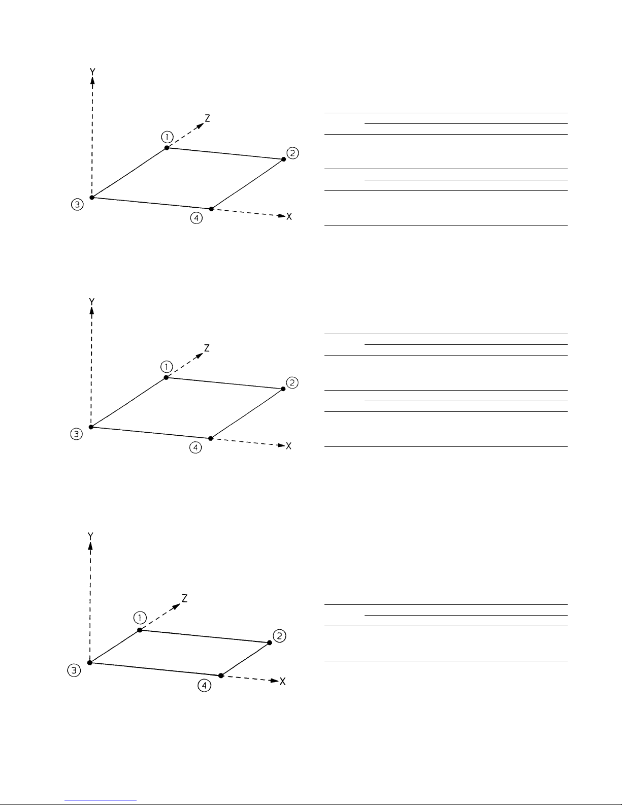
Fig. 12 - Weight distribution, kg (approx.)
50VZ/PZ (all sizes)
Fig. 13 - Weight distribution, kg (approx.)
38VZ/PZ (all sizes)
Control box
Control box
Support 50VZ
points 015 025 030 031 040 045 055 065 075
45 70 68 106 164 178 190 215 235
81 106 127 125 178 267 281 276 302
37 84 72 82 132 158 171 198 217
67 130 135 97 144 239 252 254 279
Support 50PZ
points 015 025 030 031 040 045 055 065 075
47 72 70 110 169 184 196 221 241
83 109 130 129 183 272 287 282 308
39 86 74 87 137 164 178 205 224
69 133 138 101 149 244 258 260 285
Support 38VZ
points 015 025 030 031 040 045 055 065 075
38 62 63 66 115 131 134 151 166
49 82 80 81 128 146 151 164 180
35 58 59 60 83 136 154 152 167
30 48 50 53 62 132 138 141 155
Support 38PZ
points 015 025 030 031 040 045 055 065 075
40 64 65 70 120 136 141 157 172
51 84 82 85 133 151 157 170 186
37 61 62 64 88 142 160 158 173
32 51 53 58 67 138 144 148 162
Fig. 14 - Weight distribution, kg (approx.)
40PZ (all sizes)
Air filters
Support 40PZ
points 015 025 030 031 040 045 055 065 075
14 32 35 35 54 45 50 56 64
27 34 36 36 55 48 54 55 63
14 36 39 39 59 103 107 113 120
23 38 40 40 62 101 106 111 118
Page 16

16
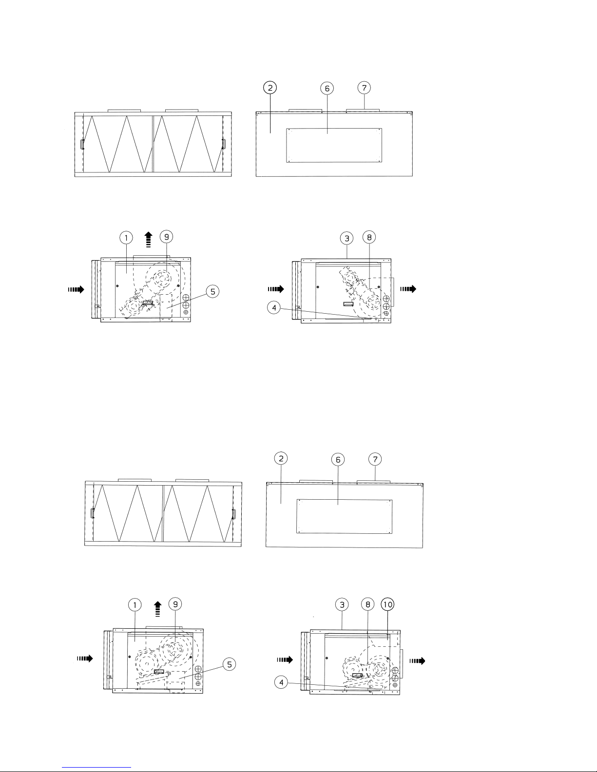
Indoor air discharge (50VZ/PZ)
The 50VZ/PZ units leave the factory with the indoor unit air
discharge set to vertical, as indicated in the dimensional figures. It
can be changed to horizontal discharge by following the steps
below:
Change from vertical to horizontal discharge without
changing the position of the motor
a. Detach the side access panels .
b. Remove the drive belt(s) (only sizes 50VZ/PZ 015,
045, 055, 065, 075).
c. Detach rear blanking plate and fan supply air ducts .
d. Detach the fans from the reinforcement flanges of the
upper panel and from the U-bracket .
e. Detach the U-bracket from the angle iron attached to
the base . Remove the U-bracket .
f. Install the fans, attaching them to the reinforcement
flanges of the rear panel and base support .
g. Install strengthening support , attaching it between the
fan and the roof (only sizes 50VZ/PZ 045-055-065-075).
h. Install blanking plate in the upper panel and fan supply
air ducts in the unit rear panel.
i. Replace the drive belt(s) and ensure that the tension and
alignment are correct (only sizes 50VZ/PZ 015, 045, 055,
065, 075).
j. Replace the access panels .
See figures 15 and 16.
Change from vertical to horizontal discharge with changing
the position of the motor
a. Detach the side access panels .
b. Remove the drive belt(s) .
c. Detach rear blanking plate and fan supply air ducts .
d. Detach the fans from the reinforcement flanges of the
upper panel and from the U-bracket .
e. Detach the U-bracket from the angle iron attached to
the base . Remove the U-bracket .
f. For units 50VZ/PZ 025, 030, 031 and 040 change the
motor to the other fan.
g. For units 50VZ/PZ 045, 055, 065 and 075 detach the drive
base together with the motor and reposition it on the
opposite side.
h. Remove the fan pulley and reposition it on the other
side.
i. Install the fans, attaching them to the reinforcement
flanges of the rear panel and base support .
j. Install strengthening support , attaching it between the
fan and the roof (only sizes 50VZ/PZ 045-055-065-075).
k. Install blanking plate in the upper panel and fan supply
air ducts in the unit rear panel.
l. Replace the drive belt(s) and ensure that the tension and
alignment are correct.
m. Replace the access panels .
See figures 15 and 16.
Indoor air discharge (40PZ)
The 40PZ units leave the factory with the air discharge set to
horizontal, as indicated in the dimensional figures. It can be
changed to vertical discharge by following the steps below:
Change from horizontal to vertical discharge without
changing the position of the motor
a. Detach the side access panels .
b. Remove the drive belt(s) (only sizes 40PZ 015, 045,
055, 065, 075).
c. Detach top blanking plate and fan supply air ducts .
d. Detach strengthening support between the fan and the
roof (only sizes 40PZ 045-055-065-075). Discard the
support.
e. Detach the fans from the reinforcement flanges of the rear
panel and from base support .
f. Install U-bracket , included with the unit, by attaching it
to base support .
g. Install the fans, attaching them to the reinforcement
flanges of the upper panel and to U-bracket .
h. Install blanking plate in the rear panel and fan supply
air ducts in the upper unit panel.
i. Replace the drive belt(s) and ensure that the tension and
alignment are correct (only units 40PZ 015, 045, 055, 065,
075).
j. Replace the access panels .
See figures 15 and 16.
Change from horizontal to vertical discharge with
changing the position of the motor
a. Detach the side access panels .
b. Remove the drive belt(s) .
c. Detach top blanking plate and fan supply air ducts .
d. Detach strengthening support between the fan and the
roof (only sizes 40PZ 045-055-065-075). Discard the
support.
e. Detach the fans from the reinforcement flanges of the rear
panel and from base support .
f. Install U-bracket , included with the unit, by attaching it
to base support .
g. For units 40PZ 025, 030, 031, 040 change the motor to the
other fan.
h. For units 40PZ 045, 055, 065, 075 detach the drive base
together with the motor and reposition it on the opposite
side.
i. Remove the fan pulley and reposition it on the other
side.
j. Install the fans, attaching them to the reinforcement
flanges of the upper panel and to U-bracket .
k. Install blanking plate in the rear panel and fan supply
air ducts in the upper unit panel.
l. Replace the drive belt(s) and ensure that the tension and
alignment are correct.
m. Replace the access panels .
See figures 15 and 16.
Page 17
17
Fig. 15 - Repositioning unit air discharge
(50VZ/PZ 025, 030, 031, 040
40PZ 025, 030, 031, 040)
Legend
Side access panel
Rear discharge panel
Top panel
Angle iron attached to the base
U-bracket
Blanking plate
Fan supply air ducts
Drive belt(s)
Fan pulley
Fig. 16 - Repositioning unit air discharge
(50VZ/PZ 015, 045, 055, 065, 075
40PZ 015, 045, 055, 065, 075)
Legend
Side access panel
Rear discharge panel
Top panel
Angle iron attached to the base
U-bracket
Blanking plate
Fan supply air ducts
Drive belt(s)
Fan pulley
Strengthening support
Front view
Front view
Rear view
Side view (vertical discharge) Side view (horizontal discharge)
Rear view
Side view (vertical discharge) Side view (horizontal discharge)
Page 18
18
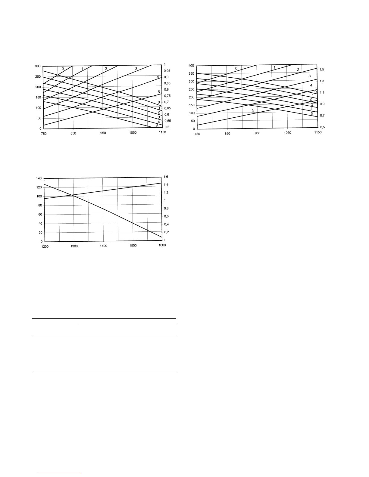
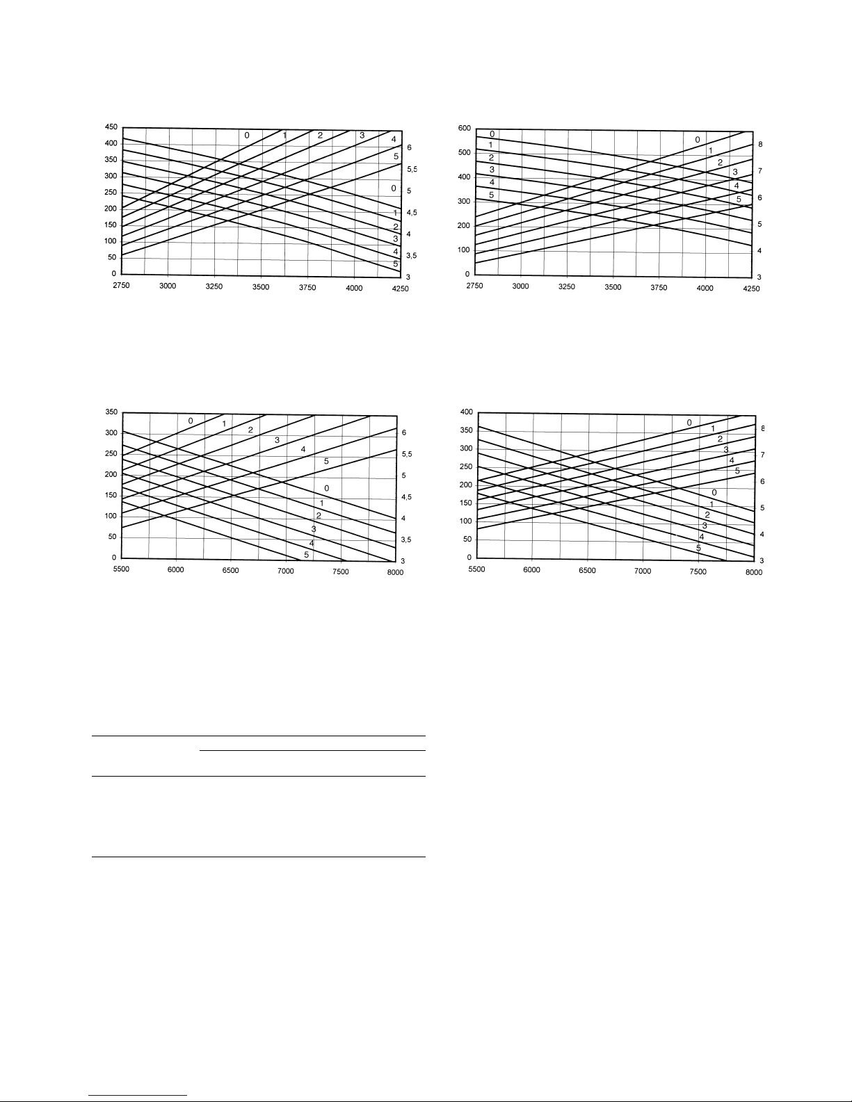
Fan performance
50VZ/PZ 015 indoor fan (40PZ 015) standard
transmission
50VZ/PZ 015 indoor fan (40PZ 015) optional larger
transmission
50VZ/PZ 015 outdoor fan (38VZ/PZ 015) standard
transmission
Indoor fan Outdoor fan
Curve Pulley open Standard Superior Standard Superior
r/s r/s r/s r/s
0 Closed 19.6 23.08
1 1 18.75 22.18
2 2 18.33 21.28
3 3 17.67 20.38
4 4 17 19.5
5 5 16.33 18.6
Factory 3.5 17.33 15.25
Available static pressure, Pa
Available static pressure, Pa
Available static pressure, Pa
Air flow, l/s
Power input, kW
Air flow, l/s
Power input, kW
Air flow, l/s
Power input, kW
Page 19
19
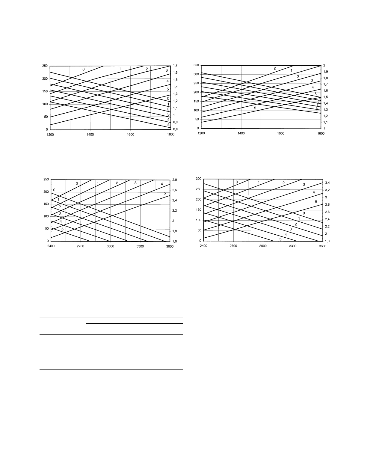
Fan performance
50VZ/PZ 025 indoor fan (40PZ 025) standard
transmission
50VZ/PZ 025 indoor fan (40PZ 025) optional larger
transmission
50VZ/PZ 025 outdoor fan (38VZ/PZ 025) standard
transmission
Indoor fan Outdoor fan
Curve Pulley open Standard Superior Standard Superior
r/s r/s r/s r/s
0 Closed 19.8 20.5 17.42 19.33
1 1 18.33 19.83 16.66 18.46
2 2 17.58 19.16 15.92 17.6
3 3 16.83 18.5 15.16 16.73
4 4 16.08 17.83 14.42 15.86
5 5 15.33 17.16 13.66 15
Factory 3.5/2* 16.45 15.92
* The first value is for the indoor unit pulley; the second value is for the outdoor unit
pulley
Available static pressure, Pa
50VZ/PZ 025 outdoor fan (38PV/PZ 025) optional
larger transmission
Air flow, l/s
Power input, kW
Available static pressure, Pa
Air flow, l/s
Power input, kW
Available static pressure, Pa
Air flow, l/s
Power input, kW
Available static pressure, Pa
Air flow, l/s
Power input, kW
Page 20
20
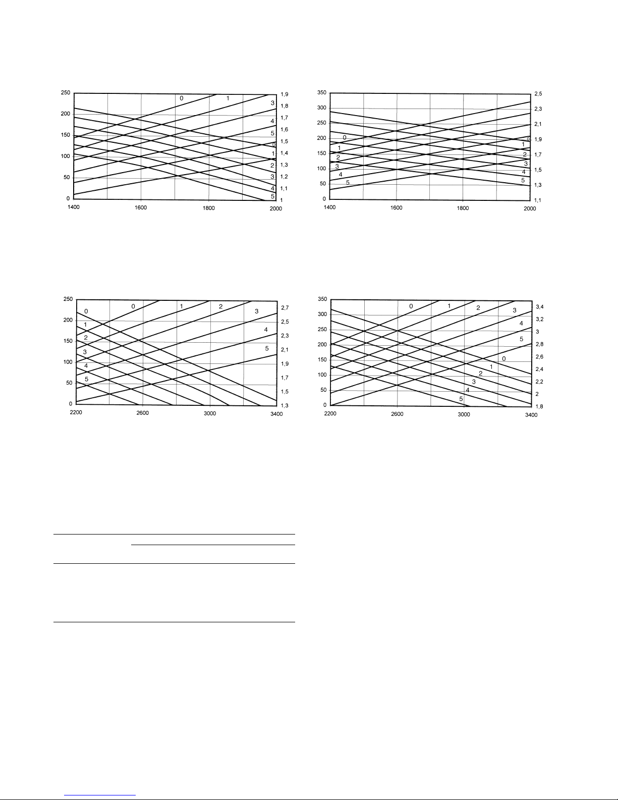
Fan performance
50VZ/PZ 030/031 indoor fan (40PZ 030/031) standard
transmission
50VZ/PZ 030/031 indoor fan (40PZ 030/031) optional
larger transmission
50VZ/PZ 030/031 outdoor fan (38VZ/PZ 030/031)
standard transmission
Indoor fan Outdoor fan
Curve Pulley open Standard Superior Standard Superior
r/s r/s r/s r/s
0 Closed 19.33 21.76 18.2 20.5
1 1 18.5 20.76 17.36 19.58
2 2 17.66 19.76 16.53 18.66
3 3 16.92 18.76 15.7 17.75
4 4 15.83 17.76 14.86 16.83
5 5 14.92 16.76 14.03 15.92
Factory 2.5/2* 17.29 16.53
* The first value is for the indoor unit pulley; the second value is for the outdoor unit
pulley
50VZ/PZ 030/031 outdoor fan (38PV/PZ 030/031)
optional larger transmission
Available static pressure, Pa
Air flow, l/s
Power input, kW
Available static pressure, Pa
Air flow, l/s
Power input, kW
Available static pressure, Pa
Air flow, l/s
Power input, kW
Available static pressure, Pa
Air flow, l/s
Power input, kW
Page 21
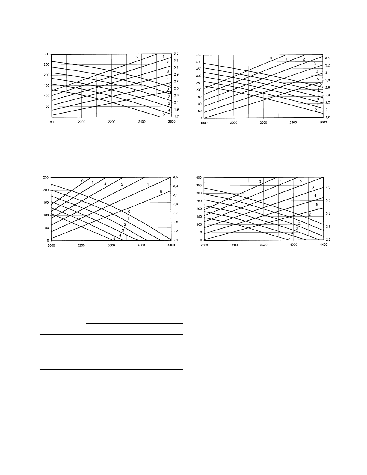
21
Fan performance
50VZ/PZ 040 indoor fan (40PZ 040) standard
transmission
50VZ/PZ 040 indoor fan (40PZ 040) optional larger
transmission
50VZ/PZ 040 outdoor fan (38VZ/PZ 040) standard
transmission
Indoor fan Outdoor fan
Curve Pulley open Standard Superior Standard Superior
r/s r/s r/s r/s
0 Closed 21.92 24.33 15 17
1 1 21.08 23.42 14.5 16.33
2 2 20.25 22.5 14 15.66
3 3 19.42 21.58 13.5 15
4 4 18.5 20.66 13 14.33
5 5 17.58 19.75 12.5 13.66
Factory 2.5/2.5* 19.84 13.75
* The first value is for the indoor unit pulley; the second value is for the outdoor unit
pulley
50VZ/PZ 040 outdoor fan (38PV/PZ 040) optional
larger transmission
Available static pressure, Pa
Air flow, l/s
Power input, kW
Available static pressure, Pa
Air flow, l/s
Power input, kW
Available static pressure, Pa
Air flow, l/s
Power input, kW
Available static pressure, Pa
Air flow, l/s
Power input, kW
Page 22
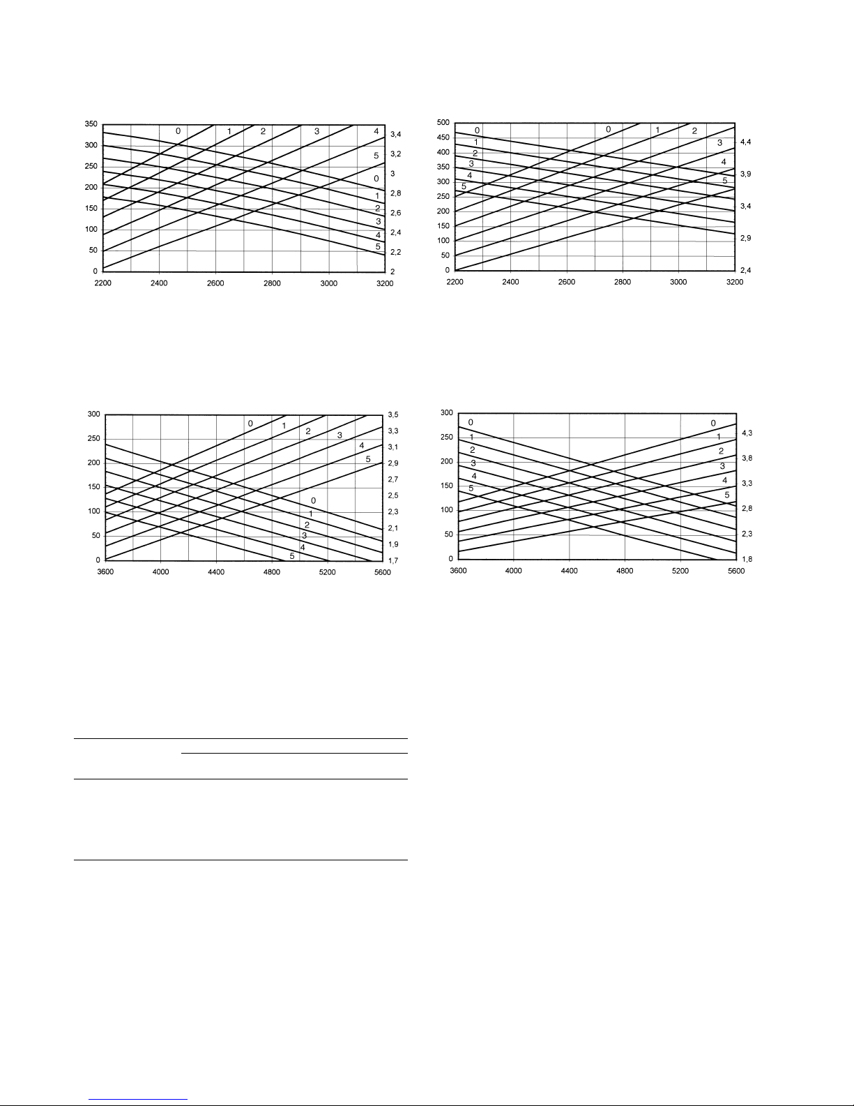
22
Fan performance
50VZ/PZ 045 indoor fan (40PZ 045) standard
transmission
50VZ/PZ 045 indoor fan (40PZ 045) optional larger
transmission
50VZ/PZ 045 outdoor fan (38VZ/PZ 045) standard
transmission
Indoor fan Outdoor fan
Curve Pulley open Standard Superior Standard Superior
r/s r/s r/s r/s
0 Closed 19.5 21.33 12.25 12.83
1 1 18.66 20.58 11.75 12.33
2 2 17.92 19.83 11.25 11.83
3 3 17.16 19.08 10.75 11.33
4 4 16.42 18.33 10.25 10.83
5 5 15.66 17.58 9.75 10.33
Factory 3/3* 17.16 10.75
* The first value is for the indoor unit pulley; the second value is for the outdoor unit
pulley
50VZ/PZ 045 outdoor fan (38PV/PZ 045) optional
larger transmission
Available static pressure, Pa
Air flow, l/s
Power input, kW
Available static pressure, Pa
Air flow, l/s
Power input, kW
Available static pressure, Pa
Air flow, l/s
Power input, kW
Available static pressure, Pa
Air flow, l/s
Power input, kW
Page 23
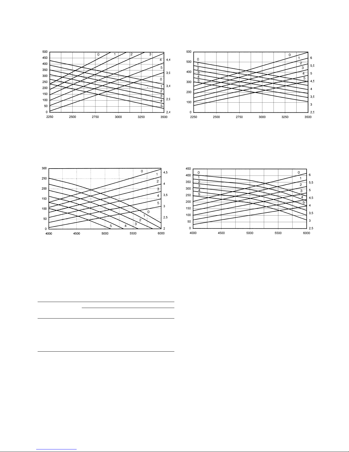
23
Fan performance
50VZ/PZ 055 indoor fan (40PZ 055) standard
transmission
50VZ/PZ 055 indoor fan (40PZ 055) optional larger
transmission
50VZ/PZ 055 outdoor fan (38VZ/PZ 055) standard
transmission
Indoor fan Outdoor fan
Curve Pulley open Standard Superior Standard Superior
r/s r/s r/s r/s
0 Closed 21.16 22.75 13 15
1 1 20.42 22 12.5 14.5
2 2 19.66 21.16 12 14
3 3 18.92 20.42 11.5 13.5
4 4 18.16 19.58 11 13
5 5 17.42 18.83 10.5 12.5
Factory 4/2* 18.16 12
* The first value is for the indoor unit pulley; the second value is for the outdoor unit
pulley
50VZ/PZ 055 outdoor fan (38PV/PZ 055) optional
larger transmission
Available static pressure, Pa
Air flow, l/s
Power input, kW
Available static pressure, Pa
Air flow, l/s
Power input, kW
Available static pressure, Pa
Air flow, l/s
Power input, kW
Available static pressure, Pa
Air flow, l/s
Power input, kW
Page 24
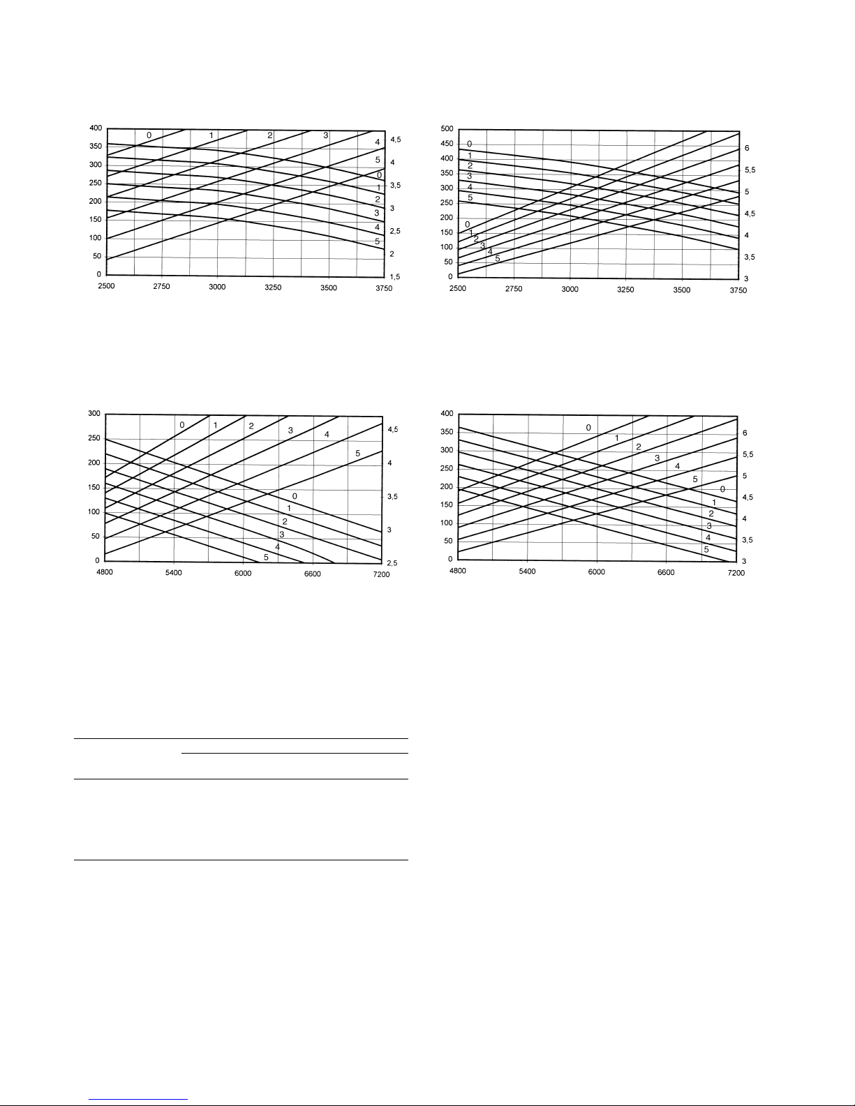
24
Fan performance
50VZ/PZ 065 indoor fan (40PZ 065) standard
transmission
50VZ/PZ 065 indoor fan (40PZ 065) optional larger
transmission
50VZ/PZ 065 outdoor fan (38VZ/PZ 065) standard
transmission
Indoor fan Outdoor fan
Curve Pulley open Standard Superior Standard Superior
r/s r/s r/s r/s
0 Closed 21.5 22.66 12.75 14.33
1 1 20.66 21.9 12.25 13.83
2 2 19.83 21.13 11.75 13.33
3 3 19 20.36 11.25 12.73
4 4 18.16 19.6 10.83 12.33
5 5 17.33 18.83 10.42 11.83
Factory 3.5/2* 18.58 11.75
* The first value is for the indoor unit pulley; the second value is for the outdoor unit
pulley
50VZ/PZ 065 outdoor fan (38PV/PZ 065) optional
larger transmission
Available static pressure, Pa
Air flow, l/s
Power input, kW
Available static pressure, Pa
Air flow, l/s
Power input, kW
Available static pressure, Pa
Air flow, l/s
Power input, kW
Available static pressure, Pa
Air flow, l/s
Power input, kW
Page 25
25
Fan performance
50VZ/PZ 075 indoor fan (40PZ 075) standard
transmission
50VZ/PZ 075 indoor fan (40PZ 075) optional larger
transmission
50VZ/PZ 075 outdoor fan (38VZ/PZ 075) standard
transmission
Indoor fan Outdoor fan
Curve Pulley open Standard Superior Standard Superior
r/s r/s r/s r/s
0 Closed 22.66 23.58 14.33 15
1 1 21.9 22.75 13.83 14.5
2 2 21.13 21.92 13.33 14
3 3 20.36 21.08 12.83 13.5
4 4 19.6 20.25 12.33 13
5 5 18.83 19.42 11.83 12.5
Factory 3/2.5* 20.36 13.08
* The first value is for the indoor unit pulley; the second value is for the outdoor unit
pulley
50VZ/PZ 075 outdoor fan (38PV/PZ 075) optional
larger transmission
Available static pressure, Pa
Air flow, l/s
Power input, kW
Available static pressure, Pa
Air flow, l/s
Power input, kW
Available static pressure, Pa
Air flow, l/s
Power input, kW
Available static pressure, Pa
Air flow, l/s
Power input, kW
Page 26
26
SAFETY CONSIDERATIONS
Installation and servicing of air conditioning equipment can be
hazardous due to system pressure and electrical components.
Only trained and qualified service personnel should install,
start-up or service air conditioning equipment. Untrained
personnel can perform the basic maintenance functions of
cleaning and replacing filters.
All other operations should be performed by trained service
personnel.
When working on air conditioning equipment, observe
precautions in the literature, tags and labels attached to the unit
and other safety precautions that may apply.
Follow all safety codes. Wear safety glasses and work gloves.
Use a quenching cloth for unbrazing operations.
WARNING: Before performing service or maintenance
operations on the unit, turn off the main power switch to the
unit. Electrical shock could cause personal injury.
All units are designed for ducted installation (indoor and/or
outdoor air discharge). If ducts are not used the installer must
place a protection grille in the discharge.
Only for use when repairing "Original Spare Parts". For
repairs, special attention must be paid to the correct
installation of the spare parts. The parts must always be
installed in their original position.
During unit operation, some of the refrigerant circuit elements
could reach a temperature in excess of 70°C so only trained or
qualified personnel should access areas protected by access
panels.
This unit should not be installed in an explosive atmosphere.
The unit can operate in normal radioelectric atmospheres in
residential, commercial and light industrial installations. For
other applications, please consult Carrier.
INSTALLATION
1. Inspect shipment. Inspect the unit. If it is damaged, or if
the shipment is incomplete, immediately file a claim with
the shipping company.
2. Check that the local power supply agrees with the
specification on the unit nameplate.
Siting the unit
Check the following points:
- The location must be able to support the unit operating
weight (see Table 1).
- Allow sufficient space for servicing and air flow around
the unit (see Fig. 8).
- Select a location free of dust or foreign matter which may
cause coil clogging.
- When installing the unit on the ground, select a site which
is not subject to flooding (outdoor unit).
- Consult all applicable rules and standards which govern
the installation of air conditioning equipment.
- Both the indoor and the outdoor unit are supplied with
transport skids. These skids must be removed, except
when vibration absorbers are installed.
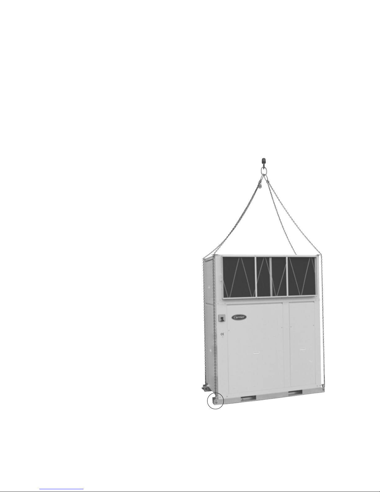
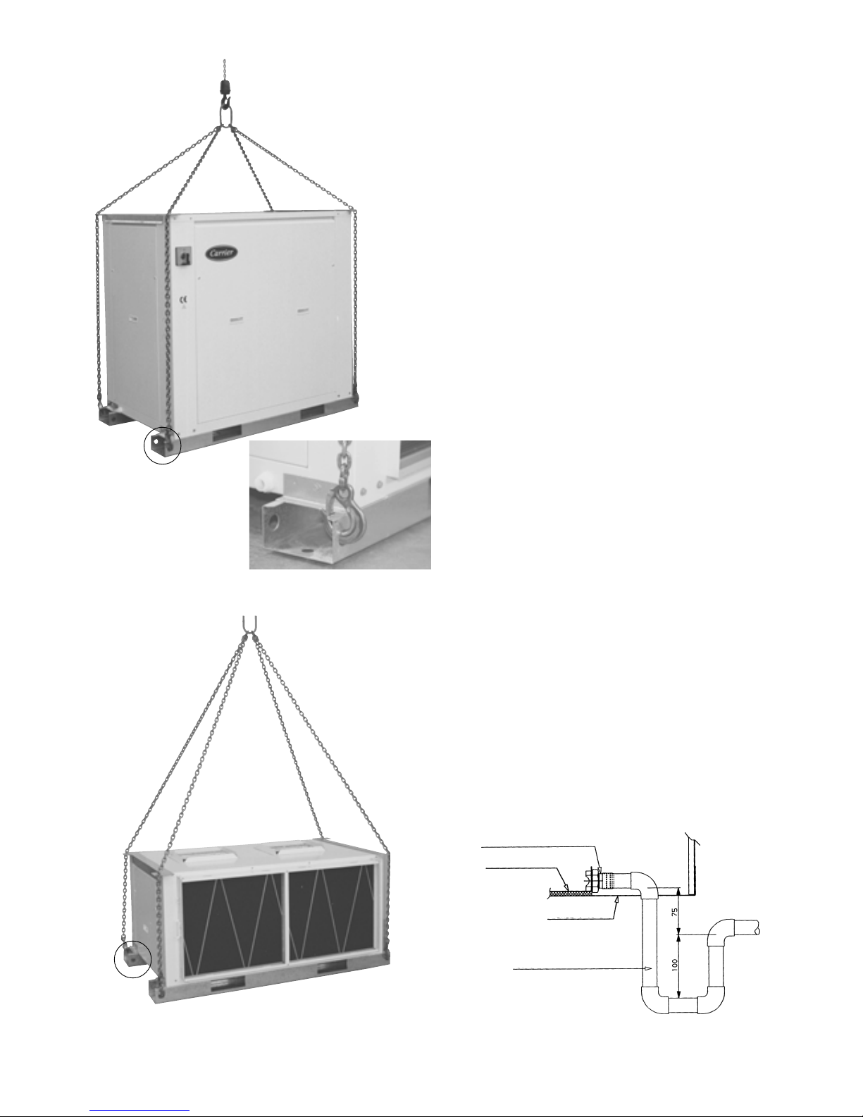
Rigging
1. When rigging, use spreaders to prevent damage to the
panels. Avoid violent movements.
2. To prevent damage while in transit, do not remove the
unit from the skid until it is at its final location.
3. Never roll or tip the unit more than 15°.
IMPORTANT: Make sure that all unit panels are fixed in place
before moving. Raise and set down the unit carefully.
Fig. 17 - Rigging (50VZ/PZ)
A
Page 27
27
Fig. 18 - Rigging (38VZ/PZ) Ductwork (indoor air discharge)
The ductwork dimensions should be determined in accordance
with the air flow to be carried, and the available static pressure
of the unit. The different air flows and static pressures which
each unit can supply, are shown in the fan performance tables.
It is recommended to observe the following considerations:
- Whatever type of ductwork is used, it should not be made
of materials which are flammable, or which give off toxic
gases in the event of a fire. The internal surfaces should be
smooth, and not contaminate the air which passes
through. It is recommended to use sheet metal ducts
which are adequately insulated to avoid condensation and
thermal leakage.
- At the points where the ducts join the unit, it is
recommended to use flexible connections which absorb
vibrations, prevent noise inside the ductwork and allow
access to the unit.
- Bends near the unit outlet should be avoided as much as
possible. If unavoidable, they should be as slight as
possible, and internal deflectors should be used when the
duct has large dimensions.
NOTE: All duct sizing and design work should be carried out
by qualified technicians.
Condensate drainage
50VZ/PZ and 38VZ/PZ units
The indoor unit evacuates condensate water via the condensate
pan of the outdoor heat exchanger (38VZ/PZ) which incorporates two male ø 3/4" gas drain connections, one for each
side of the unit. Depending on the installation site, either of
these drains can be used, and the unused drain should be plugged.
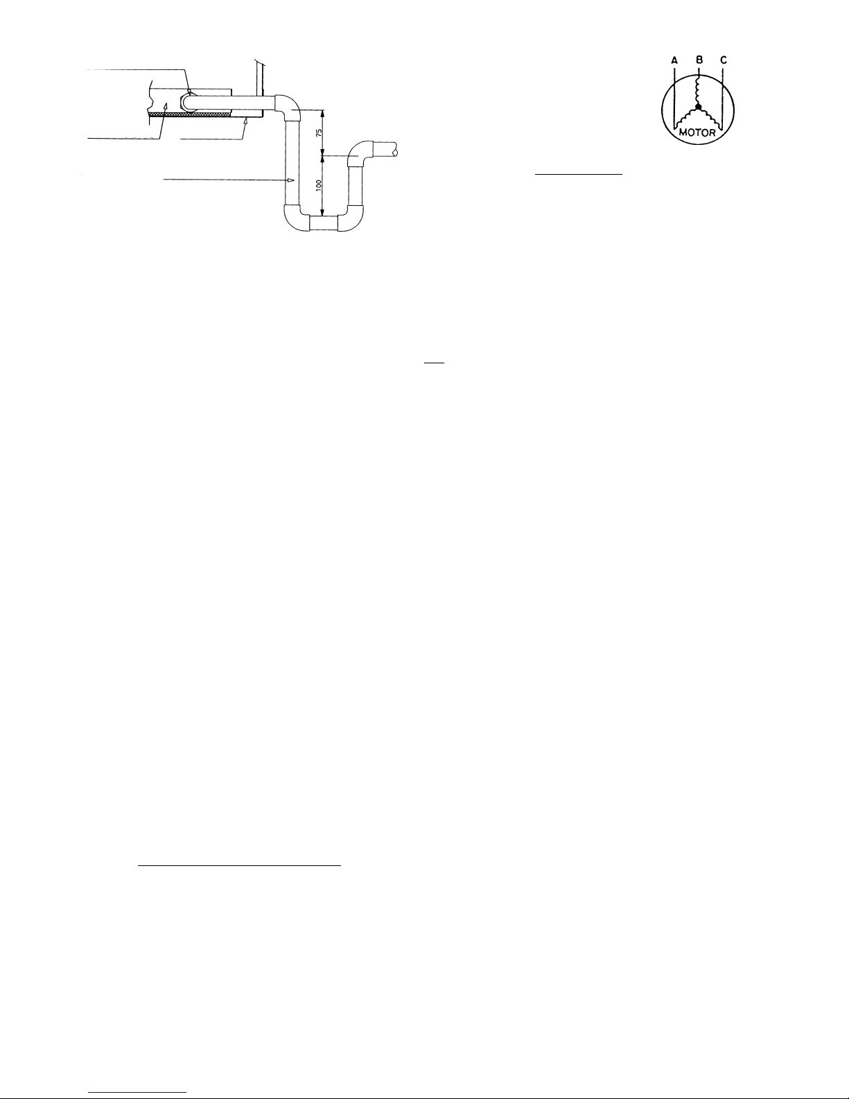
40PZ units
These units incorporate a condensate pan with a drain pipewith
an outside diameter of 25 mm.
The connection to the drain pipe can be vertical (Fig. 20) or
horizontal (Fig. 21).
• Vertical drain: Remove the prepunched knockout(s) in the
unit base.
• Horizontal drain: Remove the prepunched knockout(s) in
the side of the unit base.
Fig. 20 - Vertical drain (40PZ)
Fig. 19 - Rigging (40PZ)
IMPORTANT: The unit should be correctly levelled.
Field-supplied
Drain pipe OD 25 mm
Drain pan
Unit base
A
A
A
Page 28
28
Electrical connections
WARNING: To prevent electrical shock or equipment damage,
make sure disconnects are open before electrical connections
are made. If this action is not taken, personal injury may occur.
The unit power supply cables must not be lighter than normal
flexible polychloroprene covering cable (designation H05 RN-F).
Route all cables through the conduits incorporated in the unit
(50VZ/PZ or 38VZ/PZ) to the main disconnect switch terminals
(see wiring diagram).
Voltage to the unit must be within 2% of the voltage and 10%
of the current indicated on the nameplate. Contact your local
power company for correction of an incorrect line voltage.
Take special care when making the earth connection. This
cable must be connected first and it must be longer than
the power cable.
WARNING: Operation of the unit on improper line voltage
constitutes abuse and is not covered by the Carrier warranty.
IMPORTANT: To ensure the correct power supply, it is necessary
to first determine the cable section. This must take into account
the unit electrical data (see electrical data table) and the line
length (max. permissible voltage drop 5%).
If the unit includes electric heat, this must be taken into account
for the supply line sizing.
Never operate a unit if the voltage imbalance exceeds 2%. The
following formula must be used to determine the percentage of
voltage imbalance.
Voltage imbalance % =
Largest deviation from average voltage
Average voltage
Fig. 21 - Horizontal drain (40PZ)
Field-supplied
Drain pipe OD 25 mm
Drain pan
Unit base
Example:
Nominal supply: 400-3-50
AB = 404 V
BC = 399 V
AC = 394 V
Average voltage = 404 + 399 + 394 = 399 = 400 V
3
Determine maximum deviation from average voltage:
AB = 404 - 400 = 4
BC = 400 - 399 = 1
AC = 400 - 394 = 6
Largest deviation is 6 volts. Percentage voltage imbalance is
therefore:
6 x 100 = 1.5%
400
VERY MPORTANT: The installer must protect the unit power
supply line with automatic disconnect devices, a thermalmagnetic switch and a differential disconnect switch, suitable
for the installation and in according with applicable legislation.
Electrical connection between the units (38VZ/PZ and
40PZ)
The general power supply for the complete system (indoor and
outdoor unit) must be made via the outdoor unit (38VZ/PZ).
Consult the wiring diagram that is supplied with the units. This
will show all power connections to be made between the 38VZ/
PZ unit and the 40PZ unit.
The unit connection cables must not be lighter than normal
flexible polychloroprene covering cable (designation H05 RN-F)
with a wire section that is adequate for the 40PZ unit power
consumption.
The power supply for the electric heater of the indoor unit must
be provided from the main disconnect switch.
Thermostat connection
Thermostat/unit connection must be via a loom (wire section
1 mm2) manufactured in accordance with the wiring diagram
accompanying the unit.
Follow the instructions supplied with the control for thermostat
assembly and handling.
The general rules below should be taken into account:
Page 29
29
NOTE 1: This control is compatible with any kind of
electromechanical or electronic control (without anticipation
resistors) with the following features:
- Voltage at 24 V AC
50VZ units standard connections:
R Connection to 24 V
L Protection device indication
C Common 24 V
G Ventilation
Y1 First stage cooling
Y2 Second stage cooling
W1 First stage heating (option)
W2 Second stage heating (option)
50PZ units standard connections:
R Connection to 24 V
L Protection device indication
C Common 24 V
G Ventilation
Y1 First stage (cooling/heating)
Y2 Second stage (cooling/heating)
W1 First stage heating (option)
O Reversing valve*
* The O connection is activated in cooling.
NOTE 2: If the thermostat wiring is incorrect, the control will
be blocked (red LED on) and all the outlets will be deactivated
when unit power is supplied.
NOTE 3: The thermostat cables should be separate from any
220 V or 380 V cable.
Refrigerant line connections (38VZ/PZ and 40PZ)
To guarantee correct unit performance ensure that the line
length and number of bends are kept to a minimum. Avoid pipe
kinking by using large radius bends.
IMPORTANT: Always use refrigerant-grade deoxidized and
dehydrated copper tubing between the indoor and outdoor
units.
Before connecting the refrigerant lines carefully follow the
steps below:
- Remove the nitrogen holding charge from the refrigerant
circuits.
- Select the diameter of the copper tubing according the the
units installed and according to the distance between the
indoor and outdoor units.
- Use silver alloy rod for soldering purposes, and ensure
that this work is done in a nitrogen atmosphere.
- To avoid oxidation insulate the refrigerant lines
adequately.
- Pull a vacuum in the refrigerant circuit until a pressure of
6.9 Pa is maintained for at least 2 hours.
- Charge the refrigerant circuit with the necessary amount
of R-407C refrigerant (in accordance with table 1 and the
length of the refrigerant lines).
- Check there are no refrigerant leaks.
Refrigerant line selection
General
When designing refrigerant lines the following must be kept in
mind:
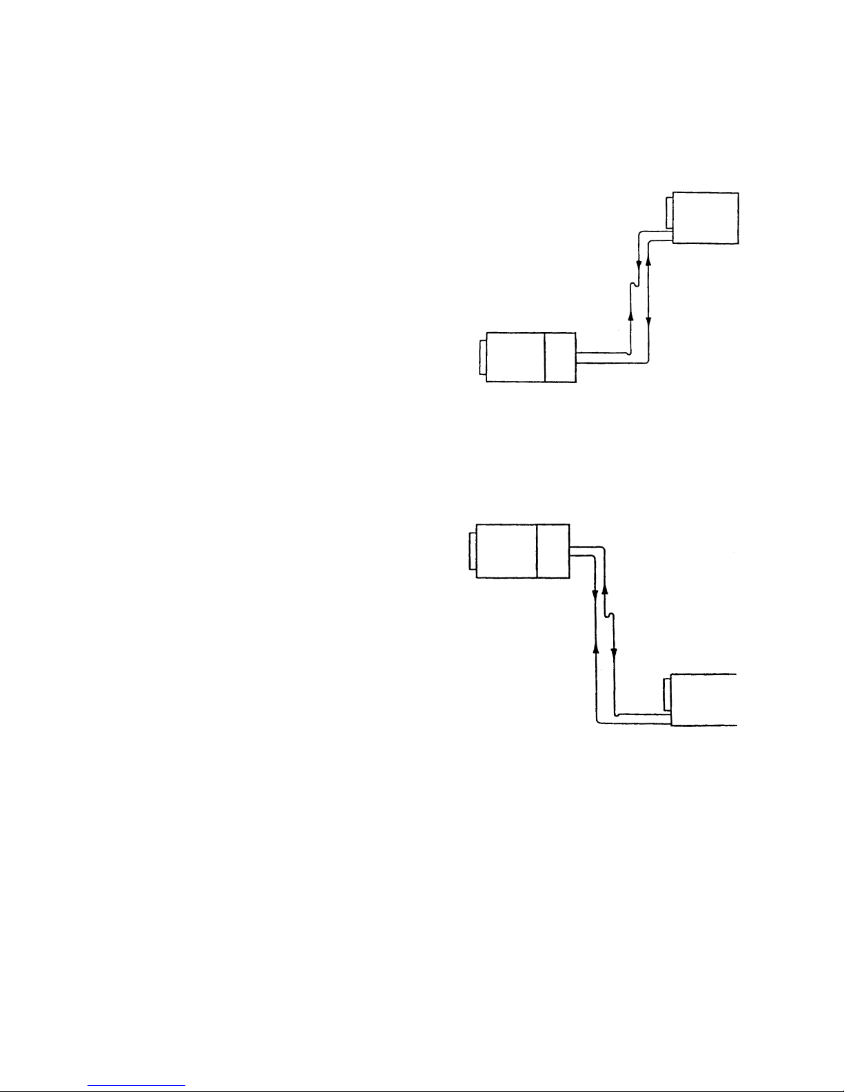
- Depending on the unit arrangement:
Fig. 22 - Refrigerant lines option A
Heat pump (discharge line)
Outdoor unit
Indoor unit
Heat pump
Liquid line
Cooling
Gas line
Cooling (suction line)
Suction/discharge line:
- A siphon at the base of the vertical pipe run and intermediate siphons every 8 m or oil separators are needed.
- Most unfavourable condition: the suction speed in the
vertical pipe run must be more than 6 m/s.
Fig. 23 - Refrigerant lines option B
Heat pump (discharge line)
Outdoor unit
Indoor unit
Heat pump
Liquid line
Cooling
Gas line
Cooling (suction line)
Suction/discharge line:
- For heat pumps a siphon is required in the base of the
vertical pipe run.
- The intermediate siphon can be omitted.
- For cooling only units siphons are not required.
- Most unfavourable condition: the suction/discharge
speed in the vertical pipe run must be more than 6 m/s.
Page 30
30
For both option A (Figure 22) and option B (Figure 23) the
following conditions should be observed:
- The maximum speed permitted in any line is 15 m/s.
- Suction line must be insulated and have a 2% slope towards
the compressor and the horizontal pipe run.
- In long pipe runs it may be necessary to adjust the oil charge.
- If the liquid line flow is downward, it is necessary to
install pressure equalizer for heights above 10 m.
- The liquid should be subcooled by at least 1 K at the
restrictor inlet. In this case, if the liquid line flow is
upward and the pipe is longer than 15 m, it must be
subcooled by 1 K for each 3.5 m in excess of 15 m.
- Subcooling can be contained in the liquid and suction
lines (maximum 15 m) of the units.
- For each metre of refrigerant pipe installed, refrigerant has
to be added in accordance with table 3.
Table 3 - Refrigerant charge (g/m)
Diameter 1/2" 5/8" 3/4" 7/8" 1-1/8" 1-3/8"
Liquid line 75 120 180 250 420 645
Suction line 14 23 34 47 81 123
Sizing
Suction/discharge line
The gas line is the suction line in cooling and the discharge
line in heat pump operation. Its diameter is calculated for the
most unfavourable condition. This can be as a suction or as a
discharge line and has to be checked afterwards for the other
line type.
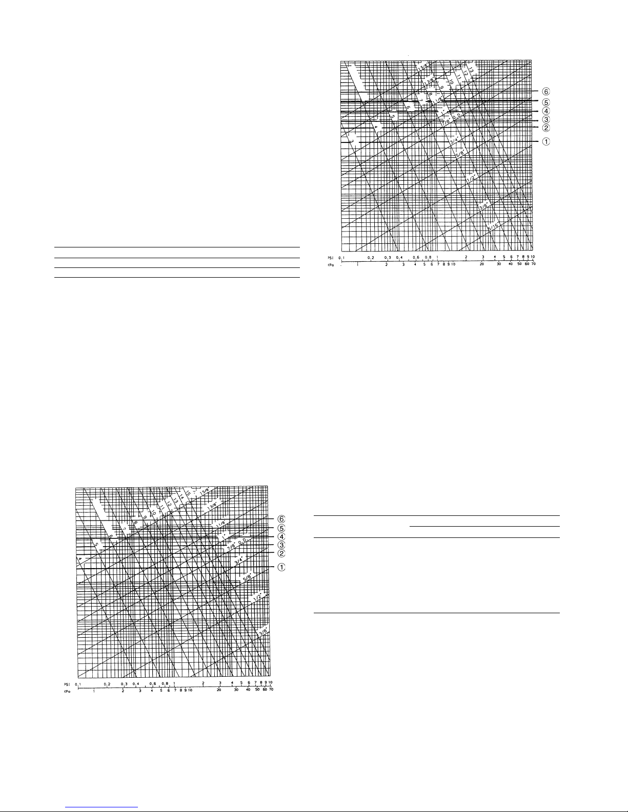
For example, in the configuration shown in option A (the suction
speed will produce the most unfavourable condition, and the
gas line diameter will be calculated for suction. Afterwards, the
calculation should be checked for discharge. The diameter
calculation for suction and discharge lines is done in the same
way using the corresponding drawing (see Figs. 24 and 25).
Fig. 24 - Suction line
Fig. 25 - Discharge line
Legend:
38VZ/PZ 015 + 40PZ 015
38VZ/PZ 031 + 40PZ 031
38VZ/PZ 040 + 40PZ 040
38VZ/PZ 025 + 40PZ 025
38VZ/PZ 045 + 40PZ 045
38VZ/PZ 030 + 40PZ 030
38VZ/PZ 055 + 40PZ 055
38VZ/PZ 065 + 40PZ 065
38VZ/PZ 075 + 40PZ 075
Legend:
38VZ/PZ 015 + 40PZ 015
38VZ/PZ 031 + 40PZ 031
38VZ/PZ 040 + 40PZ 040
38VZ/PZ 025 + 40PZ 025
38VZ/PZ 045 + 40PZ 045
38VZ/PZ 030 + 40PZ 030
38VZ/PZ 055 + 40PZ 055
38VZ/PZ 065 + 40PZ 065
38VZ/PZ 075 + 40PZ 075
From Figures 24 and 25, for the selected unit we can obtain the
pressure drop corresponding to 10 m of equivalent length for
each diameter.
For other equivalent lengths, the pressure drop is obtained in
direct proportion. The total pressure drop for the line (sum
corresponding to the vertical and horizontal pipe runs) must
not be higher than 20 kPa.
Liquid line:
The liquid line diameter can be selected using table 4.
Table 4 - Liquid line
Models Total equivalent length
Up to 10 m From 10-30 m From 30-50 m
38VZ/PZ 015 + 40PZ 015 5/8" 5/8" 5/8"
38VZ/PZ 025 + 40PZ 025 5/8" 5/8" 3/4"
38VZ/PZ 030 + 40PZ 030 5/8" 3/4" 3/4"
38VZ/PZ 031 + 40PZ 031 5/8" 5/8" 5/8"
38VZ/PZ 040 + 40PZ 040 5/8" 5/8" 5/8"
38VZ/PZ 045 + 40PZ 045 5/8" 5/8" 3/4"
38VZ/PZ 055 + 40PZ 055 5/8" 3/4" 3/4"
38VZ/PZ 065 + 40PZ 065 5/8" 3/4" 7/8"
38VZ/PZ 075 + 40PZ 075 3/4" 7/8" 7/8"
Necessary checks/precautions before start-up
- Ensure that all electrical connections are properly
tightened.
- Ensure that the unit is level and well-supported.
- Check the condition of the ductwork in case damage has
occurred during installation.
- The air filter should be clean and in place.
- All the panels should be fitted and firmly secured with the
corresponding screws.
- Make sure that there is sufficient space for servicing and
maintenance purposes.
SPEED (m/s)
SPEED (m/s)
Page 31

31
- Check the drain connections.
- Ensure that there are no refrigerant leaks.
- Confirm that the electrical power source agrees with the
unit nameplate rating.
- Make sure that compressors float freely on the mounting
springs.
WARNING: The compressors are mounted on vibration
isolators. Do not loosen or remove the support mounting bolts.
- Check for proper fan rotation.
Refrigerant charge
Gas tightness testing and dehydration
50VZ/PZ units are shipped fully charged with refrigerant R-407C
ready for operation. If, when the unit is run, symptoms of loss
of charge (for example, low pressure switch tripping or
abnormally low cooling capacities) are detected, first conduct a
leak test followed, if necessary, by a gas tightness test using
compressed nitrogen. For the latter all refrigerant must be
removed from the circuit. Transfer the refrigerant to a storage
tank and then rinse the circuit. For your information, we are
listing here some precautions that need to be taken into
consideration, when working with these units.
Refrigerant guidelines for R-407C
Refrigerant R-407C consists of a non-azeotropic blend of 23%
of R-32, 25% of R-125 and 52% of R-134a, and is characterised by the fact that at the time of the change in state the
temperature of the liquid/vapour mixture is not constant. All
checks must be pressure tests, and the appropriate pressure/
temperature ratio table must be used for the interpretation of
the values.
Leak detection is especially important for units charged with
refigerant R-407C. Depending on whether the leak occurs in
the liquid or the vapour phase, the proportion of the different
components in the mixture remaining in the unit is not the
same.
The following basic guidelines must be observed:
• Leaks must be repaired immediately by qualified
personnel.
• Refrigerant must never be discharged to the atmosphere.
• Use a refrigerant reclaim unit.
• Any loss of oil from the system during maintenance must
be stopped immediately and the collected oil must by
removed in accordance with applicable regulations
38VZ/PZ and 40PZ units are supplied with a nitrogen holding
charge. This must be removed before soldering the connecting
refrigerant lines to the unit. Once the soldering has been
completed, the complete refrigerant circuit must be evacuated
then the correct quantity of R-407C refrigerant for each system
must be charged.
WARNING: If any brazing is to be done the refrigerant circuit
must be filled with nitrogen. Combustion of refrigerant
produces toxic phosgene gas.
VERY IMPORTANT:
- Never use the compressor as a vacuum pump.
- If more refrigerant is needed add gas very slowly via the
suction line. Liquid refrigerant must never be introduced
into the suction line.
- Do not overcharge with refrigerant.
START-UP
Actual start-up should only be done under the supervision of a
qualified refrigeration mechanic. These units include the
Master Link II electronic control. The operation of the control
is explained in the instructions accompanying each unit.
Initial checks
With the unit in operation, ensure that the values shown on the
high and low pressure gauges are within the normal limits. It is
advisable to simulate unit shutdown due to high and low
pressure, in order to make sure that the pressurestats work
properly. To do so, proceed as follows:
- High pressure shutdown: Completely cover the outdoor
air inlet, or disconnect the outdoor fan and motor. The
unit should stop at a pressure of 2844 kPa.
- Low pressure shutdown: Cover the indoor air inlet, or dis-
connect the indoor fan and motor. Observe the low
pressure
gauge. The unit should stop at a pressure of 265 kPa.
In both cases, after a reasonable time, reset the unit through the
remote control as previously indicated.
Check that the motor and compressor consumptions are
approximately the same as those shown on the unit nameplate.
Consumption data is also given in Table 2.
Refrigerant system description
The refrigerant circuit incorporates the following primary
elements:
- Refrigerant-air heat exchanger: made of high quality
copper tubes and pretreated aluminium fins, for extra
corrosion resistance and greater protection than offered by
copper fins.
- Refrigerant lines: made completely of high quality
copper.
- Expansion valve or metering device.
- Compressors: hermetic reciprocating or scroll
compressors depending on model, cooled by suction gas.
They incorporate internal protection.
- Filter drier and Schrader valves.
- Safety elements: high, low pressurestat.
- All units are supplied with the correct refrigerant charge.
- The split system units are supplied with a nitrogen
holding charge which must be evacuated and replaced
with the right refrigerant charge for the unit size and the
connection lines.
Compressor replacement
When an internal fault occurs, the compressor must be
replaced. This must be done as detailed below:
- Disconnect the unit from the electrical supply.
- Remove the panels.
Page 32

32
Table 7 - Heat pump operation
Zone Air temperature
Dry bulb Wet bulb
Indoor
Maximum 27°C-
Outdoor
Maximum 24°C18°C
Minimum -15°C-
OPTIONS AND ACCESSORIES
Option Accessory
Head pressure control kit x x
Electric heating x x
Compressor crankcase heater (standard on 50PZ) x x
Hot water coil x x
Economizer x
Outdoor air filter x x
User interface x
Protection grille x x
Minimum opening potentiometer x x
Volt-free contacts x
Optional communications x x
Return air sensor x x
Superior drive x
38VZ/PZ for vertical discharge x
Hot water heating coil
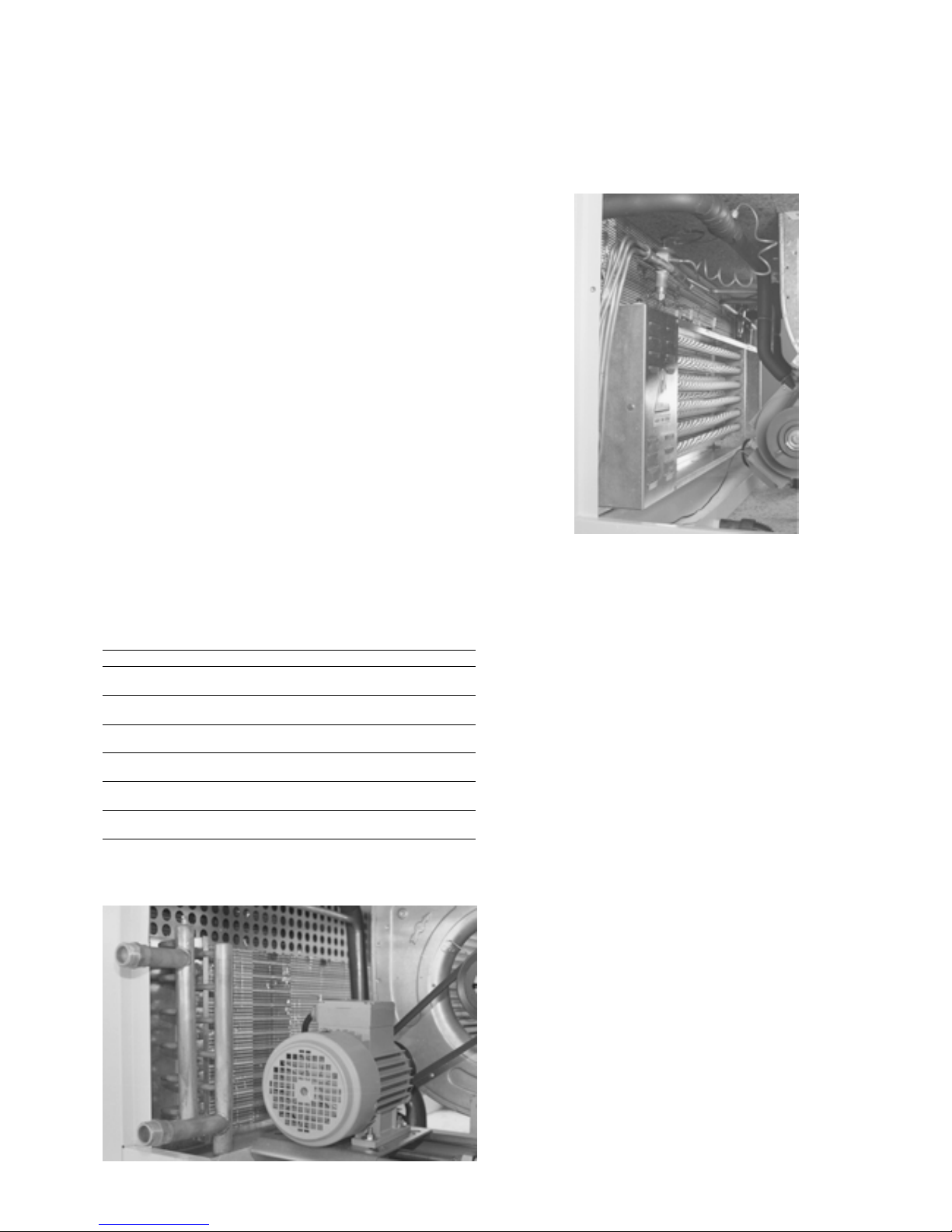
This option/accessory consists of the water heating coil, the air
flow equalising plate, the side access panel and fixing
components.
The heating coil performances are in accordance with Eurovent
conditions and are shown in tables 8 and 9.
Table 8
Unit 015 025 030 031 040 045 055 065 075
Heating capacity kW* 9.6 17.5 19.6 19.6 27.3 33.4 35.3 41 43.8
Water flow l/s 0.46 0.84 0.94 0.94 1.31 1.60 1.69 1.96 2.09
Pressure drop kPa 13 20 14.5 14.5 13.5 21 23 33.5 37.5
* Indoor air temperature 20°C and entering/leaving water temperature 50°C/45°C.
Table 9
Unit 015 025 030 031 040 045 055 065 075
Heating capacity kW* 15.2 27.9 30.4 30.4 43.4 51.5 54.6 63.9 68.5
Water flow l/s 0.36 0.67 0.72 0.72 1.04 1.23 1.31 1.52 1.64
Pressure drop kPa 9 13 9 9 9 13 14.5 21 24
* Indoor air temperature 20°C and entering/leaving water temperature 70°C/60°C.
Water connection
The entering and leaving water connections are all threaded
male gas connections with the diameters shown in Table 10.
Table 10
Unit 015 025 030 031 040 045 055 065 075
Ø connection 1” 1” 1-1/4” 1-1/4” 1-1/4” 1-1/2” 1-1/2” 1-1/2” 1-1/2”
- Remove the gas from the refrigerant circuit using recovery
equipment to avoid harming the atmosphere.
- Electrically disconnect the compressor.
- Unbraze or unscrew the suction and discharge lines,
taking care not to damage the rest of the components.
- Remove the fastenings from the compressor.
- Replace the compressor, ensuring that it contains
sufficient oil.
- Braze or screw in the lines.
- Connect the compressor according to the wiring diagram.
- Evacuate the compressor.
- Fill in the refrigerant charge indicated on the nameplate,
plus the required charge for the refrigerant connection
lines, if the system is a split system.
NOTE: This operation must be done by a qualified technician.
Description of unit protection devices
The unit includes the following unit protection devices:
- Internal compressor protector to avoid overheating.
- Short-cycle protection (included in the main electronic
board).
- Outdoor fan motor thermomagnetic switch.
- Indoor fan motor thermomagnetic switch.
- High pressurestat - This protects the unit against
excessive condensing pressure. The high pressurestat has
factory-fixed non-adjustable settings. To check, see
section Initial checks.
- Low pressurestat - This protects the unit against
excessive low pressure in the evaporator. The low
pressurestat has factory fixed non-adjustable settings. To
check, see section Initial checks.
CAUTION: When any of these cuts out, the unit stops and will
not re-start until the contacts have been reclosed after
rectification of the fault.
Table 5 - Pressure switch settings
Cut-out Cut-in Reset
High pressurestat *2844 kPa 1863 kPa Automatic
Low pressurestat *265 kPa 363 kPa Automatic
* Factory-fitted
WARNING: Alteration of factory settings other than the design
set-point, without manufacturer's authorisation, may void the
warranty.
Operating limits
These units have been designed to operate within the following
limits:
Table 6 - Cooling operation
Zone Air temperature
Dry bulb Wet bulb
Indoor
Maximum 35°C21°C
Minimum 19°C14°C
Outdoor
Maximum 46°CMinimum 19°C* -
* With the optional head pressure control, the unit can operate with temperatures below 19°C.
Page 33
33
Installation
The standard installation of the water heating coil is made by
positioning the connection manifolds on the same side as the
motor of the evaporator unit. If necessary, it can be connected
to the opposite side. In this case the coil must be turned by 180°.
The installation sequence is as follows:
a. Disconnect the power supply to the unit.
b. Remove the side access panels.
c. Loosely screw in the 4 screws provided to attach the
heating coil to the headers of the evaporator coil (leaving
a free space of 3-4 mm untightened).
d. Install the heating coil, inserting the semi-attached screws
in the grooves of the headers.
e. Fix the 4 screws provided to attach the heating coil.
f. Install the perforated plate in the upper part of the coil,
covering the space that remains between the coil and the
unit top panel.
g. Connect heating coil sensor BT4 to terminals 39 and 40 of
the indoor unit terminal box, and from here to terminals
39 and 40 of the outdoor unit.
h. Change the position of dipswitch 3 on the main board AO
to position “ON”.
i. For water heating coils with a proportional valve an
extension board A2 must be installed and connected in
accordance with the wiring diagram for this option. In all
cases, both for the all-or-nothing control valve and for
the proportional valve the elctrical conections must be
made in accordance with the wiring diagram.
j. Install the blanking plate, supplied with the coil, on the cor-
responding side, after punching out the prepunched holes for
the entering and leaving water connections of the manifolds.
Table 11
Model Unit 015 025 030 031 040 04 5 055 065 075
6 kW Cooling only x
Heat pump x
12 kW Cooling only xxx
Heat pump xxxxx
15 kW Cooling only xx
Heat pump xxxx
18 kW Cooling only
Heat pump xxxx
18 (9+9) kW* Cooling only xx
Heat pump
24 (12+12) kW* Cooling only xxxx
Heat pump
* 2-stage heating
Fig. 26
Electric resistance heaters
This option/accessory consists of a frame with shielded electric
heaters and a control box, incorporated in the same frame, with
all electrical and protection components required to guarantee
total safety. For the available capacities see Table 11.
Fig. 27
Installation
The standard installation of the electric heating coil is made by
positioning the control box on the same side as the motor of
the evaporator unit.
If necessary, it can be positioned on the opposite side. In this
case the coil must be turned by 180°.
VERY IMPORTANT: If the coil is installed on the opposite side,
it is NECESSARY to change the position of the two thermal
protectors to the opposite longitudinal beam, i.e. the thermal
protectors must always be positioned in the upper part of the
coil.
The installation sequence is as follows:
a. Disconnect the power supply to the unit.
b. Remove the side access panels.
c. Loosely screw in the 4 screws provided to attach the
electric heater to the headers of the evaporator coil
(leaving a free space of 3-4 mm untightened).
d. Install the electric heater, inserting the semi-attached
screws in the grooves of the headers.
e. Fix the 4 screws provided to attach the electric heater.
f. Make all electrical connections in accordance with the
wiring diagram supplied with this option.
g. Install the blanking plates in their correct positions.
Page 34
34
SERVICE
Indoor fan air adjustment
The drive is factory set in accordance with the tables on pages
18-25. When indoor pressure and air flow requirements differ
from nominal ratings, the motor pulley can be adjusted for
different available static pressure values.
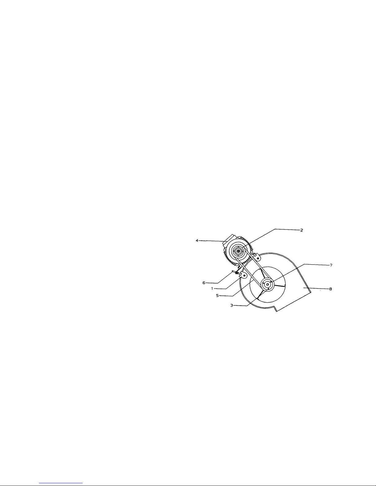
To change the fan speed (see Fig. 28):
1. Move the motor along its track in order to remove the
belt.
2. Loosen the pulley setscrews and rotate as necessary.
3. Tighten the setscrews .
4. Replace the belt(s) in the channel of the pulley.
5. Tighten the belt(s), using the tension screw nut and
washer .
To align fan and motor pulleys:
1. Loosen fan pulley setscrews. Slide fan pulley along the
pulley shaft and align with the motor using a ruler,
making sure that it is parallel to the belt.
2. Tighten the fan pulley setscrews.
To adjust the belt tension, loosen the motor mounting plate
bolts and slide the motor mounting plate until the belt is as
shown in Fig. 29.
Fig. 28 - Fan speed adjustment
Legend
1 Motor support
2 Motor pulley
3 Setscrews
4 Motor
5 Belt
6 Tensioning screw
7 Fan pulley
8 Fan scroll
GENERAL MAINTENANCE
ATTENTION: Before starting any servicing or maintenance
operation on the unit, make sure that the power supply has been
disconnected. A current discharge could cause personal injury.
In order to obtain maximum performance from the unit special
attention should be paid to the following points:
- Electrical connections: The supply voltage should be
±10% of the nominal voltage limits.
Ensure that no faulty contacts exist in the terminal blocks,
contactor boards, etc. Make sure that all the electrical
connections are properly tightened, and that all the
electrical components (contactors, relays, etc) are firmly
secured to the corresponding rails.
Pay special attention to the condition of the connecting
cables between the control elements and the electrical box,
and to that of the unit power supply cable. They should
not be twisted and there should be no slits or notches in
the insulation. Check the starting and running consumptions
are within the limits specified in the corresponding
technical information.
- Drainage: Frequently check that the drain is not
obstructed, and that the condensate pan is clean and level.
- Inlet air filter: This should be cleaned periodically. The
frequency depends on the purity of the entering air. The
filter may be cleaned with a household vacuum cleaner, or
by immersing it in water.
- Refrigerant circuit: Ensure that there is no leakage of
refrigerant or oil from the compressor. Check that the high
and low side operating pressures are normal. Make sure
that the coils are not dirty. If necessary an optional filter
may be placed at the outdoor air inlet. Check for unusual
compressor noise.
- Controls: Check the operation of all electric controls,
high and low pressurestats, etc.
Page 35
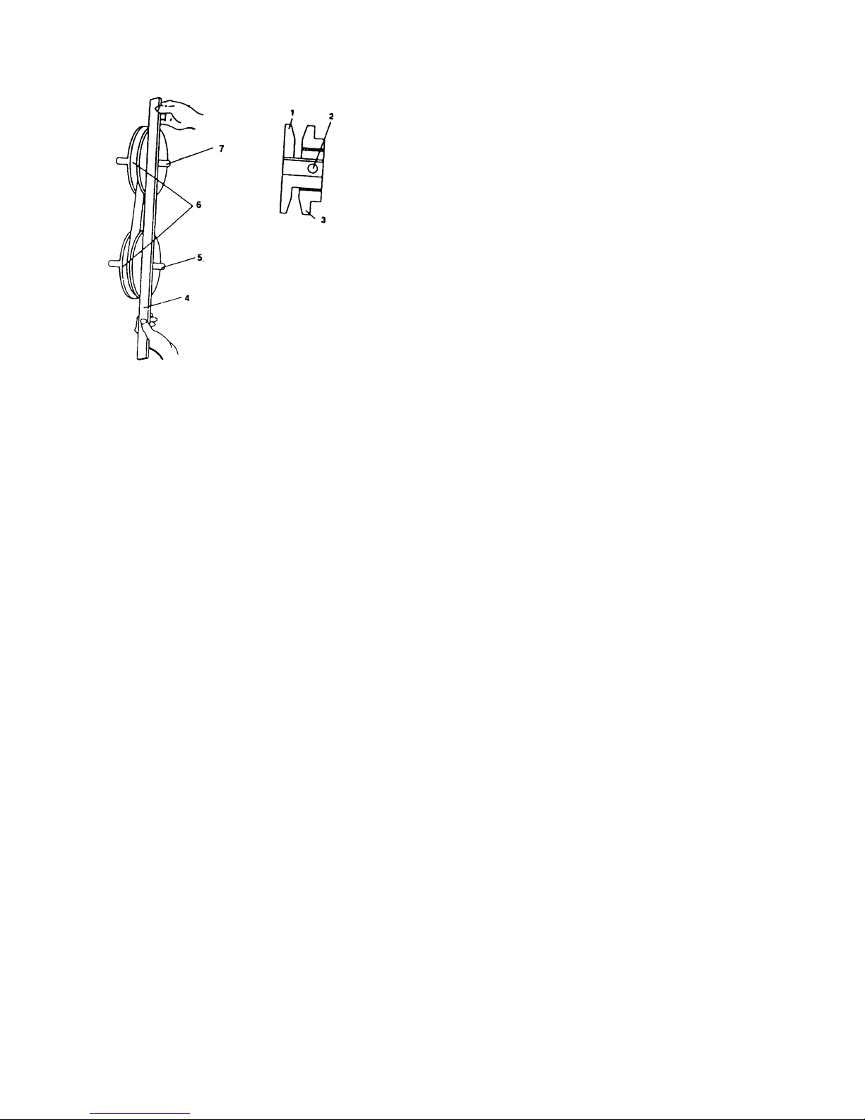
35
1 Fixed flange
2 Setscrews
3 Movable flange
4 Straight-edge must be parallel with belt
5 Motor and fan shafts must be parallel
6 Pulleys
7 Motor and fan shafts must be parallel
Fig. 29 - To align fan and motor pulleys
Lubrication
Both the motors and the fans have factory lubricated and sealed
bearings, and need no further lubrication.
The compressor has its own oil supply and oil should not be
added unless a leak has occurred.
Servicing recommendations
- Before replacing any of the elements in the cooling
circuit, ensure that the entire refrigerant charge is removed
from both the high and low pressure sides of the unit.
- The control elements of the cooling system are highly
sensitive. If they need to be replaced, care should be taken
not to overheat them with blowlamps whilst soldering. A
damp cloth should be wrapped around the component to
be soldered, and the flame directed away from the
component body.
- Silver alloy soldering rods should always be used.
- If the total unit gas charge has to be replaced, the quantity
should be as given on the nameplate and the unit should
be properly evacuated beforehand.
- During unit operation all panels should be in place,
including the electrical box access panel.
- If it is necessary to cut the lines of the refrigerant circuit,
tube cutters should always be used and never tools which
produce burrs. All refrigerant circuit tubing should be of
copper, specially made for refrigeration purposes.
Transformation to split system (50VZ/PZ units)
All units can be changed from a packaged to a split system, as
described below:
- Disconnect the unit from the power supply.
- Remove the compressor access panel(s) and the indoor
unit access panel(s).
- Recover the complete refrigerant charge from the high and
low pressure sides of each refrigerant circuit, and then
create a light vacuum to prevent possible accidents.
- From the indoor unit at the conduit drill hole remove the
neoprene insulation from the suction line(s) until you find
the welded joint of both line sections (approximately 70 mm
from the base of the indoor unit). Similarly locate the
welded joint of the liquid line sections. Separate both
lines (suction and liquid lines) by unsoldering them. After
completing this operation, plug the ends of both lines to
avoid the possible entry of foreign matter.
- Loosen the indoor fan motor supply cable sleeve. Remove
the sleeve.
- Remove the air filters.
- Loosen the screws and nuts that join the two sections
(indoor and outdoor) inside the unit and separate them
carefully, to avoid damaging the refrigerant line ends.
- Connect the refrigerant lines as described earlier in the
text.
- Make the electrical connections.
FINAL RECOMMENDATIONS
The unit you have purchased has undergone strict quality
control procedures before leaving the factory.
All components, including the control systems and electrical
equipment, etc., are certified by our Quality Control
Department, and tested under the harshest possible operating
conditions in our laboratories. However, after leaving the
factory, it is possible that one or more of these elements may be
damaged due to causes beyond our control. In such an event,
the user should not work on any of the internal components,
or subject the unit to operating conditions which are not
specified in this manual, since serious damage may result and
the guarantee would be invalidated. Repair and maintenance
work should always be left to the installer.
All recommendations concerning unit installation are intended
to be as a guideline. The installer should carry out the
installation according to the design conditions and should
comply with all applicable regulations for air conditioning and
refrigeration installations.
NOTE: The manufacturer does not accept responsibility for
any malfunctions resulting from misuse of the equipment.
Page 36
Order No. 15021-20, 11.2000. Supersedes order No.: New Printed on Totally Chlorine-Free Paper.
Manufacturer reserves the right to change any product specifications without notice. Printed in the Netherlands
AM-036918
TROUBLESHOOTING CHART
A list of possible faults, as well as the probable cause and suggested solutions is shown in Table 12. In the event of a unit
malfunction it is recommended to disconnect the power supply and ascertain the cause.
Table 12 - Troubleshooting chart
Symptoms Cause Remedy
Unit does not start No power supply Connect power supply
Main switch open Close switch
Low line voltage Check voltage and remedy the deficiency
A protection has tripped Reset
Contactor stuck open Replace contactor
Seized compressor Replace compressor
Unit starts and stops frequently Defective compressor contactor Replace contactor
Defective compressor Replace compressor
Refrigerant losses Reclaim the charge, pull a vacuum, recharge
the system with the quantity indicated on the
name plate
Unit continuously cuts out at Defective low pressurestat Replace pressurestat
low pressure Refrigerant losses Check and add the necessary quantity
Indoor fan does not operate Check fan motor
Unit continuously cuts out at COOLING CYCLE:
high pressure Defective high pressurestat Replace pressurestat
Blocked filter drier Replace filter
Outdoor fan does not operate Check fan motor
HEATING CYCLE:
Defective high pressurestat Replace pressurestat
Indoor fan does not operate Check fan motor
Abnormal system noise Piping vibration Support piping
Noisy compressor Check and change if necessary
Badly fitting panels Install correctly
Compressor loses oil Leak in system Repair leak
Water loss Defective drainage connections Check and tighten if necessary
 Loading...