


40GRQ /
High --Wall Ductless Split S
38GRQ
yste
m
Sizes 09 to 18
Owner' s
NOTE: Read the entire instruction manual before starting the
installation.
Please read this Owner’s Information Manual carefully before installing and using this appliance
and keep this manual for future reference.
For your convenience, please record the model and serial numbers of your new equipment in the
spaces provided. This information, along with the installation data and dealer contact information,
will be helpful should your system require maintenance or service.
UNIT INFORMATION
Model #
Serial #
INSTALLATION INFO RMATION
Date Installed
Manual
the environmentally sound refrigerant
NOTE TO EQUIPMENT OWNER:
TABLE OF CONTENTS
SYSTEM REQUIREMENTS 2. . . . . . . . . . . . . . . . . . . . . . . . . . .
Wo
rking temperature range 3
Model numbers
Parts name 4. . . . . . . . . . . . . . . . . . . . . .
Instructions - programming remote and a ir conditioner 5. . . . . . .
Remote controller 6. . . . . . . . . . . . . . . . . . . . . . . . . . . . . . . . . . . ..
Lost or damaged remote control 16. . . . . . . . . . . . . . . . . . . . . . . . .
CLEANING AND MAINTENANCE 17. . . . . . . . . . . .
Troubleshooting 19. . . . . . . . . . . . . . . . . . . . . . . . . . . . . . . . . . . . .
Installatio
Tools for installation
INDOOR UNIT INSTALLATION 26. . . . . . . . . . . . . . . . . . . . . .
OUTDOOR UNIT INSTALLATION FOR SINGLE ZONE APLICATIONS
(REFER TO THE 38GJ OWNER'S MANUAL FOR MULTIZONE)
Vacuum pumping
Leakage detection 34. . . . . . . . . . . . . . . . . . . . . . . . . . . . . . . . . . .
Checking installation 35. . . . . . . . . . . . . . . . . . . . . . . . . . . . . . . .
Testing unit operation 35. . . . . . . . . . . . . . . . . . . . . . . . . . . . . . . .
Configuring connection pipe 36. . . . . . . . . . . . . . . . . . . . . . . . . . .
Pipe expanding method 38. . . . . . . . . . . . . . . . . . . . . . . . . . . . . . .
DEALERSHIP CONTACT INFORMATION
Company Name:
Address:
Phone Number:
Technician Name:
. .....................................
n diagram 23. . . . . . . . . . . . . . . . . . . . . . . . . . . . . . . . .
. . . . . . . . . . . . . . . . . . . . . . . . . . . . .
. . . . . . . . . . . . . . . . . . . .
PAGE
. . . . . . . .
. .......
2SAFETY CONSIDERATIONS . . . . . . . . . . . . . . . . . . . . . . . . .
3
24. . . . . . . . . . . . . . . . . . . . . . . . . . . . . . . . .
31
34. . . . . . . . . . . . . . . . . . . . . . . . . . . . . . . . . . ..

SAFETY CONSIDERAT IONS
-2-
When installing in an application where there is high
electrical frequency all wires should be shielded.
Installing, starting up, and servicing air--conditioning equipment
can be hazardous due to system pressures, electrical components,
and equipment location (roofs, elevated structures, etc.).
Only trained, qualified installers and service mechanics should
install, start--up, and service this equipment.
Untrained personnel can perform basic maintenance functions such
as cleaning coils. All other operations should be performed by
trained service personnel.
When working on the equipment, observe precautions in the
literature and on tags, stickers, and labels attached to the
equipment.
Follow all safety codes. Wear safety glasses and work gloves. Keep
quenching cloth and fire extinguisher nearby when brazing. Use
care in handling, rigging, and setting bulky equipment.
Read these instructions thoroughly and follow all warnings or
cautions included in literature and attached to the unit. Consult
local building codes and National Electrical Code (NEC) for
special requirements. Recognize safety information. This is the
!
safety--alert symbol
in instructions or manuals, be alert to the potential for personal
injury.Understand these signal words: DANGER, WARNING, and
CAUTION. These words are used with the safety--alert symbol.
DANGER identifies the most serious hazards which will result in
severe personal injury or death. WARNING signifies hazards
which could result in personal injury or death. CAUTION is used
to identify unsafe practices which may result in minor personal
injury or product and property damage. NOTE is used to highlight
suggestions which will result in enhanced installation, reliability, or
operation.
!
ELECTRICAL SHOCK HAZARD
Failure to follow this warning could result in personal
injury or death.
Before installing, modifying, or servicing system, main
electrical disconnect switch must be in the OFF
position. There may be more than 1 disconnect switch.
Lock out and tag switch with a suitable warning label.
!
. When you see this symbol on the unit and
WARNING
!
WARNING
!
EQUIPMENT DAMAGE HAZARD
Failure to follow this caution may result in equipment
damage or improper operation.
Do not bury more than 36 in. (914 mm) of refrigerant pipe
in the ground. If any section of pipe is buried, there must be
a 6 in. (152 mm) vertical rise to the valve connections on
the outdoor units. If more than the recommended length is
buried, refrigerant may migrate to the cooler buried section
during extended periods of system shutdown. This causes
refrigerant slugging and could possibly damage the
compressor at start--up.
CAUTION
SYSTEM REQUIREMENTS
Allow sufficient space for airflow and servicing unit. See Fig. 1
for minimum required distances between unit and walls or
Recommended Connection Method for Power and
cation Wiring (To minimize communication wiring
ence)
Power Wiring:
The main power is supplied to the outdoor unit. The field supplied
connecting cable from the outdoor unit to indoor unit consists of
three (3) wires and provides the power for the indoor unit. Two
wires are high voltage AC power and one is a ground wire.
Consult your local building codes and the NEC (National
Electrical Code) or CEC (Canadian Electrical Code) for special
requirements.
All wires must be sized per NEC or CEC and local codes. Use
Electrical Data table MCA (minimum circuit amps) and MOCP
(maximum over current protection) to correctly size the wires and
the disconnect fuse or breakers respectively.
Per caution note, only copper conductors with a minimum 300 volt
rating and 2/64--inch thick insulation must be used.
Communication Wiring:
A separate shielded copper conductor only, with a minimum 300
volt rating and 2/64--inch thick insulation, must be used as the
communication wire from the outdoor unit to the indoor unit.
To minimize voltage drop of the control wire, use the following
wire size and maximum lengths shown in the chart below:
Wire Size
18 AWG 50 (15)
16 AWG 50 (15) to 100 (30)
Length
ft (m)
ceilings.
Communi-
interfer-
EXPLOSION HAZARD
Failure to follow this warning could
result in death, serious personal injury,
and/or property damage.
Never use air or gases containing
oxygen for leak testing or operating
refrigerant compressors. Pressurized
mixtures of air or gases containing
oxygen can lead to an explosion.
!
EQUIPMENT DAMAGE HAZARD
Failure to follow this caution may result in equipment
damage or improper operation.
S Wires should be sized based on NEC and local codes.
S Use copper conductors only with a minimum 300 volt
rating and 2/64 inch thick insulation.
CAUTION

Working temperature range
-3-
Model Numbers
Model Number Reference
Maximum cooling
Maximum heating
Indoor side DB/WB
80/-(26.7/-)
( )
°F/°C
Outdoor side DB/WB
115/75(46.1/23.9)
75/64.9(23.9/18.3)
(°F/°C)
NOTICE:
The operating temperature range (outdoor temperature) for cooling only unit is
-0.4°F(-18°C) (-30°C)~114.8°F(46°C); for heat pump unit is -22°F ~ 72.5°F(24°C)

Parts name
-4-
Indoor Unit
panel
filter
horizontal louver
air inlet
power wire
remote controller
Outdoor Unit
display
air outlet
power
tem.display
air inlet
Connection wire
air outlet
NOTE:
The illustration above is only a sketch. Different models may be slightly
different.

Instructions - programming remote and air conditioner
-5-
The RF remote control must be synchronized with air conditioner prior to use.
Follow the instructions below.
Note
Synch remote controls within 6.5ft (2m) from air conditioning unit.
While synching, the remote controller and air conditioner should be on standby
status.
Synching remote controller with air conditioner is a one-time requirement.
Programming remote control
. Press standy status on air conditioner.
. Stand near air conditioner while holding remote control. Press standby button on remote.
. Synching will occur automatically.
. If synch does not occur, move closer to unit and repeat steps.

Remote controller
-6-
1
3
7
10
11
14
15
2
4
65
8
9
12
13
16
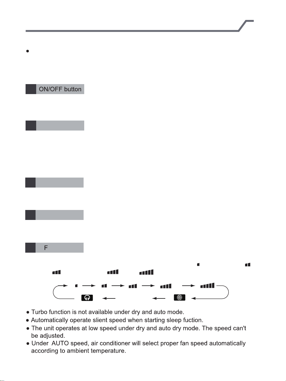
1 ON/OFF button
+/- button
2
Cool button
3
Heat button
4
Fan button
5
6 I FEEL button
up down swing button
7
8
Mode button
9
Left right swing button
10
T-ON/T-OFF button
11
Clock button
12
X-fan button
13
Air button
14
Light button
15
Sleep button
16
WIFI button
Introduction for icons on display screen
Set fan speed
Operation mode
Auto mode
Cool mode
Dry mode
Fan mode
Heat mode
Set time
Turbo fan speed
X-FAN function
Auto quiet mode
INTELLIGENT
HOUR ON OFF
Quiet mode
Temp. display type
:Set temp.
:Outdoor ambient temp.
WIFI
:Indoor ambient temp.
Send signal
battery power
humidity functions
Temp.display type
Healthy mode
Set temperature
Up & down swing
Left & right swing
46°F (8°C) heating function
child lock
I feel function
Replacing air
Sleep mode

Matching Remote Control
-7-
The RF remote control must be synchronized with air conditioner prior to use.
Follow the instructions below.
Note
Synch remote controls within 6.5ft (2m) from air conditioning unit.
While synching, the remote controller and air conditioner should be on standby
status.
Synching remote controller with air conditioner is a one-time requirement.
Programming remote control
. Press standy status on air conditioner.
. Stand near air conditioner while holding remote control. Press standby button on remote.
. Synching will occur automatically.
. If synch does not occur, move closer to unit and repeat steps.
REMOTE CONTROL FUNCTIONS
-8-
Note:
After the air conditioner has been properly installed, you can use the remote
control to operate the air conditioner. Press the power button on the remote
control. The green indicator light will display on the air conditioner unit.
Follow the instructions for using the remote control.
1
Use the ON/OFF remote button to turn on or turn off the air conditioner.
The button on the remote will display ON when the air conditioner is on.
+/- button
2
The +/- button increases or decreases the temperature setting on the air
conditioning unit. Hold the "+" or "-" for 2s to change the temperature setting.
NOTE: Temperature setting can not be adjusted in "auto mode".
Press the "+" or "-" for setting and adjusting TIMER.
Cool button
3
Press the Cool button to operate in cool mode.
Heat button
4
Press the Heat button to operate in heat mode.
5
Press the FAN button to adjust the fan circulation speed: low( ), low medium( ),
medium( ), medium high( ), high( ), super, auto and quiet.
Note:
AN button
Auto

REMOTE CONTROL FUNCTIONS
-9-
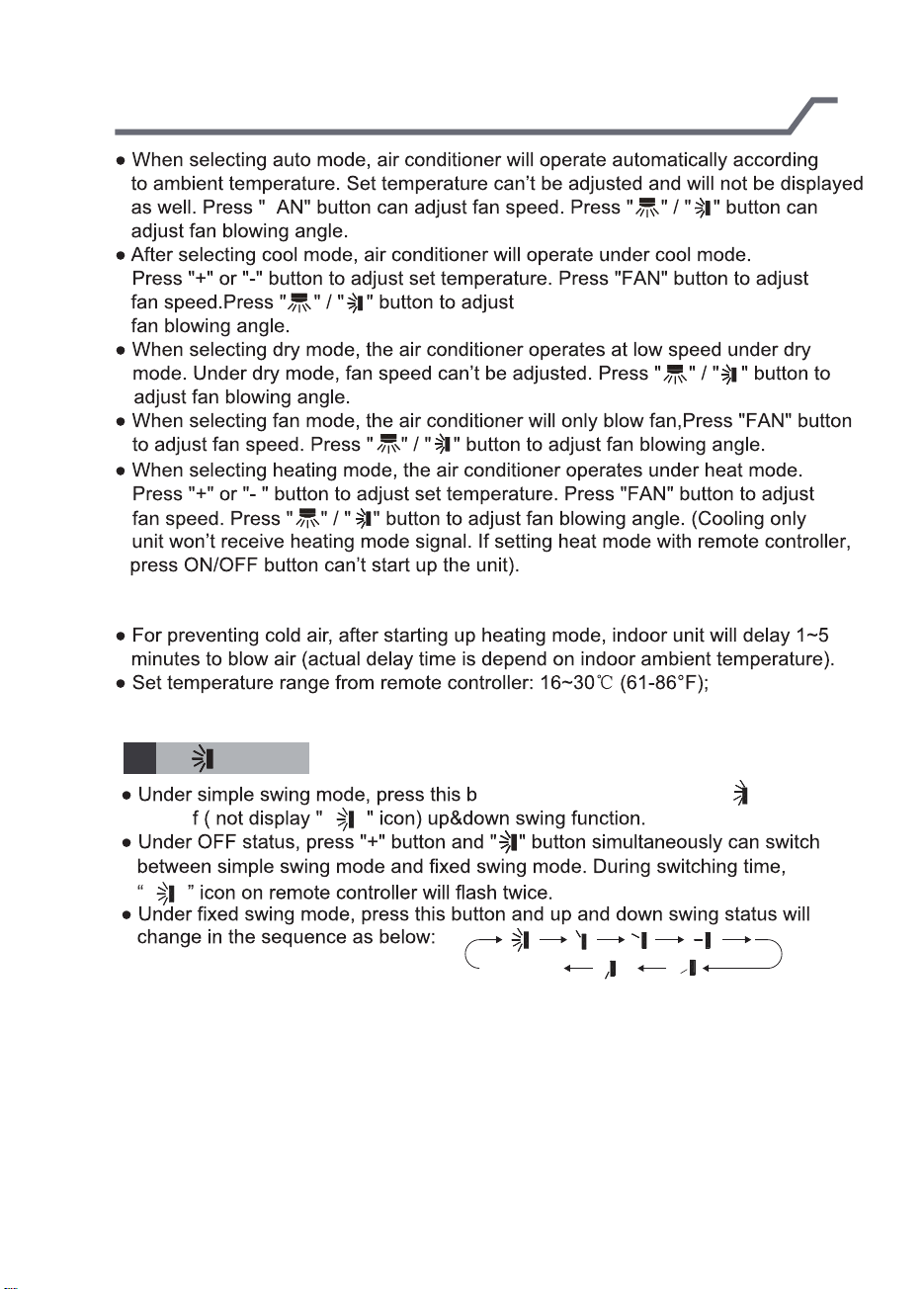
6
7
turn off ( not display " " icon) left&right swing function.
between simple swing mode and fixed swing mode. During switching time,
“ ” icon on remote controller will flash twice.
will change in the sequence as below:
EEL
L
.
.
button
utton can turn on (display " " icon ) or
neously can switch
no display
(stops at current position)
MODE button
8
Press this button to select your required operation mode.
T ANRY AT
REMOTE CONTROL FUNCTIONS
-10-
F
Note:
9
turn of
button
utton can turn on ( display " " icon) or
no display
(horizontal louvers stops
at current position)

REMOTE CONTROL FUNCTIONS
-11-
T-ON/T-OFF button
10
T-ON button
“T-ON” button can set the time for timer on. After pressing this button, " " icon
disappears and the word “ON" on remote controller blinks. Press “+” or “-”button
to adjust T-ON setting. After each pressing “+” or “-”button, T-ON setting will
increase or decrease 1min. Hold “+” or “-”button, 2s later, the time will change
quickly until reaching your required time. Press“T-ON”to confirm it. The word “ON”
will stop blinking. " " icon resumes displaying.Cancel TIMER ON: Under the
condition that T-ON is started up, press “T-ON” button to cancel it.
T-OFF button
“T-OFF” button can set the time for timer off. After pressing this button, " " icon
disappears and the word "OFF" on remote controller blinks. Press "+" or "-" button
to adjust T-OFF setting. After each pressing "+" or "-" button, T-OFF setting
will increase or decrease 1min. Hold "+" or "-" button, 2s later, the time will change
until reaching your required time. Press“T-OFF”to confirm it. The word “ON”will
"OFF" will stop blinking. " " icon resumes displaying. Cancel T-OFF.Under the
condition that T-OFF is started up, press “T-OFF” button to cancel it.
Note:
ff status, you can set T-OFF or T-ON simultaneously.
T-ON or T-OFF, please adjust the clock time.
After starting up T-ON or T-OFF, set the constant circulating valid. After that,
air conditioner will be turned on or turned off according to setting time. ON/OFF
button has no effect on setting. If you don’t need this function, please use remote
controller to cancel it.
CLOCK button
11
Press this button to set clock time. " " icon on remote controller will blink.
Press "+" or "-" button within 5s to set clock time. Each pressing of "+" or "-"
button, clock time will increase or decrease 1 minute. Hold "+" or "-" button, 2s
later, time will change quickly. Release this button when reaching your required
time. Press “CLOCK”button to confirm the time. " " icon stops blinking.
Note:
The interval between two operations can’t exceeds 5s. Otherwise, remote
controller will quit setting status. Operation for TIMER ON/TIMER OFF is
the same.
REMOTE CONTROL FUNCTIONS
-12-
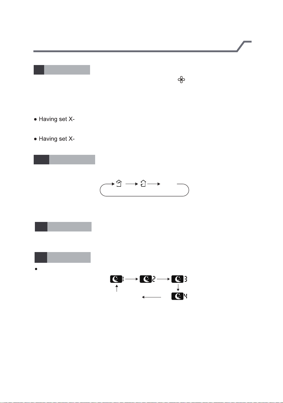
X-FAN button
12
Pressing this button in COOL or DRY mode, the icon " " is displayed and the
indoor fan will continue operation for 2 minutes in order to dry the indoor unit even
though you have turned off the unit. After energization, X-FAN OFF is defaulted.
X-FAN is not available inAUTO, FAN or HEAT mode.
This function indicates that moisture on evaporator of indoor unit will be blowed
after the unit is stopped to avoid mould.
FAN function on: After turning off the unit by pressing ON/OFF
button indoor fan will continue running for about 2 min. at low speed. In this
period, press X-FAN button to stop indoor fan directly.
FAN function off: After turning off the unit by pressing ON/OFF
button, the complete unit will be off directly.
Air button
13
Press this button to select your required operation mode.
cancel
Note:there is no this function for this unit. If press this button,the main unit will click,
but it also runs under original status.
LIGHT button
14
Pressing this button to turn off display light on indoor unit. Press this button again
to turn on display light.
SLEEP button
15
Pressing this button can select Sleep 1, Sleep 2,Sleep 3, Sleep 4 or cancel Sleep
circularly as below:
cancel

REMOTE CONTROL FUNCTIONS
-13-
In Sleep 1 and Sleep 2, the air conditioner will run according to a group of presetting
temperature curves.
Sleep 3 - the sleep curve setting under DIY Sleep mode:
(1) Under Sleep 3 mode, long press "AIR" button, the remote controller will enter
the setting of personalized sleep. In this case, the timer zone of remote controller
will display "1 hr" and the set temperature zone "88" will display the corresponding
temperature of the last set sleep curve and blink (The first entering will display
according to the initial curve setting value of manufacturer);
(2) Press "+" and "-" button to adjust the corresponding temperature. After adjusting,
press "AIR" button to confirm it;
(3) At this time, the timer time on the remote controller will increase automatically by
1hr (that is "2 hr" or "3 hr" … or "8 hr"). The set temperature zone "88" will display the
corresponding temperature of the last set sleep curve and blink;
(4)Repeat step(2) and step (3) until 8-hour temperature setting is finished, then the
sleep curve is set successfully. After that, remote controller will resume displaying the
original timer time and temperature zone will resume displaying the original set
temperature.
Sleep 3 - the sleep curve inquiry under DIY Sleep mode:
User can inquire the set sleep curve according to the setting method of sleep curve.
Enter the setting of personalized sleep but do not change the temperature. Then
press "AIR" button to confirm the setting.
Note: In the above setting or inquiry procedure, if there is no button pressing within
10s, remote controller will automatically exit the sleep curve setting and resume the
HEATING button is pressed during the setting or inquiry procedure, remote controller
original display. If ON/OFF, MODE, TIMER, HUMIDIFY, SLEEP, COOLING or
will also exit the sleep curve setting.
Sleep 4 is Siesta mode. The set temperature will change automatically according to
the features of siesta.
Sleep function will be disabled if the air condition is restarted after power failure;
when sleep function is turned on, quite fan speed will be also turned on.
Sleep function can not be set in AUTO mode.
Wifi button
16
Press this button 3s can set wifi function on or OFF.
At OFF status,press mode button and wifi button,can reset wifi mode parameter.
and open wifi function.

REMOTE CONTROL FUNCTIONS -
-14-
COMBINATION KEYS
X-FAN
This function indicates moisture levels will blow away after unit stops to prevent mold.
1.When X-FAN function is on: Press ON/OFF button (on remote) to turn off the unit.
The indoor fan will run for approximately 2 minutes at low speed. Press X FAN button
to stop indoor fan.
2. When X-FAN function is off: Press ON/OFF button (on remote) to turn off complete unit.
Auto Run
The Auto Run mode automatically adjusts to the room's temperature. The LCD on the
unit does not show the temperature.
Lock
Press "+" and "-" buttons simultaneously to lock or unlock the remote control. If remote
control is locked, the icon will display; when this occurs press any button on the
remote three times. The lock will disappear. If the remote is not locked, the lock
will not appear.
Fahrenheit & Centigrade
Make sure the remote control is off. Press MODE and press "C" or "F" to switch between
fahrenheit and centigrade.

Operating unit
-15-
After initializing unit, press the ON/OFF button on remote control to turn on air
1.
conditioner.
Press "MODE" on remote control to select mode: AUTO, COOL, DRY, FAN, or
2.
HEAT.
Press "+" or " - " button to set temperature. (Temperature can’t be adjusted
3.
under auto mode).
Press "FAN" button to set fan speed: low, low medium, medium, medium high,
4.
high, super, auto and quiet speed.
Press "SWING" button to select fan blowing angle.
5.
Replace batteries in remote control
1. Press the back side of remote control marked
the cover of battery box along the arrow direction.
signal sender battery
reinstall
2. Replace two AAA 1.5V dry batteries, and make
sure the position of "+" polar and "-" polar are
correct.
3. Reinstall the cover of battery box.
Battery level will be displayed on the remote
controller.When " " is flickering, please
Cover of battery box
o
F
replace the batteries, otherwise, remote
controller can’t operate normally.
NOTICE
ntrol signal sender at the receiving
window on indoor unit.
The distance between signal sender and receiving window should be no
more than 26ft(8m), and there should be no obstacles between them.
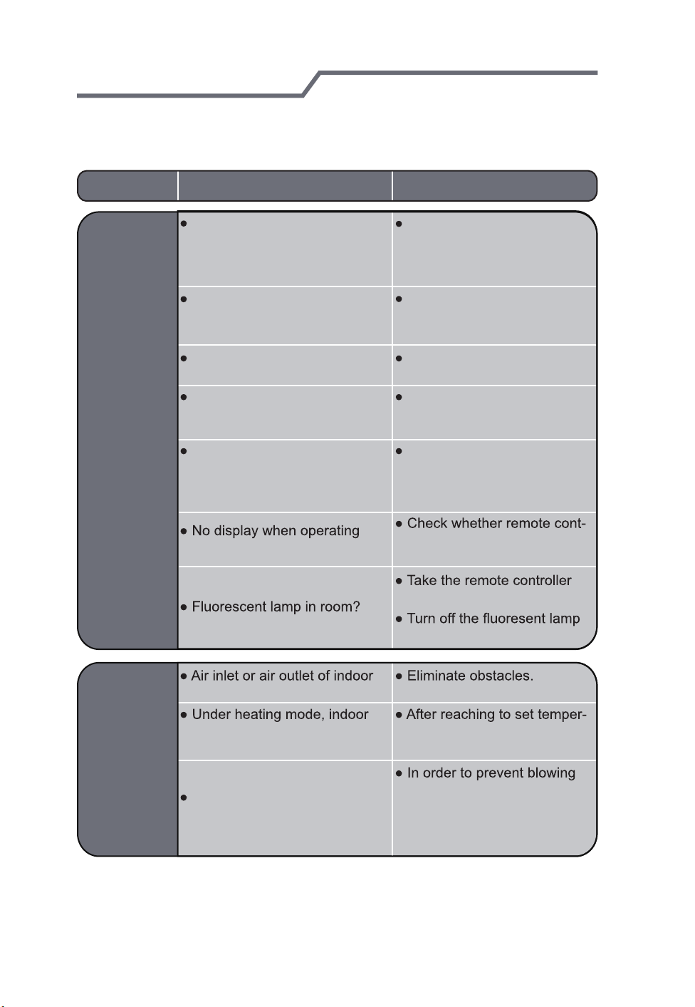
Signal may be interfered by a fluorescent lamp or wireless telephone;
remote control should be close to indoor unit during operation.
remove
battery level
batteries.
batteries.
remove
s no display, please
replace

Lost or damaged remote control
-16-
If the remote control is lost or damaged, the air conditioner can be turned
off directly from the unit. Lift the display panel on top of the air conditioner,
then press the AUX button to turn on or turn off the air conditioner. If the
air conditioner is on, it will operate through the AUTO MODE.
air conditioner. When the air conditioner is turned on, it will operate in auto
mode.
panel
Display panel
Warning:Use insulated object
to press the auto button
aux. button
CLEANING AND MAINTENANCE
WARNING
Turn off the air conditioner and disconnect the power before cleaning the air
conditioner to avoid electric shock.
r.
Clean surface of indoor unit
When the surface of indoor unit is dirty, it is recommended to use a soft dry cloth
or wet cloth to wipe it.
NOTICE:

CLEANING AND MAINTENANCE
-17-
Open panel
1
2
3
113°F (45°C)
.
WARNING
Clean filter every three months. If dust accumulates quickly, clean filter more
frequently.
4
.

CLEANING AND MAINTENANCE
-18-
Preparing to clean filter
1. Check whether air inlets and air outlets are blocked.
2. Check whether air switch, plug and socket are in good condition.
4. Check whether mounting bracket for outdoor unit is damaged or corroded.
If yes, please contact dealer.
5. Check whether drainage pipe is damaged.
Cleaning unit panel and filter
1. Disconnect power supply.
3. Check whether mounting bracket for outdoor unit is damaged or corroded.
If yes, please contact dealer.
Notice for recovery
1. Many packing materials are recyclable materials.
Please dispose them in appropriate recycling unit.
2. To dispose the air conditioner,please contact local dealer or consultant
service center for the correct disposal method.
Troubleshooting
-19-
Please identify problems and possible solutions for requesting maintenance
assistance. If problem can not be resolved by following the steps described,
contact your dealer or a qualified professional.
Problem Possible cause Solution
Indoor unit
can’t receive
remote
control's
signal or
remote
control
has no
action.
Determine if interference has
occurred due to severe static
electricity or voltage surge.
Determine if the remote control
is within the signal receiving
range.
Determine if other obstacles
are preventing signal receptivity.
Unit not responding to the
remote control.
Determine if remote control is
working properly. Possible
problems: low sensitivity,
fuzzy display or no display.
remote controller?
Remove the plug from the wall
outlet. Wait three minutes.
Reinsert the plug into the
outlet, then turn the unit on.
Make sure the remote control is
within the receiving range:
26.2ft(8m).
Eliminate possible obstacles that
can block signal reception.
Select proper angle and point
the remote controller at the re ceiving window on indoor unit.
Replace batteries if remote
control performs slowly or
poorly.
roller appears to be damaged.
If yes, replace it.
close to indoor unit.
and then try it again.
Air conditioner
unit does not
release air.
unit is blocked?
temperature is reached to set
temperature?
Heating Mode not starting right
after setting it in the remote
control.
ature, indoor unit will stop bl owing out air.
out cold air, indoor unit will be
started after delaying for sev eral minutes, which is a nor mal phenomenon.

Troubleshooting
-20-
Problems Possible Causes Solutions
Air conditioner does
not start.
Mist is coming
out of indoor
unit's air outlet.
Set temperature can’t
be adjusted.
burnt out?
after stopping operation?
Is remote control function
setting correct?
idity is high?
mode?
exceeds the set temperature
range?
air switch or fuse.
on the unit again.
Occurs if indoor air rapidly cools
down.
temperature and humidity will
be decrease and mist will
disappear.
sted under auto mode.
Please switch the operation
mode if you need to adjust
temperature.
16 ~30 .
After a while, indoor
Cooling or
heating is
inaccurate.
resumes normal.
range? range.

Troubleshooting
-21-
Problems Possible causes Solutions
Sources of foul odors: furniture,
Foul odors
cigarettes, etc.
Air conditioner
suddenly
operates normally
without repair
Outdoor
unit has
vapor
“Water
noise
Cracking
noise
Occurs when there's
interference: thunder, wireless
devices, etc.
Air conditioner unexpectedly
turns on or off and emits an
unfamiliar sound.
The air conditioner makes an
unusual cracking sound.
power, and then turn on the
unit again.
ating mode, it may generate
vapor
the unit, which is a normal
phenomenon.
caused by expansion and/or
contraction of panel or other
parts due to the change of
temperature.
, which is a normal
occurence.
Troubleshooting
-22-
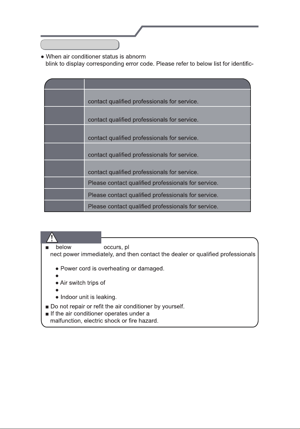
Error Codes
ation of error code.
al, temperature indictor on indoor unit will
Error code
E5
E6
E8
U8
H6
C5
F1
F2
Note: If there are other error codes, please contact qualified professionals for
service.
It can be eliminated after restarting the unit. If not,
It can be eliminated after restarting the unit. If not,
It can be eliminated after restarting the unit. If not,
It can be eliminated after restarting the unit. If not,
It can be eliminated after restarting the unit. If not,
Troubleshooting
WARNING
If incidences
ease turn off air conditioner and discon-
for service.
There’s abnormal sound during operation.
f frequently.
Air conditioner gives off burning smell.
bnormal conditions, it may cause
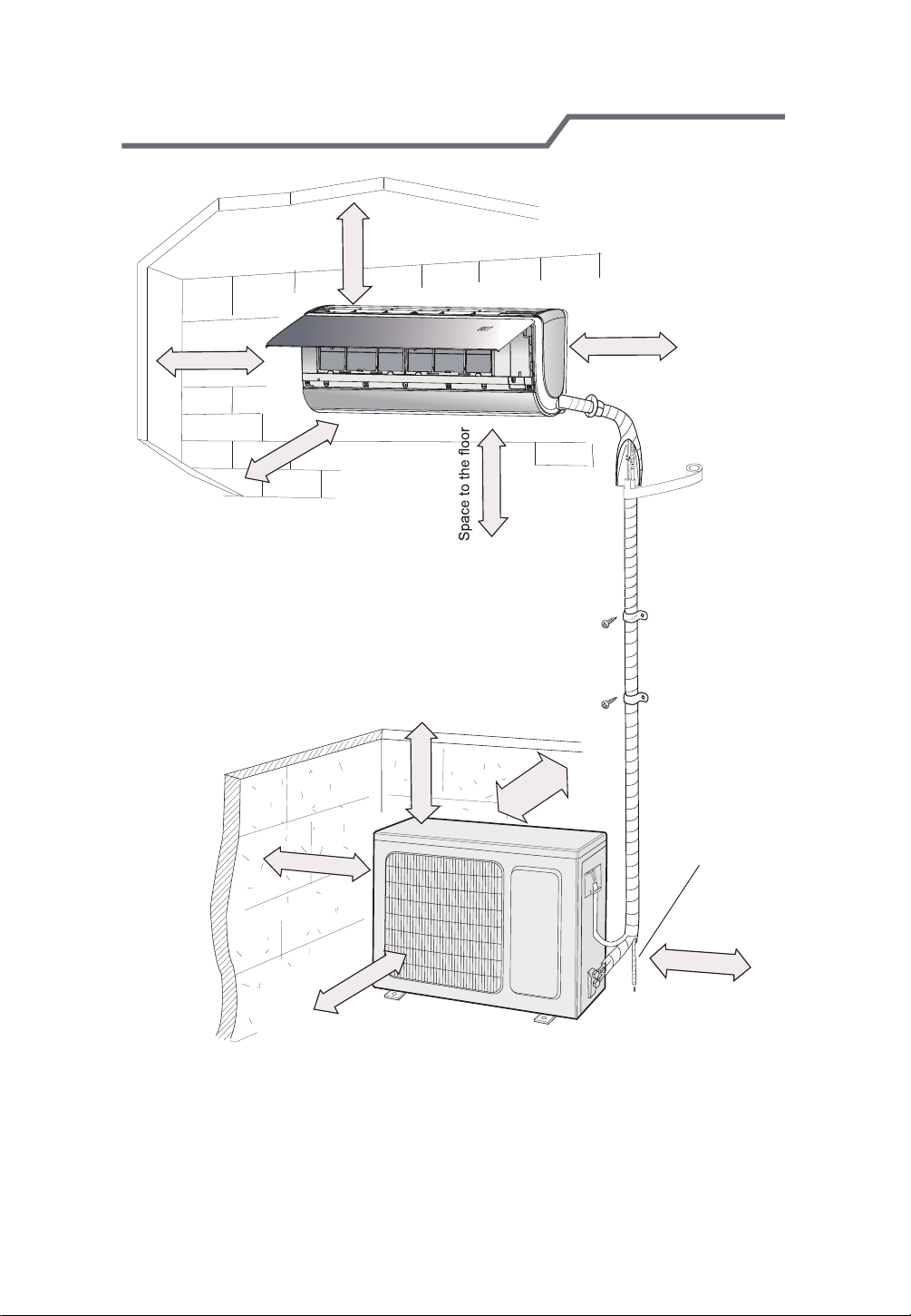
Installation diagram
-23-
At least 4.9 ft (15cm)
Space to the ceiling
At least 0.49ft (15cm)
Space to the wall
At least 9.8 ft (300cm)
Space to the wall
At least 0.49 ft (15cm)
Space to the obstruction
At least 0.98 ft (30cm)
Space to the wall
At least 6.56 ft (200cm)
Space to the obstruction
At least 8.2 ft (250cm)
Space to the
obstruction
Space to the obstruction
At least 1.64 ft (50cm)
At least
0.98 ft (30cm)
Drainage pipe
At least 1.64ft (50cm)
Space to the
obstruction
Tools for installation
-24-
1 Level meter 2 Screw driver 3 Impact drill
4 Drill head 5 Pipe expander 6 Torque wrench
7 Open-end wrench 8 Pipe cutter 9 Leakage detector
10 Vacuum pump 11 Pressure meter 12 Universal meter
13 Inner hexagon spanner 14 Measuring tape
Note:
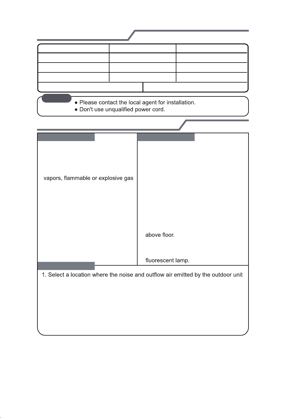
INSTALLATION TIPS
Basic requirement
Installing the unit in the following places may cause malfunction. If it is unavoidable, please consult the local
dealer:
1.The place with strong heat sources,
,
or volatile objects spread in the air.
2.The place with high-frequency
devices (such as welding machine,
medical equipment).
3.The place near coast area.
4.
The place with oil or fumes in the air.
5.The place with sulfureted gas.
6.Other places with special circums-
tances.
7.The appliance shall not be installed
in the laundry.
Outdoor unit
will not affect neighborhood.
2. The location should be well ventilated and dry, so the outdoor unit
won't be exposed directly to sunlight or strong wind.
3. The location should be able to withstand the weight of outdoor unit.
4. Make sure that the installation follows the requirement of installation
dimension diagram.
5. Select a location which is out of reach for children and far away from animals
or plants. If it is unavoidable, please add the fence for safety purpose.
Indoor unit
1. There should be no obstruction near air
inlet and air outlet.
2. Select a location where the condensat ion water can be dispersed easily and
won't affect other people.
3. Select a location which is convenient to
connect the outdoor unit and near the
power socket.
4. Select a location which is out of reach
for children.
The location should be able to withstand
5.
the weight of indoor unit and won't incr ease noise and vibration.
6.
The appliance must be installed 2.5m
7. Don't install the indoor unit right above
the electric appliance.
8. Please try your best to keep way from

Grounding requirement
-25-
The Air conditioner must be properly grounded to avoid electric shock.
2. The yellow-green wire in air conditioner is grounding wire, which can't be used
for other purposes.
3. The grounding resistance should comply with national electric safety regulations.
4. The appliance must be positioned so that the plug is accessible.
5. An all-pole disconnection switch having a contact separation of at least 1/8 in (3mm)
in
sure the plug is within reach after installation;
6. Including an air switch with suitable capacity, please note the following table. Air
switch should be included magnet buckle and heating buckle function, it can
protect the circuit-short and overload. (Caution: please do not use the fuse only
for protect the circuit)
For models with a power plug, make
Air-conditioner
09K
12K
18K
Air switch capacity
15A
20A
30A
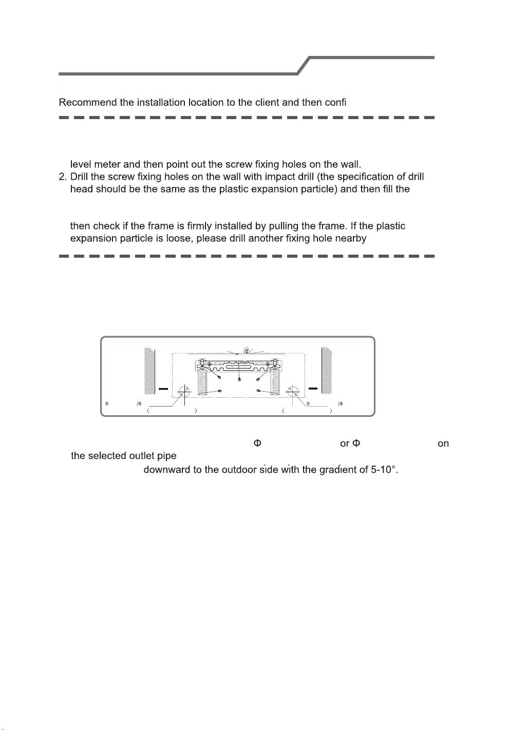
INDOOR UNIT INSTALLATION
-26-
Step one: choosing installation location
rm it with the client.
Step two: install wall-mounting frame
1. Hang the wall-mounting frame on the wall; adjust it in horizontal position with the
plastic expansion particles in the holes.
3. Fix the wall-mounting frame on the wall with tapping screws (ST4.2X25TA) and
.
Step three: open piping hole
1. Choose the position of piping hole according to the direction of outlet pipe. The
position of piping hole should be a little lower than the wall-mounted frame,
shown as below.
Wall
2 1/6 in (55mm) 2 3/4 in (70mm) 2 1/6 in (55mm) 2 3/4 in (70mm)
Mark in the middle of it
Space
to the
wall
above
5 9/10 in
(150mm)
Left
Rear piping hole
Level meter
Rear piping hole
Wall
Space
to the
wall
above
5 9/10 in
(150mm)
Right
2. Open a piping hole with the diameter of 2 1/6 in (55mm) 2 3/4 in (70mm)
position.In order to drain smoothly, slant the piping hole on
the wall slightly

INDOOR UNIT INSTALLATION
-27-
Note:
opening the hole.
The plastic expansion particles are
locally.
Step four: outlet pipe
1. The pipe can be led out in the
direction of right, rear right, left or
rear left.
rear left
right
rear right
left
Indoor
5-10
2. When select leading out the pipe
from left or right, please cut off the
corresponding hole on the bottom
case.
left
outdoor
2 1/6 in (55mm)
2 3/4 in (70mm)
right
cut off
the hole
/
1. Aim the pipe joint at the corresponding
bellmouth.
union nutpipe joint
2. Pretightening the union nut with hand.
3. Adjust the torque force by referring to the following sheet. Place the open-end
wrench on the pipe joint and place the torque wrench on the union nut. Tighten
the union nut with torque wrench.
pipe
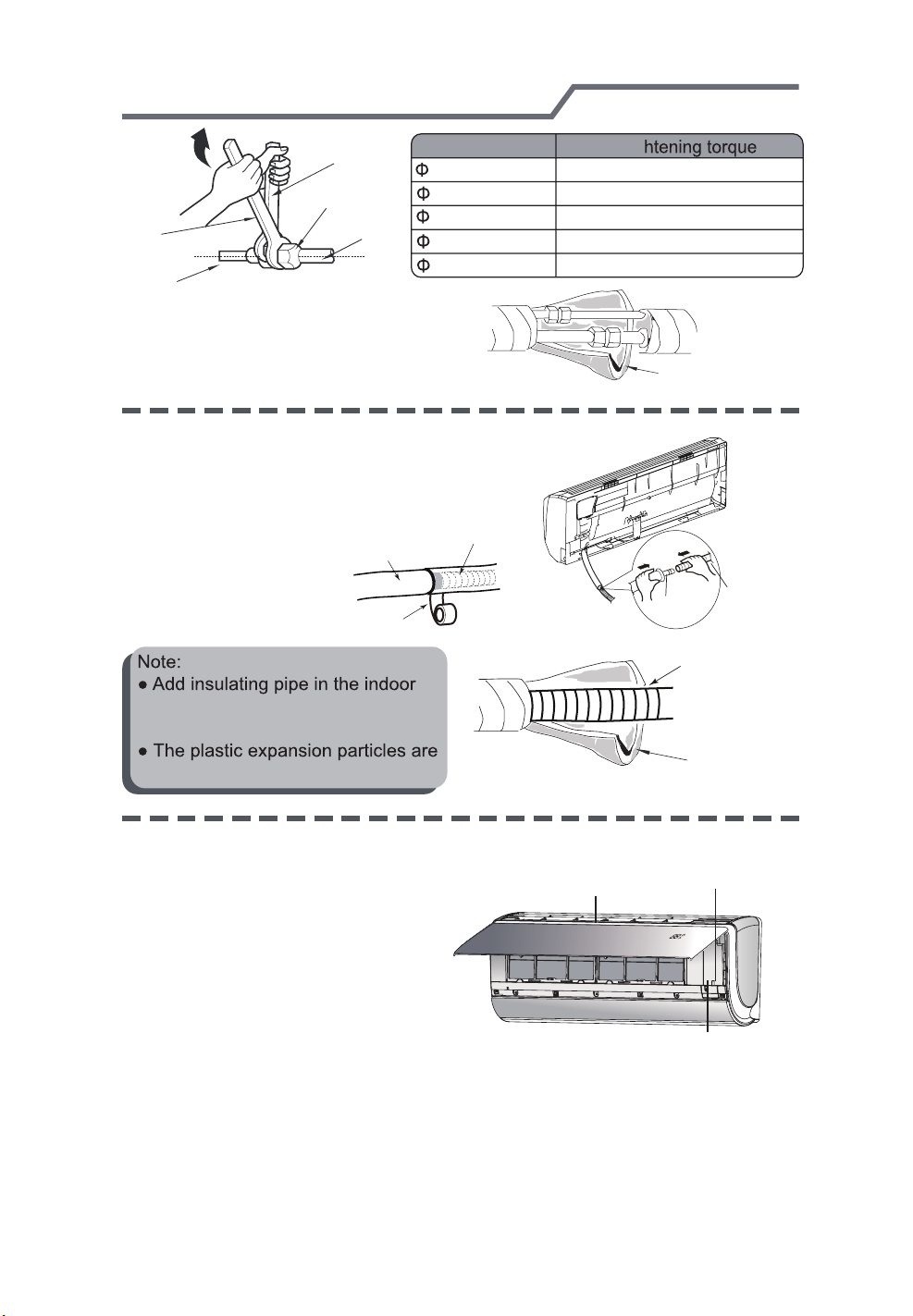
INDOOR UNIT INSTALLATION
-28-
open-end
wrench
union nut
Hex nut diameter Tig
1/4 in (6 mm)
3/8 in (9.52 mm)
1/2 in (12 mm)
torque wrench
pipe
5/8 in (16 mm)
3/4 in (19 mm)
indoor pipe
4. Wrap the indoor pipe and joint of con nection pipe with insulating pipe, and
then wrap it with tape.
Step six: install drain hose
1. Connect the drain hose to the outlet pipe of
indoor unit.
drain hose
2. Bind the joint with tape.
outlet pipe
tape
20.34~27.12 ft.lb(15~20 N.m)
40.68~54.24 ft.lb(30~40 N.m)
61.02~74.58 ft.lb(45~55 N.m)
81.36~88.14 ft.lb(60~65 N.m)
94.93~101.7 ft.lb(70~75 N.m)
insulating pipe
outlet
pipe
drain hose
drain hose
drain hose in order to prevent
condensation.
not provided.
Step seven: connect wire of indoor unit
1. Open the panel, remove the screw
on the wiring cover and then take
down the cover.
pane
insulating pipe
screw
wiring cover

INDOOR UNIT INSTALLATION
-29-
2. Make the power connection wire go
through the cable-cross hole at the back
cable-cross
hole
the front side.
power connection
wire
with wire clip.After finishing wiring
into the wire-crossing groove as shown in the following figure, in order to avoid
pressing the wire when closing the electric box cover.
L2’
S
L1’
green
red
black
white
(blue)
Outdoor unit connection
(brown)
(yellow-
green)
4.Put wiring cover back and then tighten the screw
5.Close the panel.
Note:
All wires of indoor unit and outdoor uni
t should be connected by a professional.
If the length of power connection wire is insufficient, please contact the supplier
for a new one. Avoid extending the wire by yourself.
For the air conditioner with plug, the plug should be reachable after finishing
installation.
The air switch should be all-pole parting and the contact parting distance should
2/17 in (3mm)
INDOOR UNIT INSTALLATION
-30-
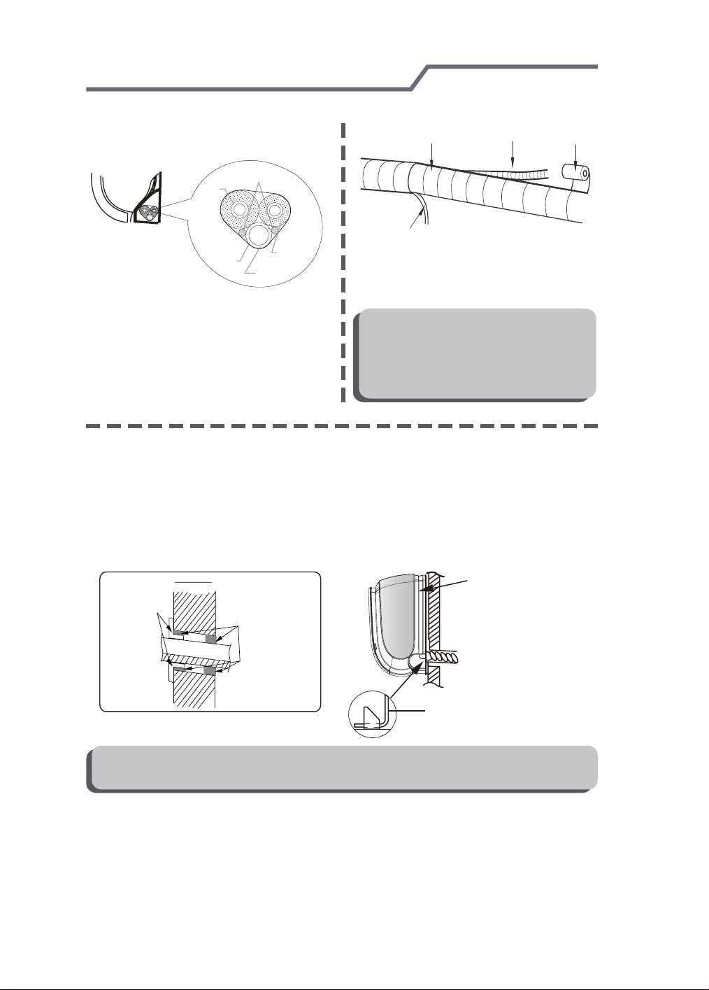
Step eight: bind up pipe
1. Bind up the connection pipe, power
connection pipe
cord and drain hose with the band.
indoor and
indoor unit
2. Reserve a certain length of drain
hose and power cord for installation
when binding them. When binding to
a certain degree, separate the indoor
power and then separate the drain
hose.
outdoor power cord
gas
pipe
band
liquid pipe
drain hose
indoor power cord
3. Bind them evenly.
4. The liquid pipe and gas pipe should
be bound separately at the end.
1RWH
Ɣ7KHSRZHUFRUGDQGFRQWUROZLUH
FDQWEHFURVVHGRUZLQGLQJ
Ɣ7KHGUDLQKRVHVKRXOGEHERXQG
at the bottom.
Step nine: hang the indoor unit
1. Put the bound pipes in the wall pipe and then make them pass through the wall
hole.
2. Hang the indoor unit on the wall-mounting frame.
3. Stuff the gap between pipes and wall hole with sealing gum.
4. Fix the wall pipe.
5.Check if the indoor unit is installed firmly and closed to the wall.
indoor
outdoor
drain hose
upper hook
band
wall pipe
sealing gum
lower hook of
wall-mounting frame
1RWH
Ɣ'RQRWEHQGWKHGUDLQKRVHWRRH[FHVVLYHO\LQRUGHUWRSUHYHQWEORFNLQJ

CAUTION NOTE
-31-
!
EQUIPMENT DAMAGE HAZARD
Failure to follow this caution may result in equipment damage or improper operation.
In regions with snowfall and cold temperatures, avoid installing the outdoor unit in areas where it can
be covered by snow. If the outdoor unit is installed in areas where heavy snow is expected, a field
supplied ice or snow stand and/or field supplied--installed wind baffle should be installed to protect the
unit from snow accumulation and/or blocked air intake. Blocking the air intake may result in reduced
airflow, significantly reduced performance and damage to the equipment.
CAUTION
OUTDOOR UNIT INSTALLATION FOR SINGLE ZONE APLICATIONS
(REFER TO THE 38GJ OWNER'S MANUAL FOR MULTIZONE)
(select it according to the actual installation situation)
1. Select installation location according to the house structure.
2. Fix the support of outdoor unit on the selected location with expansion screws.
3. Make sure the outdoor unit is mounted level and off the ground in areas where
there is snow.
Note:
installing the outdoor unit.
Make sure the support can withstand at least
four times of the unit weight.
1 1/6 in (3cm)
joint.
3 HP~
6 5/7 HP (2300W~5000W), 6 expansion
screws are needed;
for the unit with cooling capacity of 8 HP~
10 3/4 HP (6000W~8000W), 8 expansion
screws are needed;
for the unit with cooling capacity of 13 2/5 HP
~21 1/2 HP (10000W~16000W)
screws are needed.
,10 expansion
at least 1 1/6 in (3cm) above the floor
Step two: install drain joint
(Only for cooling and heating
unit)
1. Connect the outdoor drain joint into
the hole on the chassis, as shown in
the picture below.
2. Connect the drain hose into the drain
vent.
drain vent
Drain hose
chassis
outdoor drain joint
1. Place the outdoor unit on the
support.
2. Fix the foot holes of outdoor unit
with bolts.
foot holes
foot holes

OUTDOOR UNIT INSTALLATION FOR SINGLE ZONE APLICATIONS
-32-
(REFER TO THE 38GJ OWNER'S MANUAL FOR MULTIZONE)
Step four: connect indoor and outdoor pipes
1. Remove the screw on the right han dle of outdoor unit and then remove
the handle.
screw
handle
3. Pretightening the union nut with
hand.
pipe joint
union nut
2. Remove the screw cap of valve and
aim the pipe joint at the bellmouth of
pipe.
liquid pipe
liquid
gas pipe
valve
gas valve
4. Tighten the union nut with torque
wrench by referring to the sheet
below.
Hex nut diameter Tig
1/4 in (6 mm)
3/8 in (9.52 mm)
1/2 in (12 mm)
5/8 in (16 mm)
3/4 in (19 mm)
20.34~27.12 ft.lb(15~20 N.m)
40.68~54.24 ft.lb(30~40 N.m)
61.02~74.58 ft.lb(45~55 N.m)
81.36~88.14 ft.lb(60~65 N.m)
94.93~101.7 ft.lb(70~75 N.m)
1. Remove the wire clip; connect the po wer connection wire and signal control
wire (only for heating unit) to the wiring
terminal according to the
18K
L1’ S L2’
green
white
(yellow-
(blue)
green)
handle
black
Indoor unit connection
(brown)
L2
black
(brown)
L2
POWER
L1 G
whitered
(blue)
L1
green
(yellowgreen)
、12K
L1’
S
L1
Indoor unit
L2’ G
L2
L1
L2
G
OUTDOOR UNIT INSTALLATION FOR SINGLE ZONE APLICATIONS
-33-
(REFER TO THE 38GJ OWNER'S MANUAL FOR MULTIZONE)
2. Fix the power connection wire and signal control wire with wire clip (only for
cooling and heating unit).
1RWH
Ɣ$IWHUtighteningWKHVFUHZSXOOWKHSRZHUFRUGVOLJKWO\WRFKHFNLILWLV¿UP
Ɣ1HYHUFXWWKHSRZHUFRQQHFWLRQZLUHWRSURORQJRUVKRUWHQWKHGLVWDQFH
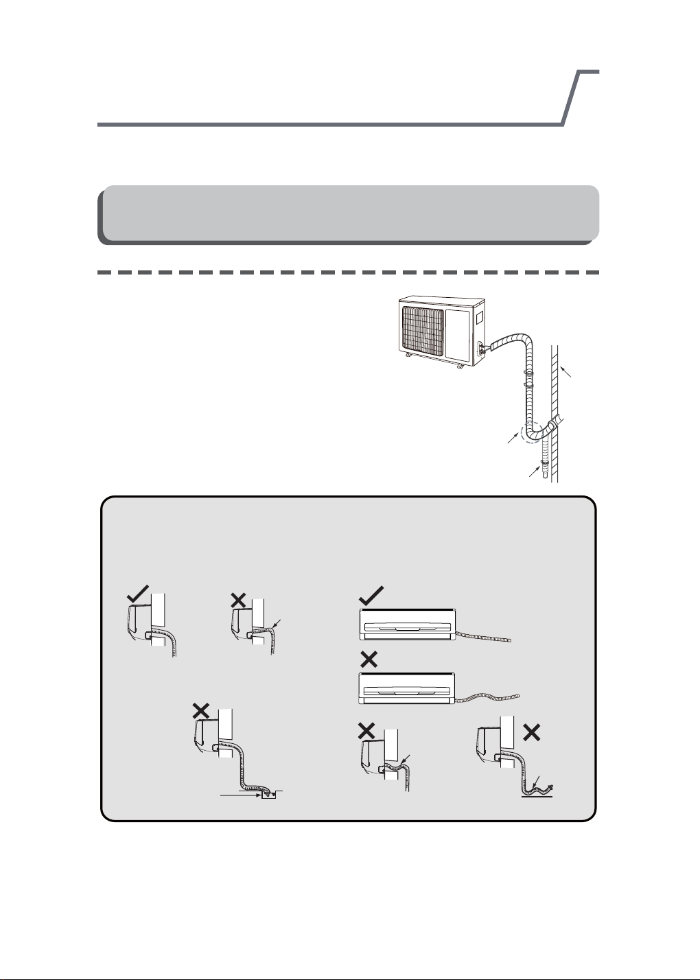
Step six: neaten the pipes
1. The pipes should be placed along the wall,
bent reasonably and hidden possibly. Min.
semidiameter of bending the pipe is 10cm.
2. If the outdoor unit is higher than the wall
hole, you must set a U-shaped curve in the
pipe before pipe goes into the room, in
order to prevent rain from getting into the
room.
U-shaped curve
drain hose
wall
Note:
Ɣ7KHWKURXJKZDOKHLJKWRIGUDLQKRVH
VKRXOGQWEHKLJKHUWKDQWKHRXWOHW
pipe hole of indoor unit.
the drain hose
can't raise
upwards.
Ɣ7KHZDWHURXWOHWFDQWEHSODFHG
in water in order to drain smoothly.
The water outlet
can't be placed
in water
Ɣ6ODQWWKHGUDLQKRVHVOLJKWO\GRZ
QZDUGV7KHGUDLQKRVHFDQWEH
FXUYHGUDLVHGDQGÀXFWXDQWHWF
The drain hose can't be fluctuant
The drain hose
can't be fluctuant
The water
outlet can't be
fluctuant

Vacuum pumping
-34-
Use vacuum pump
1. Remove the valve caps on
the liquid valve and gas
valve and the nut of refri gerant charging vent.
2. Connect the charging hose
RISLH]RPHWHUWRWKHUHIUL
gerant charging vent of gas
valve and then connect the
other charging hose to the
vacuum pump.
2SHQWKHSLH]RPHWHUFRP
pletely and operate for
10-15min to check if the
SUHVVXUHRISLH]RPHWHUUH
mains in -14.5 PSI (-0.1 MPa).
4. Close the vacuum pump
and maintain this status for
1-2min to check if the pres-
VXUHRISLH]RPHWHUUHPDLQV
in -14.5 PSI (-0.1 MPa). If the pressure decreases, there may be leakage.
5HPRYHWKHSLH]RPHWHURSHQWKHYDOYHFRUHRIOLTXLGYDOYHDQGJDVYDOYH
completely with inner hexagon spanner.
6. Tighten the screw caps of valves and refrigerant charging vent.
7. Reinstall the handle.
liquid valve
gas valve
refrigerant charging
vent
nut of refrigerant
charging vent
piezometer
valve cap
vacuum pump
inner hexagon
spanner
close
open
Lo Hi
Leakage detection
1. With leakage detector:
Check if there is leakage with leakage detector.
2. With soap water:
If leakage detector is not available, please use soap water for leakage detection.
Apply soap water at the suspected position and keep the soap water for more
than 3min. If there are air bubbles coming out of this position, there's a leakage.

Checking installation
-35-
Items to be checked Possible problem
The unit may drop, shake or emit noise.
Has the refrigerant leakage been
tested?
Is water drained well?
(heating) capacity.
It may cause condensation and water
dripping.
It may cause condensation and water
dripping.
Is the voltage of power supply according to the voltage marked on the
nameplate?
Is electric wiring and pipeline installed
correctly?
Is the unit grounded securely? It may cause electric leakage.
Is there any obstruction in the air inlet
and outlet?
The dust and sundries caused during
installation are removed?
The gas valve and liquid valve of
connection pipe are open completely?
It may cause malfunction or damaging
the parts.
It may cause malfunction or damaging
the parts.
It may cause malfunction or damaging
the parts.
(heating) capacity.
It may cause malfunction or damaging
the parts.
(heating) capacity.
Testing unit operation
1. Preparation of test operation
2. Method of test operation
operation.
whether the operation is normal or not.
60.8°F (16°C), the air conditioner can’t
start cooling.
Configuring connection pipe
-36-
1. Standard length of connection pipe
16.4 ft (5 m),24.6 ft (7.5 m),26.2 ft (8 m)
2.Min. length of connection pipe is 9.8 ft (3 m).
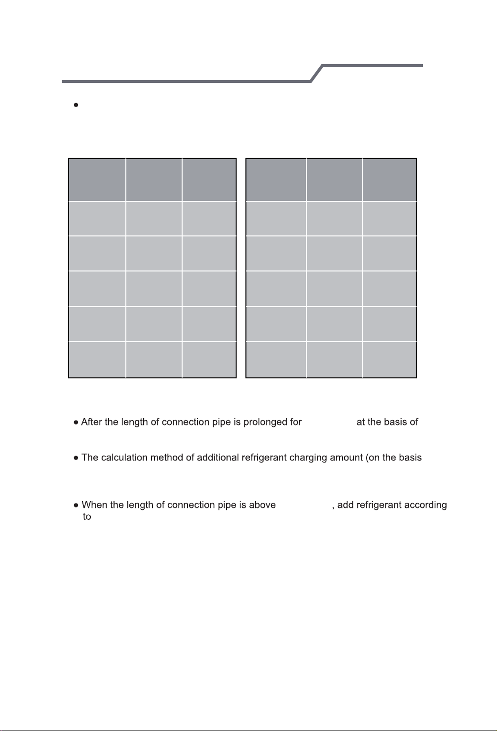
3.Max. length of connection pipe and max. high difference.
Cooling
capacity
5000Btu/h
(1465W)
7000Btu/h
(2051W)
9000Btu/h
(2637W)
12000Btu/h
(3516W)
18000Btu/h
(5274W)
4. The additional refrigerant oil and refrigerant charging required after prolonging
connection pipe
standard length, you should add 1/3 in³ (5 ml) of refrigerant oil for each additional
16.4 ft (5 m)
Max length
of connection pipe
49.2 ft (15 m)
49.2 ft (15 m)
49.2 ft (15 m)
65.6 ft (20 m)
82 ft (25 m)
of connection pipe.
Max height
difference
16.4 ft (5 m)
16.4 ft (5 m)
16.4 ft (5 m)
Cooling
capacity
24000Btu/h
(7032W)
28000Btu/h
(8204W)
36000Btu/h
(10548W)
42000Btu/h
(12306W)
48000Btu/h
(14064W)
Max length
of connection pipe
82 ft (25 m)
98.4 ft (30 m)
98.4 ft (30 m)
98.4 ft (30 m)32.8 ft (10 m)
98.4 ft (30 m)32.8 ft (10 m)
32.8 ft (10m)
Max height
difference
32.8 ft (10 m)
32.8 ft (10 m)
65.6 ft (20 m)
65.6 ft (20 m)
65.6 ft (20 m)
of liquid pipe):
Additional refrigerant charging amount = prolonged length of liquid pipe ×
additional refrigerant charging amount per meter
16.4 ft (5 m)
the prolonged length of liquid pipe. The additional refrigerant charging amount
per meter is different according to the diameter of liquid pipe. See the
following sheet.
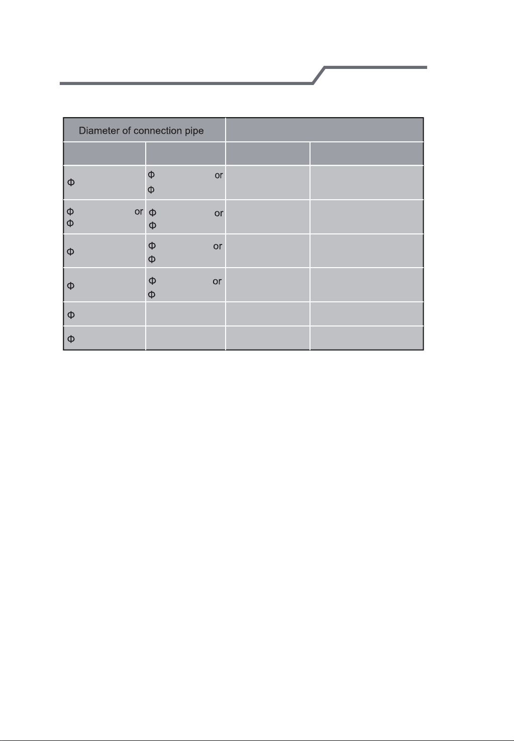
Configuring connection pipe
-37-
Additional refrigerant charging amount for R410A
Outdoor unit throttle
Liquid pipe(in/mm) Gas pipe(in/mm)
1/4 in (6 mm)
1/4 in (6 mm)
3/8 in (9.52 mm)
1/2 in (12 mm)
5/8 in (16 mm)
3/4 in (19 mm)
7/8 in (22.2 mm)
3/8 in (9.52 mm)
1/2 in (12 mm)
5/8 in (16 mm)
3/4 in (19 mm)
3/4 in (19 mm)
7/8 in (22.2 mm)
1 in (25.4 mm)
1 1/4 in (31.8mm)
_
_
Cooling only(oz/ft (g/m)) Cooling and heating(oz/ft (g/m))
0.2 oz/ft (15 g/m)
0.2 oz/ft (15 g/m)
0.3 oz/ft (30 g/m)
0.6 oz/ft (60 g/m)
2.7 oz/ft (250 g/m)
3.8 oz/ft (350 g/m)
0.2 oz/ft (20 g/m)
0.5 oz/ft (50 g/m)
1.3 oz/ft (120 g/m)
1.3 oz/ft (120 g/m)
2.7 oz/ft (250 g/m)
3.8 oz/ft (350 g/m)

Pipe expanding method
-38-
Note:
Improper pipe expanding is the main cause of refrigerant leakage. Please expand
the pipe according to the following steps:
A: Cut the pipe
E: Expand the port
the distance of indoor unit and
outdoor unit.
pipe
pipe cutter
leaning uneven burr
B: Remove the burrs
prevent the burrs from getting into
the pipe.
pipe
shaper
downwards
hard
expander
mold
pipe
diameter, please refer to the sheet
below:
Outer diameter
(mm (in ))
A(in/mm)
Max Min
1/20 in (1.3 mm) 0.02 in (0.7 mm)
3/50 in (1.6 mm) 1/24 in (1 mm)
0.07 in (1.8 mm)
1/10 in (2.4 mm)
1/24 in (1 mm)
2/25 in (2.2 mm)
F: Inspection
C: Put on suitable insulating pipe
connection pipe and outdoor valve;
install the union nut on the pipe.
union pipe
pipe
If there is any blemish, expand the
port again according to the steps
above.
smooth surface
improper expanding
damaged
leaning
the length is equal
surface
crack uneven
thickness


66129916984
Copyright 2014 Ca rrier Corporation S 7310 W. Morris St. S Indianapolis, IN 46231
Manufacturer reserves the right to change, at any time, specifications and designs without notice and without obligations.
Edition Date: 11/14
Catalog No: 38-40GR-01OM
Replaces: New
 Loading...