

Page 1
r«) 11 w<0 11
Carrier Corporation • Syracuse, N.Y. 13221
Fan Sections and Accessory Electric Heaters
CONTENTS
SAFETY CONSIDERATIONS
MODULAR SYSTEM
INTRODUCTION..................................................2,3
INSTALLATION...................................................3-9
Step 1 — Inspect Equipment
Step 2 — Determine Position of Unit by
Airflow Direction.................................................. 3
Step 3 — Assemble Required Unit
Step 4 — Connect Ductwork to Unit
Supply and Return Air Openings
Step 5 — Insulate Ductwork
Step 6 — Install Accessory Cooling
Control Kit (cooling-only applications) ... 9
Step 7 — Install Accessory Humidity
Control Kit (28TQ applications only)
ELECTRICAL DATA AND WIRING ..................9-16
Step 8 — Install Branch Circuit
Disconnect Switch(es) per NEC .........................9
Step 9 — Route Line Power Leads
into Unit
................................................................
Step 10 — Connect Ground Leads
Step 11 — Set Fan Motor Speed(s)
Step 12 — Connect Control Power
Wiring (24-v)
.......................................................
START-UP........................................................... 16
FAN SECTION SERVICE
ELECTRIC HEATER SERVICE.......................... 17
^ Table 1 — Physical Data and Dimensions
MODEL 40FS
OPERATING WT (lb) 60 65 72
FAN
Rpm, 60 Hz
Air Discharge
Nominal Cfm
PSC Motor — Hp
DIMENSIONS (ft-in.)
Length A
Width B
Height C
DUCT INLET (ft-in.)
DUCT OUTLET (ft-in.)
FILTER (1-in. thick)*
No.
Size (in.)
PSC — Permanent Split Capacitor
*40FS units factory equipped with permanent fi Iter and reversible rack with
s/s-in. duct connection flange.
075 1 120 ! 160 200 220
625-800
(2-speed)
Upflow-
Horizontal
750
Mo
2-0’Me
D
E
F
G
...........................
..............................
...................
.....................
................................
..................
..................
..................
...................................
(Fig. 1)
Centrifuga
(1-speed)
Upflow
l-llMe
— Direct Dr
1-9%
-lOMe
-
7%
1-7
1-178
1
800
(3-s
Upflow-[
Hori
1250
Vi
1-7%
975
1150
1
1
0-97s
21x24V4 I 21x203/4 | 21x24V4
ve
-1100
peed)
lownflowzontal
1750 1 2000
9,10
% 1 1
2-0’Me
1-11’/Í6
I
Page
. 2
3
3-7
7,8
8
9
9
10
10
17
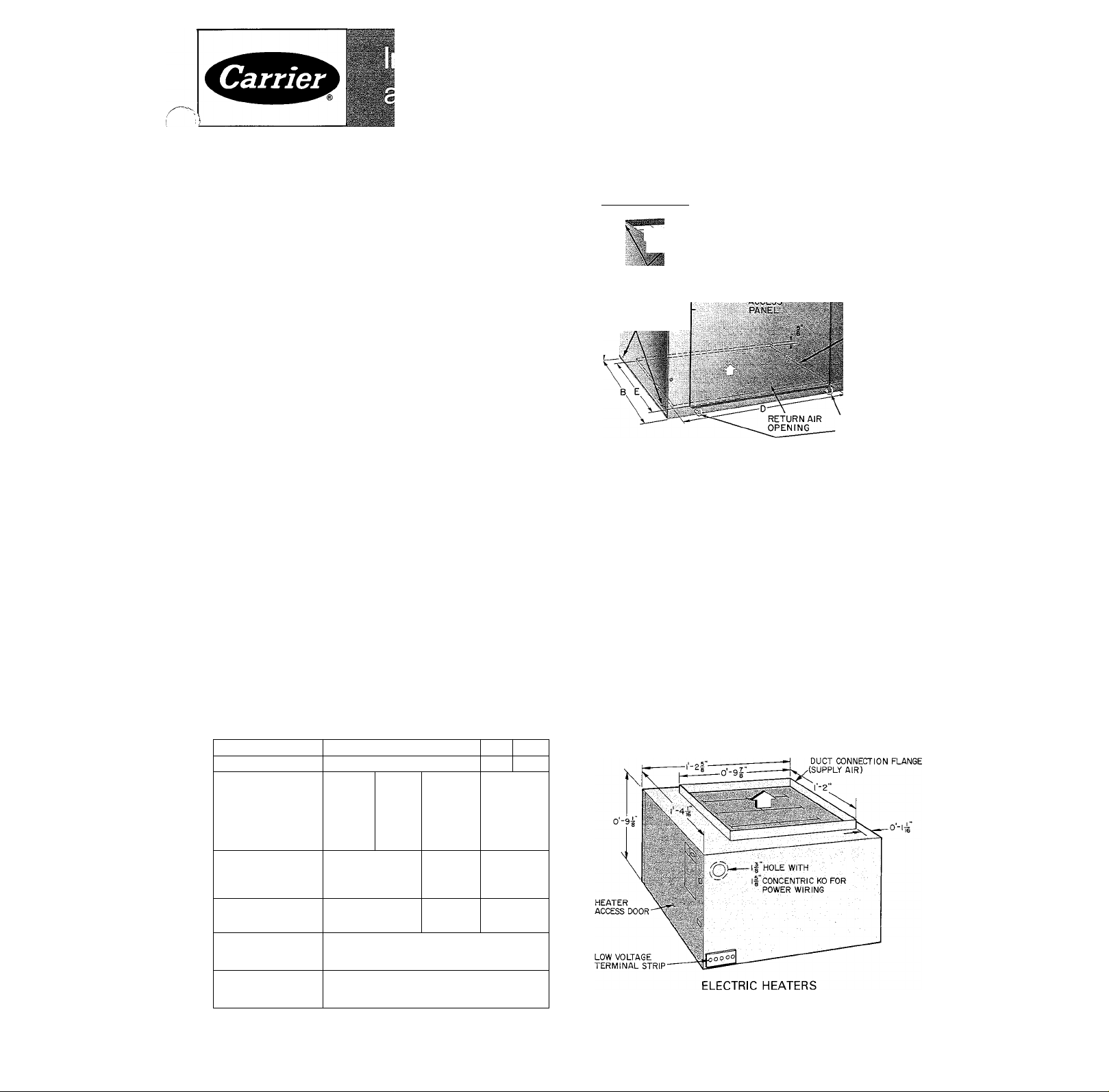
40FS FAN SECTION SUPPLY AIR
■
CLEARAtjeSHOLEP
(AONEAGMDE)
FOR ATTACHING
ELEC. HE.?çte
AND C0ÛM3 COI
OR FI LTÉ®
SECTION »
■ ^FILTER RACK MAY BE TURNED OVER TO PROVIDE EXTERNAL |-IN.
DUCT CONNECTION FLANGE.
DUCT CONNECTION „7FLANGE (SUPPLY AIR) O/'^s
f HOLE FOR
CONTROL WIRING
OPENING
k /
HEATER ACCESS DOOR
I HOLE FOR
LINE POWER
/WIRING
ALTERNATE
(INTERNAL) .
, POSITION OF I
FILTER SECTION
FLANGES*
FILTER
'SECTION
PULL RINGS FOR
-FILTER MEDIA
REMOVAL
q¿'(40FS9I6,40FQ9I6,
' ■^I638HQ9000)
. OR
2-04 (40FS920,40FQ920,
—/ 38HQ900I)
0'-9"
l| HOLE WITH CONCENTRIC
KO'S: .
I'i,
FOR POWER WIRING
ELECTRIC HEATERS
(All 38HQ, 40FS,FQ Models except 40FS916320CD
thru JR, 40FS916500EH, GM and HV)
(40FS916320CD thru JR, 40FS916500 EH, GM and HV)
Certified dimension drawings are available on request.
Fig. 1 — Dimensions and Connections
Carrier Corporation 1983
Form 40FS-11SI
Page 2
SAFETY CONSIDERATIONS
Installation and servicing of air conditioning
equipment can be hazardous due to system pres
sure and electrical components. Only trained and
qualified service personnel should install, repair or
service air conditioning equipment.
Untrained personnel can perform basic mainte
nance functions of cleaning coils and filters and
replacing filters. All other operations should be per
formed by trained service personnel. When working
on air conditioning equipment, observe precautions
in the literature, tags and labels attached to the unit
and other safety precautions that may apply.
Follow all safety codes. Wear safety glasses and
work gloves. Use quenching cloth for unbrazing
operations. Have fire extinguisher available for all
brazing operations.
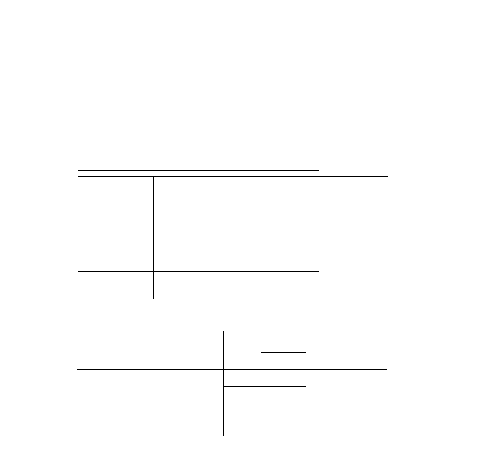
Table 2 — Height Dimensions of Assembled Units
MODULAR UNIT ASSEMBLIES
Cooling and Heating Unit
Cooling Unit 1 —
—
Coil
28H0036020
28HQ042030
28HQ048020
28H0042020
28HQ048020
28HQ060020 28VQ060020 28TQ060
28HQ036020 28VQ036020
28HQ042030
28HQ048020
28HQ042020
28HQ048020
28HQ060020 28VQ060020
-
-
-»
—
- — - -
*Total height may vary slightly depending on electric heater model used.
fLength dimension of assemblies in the horizontal position are same as
height dimension of units assembled for upflow airflow.
iAII height dimensions include 40FS filter section.
28VQ036020
28VQ042030
28VQ048030
28VQ042020
28VQ048020
-
28TQ042
-
-
-
280X036
280X042
-
— — —
28VQ042030
28VQ048030
28VQ042020
28VQ048020
-
- - - -
— — —
-
- - -
— — —
-
- -
- -
W.ARMNCi: llefore performing service or
maintenance operations on unit, turn off main
power switch to unit. Turn off accessoi\ healer
power switch if applicable, filectrical shock
could cause personal injury.
MODULAR SYSTEM INTRODUCTION
Field assemble the required 28 Series directexpansion (encased) coil and/or 40FS,40FQ,38HQ
accessory electric heater to 40FS fan section.
Combine fan section and coil for a split system fan
coil; fan section and accessory electric heater for
an electric furnace; fan section, coil and electric
heater for a heating and cooling unit. (See Table 2
for total height dimension of assembled units.)
Heating Unit
Fan Section
-
■ -
-
-
28VH002/004 40FS075/1 20
28VH002/004 40FS075/120
40FS160
40FS160
40FS200
40FS200.220
40FS160
40FS160
40FS200
40FS200.220
40FS160
40FS200.220
**For use with 38HQ227 and 234 only.
ttTotal height for 28QX coil with fan section and electric heater.
NOTE: 020.030 denotes dimensional variation within 28HQ/VQ models.
Refer to 28HQ/VQ literature for exact dimensions.
TOTAL HEIGHT'i (ft-in.)
Airflow
Upflow
Elec Heater
40FS,FO916
38HQ9000**
40FS.F0916
38HQ9000**
40FS91 6,920
40F0920
38H09001*
40FS91 6,920
40FQ920
38H0900T*
_
-
-
—
40FS,FO916
38H09000**
40FS916,920
40FO920
38HQ9001**
40FS920EH
(or Horizontal)t
3-11’^X6
4-
SM,
4- 3=46
5- OVsft
4- 7’4e
3- 3=46
3-10’/4
3-
7Va
3-1IV,6 3-11V,6
2-4=46
4- 7Ve
— 3-1IV,6 —
Downflow
4- OVe
4-
7Va
4- 3=46
5- 0%tt
4- 8’46
3- 4=46
3-10%
3- 7%
—
Table 3 — Installation and Usage Data (See Modular System Introduction, Page 3)
COIL
FAN
SECTION
40FS075 28VH002
40FS120 28VH004
40FS160
40FS200,
40FS220Í
Upflow
-
280X036,
280X042
*Electric heater for use with 208/230 V, 40FS units only. Refer to Electrical
Data and Wiring, Table 4, for fan section/electric heater usage and com
plete electric heater model numbers.
(Draw-Thru Airflow)
Upflow,
Downflow
-
Upflow
28VQ036,
28VQ042
28VO042,
28VO048,
28V0060
Horizontal
28VH002t
— —
28HO036,
28HO042
28H0042,
28H0048,
28H0060,
280X036,
280X042
Upflow,
Downflow,
Horizontal
-
28TQ042
28TO048,
28T0060
ELECTRIC HEATER*
(Blow-Thru Airflow)
Upflow,
Downflow,
Horizontal
KW
208V
40FS920300EH 7.5
40FS920300EH 7.5
40FS916300 6 - 18.8 8-25
40FS916320
40FS916500
40FO916
38HQ9000**
40FS920300
40FS916320
40FS916500
3.75-15
7.5-22.5
6-18.8
6-15
7.5-22.5
3.75-15
7.5-22.5
40FQ920 7.5-22.5 10-30
38HQ9001**
7.5-18.8
fHorizontal application not recommended for Weathermaster IV system.
iModel 40FS220 not for use with 28QX coil.
**For use with 38HQ227 and 234 only.
Heating
240 V
10.0
10.0 Fig. 2, 3
Unit
Fig. 2, 3
5-20
10-30
8-25
8-20
10-30
Fig. 2, 3
5-20
10-30
10-25
UNIT ASSEMBLY
POSITION
Cooling
Unit
Fig. 4
except dow
Heating and
Cooling Unit
iflow —
Fig. 4 Fig. 5
Fig. 4 Fig. 5
Fig. 5
Page 3

Models 28VQ,HQ coils and 40FS heaters are for
use in cooling-only and/or cooling and electric
heating systems. The 28VQ and HQ coils are also
for use in heat pump systems with 38HQ or 40FQ
electric heaters. Model 28TQ coil is for installation
in 38TQ 2-speed heat pump systems. The 28QX coil
is for solar-assisted heat pump systems. The 28VH
coil application is with Model 40FS075 only.
Fan section, coil and electric heater are tested
and approved for installation in unconditioned
space per ARI Standard (80 F db, 75 F wb indoor
temperature; 80 F db outdoor temperature). Insu
late supply and return air ductwork in uncondi
tioned space. If conditions exceed the ARI Stand
ard, additional insulation with vapor barrier may
be required for the unit.
Fan Sections 40FS can be positioned to discharge
air upward (upflow), horizontally, or downward
^(downflow), except for sizes 075, 120 which cannot
be used in downflow applications, and are suitable
for “Attic-Type” installations.
The 28 Series Coils are approved as draw-thru
(airflow) units only with the 40FS fan section. Install
coils in draw-thru position; heater in blow-thru
position. Therefore, coil must be attached to air inlet
end of fan section. As indicated in Table 3, per
missible coil airflow position(s) in system are:
28TQ — upflow, downflow or horizontal; 28VQ —
upflow or downflow; 28HQ — horizontal; 28QX —
upflow or horizontal; 28VH002 — horizontal or
^upflow with 40FS075 only, upflow with 40FS120
only.
Assembly of coils to 40FS fan section, electric
heater and filter section is described in this booklet.
For further coil information, see 28 Series installa
tion data.
COIL CONDENSATE DRAINAGE (for any unit
assembly installed above an occupied or usable
space) — In addition to normal condensate drain
line connection, install an auxiliary condensate pan
under entire unit assembly. Route drain line to any
drain that is visible to occupant. In 28 VH coil appli
cations, only the drain pan needed should be used.
See 28VH Installation Instructions.
Under prolonged high humidity conditions, elimi
nator plates may be required on downflow applica
tions. Horizontal coil installation may also require
special condensate removal methods. See Coil In
stallation Data.
Accessory Electric Heater is used with 40FS,
208/230-volt fan section. See Electrical Data and
Wiring table for fan section/electric heater usage.
Use electric heater as a blow-thru unit only by
attaching heater to air discharge end of 40FS fan
section in any of the 3 positions. Electric heater
has both heating and cooling controls including a
40-va or 60-va control circuit transformer, indoor
fan relay and low-voltage terminal strip.
MODELS 40FS916320 AND 40FS916500EH,
GM AND HV — These heaters are approved for
downflow usage but require the use of adapters
(downflow support angles) to support fan section
weight. See Installation, Heating Unit Assembly.
Filter Section is shipped taped to air inlet end of
fan section. Filter section includes a reversible
filter rack with 5/8-in. duct connection flanges. On
most unit assemblies the filter section can be
attached to unit with flanges exposed or turned over
so flanges are inside unit. The permanent one-in.
filter media pulls out (Fig. 1) for easy removal and
cleaning.
Cooling Control Kit is an accessory for 40FS,
208/230-volt fan sections used in cooling-only in
stallations. The kit contains a 40-va transformer, fan
deck filler panels, indoor fan relay and low-voltage
terminal strip. See Fig. 11, and cooling control kit
installation on page 9. Because accessory electric
heaters come equipped with cooling controls listed
above (plus required heating controls), a cooling
control kit is not required when electric heater is
used. An accessory humidity control kit is required
for use in 28TQ 2-speed installations. See Step 7
and Fig. 12.
INSTALLATION
Step 1 — Inspect Equipment — File claim with
shipping company if shipment is damaged or
incomplete.
Step 2 — Determine Position of Unit by Air
flow Direction — See Table 3 and Fig. 2, 3, 4 and
5. Ensure access panels on all units face front before
and after unit assembly.
Step 3 — Assemble Required Unit — Follow
assembly procedure below for required unit. On
downflow unit assemblies, loosen or remove fan
motor mounting bolts and rotate fan motor so
oiling holes are a minimum of 45° above horizontal
center line of motor.
Fasteners for assembling units are shipped in a
bag inside of fan section or inside electric heater
enclosure. Use the no. 10 serrated hex head sheet
metal screws (or equivalent) provided, where indi
cated in unit assembly instructions below, to ensure
proper electrical ground continuity.
( .\l NON: \ll coil'« iiiii'l be applied draw-ihru
and l1e:ller.^ blow-ihiii v\heii eombining
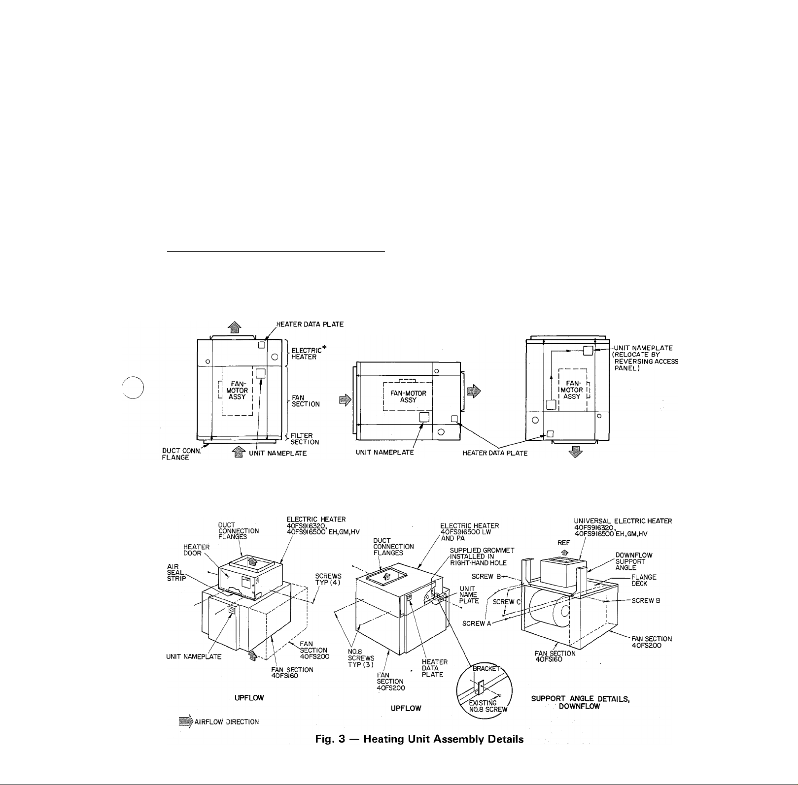
HEATING UNIT ASSEMBLY (Fig. 2)
Electric Heater Models except 40FS916320.
40FS916500EH. GM and HV. and 40FS916500LW
and PA when used with fan sections 40FS075.
-»40FS120. 40FS200 and 40FS220 — Position fan
section for upflow air direction. (Accessory flange
deck40FS900391 or40FS900401 required.) Setelectric heater on air discharge end of fan section.
Attach heater to fan section with 5 no. 8-32 self
threading screws provided. Clearance holes for
screws are provided on each side (2) and hack (1) of
fan section and engagement holes on heater.
Electric Heater Models 40FS916320. 40FS916330
and 40FS9165Q0EH. GM and HV — Position fan
section for upflow air direction. Mount heater on
fan section supply air duct connection flanges, and
attach with 4 sheet metal screws. Four clearance
holes for screws, provided on heater cabinet, can
be used as template for drilling engagement holes
in duct flanges as required. See Fig. 3. Assembly
may be aided by first removing top flange deck
from fan section (2 screws hold flange deck in place).
Assembled heater and flange deck can then be
resecured to fan section. Reposition plug buttons
Page 4
and rubber grommet positions in top flange deck to
accommodate heater fan leads. Install door air seal
strip on fan deck along front edge of heater.
Electric Heater Models 40FS916500LW. and PA
used with Fan Sections 40FS200 and 40FS220 —
Position fan section for upflow air direction.
Assemble flange deck according to instructions
shipped with accessory. Mount heater on fan section
supply air duct connection flanges; attach with 3
no. 8-32 self-threading screws and bracket provided
as shown in Fig. 3.
On all heating unit assemblies, attach filter
section to air inlet (return) end of fan section. The
filter section can be mounted with its 5/8-in. duct
connection flanges inside or outside of fan section.
Filter section is held in place with 4 screws and speed
nuts provided. See Fig. 6. Clearance holes for
screws are provided on each side of filter section.
Speed nuts provide engagement holes on each side
of fan section.
To position heating unit for horizontal airflow,
simply place assembled unit on either left or right
side with access panels at front. Position Model
40FS075 horizontally only with the motor above
the scroll as shown in Fig. 4.
For a downflow heating unit, turn assembled unit
over so fan discharges downward thru electric
heater. Remove fan section access panel. Turn
access panel so Carrier nameplate is in upright
position and replace panel on fan section.
CAU’IION: The electric heater modeK
4ii! II. (I\l. Il\ and 401
are appro\ed for downflow but w ill not support
fan section weight. When assembled unit is used
in downlliiw piisilmn. iiiNtall aCi.eNMii\ i|h\m;-
llow Niippuri ;ingle' li)l b‘J0l).14l tiisiippoii Ian
weight as describeil in Downllow Support
.Angles below.
Downflow Support Angles
1. Position fan-heater combination for upflow
arrangement (Fig. 3). Remove screws (4) secur
ing fan cover; remove and set aside cover.
2. Remove tie angle. Save screws “A” (2).
3. Install accessory fan deck filler panels as de
scribed in instructions shipped with accessory.
Assembly is similar to filler panels on accessory
cooling control kit. See Step 6 and Fig. 11.
4. Position support angles on fan section as shown
in Fig. 11. Reinstall screws “A” securing support
angles and flange deck to fan wrapper.
5. Using screws “B” supplied, attach each angle to
corresponding fan side flange. Holes in side
flanges are clearance holes.
6. Using remaining hole in each angle as a guide
drill a .128 in. diameter hole in front flange of
flange deck. Install screws “C” (supplied) in
these holes to attach angles to front flange.
NOTE: All 3 screws are required in each angle
for proper unit stability.
7. Using the 4 screws removed in step 1, reattach
fan cover so that Carrier nameplate is upside
down. Fan-heater assembly is now ready to be
inverted so that when installed in final loca
tion, nameplate will be right-side up.
The electric heater is equipped with heating
controls as described in Modular System Intro
duction. See Electrical Data and Wiring for wiring
details.
COOLING UNIT ASSEMBLY — Be sure 28 Series
coil is assembledin recommended airflow position;
DRAW-THRU AIRFLOW
Upflow
28TQ.28VQ,
28QX.28VH 28TQ,28VH
Coil casing on most models has sheet metal screw
engagement holes for assembly to fan section.
When engagement holes are not provided, carefully
drill holes where required.
Upflow and Horizontal Cooling Unit — Position
fan section for upflow air direction and coil in
upright position as shown in Fig. 4, page 6. Set fan
section on top of cooling coil casing. Attach fan
section to coil casing with 5 no. 10 hex head sheet
metal screws provided. Clearance holes for screws
are provided on each side (2) and back (1) of fan
section and engagement holes in sides and back of
coil casing. (Drill engagement holes as required).
Before attaching filter section to air inlet (return)
end of coil casing, remove return air duct flange
from coil casing. Be sure to install secondary con
densate tray with lip over edge of condensate pan
(28HQ only). The filter section can be mounted with
its 5/ 8-in. duct connection flanges inside or outside
of coil casing. Filter section is held in place with 4
screws and speed nuts provided (Fig. 6). Engage
ment holes for screws are provided by speed nuts on
each side of coil casing. Drill engagement holes in
each side of coil casing as required.
Use cooling unit as assembled above for hori
zontal airflow. To position unit for horizontal
airflow, place unit on its right side by turning it
clockwise 90°.
Downflow Cooling Unit — Install as accessory
downflow base under fan section to provide a
“firebreak” in accordance with UL requirements.
This base, which is a heater enclosure with no
heating components in it, is shown in Fig. 4. Install
base in the same manner as the heater as described
previously in Heating Unit Assembly. Also see
Fig. 2. The bases are used as follows;
FAN SECTION
40FS160300 40FS900220
40FS200300 40FS900230
40FS220300
Turn fan section (only) over so fan discharges
downward. Remove return air duct flange from
coil casing. Place coil, in an upright position, on air
inlet end (top) of fan section. Attach coil casing to
fan section with 4 no. 10 hex head sheet metal
screws provided. Clearance holes for screws are
provided in each side of fan section and engage
ment holes on sides of coil casing. (Drill engage
ment holes as required).
Downflow
28TQ.28VQ
Horizontal
28HQ,28QX,
USES BASE
40FS900230
Page 5
Set filter section on top of coil section with
filter flanges overlapping coil flanges. Drill 1/8-in.
holes thru coil and filter flanges, and fasten
together with sheet metal screws provided. Do not
drill into filter support rack. See Fig. 6.
Remove fan section access panel. Turn access
panel so Carrier nameplate is in upright position
and replace panel on fan section.
An accessory cooling control kit is required for
208-230-volt upflow, horizontal or downflow
cooling units described above. See cooling control
kit installation. An accessory humidity control
package is required for use with the 28TQ coil in
2-speed applications. See 28TQ installation data.
HEATING AND COOLING UNIT ASSEMBLY
— Attach electric heater to fan section as described
under Heating Unit Assembly. However, before
attaching filter section, proceed as follows:
Upflow and Horizontal Heating/Cooling Units —
Position heating unit assembly (Fig. 2, 3) for
upflow air direction and coil in upright position as
shown in Fig. 5 and 7. Set heating unit assembly
on top of cooling coil casing. Attach heating unit
assembly to coil casing with 5 no. 10 hex head sheet
metal screws provided. Clearance holes for screws
are provided on each side (2) and back (1) of fan
section, and engagement holes in side and back of
coil casing. (Drill engagement holes as required).
Before attaching filter section to air inlet (return)
end of coil casing: remove return air duct flange
from coil casing. Be sure to install secondary con
densate tray with lip over edge of condensate pan
(28HQ only). The filter section can be mounted
with its 5/8-in. duct connection flanges inside or
outside of coil casing. Filter section is held in place
with 4 screws and speed nuts provided (Fig. 6).
Engagement holes for screws are provided by speed
nuts on each side of coil casing. Drill engagement
holes in each side of coil casing as required.
Use cooling and heating unit as assembled above
for horizontal airflow. To position unit for hori
zontal airflow, place unit on its right side by turning
it clockwise 90°.
Downflow, Heating/Cooling Unit —^ When
40FS916320, or 40FS916500EH, GM, or HV
heaters are used in this assembly, install accessory
downflow support angles 40FS900241 to support
fan section/coil weight as described on page 3. Turn
fan section/electric heater assembly (Fig. 2, 3) over
so fan discharges downward thru electric heater.
Remove return air duct flange from coil casing.
UPFLOW
airflow direction
HORIZONTAL DOWNFLOW
*ALL HEATER MODELS EXCEPT 40FS9I6320,40FS9I6330 AND 40FS9I6500 LW AND PA. SEE FIG. 3
Fig. 2 — Heating Unit Assembly
Page 6
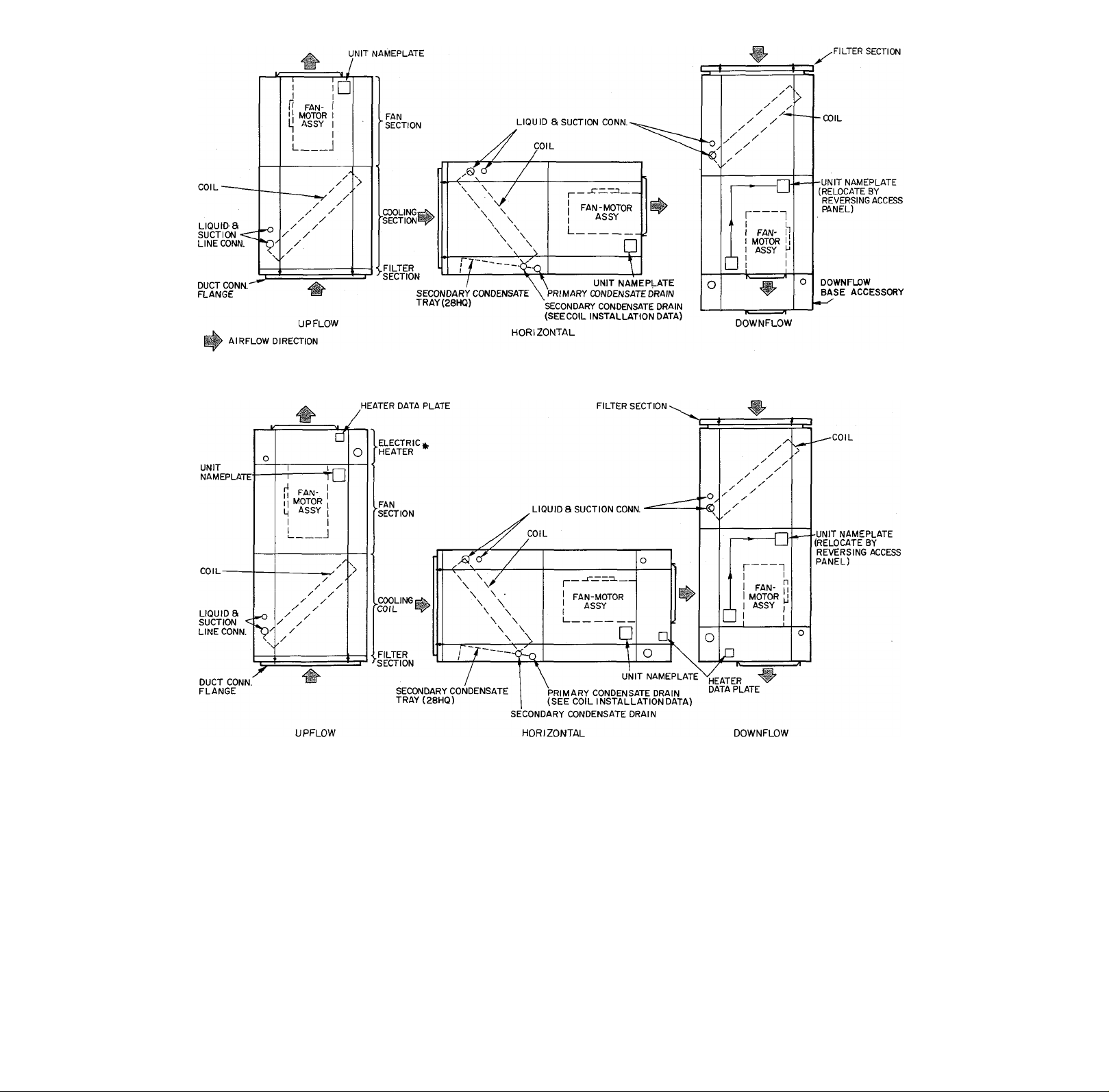
Fig. 4 — Cooling Unit Assembly
AIRFLOW DIRECTION
♦ heater 40FS9I6320 AND 40FS9I6500 EH,GM AND HV SHOWN INFIG.3
Fig. 5 — Heating and Cooling Unit Assembly
Place coil, in an upright position, on air
inlet end (top) of fan section. Attach coil casing to
fan section with no. 10 hex head sheet metal screws
provided. Clearance holes for screws are provided
on each side of fan section and engagement holes
on sides of coil casing. (Drill engagement holes
as required).
Set filter section on top of coil section with
filter flanges overlapping coil flanges. Drill 1/8-in.
holes thru coil and filter flanges and fasten
together with sheet metal screws provided. Do not
drill into filter support rack. See Fig. 6 and 8,
Remove fan section access panel. Turn access
panel so Carrier nameplate is in upright position
and replace panel on fan section.
The electric heater is equipped with heating
controls and cooling system controls as described
in Modular System Introduction. See Electrical
Data and Wiring, page 9, for wiring details.
Ductwork — Air Ducts should be installed in
accordance with the Standards of the National Fire
Protection Association, NFPA numbers 90A and
90B in compliance with paragraph 46.1-E of the
UL Standard 1096.
All 40FS units with accessory electric heaters
are suitable for installation with 0-in. clearance
from heater cabinet, discharge plenum and duct
work to combustible materials with the following
exceptions: When using 40FS920300PA (30 kw).
Page 7

all 38HQ and 40FQ models, 40FS916320 (11 to
20 kw) with 40FS200 fan section, and all 40FS916500
models, maintaina 1-in.clearance betweendischarge
plenum and ductwork to combustible materials for
a distance of 36-in. from unit. (0-in. clearance to
heater cabinet still permissible.) Use a heater spacer
plate. Carrier Model No. 40FS900310 to maintain
1-in. clearance.
SCREWS (4) SUPPLIED
SCREW CLEARANCE ]
HOLES(8)
FILTER SECTION
(SUPPORT RACK)'
FILTER SECTION
FLANGE MAY BE
POSITIONED INSIDE
(AS SHOWN) OR OUT
SIDE UNIT CASING
FDR DUCT CONN.
SPEED NUTS (4)
SUPPLIED
BOrrOM F..ANGE
ATTACHING FILTER SECTION TO FAN SECTION OR COOLING COIL IN ALL
INSTALLATIONS EXCEPT DOWNFLOW COOLING OR DOWNFLOW COOLING
AND HEATING,____________________________________
To maintain ductwork clearance on upflow in
stallations when heater top is within 3 in. of com
bustible material, set heater spacer plate over heater
discharge air opening. Attach ductwork to heater
flanges. Fig. 9. To maintain ductwork clearance
on downflow installations thru a floor: cut a 16-in. x
12-in. hole thru the floor. Set the spacer plate into
the hole. Place unit into the installed spacer plate
and connect discharge plenum to flanges provided
on heater.
Step 4 — Connect Ductwork to Unit Supply
and Return Air Openings — Duct connection
flanges are provided on fan section when used with
accessory flange deck, cooling coil, electric heater
and filter section, Fig. 1 thru 8. Two instances may
occur when duct connection flanges are not avail
able for use; when cooling unit or cooling and heat
ing unit is assembled for downflow cooling or
downflow cooling and heating with filter section
in place (Fig. 8), when filter section is installed
on fan section or cooling coil with its duct connec
tion flanges in alternate position inside of coil or
fan casing. Field-fabricated duct connections
are then required.
CAU'HON: Do not screw ductwork directly to
filter section. Screws will present removal of
Fig. 6 — Attaching Filter Section
SHEET METAL
SCREWS (2 EACH
SIDE, I ON BACK)
SUPPLIED
SHEET METAL
SCREWS (2 EACH
SIDE, I ON BACK)
SUPPLIED
'2s V
SUPPLY AIR DUCT
'CONNECTION (FLANGES)
.ELECTRIC
HEATER
FAN
SECTION
COIL
SECTION
If necessary, refer to Carrier System Design
Manual, Part 2, for system air duct design. It is
recommended that flexible connectors be used
between ductwork and unit to prevent trans
mission of vibration. (See Ductwork Acoustical
FIELD FABRICATED
SHEET METAL SCREW*
LOCATIONS (2
EACH SIDE) ON
FLANGES FOR
ATTACHING FILTER
SECTION (SEE
FIGS)
SHEET METAL
SCREWS (2 EACH
SIDE, ION BACK)
SUPPLIED
SHEET METAL
SCREWS (2 EACH
SIDE, ION BACK)
SUPPLIED
RETURN AIR DUCT CONN.TO
FILTER SECTION
FILTER
SECTION
O’ AIRFLOW
Fig. 7 —
FILTER
— ^SECTION
RETURN AIR DUCT
CONN. TO FILTER
SECTION
Upflow Heating and Cooling
Unit Assembly
CT AIRFLOW ■ ----------------------- ! SUPPLY AIR DUCT
^
*DRILL THRU FILTER SECTION FLANGES AND CCWLING COIL FLANGES TO ATTACH
FILTER SECTION. DO NOT SCREW DUCTWORK TO FILTER SECTION.
------
J'»CONN. TO HEATER
FLANGES
Fig. 8 — Downflow Heating and Cooling
Unit Assembly
Page 8

Treatment.) When electric heater is installed, use
heat resistant material for flexible connector
between ductwork and unit air discharge con
nection. Ductwork passing thru unconditioned
space must be insulated and covered with vapor
barrier. External ductwork must be insulated and
weatherproofed.
UPFLOW RETURN AIR CONNECTION THRU
THE FLOOR — Size floor opening large enough
to accept flanges on filter section. Make duct flush
with floor. Set unit on floor over opening with
filter section flanges inserted thru floor into duct.
Use fireproof resilient gasket 1/8 to 1/4-in. thick
between duct, unit and floor. For downflow supply
air connection thru the floor, proceed as above,
except size floor opening large enough to accept
flanges on unit air discharge connection. (See
combustible material specifications.)
If a side inlet return air connection is required,
use an accessory return air plenum.
ACCESSORY RETURN AIR PLENUM is avail
able in 2 sizes for use in upflow installations where
side return air inlet is required. A 21-in. wide model,
40FS900-141, is for use with 40FS160 assemblies,
and a 24-1/2 in. wide model, 40FS900-191, is for
use with 40FS200,220 assemblies and 40FS075
assemblies.
duct outlets. Metal duct systems that do not have
one 90° elbow and 10 ft of main duct to first
branch takeoff require internal acoustical insula
tion lining per the following specifications:
Line the inside of plenum, branch runs and
main duct with acoustical insulation in accordance
with the latest edition of SMACNA (Sheet Metal
and Air Conditioning Contractors National Asso
ciation) application standard for duct liner. Duct
liners should be UL classified batts and blankets
with a fire hazard classification marking of
FHC-25/50 or less. Ensure main duct lining is
extended 6 to 8 ft down the duct from plenum.
As an alternate to above, fibrous glass ductwork
may be used if constructed and installed in
accordance with the latest edition of SMACNA
construction standard on fibrous glass duct.
Both acoustical lining and fibrous ductwork shall
comply with National Fire Protection Association
as tested by UL Standard 181 for Class I air ducts.
Set 40FS heating and/or cooling assembly in
place on top of plenum. Cut opening in either side
or back of plenum and make return air ductwork
connection. Return air plenums and typical in
stallation are shown in Fig. 10.
Step 5 — Insulate Ductwork (Thermal and
Acoustical) — Insulate all ductwork passing thru
unconditioned spaces such as hot attics and crawl
spaces. Heat gain due to ductwork transmission
can result in insufficient air supply temperatures at
40FS,FQ OR
38HQ HEATER
40FS FAN SECTION
28VQ COIL
Fig. 9 — Heater Spacer Plate
AIR CLEANER
RETURN
, AIR
40FS ACCESSORY PLENUM
BASEMENT INSTALLATION
Fig. 10 — Accessory Return Air Plenum
Page 9

Step 6 — Install Accessory Cooling Control Kit
on 208/230-volt cooling only applications. As in
dicated on page 3, kit is not required on units
equipped with electric heater. Remove fan section
access panel; unpack and install control kit as
shown in Fig. 11 as follows;
1. Assemble left-hand and right-hand filler panels
using screws provided. Holes in filler panels are
provided to accommodate fan section width.
2. Cut supplied foam seal strip to fit filler panel
standing flange. Apply seal strip to back of
flange.
3. Secure cooling control box to right-hand filler
panel using screws “A” provided.
4. Remove screws “B” securing tie angle to fan
section. Remove tie angle; save screws.
5. Install filler panel/control box assembly on fan
section as shown. Secure, reusing screws “B”
plus screws provided (4 for top of panels to fan
deck; 2 for filler-to-side panels).
6. Route relay wires from control box thru wire
tie on fan assembly to fan speed selector block.
W.ARN'ING: Wires from heater must pass thru
wire tic to prevent wires from rubbing on sharp
Fig. 12 — Humidity Control Kit Installation
(28TQ Applications Only)
ELECTRICAL DATA AND WIRING
Field wiring must comply with local and national
fire, safety and electrical codes. Voltage to
unit must be within ± 10% of voltage indicated on
nameplate (voltage range at which the units will
operate satisfactorily for limited periods of time).
Contact local power company for correction of
improper line voltage.
Operation of unit on improper line \oltagc
constitutes abuse and is not covered by Carrier
Warranty.
7.
To install control box cover (not shown),
secure to hole in right-hand filler panel using
screw provided.
8.
Secure ductwork to fan section flanges (3) and
filler panel standing flange. Review ductwork
information discussed previously.
9.
Install fan section access panel.
Fig. 11 — Fan Section 40FS; Interior Details
Step 7 — Install Accessory Humidity Control
Kit (for 230-v, 28TQ application). See Fig. 12.
Attach supplied bracket to rear of control box using
hole closest to strain relief. Place control box in
upper right-hand corner of 40FS fan section. Secure
control box by fastening bracket supplied to support
bracket of fan section.
See Tables 4 and 5 for recommended wire and
fuse sizes.
Step 8 — Install a Branch Circuit Disconnect
Switch(es) per NEC. One disconnect switch is
required on all unit assemblies except those
which include 40FS916320 (11- to 20-kw) electric
heaters. Standard assemblies using these heaters
require 2 disconnect switches for 2 line power
circuits. If one line power circuit, using one dis
connect, is required, attach an accessory line power
connection conversion lug set (Lug Adapter Kit —
Part No. 40FS900271) to fuse terminals in electric
heater. Installation may be aided by first attaching
adapter lugs to wire then positioning lugs to fuse
block. See Fig. 13C.
Locate disconnect(s) within sight from and readily
accessible from the unit, per section 440-14 of
National Electrical Code (NEC).
Step 9 — Route Line Power Leads Into Unit —
Extend leads from disconnect per NEC thru hole
provided (Fig. 1) into cooling control kit or acces
sory electric heater. (Cooling control kit not
required when heater is used.)
Step 10 — Connect Ground Lead(s) to the
Ground Screw in Cooling Control Kit or
Grounding Lug in Electric Heater Control
Section for safety. Connect power wiring. Fig. 13.
Splice power leads to pigtails in cooling control kit
or connect leads to fuse terminals or terminal board
on electric heater.
When using control kit, splice a power lead to
black transformer pigtail on 230-volt units or red
transformer pigtail on 208-volt units. Cap unused
transformer pigtail.
When using an electric heater on 230-volts,
connect the red transformer pigtail to heater hne
voltage terminal. When using heater on 208-volts,
Page 10

connect blue transformer pigtail to heater line
voltage terminal. See heater label wiring diagram.
Cap unused transformer pigtail.
For splice connections or capping pigtails, use
wire nuts provided: Tape each connection.
Three-speed fan motor on all units (except Model
40FS075) may be connected for high, medium or
low fan speeds as described below. Refer to Table 7
for minimum allowable fan speeds when electric
heaters are used.
Step 11 — Set Fan Motor Speed(s) — High,
medium or low fan speed leads are provided on
motor for choice of fan speeds. Motor leads are
factory connected to fan speed selector block
located on fan housing (Fig. 11 and 13). Selector
block terminal 1 is high fan speed, terminal 2 is
medium fan speed and terminal 3 is low fan speed.
Model 40FS075 utilizes terminals 1 and 2 only.
Line power leads are supplied with cooling
control kit and electric heater for connection to
fan speed selector block as directed in Fig. 13.
Route yellow and black power leads which
extend thru hole in back of cooling control kit to
selector block. Route yellow and black or yellow,
black and red power leads from electric heater thru
power openings (Fig. 15) in bottom of heater
casing and fan section deck to selector block.
One fan speed may be selected for coohng only
unit assembly, heating only or cooling and heating
unit assembly when 40FS916320 or 40FS916500
heater is used.
Two fan speeds may be selected for remaining
combined cooling and heating assemblies; a heating
speed and a cooling speed. (See Table 7 for
Minimum Fan Speeds on heating application.) For
single fan speed operation on these heating only or
heating and cooling assemblies, remove red lead
from heater fan relay terminal 5 or 6. Connect a
black jumper (supplied) between fan relay terminal
6 and fan relay terminal 4 (40FS,FQ916, or
38HQ9000 heaters) or terminal 5 (40FS,FQ920, or
38HQ9001 heaters). Connect black heater lead to
fan speed selector block for speed required. See unit
label diagram for details.
40FQ9I6, OR 38HQ9000
40FS9I6300
,,
___
TO FAN CZ]—RED
SELECTOR ADD
BLK ([!□—BLK-
, REMOVE
factory)
WIRING )
I FACTORY
I WIRING
BLK-
40FQ920, OR 38HQ900I
40FS920300
1
Step 12 — Connect Control Power Wiring
(24-volt) with Cooling Control Kit or Electric
Heater — Use 40- or 60-va transformer supplied
as part of cooling control kit or electric heater
controls as 24-volt supply for system. A onetransformer control wiring hookup is recommended
for ease of installation. When outdoor unit trans
former is used together with control kit (or heater)
transformer, a phasing problem may result. If both
transformers are used, also use a thermostat with
isolating contacts to prevent interconnection of
class 2 (24-v) outputs.
10
Page 11

A. COOLING ONLY UNITS
I-PHASE CONN.
TO DISCONNECT PER NEC
230V OR 208V TAP
I I
BLK RED
J
____
L
( PRIMARY 1
ITRANSFORMERI
UecqndaryJ
f~
YEL
1 /
COM
PL-I PL-2 PL-3
FAN SPEED SELECTOR BLOCK
(I-FAN SPEED OPERATION)
l-PHASECONN. TO DISCONNECT PER NEC
LINE VOLTAGE |
TERMINAL BOARD |
0N5-KWT0I0-KW I
HEATER
CONTACTS
TAPE UNUSED LEADS
FAN
RELAY
(k
GROUND
—I CONN.
B. HEATING ONLY OR HEATING AND COOLING UNITS
(WITH ALL HEATER MODELS EXCEPT 40FS9I6320, 40FS9I6500
I
COOLING
CONTROL
KlTdFAN SPEED
OPERATION)
AND CIRCUIT BREAKER VERSIONS OF ALL 40FQ)
TERMINAL
BOARD 2
TO lO-KW HEATER
GROUND LUG (LOCATED
NEAR TRANSFORMER)
I-PHASE CONN.
TO DISCONNECT PER NEC
ON 8-KW
------
TAPE
UNUSED
LEADS
Q /
230V OR 208V TAP
[transformer
\SEC0NDARY/^
RED
( PRIMARY ^
I
11 I
'
C. HEATING ONLY OR HEATING AND COOLING UNITS
(WITH MODEL 40FS9I6320 HEATER)
1-PHASE CONN. TO DISCONNECT PER NEC
!
1
GROUND
LEAD
1
l-PHASE CONN
1
TO DISCONNECT
1
1
1
1
1
I-PHASE CONN.
TO DISCONNECT PER NEC
L2 LI
U-CKTA—H
*
F5
L_T5n ground lug ( LOCATED NEAR
YELIBLK
FI
F3
1 [-KW TO 30-KW HEATER
-TRANSFORMER)
38HQ HEATERS ONLY
ELECTRIC HEATER
CONTROL BOARD
F2 F4
FUSE BOARD ON
I
COM PL-I
FAN
-PHASE CONN. TO DISCONNECT PER NEC
' 1
GROUND
LEAD
1
PL-2 PL-3
SPEED SELECTOR BLOCK
FAN
motor;
1 1
1 I
l^CKTA^
1 1
F6
BLU
GROUND LUG (LOCATED
NEAR TERMINAL BOARD)
r^-
D. HEATING ONLY OR HEATING AND COOLING UNITS
(WITH MODEL 40FS9I6500 HEATERS)
3-PHASE
FIELD
POWER
CONN.
<^!> <^>
TERMINAL BOARD
18-KW UNITS
10-KW TO
SELECTOR BLOCK TERMINATIONS
COM-COMMON
PL-1 - HIGH
PL-2 - MED
PL-3 - LOWt
Q
230V OR 208V TAP
( PRIMARY ^
iTRANSFOR~MEg
Lseconda’ryJ^
GROUND
m
FUSE BOARD
mn
1 FU2
1 FU3
1 FU4
1 FU5
1 FU6
25-KW AND 30-KW UNITS
------
------
-- 0 I .GROUND LUGS (LOCATED I 0 I
---------^ NEAR FUSE BOARD) ^
TAPE UNUSED
LEAD^
--------------
-----------------
ELECTRIC HEATER
CONTROL BOARD
( l-FAN SPEED OPERATION)
YEL (COOLING a HEATING)
/ s
COM
PL-I PL-2 PL-3
FAN SPEED SELECTOR BLOCK
HEATING ONLY OR HEATING AND COOLING UNITS
/r\
h)-
3-PHASE
FIELD
■■
POWER
CONN.
Line Voltage Connection
Splice Connection
Field Wiring
Factory Wiring
Accessory connection conversion
lug set. See text for power wiring.
o o © <s>
0 0 0 0
STANDARD FUSE BOARD ON ll-KW
TO 20-KW HEATER W/ACCESS.
CONN. CONVERSION LUG SET
—f 0~I GROUND LUG
FAN ’
motor;
(UNITS 40FQ WITH CIRCUIT BREAKERS)
CIRCUIT BREAKER
BOARD (TYP)
I - PHASE FIELD
POWER CONN,
• — GROUND
*Fuses 5 and 6 only on heater models over 20 kw.
tPL-3 not used on Model 40FS075.
NOTES:
1. Branch circuit wiring data as shown in Table 4.
2. Tape or cap all unused wire leads.
3. For 1 fan speed operation, see text for power
wiring.
Fig. 13 — Line Power Connections
11
Page 12

FAN
SECTION
40FS075
^ 40FS120
40FS160
40FS200
or
40FS220
Table 4 — Heater Electrical Data and Usage
Heater
Model
240 V
40FS920300
(1-Ph)
40FS916300 FE 12.0
(1-Ph) FQ 13.0
40FQ916 030
(1-Ph)
38HQ9000
(1-Ph)
40FS920300
(1-Ph)
40FQ920
(1-Ph)
38HQ9001
(1-Ph)
EH 10.0 7.5 1
DL
DX 9.0
EH 10.0 7.5
ET 11.0
GB 14.0
GM 15.0
JR 20 0
LW
Old
060*
020
070*
080*
040
090*
050
100*
61
71 10.0 7.5
81
91
EH 10.0 7.5
ET 11.0 8.3
FE
FQ 13.0
GB 14.0 10.5 1 A 55.5 48.0 2
GM
JR
LW
PA
060
120*
070
130*
080
140*
090
150*
100
160*
01 10.0
11 15.0 11.3
21 20.0 15.0
31
8.0 6.0
25 0
8.0 6.0
10.0 7.5
15.0
20.0
25.0 18.8
8.0
15.0 11.3
20.0 15.0
12.0 9.0
15.0 11.3
20.0
25.0 18.8
30 0
10.0 7.5
15.0 11.3 1 59.5 51.6
20.0
25.0 18.8
30.0
25.0 18.8
ELECTRIC RESISTANCE HEATER (208/240 V)
Kw
No.
208 V 240 V 208 V
A
Htr
Amps
240 V 208 V 240 V
39.6 34.4 4
1 A 33.3 28.9
1
37.5
6.8
A
32.5 6
1 A 41.6 36.1 4
8.3
9.0
9.8
10.5
11.3
150
188
11.3
15.0
6.0
1 A 45.8
1
A 50.0
1 A
1 A
1 A
1 A
104.2
A
1
1
1
A
1
/\
1
/y
1
104.2
1 33.3
A
1
41.6 36.1
/\
1
62.5 54.2
39.7 4
43.4
54.2
47.0
58.3 50.5 2
62.5 54.2 2
72.2
83.3
90.3
33.3
41.6 36.1
54.2
62.5
83.3 72.2
90.3
28.9
1 83.3 72.2
1 A 39.6 34.4 4 6
1
43.6
A
37.8
1 A 47.6 39.4 4 4 65
1
51.6
9.8
A
44.8
1 A 59.5 51.6 2 2
1 A 79.3 68.8
15.0
1 A 99.2
22 b 1 A 119.0 103.2
86.0
1 39.6 34.4
1 79.3
15.0
22.5
7.5
1 Ai
/y
1
119.0 103.2
1 A<
39.6 34.4
A 59.5
1
1 A 79.3
1 99.2
99.2
68.8
86.0
51.6
68.8
Rfi n
Min Wire
Size (AWG)
6
4 4
2 4
2t
ot
6t
6t
4t
6t 6t
2t
4t 4t
It 2t
2t 2t
OOf
Ot
6t
6t
4t
6t
2t
4t
It 2t
2t 2t
4
2 4
It
Ot
oot
4t
6t
2t 2t
4t
n It
2t 2t
oot
Ot
oot
ooot
oot Ot
4t
6t
6t
6t
2t 2t
4t 4t
It It
2t
2t
oot
Ot
Ot
It
Branch Circuit
Max Ft
Wire
208 V
6
80
8 60
6 55 55
6 80
75 45
6
70
100 65
4
75 60
2 85
2
65 65
80 65
It
60 60
6t
60 40
8t
80 50
6t
50 50
85 70
2t
55 55
85 65
65 65
100
Ot
8t
6t
6t
2t
4t
80 65
It
60 60
6t
60 40
80 50
50 50
85 70
55 55
85 65
65 65
80 50
6 75 45
100 60
4
90 55
85 85
2
85 70
85 70
n
90 70
ot
80 50
6t
50 50
6t
90 90
55 55
4t
85
70 70
105 85
Ot
85
It
110 90
90 70
80 50
50 50
90 90
55 55
85 85
70
70
105 85
85 1
70
Min Gnd
Wire Size
208 V
240 V
50
40
10 10 60** 60**
10 10
10 10 60** 45**
10 10
50
10 70 60
8
65
8 10 70
8 8
8 8
70
8 8
6 8 110 100
6
10 10 50** 40**
1_Q
10 60** 50**
8 8 90 80
0
85
0 0
10 10 50** 40**
10 60**
10
8 8 90 80
0
10 60** 60**
10
8 10 70 60
70
8 10 70 70
8
8
8 8 80 70
8
8
6
8 110 100
6 6
6 6
10 10 60**
8 8 90 80
85
70
0
0 0
6
8 110 100
0
10 10 60** 60**
8 8 90 80
0
8 110 100
6
6 150 125
Fuse/CB
Amps
208 V
240 V
50** 40**
. 60** 50**
80
80 70
90
6
150 125
8 110 100
150 125
8 110 100
80 70
90 80
150 125
175 150
60**
150 125
150
175
60
70
80
50?**
12
Page 13

FAN
SECTION
40FS160,
40FS200
or
40FS220
Model
40FS916320
40FS916500
(3-Ph)
Table 4 — Heater Electrical Data and Usage (cent)
ELECTRIC RESISTANCE HEATER (208/240 V)
Kw
240 V 208 V
CD
CP 6.0 4.5 1 A
DA
DF
DL
DX
EH
—
i ETtt
■,__ _
1 FEtt
FQtt
GBtt
; GMtt
GY .
; HJtt 17.0 12.75
HVtt
JFtt 19.0 14.25
JRt+ 20.0
EH
GM 15.0 11.3 1
HV 18.0 13.5 1
LW ■
PA : 30.0 ;
5.0 3.75 1 A
7.0
5.25
7.5 5.63 1 A
8.0 6.0 1 A
9.0 6.75
10.0 7.5 1 A
11.0 8 25
iiiSiiPM
12.0 9.0
13.0 9.75
140 10.5
15.0 11.25
16.0 12 0
18.0 13.5 A
15 0
10.0 7.5 1
18.8
22 5 1
No.
nUfc
Htr
Amps
240 V
208 V 240 V 208 V
Min Wire
Size (AWG)
20.8 18.0 8 10
25.0 21.6 8 8 50 60
1 A 29.2
31.3 27.0
33.3 28.9
1
A
37.5 32.5
41.6
1 A
45.8
A
25.0 21.6
8
20.8 18.0
1
A
50.0
A
29.2 25.2
2
B
20.8 18.0
1 A
54.2
A
33.3 28.9
2
B
20.8 18.0
1
A 58.3
A
37.5 32.5
B
20.8 18.0 10
1
A 62.5 54.2 2
A
41.6
2
B
20.8
1 A
66.7 57.7 2
A 33.3
2
B 33.3
1 A
70.8 61.3
A
35.4
0
B 35.4
1 A
75.0 64.9 1 2 90 85 8 8 100 90
25.2 6 8 70
6
6 6 65 70
6 6 55 65 10
36.1
39.7
4 6
4 6 75 55 8
8 8 50 60
10
43.4 4
6 8 70 50 10 10 45
10
47.0
2
6
10
50.5
2
6 6 55 65 10 10 60 50
36.1
18.0
4 6 80 60 10 10 60 60
10 10 45
28.9 6
28.9
6 8 70 55 10 10
2 2
30.6
6 6
30.6 6 8 65 50 10 10 45 40
37.5 32.5 6 6 55 65 10 10 60 50
B
37.5 32.5 6 6
1 A
79.2 68.5
A
39.6
34.3
B
39.6 34.3 6 6 60 70 10 10 50 45
1 A
83.3 72.2
A
41.6 36.1
2
B
41.6 36.1 6 6 55 65 10 10
24.0 20.8
36.0 31.3
43.3
37.5
2t
6 6
2t
4
8t 8t
6t 8t
6t
1 60.2 52.2 4 4
72.2 62.5 2
Branch Circuit
8 65 50
10 45 55 10 10 30
4
10 45 55 10 10 30
4
6 60 70 10 10 50 45
10 45 55 10 10 30 25
4 100
10 45 55 10 10 30 25
2
2
6 60 70 10 10 50 45
2
1
6 80 60 10 10 60 60
6t
4
Max Ft
Wire
240 V 208 V
60 45
Min Gnd
Wire Size
240 V 208 V 240 V 208 V
Fuse/CB
Amps
10 10 35 30
10 10 40
50
10 10 45 40
10 10 45
10
10 50 45
10 60
60
80
10
10
60
10 70 60
10
10 40
80 8
70
10 70 60
100 70 8 8 80 70
70
8
8
80 70
90 100 8 8 90
55 10
10
30 25
80 90 8 8 90 80
45
90 8 8 100 90
80
65 10 10 50 45
60
70 10 10 50 45
60
80 6 8 110
70
55 60 10 10 60 50
95 6 8
65
110 100 •
60 50
70 60 10 10 40 35
65 40 10 10 60 45
55
55 10
10
60 60
65 65 8 8 90 80
90 55 8
8
100
35
40
50
60
35
25
40
25
80
40
100
90
Two-stage electric heaters. Remaining heaters are singlestage. See Fig. 15.
CB — Circuit Breaker
^Circuit breaker models. All remaining models over 10 kw are in
ternally fused.
tCopper wire sizes based on 75 C; all other copper wire sizes
based on 60C. Use copper wire only.
JCopper wire rated at 75 C and no larger than 00 size must
be used.
**Use fuses only on 40FS91 6300 DL, DX, EH, 40FQ91 6010,020,
40FQ920060 and 40FS920300 EH units.
tfStandard heater models that require 2 line power circuits. Add
accessory conversion lug set for single power circuit operation.
NOTES:
1. Heater models 40FQ916, 40FQ920 and 40FS916320 equipped
with 60-va control circuit transformer. Remaining heater
models have 40-va transformer.
2. Field-selected wire sizes must not create a voltage drop
between power source and unit in excess of 2% of unit
rated voltage.
13
Page 14

THERMOSTAT HHOIAD040 0R042W1TH
HH93AZ040 OR 042 SUBBASE
FAN SECTION
COOLING CONTROL KIT
I l-KW TO 20-KW,
ARRANGEMENT ACOOLING ONLY. (SEE NOTE I BELOW)
THERMOSTAT HH0IAD040 OR 042 WITH jq is-kw
HH93A2040 OR 042 SUS8ASE ELECTRIC HEATER
AND I-STAGEHEATING WITH,8-KW TO 15-KW,
40FS9I6300 OR 40FS920300 HEATER.
(SEE NOTE I BELOW)
THERMOSTAT HH07AT070
SUBBASE HH93AZ080
ARRANGEMENT C- COOLING
AND 2-STAGE HEATING WITH.20-KW TO 30-KW,
40FS9I6300 0R40FS920300 HEATER.
(SEE NOTE I BELOW)
THERMOSTAT HH0IAD04O OR 042 5-KW TO 10-KW,
WITH HH93AZ040 OR 042 SUBBASE ELECTRIC HEATER
20-KW TO 30-KW
ELECTRIC HEATER
LOW-VOLTAGE
TERMINAL BOARD
CONO UNIT
CONO UNIT
40FS9I6320 HEATERS. (SEE NOTE 1 BELOW)
THERMOSTAT HH07AT07I WITH
HH93AZ073 (AUTO. CHANGEOVER)
OR HH93AZ075(MANUAL 40FQ
CHANGEOVER)SUBBASE. ELECTRIC HEATER
(SEE NOTE 2 BELOW.) TERMINAL BOARD
ARRANGEMENT F-COOLING
AND 2-STAGE HEATING-38CQ HEAT PUMP AND
40FQ HEATER (ALL); SUPPLEMENTAL HEAT, NO OUTDOOR
THERMOSTATS.(SEE NOTE I BELOW) REFER TO 38CQ
OR 38RQ HEAT PUMP INSTALLATION INSTRUCTIONS
IF OUTDOOR THERMOSTATS ARE USED.
THERMOSTAT
SUBBASE
HH93ÀZ073
OR HH93AZ075
40AQ.38HQ OR 40FQ
ELECTRIC HEATER
TERMINAL BOARD
38HQ
COMPRESSOR SECTION
TERMINAL BOARD
38CQ0R38RQ
HEAT PUMP
TERMINAL BOARD
40FS9I6320 HEATERS. (SEE NOTE I BELOW)
Eliminate shaded wiring connections for heating only
applications.
CR — Control Relay
ODT — Outdoor Thermostat
SHR — Supplemental Heat Relay
-----------
Factory Wiring
-----------
Field Wiring
*A 40-va transformer is located in cooling control kit and
*
40FS916300,920300 electric heaters. All 40FS916320,330,500
and 40FQ916,920 electric heaters have a 60-va transformer that
is internally fused. All 38HQ heaters have a 75-va transformer
that is internally fused. Do not short secondary terminals.
Fig. 14 — Control Wiring Connections
(38HQ WITH 40AQ OR 40FS/28HQ.VQ
EQUIPPED WITH ELECTRIC HEATER,
SUPPLEMENTAL HEAT,
NO OUTDOOR THERMOSTATS)
REFER TO 38HQ HEAT PUMP INSTALLATION
INSTRUCTIONS IF OUTDOOR THERMOSTATS
ARE USED.
fRemove jumpers from 40FQ heater terminfl board to wire with
outdoor thermostat(s).
^Remove factory-installed jumpers (connection B) when installing
outdoor thermostats (ODT).
NOTES:
1. For simplicity, arrangement identifications below diagrams do
not call out fan section/coil model numbers. See Modular Sys
tem Introduction and Tables 2, 3 and 4 for fan section/coii/
heater models and usage.
2. Thermostat/subbase package numbers: 38CQ900081 for
HH07AT071/HH93AZ073 (auto, changeover); 38CQ900111
for HH07AT071/HH93AZ075 (manual changeover).
3. See Carrier price pages for other approved thermostats.
14
Page 15

Table 5 — Fan Section Electrical Data
FAN SECTION
Branch Circuit
Model
40 FS
Volts
(1-ph)
FLA
Wire
Size*
(AWG)
075
120
160 208/230
200
220
0.9 14
1.5
14
3.5 14
4.5 14
6.9
14
FLA — Full Load Amps
*Copper wire sizes based on 60 C. Use copper wire only.
NOTÉS: 1. See Table 4 for units equipped with electric heaters.
2. When 40FS unit is equipped with electric heater, fan motor line power is
supplied from electric heater line power circuit.
Table 6 — Thermostat Anticipator Settings
Max
Ft
Wire
Fuse
Amps
399 15
240
103 15
80 15
52 15
15
40FS916300
40FQ916
38HQ9000
40FS920300
40FQ920
38HQ9001
HEATER
MODEL
1 St Stage
DL
OX
EH
ET
FE
FQ
GB
GM
JR
LW
010
060
020
070
030
080
040*
090*
050*
100*
61
71
240 V
8.0 6.0
9.0 6.8
10.0 7.5
11.0
12.0 9.0
13.0
14.0 10.5
15.0 11.3
10.0 7.5
15.0
8.0
10.0 7.5
10.0 7.5
10.0 7.5
15.0 11.3
8.0 6.0
10.0 7.5
208 V 240 V 208 V
81 10.0
91
EH
ET
FE
FQ
GB
GM
10.0 7.5
10.0 7.5
11.0 8.3
12.0
13.0 9.8
14.0 10.5
15.0 11.3
JR 10.0 7.5
LW
PA
060
120
070
130
080
140
090*
150*
100*
160*
01
11
21
31
15.0 11.3
20.0 15.0
10.0 7.5
. 10.0 7.5
10.0
15.0
11.3
20.0 15.0
10.0
10.0 7.5
10.0
15.0 11.3
8.3
9.8
11.3
6.0
7.5
9.0
7.5
7.5
7.5
KW
ANTICIPATOR SETTING
2nd Stage 1 St Stage 2nd Stage
__
_
__
— —
— —
— —
—
— —
10.0
10.0
— —
—
5.0
240 V
—
—
—
.16
.16
.16
.16
.16
208 V
.14
.14
.14
.14
.14
.16 .14
—
.16 .14
.16 .14
7.5
7.5
.16
.16
.14
.14
.16 .16
- .16 .16
3.75 .16 .16
240 V
— ,
__
—
—
—
— —
— —
.16
.16
— —
— ' — ■
.16
10.0 7.5 .16* .16* .16* .16*
10.0 7.5 .16* .16*
— —
5.0
—
3.75 .16 .16
.16 .16
.16 .16
.16*
■
-------
— —
.16 .16
10.0 7.5 .16* .16* .16* .16*
— —
—
—
—
— —
— —
10.0
10.0
_
7.5
7.5
10.0 7.5
— —
5.0
3.75
10.0 7.5
10.0
10.0
— —
5.0
7.5
7.5
3.75
10.0 7.5 .16
.16 .14
.16 .14
.16 .14
.16
.16
.14
.14
.16 .14
.16
.14
.16 .14 .16 .14
.32 .28 .16
.16
.16
.16 .16 .16 .16
.16 .16 .16 .16
.16* .16* .16* .16*
.32* .32* .16* .16*
.16
.16
.16 .16 .16 .16
.16 .16 .16
' 10.0 7.5 .16 .16
— —
— —
— —
— —
— —
— —
.16
— —
— —
.16* .16*
208 V
—
—
—
—
—
.14
.14
.16
.16*
—
.14
.14
15
386
Page 16

Table 6 — Thermostat Anticipator Settings (cont)
HEATER
MODEL
40FS916320
40FS916500
1 St Stage
240 V 208 V
CD
CP 6.0 4.5
DA
DF
DL
DX
EH
ET*
FE*
FQ*
GB*
GM*
GY*
HJ*
HV*
JF*
JR*
EH 10.0 7.5
GM
HV
LW
PA
5.0
7.0 5.25
7.5 5.63
8.0 6.0
9.0 6.75
10.0 7.5
6.0 4.5
7.0 5.25
8.0
9.0 6.75 5.0 3.75
10.0 7.5
8.0 6.0 8.0 6.0
8.5 6.38 8.5
9.0
9.5 7.13
10.0 7.5
15.0 11.3
18.0 13.5
12.5 9.4
15.0 11.25 15.0 11.25 .23 .23 .23 .23
KW
2nd Stage 1 St Stage
240 V
3.75
6.0 5.0 3.75
6.75
— —
— — .25
— —
— — .25
— —
— —
—
5.0 3.75
5.0
5.0 3.75
9.0 3.75
9.5 7.13 .25* .25* .25* .25*
10.0
— — .23
— — .23 .23 — —
— —
12.5
208 V
—
3.75
6.38 .25* .25*
7.5
9.4
240 V 208 V
.25
.25
.25
.25
.25
.25*
.25*
.25* .25*
.25* .25*
.25* .25*
.25* .25*
.25*
.25* .25*
.23
.23 .23 .23 .23
*Heaters that may be wired for 1- or 2-stage operation. When wired for 1-stage operation, add first and second stage anticipator settings.
ANTICIPATOR SETTING
2nd Stage
240 V
.25
.25
.25 — —
.25
.25 — —
.25 — —
.25
.25*
.25* .25*
.25* .25* .25*
.23
.23
— —
— —
— —
— —
.25* .25*
.25* .25*
.25* .25*
.25* .25*
.25* .25*
.25*
.25* .25*
— ■ —
— —
208 V
.25*
.25*
Table 7 — Minimum Fan Speeds^
FAN
SECTION
40FS075
40FS120
40FS160
40FS920300 10.0
40FS916300
40FS916320
40FS916500
40FQ916
38HQ90000
Model
or
HEATER
240 V
and
and
and
20
25
10
11
20
10
18
25
30
10
15
to
25
to
15
to
to
to
Kw
208 V
7.5
6.0
8
to
11.3
15
and
18.8
5
3.75
to
7.5
8.75
to
15.0
7.5
to
13.5
18.8
and
22.5
8
6
and
7.5
11.3
to
18.8
‘Minimum fan speed and cfm for safe eiectric heater operation.
MIN
FAN
SPEED
Low
Low
Medium
Low
Medium
Medium
High
Low
Low
MIN
CFM
650
1200
1350
950
950
1000
1400
1130
1130
FAN
SECTION
40FS920300
40FS916320
40FS200
or
40FS220
40FS916500
40FQ920
or 38HQ90001
(W/40FS200)
40FQ920
(W/40FS220)
tMinimum cfm is 1960 (High Speed) when 40FS200/40FQ920 is
used with 38RQ054.
Model
HEATER
240 V 208 V
and
and
20
25
30
11
20
10
18
25
30
10
30
10
30
10
to
to
10
to
to
to
to
Kw
7.5
to
15
18.8
and
22.5
5
3.75
to
7.5
8.25
to
15.0
7.5
to
13.5
18.8
and
22.5
7.5
to
22.5
7.5
to
22.5
MIN
FAN
SPEED
Low
Medium
Low
Medium
Medium
High
Medium
Low
MIN
CFM
1600
1800
1200
1200
1000
1400
1550t
1550
START-UP
Adjust room thermostat as follows:
1. When electric heater is used, set thermostat
anticipator settings according to Table 6. These
settings may be changed slightly to provide a
greater degree of comfort for a particular
installation.
2. Set thermostat selector switch at OFF.
3. Set thermostat fan switch at AUTO, or FAN.
4. Turn on main disconnect switch(es) to unit.
5. Set thermostat dial to the desired temperature
(above or below room temperature).
6. Set selector switch at HEAT or COOL.
7. If necessary, adjust the system airflow (cfm) by
changing fan motor speed. See Electrical Data
and Wiring for fan speed adjustment. Refer to
Table 7 for minimum allowable fan speed when
electric heaters are used.
16
Page 17

FAN SECTION SERVICE
I )¡momiu.v1 pi)w«. i In iill 1'iii.ims K’lmvM’l\ к■inü
Remove unit front access panels for cleaning,
lubrication or parts replacement (Fig. 15).
LOW-VOLTAGE
TERMINAL
STRIP
ELECTRIC
HEATER
FILTER
SECTION
C|>AIRFLJDW T-J
Fig. 15 — Upflow Heating and Cooling Unit
Interior Details (Typical)
USIBLE LINK
LIMIT SWITCH
SEQUENCERS
-TRANSFORMER
■ POWER LEAD ROUTE TO
FAN SPEED SELECTOR
BLOCK
COOLING CONTROL KIT
(NOT REQ'D WHEN ELEC
■ HEATER IS USED; HUMIDITY
CONTROL KIT REQ'D ON
28TQ INSTALLATIONS)
FAN SPEED SELECTOR
BLOCK
FAN WHEEL (BLOWER
ASSEMBLY)
■ CONDENSATE DRAINSHORIZONTAL
INSTALLATIONS
CONDENSATE DRAINSUPFLOW OR DOWNFLOW
INSTALLATIONS
RINGS FOR FILTER
REMOVAL
1. Shut off unit power.
2. Remove fan section access panel.
3. Disconnect motor wires at fan speed selector
block.
4. Where applicable, disconnect wires from cool
ing control box and remove control box.
5. Remove tie angle screws and tie angle (these
screws secure front corners of filler panels to
fan section side panels as shown in Fig. 11).
Remove screws to allow filler panels to be
raised slightly.
6. Grasp blower assembly firmly — left hand on
motor, right'hand on scroll right side inlet.
7. Pull blower assembly forward. Rotate assembly
so that rear drops slightly, allowing assembly to
pass thru front of unit.
8. Reassembly is the reverse of the above pro
cedure. Note that when reassembling, rear
flange of blower outlet sits on top of fan deck,
tab on forward edge of outlet erigages slot in
front of fan deck.
Cleaning — Remove caked-on dirt from fan wheel
and housing with brush; remove grease with mild
solvent. When replacing blower assembly, ensure
fan wheel is centered in housing.
Return Air Filter — Pull rings (Fig. 1) are provided
for removing 1-in. permanent filters. Inspect filter
frequently. Clean filter with a vacuum cleaner or
wash with mild soap and water solution.
A steel rod acting as a media support is
imbedded in the filter. Replace filter so that
support prevents media from being drawn into fan
during operation.
Fan Motors
LUBRICATION — Where oil holes are provided,
remove oil plugs and add 8 drops of SAE 20
nondetergent oil at start of every cooling season.
Replace oil plugs. When motor is removed, reinstall
so that oil holes are at least 45 degrees above
horizontal. Motors without oil holes are factory
lubricated for life of motor.
BLOWER ASSEMBLY REMOVAL (Fig. 11)
( \l I l()\ Blow«.I .i"cmbl\ IS hc.iw aiul ma>
hill Iilv wIkii discim:ia;.d lioin ils inouiiiiMg
Support the asscmbl\ to a\oid injur\ or
ELECTRIC HEATER SERVICE
See Fig. 15 for component location. All service
can be completed with heater in place. Ensure all
power is shut off before servicing.
Limit Switch malfunction prevents heating
element from coming on or causes fusible link to
blow. Replace switch if malfunction occurs.
Sequencer malfunction will cause heater not to
come on or never to shut off — replace sequencer.
Transformer — (40- or 60-va) supplies 24-volt
power for control circuit. Replace transformer if
faulty.
Fan Relay malfunction will cause unit fan not to
run or run continuously — replace relay.
17
Page 18

For replacement items use Carrier Specified Parts.
Manufacturer reserves the right to discontinue, or change at any time, specifications or designs without notice and without incurring obiigations.
Book 1 4
Tab 3c
2c
Form 40FS-11 SI Supersedes 40FS-10SI Printed in U.S.A. 386
10-83 PC 101 Catalog No. 534-032
 Loading...