

MASTER LINK I
Models 38XTZ 016 to 024
38XTZ 007-024
40ABZ 007, 008, 016, 020 and 024
40ALZ 011 and 014
Split system air-cooled air
conditioners
Carier is participating in
the Eurovent Certification
Programme. Products are
as listed in the Eurovent
Directory of Certified
Products.
40ABZ/ALZ
38XTZ 007 and 008
38XTZ 016 and 024
Installation, Operation and Maintenance Instructions

CONTENTS
START-UP CHECK LIST ................................................................................................................................................................3
PHYSICAL DATA ............................................................................................................................................................................4
ELECTRICAL DATA (3 PHASE, 50 HZ) ...................................................................................................................................... 4
OPERATING LIMITS ....................................................................................................................................................................... 4
Standard refrigerant line diameters (inches) .......................................................................................................................................4
DIMENSIONS, mm ........................................................................................................................................................................... 5
Service clearance, mm ......................................................................................................................................................................11
Centre of gravity coordinates (mm - approx.) .................................................................................................................................. 12
Weight distribution (kg - approx.) ....................................................................................................................................................13
FAN CURVES (STANDARD) ...................................................................................................................................................... 14
SAFETY CONSIDERATIONS ...................................................................................................................................................... 21
Unit transport, lifting and handling .................................................................................................................................................. 22
UNIT INSTALLATION ................................................................................................................................................................. 22
Repositioning unit air discharge ....................................................................................................................................................... 26
ELECTRICAL CONNECTIONS ................................................................................................................................................... 28
MASTER LINK I ELECTRONIC CONTROL ............................................................................................................................. 29
REFRIGERANT LINE CONNECTIONS ..................................................................................................................................... 31
Connection between units ................................................................................................................................................................. 31
Refrigerant piping design ................................................................................................................................................................. 31
Pipe diameter calculation procedure ................................................................................................................................................. 32
Refrigerant charge ............................................................................................................................................................................ 34
OIL RECHARGE ........................................................................................................................................................................... 34
START-UP ...................................................................................................................................................................................... 35
Initial checks .....................................................................................................................................................................................35
UNIT COMPONENTS ................................................................................................................................................................... 35
Description of unit protection devices ..............................................................................................................................................35
GENERAL MAINTENANCE ....................................................................................................................................................... 36
Servicing recommendations.............................................................................................................................................................. 37
Compressor replacement .................................................................................................................................................................. 37
FINAL RECOMMENDATIONS ................................................................................................................................................... 39
TROUBLESHOOTING CHART ................................................................................................................................................... 39
2

START-UP CHECK LIST Start up date: .....................................................................
Equipment sold by: ......................................................................................................................................... Contract No: .....................................................
Installed by: ...................................................................................................................................................... Contract No: .....................................................
Site address: .......................................................................................................................................................................................................................................
Equipment type and serial No: 38XTZ ...........................................................................................................................................................................................
40ABZ/ALZ........................................................................................................................................................................................
ELECTRICAL DATA:
Supply voltage Ph 1: .
Nominal voltage:
.............................................. Volts % network voltage: ...............................................................................................................................
........................ Volts Ph 2: .................... Volts Ph 3 .......................Volts
Current draw Ph 1: .................................... Amperes Ph 2: ............................... Amperes Ph 3: .......................................... Amperes
Control circuit voltage:
Main circuit breaker rating:
................................... Volts Control circuit fuse: ...............................................................................................Amperes
............................................................................................................................................................................................................
PHYSICAL DATA:
Outdoor unit 38XTZ: Indoor unit 40ABZ/ALZ:
Entering air temp.:
Leaving air temp.:
Pressure drop (air):
Discharge air pressure:
................................................................
................................................................
..............................................................kPa Pressure drop (air): ............................................................. kPa
....................................................... Pa Discharge air pressure: ...................................................... Pa
Fan motor input: Ph. 1:
Ph. 2:
Ph. 3:
........................................... Volts Fan motor input: Ph. 1: ..........................................Volts
........................................... Volts Ph. 2: ..........................................Volts
........................................... Volts Ph. 3: ..........................................Volts
o
C Entering air temp.: ..............................................................oC
o
C Leaving air temp.: ..............................................................oC
SAFETY DEVICE SETTING 38XTZ UNIT:
High pressure switch: cut-out:
Low pressure switch: cut-out:
Step controller: cut-out 1st step:
cut-out 2nd step:
Oil level:
.....................................................................................................................................................................................................................................................
............................................. kPa cut-in: ............................................................... kPa
............................................. kPa cut-in: ................................................................. kPa
...............................
..............................
o
C cut-in 1st step: .................................................. oC
o
C cut-in 2 nd step: ...............................................
o
C
Oil visible in sight glass? .........................................................................................................................................................................................................................
ACCESSORIES
Commissioning engineer (name):
..........................................................................................................................................................................................................
Customer agreement
.......................................................................................... Date: ..............................................................................................................................
Name:
Remarks:
Note: Complete this start-up list at the time of installation
3

Table 1 - Physical data
Indoor unit 40ABZ/ALZ*** 007 008 011*** 014*** 016 020 024
Outdoor unit 38XTZ 007 008 011 014 016 020 024
Cooling capacity* kW 18.9 22.3 26.9 36.6 45.1 52.3 68.4
Refrigerant charge (R-407C)** kg 6.35 6.80 8.35 8.27 6.7x2 6.6 x 2 8.6 x 2
Outdoor unit 38XTZ 007 008 011 014 016 020 024
Weight kg 140 170 200 300 450 488 503
Compressor Reciprocating, hermetic
Quantity 1 1 11222
Oil charge (each) I 1.92 4.0 4.0 4,0 4.0 4.0 4.0
Refrigerant-air heat exchanger (condenser) Copper tubes, aluminium fins
Face area m
Number of rows 2 3 33233
Fan Propeller
Quantity 2 2 12222
Nominal air flow l/s 1805 1639 2500 4445 5000 6239 6389
Indoor unit 40ABZ/ALZ*** 007 008 011*** 014*** 016 020 024
Weight kg 135 140 160 236 290 305 325
Refrigerant-air heat exchanger (evaporator) Copper tubes, aluminium fins
Face area m
Number of rows ... fins/m 4...394 4...394 4...472 3...394 4...394 5...472 5...551
Fan Two, double-inlet centrifugal
Nominal air flow l/s 1416 1583 1777 2694 2722 2972 3250
Air filter Washable
Quantity 1 1 22333
Width x height mm 612 x 600 612 x 600 612 x 600 740 x 700 632 x 615 632 x 615 632 x 780
* Based on an outdoor air temperature of 35°C db and an indoor air entering temperature of 19°C wb and 27°C db.
** The refrigerant charge is for the complete system (38XTZ and 40ABZ or 40ALZ), but excludes the refrigerant connection lines.
*** Sizes 011 and 014 are 40ALZ models.
2
1.80 1.80 1.86 1.45 2.97 2.97 2.97
2
0.69 0.69 0.70 1.03 1.14 1.14 1.14
Table 2 - Electrical data (3 phase, 50 Hz)
38XTZ – 40ABZ/ALZ 007 008 011*** 014*** 016 020 024
Nominal supply V 220 380-415 220 380-415 220 380-415 220 380-415 220 380-415 220 380-415 220 380-415
Vo ltage range V 198-253 342-440 198-253 342-440 198-253 342-440 198-253 342-440 198-253 342-440 198-253 342-440 198-253 342-440
Nominal power input* kW 8.7 8.7 9.52 9.52 12.66 12.66 17.01 17.01 19.70 19.70 26.82 26.82 33.30 33.30
Nominal current drawn* A 22.8 15.6 25.0 16.9 33.2 22.0 44.6 29.0 51.7 35.8 70.4 46.5 87.4 56.0
Starting current** A 165 96 157 99 228 146 270 171 263 167 348 219 406 257
Maximum power input** kW 9.5 9.5 10.6 10.6 14.0 14.0 18.4 18.4 21.8 21.8 29.3 29.3 34.7 34.7
Maximum current drawn** A 24.9 17.0 27.8 18.5 36.7 23.7 48.3 31.1 57.2 38.6 76.9 51.0 91.1 58.0
* Based on an outdoor air temperature of 35°C db and an indoor air entering temperature of 19°C wb and 27°C db.
** Based on an outdoor air temperature of 40°C db for sizes 007, 011, 014, 020 and 024 and 44°C db for sizes 008 and 016.
*** 40ALZ models.
Note: The power input of the optional/accessory electric resistance heaters (that can be installed in the unit) is not included.
Table 3 - Operating limits
Zone Air temperature °C
Dry bulb Wet bulb
Indoor
Maximum +35 +21
Minimum +19 +14
Outdoor
Maximum +40/44* Minimum 19** -
Indoor air flow
Maximum +20% of nominal value
Minimum -20% of nominal value
Hot water coil (accessory/option)
Maximum water temperature 80°C
* Sizes 007, 011, 014, 020 and 024: 40°C
Sizes 008 and 016: 44°C
** With optional/accessory head pressure control, the unit will operate at
temperatures below 19°C.
Table 4 - Standard refrigerant line diameters (inches)
38XTZ Suction Quantity Liquid Quantity
40ABZ/ALZ line ø line ø
007 1-1/8 1 5/8 1
008 1-1/8 1 5/8 1
011 1-1/8 1 5/8 1
014 1-1/8 1 5/8 1
016 1-1/8 2 5/8 2
020 1-1/8 2 5/8 2
024 1-1/8 2 5/8 2
Note: These values are the refrigerant line diameters at the unit outlet.
The pipes are soldered copper-tube pipes.
4

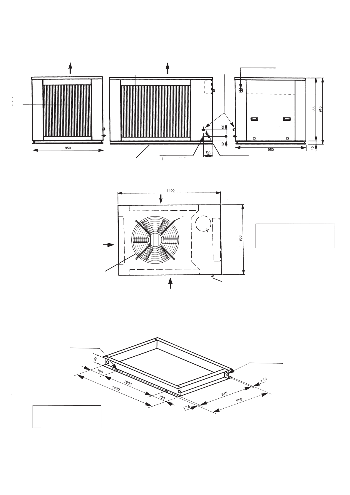
38XTZ 007, 008
Fig. 1 - Dimensions, mm
Outdoor
air inlet
Left-hand side view
Outdoor
air inlet
Outdoor air
discharge
Outdoor air
discharge
Outdoor
air inlet
Refrigerant-air
heat exchanger
Outdoor air
discharge
Compressor
Front view
Refrigerant line
connections
Access
panel
Refrigerant line
connections
Refrigerant line
connections
Outdoor air
discharge
Outdoor air
discharge
Rain water drainage
Access
panel
Main disconnect switch
Power supply
Suction line
connection
1-1/8"
Liquid line
connection 5/8"
Right-hand side view
View A
Outdoor air
discharge
Plan view
View from below
View A - unit base
Front view
Plan view
When designing an installation, always use up-to-date drawings, available from your local Carrier office.
5
38XTZ 011
Fig. 2 - Dimensions, mm
Outdoor
air inlet
Rear view
Outdoor air
discharge
Outdoor
air inlet
Outdoor
air inlet
See view of
unit base
Outdoor air
discharge
Liquid line
connection 5/8"
Left-hand side view
Outdoor
air inlet
Refrigerant-air heat exchanger
Fan
Compressor
Suction line
connection 1-1/8"
Power supply
Control box
Main disconnect switch
Control box
Compressor
access panel
Front view
Note:
Rain water is drained through
the hole under the fan in the
base panel.
Outdoor air
discharge
4 anchor and fixing
holes ø 10 mm
Note:
The unit includes four anchor
holes in the base section.
Refrigerant-air heat exchanger
Outdoor
air inlet
Plan view
Refrigerant line
connections
Profile view - unit base
4 lifting and transport
holes ø 17 mm
When designing an installation, always use up-to-date drawings, available from your local Carrier office.
6

38XTZ 014
Fig. 3 - Dimensions, mm
Outdoor air
discharge
Rear view
Outdoor
air inlet
Outdoor air
discharge
Left-hand side view
Fans
Suction line
connection 1-1/8"
Main disconnect switch
Power supply
Liquid line
connection 5/8"
Control box
Compressor
access panel
Front view
Note:
Rain water is drained through
holes in the lower part of the
base under the outdoor unit
heat exchanger and the fans.
4 anchor and fixing
holes ø 12 mm
Refrigerant-air heat exchanger
Outdoor
air inlet
Plan view
Control box
Compressor
Refrigerant line
connections
Profile view - unit base
4 lifting and transport
holes ø 16 mm
When designing an installation, always use up-to-date drawings, available from your local Carrier office.
7

38XTZ 016, 020 and 024
Fig. 4 - Dimensions, mm
Outdoor
air inlet
Access
panel
Right-side view
Outdoor
air inlet
Fans
Outdoor air
discharge
Outdoor
air inlet
See view A
Outdoor
air inlet
Outdoor
air inlet
Main disconnect switch
Access panel
Power supply
Outdoor air
discharge
Rear view
Suction line
connection 1-1/8"
Outdoor
air inlet
Control box
Compressor
access panel
View A
Note:
The unit includes four anchor
holes in the base section.
Plan view
4 lifting and transport
holes ø 35 mm
Refrigerant line
connections
4 anchor and fixing
holes ø 14 mm
Liquid line
connection 5/8"
Front view
View A
Profile view - unit base
Note:
Rain water is drained through holes in the
lower part of the base under the outdoor unit
heat exchanger and the fans.
When designing an installation, always use up-to-date drawings, available from your local Carrier office.
8
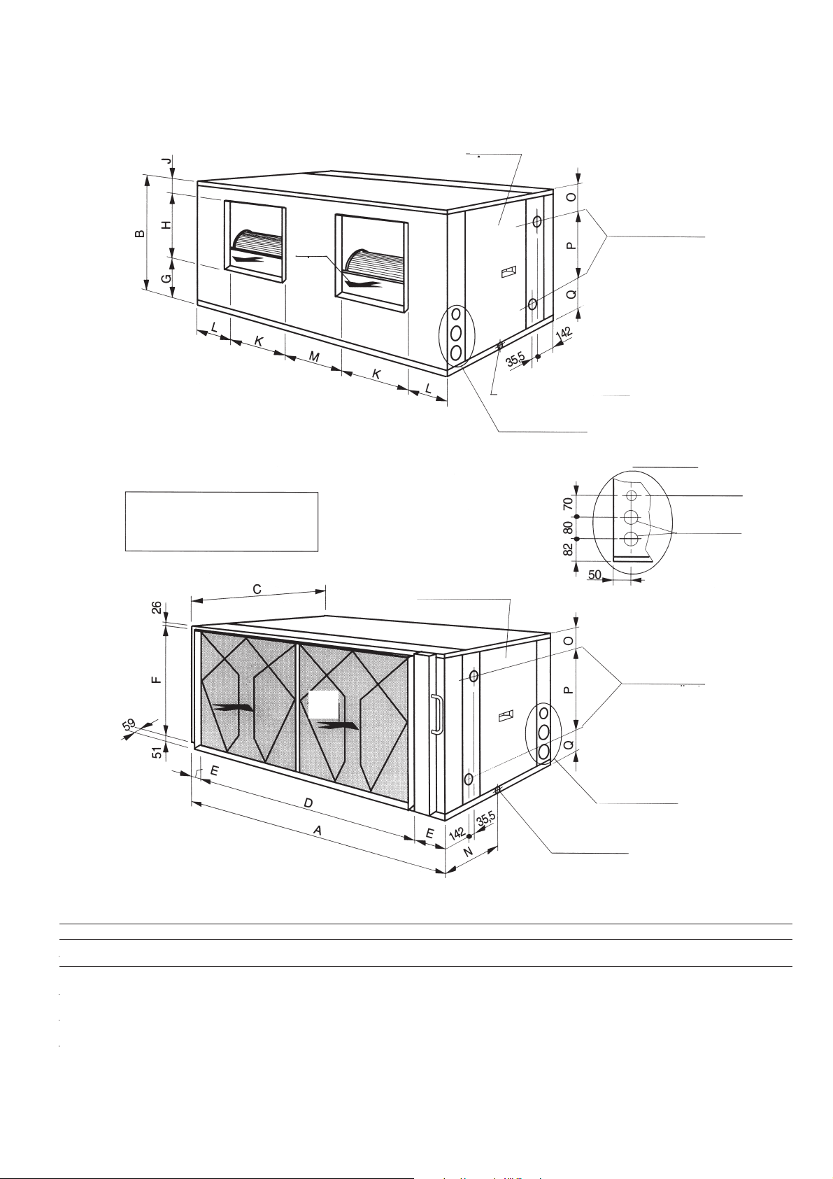
40ABZ/ALZ 007-014
Air
discharge
Fig. 5 - Dimensions, mm
Access panel
Outlet
Hot water coil connections
(accessory/option)
Alternative drain ø 23
Note:
The air discharge can be changed from
horizontal to vertical (see page 26).
Ver página 26
Front and right-side view
Air
inlet
See detail A
Detail A
Electrical connections
Refrigerant line
connections
Access panel
Outlet
Hot water coil connections
(accessory/option)
See detail A
Standard drain ø 23
Rear and left-side view
Dimensions, mm
40ABZ/ALZ ABCDEFGHJ KL MNOPQ
007, 008, 011 1348 662 807 1166 91 585 164 294 204 336 211 254 465 160 331 171
014 1588 788 910 1366 111 711 196 350 242 201 240.5 305 455 203 372 213
Note: Sizes 011 and 014 are 40ALZ.
When designing an installation, always use up-to-date drawings, available from your local Carrier office.
9

40ABZ 016-024
Fig. 6 - Dimensions, mm
Access panel
Outlet
Note:
The air discharge can be changed from
horizontal to vertical (see page 26).
Dimensions, mm
40ABZ A B C
016, 020 2125 1815 507.5
024 2625 2315 757.5
Air
discharge
Front and right-side view
Hot water coil connections
(accessory/option)
Alternative drain ø 23
See detail A
Detail A
Electrical connections
Refrigerant line
connections
Access panel
Air
inlet
Rear and left-side view
When designing an installation, always use up-to-date drawings, available from your local Carrier office.
Outlet
Hot water coil connections
(accessory/option)
See detail A
Standard drain ø 23
10
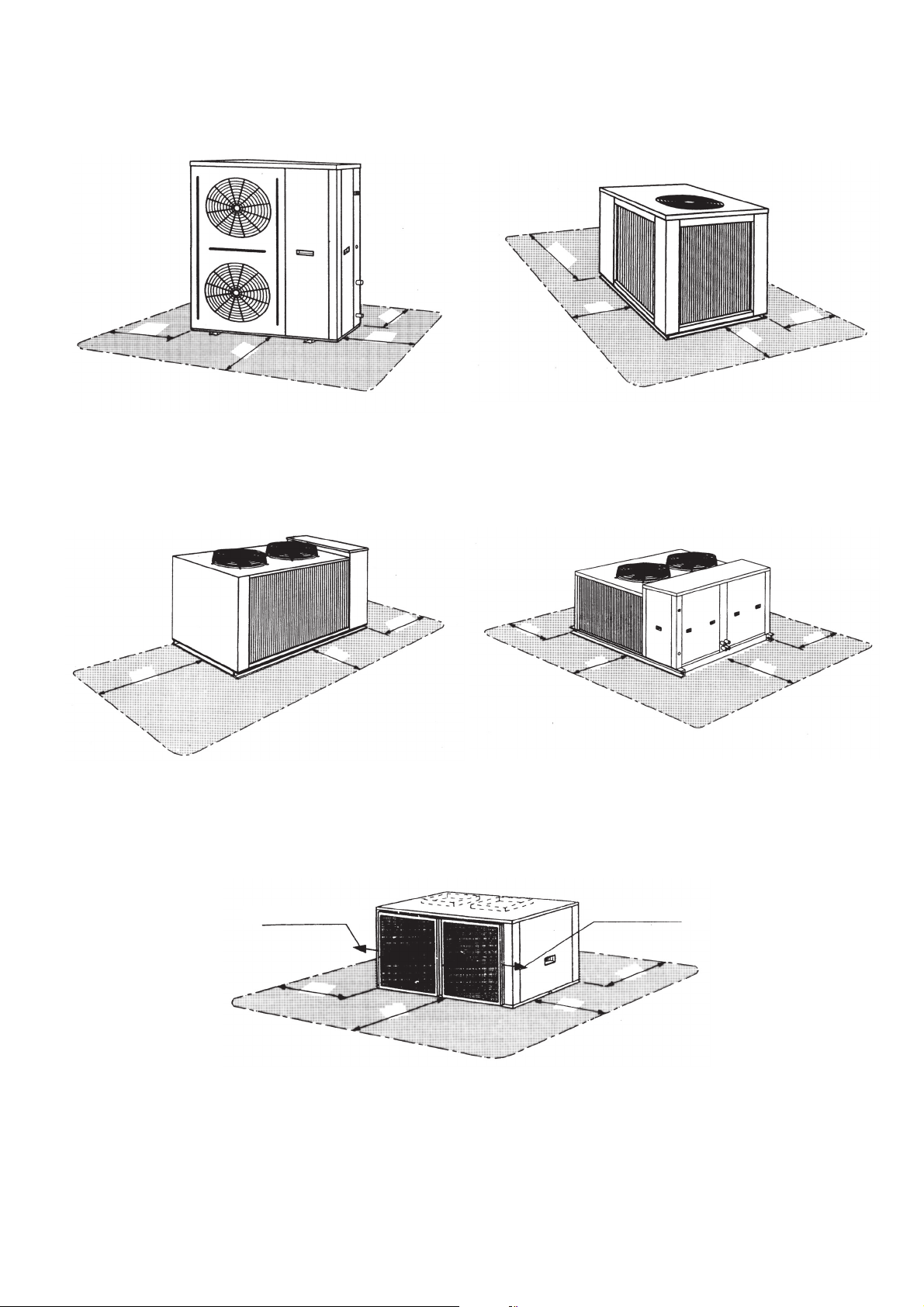
Fig. 7 - Service clearance, mm
38XTZ 007, 008
200
200
500
700
38XTZ 011
1000
500
38XTZ 014 38XTZ 016, 020, 024
500
500
500
40ABZ/ALZ (all sizes)
Air filter removal
(*)
500
1000
600
500
500
Air filter removal
(*)
500
1000
600
* Required service space for the removal of the air filter and the fans (in case of a breakdown). Clearance should be the same as
the unit width.
11
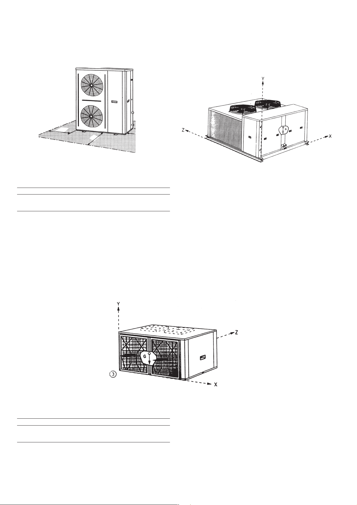
Fig. 8 - Centre of gravity coordinates (mm - approx.)
38XTZ 007 and 008
38XTZ 007 008 011 014 016 020 024
XG* 772 782 564 525 1000 1000 1000
YG* 380 380 412 536 405 431 430
ZG* 173 176 843 741 750 805 420
* Measured from point
38XTZ 011 to 024
40ABZ/ALZ (all sizes)
40ABZ/ALZ 007 008 011* 014* 016 020 024
XG** 943 950 955 1115 1620 1625 1870
YG** 225 225 225 257 230 230 230
ZG** 415 412 415 452 520 520 520
* Models 40ALZ
** Measured from point
12
 Loading...