


39SH,SV,SM,SR00-17
Indoor and Outdoor Air Handlers
Installation, Start-Up and Service Instructions
CONTENTS
Page
SAFETY CONSIDERATIONS . . . . . . . . . . . . . . . . . . . . . 1,2
INTRODUCTION. . . . . . . . . . . . . . . . . . . . . . . . . . . . . . . . . 2-17
Unit Identification . . . . . . . . . . . . . . . . . . . . . . . . . . . . . . . . . . 2
PREINSTALLATION . . . . . . . . . . . . . . . . . . . . . . . . . . . . 18,19
Rigging . . . . . . . . . . . . . . . . . . . . . . . . . . . . . . . . . . . . . . . . . . . 18
Shipping Bolt and Screw Removal . . . . . . . . . . . . . . . . 18
Unit Suspension . . . . . . . . . . . . . . . . . . . . . . . . . . . . . . . . . . 18
Service Clearance . . . . . . . . . . . . . . . . . . . . . . . . . . . . . . . . 18
Condensate Drain. . . . . . . . . . . . . . . . . . . . . . . . . . . . . . . . . 18
External Vibration Isolators . . . . . . . . . . . . . . . . . . . . . . . 18
INSTALLATION. . . . . . . . . . . . . . . . . . . . . . . . . . . . . . . . . 19-33
Condensate Drain. . . . . . . . . . . . . . . . . . . . . . . . . . . . . . . . . 19
Bottom Return Economizer Package (BREP) and
Horizontal Bottom Return Economizer
Package (HBREP). . . . . . . . . . . . . . . . . . . . . . . . . . . . . . . 19
Motorized Outside Air Damper . . . . . . . . . . . . . . . . . . . . 22
Mixing Box Actuator (for 39SH and 39SM Horizontal
Return Units Only) . . . . . . . . . . . . . . . . . . . . . . . . . . . . . . 23
• MIXING BOX ACTUATOR ASSEMBLY
• ACTUATOR INSTALLATION
Mixing Box Air Sensor . . . . . . . . . . . . . . . . . . . . . . . . . . . . 25
• MIXING BOX MIXED AIR SENSOR BRACKET
ASSEMBLY
• MIXED AND OUTSIDE AIR SENSORS
INSTALLATION
Mixing Box. . . . . . . . . . . . . . . . . . . . . . . . . . . . . . . . . . . . . . . . 25
• MIXING BOX LINKAGE INSTALLATION
(39SH Sizes 00-03)
• MIXING BOX LINKAGE INSTALLATION
(Sizes 04-17)
Install Sheaves on Motor and Fan Shafts . . . . . . . . . 27
•ALIGNMENT
Install V-Belts . . . . . . . . . . . . . . . . . . . . . . . . . . . . . . . . . . . . . 28
Water and Steam Coil Piping
Recommendations. . . . . . . . . . . . . . . . . . . . . . . . . . . . . . 29
• GENERAL
• WATER COILS
• STEAM COILS
Coil Freeze-Up Protection. . . . . . . . . . . . . . . . . . . . . . . . . 31
Refrigerant Piping, Direct Expansion
(DX) Coils. . . . . . . . . . . . . . . . . . . . . . . . . . . . . . . . . . . . . . . 32
Electric Heaters. . . . . . . . . . . . . . . . . . . . . . . . . . . . . . . . . . . 33
Motor Stop/Start Stations . . . . . . . . . . . . . . . . . . . . . . . . . 33
START-UP. . . . . . . . . . . . . . . . . . . . . . . . . . . . . . . . . . . . . . . . . 34
Check List . . . . . . . . . . . . . . . . . . . . . . . . . . . . . . . . . . . . . . . . 34
SERVICE . . . . . . . . . . . . . . . . . . . . . . . . . . . . . . . . . . . . . . 34,35
General . . . . . . . . . . . . . . . . . . . . . . . . . . . . . . . . . . . . . . . . . . . 34
Fan Motor Replacement. . . . . . . . . . . . . . . . . . . . . . . . . . . 34
Coil Cleaning . . . . . . . . . . . . . . . . . . . . . . . . . . . . . . . . . . . . . 34
• DETERGENT
Winter Shutdown (Chilled Water Coil Only) . . . . . . . 34
• ANTIFREEZE METHODS OF COIL PROTECTION
• AIR DRYING METHOD OF COIL PROTECTION
•PIPING
Page
Filters . . . . . . . . . . . . . . . . . . . . . . . . . . . . . . . . . . . . . . . . . . . . .35
• FILTER SECTIONS
Lubrication. . . . . . . . . . . . . . . . . . . . . . . . . . . . . . . . . . . . . . . .35
• MOTORS
• BEARINGS
SAFETY CONSIDERATIONS
Air-handling equipment is designed to provide safe and reliable service when operated within design specifications. To
avoid injury to personnel and damage to equipment or property
when operating this equipment, use good judgment and follow
safe practices as outlined below.
DANGER
NEVER enter an enclosed fan cabinet or reach into a unit
while the fan is running.
LOCK OPEN AND TAG the fan motor power disconnect
switch before working on a fan. Take fuses with you and
note removal on tag. Electric shock can cause personal
injury or death.
LOCK OPEN AND TAG the electric heat coil power disconnect switch before working on or near heaters.
Failure to follow these warnings could lead to personal
injury or death.
WARNING
CHECK the assembly and component weights to be
sure that the rigging equipment can handle them safely.
Note also, the centers of gravity and any specific rigging
instructions.
CHECK for adequate ventilation so that fumes will not
migrate through ductwork to occupied spaces when welding or cutting inside air-handling unit cabinet or plenum.
WHEN STEAM CLEANING COILS be sure that the area
is clear of personnel.
DO NOT attempt to handle access covers and removable
panels on outdoor units when winds are strong or gusting
until you have sufficient help to control them. Make sure
panels are properly secured while repairs are being made to
a unit.
DO NOT remove access panel fasteners until fan is completely stopped. Pressure developed by a moving fan can
cause excessive force against the panel which can injure
personnel.
DO NOT work on dampers until their operators are
disconnected.
BE SURE that fans are properly grounded before working
on them.
Failure to follow these warnings could result in personal
injury or equipment damage.
Manufacturer reserves the right to discontinue, or change at any time, specifications or designs without notice and without incurring obligations.
Catalog No. 04-53390006-01 Printed in U.S.A. Form 39S-2SI Pg 1 614 7-08 Replaces: 39S-1SI
CAUTION
Unit Identification — The 39S units are identified by
INTRODUCTION
the 18-digit part number listed on the serial plate. The part
SECURE drive sheaves with a rope or strap before working on a fan to ensure that rotor cannot free-wheel.
DO NOT restore power to unit until all temporary walkways inside components have been removed.
NEVER pressurize equipment in excess of specified test
pressures.
PROTECT adjacent flammable material when welding or
number describes all component, coil, motor, drive, and control
selections.
For further information on unit and component identification, contact your Carrier representative for the AHUBuilder
program. Refer to the 39S Product Data catalog for more information on individual component sections. Refer to Tables 1-4
and Fig. 1-13 for component data.
flame cutting. Use sheet metal or asbestos cloth to contain
sparks. Have a fire extinguisher at hand and ready for
immediate use.
Failure to follow these warnings could result in personal
injury or equipment damage.
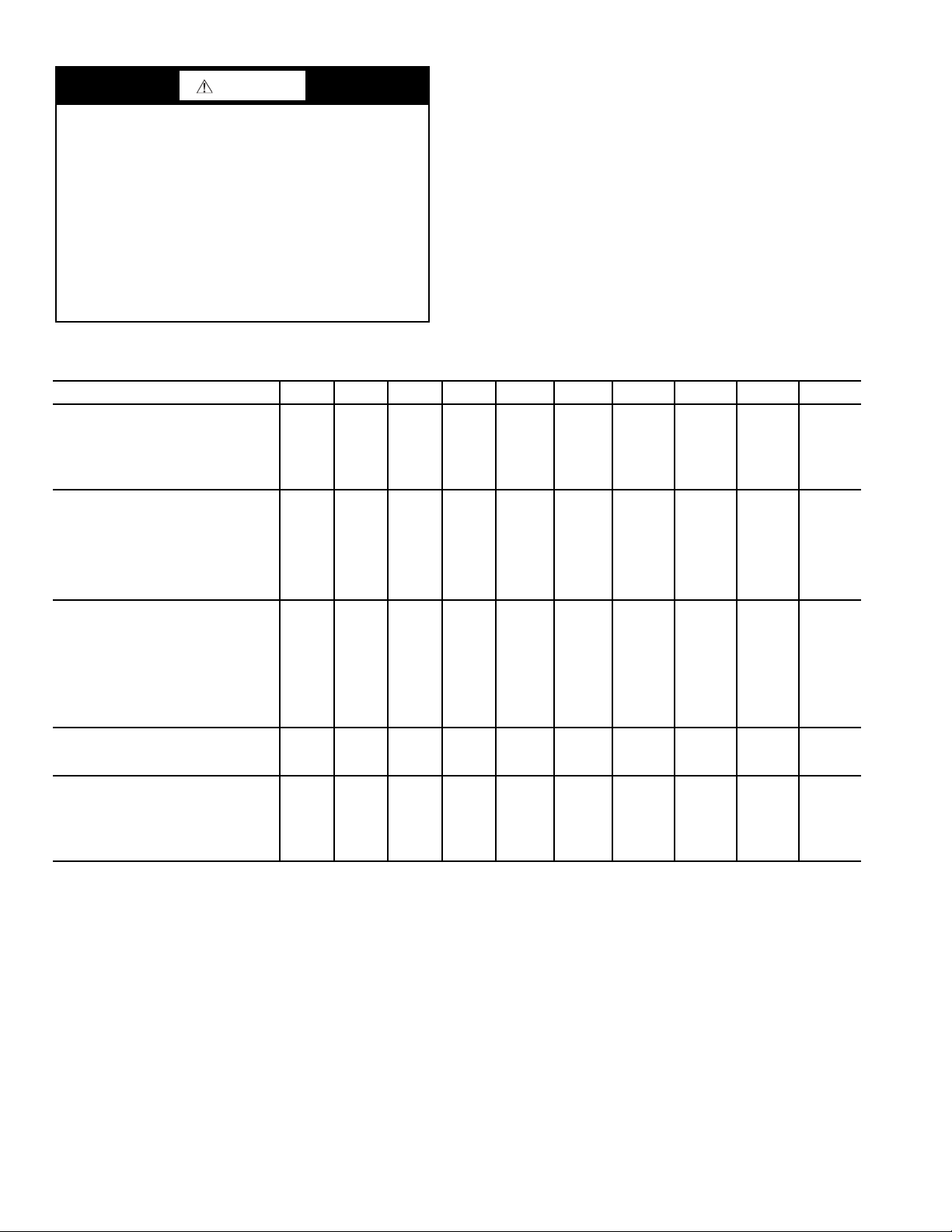
Table 1 — Physical Data — 39SH Coil and Filter Data
39SH UNIT SIZE 00 01 02 03 04 05 07 09 13 17
CHILLED WATER
Nominal Capacity at 400 fpm (cfm) 632 716 800 1224 1612 2000 2916 3832 5500 7084
Face Area (sq ft) 1.58 1.79 2 3.06 4.03 5 7.29 9.58 13.75 17.71
Coil Connection Size (in. OD sweat)
4 Row (Qty)
6 Row (Qty)
HOT WATER
Nominal Capacity at 400 fpm (cfm) 632 716 624 956 1612 2000 2688 3544 5348 6640
Face Area (sq ft) 1.58 1.79 1.56 2.39 4.03 5 6.72 8.86 13.37 16.6
Coil Connection Size (in. OD sweat)
1 Row
2 Row (Qty)
4 Row* (Qty)
6 Row* (Qty)
DIRECT EXPANSION
Nominal Capacity at 400 fpm (cfm) 452 476 820 1220 1612 2000 2864 4088 5500 6640
Face Area (sq ft) 1.13 1.19 2.05 3.05 4.03 5 7.16 10.22 13.75 16.6
Connection Size (in. OD sweat)
(Qty)
Liquid Line
Suction Line
STEAM
Nominal Capacity at 400 fpm (cfm) 632 716 752 1144 1452 1800 2688 3640 5512 7000
Face Area (sq ft) 1.58 1.79 1.88 2.86 3.63 4.5 6.72 9.1 13.78 17.5
FI LT ER D ATA
Size (in.) (Qty) 12x25 12x25 16x32 16x32 20x20
Nominal Face Area (sq ft) 2.08 2.08 3.56 3.56 5.56 5.56 11.56 11.56 18.06 22.5
*4 and 6 row hot water coils have the same face area as 4 and 6 row
chilled water coils.
†Single circuited coil.
**Dual circuited coil.
3
/
3
/
5
/
7
/
3
/
3
/
1
/
3
/
3
4
4
8
8
4
4
4
4
/
3
/
5
/
7
/
3
/
3
/
1
/
3
/
3
4
4
8
8
4
4
4
4
/
3
/
5
/
7
/
3
/
3
/
3
/
3
/
3
4
4
8
8
4
4
8
4
/
4
7
/
8
5
/
8
7
/
8
3
/
4
7
/
8
3
/
8
3
/
4
11/
11/
7
7
7
7
1
7
(2)
/
/
/
/
/
/
11/
8
11/
8
7
11/
11/
11/
11/
/
8
1
/
2
8
8
8
8
2
8
20x20
(2)
11/
8
8
8
8
8
8
8
13/
8
N/A N/A N/A N/A
11/
8
11/
8
13/
8
5
/8†,
1
/2** (2)
11/8†,
7
/8** (2)
16x32 (2)
20x32 (1)
13/
8
15/
8
13/
8
13/
8
15/
8
5
/8†,
1
/2** (2)
13/8†,
7
/8** (2)
16x32 (2)
20x32 (1)
13/
15/
13/
13/
15/
1
/2** (2) 5/8** (2)
15/8 (2)
8
15/8 (2)
8
15/8 (2)
8
15/8 (2)
8
15/8 (2)
8
11/8** (2) 13/8** (2)
20x25 (2)
20x20 (4)
16x20 (2)
16x25 (2)
20x20 (2)
20x25 (2)
®
2
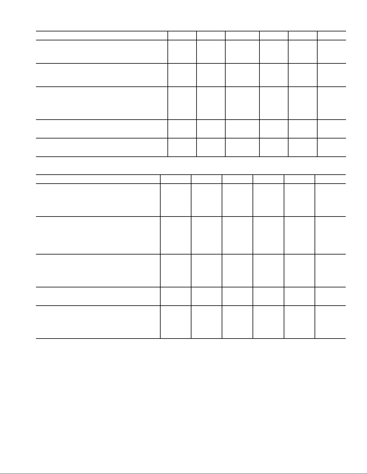
Table 2 — Physical Data — 39SV Coil and Filter Data
39SV UNIT SIZE 02 03 04 05 07 09
CHILLED WATER
Nominal Capacity at 400 fpm (cfm) 1200 1200 1600 2000 2932 3668
Face Area (sq ft) 3 3 4 5 7.33 9.17
Coil Connection Size (in. OD sweat)
3
/
4
3
/
4
7
/
8
11/
8
11/
8
HOT WATER
Nominal Capacity at 400 fpm (cfm) 804 804 964 1276 2292 3124
Face Area (sq ft) 2.01 2.01 2.41 3.19 5.73 7.81
Coil Connection Size (in. OD sweat)
7
/
8
7
/
8
7
/
8
11/
8
11/
8
DIRECT EXPANSION
Nominal Capacity at 400 fpm (cfm) 1200 1200 1600 2000 2932 3668
Face Area (sq ft) 3 3 4 5 7.33 9.17
Connection Size (in. OD sweat) (Qty)
Liquid Line
Suction Line
3
/
8
3
/
4
3
/
8
3
/
4
1
/
2
7
/
8
11/
1
/
2
8
5/8
11/
8
STEAM
Nominal Capacity at 400 fpm (cfm) 624 624 688 1268 1750 2452
Face Area (sq ft) 1.56 1.56 1.72 3.17 4.375 6.13
FI LT ER D ATA
Size (in.) (Qty) 20x20 20x20 22.5x22.5 16x25 (2) 20x25 (4) 20x25 (4)
Nominal Face Area (sq ft) 2.78 2.78 3.52 5.56 13.89 13.89
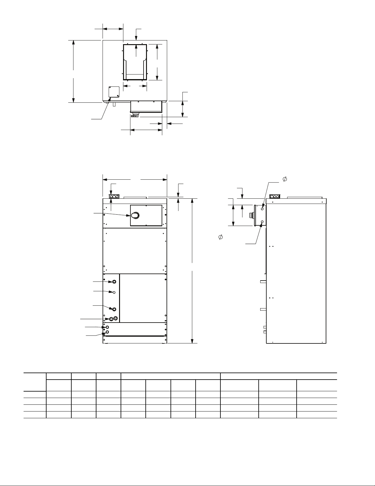
Table 3 — Physical Data — 39SM Coil and Filter Data
39SM UNIT SIZE 04 05 07 09 13 17
CHILLED WATER
Nominal Capacity at 400 fpm (cfm) 1668 2084 2776 3332 5000 7084
Face Area (sq ft) 4.17 5.21 6.94 8.33 12.5 17.71
Coil Connection Size (in. OD sweat)
4 Row (Qty)
6 Row (Qty) 11/
HOT WATER
Nominal Capacity at 400 fpm (cfm) 1668 2084 2776 3332 5000 7084
Face Area (sq ft) 4.17 5.21 6.94 8.33 12.5 17.71
Coil Connection Size (in. OD sweat)
2 Row (Qty)
4 Row* (Qty)
6 Row* (Qty) 11/
DIRECT EXPANSION
Nominal Capacity at 400 fpm (cfm) 1668 2000 2668 3332 5000 7000
Face Area (sq ft) 4.17 5 6.67 8.33 12.5 17.5
Connection Size (in. OD sweat)
Liquid Line
Suction Line
STEAM
Nominal Capacity at 400 fpm (cfm) 1492 1960 2472 3028 4752 6700
Face Area (sq ft) 3.73 4.9 6.18 7.57 11.88 16.75
FI LT ER D ATA
Size (in.) (Qty) 20x25 (2) 20x25 (2) 16x25 (4) 16x25 (4) 16x20 (2)
Nominal Face Area (sq ft) 6.94 6.94 11.11 11.11 22.5 22.5
*4 and 6 row hot water coils have the same face area as 4 and 6 row
chilled water coils.
7
/
8
8
7
/
8
7
/
8
8
1
/
2
7
/
8
11/
11/
11/
11/
11/
11/
8
8
8
8
8
1
/
2
8
11/
13/
11/
11/
13/
11/
8
8
8
8
8
5
/
8
8
13/
15/
11/
13/
15/
13/
8
8
8
8
8
5
/
8
8
13/
8
15/
8
11/
8
13/
8
15/
8
5
/
8
13/
8
20x20 (2)
16x25 (2)
20x25 (2)
15/8 (2)
15/8 (2)
11/8 (2)
15/8 (2)
15/8 (2)
15/8 (2)
16x20 (2)
20x20 (2)
16x25 (2)
20x25 (2)
13/
11/
1
/2 (2)
7
/8 (2)
5
/8 (2)
8
8
3
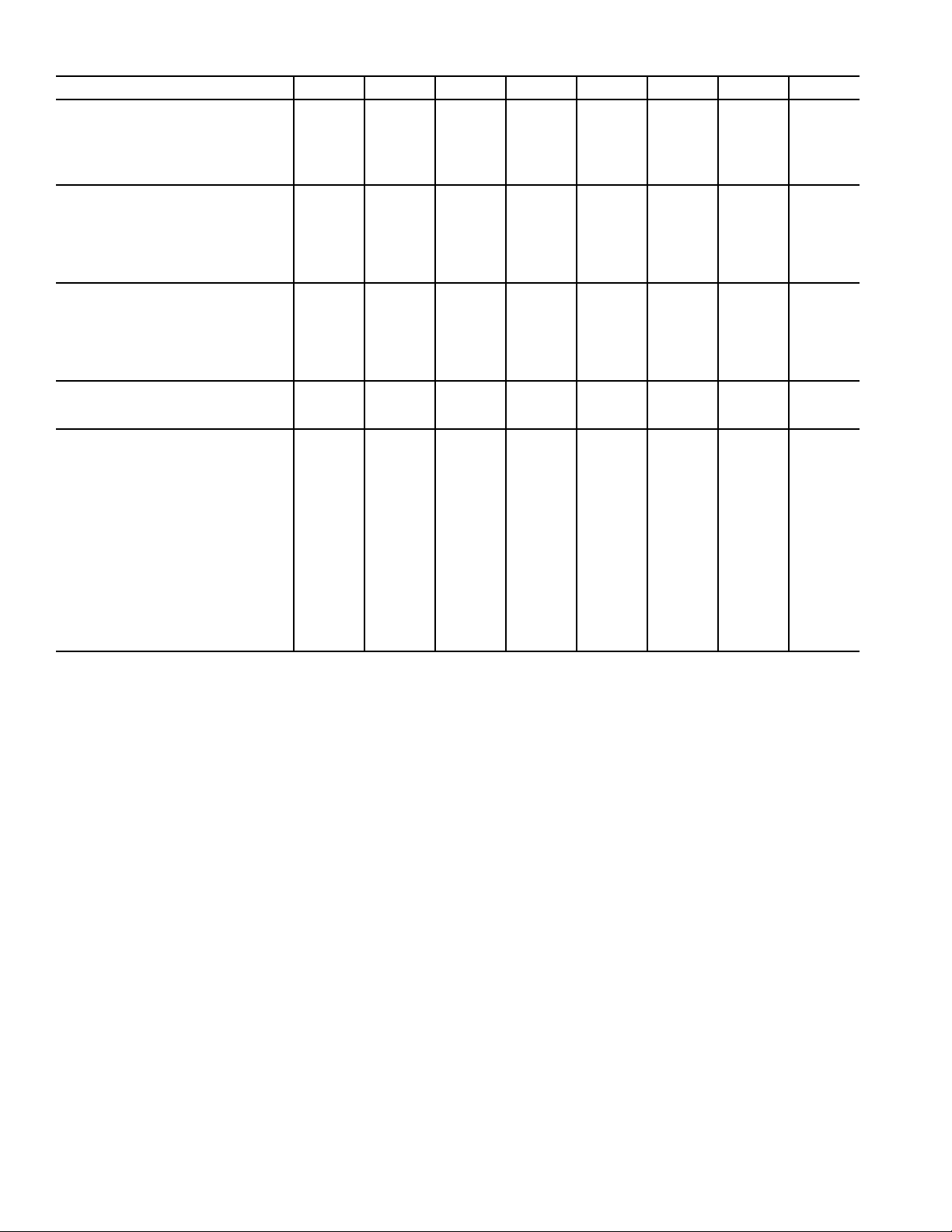
Table 4 — Physical Data — 39SR Coil and Filter Data
39SR UNIT SIZE 02 03 04 05 07 09 13 17
CHILLED WATER
Nominal Capacity at 400 fpm (cfm) 800 1224 1612 2000 3252 3792 5124 7000
Face Area (sq ft) 2 3.06 4.03 5 8.13 9.48 12.81 17.5
Coil Connection Size (in. OD sweat)
4 Row
6 Row
3
/
4
3
/
4
HOT WATER
Nominal Capacity at 400 fpm (cfm) 624 956 1612 2000 3252 3792 5124 7000
Face Area (sq ft) 1.56 2.39 4.03 5 8.13 9.48 12.81 17.5
Coil Connection Size (in. OD sweat)
2 Row
4 Row*
6 Row*
5
/
8
3
/
4
3
/
4
DIRECT EXPANSION
Nominal Capacity at 400 fpm (cfm) 800 1224 1612 2000 3252 3792 5124 7000
Face Area (sq ft) 2 3.06 4.03 5 8.13 9.48 12.81 17.5
Connection Size (in. OD sweat)
(Qty)
Liquid Line
Suction Line
3
/
8
3
/
4
STEAM
Nominal Capacity at 400 fpm (cfm) 752 1144 1452 1800 3088 3576 4956 6768
Face Area (sq ft) 1.88 2.86 3.63 4.5 7.72 8.94 12.39 16.92
FI LT ER D ATA
Single Wall Unit, Throwaway Filter
Size (in.) (Qty) 16x32 16x32 20x20 (2) 20x20 (2) 16x25 (4) 16x25 (4) 16x20 (3)
Nominal Face Area (sq ft) 3.56 3.56 5.56 5.56 11.11 11.11 15 20
Single Wall Unit, Pleated Filter
Size (in.) (Qty) 16x32 16x32 20x24 (1)
Nominal Face Area (sq ft) 3.56 3.56 5.56 5.56 11.11 11.11 15 20
Double Wall Unit,
Pleated and Throwaway Filters
Size (in.) (Qty) 16x32 (1)
10x10 (3)
Nominal Face Area (sq ft) 5.64 5.64 8.75 8.75 15.63 15.63 17.67 23.11
*4 and 6 row hot water coils have the same face area as 4 and 6 row
chilled water coils.
3
/
4
7
/
8
7
/
8
3
/
4
7
/
8
3
/
8
3
/
4
16x32 (1)
10x10 (3)
7
/
8
11/
8
7
/
8
7
/
8
11/
8
1
/
2
7
/
8
16x20 (1)
12x25 (1)
12x20 (1)
16x20 (1)
16x25 (1)
11/
8
11/
8
11/
8
11/
8
11/
8
1
/
2
11/
8
20x24 (1)
16x20 (1)
12x25 (1)
12x20 (1)
16x20 (1)
16x25 (1)
13/
15/
11/
13/
15/
11/
8
8
8
8
8
5
/
8
8
13/
15/
11/
13/
15/
13/
8
8
8
8
8
5
/
8
8
13/
8
15/
8
13/
8
13/
8
15/
8
7
/8 (2)
13/8 (2) 15/8 (2)
16x25 (3)
16x25 (4) 16x25 (4) 16x20 (3)
25x25 (2)
20x25 (2)
25x25 (2)
20x25 (2)
16x25 (3)
16x24 (3)
29x48 (1)
13/
8
15/
8
11/
8
13/
8
15/
8
7
/8 (2)
16x20 (4)
16x25 (4)
16x20 (4)
16x25 (4)
16x20 (4)
16x32 (4)
4
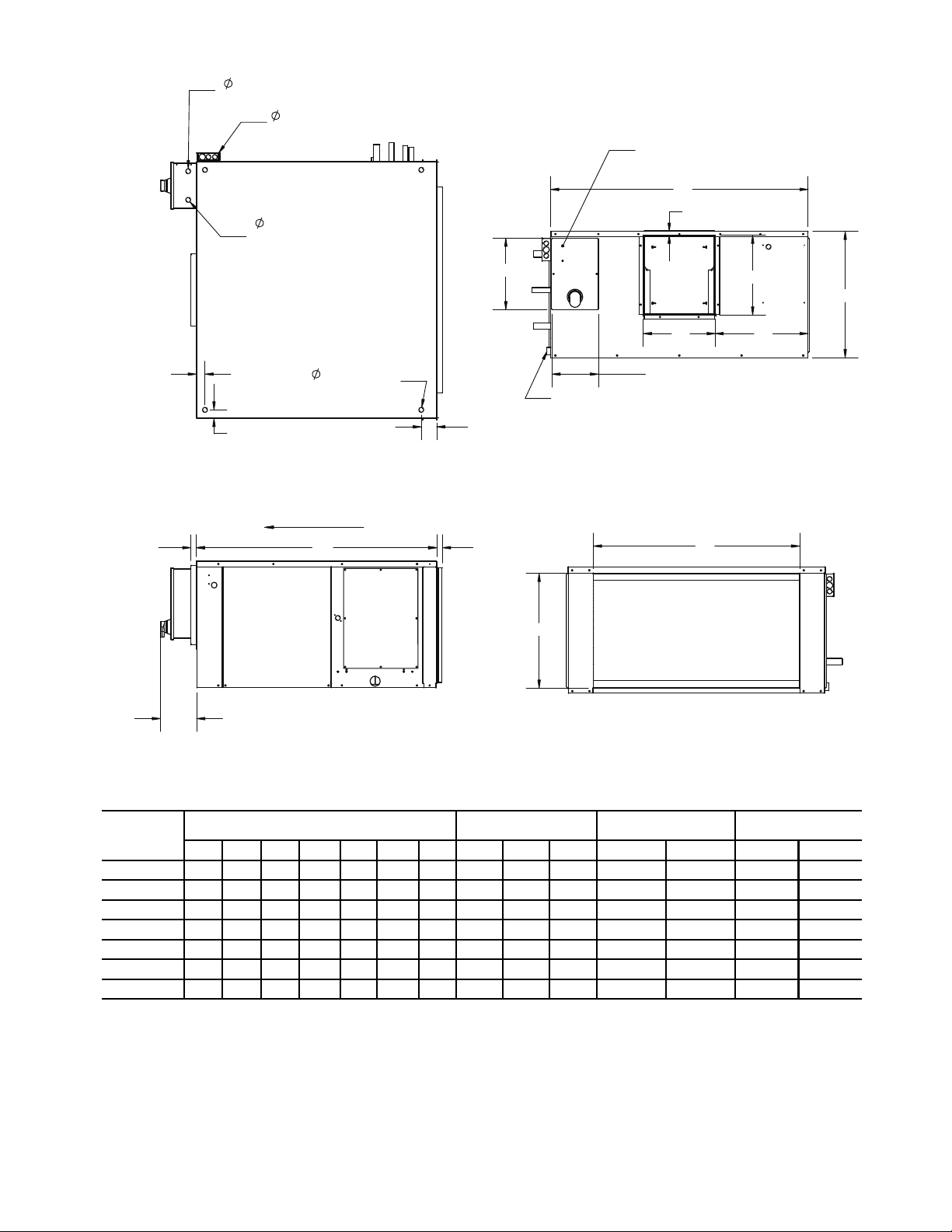
DIMENSIONS (in.)
LEGEND
*"C1" dimension is for standard unit. "C2" dimension is for double wall units.
†Sizes 13 and 17 are twin blowers. Dimension "E" is to closest blower. Dimension "F" and "G" are typical for both fan outlets.
NOTES:
1. Measurements shown in inches.
2. Unit hand is determined by looking into the filters in same direction as airflow. Right hand unit shown for reference.
39SH UNIT
SIZE
UNIT OUTLINE UNIT MOUNTING
BLOWER OPENING
OUTLET
RETURN DUCT
CONNECTION
A B C1* C2* D E H M N P F G K L
00,01
38.0
28.0 14.1 15.1 1.0 9.6 1.0 1.6 2.6 3.3 8.6 10.6 22.0 12.3
02,03
37.1
36.6 18.1 19.0 1.0 14.1 1.0 1.5 1.5 2.9 8.4 10.6 27.6 16.4
04 42.0 45.0 22.1 23.0 1.0 17.9 1.0 1.5 1.5 2.7 9.1 13.8 36.0 20.0
05 42.0 45.0 22.1 23.0 1.0 14.3 1.0 1.5 1.5 2.7 12.5 13.8 36.0 20.0
07,09 52.5 57.0 34.8 34.8 1.0 21.8 9.1 2.8 2.8 2.8
13.4
16.2 48.0 32.2
13 57.5 67.2 43.0 43.0 N/A 11.4† 8.0 3.7 3.7 3.7 16.4
†
(2) 16.4† (2) 57.9 40.4
17 57.5 72.3 48.0 48.0 N/A 14.0
†
13.0 3.7 3.7 3.7 16.4
†
(2) 16.4
†
(2) 66.0 45.7
BTM — Bottom
KO — Knockout
w/o MSS — Without Motor Start/Stop Station
Fig. 1 — 39SH Unit
Airflow
Top View
Left Side View
FILTER
Front View
Rear View
L
K
Motor Start/Stop
Station (opt)
12.51
H
B
C1-2
*
F
G
E
8.12
A
6.35
DD
.875 Power Conn. (w/o MSS)
3/4" FPT
Drain Conn.
(TYP)
P
KO (TYP)
(TOP/BTM)
.875(OPP SIDE)
.875
M (TYP)
(TYP)
Power Conn.
N
.875 24V
Control
Conn.
a39-4122
5
614
DIMENSIONS (in.)
LEGEND
NOTE: Measurements shown in inches.
39SV
UNIT
SIZE
WIDTH DEPTH HEIGHT SUPPLY DUCT CONNECTION SIZES (OD)
A B C D E F G
CW
Supply-ReturnHWSupply-ReturnDXLiquid-Suction
02 22.3 24.0 50.0 6.9 8.5 3.0 11.8
3
/4 - 3/
4
7
/8 - 7/
8
3
/8 - 3/
4
03 22.3 24.0 50.0 6.9 8.5 3.0 11.8
3
/4 - 3/
4
7
/8 - 7/
8
3
/8 - 3/
4
04 25.1 24.3 56.5 8.0 9.1 1.6 13.9
7
/8 - 7/
8
7
/8 - 7/
8
1
/2 - 7/
8
05 29.5 26.0 59.5 8.4 12.6 1.3 13.9 1 1/8 - 1 1/
8
1 1/8 - 1 1/
8
1
/2 - 1 1/
8
CW — Chilled Water MSS — Motor Start/Stop Station
DX — Direct Expansion w/o — Without
HW — Hot Water
D
a39-4065
Fig. 2 — 39SV Unit Sizes 02-05 — Pre-Heat
F
B
4 x 4
J-Box (w/o MSS)
Motor Start/Stop
(MSS) (optional)
12.5
E
Top View
A
1.5
G
6.3
1.9
.8
8.2
24V Control
Conn.
2.5
.875
.875 (OPP SIDE)
Power Conn.
C
Supply Conn. (CW)
Liquid Conn. (DX)
Suction (DX)/
Return (CW)
Conn.
Cond Drain
w/ Aux (3/4" FPT)
Supply Conn. (HW)
Return (HW) Conn.
Front View
6
Right View
DIMENSIONS (in.)
LEGEND
NOTE: Measurements shown in inches.
39SV UNIT SIZE
CONNECTION SIZES (OD)
CW
Supply-ReturnHWSupply-ReturnDXLiquid-Suction
Drain
07 1 1/8 - 1 1/
8
1 1/8 - 1 1/
8
5
/8 - 1 1/
8
0.875
09 1 3/8 - 1 3/
8
1 1/8 - 1 1/
8
1
/2 - 7/8 (2)
0.875
CW — Chilled Water MSS — Motor Start/Stop Station
DX — Direct Expansion w/o — Without
HW — Hot Water
Motor Start/
Stop (opt)
31.00
Iso View
(w/o panels)
Front View
Right View
Top View
4 x 4
J-Box
(w/o MSS)
Power Conn..875
20.316.3
13.3
.875 24V Control Conn.
6.3
2.4
34.2
54.0
(DX) Conn.
20.5
2.3
Return (CW) / Liquid
2.0
1.5
Drain Conn.
Supply Conn. (HW)
Supply (CW) / Suction
10.1
84.4
19.5
.9
(DX) Conn.
Return Conn. (HW)
a39-4066
Fig. 3 — 39SV Unit Sizes 07-09 — Pre-Heat
7

Return Conn. (HW)
Suction (DX)
(MSS) (optional)
/Return (CW) Conn.
Liquid Conn. (DX)
Front View
Supply Conn. (CW)
Top View
Supply Conn. (HW)
Motor Start/Stop
Cond Drain w/ Aux
(3/4" FPT)
A
C
.8
1.5
4 x 4
J-BOX (w/o MSS)
B
E
F
G
D
12.5
6.3
1.9
Right View
2.5
Conn.
24V Control
.875
8.2
.875 (OPP SIDE)
Power Conn.
DIMENSIONS (in.)
LEGEND
NOTE: Measurements shown in inches.
39SV
UNIT
SIZE
WIDTH DEPTH HEIGHT SUPPLY DUCT CONNECTION SIZES (OD)
A B C D E F G
CW
Supply-ReturnHWSupply-ReturnDXLiquid-Suction
02 22.3 24.0 50.0 6.9 8.5 3.0 11.8
3
/4 - 3/
4
7
/8 - 7/
8
3
/8 - 3/
4
03 22.3 24.0 50.0 6.9 8.5 3.0 11.8
3
/4 - 3/
4
7
/8 - 7/
8
3
/8 - 3/
4
04 25.1 24.3 56.5 8.0 9.1 1.6 13.9
7
/8 - 7/
8
7
/8 - 7/
8
1
/2 - 7/
8
05 29.5 26.0 59.5 8.4 12.6 1.3 13.9 1 1/8 - 1 1/
8
1 1/8 - 1 1/
8
1
/2 - 1 1/
8
CW — Chilled Water HW — Hot Water
DX — Direct Expansion w/o MSS— Without Motor Start/Stop Station
a39-4067
Fig. 4 — 39SV Unit — Re-Heat
8

DIMENSIONS (in.)
LEGEND
NOTES:
1. Measurements shown in inches.
2. Hand connections are defined by looking at the filters in the direction of airflow.
3. Coil section and blower ship separately and are installed by others.
4. Blower section may be rotated 180 degrees to relocate supply duct.
39SM
UNIT
SIZE
WIDTH HEIGHT DEPTH
COIL
SECTION
BLOWER
SECTION
MOTOR
START/STOP
(OPT.)
RETURN DUCT
SUPPLY DUCT
(BLOWER OPENING)
SUPPLY
CONN.
RETURN
CONN.
DRAIN
A B C D E F G H I J K L M N O P Q R
04 40.0 53.5 26.0 27.5 26.0 2.8 9.0 36.0 25.5 1.0 2.0 13.6 11.9 1.1 13.1 3.6 20.0 15.2
05 40.0 53.5 26.0 27.5 26.0 2.8 9.0 36.0 25.5 1.0 2.0 13.6 11.9 1.1 13.1 3.6 25.0 15.2
07 50.0 68.5 34.0 34.5 34.0 6.8 13.0 48.0 32.0 1.0 1.0 13.4 16.2 1.2 18.3 3.6 25.0 22.5
09 50.0 68.5 34.0 34.5 34.0 6.8 13.0 48.0 32.0 1.0 1.0 13.4 16.2 1.2 18.3 3.6 30.0 22.5
13 72.0 81.5 34.0 47.5 34.0 6.7 13.0 66.0 45.0 2.0 6.0 16.4 16.4 1.1 14.0 3.6 30.0 23.0
17 72.0 81.5 34.0 47.5 34.0 6.7 13.0 66.0 45.0 2.0 6.0 16.4 16.4 1.1 14.0 3.6 42.6 23.0
CW — Chilled Water
HW — Hot Water
w/o MSS — Without Motor Start/Stop Station
AIR
FILTERS
FLOW
MOTOR
START/STOP (MSS)
(OPT)
H
I
A
K
J
12.51
6.35
VIEWREAR
VIEW
SIZES 04-09
RIGHT
TOP VIEW
CONTROL CONN.
O
.875 24V
L
M
O
N
POWER CONN.
.875 (OPP SIDE)
O
M
L
O
L
N
ACCESS PANEL
C
S
AREA
E
SUPPLY AREA
C
RETURN
S
F
I
L
T
E
R
A
CW/HW
CW/HW
3/4" FPT DRAIN
G
B
P
.98
C
8.18
F
R
Q
.95
D
E
J-BOX (W/O MSS)
.875 POWER
CONN. 4X4
TOP VIEW
SIZES 13, 17
a39-4075
Fig. 5 — 39SM Unit Sizes 04-17 (Vertical Configuration)
9
614

a39-4078
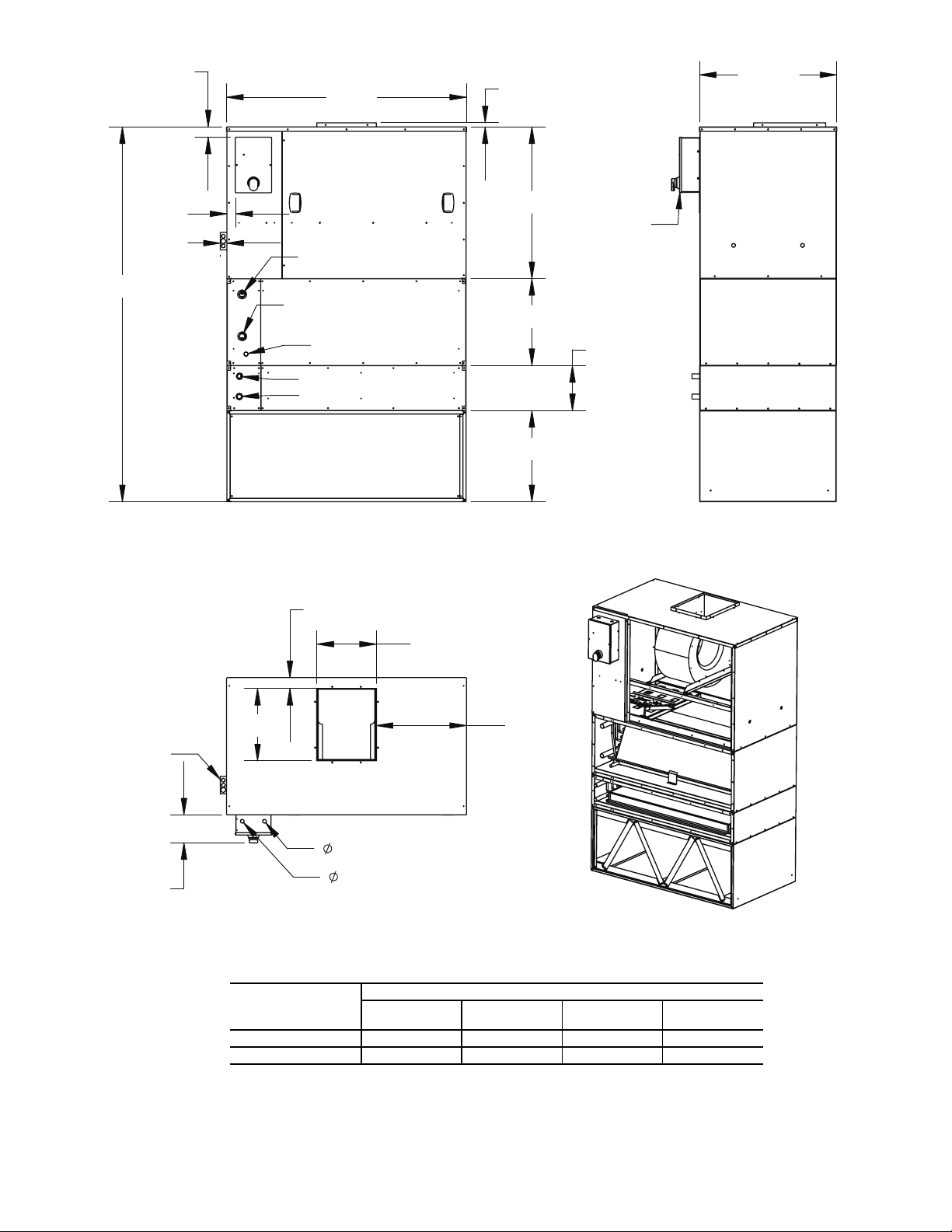
DIMENSIONS (in.)
LEGEND
NOTES:
1. Measurements shown in inches.
2. Hand connections are defined by looking at the filters in the direction of airflow.
3. Coil section and blower ship separately and are installed by others.
4. Blower section may be rotated 180 degrees to relocate supply duct.
39SM
UNIT
SIZE
WIDTH HEIGHT DEPTH
COIL
SECTION
BLOWER
SECTION
MOTOR
START/STOP
(OPT.)
RETURN DUCT
SUPPLY DUCT
(BLOWER OPENING)
SUPPLY
CONN.
RETURN
CONN.
DRAIN
A B C D E F G H I J K L M N O P Q R
04 40.0 27.5 52.0 27.5 26.0 2.7 8.9 36.0 25.5 1.0 2.0 13.6 11.9 1.1 13.1 3.6 20.0 15.2
05 40.0 27.5 52.0 27.5 26.0 2.7 8.9 36.0 25.5 1.0 2.0 13.6 11.9 1.1 13.1 3.6 25.0 15.2
07 50.0 34.5 68.0 34.5 34.0 6.8 12.9 48.0 32.0 1.0 1.0 13.4 16.2 1.2 18.3 3.6 25.0 22.5
09 50.0 34.5 68.0 34.5 34.0 6.8 12.9 48.0 32.0 1.0 1.0 13.4 16.2 1.2 18.3 3.6 30.0 22.5
13 72.0 47.5 68.0 47.5 34.0 6.7 12.9 66.0 45.0 1.0 2.9 16.4 16.4 1.1 14.0 3.6 30.0 23.0
17 72.0 47.5 68.0 47.5 34.0 6.7 12.9 66.0 45.0 1.0 2.9 16.4 16.4 1.1 14.0 3.6 42.6 23.0
CW — Chilled Water
HW — Hot Water
w/o MSS — Without Motor Start/Stop Station
Fig. 6 — 39SM Unit Sizes 04-17 (Horizontal Configuration)
614
10
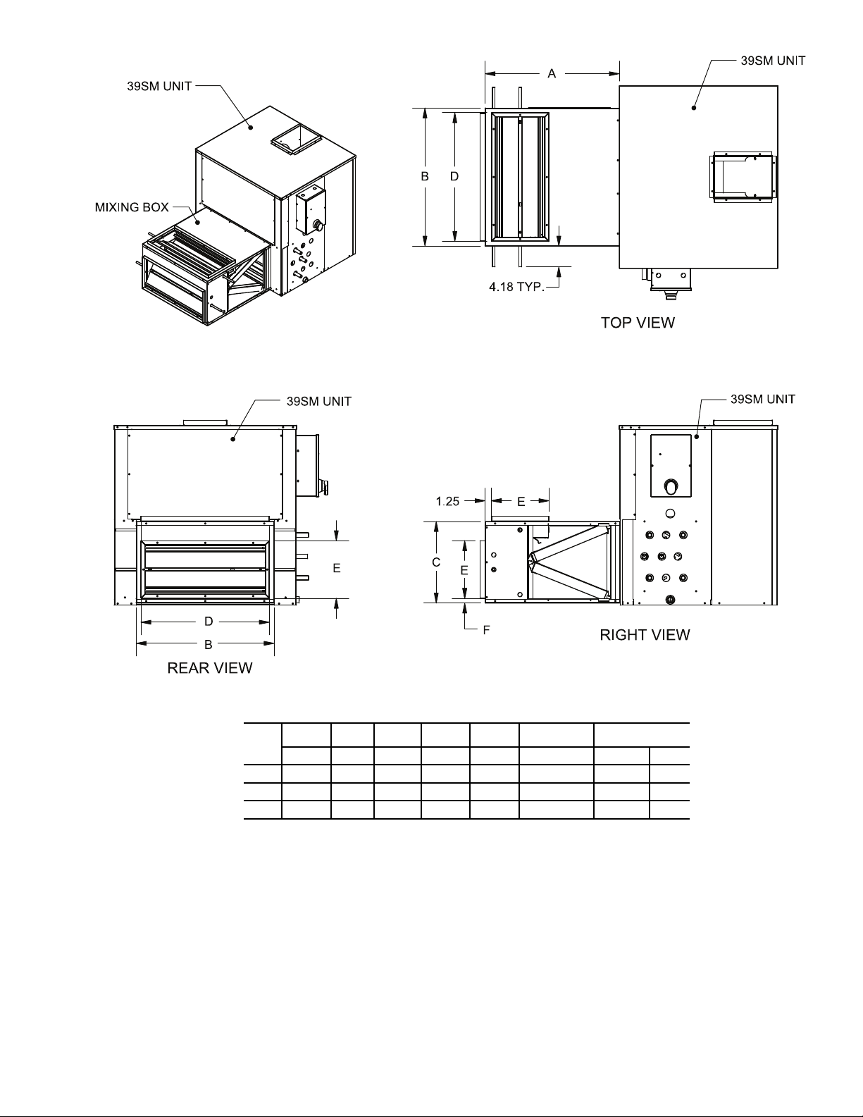
DIMENSIONS (in.)
NOTES:
1. Measurements shown in inches.
2. 39SM unit shown for reference only.
3. Not all components shown for clarity.
4. Optional actuator not shown.
5. Top and rear inlets shown. Bottom and rear inlets are also available.
39SM
UNIT
SIZE
LENGTH WIDTH HEIGHT
DUCT
WIDTH
DUCT
HEIGHT
TOP
CLEARANCE
FILTERS
A B C D E F SIZE QTY
04,05 27.0 36.2 25.5 34.3 15.0 2.0 16 x 32 x 2 2
07,09 32.0 48.2 32.4 46.3 15.0 9.7 20 x 24 x 2 4
13,17 40.0 66.2 45.0 64.3 16.0 15.5 30 x 20 x 2 6
a39-4079
Fig. 7 — 39SM Unit — Mixing Box
11

M
C
B
L
P
HORIZONTAL
DISCHARGE (OPT)
G
F
NO
A
4.0
H
D
F
G
J
K
E
4.0
4.0
DIMENSIONS (in.)
NOTE: Measurements shown in inches.
39SR
UNIT SIZE
A B C D E F G H J K L M N O P
02, 03 67.4 39.6 22.5 12.0 25.8 11.9 8.9 11.0 8.0 35.4 14.2 28.4 2.5 15.3 5.6
04, 05 72.1 48.1 28.5 12.0 34.0 14.1 13.1 11.0 8.0 35.6 18.2 35.8 5.1 17.5 6.2
07, 09 75.0 53.0 42.2 14.0 44.0 16.4 12.1 15.0 8.0 37.2 24.3 46.0 10.1 20.5 3.5
13 75.1 53.0 55.7 14.0 44.0 16.4 19.4 15.0 8.0 37.3 32.7 46.0 23.5 16.8 3.5
17 96.0 76.3 53.3 15.0 62.0 19.6 22.0 15.0 8.0 50.3 47.0 68.2 17.4 27.1 4.1
a39-4068
Fig. 8 — 39SR Unit — Single Wall
614
12

L
M
C
B
P
A
3.0
4.0
G
4.0
F
D
K
H
J
E
HORIZONTAL
DISCHARGE (OPT)
G
F
N
O
DIMENSIONS (in.)
NOTES:
1. Measurements shown in inches.
2. L1 dimension is for horizontal or bottom return economizer package option.
3. L2 dimension is for motorized outside air damper package option.
39SR
UNIT SIZE
A B C D E F G H J K L1 L2 M N O P
02, 03 70.0 42.0 30.5 12.0 26.0 11.9 8.9 10.0 6.0 33.7 17.2 14.2 28.1 8.5 16.6 7.0
04, 05 70.4 50.5 33.6 12.0 34.0 14.1 13.4 10.0 6.0 38.9 21.2 18.2 36.1 4.2 18.6 7.2
07, 09 77.4 55.5 50.9 14.0 44.0 16.4 13.1 15.0 8.0 38.0 35.1 24.3 45.9 19.9 21.2 4.8
13 77.4 55.5 60.6 14.0 44.0 16.4 18.9 15.0 8.0 38.0 48.9 32.8 45.9 29.7 18.3 4.8
17 96.5 76.5 64.1 14.0 62.0 19.0 22.0 15.0 8.0 51.9 48.2 46.9 65.8 24.0 27.3 5.4
a39-4069
Fig. 9 — 39SR Unit — Double Wall
614
13

DIMENSIONS (in.)
39SR UNIT SIZE A B C D E F G
02, 03 30.6 19.9 26.1 2.0 7.7 26.2 19.9
04, 05 39.9 18.0 25.0 1.8 9.9 40.0 22.1
B
A
F
Outdoor Air Hood
Return Air Duct
G
D
E
C
a39-4070
Fig. 10 — 39SR Unit Sizes 02-05 — Horizontal Return Economizer Package
14

DIMENSIONS (in.)
39SR UNIT SIZE A B C D E F
02, 03 32.100 18.940 42.075 17.260 25.950 16.150
04, 05 39.725 22.825 44.025 21.125 27.750 16.250
EF
Return Air
Outdoor Air
C
D
A
B
Fig. 11 — 39SR Unit Sizes 02-05 — Bottom Return Economizer Package
15

LEGEND
DIMENSIONS (in.)
HBREP — Horizontal Bottom Return Economizer Package
39SR UNIT SIZE A B E F G H J
07, 09 13.8 44.1 35.2 34.9 15.4 16.5 48.3
13 18.8 44.1 39.0 48.6 20.1 20.0 48.3
17 19.0 62.9 43.4 45.1 20.1 20.0 66.1
E
H
conversion)
(remove for HBREP
Barometric
Relief Damper
Outdoor Air
Hood
G
F
B (HBREP)
A (HBREP)
J
a39-4072
Fig. 12 — 39SR Unit Sizes 07-17 — Bottom and Horizontal Return Economizer Package
16

C
D
E
F
ROTATING DAMPER
ASSEMBLY
H
G
A
B
REAR ISOMETRIC VIEW
ACTUATOR (OPT)
FRONT ISOMETRIC VIEW
TRANSFORMER (OPT)
MOAD DIMENSIONS (in.)
39SR
UNIT SIZE
A B C D E F G H
02, 03 29.9 19.1 8.7 5.6 24.1 2.9 13.4 10.4
04, 05 37.8 23.5 14.6 5.6 25.3 6.3 17.3 13.8
07, 09 48.8 28.4 17.4 5.6 44.4 2.2 21.8 19.6
13 48.8 34.9 22.3 5.6 40.5 4.1 28.3 25.8
17 30.3 46.8 25.0 5.6 25.2 2.5 38.9 31.8
LEGEND
MOAD — Motorized Outside Air Damper
Fig. 13 — 39SR Unit — Motorized Outside Air Damper
a39-4128
17

PREINSTALLATION
Fig. 14 — Shipping Bolt and Screw Removal
a39-4086
a39-4087
1. Check items received against packing list.
2. Do not stack unit components or accessories during storage. Stacking can cause damage or deformation.
3. If unit is to be stored for more than 2 weeks prior to installation, observe the following precautions:
a. Choose a dry storage site that is reasonably level
and sturdy to prevent undue stress or permanent
damage to the unit structure or components. Do not
store unit on vibrating surface. Damage to stationary bearings can occur. Set unit off ground if in
heavy rain area.
b. Remove all fasteners and other small parts from
jobsite to minimize theft. Tag and store parts in a
safe place until needed.
c. Cover entire unit with a tarp or plastic coverall.
Extend cover under unit if stored on ground.
Secure cover with adequate tiedowns or store
indoors. Be sure all coil connections have protective shipping caps.
d. Monthly — Remove tarp from unit, enter fan
section through access door or through fan inlet,
and rotate fan and motor slowly by hand to redistribute the bearing grease and to prevent bearing
corrosion.
Rigging — Do not remove shipping skids or protective
covering until unit is ready for final placement. Use slings and
spreader bars as applicable to lift unit. Do not lift unit by coil
connections or headers.
Do not remove protective caps from coil piping connections
until ready to connect piping.
Do not remove protective cover or grease from fan shaft un-
til ready to install sheave.
Lay rigid temporary protection such as plywood walkways
in unit to prevent damage to insulation or bottom panel during
installation.
Shipping Bolt and Screw Removal (36SH
Unit) —
and screws are removed and all other bolts and screws are
tight. The red hold-down shipping bolts are located on both
sides of the blower/motor mounting rails and are accessible
through the side access panels. The red sheet metal screws are
located on the discharge duct collar. All red bolts and screws
must be removed for the blower assembly to be isolated from
the cabinet. See Fig. 14.
On 39SH units ensure that all red shipping bolts
Unit Suspension (39SH and 39SM Units) —
Acceptable forms of unit suspension are shown in Fig. 15. A
field-supplied platform mount is recommended, especially for
larger unit sizes. Units can also be supported by suspending the
unit from crossbeams at the joint between each unit component. Since the 39SM units lack a baserail, support members
should also be placed along the airway length of the unit in
order to prevent buckling. Ensure that suspension rods are
secured to adequately support the unit and that the rods extend
entirely through their associated fasteners.
All 39SH units have
top and base panels for suspension rods to pass through, locat-
1
ed 3
/2 in. in from the corners on the center line. It is recom-
mended that an angle iron or Unistrut framing system be used
7
/8 in. knockouts in each corner of their
under the unit for support (these support pieces should extend
approximately 1 in. beyond each end of the unit width).
NOTE: Locate suspension rods so they do not block access
panels or interfere with the electrical, mechanical, or drain
functions of unit.
Service Clearance — Provide adequate space for unit
service access (fan shaft and coil removal, filter removal, motor access, damper linkage access, etc.)
Condensate Drain — To prevent excessive build-up of
condensate in drain pan, adequate trap clearance (trap depth)
must be provided beneath the unit as indicated in Fig. 16. See
Installation, Condensate Drain section for additional details.
External Vibration Isolators — Install vibration
isolators per certified drawings, and in accordance with the job
specifications and the instructions of the vibration isolator
manufacturer. The coil piping must be isolated or have a flexible connection to avoid coil header damage because of unit
motion. A flexible connection should be installed at the fan
discharge.
Figure 15 shows isolation locations for overhead suspension
of unit.
18

Fig. 16 — Condensate Drain
DIFFERENTIAL
Fig. 15 — Unit Suspension
VIBRATION ISOLATORS
(FIELD SUPPLIED)
CEILING – RECOMMENDED
PLATFORM MOUNT
a39-4081
CEILING – ALTERNATE
SUSPENSION RODS WITH NO MOUNT
a39-4088
a39-4125
1
DRAIN NIPPLE
H
FAN OFF
DIFFERENTIAL
2
TRAP CONDITION WHEN FAN STARTS
COOLING COIL
DRAIN PAN
FAN RUNNING AND CONDENSATE DRAINING
INSTALLATION
Condensate Drain —
line at unit drain connection. All 39S units have a 3/4 in. FPT
condensate drain connection.
Measure maximum design negative static pressure upstream from the fan. Referring to Fig. 16, height “H” must be
equal to or larger than negative static pressure at design operating conditions. Prime enough water in trap to prevent losing
seal (Differential 1). When the fan starts, Differential 2 is equal
to the maximum negative static pressure.
Provide freeze-up protection as required.
Install a trapped condensate drain
Bottom Return Economizer Package (BREP)
and Horizontal Bottom Return Economizer
Package (HBREP) (39SR Unit) —
used with 39SR units for automatic sensor-controlled introduction of outdoor air into the system through an electro-mechanically controlled damper.
To install BREP:
1. Check for correct number of parts shown in Fig. 17 and
the following list.
1 – Economizer assembly
1 – Barometric relief hood
1 – Outdoor air hood
1 – Hardware bag
2. Disconnect all power to unit.
3. Remove return air access panel from unit and rear access
panel(s) if applicable as shown in Fig. 18.
4. To assemble the barometric relief hood, the following
will be needed. See Fig. 19.
30 – Screws (type A no. 10 - 16 x
1 – 15 ft gasket (
1 – 15 ft gasket (
a. Take hood bottom and left hood panel, putting the
flange of hood bottom to the inside of left hood
panel and screw into place.
1
/8 in. x 1/2 in.)
1
/8 in. x 3/4 in.)
Economizers are
1
/2 in.)
19

b. Take right hood panel and screw in place like
Fig. 17 — Bottom Return Economizer Package
(BREP) for Sizes 07-17
a39-4089
Fig. 18 — Remove Access Panel(s) from Unit
a39-4090
Fig. 19 — Assemble Barometric Relief Hood
a39-4091
Fig. 21 — Slide Economizer Assembly into Unit
a39-
a39-4092
Fig. 20 — Assemble Outside Air Hood
Step a.
c. Take top rail and place flanges over left hood panel
and right hood panel and secure.
d. Take top panel and do the same as Step c.
e. Take
1
/8 in. x 3/4 in. gasket and place around perimeter of front panel to seal between damper section
and hood.
f. Take front panel and slide inside of left hood panel
and right hood panel and secure.
1
g. Place
/8 in. x 1/2 in. gasket on flanges on hood bottom, left hood panel, right hood panel, and top
panel that attach to the face of the economizer
when installed.
h. Set barometric relief hood to the side for use later.
5. To assemble the outside air hood, the following will be
needed. See Fig. 20.
1
20 – Screws (type A no. 10 - 16 x
1 – 15 ft gasket (
1
/8 in. x 1/2 in.)
/2 in.)
a. Take hood bottom and left hood panel, putting the
flange of hood bottom to the inside of left hood
panel and screw into place.
b. Take right hood panel and screw in place like
Step a.
c. Take top rail and place flanges over left hood panel
and right hood panel and secure.
d. Take side rail and line up to holes in left hood
panel and secure.
e. Repeat Step d for side rail and right hood panel.
f. Take front panel and slide inside of side rails.
g. Take top panel and do the same as Step c.
h. Place
1
/8 in. x 1/2 in. gasket on flanges on hood bottom, left hood panel, right hood panel, and top rail
that attach to the face of the economizer when
installed.
i. Set outside air hood to the side for use later.
6. As shown in Fig. 21, slide economizer assembly into unit
over return opening, but DO NOT insert completely into
unit. Connect low and high voltage wiring to the terminal
block and transformer per wiring diagram shown in
Fig. 22.
20

Fig. 22 — Modulating Gear Economizer with Relief for Sizes 07-17 BREP Units
NOTES:
1. Unit wiring shown as reference only. Check unit wiring for actual unit wiring.
2. Relays 1K and 2K actuate when the outdoor air enthalpy is higher than the return air enthalpy.
3. 1S is an electronic switch which closes when powered by a 24 VAC input.
4. Factory-installed resistor should be removed only if C7400 differential enthalpy sensor is added.
a39-4094
21

7. To install barometric hood:
Fig. 25 — Install Outside Air Hood
a39-4097
Fig. 26 — Slide Economizer into Unit
a39-4098
BAROMETRIC
RELIEF HOOD
Fig. 23 — Install Barometric Relief Hood
a39-
Fig. 24 — 39SR Unit Duct Flange Dimensions for
Horizontal Return Applications
39SR UNIT
SIZE
DUCT FLANGE
DIMENSION (in.)
AB
07,09 13.75 44.25
13 18.75 44.25
17 19.00 63.00
a39-4096
For bottom return applications:
Take the barometric hood and secure to economizer using
screws as shown in Fig. 23.
For horizontal return applications:
a. Connect field-installed horizontal return ductwork
to duct flange. Ensure that bottom return on unit is
capped.
b. Install barometric hood over exhaust opening in
field-installed ductwork. For exhaust and horizontal return opening sizes see duct flange dimensions
in Fig. 24.
8. Install the outside air hood. The upper flange of the
hood should rest against the top of the economizer. See
Fig. 25.
9. Apply
1
/8 x 1/2 in. gasketing along mounting flanges.
Slide economizer assembly fully into unit and secure with
the supplied no. 10-16 x
1
/2 screws. See Fig. 26.
10. Replace all panels and restore power to the unit.
Motorized Outside Air Damper — To install the
motorized outside air damper:
1. Check for correct number of parts shown in Fig. 27 and
the following list.
1 – Hood top
2 – Hood sides
2 – Filter channels
1 – Filter
1 – Filter access panel
1 – Door panel with outside air slide
1 – Adapter panel (provided if necessary)
1 – Hardware bag
2. To assemble outdoor air hood (shown in Fig. 28):
22
a. Secure the filter channels to the hood sides using
the supplied no. 10-16 x
b. Place the hood sides to the inside of the side flange
of the hood top and secure with the supplied
no. 10-16 x
1
/2 screws.
c. Slide the filter inside the filter channels.
d. Place the filter access panel over the hood side
panels and secure with no. 10-16 x
3. Adjust the position of the outside air slides on the door
panel to determine the amount of fresh air provided to the
unit. See Fig. 27.
4. After the slides are in the desired position, secure the
outdoor air hood to the door panel using the provided
no. 10-16 x ½ screws as shown in Fig. 28.
5. Remove the return air access panel from unit and the rear
access panel(s) if applicable as shown in Fig. 29.
6. Locate the adapter panel (provided if necessary). Position
the adapter panel at the top of the return air access panel
under the rooftop unit top panel. Secure the adapter panel
to the rooftop unit using the supplied no. 10-16 x
screws as shown in Fig. 30.
1
/2 screws.
1
/2 screws.
1
/
2

7. Center the door panel over the return-air access opening.
Fig. 30 — Secure Adapter Panel to Unit
a39-4102
Fig. 31 — Secure Door Panel to Unit
a39-4103
Fig. 32 — Actuator Assembly
a39-4104
Fig. 27 — Motorized Outside Air Damper
a39-4099
Fig. 28 — Assemble the Outside Air Hood
a39-4100
Fig. 29 — Remove Access Panel(s) from Unit
a39-4101
8. Align the holes in the top and bottom of the door panel to
the holes in the rooftop unit. Secure the door panel to the
unit using the provided no. 10-16 x
1
/2 screws as shown in
Fig. 31.
Mixing Box Actuator (for 39SH and 39SM Horizontal Return Units Only)
MIXING BOX ACTUATOR ASSEMBLY (Fig. 32 and
33) — To assemble the mixing box actuator:
1. Press logic module onto actuator.
2. Remove lock nut from swivel nut assembly. Place swivel
nut assembly into slot on actuator arm. Hand tighten lock
nut onto swivel nut assembly. Swivel nut assembly will
need to be adjusted once installed for proper actuator
motion.
3. Attach actuator arm assembly to actuator with four 1/4-in.
screws. Arm may need to be repositioned once installed
to ensure proper actuator motion.
23

ACTUATOR INSTALLATION — To install the actuator:
Fig. 35 — Actuator Installation Side View
a39-4107
Fig. 36 — Area A Detailed View
DR4
DR3
DR1
DR2
LINKAGE
ARM
LINKAGE
ROD
a39-4108
Fig. 37 — Area B Detailed View
a39-4109
Fig. 34 — Actuator Installation Front View
a39-4106
Fig. 33 — Assembled Actuator
a39-4105
1. Align actuator so that the actuator linkage arm will have
enough clearance for full range of motion. Refer to
Fig. 34-37. Align center line of the actuator as close to the
centerline of DR4 as possible. See Fig. 36 and 37. Use at
least 4 self-drilling screws to mount directly to top of unit.
2. Place linkage arm assembly (linkage arm and swivel nut
arm) onto DR4 as shown in Fig. 36 and 37. Do not tighten to DR4 as adjustments need to be made.
3. Place linkage rod between actuator arm and linkage arm
on DR4. See Fig. 36. Linkage rod may need to be cut to
length. Ensure actuator arm and linkage arm are parallel.
4. Ensure linkage assemblies are properly secured as shown
in the linkage assembly instructions sent with the unit.
5. Open one set of dampers to 100% open and the other to
100% closed. Ensure actuator motion will operate as
needed and tighten all linkages, swivel assemblies, and
linkage rods into place.
6. Ensure actuator motion opens and closes damper assemblies fully. If not, adjust settings of linkage arm, actuator
arm, swivel nut assemblies, and linkage rods one at a time
until full operation is achieved.
DOOR
(HIDDEN)
VERTICAL
RETURN
B
A
HORIZONTAL
RETURN
24

Mixing Box Air Sensor
Fig. 39 — Mixed Air Sensor Installation
A
A
a39-4111
Fig. 41 — Installing Mixing Box
MIXING
BOX
HANGING
BRACKETS
(1 in. DIA.)
UNIT FILTER
ACCESS DOOR
39SH
UNIT
a39-4113
Fig. 38 — Mixed Air Sensor Bracket
a39-4110
Fig. 40 — Enthalpy Sensor
a39-4112
MIXING BOX MIXED AIR SENSOR BRACKET
ASSEMBLY — To assemble the mixed air sensor bracket
assembly to the mixing box, attach mixed air sensor to mixed
air sensor bracket. See Fig. 38.
MIXED AND OUTSIDE AIR SENSORS INSTALLATION
1. Remove access panel and filters as needed.
2. Place mixed air sensor assembly in airstream as shown in
Fig. 39.
3. Attach to top of unit with self drilling screws.
4. Drill or knockout
to actuator as shown in Fig. 39.
5. Insert snap bushing in hole. Run wires inside unit, along
top of mixing box, between the filter rail and insulation,
and attach to mixed air sensor.
6. Place enthalpy sensor, shown in Fig. 40, in location suitable to meet manufacturer's requirements.
7. Connect all sensors to logic module per manufacturer's
instructions.
8. Test to ensure proper function.
9. Replace all parts and tape or fill any holes or gaps made.
1
/2 in. hole into top of mixing box close
Mixing Box — To install mixing box:
1. Insert rear return duct flanges of unit into opening of
mixing box.
2. Ensure all unit flanges are inside the opening of the mixing box and screw a minimum of three screws into each
of the unit’s four flanges using self-drilling screws.
3. The mixing box should now hang freely from the unit.
NOTE: Hanging brackets (shipped loose), as shown in
Fig. 41, are recommended for 39SH and 39SM unit sizes
07 and above. To install brackets, place in approximate
location and use self-drilling screws to attach to mixing
box. Brackets are sized to allow hanging from Unistrut.
Unistrut should be cut to the length one to two inches
shorter than the width of the mixing box to avoid any interference with the damper linkages.
4. Remove unit filters from unit before start-up.
MIXED
IR SENSOR
SSEMBLY
HOLE
LOCATION
MIXING BOX LINKAGE INSTALLATION (39SH Unit
Sizes 00-03) — To install the mixing box linkage assembly
(sizes 00-03):
1. Check for correct number of parts:
1 – Linkage rod
2 – Linkage arms
2 – Swivel joints
NOTE: A
7
/16 in. box end wrench and/or socket will be
needed for linkage installation.
2. Attach actuator (optional item) to unit with actuator
mounting hardware included with actuator. Actuator
should be mounted on damper rod 1 (DR1) as shown in
Fig. 42.
3. Orientate actuator to avoid interference with linkage
assembly.
4. Ensure dampers are fully closed or open depending on
application, and secure actuator to shaft. Actuator should
open and close dampers fully. Adjust actuator as needed.
25

5. Place a linkage arm onto DR1 and DR2. See Fig. 42 and
Fig. 44 — Linkage Assembly Front View
(Sizes 04-17)
a39-4116
Fig. 45 — Linkage Assembly Side View
(Sizes 04-17)
a39-4117
Fig. 42 — Linkage Assembly Front View
(Sizes 00-03)
VERTICAL
RETURN
HORIZONTAL
RETURN
ACTUATOR
(OPTIONAL)
LINKAGE
ARM
DR2
DR1
LINKAGE ROD
a39-4114
Fig. 43 — Linkage Assembly Side View
(Sizes 00-03)
a39-4115
43 for proper positioning. Ensure that swivel joints are
fully extended to the end of the linkage arm and tighten.
6. Insert linkage rod into swivel joints and tighten. Linkage
rod may need to be cut down to size. Linkage arms
should be parallel.
7. Ensure one set of dampers are fully open and the other
fully closed. Adjust linkage assembly to allow travel
without interference and tighten to DR1 and DR2.
8. The actuator should now be able to power the dampers
fully open and fully closed without interference. Adjust
linkage assemblies as needed.
MIXING BOX LINKAGE INSTALLATION (Sizes 04-
17) — To install the mixing box linkage assembly (sizes
04-17):
1. Check for correct number of parts:
3 – Linkage rods
6 – Linkage arms
6 – Swivel joints
NOTE: A
7
/16 in. box end wrench and/or socket will be
needed for linkage installation.
2. An alternate field-supplied actuator may be installed
directly on the damper shaft if required. If a factorysupplied actuator is ordered for the mixing box, refer to
Mixing Box Actuator section on page 23.
3. Orientate actuator to avoid interference with linkage
assembly. Refer to Fig. 44 and 45.
4. Ensure dampers are fully closed or open depending on
application, and secure actuator to shaft. Actuator should
open and close dampers fully. Adjust actuator as needed.
5. Place a linkage arm onto DR3 and DR2. See Fig. 46 and
47. for proper positioning. Ensure that swivel joints are
fully extended to the end of the linkage arm and tighten.
6. Insert linkage rod into swivel joints and tighten. Linkage
rod may need to be cut down to size. Linkage arms
should be parallel. Assembly should still be loose on
damper rods. This will be linkage assembly no. 1.
7. Place linkage arm onto DR1 and DR2. Ensure swivel
joints are fully extended to the end of the linkage arm and
tighten.
8. Insert linkage rod into swivel joints and tighten. Linkage
rod may need to be cut down to size. Linkage arms
should be parallel.
9. Ensure dampers are fully open or closed and tighten linkage arms to damper rods. Linkage assembly should be
able to open and close dampers fully without interference.
Adjust accordingly.
10. Place linkage arm onto DR3 and DR4. Ensure swivel
joints are fully extended to the end of the linkage arm and
tighten.
11. Insert linkage rod into swivel joints and tighten. Linkage
rod may need to be cut down to size. Linkage arms
should be parallel.
12. Ensure dampers are fully open or closed and tighten linkage arms to damper rods. Linkage assembly should be
able to open and close dampers fully without interference.
Adjust accordingly.
13. Ensure one set of dampers is fully open and the other fully closed. Adjust linkage assembly no. 1 to allow travel
without interference and tighten to DR2 and DR3.
14. The actuator should now be able to power the dampers
fully open and fully closed without interference. Adjust
linkage assemblies as need.
26

Install Sheaves on Motor and Fan Shafts —
Fig. 48 — Determining Sheave-Shaft Overhang
a39-1733
Fig. 46 — Area A Detailed View
DR4
ACTUATOR
(OPTIONAL)
DR3
DR1
DR2
LINKAGE
ARM
LINKAGE
ROD
a39-4118
Fig. 47 — Area B Detailed View
a39-4119
Factory-supplied drives are prealigned and tensioned, however,
Carrier recommends that the belt tension and alignment be
checked before starting the unit. Always check the drive alignment after adjusting belt tension.
When field installing or replacing sheaves, install sheaves
on fan shaft and motor shaft for minimum overhang. (See
Fig. 48.) Use care when mounting sheave on fan shaft; too
much force may damage bearing. Remove rust-preventative
coating or oil from shaft. Make sure shaft is clean and free of
burrs. Add grease or lubricant to bore of sheave before
installing.
ALIGNMENT — Make sure that fan shafts and motor shafts
are parallel and level. The most common causes of misalignment are nonparallel shafts and improperly located
sheaves. Where shafts are not parallel, belts on one side are
drawn tighter and pull more than their share of the load. As a
result, these belts wear out faster, requiring the entire set to be
replaced before it has given maximum service. If misalignment
is in the sheave, belts will enter and leave the grooves at an
angle, causing excessive belt cover and sheave wear.
1. Shaft alignment can be checked by measuring the
distance between the shafts at 3 or more locations. If the
distances are equal, then the shafts will be parallel.
2. Check alignment of sheaves:
Fixed sheaves
sheaves on the shafts, a straightedge or a piece of string
can be used. If the sheaves are properly lined up the string
will touch them at the points indicated by the arrows in
Fig. 49.
Adjustable sheave
sheave on shaft, make sure that the centerlines of both
sheaves are in line and parallel with the bearing support
channel. See Fig. 49. Adjustable pitch drives are installed
on the motor shaft.
— To check the location of the fixed
— To check the location of adjustable
CAUTION
With adjustable sheave, do not exceed maximum fan rpm.
3. Rotating each sheave a half revolution will determine
whether the sheave is wobbly or the drive shaft is bent.
Correct any misalignment.
27

4. With sheaves aligned, tighten cap screws evenly and
PD — Pitch Diameter, inches
Fig. 50 — Fan Belt Tension Data
BELT
CROSS
SECTION
SMALL
SHEAVE
PD RANGE
(in.)
DEFLECTION FORCE — LB
Super
Belts
Notch
Belts
Steel Cable
Belts
Min Max Min Max Min Max
A
3.0- 3.6 3 4
1
/437/851/234
3.8- 4.8 3
1
/2541/261/433/443/
4
5.0- 7.0 4 51/2567/841/451/
4
B
3.4- 4.2 4 5
1
/253/4841/251/
2
4.4- 5.6 51/871/861/291/853/471/
4
5.8- 8.6 63/883/473/8101/8783/
4
C
7.0- 9.4 11
1
/4143/8133/4177/8111/414
9.6-16.0 14
1
/8181/2151/4201/4141/4173/
4
3V
2.65-3.65 3
1
/2537/851/2——
4.12-6.90 4
3
/467/851/477/8——
5V
4.40-6.70 — — 10 15 — —
7.1-10.9 10
1
/2153/4127/8183/4——
11.8-16.0 13 19
1
/215 22 — —
8V
12.5-17.0 27 40
1
/2——— —
18.0-22.4 30 45 — — — —
a39-1
Fig. 49 — Sheave Alignment
progressively.
NOTE: There should be a
1
/8-in. to 1/4-in. gap between
the mating part hub and the bushing flange. If gap is
closed, the bushing is probably the wrong size.
5. With taper-lock bushed hubs, be sure the bushing bolts
are tightened evenly to prevent side-to-side pulley wobble. Check by rotating sheaves and rechecking sheave
alignment.
6. To determine correct belt tension, use the deflection
formula given below and the tension data from Fig. 50 as
follows:
EXAMPLE:
Given
Belt Span 16 in.
Belt Cross-Section A, Super Belt
Small Sheave Pitch Diameter 5 in.
Deflection =
(Belt Span)
64
Solution
1. From Fig. 50 find that deflection force for type A, super
belt with 5-in. small sheave pitch diameter is 4 to 5
1
/2 lb.
2.
Deflection =
3. Increase or decrease belt tension until force required for
1
/4-in. deflection is 51/2 lb.
16
64
Check belt tension at least twice during first operating
day. Readjust as required to maintain belt tension within
the recommended range.
With correct belt tension, belts may slip and squeal
momentarily on start up. This slippage is normal and disappears after unit reaches operating speed. Excessive belt tension
shortens belt life and may cause bearing and shaft damage.
After run-in, set belt tension at lowest tension at which belts
will not slip during operation.
Install V-Belts — When installing or replacing belts, al-
ways use a complete set of new belts. Mixing old and new belts
will result in the premature wear or breakage of the newer
belts.
1. Always adjust the motor position so that V-belts can be
installed without stretching over grooves. Forcing belts
can result in uneven stretching and a mismatched set of
belts.
2. Do not allow belt to bottom out in sheave.
3. Tighten belts by turning motor-adjusting jackscrews.
Turn each jackscrew an equal number of turns.
4. Equalize belt slack so that it is on the same side of belt for
all belts. Failure to do so may result in uneven belt
stretching.
5. Tension new drives at the maximum deflection force
recommended (Fig. 50).
28

Water and Steam Coil Piping Recommendations
53
NOTES:
1. Flange or union is located to facilitate coil removal.
2. Flash trap may be used if pressure differential between steam
and condensate return exceeds 5 psi.
3. When a bypass with control is required.
4. Dirt leg may be replaced with a strainer. If so, tee on drop can
be replaced by a reducing ell.
5. The petcock is not necessary with a bucket trap or any trap
which has provision for passing air. The great majority of high
or medium pressure returns end in hot wells or deaerators
which vent the air.
Fig. 52 — Low, Medium or
High Pressure Coil Piping
a39-4129
Fig. 51 — Water Coil Connection
LEGEND
CW — Chilled Water
HW — Hot Water
LH — Left Hand
RH — Right Hand
a39-4126
GENERAL — Use straps around the coil casing to lift and
place the coil.
CAUTION
To prevent damage to the coil or coil headers: Do not use
the headers to lift the coil. Support the piping and coil connections independently. Do not use the coil connections to
support piping. When tightening coil connections, use a
backup wrench on the nozzles.
Piping practices are outlined in the Carrier System Design
Manual, Part 3, Piping Design.
WATER COILS — Typically, coils are piped by connecting
the supply at the bottom and the return at the top. This is not always the case, especially if the coil hand has been changed in
the field. Coils must be piped for counterflow; otherwise, a capacity reduction of 5% for each coil row will result. To ensure
counterflow, chilled water coils are piped so that the coldest
water meets the coldest air. Hot water coils are piped so that the
warmest water meets the warmest air. Some 39S coils have 3
connections on either side of the coil (for a total of 6 connections). In these cases, the middle connection is used as the re-
For coils used in tempering service, or to preheat outside air,
install an immersion thermostat in the condensate line ahead of
the trap. This will shut down the supply fan and close the outdoor damper whenever the condensate falls to a predetermined
point, perhaps 120 F.
NOTE: Do NOT use an immersion thermostat to override a
duct thermostat and open the steam supply valve.
For vacuum return systems, the vacuum breaking check
valve would be piped into the condensate line between the trap
and the gate valve instead of open to the atmosphere.
Figure 53 illustrates the typical piping at the end of every
steam supply main. Omitting this causes many field problems
and failed coils.
Figure 54 shows the typical field piping of multiple coils.
Use this only if the coils are the same size and have the same
pressure drop. If this is not the case, an individual trap must be
provided for each coil.
Figure 55 shows a multiple coil arrangement applied to a
gravity return, including the open air relief to the atmosphere,
which DOES NOT replace the vacuum breakers.
Figure 56 illustrates the basic condensate lift piping.
turn connection. See Fig. 51.
STEAM COILS — Position the steam supply connection at
the top of the coil, and the return (condensate) connection at the
bottom.
Figure 52 illustrates the normal piping components and the
suggested locations for high, medium, or low-pressure steam
coils. The low-pressure application (zero to 15 psig) can
dispense with the ¼-in. petcock for continuous venting located
above the vacuum breaker (check valve).
Note the horizontal location of the 15-degree check valve,
and the orientation of the gate/pivot. This valve is intended to
relieve any vacuum forming in the condensate outlet of a
condensing steam coil, and to seal this port when steam
pressure is again supplied to the coil. It must not be installed in
any other position, and should not be used in the supply line.
29

NOTES:
1. Flange or union is located to facilitate coil removal.
2. To prevent water hammer, drain coil before admitting steam.
3. Do not exceed one foot of lift between trap discharge and
return main for each pound of pressure differential.
4. Do not use this arrangement for units handling outside air.
Fig. 56 — Condensate Lift to Overhead Return
a39-2365tf.tif
3
NOTES:
1. Flange or union is located to facilitate coil removal.
2. When control valve is omitted on multiple coils in parallel air
flow.
3. When a bypass with control is required.
4. Coils with different pressure drops require individual traps. This
is often caused by varying air velocities across the coil bank.
Fig. 55 — Multiple Coil Low Pressure
Piping Gravity Return
a39-4131
NOTES:
1. A bypass is necessary around trap and valves when continuous operation is necessary.
2. Bypass to be the same size as trap orifice but never less than
1
/2 inch.
Fig. 53 — Dripping Steam Supply to
Condensate Return
a39-2362tf.tif
3
NOTES:
1. Flange or union is located to facilitate coil removal.
2. When a bypass with control is required.
3. Flash trap can be used if pressure differential between supply
and condensate return exceeds 5 psi.
4. Coils with different pressure drops require individual traps. This
is often caused by varying air velocities across the coil bank.
5. Dirt leg may be replaced with a strainer. If so, tee on drop can
be replaced by a reducing ell.
6. The petcock is not necessary with a bucket trap or any trap
which has provision for passing air. The great majority of high
pressure return mains terminate in hot wells or deaerators
which vent the air.
Fig. 54 — Multiple Coil High Pressure Piping
a39-4130
30

Following the piping diagrams in Fig. 52-56, make all con-
nections while observing the following precautions:
• Install a drip line and trap on the pressure side of the
inlet control valve. Connect the drip line to the return
line downstream of the return line trap.
• To prevent scale or foreign matter from entering the control valve and coil, install a
3
/32-in. mesh strainer in the
steam supply line upstream from the control valve.
• Provide air vents for the coils to eliminate noncondensable gases.
• Select a control valve according to the steam load, not
the coils supply connection size. Do not use an oversized
control valve.
• Do not use bushings that reduce the size of the header
return connection. The return connection should be the
same size as the return line and reduced only at the
downstream trap.
• To lift condensate above the coil return line into overhead steam mains, or pressurized mains, install a pump
and receiver between the condensate trap and the
pressurized main. Do not try to lift condensate with
modulating or on-and-off steam control valves. Use only
15-degree check valves, as they open with a lower water
head. Do not use 45-degree or vertical-lift check valves.
• Use float and thermostatic traps. Select the trap size
according to the pressure difference between the steam
supply main and the return main.
• Load variations can be caused by uneven inlet air distribution or temperature stratification.
• Drain condensate out of coils completely at the end of
the heating season to prevent the formation of acid.
Coil Freeze-Up Protection
WATER COILS — If a chilled water coil is applied with outside air, provisions must be made to prevent coil freeze-up.
Install a coil freeze-up thermostat to shut down the system if
any air temperature below 36 F is encountered entering the
water coil. Follow thermostat manufacturer’s instructions.
When a water coil is applied downstream of a directexpansion (DX) coil, a freeze-up thermostat must be installed
between the DX and water coil and electrically interlocked to
turn off the cooling to prevent freeze-up of the water coil.
For outdoor-air application where intermittent chilled water
coil operation is possible, one of the following steps should be
taken:
• Install an auxiliary blower heater in cabinet to maintain
above-freezing temperature around coil while unit is
shut down.
• Drain coils and fill with an ethylene glycol solution suit-
able for the expected cold weather operation. Shut down
the system and drain coils. See Service section, Winter
Shutdown.
STEAM COILS — When used for preheating outdoor air in
pressure or vacuum systems, an immersion thermostat to control outdoor-air damper and fan motor is recommended. This
control is actuated when steam supply fails or condensate temperature drops below an established level, such as 120 to 150 F.
A vacuum breaker should also be used to equalize coil pressure
with the atmosphere when steam supply throttles close. Steam
should not be modulated when outdoor air is below 40 F.
On low-pressure and vacuum steam-heating systems, the
thermostat may be replaced by a condensate drain with a thermal element. This element opens and drains the coil when condensate temperature drops below 165 F. Note that condensate
drains are limited to 5 psig pressure.
INNER DISTRIBUTING TUBE STEAM COILS — The
inner distributing tube (IDT) steam coil used in the 39S airhandling units has an inner tube pierced to facilitate the distribution of the steam along the tube's length. The outer tubes are
expanded into plate fins. The completed assembly includes the
supply and condensate header and side casings which are built
to slant the fin/tube bundle back toward the condensate header.
The slanting of the assembly ensures that condensate will flow
toward the drains. This condensate must be removed through
the return piping to prevent premature failure of the coil. The
fin/tube bundle is slanted vertically for horizontal airflow coils,
and horizontally for vertical airflow coils.
IDT Steam Coil Piping
— The following piping guidelines
will contribute to efficient coil operation and long coil life:
1. Use full size coil outlets and return piping to the steam
trap. Do not bush return outlet to the coil. Run full size to
the trap, reduce at the trap.
2. Use float and thermostatic (F & T) traps only for condensate removal. Trap size selection should be based on the
difference in pressure between the steam supply main and
the condensate return main. It is good practice to select a
trap with 3 times the condensate rating of the coil to
which it is connected.
3. Use thermostatic traps for venting only.
4. Use only
1
/2-in., 15-degree swing check valves installed
horizontally, piped open to atmosphere, and located at
least 12 in. above the condensate outlet. Do not use
45-degree, vertical lift and ring check valves.
5. The supply valve must be sized for the maximum anticipated steam load.
6. Do not drip steam mains into coil sections. Drip them on
the pressure side of the control valve and trap them into
the return main beyond the trap for the coil.
7. Do not use a single trap for two or more coils installed in
series. Where two or more coils are installed in a single
bank, in parallel, the use of a single trap is permissible,
but only if the load on each coil is equal. Where loads in
the same coil bank vary, best practice is to use a separate
trap for each coil.
Variation in load on different coils in the same bank may
be caused by several factors. Two of the most common
are uneven airflow distribution across the coil and stratification of inlet air across the coil.
8. Do not try to lift condensate above the coil return into an
overhead main, or drain into a main under pressure with a
modulating or on/off steam control valves. A pump
and receiver should be installed between the coil condensate traps and overhead mains and return mains under
pressure.
9. Use a strainer (
3
/32-in. mesh) on the steam supply side,
as shown in the piping diagrams, to avoid collection of
scale or other foreign matter in the inner tube distributing
orifices.
NOTE: IDT coils must be installed with the tubes draining
toward the header end of the coil. The IDT steam coils are
pitched toward the header end as installed in the unit.
10. Ensure the AHU (air-handling unit) is installed level to
maintain the inherent slope. Also ensure the unit is installed high enough to allow the piping to be installed correctly, especially the traps which require long drip legs.
11. Do not fail to provide all coils with the proper air vents to
eliminate noncondensable gasses.
12. Do not support steam piping from the coil units. Both
mains and coil sections should be supported separately.
IDT Steam Coil Installation
— Refer to drawings to position
the coils properly with regard to the location of the supply and
return connections. Ensure that the IDT coil is pitched with the
tubes draining toward the header. The AHUs provide proper
coil pitch when the AHU is installed level.
Refer to schematic piping diagrams and piping connection
notes for the recommended piping methods.
31

Refrigerant Piping, Direct-Expansion (DX)
Fig. 58 — Suction Line Riser Piping
a39-516tf.tif
TXV — Thermostatic Expansion Valve
Fig. 57 — Face Split Coil Suction Line Piping
a39-139.tif
Coils —
depending upon the unit size and coil circuiting. Each split requires its own distributor nozzle, expansion valve, and suction
piping. Suction connections are on the air entering side when
the coil is properly installed. Matching distributor connections
for each coil split are on the air leaving side. See unit label or
certified drawing to assure connection to matching suction and
liquid connections.
The lower split of face split coils should be first on, last off.
Row split coils utilize special intertwined circuits; either
split of these row split coils can be first on, last off.
Direct-expansion coils are divided into 1 or 2 splits
CAUTION
Direct-expansion coils are shipped pressurized with dry
nitrogen. Release pressure from each coil split through
valves in protective caps before removing caps.
Do not leave piping open to the atmosphere unnecessarily. Water and water vapor are detrimental to the refrigerant
system. Until the piping is complete, recap the system and
charge with nitrogen at the end of each workday. Clean all
piping connections before soldering joints.
Failure to follow these procedures could result in personal
injury or equipment damage.
SUCTION PIPING — Connect suction piping as shown in
Fig. 57 for face split coil.
EXPANSION VALVE PIPING — Distributor nozzles and
expansion valves sized for acceptable performance for a range
of conditions are factory supplied. Use the AHU (air-handling
unit) selection program in the electronic catalog to select optimal nozzle sizes.
Circuiting selection should result in a circuit loading of 0.8
to 2.0 tons per circuit at design load. Circuit loading must be
evaluated at minimum load to ensure that it does not drop
below 0.6 tons per circuit. Solenoid valves may be used, if necessary, to shut off the refrigerant supply to individual expansion
valves to maintain adequate coil circuit loading.
Compressor minimum unloading and TXV quantity is necessary to determine minimum tonnage per circuit.
Minimum Unloading Equation:
(Tons per Circuit) x (Minimum Unloading)
x (Total no. of TXVs)
no. of TXVs Active
Example:
Condensing Unit: 38ARS012
Minimum Unloading:33%
Coil: 6 row, 11 FPI, Half Circuit
Coil Tons per Circuit: 1.68
Total TXVs: 2
In the first example we will determine the tons per circuit
when both TXVs are active and the compressor is unloaded to
its minimum of 33%.
(1.68 Tons per Circuit) x (33% Minimum Unloading)
=
x (2 TXVs)
2 TXVs Active
Suction line from coil connection to end of the 15-diameterlong riser should be same tube size as coil connection to ensure
proper refrigerant velocity.
maining suction line to compressor for a pressure drop equivalent to 2.0 F. This will provide a total suction line header pressure drop equivalent to approximately 2.5 F. Refer to Fig. 58
for piping risers to the compressor.
sor damage during prolonged light load operation, install an
accumulator in the suction line or a solenoid in the liquid line
of last-on, first off split in row-split applications.
Refer to Carrier System Design Manual, Part 3, and size re-
To minimize the possibility of flooded starts and compres-
(1.68) x (.33) x (2)
=
= .55 tons per circuit at minimum unloading
UNACCEPTABLE
If we install a liquid line solenoid valve before one of the
TXVs and close it so that only one TXV is active when the
compressor is unloaded to its minimum of 33%, we see the
following:
(1.68 Tons per Circuit) x (33% Minimum Unloading)
=
(1.68) x (.33) x (2)
=
= 1.10 tons per circuit at minimum unloading ACCEPTABLE
32
2
x (2 TXVs)
1 TXV Active
1

There are three different options to control tons per circuit
Fig. 59 — Sinlge-Phase Motor Start/Stop Station Wiring Diagram
LEGEND
GND — Ground
TB — Terminal Block
a39-4124
Fig. 60 — 3-Phase Motor Start/Stop Station Wiring Diagram
a39-4123
LEGEND
GND — Ground
TB — Terminal Block
when using an unloading compressor. The first is to use
drop solenoid valve control as illustrated above and let the
suction cutoff unloaders “ride” with the load. The second is to
use drop solenoid valve control as illustrated above with
electric unloaders and let the control algorithm determine the
combination of solenoid valves and unloaders to limit tons per
circuit to acceptable limits. The third is to limit the minimum
amount of unloading so that tons per circuit is within acceptable limits.
Electric Heaters — Electric heaters may be factory-
installed or factory-supplied for field installation.
Motor Start/Stop Stations
WARNING
To avoid possible injury or death due to electrical shock,
open the power supply disconnect switch and secure it in
an open position during installation.
CAUTION
Use only copper conductors for field-installed electrical
wiring. Unit terminals are not designed to accept other
types of conductors.
All field-installed wiring, including the electrical ground,
MUST comply with the National Electrical Code (NEC) as
well as applicable local codes. In addition, all field wiring must
conform to the Class II temperature limitations described in the
NEC.
Refer to Fig. 59 and 60 for optional factory-installed motor
start/stop station wiring diagrams.
33

START-UP
Fig. 61 — Fan Wheel Rotation
a39-777.tif
Check List —
protect insulation. Remove all construction debris from unit
interior. Remove walkway before starting unit.
FILTERS — Install unit filters in all filter sections.
FANS
1. Check lubrication of fan, motor bearings, and linkages.
a. Note that bearings are shipped completely full of
grease for corrosion protection and may run warm
temporarily on start-up until excess grease has
discharged.
b. Hand-operate all damper linkages to check for
freedom of movement.
2. Check tightness of bearing setscrews or locking collars.
Also, check tightness of setscrews on fan wheels and
sheaves.
3. Check tightness of fan shaft bearing mounting.
4. Recheck sheave alignment and belt tension. (Refer to
Fig. 49 and 50.)
5. Hand turn fan to make certain fan wheel does not rub in
housing.
6. Check fan speed with a strobe-type tachometer or use the
following formula: Obtain the motor rpm from the fan
motor nameplate and read sheave pitch diameters marked
on the fan and motor pulleys, or estimate the pitch diameters by using the pulley outside diameters.
Then:
Fan Rpm =
Example:
Nameplate Motor
Rpm = 1760 1760
Mtr Sheave Pitch
Diameter = 8.9 in. 9.0 (OD)
Fan Sheave Pitch
Diameter = 12.4 in. 12.5 (OD)
Fan Rpm = 1760 x 8.9
Refer to the product data catalog for maximum allowable
fan speeds for standard wheels. Excessive fan speed may
result in condensate carryover from cooling coil or fan
motor overload and wheel failure.
7. Check direction of rotation (see Fig. 61). Arrow on drive
side of fan housing indicates correct direction of rotation.
Make a walkway inside unit components to
Motor Rpm x Motor Sheave
Pitch Diameter (in.)
Fan Sheave Pitch Diameter (in.)
Actual
Approximate
1760 x 9
= 12.4 12.5
= 1263 Rpm 1267 Rpm
8. Check vibration. If excessive vibration occurs, check for
the following:
a. Variable sheave (if air balance of system has been
accomplished: replace sheave with fixed sheave
for continuous application).
b. Drive misalignment.
c. Mismatched, worn or loose belts.
d. Wheel or sheaves loose on shaft.
e. Loose bearings.
f. Loose mounting bolts.
g. Motor out of balance.
h. Sheaves eccentric or out of balance.
i. Vibration isolators improperly adjusted.
j. Out-of-balance or corroded wheel (rebalance or
replace if necessary).
k. Accumulation of material on wheel (remove
excess material).
SERVICE
General
1. Place a suitable walkway to protect floor insulation
whenever entering the fan section.
2. Review Safety Considerations at beginning of these instructions. Good safety habits are important tools when
performing service procedures.
3. To make speed measurements, use a strobe-style tachometer or calculate per Step 6 of Start-Up, Check List.
Fan Motor Replacement
1. Shut off motor power.
2. Disconnect and tag power wires at motor terminals.
3. Loosen motor brace-to-mounting-rail attaching bolts.
Loosen belt tensioning bolts to adjust the motor position
so V-belts can be removed without stretching over
grooves.
4. Mark belt as to position. Remove and set aside belts.
5. Remove motor to motor bracket holddown bolts.
6. Remove motor pulley and set aside.
7. Remove motor.
8. Install new motor. Reassemble by reversing Steps 1-6. Be
sure to reinstall multiple belts in their original position.
Use a complete new set if required. Do not stretch belts
over sheaves. Review the sections on motor and sheave
installation, sheave alignment and belt tensioning discussed previously (Fig. 48-50).
9. Reconnect motor leads and restore power. Check fan for
proper rotation as described in Start-Up, Check List.
Coil Cleaning
DETERGENT — Spray mild detergent solution on coils with
garden-type sprayer. Rinse with fresh water. Check to ensure
condensate line is free. Excess water from cleaning may flood
unit if condensate line is plugged.
Winter Shutdown (Chilled Water Coil Only)
ANTIFREEZE METHODS OF COIL PROTECTION
1. Close coil water supply and return valves.
2. Drain coil as follows:
Method I — ‘Break’ flange of coupling at each header
location. Separate flange or coupling connection to facilitate coil draining.
Method II — Open both valves to auxiliary drain piping.
34

3. After coil is drained:
Method I — Connect line with a service valve and union
from upper nozzle to an antifreeze reservoir. Connect a
self-priming reversible pump between the low header
connection and the reservoir.
Method II — Make connection to auxiliary drain valves.
4. Fill reservoir with any inhibited antifreeze acceptable to
code and underwriter authority.
5. Open service valve and circulate solution for 15 minutes;
then check its strength.
6. If solution is too weak, add more antifreeze until desired
strength is reached, then circulate solution through coil
for 15 minutes or until concentration is satisfactory.
7. Remove upper line from reservoir to reversible pump.
Drain coil to reservoir and then close service valve.
8. Break union and remove reservoir and its lines.
9. Leave coil flanges or coupling open and auxiliary drain
valves open until spring.
AIR DRYING METHOD OF COIL PROTECTION (Unit
and coil must be level for this method.)
1. Close coil water supply and return main valves.
2. Drain coil as described in procedures for Antifreeze
Methods of Coil Protection.
3. Connect air supply or air blower to inlet header connection and close its drain connection.
4. Circulate air and check for air dryness by holding mirror
in front of open vent in outlet header drain connection.
Mirror will fog if water is still present.
5. Allow coil to stand for a few minutes; repeat Step 4 until
coil is dry.
PIPING — Direct expansion, chilled water, and hot water
coils should always be piped for counterflow. (Fluid should
enter the coil at the leaving-air side.) Steam coils must have the
condensate connection at bottom of coil.
To determine intervals for cleaning coils in contaminated air
operations, pressure taps should be installed across the coils
and checked periodically. Abnormal air pressure drop will indicate a need for cleaning the coils.
Annual maintenance should include:
1. Clean the line strainers.
2. Blow down the dirt leg.
3. Clean and check operation of steam traps.
4. Check operation of control valves.
5. Check the operation of check valves to prevent condensate flowback.
6. Check operation of thermostatic air vents, if used. A float
and thermostatic trap will contain a thermostatic air vent.
When the bellows is ruptured, it will fail closed.
7. Check operation of vacuum breakers.
8. Check operation of the thermal protection devices used
for freeze-up protection.
9. Steam or condensate should not be allowed to remain in
the coil during the off season.This will prevent the formation and build up of acids.
There are additional precautions and control strategies, as
found in various catalogues and in the ASHRAE Fundamentals
Handbook and in the Carrier System Design Guide — Piping
Section, when the entering-air temperature to the coil falls below 35 F. These conditions occur when IDT coils are used for
pre-heat and/or face and bypass applications.
Freeze up protection:
1. Use a strainer in the supply line and the dirt leg ahead of
the trap.
2. Use a vacuum breaker in the return.
3. Do not use overhead returns from the coil. A floodback
can occur.
4. An immersion thermostat to control outdoor-air dampers
and the fan motor is recommended. This control is activated when the steam supply fails or the condensate
temperature drops below a predetermined temperature,
usually 120 F.
5. On low pressure and vacuum systems, the immersion
thermostat may be replaced by a condensate drain with a
thermal element. This element opens and drains the coil
when the condensate temperature drops below 165 F.
Note the thermal condensate drain is limited to 5 psig
pressure. At greater coil pressures they will not open.
In spite of the precautions listed above, a coil may still
freeze up. An oversize capacity coil, at partial load, with a
modulating steam control valve will occasionally freeze.
Freezing occurs in the 20 F to 35 F range of entering-air
temperatures. A better installation would be an undersize coil,
with an on/off control valve with thermostatic control in the
outside air, set at 35 F air temperature, installed downstream of
the first coil; or setting the minimum steam pressure at 5 psig.
Filters
FILTER SECTIONS — Open or remove filter panel to replace old filter with a new filter. See physical data tables for filter data.
Lubrication
MOTORS — Lubricate in accordance with nameplate attached to motor or with manufacturer’s recommendations
included with motor.
BEARINGS
Fan Bearings
manufacturer’s recommendations included with blower.
— Lubricate fan bearings in accordance with
35

SERVICE TRAINING
Packaged Service Training programs are an excellent way to increase your knowledge of the
equipment discussed in this manual, including:
• Unit Familiarization • Maintenance
• Installation Overview • Operating Sequence
A large selection of product, theory, and skills programs are available, using popular video-based
formats and materials. All include video and/or slides, plus companion book.
Classroom Service Training which includes “hands-on” experience with the products in our labs can
mean increased confidence that really pays dividends in faster troubleshooting and fewer callbacks.
Course descriptions and schedules are in our catalog.
CALL FOR FREE CATALOG 1-800-644-5544
[ ] Packaged Service Training [ ] Classroom Service Training
Copyright 2008 Carrier Corporation
Manufacturer reserves the right to discontinue, or change at any time, specifications or designs without notice and without incurring obligations.
Catalog No. 04-53390006-01 Printed in U.S.A. Form 39S-2SI Pg 36 614 7-08 Replaces: 39S-1SI
 Loading...