

Page 1

With Product Integrated Controls (PIC)
Installation, Operation, and
Start-Up Instructions
CONTENTS
Page
SAFETY CONSIDERATIONS ...................2
GENERAL ...................................2
INSTALLATION .............................2-64
Service Area Requirements ...................2
Remote Control Box Option ..................2
• REMOTE CONTROL BOX CONDENSATE
PREVENTION
Make Electrical Connections ..................3
Variable Frequency Drives ...................38
Water Valve Assemblies .....................38
• VALVE WIRING
Duct Static Pressure Probe (VAV Units) ......39
Space Temperature Sensor ..................40
Outdoor-Air Temperature Sensor .............42
Mixed-Air Temperature Sensor ...............42
Enthalpy Switch ............................43
• CONTROL RANGES
Supply-Air Temperature Sensor ..............44
Return-Air Temperature Sensor ..............44
Heat Interlock Relay .........................45
Fan Relay ..................................45
Duct High Humidity Switch ..................45
Wall-Mounted Relative Humidity Sensor ......46
Duct-Mounted Relative Humidity Sensor ......47
• LOCATION FOR OUTSIDE AIR RELATIVE
HUMIDITY
• LOCATION FOR RETURN AIR RELATIVE
HUMIDITY
Mixing Box Linkage .........................47
Airflow Switch ..............................48
Low-Temperature Thermostat ................48
Outdoor-Air Thermostat .....................48
Filter Status Switch .........................49
High-Pressure Switch .......................49
Air Quality Sensors .........................49
Constant Outside Air (OAC) Control ..........50
• PROBE INSTALLATION
• OAC CALIBRATION
• USING OAVP VALUES TO DETERMINE DUCT
AIRFLOW
• FIELD-SUPPLIED OR HIGH-VELOCITY
PRESSURE TRANSDUCERS
Field Wiring Connections ....................52
• REMOTE LOCAL INTERFACE DEVICE (HSIO)
• RETURN-AIR TEMPERATURE SENSOR,
OUTDOOR-AIR TEMPERATURE SENSOR,
ENTHALPY SWITCH, AND MIXED-AIR
TEMPERATURE SENSOR
• SPACE TEMPERATURE SENSOR (SPT)
• DAMPER ACTUATORS
• SMOKE CONTROL OPTION
• ANALOG DEVICE FOR ANALOG OUTPUT
TEMPERATURE CONTROL
39L,NX
Central Station Air-Handling Units
• DEVICE UNDER DISCRETE OUTPUT
TEMPERATURE CONTROL
• DISCRETE OUTPUT DEVICE UNDER
TIMECLOCK CONTROL
• HUMIDIFICATION DEVICES
• AIR QUALITY SENSOR
• OUTSIDE AIR VELOCITY PRESSURE (OAVP)
SENSOR
• FAN VOLUME CONTROL
• ELECTRIC HEATER
• CARRIER COMFORT NETWORK INTERFACE
• OUTDOOR-AIR THERMOSTAT
CONTROL SYSTEM .......................64-68
Processor (PSIO Master) and Option (PSIO Slave)
Modules .................................65
Relay (DSIO) Module .......................65
Local Interface Device (HSIO) ...............67
CONTROL OPERATION ...................69-91
Accessing Functions and Subfunctions .....69
Display Functions ..........................69
• SUMMARY DISPLAY
• STATUS FUNCTION
• HISTORY FUNCTION
• TEST FUNCTION
Programming Functions ...................81
• SERVICE FUNCTION
• SET POINT FUNCTION
• SCHEDULE FUNCTION
CONTROL OPERATING SEQUENCE .......92-102
Constant Volume and Variable Air
Volume Units ............................92
Constant Volume Units Only ................96
Variable Air Volume Units Only .............99
START-UP ..............................103-108
Initial Check ..............................103
Quick Test ................................103
Electronic Valve Actuator Field Test ........108
CONTROL LOOP CHECKOUT ............108,109
To Check Operation of Analog Outputs .....108
VALVE TROUBLESHOOTING .............109-111
General ...................................109
1
⁄2-in. Through 11⁄4-in. Electric Hot Water/Steam
All
Valve Assemblies .......................109
All 11⁄2-in. Through 3-in. Valve Assemblies ..110
CONTROL MODULE
TROUBLESHOOTING ..................111,112
General ...................................111
Module Replacement (PSIO, DSIO) .........112
UNIT TROUBLESHOOTING ...............113-115
METRIC CONVERSION CHART .............116
Manufacturer reserves the right to discontinue, or change at any time, specifications or designs without notice and without incurring obligations.
Book 3
Tab 1b
PC 201 Catalog No. 533-913 Printed in U.S.A. Form 39L,NX-2SI Pg 1 3-96 Replaces: 39L,NX-1SI
Page 2

IMPORTANT: This equipment generates, uses, and can
radiate radio frequency energy and if not installed and
used in accordance with these instructions may cause
radio interference. It has been tested and found to comply with the limits of a Class A computing device as
defined by FCC regulations, Subpart J of Part 15, which
are designed to provide reasonable protection against
such interference when operated in a commercial
environment.
SAFETY CONSIDERATIONS
Installation and start-up of air-conditioning equipment can
be hazardous due to system pressure and electrical components. Only trained and qualified service personnel should
install, start up, or service air-conditioning equipment.
When working on air-conditioning equipment, observe precautions in the literature, tags and labels attached to the unit,
and other safety precautions that may apply.
Follow all safety codes, including ANSI (American
National Standards Institute) Z223.1 (latest version). Wear
safety glasses and work gloves.
Disconnect all power to the unit before performing maintenance or service. Unit may automatically start if power
is not disconnected. Electrical shock and personal injury could result.
Do not store or use gasoline or other flammable vapors
and liquids in the vicinity of this or any other
appliance.
GENERAL
The Product Integrated Control (PIC) option is available
for 39L and 39NX indoor units with a draw-thru configuration. The PIC control box can be supplied as part of a dedicated PIC section; it is factory-installed and wired and has
the same hand (orientation) as the fan section. The control
box can also be shipped separately for remote mounting without a PIC section. For the remote control box option, all connections from the control box to the unit are made to a junction box in the unit’s fan section.
The control box includes electronic modules, fuses, relays, transformers, terminal blocks, low-limit air temperature protection (optional), static pressure transducer (VAV
[Variable Air Volume] units only) and high-pressure switch
(VAV units). An ON/OFF switch is included to shut off the
power to the control box.
PIC environmental limitations are as follows:
Shipping Temperature — −20 to 165 F
Shipping Humidity — 10 to 95%
Operating Temperature — 32 to 125 F
Operating Humidity — 30 to 90%
INSTALLATION
Follow all basic installation instructions for 39L or 39NX
units as described in the 39L or 39NX Installation, Start-Up,
and Service Instructions shipped with the unit. To verify the
PIC and PIC option configurations according to the model
numbers, see Fig. 1 and 2.
Leave protective coverings on the unit until it is installed
inside and protected from the elements, construction debris,
and dirt.
Use one of the keys provided in the 39L or 39NX installation packet (located in fan section) to open the control box
door.Visually inspect all components and wiring for any damage. Remove the valve assembly packages and the sensor
packages from the fan section. For units with PIC sections,
remove protective plastic caps from the bulkhead fittings
(located on the top edge of the control box) and discard.
Verify that the 10.0 amp ON/OFF switch located on the
PIC control box door is in the OFF position. Do not turn the
power supply on at this time.
NOTE: The 39NX and 39L air handlers are designed for indoor applications. Modified units are available for outdoor
applications on pier or slab mounts (not curb mounts). Prod-
uct integrated controls are not available for outdoor applications. Consult your Carrier sales representative for further
details.
ServiceArea Requirements — Article 110-16 of the
NEC (National Electrical Code) describes electrical installation.All 39L and 39NX PIC installations must comply with
the minimum clearances required for electrical installation
as listed in Table 110-16(a) of the code. Make sure to provide the necessary clearance from the PIC unit to any adjoining wall. Refer to the base unit installation instructions
for detailed dimensions for each unit section.
Remote Control Box Option — This option allows
the PIC control box to be mounted away from the unit; the
remote control box (Fig. 3) must be wired to the supply fan
section. Mount the remote control box assembly to the
mechanical room wall near the unit using field-supplied
Unistrut metal framing or equivalent supports. The control
box has 4 mounting holes in the back of the enclosure for
this purpose.
2
Page 3

Mount the remote control box as follows:
1. Loosen and remove the 4 nuts securing the control panel
in the control box.
2. Remove the control panel from the box; set the panel and
nuts aside for reassembly later.
3. Mount the control box to the Unistrut support using fieldsupplied fasteners.
4. Locate, mark, and drill pilot holes on the top of the box
for each of the following:
• Motor starter wiring
• Actuator and sensor wires to fan section junction box
• Supply power wires (ac)
• Valve wiring or tubing (water valves, field-supplied
sensors, or other devices)
5. Expand the pilot holes as required. Recommended sizes
are as follows:
• Motor starter wiring —3⁄4in. (5 wires)
• Actuator and sensor wires to fan section junction
box —
3
⁄4in. to 1 in. (number of wires and hole di-
ameter determined by application)
• Supply power wires (ac) —
1
⁄2in. or3⁄4in.
• Valve wiring or tubing — size as required
Fan section panels are provided with pilot holes that can
be drilled or punched to accomodate an electrical conduit
for the remote control box wiring. Where possible, install
the conduit in a panel that will not be removed, such as the
discharge panel. See Fig. 4.
REMOTE CONTROL BOX CONDENSATE PREVENTION — When the remote control box is installed, precautions must be taken to prevent condensation from forming
inside the junction box mounted in the unit’s supply fan section. Standard installation practice is to mount the remote
control box adjacent to the air handling unit and then to enclose the Class II wiring in flexible conduit between the control box and the junction box in the fan section.
The sheet metal housing of the control box is not airtight,
therefore warm, moist air can migrate through the flexible
conduit to the junction box in the fan section. Condensate
can form inside the junction box and possibly on the terminal lugs.
To prevent moist air from migrating through the conduit,
seal the control wires inside the conduit at the remote control box enclosure. See Fig. 4. Use a nonconductive, nonhardening sealant. Permagum (manufactured by Schnee
Morehead) or sealing compound, thumb grade (manufactured by Calgon), are acceptable materials.
MakeElectrical Connections — 39L and 39NX units
have internal control wiring for the operation of the PIC section and its control devices. The control system requires a
dedicated 120 vac or 230 vac (50 or 60 Hz) power circuit
capable of providing a minimum of 10 amps (but not greater
than 20 amps) to the control box. The actual number of controls on one power source depends on the installation and
power circuit requirements. Do not run PIC power wiring in
the same conduit as sensor wiring or control wiring of fieldinstalled devices.
IMPORTANT: To ease installation, control wiring is
located on the service side of the unit with electrical
connectors provided at all unit separation points. If a
unit is separated into pieces for installation, rejoin all
connectors in their original alpha-numeric sequence upon
reassembly. Connectors for vertical fan sections that
are shipped out of the normal operating position must
also be joined at final assembly.
For units with an integral PIC section, all unit factory control wiring is internal. Only a small number of wires must be
field-installed. All internal wiring consists of plenum wires
which enter the rear of the control box through sealed fittings. Control wiring is 18 to 20 gage, 2-conductor twisted
pair.
The electrical power disconnect and fan motor starter are
field-supplied and installed. Connections are provided in the
control box to wire a field-supplied HOA (HANDS/OFF/
AUTOMATIC) switch. If an HOA switch is used, it must be
field-installed in the supply and return fan motor starter circuit. The factory-wired high-pressure switch (variable air volume only) and low-temperature thermostat options are energized when the supply fan circuit is powered.
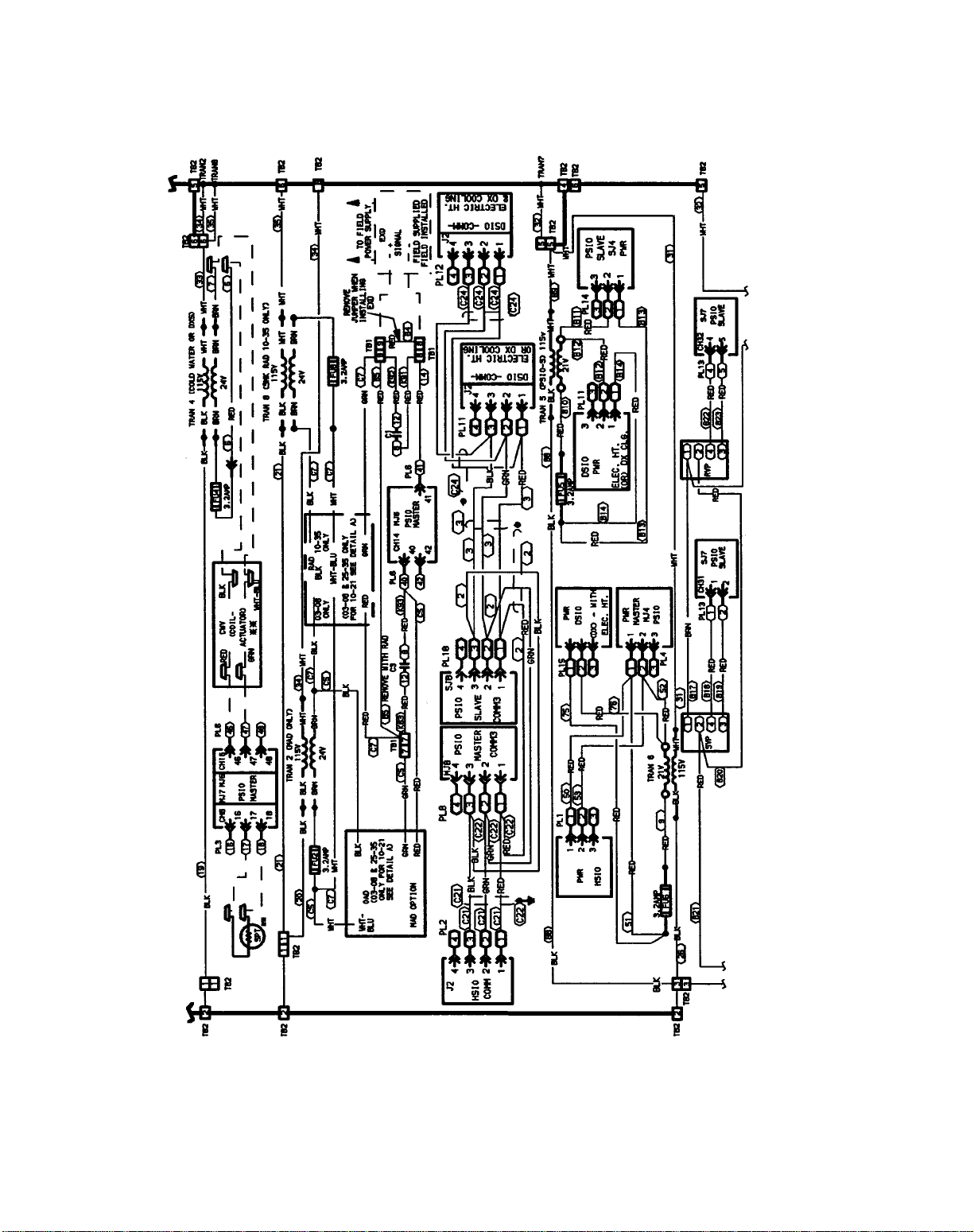
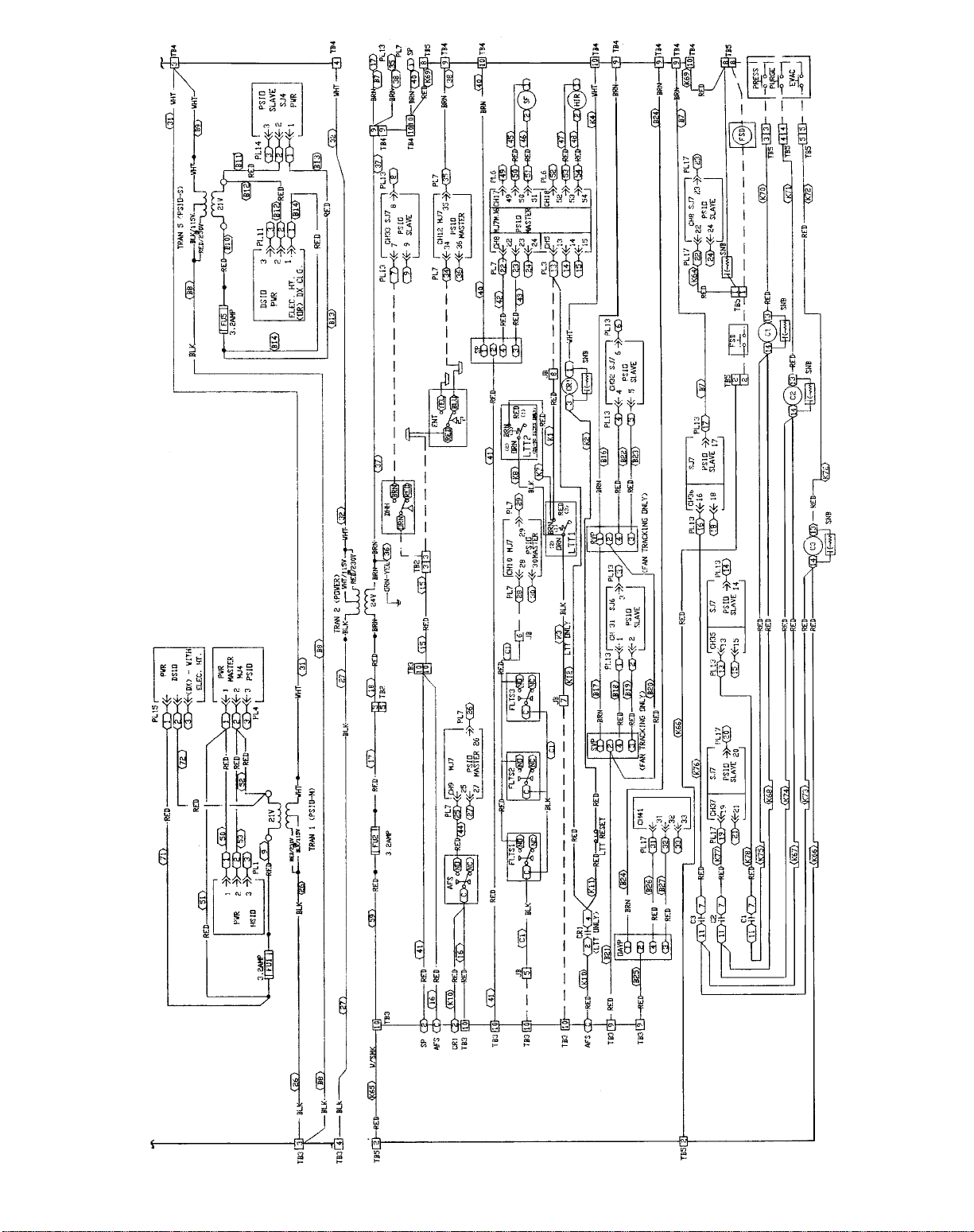
See Fig. 5-7 for control box component arrangements and
Fig. 8 for fan motor wiring. PIC input and output points are
listed in Table 1. Consult the wiring diagram located in the
control box or Fig. 9-12 for further details.
Power is present in the PIC control box in the motor
starter circuit even when the dedicated power to the PIC
control box is off.
The supply and return fan starter circuits are independent
from each other. Either circuit and its related control box
interface can have 24 vac, 120 vac, or 240 vac power.
All options that require a factory-installed transformer
are fused with 3.2 amp fuses on the secondary of each
transformer.
When the control box is shipped separately for remote mounting, all unit wiring terminates in a junction box located in
the fan section. Refer to Fig. 12 for the applicable wiring
diagram and Table 2 for junction box connections.
If the unit is provided with a factory-installed smoke control option, refer to the section titled Field-Wiring Connections, Smoke Control Option, page 54.
All PIC electrical components are UL (Underwriters’Laboratories) listed. The electronic modules are approved under
UL HVACEquipment Standard 873. PIC units are listed and
labeled by ETL (Engineering Testing Laboratory) to comply
with UL Standard 1995 for heating and cooling units, and
comply with NFPA (National Fire Protection Association)
Standard 90A.
3
Page 4

LEGEND
ABX — Air Blender
AF — Airfoil
CV — Constant Volume
IGV — Inlet Guide Vanes
FC — Forward-Curved
FMB — Filter Mixing Box
MXB — Mixing Box
PIC — Product Integrated Controls
VAV — Variable Air Volume
*The cv capacity rating is the flow (gpm) through a valve at 1 psi pres-
sure drop.
Fig. 1 — Basic PIC Order Number
4
Page 5

LEGEND
AF — Airfoil
CV — Constant Volume
DX — Direct Expansion
FC — Forward-Curved
FMB — Filter Mixing Box
MXB — Mixing Box
N.C. — Normally Closed
N.O. — Normally Open
PIC — Product Integrated Controls
VAV — Variable Air Volume
*The cv capacity rating is the flow (gpm) through a
valve at 1 psi pressure drop.
Fig. 2 — PIC Option Order Number
5
Page 6

NOTE: Dimensions in [ ] are in millimeters.
Fig. 3 — Control Box for Remote Mounting
Fig. 4 — Sealing Control Wiring in Flexible Conduit
6
Page 7

LEGEND (Fig. 5-12, Table 2)
AFS — Airflow Switch
AO — Analog Output
AOTC — Analog Output Temperature Control
AQ
AQ
C—Contactor
— Air Quality Sensor, No. 1
1
— Air Quality Sensor, No. 2
2
CCW — Counterclockwise
CH — Channel
CR — Control Relay
CUST — Condensing Unit Status
CV — Constant Volume
CW — Clockwise
CWV — Chilled Water Valve
DHH — Duct High Humidity
DO — Discrete Output
DOTC — Discrete Output Temperature Control
DSIO — Control Module, Electric Heat and/or DX
DTCC — Discrete Time Clock Control
DX — Direct Expansion
DXS — DX Cooling Stage
DXSD — Direct Expansion Cooling Shutdown
EHS — Electric Heaters
ELEC — Electric
ENT — Enthalpy Switch
EQUIP — Equipment
EVAC — Smoke Evacuation Input
EXD — Exhaust Air Damper Actuator
FLTS — Filter Status Switch
FSD — Fire Shutdown Device
FU — Fuse
GND — Ground
HIR — Heat Interlock Relay
HOA — Hand-Off-Auto. Switch
HPS — High-Pressure Switch
HSIO — Keyboard and Display Module
HT — Heat
HUM — Humidifier
HWV — Hot Water Valve
IGV — Inlet Guide Vane Actuator
LTT — Low Temperature Thermostat
MAD — Mixed-Air Damper Actuator
MAT — Mixed-Air Temperature
MPSIO — Master Processor Module
(Processor Module)
OAD — Outdoor-Air Damper Actuator
OARH — Outdoor-Air Relative Humidity
OAT — Outdoor-Air Temperature
OAVP — Outdoor-Air Velocity Pressure
OT — Outside-Air Thermostat
PH — Preheat
PL — Plug Assembly
PRESS — Smoke Pressurization Input
PSIO — Processor Module
PURG — Smoke Purge Input
RAD — Return-Air Damper Actuator
RAT — Return-Air Temperature
RFAN — Return Fan
RFR — Return Fan Relay
RFVC — Return Fan Volume Control
RH — Relative Humidity
RVP — Return Velocity Pressure
SAT — Supply-Air Temperature
SF — Fan Status Relay
SFAN — Supply Fan
SFR — Supply Fan Relay
SMK — Smoke
SNB — Snubber
SP — Static Pressure Transducer
SPSIO — Slave Processor Module
(Option Module)
SPT — Space Temperature
SVP — Supply Velocity Pressure
SW — Switch
TB — Terminal Block Terminal
TEMP — Temperature
TRAN — Transformer
VAV — Variable Air Volume
W/ — With
WO/ — Without
Marked Wire or Cable
Terminal (Marked)
Terminal (Unmarked)
Terminal Block
Splice (Factory)
Splice (Field)
Wiring Factory
Wiring Field Control
Wiring Field Power
Option or Accessory
Common Potential
NOTES:
1. Use copper conductors only.
2. Wire is in accordance with National Electrical Code (NEC).Forlocalcodes,
replace original wires with 90 C wire or its equivalent.
3. Replace wires fromIGV, FLTS,MAT,SAT,OAD,RAD,andELEC HTwith
125 C plenum cable conductor as required.
4. Input channel numbers and points for configuration of the optional
analog output temperature control (AOTC) follow:
CHANNEL SENSOR DESCRIPTION
1 SAT Supply-Air Temperature
2 OAT Outdoor-Air Temperature
3 MAT Mixed-Air Temperature
6 SPT Space-Air Temperature
7 RAT Return-Air Temperature
34 TEMP Preheat or Optional Carrier Sensor
5. Reference for wire markers, where ‘X’ represents a numeral:
X — Item number on wiring harness
BX — Box wire
CX — Cable
KX — Accessory kit wire
7
Page 8

ARRANGEMENT FOR SIZES 03 AND 06
ARRANGEMENT FOR SIZES 08 THROUGH 35
Fig. 5 — PIC Section Control Box Component Arrangements, 39L
8
Page 9

Fig. 6 — PIC Section Control Box Component Arrangement, 39NX Sizes 07-21
9
Page 10

Fig. 7 — PIC Section Control Box Component Arrangement, 39NX Sizes 26-92
10
Page 11

Fig. 8 — Fan Motor Starter Circuit and PIC Control Wiring Interface — PIC Power for
Control Circuit From Dedicated Source
11
Page 12

MODULE,
DEFAULT ADDRESS
PSIO (Processor)
ADDRESS 1
PSIO (Option)
ADDRESS 31
DSIO (Electric Heat)
ADDRESS 19
DSIO (DX without
Electric Heat)
ADDRESS 19
DSIO (DX with
Electric Heat)
ADDRESS 49
Table 1 — Input and Output Points
INPUT
SAT AI 1 IGV* AO 13
OAT AI 2 MIXD AO, DO† 14
MAT AI 3 HWC AO 15
RH AI 4 CWC AO 16
LTT DI 5 SF DO 17
SPT AI 6 HIR* DO 18
RAT AI 7 — — —
SP* AI 8 — — —
AFS DI 9 — — —
FLTS DI 10 — — —
OARH AI 11 — — —
ENT DI 12 — — —
SVP* AI 31 RFVC* AO 43
RVP* AI 32 HUM1 AO, DO 44
DHH DI 33 HUM2 DO 45
TEMP AI 34 AOTC AO 46
PRES DI 35 DOTC DO 47
EVAC DI 36 DTCC DO 48
PURG DI 37 — — —
FSD DI 38 — — —
AQ1 AI 39 — — —
AQ2 AI 40 — — —
OAVP* AI 41 — — —
METER DI 42 — — —
— — — EHS1 DO 23
— — — EHS2 DO 24
— — — EHS3 DO 25
— — — EHS4 DO 26
— — — EHS5 DO 27
— — — EHS6 DO 28
— — — EHS7 DO 29
— — — EHS8 DO 30
CUST DI 19 DXS1 DO 23
DXSD DI 20 DXS2 DO 24
— — — DXS3 DO 25
— — — DXS4 DO 26
— — — DXS5 DO 27
— — — DXS6 DO 28
— — — DXS7 DO 29
— — — DXS8 DO 30
CUST DI 49 DXS1 DO 53
DXSD DI 50 DXS2 DO 54
— — — DXS3 DO 55
— — — DXS4 DO 56
— — — DXS5 DO 57
— — — DXS6 DO 58
— — — DXS7 DO 59
— — — DXS8 DO 60
INPUT
TYPE
CHANNEL
NUMBER
OUTPUT
OUTPUT
TYPE
CHANNEL
NUMBER
AFS — Airflow Switch (Supply Fan
AI — Analog Input
AO — Analog Output
AOTC — Analog Output Temperature
AQ1, 2 — Air Quality Sensors 1, 2
CUST — Condensing Unit Status
CWC — Chilled Water Coil
DI — Discrete Input
DHH — Duct High Humidity
DO — Discrete Output
DOTC — Discrete Output Temperature
DTCC — Discrete Output Timeclock
*Available on VAV only.
†Discrete output with two-posi ion damper control.
Status Switch)
Control
(Outdoor Air Thermostat)
Control
Control
LEGEND
DXS1-8 — Direct Expansion Cooling
DXSD — Direct Expansion Cooling
EHS1-8 — Electric Heater Stages 1-8
ENT — Enthalpy Switch
EVAC — Evacua ion
FLTS — Filter Status Switch
FSD — Fire Shutdown
HIR — Heat Interlock Relay
HWC — Hot Water Coil
HUM1, 2 — Humidity Stages 1, 2
IGV — Inlet Guide Vanes
LTT — Low Temperature Thermostat
MAT — Mixed-Air Temperature
METER — Meter (Pulsed Dry-Contact
Stages 1-8
Shutdown
(also labelled FRZ)
Input)
12
MIXD — Mixed-Air Dampers
OARH — Outdoor-Air Relative Humidity
OAT — Outdoor-Air Temperature
OAVP — Outdoor-Air Velocity Pressure
PRES — Pressurization
PURG — Purge
RAT — Return-Air Temperature
RFVC — Return Fan Volume Control
RH — Relative Humidity
RVP — Return Velocity Pressure
SAT — Supply-Air Temperature
SF — Supply Fan Relay
SP — Static Pressure
SPT — Space Temperature
SVP — Supply Velocity Pressure
TEMP — Optional Temperature Input
Page 13

13
Fig. 9 — Unit Wiring Schematic, 39L Sizes 03-35 (115 v, Typical)
Page 14
14
Fig. 9 — Unit Wiring Schematic, 39L Sizes 03-35 (115 v, Typical) (cont)
Page 15

15
Fig. 9 — Unit Wiring Schematic, 39L Sizes 03-35 (115 v, Typical) (cont)
Page 16

Fig. 9 — Unit Wiring Schematic, 39L Sizes 03-35 (115 v, Typical) (cont)
16
Page 17

Fig. 9 — Unit Wiring Schematic, 39L Sizes 03-35 (115 v, Typical) (cont)
17
Page 18

Fig. 9 — Unit Wiring Schematic, 39L Sizes 03-35 (115 v, Typical) (cont)
18
Page 19

19
Fig. 10 — Unit Wiring Schematic, 39NX Sizes 07-21 (115 v, Typical)
Page 20

20
Fig. 10 — Unit Wiring Schematic, 39NX Sizes 07-21 (115 v, Typical) (cont)
Page 21

21
Fig. 10 — Unit Wiring Schematic, 39NX Sizes 07-21 (115 v, Typical) (cont)
Page 22

Fig. 10 — Unit Wiring Schematic, 39NX Sizes 07-21 (115 v, Typical) (cont)
22
Page 23

Fig. 10 — Unit Wiring Schematic, 39NX Sizes 07-21 (115 v, Typical) (cont)
23
Page 24

Fig. 10 — Unit Wiring Schematic, 39NX Sizes 07-21 (115 v, Typical) (cont)
24
Page 25

25
Fig. 11 — Unit Wiring Schematic, 39NX Sizes 26-92 (115 v, Typical)
Page 26

26
Fig. 11 — Unit Wiring Schematic, 39NX Sizes 26-92 (115 v, Typical) (cont)
Page 27

27
Fig. 11 — Unit Wiring Schematic, 39NX Sizes 26-92 (115 v, Typical) (cont)
Page 28
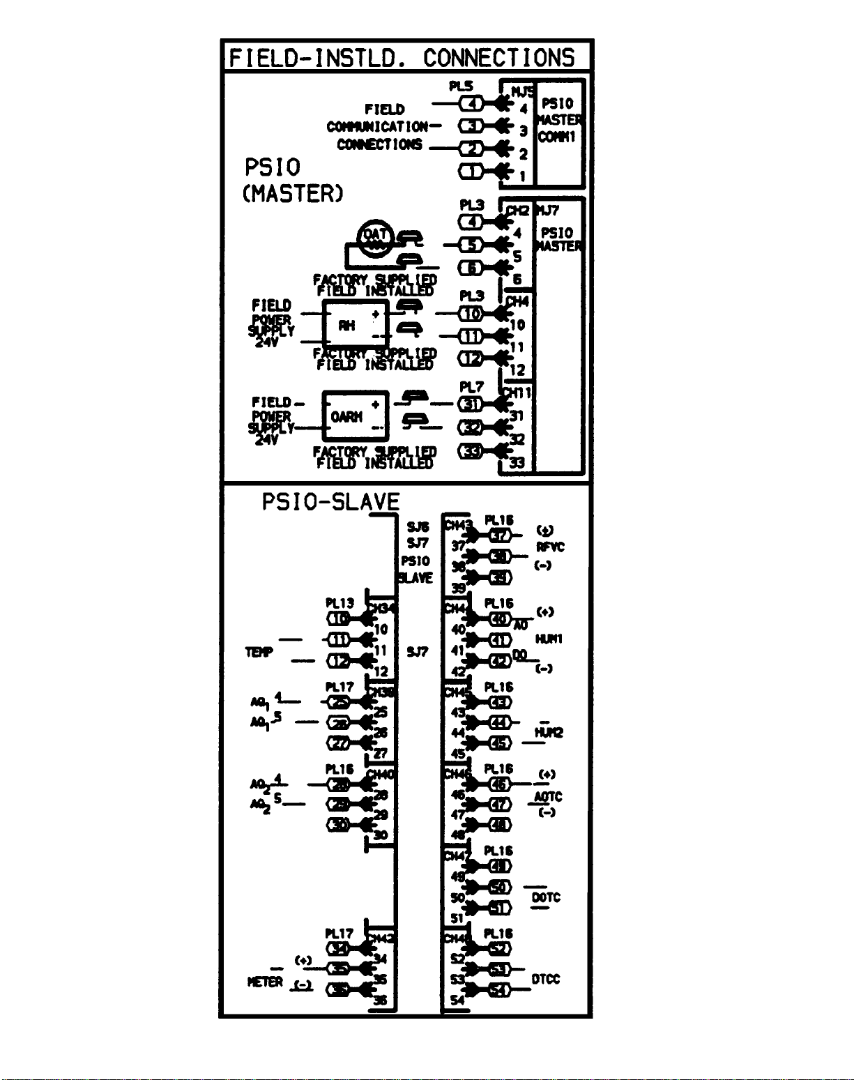
Fig. 11 — Unit Wiring Schematic, 39NX Sizes 26-92 (115 v, Typical) (cont)
28
Page 29

Fig. 11 — Unit Wiring Schematic, 39NX Sizes 26-92 (115 v, Typical) (cont)
29
Page 30

Fig. 11 — Unit Wiring Schematic, 39NX Sizes 26-92 (115 v, Typical) (cont)
30
Page 31

31
Fig. 12 — Unit Wiring Schematic, 39L and 39NX PIC with Remote Control Box
Page 32

32
Fig. 12 — Unit Wiring Schematic, 39L and 39NX PIC with Remote Control Box (cont)
Page 33
33
Fig. 12 — Unit Wiring Schematic, 39L and 39NX PIC with Remote Control Box (cont)
Page 34

Fig. 12 — Unit Wiring Schematic, 39L and 39NX PIC with Remote Control Box (cont)
34
Page 35
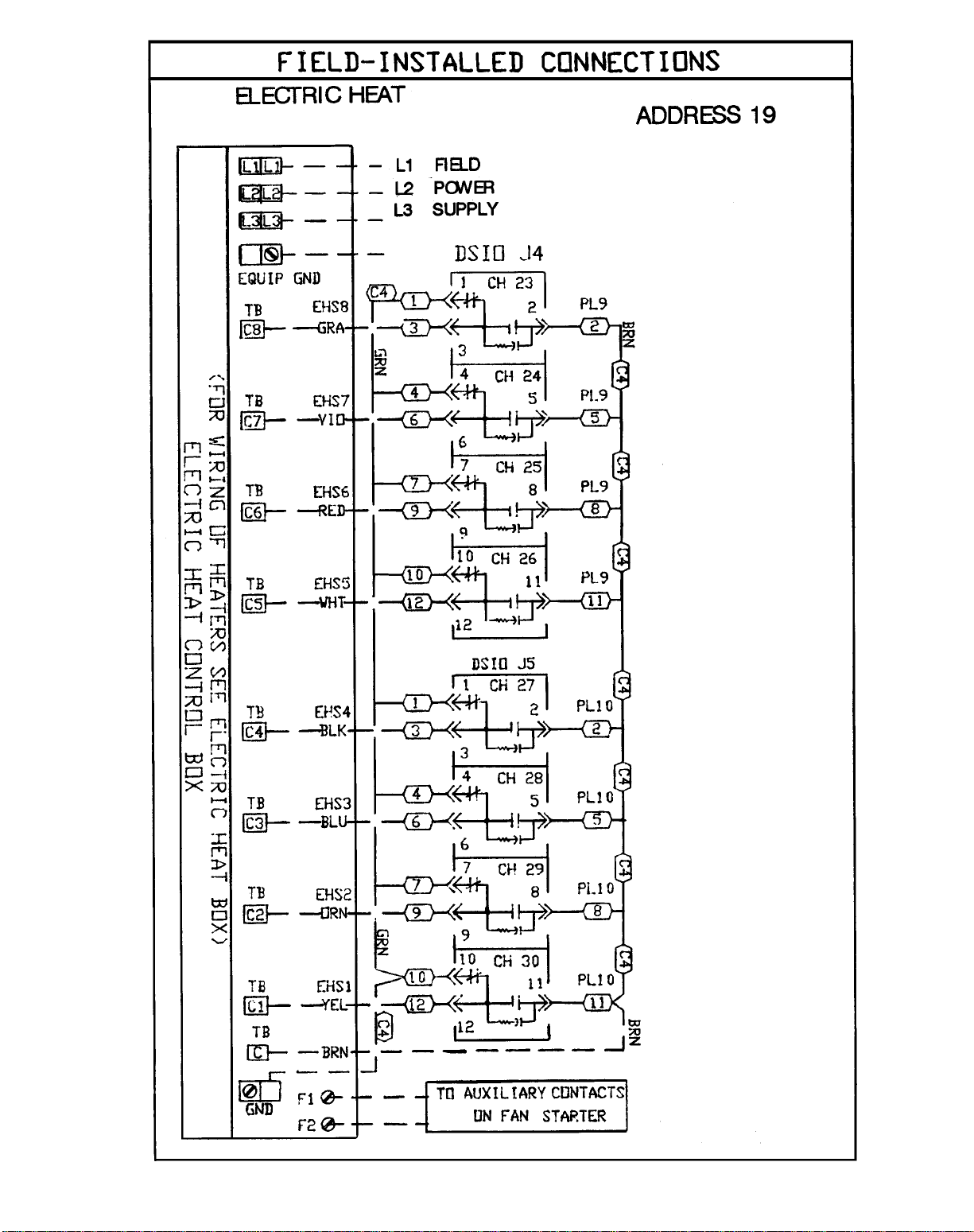
Fig. 12 — Unit Wiring Schematic, 39L and 39NX PIC with Remote Control Box (cont)
35
Page 36
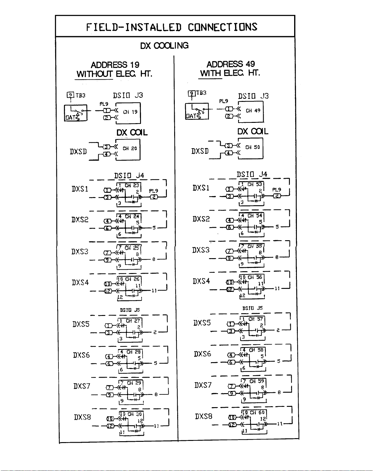
Fig. 12 — Unit Wiring Schematic, 39L and 39NX PIC with Remote Control Box (cont)
36
Page 37

Table 2 — Junction Box Connections for Optional Remote Control Box
REMOTE
CONTROL BOX
LOCATION
MPSIO 2 SAT — BLK 1
MPSIO 3 SAT — RED 2
MPSIO 8 MAT — BLK 3
MPSIO 9 MAT — RED 4
TB3 10 FLTS — BLK 5
MPSIO 28 FLTS — RED 6
TB3 10 LTT — K3 7
MPSIO 13 LTT — K1 8
TB2 19 OAD — BLK 9
TB2 20 OAD — WHT 10
TB2 6 OAD — GRN 11
MPSIO 40 OAD — RED 12
TB2 21 RAD — BLK 13
TB2 22 RAD — WHT 14
TB2 7 RAD — GRN 15
TB2 6 RAD — RED 16
TB2 27 EXD — BLK 17
TB2 28 EXD — WHT 18
TB2 8 EXD — GRN 19
TB2 7 EXD — RED 20
TB2 15 SFAN1 — BLK 21
TB2 16 SFAN1 — WHT 22
MPSIO 38 SFAN1 — GRN 23
MPSIO 37 SFAN1 — RED 24
TB2 17 SFAN2 — BLK 25
TB2 18 SFAN2 — WHT 26
TB2 23 RFAN1 — BLK 27
TB2 24 RFAN1 — WHT 28
SPSIO 38 RFAN1 — GRN 29
SPSIO 37 RFAN1 — RED 30
TB2 25 RFAN2 — BLK 31
TB2 26 RFAN2 — WHT 32
SPSIO 12 PH — BLK 33
SPSIO 11 PH — RED 34
NOTES:
1. Pneumatic tubing to connect the airflow sensor in the fan to the remote control box is bundled with the internal PIC wiring to the junction box,
but does not enter the box. Route tube directly to remote control box along with conduit containing wiring from junction box to remote control box.
2. See Legend on page 7.
CONTROL
BOX
TERMINAL
FAN SECTION
JUNCTION BOX
SIGNAL
JUNCTION
BOX
TERMINAL
37
Page 38

Variable-Frequency Drives — The input signal for
the inverter must be 4 to 20 mA. Use a 2-conductor
20 AWG (American Wire Gage) cable (single twisted pair,
unshielded) to connect the input of the inverter to the output
of the PIC control terminals. See Fig. 8.
Wire the inverter so that if it is placed in the manual or
bypass mode the low temperature thermostat and the highpressure switch (if supplied) are still in the motor control
circuit to protect the unit.
Adjust the minimum inverter speed to provide at least 10%
airflow when inlet guide vanes are at 0% (4 mA) and maximum design airflow when inlet guide vanes are at 100%
(20 mA). Use the local interface device to verify that the
supply fan status ( ) shows the fan is ON and that the
supply fan is operating at the lowest airflow adjustment. In-
crease inverter minimum speed as required. For additional
information, see the Quick Test section on page 103.
Water Valve Assemblies — Water valve assemblies
(Fig. 13) are shipped inside the fan section for field installation. All valve assemblies have electrically powered actuators. Each actuator has an external junction box for field
wiring.The junction box contains 24 vac power wires (WHITE/
BLUE, BLACK) and 4 to 20 mA signal wires (1RED,
−GREEN). The actuators operate the valve through a linear
stroke; if power is lost, a return spring reverses the stroke
and returns the valve stem to the normal position.
VAL VE ACTUATOR
ACTUATOR LINKAGE
VALVE BODY
To prevent electric shock and equipment damage, disconnect the power to the control box before installing
valve assemblies. Turn power switch located on control
box door to OFF.
On installations where valve mounting space is limited,
use unions to couple valve assemblies to water lines. If unions
do not provide sufficient clearance, refer to the Valve
Troubleshooting section, page 109.
On chilled water applications or hot water applications with
1
⁄2to 3-in. valves, the valve actuators can be mounted in
1
any position above the centerline of the valve body.For steam
applications or hot water applications with1⁄2to 11⁄4-in. valves
that have actuators and high-temperature linkage extensions, mount the actuator above the centerline of the valve
body and 45 degrees from vertical. This position helps to
prevent actuator exposure to direct heat convection.
DO NOT install valve assembly where excessive moisture, corrosive fumes, and/or vibration are present.
INSTALL all 2-way valve assemblies so that they close
against system flow. An arrow on the valve body indicates the proper flow direction.
ALWAYS install 3-way mixing valve with 2 inlet flows
and one outlet. Normal flow will be from port B to port
AB with stem up. See Fig. 14.
Fig. 13 — Valve Assembly (T ypical)
Fig. 14 — Three-Way Mixing Valve — Normal Flow,
T ypical Piping
38
Page 39
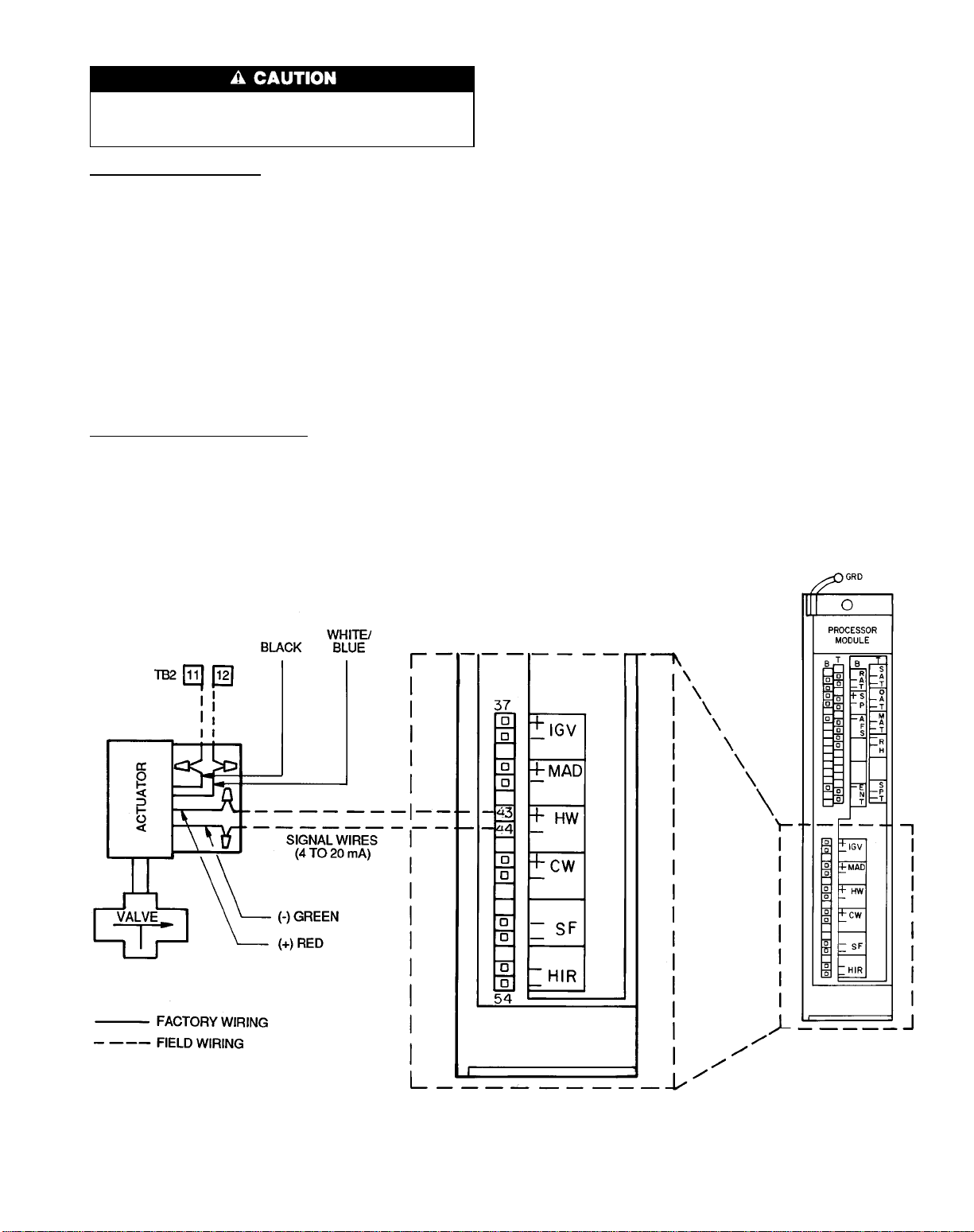
VALVE WIRING
Valves MUST be connected to the correct processor module terminal to operate properly. Damage to the actuator
may occur if the valve is improperly connected.
Hot WaterValves (Fig. 15) — Using a 4-conductor 20AWG
cable (two twisted pairs, no shield), connect the hot water
valve actuator as follows:
1. Using twist-on wire connectors, connect the BLACK and
WHITE/BLUE leads inside the actuator junction box to
the 24 vac power wires of the cable. Connect the other
ends of the power wires to TB2, pins 11 and 12, in the
PIC control box.
2. Using twist-on wire connectors, connect the RED ( ) and
GREEN (−) leads inside the actuator junction box to the
other 2 wires in the cable. Note the polarity of each wire.
3. Connect the positive signal wire (connected to the RED
lead) to pin 43 on the processor module. Connect the negative signal wire (connected to the GREEN lead) to pin 44
on the processor module.
Chilled Water Valves (Fig. 16) — Using a 4-conductor
20 AWG cable (two twisted pairs, no shield), connect the
chilled water valve actuator as follows:
1. Using twist-on wire connectors, connect the BLACK and
WHITE/BLUE leads inside the actuator junction box to
the 24 vac power wires of the cable. Connect the other
ends of the power wires to TB2, pins 9 and 10, in the PIC
control box.
2. Using twist-on wire connectors, connect the RED ( ) and
GREEN (−) leads inside the actuator junction box to the
other 2 wires in the cable. Note the polarity of each wire.
3. Connect the positive signal wire (connected to the RED
lead) to pin 46 on the processor module. Connect the negative signal wire (connected to the GREEN lead) to pin 47
on the processor module.
Duct Static Pressure Probe (VAV Units) — The
duct static pressure probe is shipped inside the control box.
Select a location in the ductwork where the static pressure
will be representative of the static pressure to be monitored
and maintained (typically 2/3 of the distance down the duct
from the fan). Install the probe with the tip facing the airflow. See Fig. 17.
Use
1
⁄4-in. OD approved polyethylene tubing for up to
50 ft (3⁄8-in. OD for 50 to 100 ft) to connect the probe to the
39L or 39NX unit. Route the tubing back to the mechanical
room and connect the tubing to the bulkhead fitting labelled
H (HIGH), located on the bottom edge of the 39L control
box or top edge of the 39NX control box.
NOTE: If the probe is more than 100 ft from the control
box, it is recommended that the static pressure sensor be removed from the control box and mounted remotely.The sensor should be mounted closer to the probe and then rewired
to the original connections in the control box.
NOTE: Connections for 39NX with integral PIC shown. See wiring
diagrams in Fig. 9 and 12 for terminal connections in 39L control box
and all remote-mount control boxes.
Fig. 15 — Hot Water Valve Wiring
39
Page 40

FACTORY WIRING
FIELD WIRING
NOTE: Connections for 39NX with integral PIC shown. See wiring
diagrams in Fig. 9 and 12 for terminal connections in 39L control box
and all remote-mount control boxes.
Fig. 16 — Chilled Water Valve Wiring
Space TemperatureSensor (Fig. 18) — The space
temperature sensor (SPT) is packaged and shipped inside the
fan section. It is installed on a building interior wall to measure room air temperature.
The wall plate accommodates both the NEMA (National
Electrical Manufacturers’ Association) standard and the
European
use of a junction box to accommodate the wiring is recommended for installation. The sensor can be mounted directly
on the wall, if acceptable by local codes.
DO NOT mount the sensor in drafty areas such as near
heating or air conditioning ducts, open windows, fans,
or over heat sources such as baseboard heaters or radiators.
Sensors mounted in these areas produce inaccurate readings.
1
⁄4DIN (Deutsche Industrie Norm) standard. The
Fig. 17 — Duct Static Pressure Probe
Avoid corner locations. Allow at least 3 ft between the
sensor and any corner. Airflow near corners tends to be reduced, resulting in erratic sensor readings.
The sensor should be mounted approximately 5 ft up from
the floor, in the area representing the average temperature.
Install the sensor as follows:
1. Remove sensor cover. Using a small blade screwdriver,
insert blade into sensor cover latch slot on bottom of slat.
Gently push upward on the screwdriver to release the cover
latch. Rotate the cover forward as the screwdriver is removed.
2. Snap off the wall plate from the base assembly.
3. Feed the wires from the electrical box through the sensor
base assembly.
5
4. Using two 6-32 x
⁄8-in. flat screws, mount the sensor base
assembly to the electrical box.
5. Dress the wires down and inside the perimeter of the sen-
sor base.
6. Attach the wall plate by snapping it onto the sensor base
assembly.
7. Replace the cover by inserting the top inside edge of the
cover over the tab on top of the sensor base assembly and
rotating the cover down. Snap cover on.
Refer to Field Wiring Connections section, page 52 for
wiring instructions and details. See Table 3 for Thermistor
Resistance vs. Temperature Values.
NOTE: Clean sensor with damp cloth only. Do not use
solvents.
40
Page 41
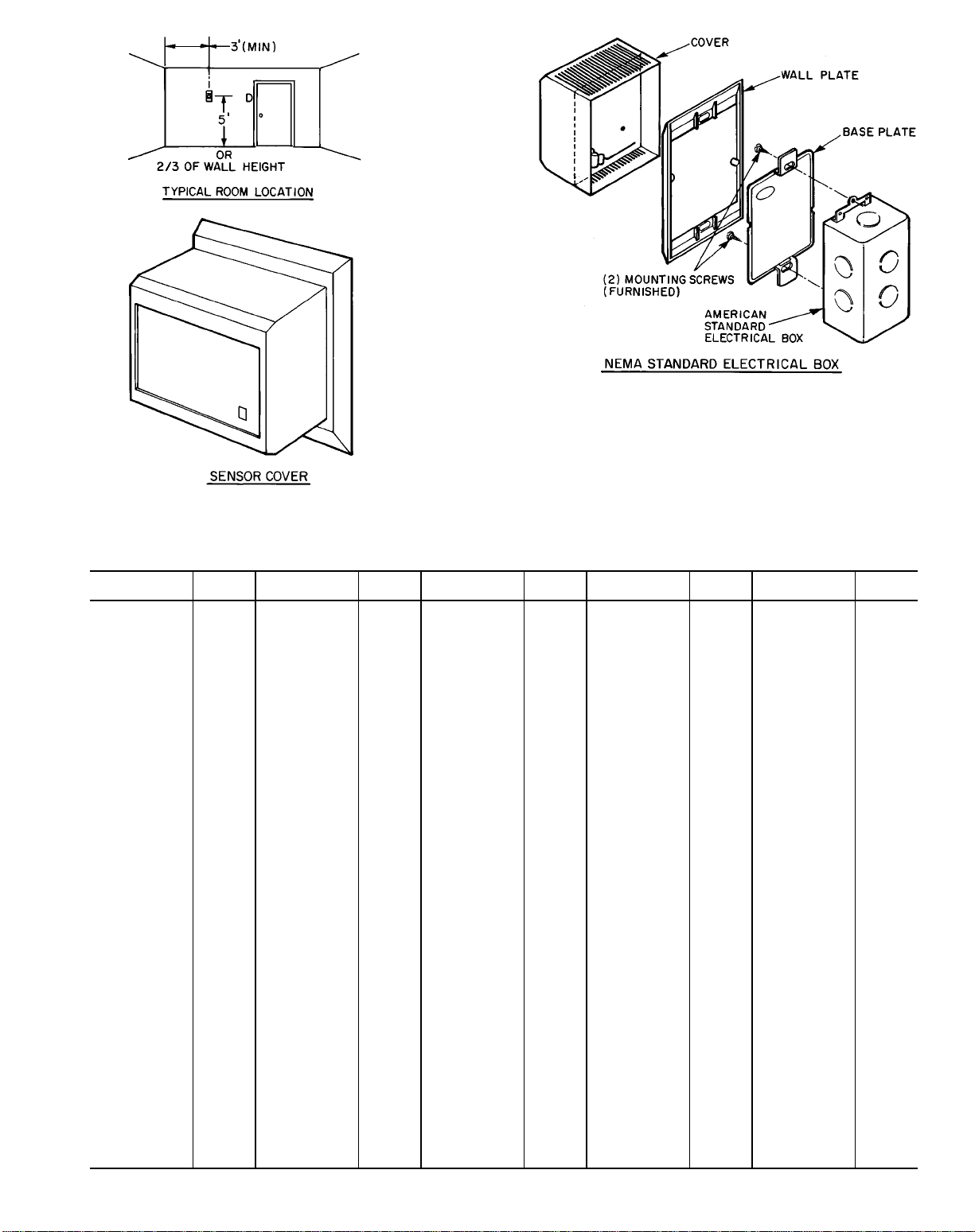
NEMA — National Electrical Manufacturers’ Association
Fig. 18 — Space Temperature Sensor (P/N HH51BX001)
Table 3 — Thermistor Resistance vs. Temperature Values for Space Temperature Sensor, Return-Air
Temperature Sensor, and Supply-Air Temperature Sensor
RESISTANCE
(Ohms)
173,631.0 −30 38,308.7 22 10,698.1 74 3602.5 126 1409.7 178
168,222.0 −29 37,304.0 23 10,459.4 75 3533.4 127 1386.3 179
162,998.0 −28 36,328.8 24 10,226.8 76 3465.9 128 1363.3 180
157,954.0 −27 35,382.1 25 10,000.0 77 3399.8 129 1340.7 181
153,083.0 −26 34,463.0 26 9,778.9 78 3335.2 130 1318.6 182
148,378.0 −25 33,570.7 27 9,563.4 79 3272.0 131 1296.9 183
143,833.0 −24 32,704.2 28 9,353.1 80 3210.1 132 1275.6 184
139,442.0 −23 31,862.8 29 9,148.2 81 3149.6 133 1254.8 185
135,200.0 −22 31,045.7 30 8,948.4 82 3090.4 134 1234.3 186
131,101.0 −21 30,252.0 31 8,753.5 83 3032.5 135 1214.2 187
127,139.0 −20 29,481.1 32 8,563.4 84 2975.8 136 1194.5 188
123,310.0 −19 28,732.2 33 8,378.0 85 2920.3 137 1175.1 189
119,609.0 −18 28,004.6 34 8,197.1 86 2866.0 138 1156.1 190
116,031.0 −17 27,297.7 35 8,020.7 87 2812.9 139 1137.5 191
112,571.0 −16 26,610.8 36 7,848.6 88 2760.9 140 1119.2 192
109,226.0 −15 25,943.4 37 7,680.6 89 2710.0 141 1101.3 193
105,992.0 −14 25,294.7 38 7,516.8 90 2660.2 142 1083.7 194
108,863.0 −13 24,664.2 39 7,356.9 91 2611.4 143 1066.4 195
99,837.3 −12 24,051.4 40 7,200.9 92 2563.7 144 1049.4 196
96,910.2 −11 23,455.6 41 7,048.6 93 2516.9 145 1032.8 197
94,078.4 −10 22,876.5 42 6,900.0 94 2471.2 146 1016.5 198
91,338.6 −9 22,313.4 43 6,755.0 95 2426.4 147 1000.4 199
88,687.3 −8 21,765.9 44 6,613.4 96 2382.5 148 984.7 200
86,121.6 −7 21,233.5 45 6,475.2 97 2339.5 149 969.2 201
83,638.4 −6 20,715.7 46 6,340.3 98 2297.5 150 954.0 202
81,234.8 −5 20,212.2 47 6,208.5 99 2256.3 151 939.1 203
78,908.0 −4 19,722.4 48 6,079.9 100 2215.9 152 924.5 204
76,655.3 −3 19,245.9 49 5,954.3 101 2176.4 153 910.1 205
74,474.2 −2 18,782.4 50 5,831.7 102 2137.7 154 896.0 206
72,362.1 −1 18,331.5 51 5,712.0 103 2099.8 155 882.2 207
70,316.7 0 17,892.8 52 5,595.0 104 2062.6 156 868.6 208
68,335.6 1 17,465.9 53 5,480.8 105 2026.3 157 855.2 209
66,416.7 2 17,050.4 54 5,369.2 106 1990.6 158 842.1 210
64,557.9 3 16,646.1 55 5,260.2 107 1955.7 159 829.2 211
62,756.9 4 16,252.6 56 5,153.7 108 1921.5 160 816.6 212
61,012.0 5 15,869.6 57 5,049.7 109 1887.9 161 804.1 213
59,321.1 6 15,496.8 58 4,948.1 110 1855.1 162 791.9 214
57,682.4 7 15,133.8 59 4,848.8 111 1822.9 163 779.9 215
56,094.3 8 14,780.4 60 4,751.8 112 1791.3 164 768.2 216
54,554.9 9 14,436.4 61 4,657.0 113 1760.4 165 756.6 217
53,062.2 10 14,101.3 62 4,564.4 114 1730.1 166 745.2 218
51,615.9 11 13,775.1 63 4,473.8 115 1700.4 167 734.0 219
50,213.1 12 13,457.3 64 4,385.3 116 1671.3 168 723.1 220
48,853.0 13 13,147.9 65 4,298.9 117 1642.7 169 712.3 221
47,533.9 14 12,846.4 66 4,214.3 118 1614.7 170 701.7 222
46,254.7 15 12,552.8 67 4,131.7 119 1587.3 171 691.3 223
45,013.9 16 12,266.8 68 4,050.9 120 1560.4 172 681.0 224
43,810.3 17 11,988.1 69 3,971.9 121 1534.1 173 671.0 225
42,642.6 18 11,716.6 70 3,894.6 122 1508.2 174 661.1 226
41,509.8 19 11,452.0 71 3,819.1 123 1482.9 175 651.4 227
40,410.5 20 11,194.2 72 3,745.3 124 1458.0 176 641.8 228
39,343.9 21 10,943.0 73 3,673.1 125 1433.6 177 632.4 229
TEMP
(F)
RESISTANCE
(Ohms)
TEMP
(F)
RESISTANCE
(Ohms)
TEMP
(F)
RESISTANCE
(Ohms)
TEMP
(F)
RESISTANCE
(Ohms)
TEMP
(F)
41
Page 42
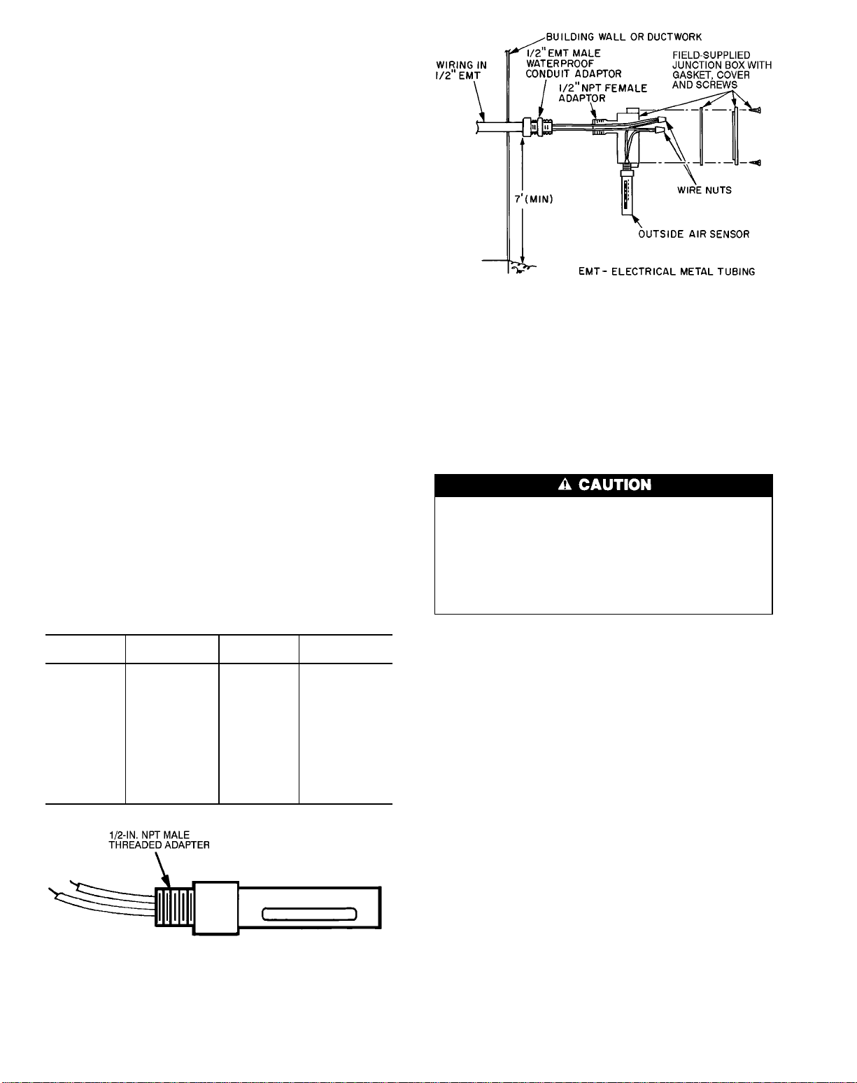
Outdoor-Air Temperature Sensor (Fig. 19) —
The outdoor-air temperature (OAT) sensor is shipped inside
the fan section. The OAT sensor continuously monitors the
temperature of the air outside the building. The integral shield
prevents ice formation on the sensor conductors. A fieldsupplied conduit junction box is required for installation. See
Fig. 20.
Position the OAT sensor so that it accurately senses only
the outdoor-air temperature. The sensor must be located upstream from outside air dampers and located where it is unaffected by interior and duct temperatures. During the unoccupied (fan off) period the sensor’s location should have a
minimal effect on its readings.
Do not mount the sensor in direct sunlight. Inaccurate readings may result. It may be necessary to field-fabricate a shield
to protect the sensor from direct sunlight.
Do not mount the sensor near the exhaust from airhandling units or compressors, or near leakage drafts of indoor air, or near shrubbery or trees. Inaccurate readings may
result. Do not mount under direct water runoff. Water may
freeze around the sensor in winter and produce a false
reading.
If sensor wire is shielded, strip back the sensor shield and
tape it to prevent contact.
Position the sensor with the slotted end pointed
downward.
The field-supplied junction box housing must be threaded
to screw onto a male
conduit adaptor.The assembledbox and sensor mustbe mounted
parallel to the building wall. See Fig. 20. The sensor can
also be installed on a roof or other location.
For distances up to 500 ft, use 2-conductor 20 AWGcable
to connect the sensor to the PIC terminals. Refer to the Field
Wiring Connections section, page 52 for further wiring instructions. See Table4 for thermistor resistance according to
temperature value.
Table 4 — Thermistor Resistance vs
Temperature Values for Outdoor-Air
RESISTANCE
(Ohms)
168,250 −40 5,000.0 77
121,350 −31 4,028.5 86
88,500 −22 3,265.0 95
65,200 −13 2,663.3 104
48,535 −4 2,185.0 113
36,476 5 1,801.5 122
27,665 14 1,493.0 131
21,165 23 1,244.0 140
16,325 32 1,041.5 149
12,695 41 876.0 158
9,950 50 739.5 167
6,245 68 627.5 176
1
⁄2-in. NPT electrical metal tubing (EMT)
Temperature Sensor
TEMPERATURE
(F)
RESISTANCE
(Ohms)
TEMPERATURE
(F)
Fig. 20 — Outdoor-Air Temperature
Sensor Installation
Mixed-Air Temperature Sensor — The optional
mixed-air temperature sensor (MAT) is factory wired and
installed on all units with a factory-installed mixing box (MXB),
filter mixing box (FMB), or air blender (AMX). On units
without an AMX, MXB, or FMB, the optional MAT is packaged and shipped inside the fan section for field installation.
The field-installed MAT should be mounted downstream
of the return air duct and filters, but as close as possible to
the 39L or 39NX unit.
AVOID repeated bending of copper tubing, as this will
place stress on the sensor element and lead to eventual
breakage.
DO NOT fold or crimp copper tubing.
USE CARE in forming and securing the element.
STRIP back and tape the shield in order to prevent
contact.
Mount field-installed MAT as follows (Fig. 21):
1. Punch a 1-in. diameter hole in the duct and feed the sen-
sor element through the hole. Mount the utility box on
the outside of the duct.
2. Bend the copper tubing surrounding the sensor element
to conform to the area of the duct. Do not bend it to less
1
than 2
⁄2in. diameter on any turn. The sensor element
should be evenly distributed over the entire cross sectional area of the duct.
Existing support structures may be used for the sensor
element, as long as there is no metal-to-metal contact with
the copper tubing, and the mounting does not interfere
with other functions.
3. Use a field-supplied plastic spacer, clamp, and screws to
secure the sensor in the airstream. See Detail A,
Fig. 21.
4. Using 2-conductor 20 AWG plenum-rated cable, connect
the sensor to the PIC control box terminals.
Fig. 19 — Outdoor-Air Temperature Sensor
(P/N HH79NZ023)
42
Page 43

NOTE:This sensor uses a resistance temperature device (RTD)
element. Polarity is not a consideration.
When space does not allow working inside the duct, mount
as follows (Fig. 22):
1. Open a duct penetration on the opposite side of the sensor junction box.
3
2. Wrap the element around a
⁄4-in. PVC pipe, cut holes
near the center of the duct on both sides and feed the pipe
with sensor element through the hole.
3. Secure the seal around the PVC pipe.
NOTE: If local codes do not permit the use of PVC, use
EMT instead.
Refer to Field Wiring Connections section, page 52 for
wiring instructions and details. See Table 5 for RTD resistance vs temperature values.
Table 5 — RTD Resistance vs Temperature Values
for Mixed-Air Temperature Sensor
RESISTANCE
(Ohms)
693 −40 940 50 1223 140
719 −30 970 60 1257 150
745 −20 1000 70 1290 160
772 −10 1031 80 1325 170
799 0 1062 90 1360 180
827 10 1093 100 1395 190
854 20 1125 110 1430 200
883 30 1157 120 — —
912 40 1190 130 — —
TEMP
(F)
RESISTANCE
(Ohms)
TEMP
(F)
RESISTANCE
(Ohms)
TEMP
(F)
Enthalpy Switch (Fig. 23) — The enthalpy switch and
mounting template are located in a box shipped inside the
fan section.
The enthalpy switch is normally mounted in a horizontal
position with the sensing element exposed to freely circulating outdoor air.
DO NOT install enthalpy switch in locations where excessive moisture, corrosive fumes, and/or vibration are
present.
Fig. 22 — Alternate Mixed-Air Temperature
Sensor Installation
Mount the switch as follows:
1. Position mounting template on duct. Remove adhesive
backing and press template onto outside air duct.
2. Drill four
1
⁄8-in. mounting holes as indicated on the
template.
3. Cut out center portion of duct as outlined on template.
4. Mount controller to duct using screws provided.
If no outside air duct is present, mount the enthalpy switch
on a field-supplied and installed plate upstream of the outside air damper.
Connect the red and blue wires of the enthalpy switch to
the PIC control box terminals. Refer to Field Wiring
Connections section, page 52 for further details.
CONTROLRANGES — See Fig. 24 for control settings and
intermediate settings.
Fig. 21 — Mixed-Air Temperature Sensor
(P/N HH79NZ021) Installation
43
MOUNTING HOLES
Y
E
L
R
E
D
B
L
U
A
Fig. 23 — Enthalpy Switch (P/N HH57AC076)
D
C
B
Page 44

DIAL
SETTING
A
B
C
D
CONTROL SETTINGS
RELATIVE
HUMIDITY (%)
20 50 80
78 F
(26 C)
73 F
(23 C)
68 F
(20 C)
62 F
(17 C)
73 F
(23 C)
68 F
(20 C)
63 F
(17 C)
58 F
(14 C)
68 F
(20 C)
63 F
(17 C)
59 F
(15 C)
53 F
(12 C)
4. Remove the adhesive backing from the gasket; attach the
gasket to the outside of the junction box, aligning the holes
in the gasket with the holes in the box.
5. Attach the junction box to the duct with the 2 screws
provided.
6. Insert the probe assembly through the compression fitting and into the duct. Tighten screws one half-turn past
finger tight. Do not overtighten.
For distances up to 500 ft, use 2-conductor 20 AWGcable
to connect the sensor to the PIC control box terminals. Refer
to Field Wiring Connections section, page 32 for further details. See Table 3 for thermistor resistance vs. temperature
values.
CONTROL
CURVE
A
B
C
D
Fig. 24 — Enthalpy Control Settings
Supply-Air TemperatureSensor (Fig. 25) — The
supply-air temperature sensor (SAT) measures the temperature of the air as it leaves the supply fan. The sensor is factoryinstalled on the fan scroll.
Return-Air Temperature Sensor (Fig. 25) — The
return-air temperature sensor (RAT)is shipped inside the fan
section. It measures the temperature in the return air duct.
Mount the sensor in the middle of the return air duct approximately 4 to 5 ft from the return air damper. The sensor’s probe tip must be within a straight length of duct.
Mount the sensor as follows:
1. Remove the cover of the sensor junction box.
5
2. Drill or punch a
turn air duct as indicated in Fig. 26.
3. Drill or punch 2 holes through the sensor gasket into the
fan scroll.
⁄16-in. hole on the centerline of the re-
Fig. 25 — Supply/Return Air Temperature Sensor
(P/N HH79NZ019)
Fig. 26 — Return-Air Temperature Sensor
Installation
44
Page 45
Heat Interlock Relay (Fig. 27) — The heat interlock
relay (HIR) is factory wired and installed on VAV units only.
It is a single-pole, double-throw (SPDT) relay that provides
normally-open and normally-closed contacts to interface with
air terminal units. It allows the air terminals to open when
the PIC unit goes into the heating mode. The contacts are
silver cadmium oxide and are rated as follows:
48 va at 24 vac and .25 power factor
125 va at 115 vac and .25 power factor
125 va at 230 vac and .25 power factor
The contact terminations are no. 6 screw terminals.
NOTE: The HIR is not used in digital air volume control
(DAV) applications.
SDA 2 02 0
NC
2
COI L
DO NOT install the duct high humidity switch in locations where excessive moisture, corrosive fumes, and/or
vibration are present. Be sure to allow minimum dimensions from the elbows or junctions as indicated in
Fig. 29.
Mount the DHH as follows:
1. Position the mounting template on the duct. Remove adhesive backing and press template onto duct.
2. Drill four
template.
3. Cut out center portion of duct as outlined on template.
4. Mount DHH to duct using screws provided.
For distances up to 500 ft, use 2-conductor 20 AWG
cable to connect the switch to the PIC control box terminals.
Refer to Field Wiring Connections section, page 52 for further details.
The DHH adjustment knob provides settings from 15
to 95% relative humidity, The scale range is marked on the
face of the switch. The high humidity set point should be at
least 65%.
NOTE: The duct high humidity switch has a relative humidity differential of 5%.
1
⁄8-in. mounting holes as indicated on the
1
COM
Fig. 27 — Relay (P/N HK35AB001)
NO
Fan Relay — Thefan relay is factory wired and installed
on all 39L and 39NX units. It is a SPST relay that provides
a normally-open contact. The relay interfaces with the motor starter circuit and automatically starts/stops the fan when
the HOA switch is in the AUTO mode. The contacts are silver cadmium oxide and are rated as follows:
48 va at 24 vac and .25 power factor
125 va at 115 vac and .25 power factor
125 va at 230 vac and .25 power factor
The contact terminations are factory wired to TB1.
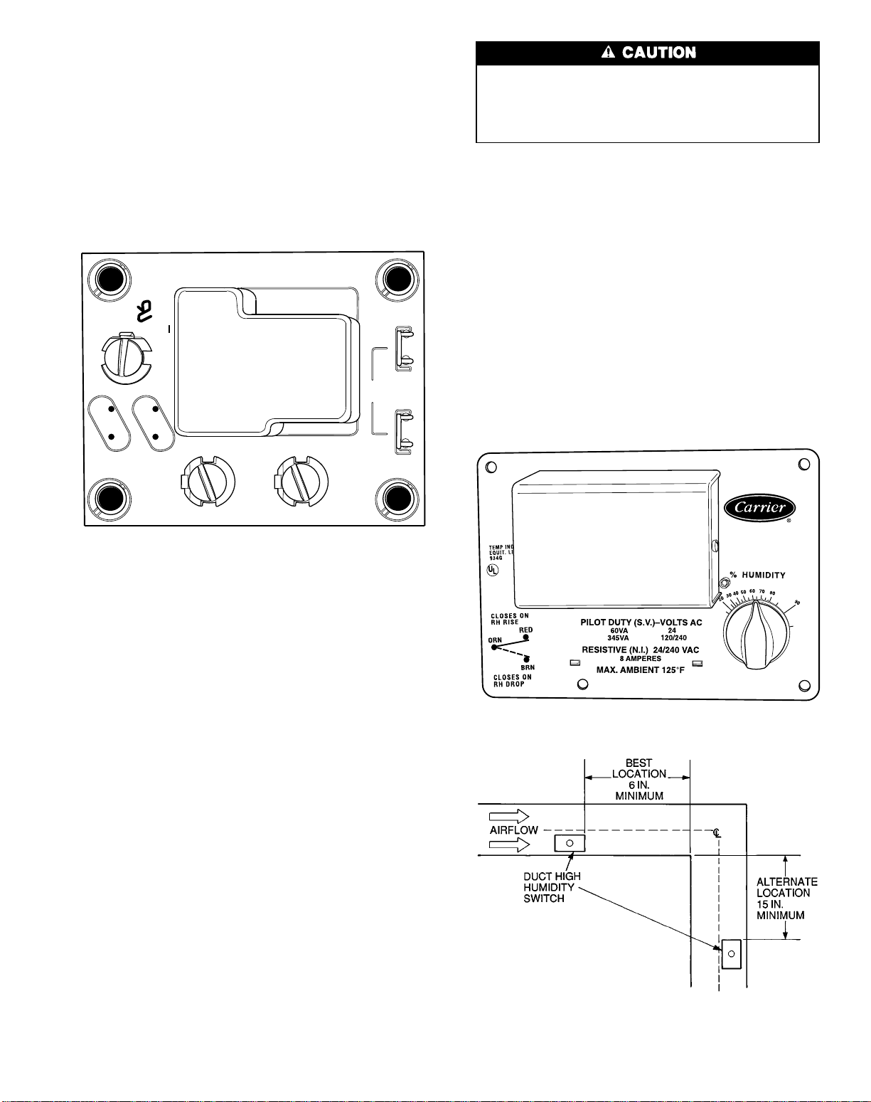
Duct High Humidity Switch (Fig. 28) — The duct
high humidity switch (DHH) is shipped inside the fan section. It is used as a safety input when the humidity control
options have been ordered. The DHH adjustment knob provides settings from 15 to 95% humidity.
Locate the DHH control element in the duct, downstream
of the humidifier. Adjust the DHH to the ASHRAE
(American Society of Heating, Refrigeration, and Air Conditioning Engineers) recommended maximum setting of 80%.
Settings higher than 80% are not recommended.
The DHH is normally mounted in a horizontal position on
the outside surface of the duct with the sensing element exposed to freely circulating air.
Fig. 28 — Duct High Humidity Switch
(P/N HL38ZG024)
45
Fig. 29 — Duct High Humidity Switch
Locations
Page 46
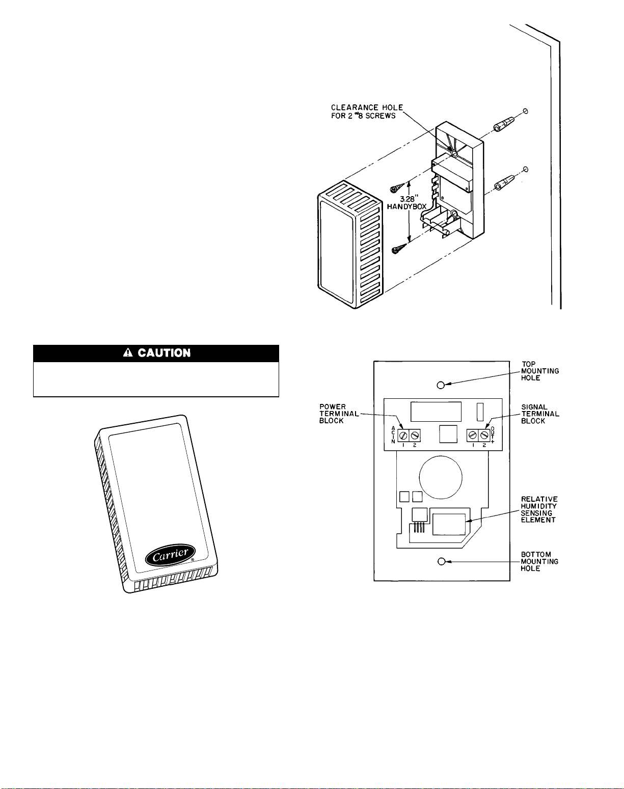
Wall-MountedRelative Humidity Sensor (Fig.30)
—
The wall-mounted relative humidity sensor is packaged
and shipped inside the fan section. It is installed on interior
walls to measure the relative humidity of the air within the
occupied space.
The use of a junction box to accommodate the wiring is
recommended for installation. The sensor may be mounted
directly on the wall, if acceptable by local codes.
DO NOT mount the sensor in drafty areas such as near
heating or air conditioning ducts, open windows, fans, or over
heat sources such as baseboard heaters or radiators. Sensors
mounted in those areas will produce inaccurate readings.
Avoid corner locations. Allow at least 3 ft between the
sensor and any corner. Airflow near corners tends to be reduced, resulting in erratic sensor readings.
Sensor should be vertically mounted approximately 5 ft
up from the floor, beside the space temperature sensor.
Install the sensor using 2 screws and 2 hollow wall anchors (if required); do not overtighten screws. See Fig. 31.
Sensor must be mounted with terminals ACIN and OUT
located at the top of the sensor as shown in Fig. 32.
For distances up to 500 ft, use 4-conductor 20 AWG
cable (2 twisted pairs, no shield) to connect the sensor to the
PIC control box terminals and power supply. Refer to Field
Wiring Connections section, page 52 for wiring instructions
and details.
The PIC controller has a space relative humidity default
set point of 40%.
Never attempt to clean or touch the sensing element with
chemical solvents, as permanent damage to the sensor
will occur.
Fig. 30 — Wall-Mounted Relative Humidity Sensor
(P/N HL39ZZ001)
Fig. 31 — Wall-Mounted Relative Humidity
Sensor Installation
Fig. 32 — Wall-Mounted Relative Humidity
Sensor Positioning
46
Page 47
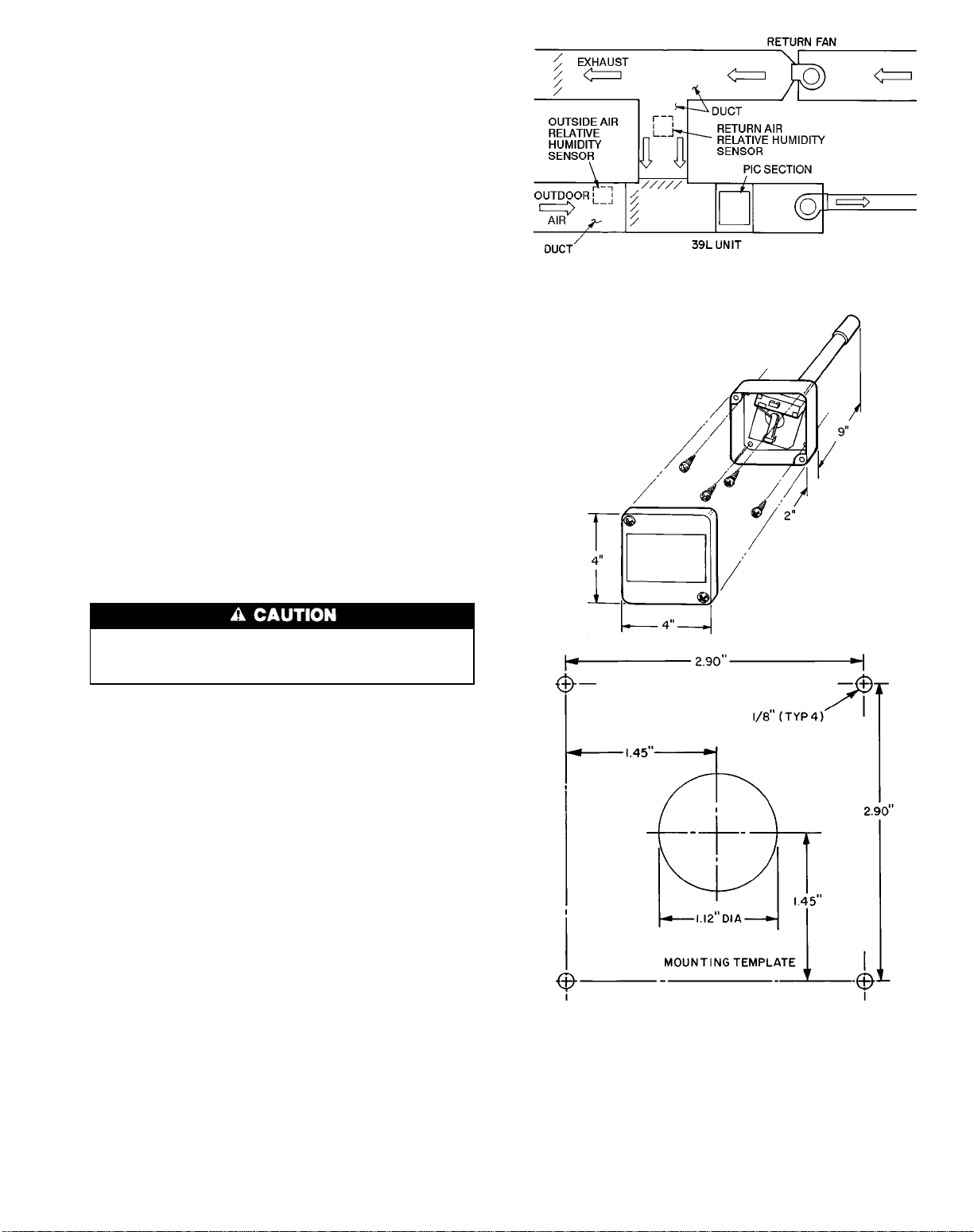
Duct-Mounted Relative Humidity Sensor — The
duct-mounted relative humidity sensor and mounting template are packaged and shipped inside the fan section. The
sensor is installed in either the return air ductwork or in the
outside air ductwork. If 2 relative humidity sensors are ordered for differential enthalpy control, then the sensors must
be installed in both the return air and outside air ducts. If the
sensor is used for control of a humidifier, install the sensor
in the return air duct.
The PIC controller has a return air relative humidity de-
fault set point of 40%.
LOCATION FOR OUTSIDE AIR RELATIVE HUMIDITY
— Locate the sensor where it accurately measures outdoor
conditions, yet is protected from the elements. During the
unoccupied (fan off)period, the sensor’slocation should have
a minimal effect on its readings.
LOCATION FOR RETURN AIR RELATIVE HUMIDITY
— Locate the sensor at least 6 in. upstream or 15 in. downstream of a 90 degree turn in the ductwork. The best location is 15 in. downstream of the 90 degree turn of the duct.
The probe should be mounted in the center of the duct. See
Fig. 33.
Mount the relative humidity sensor (Fig. 34) as follows.
1. Position mounting template on duct.
1
2. Drill four
template.
3. Punch a 1
template.
4. Mount sensor to duct using four no. 8 screws. Install 9-in.
sensor probe into the 1
⁄8-in. mounting holes as indicated on the
1
⁄8-in. hole as indicated on the mounting
1
⁄8-in. hole.
Fig. 33 — Duct-Mounted Relative Humidity
Sensor Locations
Never attempt to clean or touch the sensing element with
chemical solvents, as permanent damage to the sensor
will occur.
MixingBox Linkage — On units with mixing box (MXB)
or filter mixing box (FMB), the actuator and linkage are factory installed. The actuator is directly linked to the outdoorair damper and holds the damper closed. No adjustment is
necessary.
For shipping purposes, the secondary linkage rod connecting the outdoor-air and return-air dampers is factory set
for a closed return-air damper.
Adjust the secondary linkage as follows:
1. Open the door of the MXB or FMB to access the return
air damper crankarm.
NOTE: On MXB/FMB with top outdoor-air damper, it
may be necessary to remove the vertical panel holding
the return-air damper to access the return-air damper
crankarm.
2. Loosen the setscrew on the return-air damper crankarm.
3. Move the damper to its full open position.
4. Secure the setscrew on the return-air damper crankarm.
5. Close the MXB or FMB access door.
Fig. 34 — Duct-Mounted Relative Humidity Sensor
(P/N HL39ZZ002) Installation
47
Page 48

Airflow Switch — The airflow switch (AFS) is a snap-
acting SPDT switch that is factory installed in the PIC control box. It senses the air supplied by the 39L or 39NX unit
and provides the microprocessor module with a 24 vac discrete signal for fan status. See Fig. 35.
Alength of plenum tubing connects the switch to the probe
located on the fan side plate.
The airflow switch range is 0.05 to 2.0 in. wg with a deadband of 0.02 in. wg at minimum set point and 0.1 in. wg at
maximum set point.
Low-Temperature Thermostat (Fig. 36 ) — The
optional low-temperature thermostat (LTT) is factory wired
and installed. It is used to protect the chilled water coil from
freezing whenever abnormally cold air passes through the
coil.
The LTT consists of a 20-ft capillary tube that is serpentined in the airstream on the entering side of the chilled water coil. It has a range of 34 to 60 F and is factory set at
35 F.
The LTT is wired in series with the motor starter fan
relay. If any 1-ft section of the capillary tube senses cold air
at or below the thermostat setting, the fan shuts down.Amanual
reset is provided to restart the fan after the abnormal problem is fixed. The temperature setting is field-adjustable.
To adjust the temperature set point, turn the adjustment
screw (located on the top of the case) until the position indicator is at the desired temperature. (A clockwise rotation
increases the set point.)
DO NOT set low-temperature thermostat below 35 F.
Damage to freezestat may result.
If the temperature exceeds the set point by5Formore,
the reset button will restore the circuit.
Outdoor-Air Thermostat (Fig. 37) — Also called
the condensing unit status (CUST) switch, the outdoor air
thermostat is a temperature-actuated switch used in systems
with direct-expansion cooling. The thermostat is fieldinstalled in the outdoor condensing unit to prevent the system from operating when the outdoor-air temperature is lower
than the condensing unit’s minimum temperature. When installed, the thermostat must be set to the minimum operating
temperature of the condensing unit. If the condensing unit
has an optional low-ambient control (Motormaster device),
an outdoor-air thermostat is not required.
The outdoor-air thermostat is an SPST switch; the contacts open on temperature rise and the set point is adjustable
from 45 to 75 F (7.2 to 23.9 C). To increase the set point,
turn the indicator clockwise. See Fig. 37 for thermostat set
point adjustment and mounting hole locations. Thermostat
should be mounted inside condensing unit control box where
it can sense the outdoor air temperature but is protected from
rain and snow.
TURN SCREW CLOCKWISE
TO INCREASE AIRFLOW
TURN SCREW COUNTERCLOCKWISE TO DECREASE
AIRFLOW
NORMALLY
CLOSED CONTACT
NORMALLY
OPEN CONTACT
CLOSED
CONTACT
SPDT SNAP
ACTING
SWITCH
MOUNTING BRACKET
HIGHPRESSURE
INLET
LOWPRESSURE
INLET
SPDT — Single-Pole, Double Throw
Fig. 35 — Airflow Switch (P/N HK06WC030)
ADJUSTMENT
SCREW
MANUAL RESET
BUTTON
Fig. 36 — Low-Temperature Thermostat
(P/N HH22CZ001)
Fig. 37 — Outdoor-Air Thermostat (Condensing Unit
Status Switch)
48
Page 49

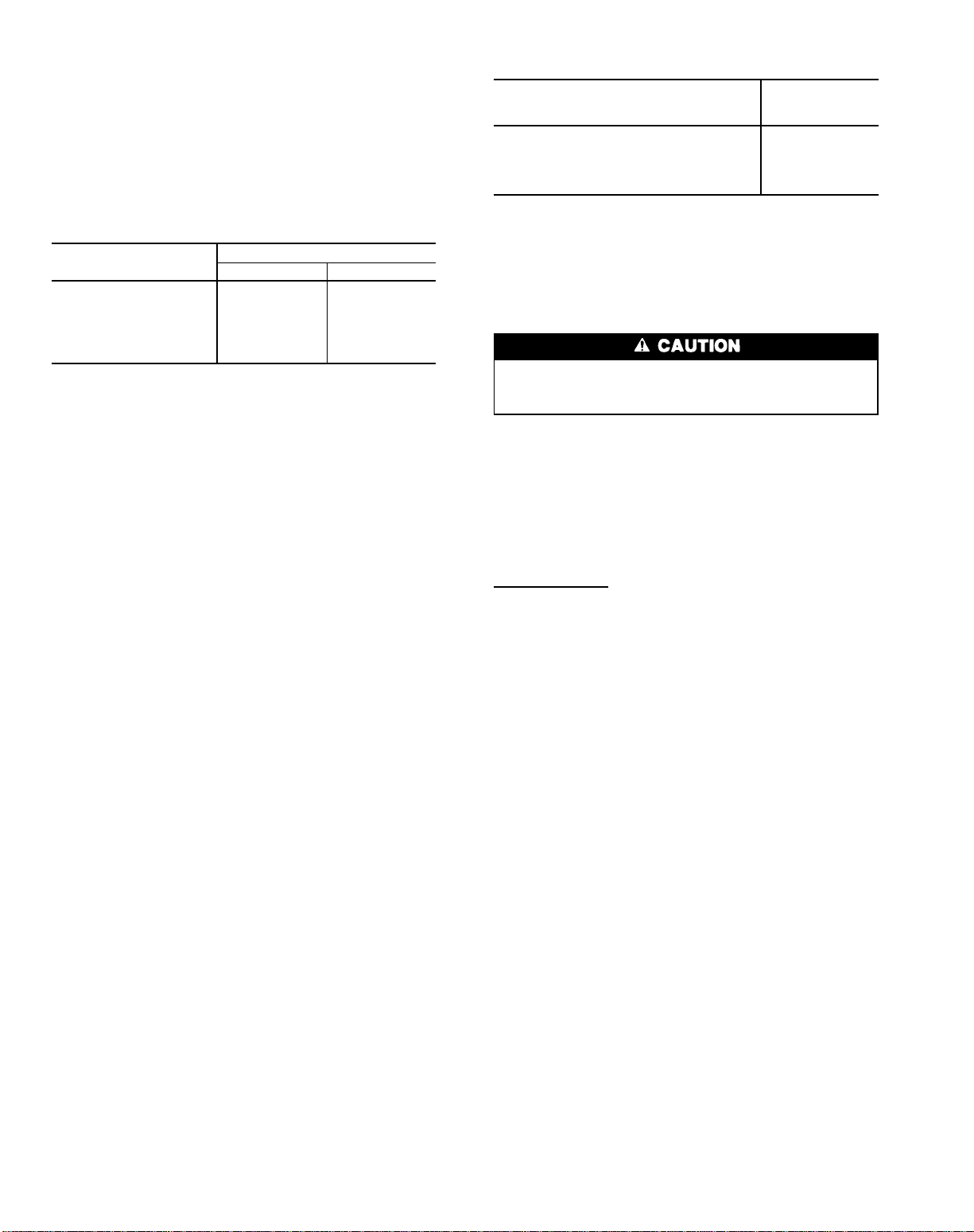
Filter Status Switch — The filter status switch (FLTS)
is factory-installed in the filter section on all PIC-equipped
units. The switch is a snap-acting SPDT switch. When dirty
filter elements cause the pressure drop across the filter media to exceed the switch setting, the switch closes and sends
an alarm signal to the PIC.
The 39L units use a single switch. In 39NX units, up to
3 switches can be connected in parallel. When the switches
are wired in parallel, it is not possible to isolate an alarm
signal to a single switch.
The FLTS has an operating range of 0.05 to 2.0 in. wg.
Factory settings for the switch are as follows:
Filter Type
Setting (in. wg)
Flat 0.5
Bag/Cartridge 1.0
Final 1.5
The FLTS electrical ratings are as follows:
300 va pilot duty at 115 to 277 vac
10 amps non-inductive to 277 vac
Rated for NO (normally open) and NC (normally closed)
contacts.
High-Pressure Switch (Fig. 38) — The high-
pressure switch (HPS) is factory installed in the PIC control
box on VAV units only. It is a snap-acting SPDT switch with
manual reset that is used to shut down the supply fan whenever the duct pressure reaches the switch setting. The manual
reset is used to restart the fan after the problem has been
corrected.
The switch is factory set at 3.0 in. wg. It has a range of
1.4 to 5.5 in. wg and can be field adjusted for specific
applications.
Adjust the high-pressure switch setting as follows:
1. Loosen conduit enclosure retaining screw, pull firmly on
the bottom end and snap off cover.
2. Raise set point by turning slotted adjustment screw
(located at top of range spring housing) clockwise. Turn
adjustment screw counterclockwise to lower set point.
3. To change or check calibration, use a T assembly with
3 rubber tubing leads. Attach one lead to the HPS and
another to an accurate manometer with the appropriate
range. Apply pressure through the third lead and approach set point slowly.
4. Adjust set point to at least 0.5 in. wg greater than configured static pressure set point.
Air Quality Sensors (Fig. 39) — The air quality (AQ)
sensors are shipped inside the fan section for field installation. Two types of sensors are supplied; one sensor monitors
the conditioned air space, and the other sensor monitors the
return air duct. Both sensors use infrared technology to detect the levels of CO2present in the air.
Sensor descriptions and part numbers are shown in
Table 6. To mount the sensor, refer to the installation instructions shipped with the sensor.
Table6—CO
2
Sensor Accessories
CO2SENSOR ACCESSORY
PART NUMBERS
DESCRIPTION
CGCDXSEN001A00 Wall Mount Sensor (No Display)
CGCDXSEN002A00 Wall Mount Sensor with Display
CGCDXSEN003A00 Duct Mount Sensor (No Display)
CGCDXGAS001A00 Sensor Cal bration Service Kit
CGCDXPRM001A00 User Interface Program (UIP)
The CO2sensors listed in Table 6 are all factory set for a
range of 0 to 2000 ppm and a linear voltage output of 2 to
10 vdc. Fig. 40 shows ventilation rates for various CO2set
points when outside air with a typical CO2level of 350 ppm
is used to dilute the indoor air. Refer to the instructions supplied with the CO2sensor for electrical requirements and
terminal locations.
Any changes to the sensor’s factory configuration require
the purchase of the User Interface Program (UIP) or Sensor
Calibration Service Kit, which also contains the UIP.
To accurately monitor the quality of the air in the conditioned air space, locate the sensor near the return air grille
so it senses the concentration of CO
2
leaving the space. The
sensor should be mounted at least 1 ft above or 1 ft below
the thermostat to avoid direct breath contact.
Do not mount the space sensor in drafty areas such as near
supply ducts, open windows, fans, or over heat sources. Allow at least 3 ft between the sensor and any corner. Avoid
mounting the sensor where it is influenced by the supply air;
the sensor gives inaccurate readings if the supply air is blown
directly onto the sensor or if the supply air does not have a
chance to mix with the room air before it is drawn into the
return air stream.
To accurately monitor the quality of the air in the return
air duct, locate the sensor at least 6 in. upstream or 15 in.
downstream of a 90 degree turn in the duct. The downstream
location is preferred. Mount the sensor in the center of the
duct.
If the sensor is mounted in the return air duct, readjust the
mixed-air dampers to allow a small amount of air to flow
past the return air damper whenever the mixing box is fully
open to the outside air. If the damper is not properly adjusted to provide this minimum airflow, the sensor may not
detect the indoor-air quality during the economizer cycle.
Fig. 38 — High-Pressure Switch (P/N HH02WC001)
49
Page 50

Fig. 39 — Air Quality (CO2) Sensor
IN
24 Vac.
OUT
-
+
PRESSURE
LO
HI
SPAN
ZERO
PRESSURE TRANSDUCER :
Part Number :
Range : 0 -
0 . 1 in.
of water
CARRIER
CORPORATION
T40 - 001C - 04 - 012
9A32201
(Wall Mount Version Shown)
CO2CONCENTRATION (PPM)
Fig. 40 — Ventilation Rates Based on CO2Set Point
Constant Outside Air (OAC) Control — This fea-
ture ensures a continuous supply of outside air to the unit
and occupied space. The OAC control monitors the outside
air velocity pressure (OAVP) with a probe and pressure transducer.The pressure transducer is factory-installed; the probe
is factory-supplied for field installation in the outside air ducts.
See Fig. 41 and 42.
PROBE INSTALLATION — Locate each probe in a straight
portion of the outside air duct with any dampers, elbows, or
fittings at least 2 diameters away. The probe should be in a
portion of the duct where the airflow is uniform, so that the
probe senses the average air velocity in the duct. The probe
must also be located so that measurements at the probe are
not influenced by the opening or closing of the outdoor-air
dampers.
Install the probe at a 90 degree angle to the airflow and
ensure that the holes in the probe are facing and in line with
the airflow. The probe tube that is closest to the incoming
airflow measures velocity pressure; the rear tube measures
duct static pressure. Use approved plenum tubing to connect
the probe to the bulkhead fittings on top of the control box.
For runs up to 150 ft, use
150 ft, use3⁄8-in. OD tubing. Use at least 25 ft of tubing to
prevent pulsations and erratic operation. Coil any extra tubing if necessary.
If the outside air duct is large, additional probes can be
installed in the duct and manifolded to obtain a more accurate velocity pressure reading for the entire duct. Manifold
tubing must be larger than the plenum tubing connecting the
manifold to the control box. See Fig. 43 and the preceding
for recommended tube sizes.
1
⁄4-in. OD tubing. For runs over
Fig. 41 — OAVP Transducer (P/N HK05ZG004)
Fig. 42 — OAVP Probe (P/N 35DN40007001)
NOTE:High-pressuremanifoldconnectionsshown. Low-pressure connections are identical and must duplicate high-pressure connections.
Fig. 43 — Probe Manifolding
50
Page 51

OAC CALIBRATION — Once the probe and tubing are installed, input the set point to match the probe readings. Before adjusting the OAVP probe, ensure that the supply-air
fan is providing the maximum design airflow and that the
outside-air dampers are adjusted for the design outdoor
airflow intake.
To calibrate the PIC processor to match the probe location, use a precision manometer to measure the velocity pressure in the outdoor air duct at design conditions. Use the
HSIO (local interface device) or Building Supervisor to input the value as the OAVP set point.
Note that the probe does not measure true velocity pressure; when positioned as recommended, the probe measures
a velocity pressure 1.563 times that of the velocity pressure
in the duct. This multiplier (magnification) factor varies with
the probe’s location, and can even be negative if the probe
is located at an elbow or turn. All OAVPvalues displayed on
the HSIO incorporate the multiplier factor to show the true
duct velocity pressure.
If a precision manometer is not available, read the velocity pressure value at the HSIO when the system is running
at maximum design airflow and input that value as the set
point. During normal operation, the velocity pressure is held
constant as the supply fan modulates.
USING OAVP VALUES TO DETERMINE DUCT AIRFLOW — It is possible to determine the airflow (cfm) in the
outside air duct based on the readings obtained by the OAVP
probe. See the following procedure.
Use the HSIO and status function ( ) to display
the outside air velocity pressure (Pv) at the transducer.
If the airflow obtained by the preceding method is different from the design airflow or a measurement obtained with
a balancer, the OAVP probe is not sensing the average duct
velocity and/or the probe’s multiplier factor is effectivelynot
1.563. To match the design or measured airflow to the airflow determined with the preceding formulas, relocate
the probe as recommended or use the HSIO and service
function ( ) to change the probe multiplier
factor.
FIELD-SUPPLIED OR HIGH-VELOCITY PRESSURE
TRANSDUCERS — The default pressure transducer installed at the factory (P/N HK05ZG004) has a range of 0.00
to 0.05 in. wg, which matches an air velocity range of approximately 225 to 680 fpm. The maximum velocity for optimum OAC operation and response, however, is 620 fpm.
If the average duct air velocity is greater than 620 fpm, use
one of the alternate transducers shown in Table 7.
For a field-supplied pressure transducer, use the service
function ( ) to configure the OAC control with
the transducer’s specifications:
OALV = Transducer minimum output voltage
OAHV = Transducer maximum output voltage
OALR = Transducer low pressure
(range minimum output) value
OAHR = Transducer high pressure
(range maximum output) value
Find the average velocity (V) in the duct, in fpm:
4005
=Pv = V
Obtain the cross-sectional area of the duct in sq ft. (A). To
determine the airflow (F) in the duct, in cfm:
VxA=F
Table 7 — OAC Pressure Transducers
INDICATED VELOCITY
CARRIER
PART NO.
HK05ZG004 T40-005C-04-013 0.00 — 0.05 0.013 — 0.037 0.005 — 0.045 0.008 — 0.024 0.003 — 0.029 360 — 620 225 — 680
HK05ZG005 T40-001C-04-012 0.00 — 0.10 0.025 — 0.075 0.010 — 0.090 0.016 — 0.048 0.006 — 0.057 505 — 875 320 — 960
HK05ZG006 T40-003C-04-015 0.00 — 0.30 0.075 — 0.225 0.030 — 0.270 0.048 — 0.144 0.019 — 0.173 875 — 1520 555 — 1665
MODUS PART
NO.
RANGE
(in. wg)
PRESSURE AT
TRANSDUCER (in. wg)
Optimum
Range
Theoretical
Range
TRUE VELOCITY PRESSURE
IN DUCT (in. wg)
Optimum
Range
Theoretical
Range
VELOCITY IN DUCT
(fpm)
Optimum
Range
Theoretical
Range
51
Page 52
Field Wiring Connections — All field wiring must
comply with National Electric Code (NEC) and all local requirements. The recommended wiring is as follows:
Dampers, actuators, — 4-conductor 20 AWG cable
and valves (2 twisted pairs, unshielded)
Sensors — 2-conductor 20 AWG cable
(one twisted pair, unshielded)
Refer to Table 8 for recommended brands and part
numbers.
Table 8 — Recommended Sensor and
Device Wiring
MANUFACTURER
PART NUMBER
Regular* Plenum*
Alpha 1895 —
American A21501 A48301
Belden 8205 88442
Columbia D6451 —
Manhattan M13402 M64430
Quabik 6130 —
*Within a building.
NOTE: Wiring is 20 gage, 2-conductor twisted cable.
REMOTE LOCAL INTERFACE DEVICE (HSIO) — When
ordered as part of a 39L or 39NX unit, the HSIO is factoryinstalled and fully wired.
To reinstall the HSIO in a remote location away from the
control box, refer to the factory wiring connections in
Fig. 9-12 and proceed as follows:
1. Use a 20 AWG 2-conductor twisted wire pair (Belden
No. 8205 or equivalent) to supply power to the HSIO module. Use a 20AWG 3-conductor cable shielded with drain
wire (Belden No. 8772 or equivalent) for communication
with the HSIO. Cable length must not exceed 1000 ft.
2. Pull the 2 cables (power and signal) through the electri-
cal conduit to the NEMA standard box or HSIO. Leave
approximately 4 ft of wire in the PIC control box for
terminations.
3. Route the cables from the PIC control box to the HSIO
bracket. Secure the HSIO cables to the existing cables
using either tie wraps or by twisting the HSIO cables around
the existing cables. Strip back the jacket 6 in. on each
cable after cutting off the excess. Connect the power cable
at the PIC control box to the existing 3-pin connector hanging at the HSIO bracket. The wires should be terminated
in the screw-type locking clamps on Terminals 1 and 2.
4. Connect the signal cable at the PIC control box to the
existing 4-pin communications connector hanging at the
HSIO bracket. The wires should be terminated in the locking clamps on Terminals 1, 2, and 3. The shield should be
terminated at the HSIO bracket (ground). Be sure to note
the color coding used on the cable for later reference when
terminating the other end of the cable.
5. At the NEMA standard box or HSIO, connect the power
conductors to Pin 1 and 2 of the 3-pin plug. Using the
color coding from the above step, connect the signal cable
to Pin 1, Pin 2, and Pin 3 of the 4-pin communications
connector. Remove the shield and drain wire from this
end of the cable.
6. After the HSIO is installed inside the remote cover, con-
nect the 4-pin and 3-pin plugs to the HSIO.
RETURN-AIR TEMPERATURE SENSOR, OUTDOORAIR TEMPERATURE SENSOR, ENTHALPY SWITCH,
AND MIXED-AIR TEMPERATURESENSOR — Wires are
to be connected to the proper terminals on the processor module. See Fig. 44 for details.
Select a 20 AWG twisted pair, no shield cable. Connect as
per table below:
SENSOR
PROCESSOR
MODULE
PIN NO.
Return-air temperature sensor (RAT) 20 and 21
Outside-air temperature sensor (OAT) 5 and 6
Enthalpy switch (ENT) 34 and TB2-3
Mixed-air temperature sensor (MAT) 8 and 9
Space temperature sensor (SPT) 17 and 18
NOTE: The MAT is factory wired on all units with a factory-installed
mixing box, filter mixing box, or air blender.
SPACETEMPERATURESENSOR (SPT) —The space temperature sensor cover includes terminal block TB1, a jumper
between Pin E2 and Pin E3, and an RJ11 female connector.
The RJ11 female connector connects the service tool with
the Carrier Comfort Network.
Jumper MUST be in place between Pin E2 and Pin E3
or inaccurate readings could result. Ensure that the jumper
is in place before installing the sensor.
Using a 20 AWG twisted pair conductor cable rated for
the application, connect one wire of the twisted pair to
Terminal T1 and connect the other wire to Terminal T2 on
TB1. See Fig. 45.
The other ends of the wires are connected to the processor
(PSIO master) module. As polarity is not a consideration,
connect one wire to Terminal 17 and one wire to Terminal
18 of the processor module.
RJ11 Plug Wiring — Refer to the Carrier Comfort Network
Interface, page 64, for communication bus wiring and cable
selection. The cable selected must be identical to the CCN
communication bus wire used for the entire network.
Cut the CCN wire and strip the ends of the RED, WHITE,
and BLACK conductors. Insert and secure the RED ( ) wire
to Pin J2 of the SPT terminal strip TB1. Insert and secure the
WHITE (ground) wire to Pin J3 of the SPT terminal strip
TB1. Insert and secure the BLACK (−) wire to Pin J5 of
SPT terminal strip TB1.
The other end of the communication bus cable must be
connected to the remainder of the CCN communication bus
at the COMM1 plug on the processor (PSIO master) module. Refer to Carrier Comfort Network Interface section,
page 64, for more details.
DAMPERACTUATORS— The PIC processor can activate
a field-installed modulating exhaust/relief damper. This is
achieved by wiring the factory-supplied damper actuator in
series with the factory-supplied and field-installed mixing
box damper actuator.
The PIC processor can also activate a field-installed damper
actuator mounted in a field-supplied mixing box. These actuators are available from the factory when ordered as an
option with the unit.
See Table 9 for recommended actuators.
NOTE: The actuator selected must be capable of receiving
a 4 to 20 mA signal and must have a total impedance of less
than 250 ohms. Wire should be 20 gage minimum, twistedpair type and rated for the application.
52
Page 53

For factory-supplied actuators that are field-installed, the
24 vac power source is included with the unit wired in the
control box. For field-supplied actuators, a 24 vac power source
must be field-supplied and installed for each actuator.
To prevent equipment damage: Power must NOT be connected to an earth ground; actuator case must NOT be
connected to control input terminals.
Field-Supplied Exhaust Damper — Wire the 4 to 20 mAsignal of the factory-supplied exhaust damper actuator as follows (Fig. 46):
1. Select a 20 AWG twisted pair conductor cable rated for
the application. Identify the positive ( ) and negative (−)
signal contacts on the actuator.
2. Install cable from the actuator to the PIC control box.
3. Remove jumper no. 84 from between terminals TB2, 7
and 8. Connect positive ( ) lead to terminal 8 of TB2.
Connect negative (−) lead to terminal 7 of TB2.
Field-Supplied Modulating Mixing Box — Wire the 4 to
20 mA signal of the factory-supplied damper actuator as follows (Fig. 47):
1. Select a 20 AWG twisted pair conductor cable rated
for the application. Identify the positive ( ) and
negative (−) signal contacts on the actuator.
2. Install cable from the actuator to the PIC control box.
3a. For the outside-air damper (OAD) actuator, connect the
positive ( ) lead to pin 40 of the processor module. Connect the negative (−) lead to terminal 6 of terminal block
2 (TB2).
b. If the actuator is factory-supplied, connect the actua-
tor’s 24 vac power wires to TB2, terminals 19 and 20.
If the actuator is field-supplied, connect the power wires
to a separate, isolated 24 vac power source.
LEGEND
ENT — Enthalpy Switch
MAT — Mixed-Air Temperature Sensor
OAT — Outside-Air Temperature Sensor
RAT — Return-Air Temperature Sensor
SPT — Space Temperature Sensor
Field Wiring
NOTE: Connections for 39NX with integral PIC shown. See wiring diagrams in
Fig. 9 and 12 for terminal connections in 39L control box and all remote-mount
control boxes.
Fig. 44 — Field Wiring of Sensors
IMPORTANT: Jumper may be connected from E1 to E3. Move jumper to
connect E2and E3 before installingsensor,otherwise incorrectspacetemperature values are generated.
Fig. 45 — Space Temperature Sensor Wiring
53
Page 54

Table 9 — Recommended Actuators
PART
NO.
VOLTAGE
(50/60 Hz)
VA (24 vac)
IMPEDANCE
(Ohms)
SIGNAL INPUT
(mA)
DAMPER AREA
(sq ft)
TORQUE
(in.-lb)
STROKE
Parallel Opposed
HF27BB006 24 18 82.5 4 to 20 8.4 10.8 15 2 in.
HY27BB001* 24 60 250.0 4 to 20 42 54 50 180°
HF27BB010 24 44 82.5 4 to 20 106 137 190 3
1
⁄2in.
*Shipped with drive HF39CB001, which must be field-installed on actuator.
NOTES:
1. All actuators are spring return.
2. Damper arearatings are nominal and arebased on standard (NOTlow leak)
dampers at 1.0 in. wg pressure and 2000 fpm velocity.
3. Actuator wire coding is as follows:
HF27BB006 - BLACK and WHITE (24 vac)
RED ( signal)
GREEN (− signal)
HY27BB001 - BLACK and WHITE (24 vac)
ORANGE ( signal)
BLUE (− signal)
HF27BB010 - WHITE/BLUE and BLACK (24 vac)
RED ( signal)
GREEN (− signal)
4. Actuator HH27BB006 is equipped with 20 ft of plenum cable. Wires for actuators HY27BB001 and HF27BB010 are in the actuator junction box.
5. Actuators are available as an option when ordered with the unit.
4a. For the return-air damper (RAD) actuator, connect the
positive ( ) lead to TB2, terminal 6. Connect the negative (−) lead to TB2, terminal 7.
b. If the actuator is factory-supplied, connect the actua-
tor’s 24 vac power wires to TB2, terminals 21 and 22.
If the actuator is field supplied, connect the power wires
to a separate, isolated 24 vac power source.
Field-Supplied Two-Position Damper — The factorysupplied SPDT relay must be field-installed and wired. The
relay contacts are rated as follows:
48 va at 24 vac and .25 service factor
125 va at 115 vac and .25 service factor
125 va at 230 vac and .25 service factor
The relay provides a set of contacts (normally open and normally closed) using no. 6 screw terminals; the 24 vdc coil
connections are through
1
⁄4-in. quick connects.
Using a 20AWG twisted cable, connect the relay coil contacts 1 and 2 to the processor module pins 41 and 42. See
Fig. 48.
To connect the field-supplied two-position damper actuator (Fig. 48): Connect one contact of the actuator to the
normally-open contact of the relay .Connectthe common contact of the relay to one leg of the power source. Connect the
other contact of the actuator to the other leg of the power
source.
SMOKE CONTROL OPTION — The smoke control option
includes 3 relays which control the 4 different modes of the
option. These relays are factory wired.Terminalblock 5 (TB5)
provides an easy means to wire the field-supplied smoke control panel to the PIC controller on the 39L or 39NX unit. See
Fig. 49 and 50.
The approved building fire alarm system must provide 4
different normally-open dry contact closures. A fieldsupplied 24 vac, double-pole, double-throw (DPDT) fire shutdown (FSD) relay rated for the application (240 vac with a
10 amp minimum) is required.
All power going through the smoke control panel dry contacts and the FSD relay coil is furnished by the PIC control
box. A 24 vac fused power source uses a factory-installed
3 amp in-line fuse. See Fig. 49 or 50 for smoke control option wiring details.
Wire as follows:
1. Disconnect all power at the unit, PIC control box,
return fan (if applicable), and fire panel.
2. Wire the supply fan motor starter per Fig. 8.
3. If applicable, wire the return fan as shown in Fig. 49 or
50.
NOTE: Return fan power may be different from supply
fan power.
4. Connect leads from the return fan HOA switch to
terminals 9 and 10 of TB5.
5. Wire the first set of contacts of the DPDT FSD. For fire
shutdown of the unit from a local smoke detector, wire
ONLYthe normally-closed contacts (NEC, class 1 power
rated) to the hot leg of the fan power supply and terminal 2 of TB1.
6. Terminal 8 of TB5 is internally connected to ground.
Connect one side of the EVAC, PURG, and PRES dry
contacts of the smoke control panel to terminal 8 of TB5.
7. Connect the other side of the PRES dry contact to terminal 3 of TB5. Connect the other side of the PURG
dry contact to terminal 4 of TB5. Connect the other side
of the EVAC dry contact to terminal 5 of TB5.
8. Connect the normally-open dry contacts of the FSD device (smoke detector with auxilary relay and/or smoke
control panel dry contact set) to terminal 1 and 2 of TB5.
9. Connect the 24 vac relay coil of the FSD relay to terminals 1 and 8 of TB5.
10. Connect the second pole of the FSD relay to the hot leg
of the return fan power supply and to terminal 11 of TB5.
Refer to Fig. 49 or 50 for point-to-point wiring of the smoke
control option inside the PIC control box.
Fig. 46 — Exhaust Damper Actuator Wiring (Smoke
Control Option or Modulating Dampers)
LEGEND
Field Wiring
EXD — Exhaust Air
Damper Actuator
54
Page 55

LEGEND
OAD — Outside Air Damper
RAD — Return Air Damper
NOTE: Connections for 39NX with integral PIC shown. See wiring diagrams in
Fig. 9 and 12 for terminal connections in 39L control box and all remote-mount
control boxes.
Actuator
Actuator
Factory Wiring
Field Wiring
Fig. 47 — Field-Supplied Mixing Box Actuator Signal Wiring
*Field-installed if only outside air damper is used.
LEGEND
OAD — Outside Air Damper
Actuator
Field Wiring
Fig. 48 — Field-Supplied Two-Position Damper Relay and Actuator Wiring
55
Page 56

LEGEND
AO — Analog Output
EVAC — Evacuation
EXD — Exhaust Air Damper Actuator
FSD — Fire Shut Down
HOA — HAND/OFF/AUTO Switch
HPS — High-Pressure Switch
LTT — Low Temperature Thermostat
OAD — Outside Air Damper Actuator
PRES — Pressurization
RAD — Return Air Damper Actuator
NOTE: The return fan power circuit may be different than the supply
fan starter power.
RFR — Return Fan Relay
SF — Supply Fan Contactor
SFR — Supply Fan Relay
TB — Terminal Block
TRAN — Transformer
Fig. 49 — Smoke Control Option Wiring Schematic (39L)
56
Remove Jumper
Factory Wiring
Field Wiring
Page 57

LEGEND
AO — Analog Output
EVAC — Evacuation
EXD — Exhaust Air Damper Actuator
FSD — Fire Shut Down
HOA — HAND/OFF/AUTO Switch
HPS — High-Pressure Switch
LTT — Low Temperature Thermostat
OAD — Outside Air Damper Actuator
PRES — Pressurization
RAD — Return Air Damper Actuator
*Factory installed and wired if ordered with exhaust box.
NOTE: Return fan power circuit may be different than the supply fan
starter power.
RFR — Return Fan Relay
SF — Supply Fan Contactor
SFR — Supply Fan Relay
TB — Terminal Block
TRAN — Transformer
Fig. 50 — Smoke Control Option Wiring Schematic (39NX)
57
Factory Wiring
Field Wiring
Page 58

ANALOG DEVICE FOR ANALOG OUTPUTTEMPERATURE CONTROL — The analog controlled device selected
must be capable of receivinga4to20mAsignal. Its internal
impedance must not exceed 600 ohms.
The power supply of the analog device must be field in-
stalled.
Using a 20 AWG twisted wire pair, wire the control signal
as follows (Fig. 51).
1. Connect the positive ( ) contact to pin 46 of the option
module.
2. Connect the negative (−) contact to pin 47 of the option
module.
DEVICE UNDER DISCRETE OUTPUT TEMPERATURE
CONTROL—The factory-supplied SPDT relay must be field
installed and wired. See Fig. 52. The relay contacts are rated
as follows:
48 va at 24 vac and .25 power factor
125 va at 115 vac and .25 power factor
125 va at 230 vac and .25 power factor
The relay provides a set of contacts (normally open and normally closed) using no. 6 screw terminals while the 24 vdc
coil connections are through
1
⁄4-in. quick connects.
Using a 20AWG twisted cable, connect the relay coil contacts 1 and 2 to the option module pins 50 and 51. Connect
the device to be controlled to the normally-open or normallyclosed contacts of the relay. Pay close attention to the contact ratings listed above. See Fig. 53.
DISCRETE OUTPUT DEVICE UNDER TIMECLOCK
CONTROL—The factory-supplied SPDT relay must be field
installed and wired. (Fig. 52.) The relay contacts are rated as
follows:
48 va at 24 vac and .25 power factor
125 va at 115 vac and .25 power factor
125 va at 230 vac and .25 power factor
The relay provides a set of contacts (normally open and normally closed) using no. 6 screw terminals while the 24 vdc
coil connections are through
1
⁄4-in. quick connects.
Using a 20AWG twisted cable, connect the relay coil contacts to the option module pins 53 and 54. Connect the device to be controlled to the normally-open or normallyclosed contacts of the relay.Pay close attention to the contact
ratings listed above. See Fig. 54.
Field Wiring
Fig. 51 — Wiring of Analog Device for Analog Output Temperature Control
NC
SDA 2 02 0
COM
NO
1
COI L
2
Fig. 52 — Single-Pole, Double-Throw (SPDT) Relay
58
Page 59

HUMIDIFICATION DEVICES
Modulating Valve for Analog Output Humidity Control
(Fig. 55) — Valve selected must be able to receivea4to
20 mA signal and must NOTexceed an impedance of600 ohms.
Valve power supply must be field-installed and isolated.
Install valve on humidifier piping and connect actuator power
supply.Using a 20 AWG twisted wire pair, connect the positive ( ) contact of the valve actuator to pin 40 of the option
module. Connect the negative (−) contact of the valve actuator to pin 41 of the option module.
Two-Stage Humidification Control Relays — Two SPDT
relays with silver cadmium contacts are shipped with the unit
when 2-stage humidification control is requested. See
Fig. 52. The relays are rated as follows:
48 va at 24 vac and .25 power factor
125 va at 115 vac and .25 power factor
125 va at 230 vac and .25 power factor
The relays must be field installed within a field-supplied enclosure rated for the application.
Wire the stage 1 relay as follows: Connect the 24 vac coil
contacts 1 and 2 to pins 41 and 42 of the option module. The
stage 1 relay is intended to open a normally-closed steam
valve and not energize the spray pump. See Fig. 56 for field
wiring of the stage 1 valve and steam pump.
Wire the stage 2 relay as follows: Connect the 24 vac coil
contacts 1 and 2 to pins 44 and 45 of the option module. The
stage 2 relay is intended to open a second normally-closed
steam valve. See Fig. 56 for field wiring of the stage 2 valve.
Duct High Humidity Switch — The humidistat is factory supplied and field installed. It is shipped (with a template) in its
own box.
All wiring must comply with applicable local codes and
ordinances. Wire the DHH as follows:
1. Turn switch on PIC control box to OFF.
Turn switch on PIC control box to OFF before connecting DHH wiring, otherwise electrical shock or
equipment damage can result.
2. Connect wire from terminal 3 of terminal block 2 (TB2)
to the terminal labeled ORANGE on the DHH sensor. See
Fig. 57.
3. Connect wire from pin 7 of the option module to the sen-
sor screw terminal labelled RED.
During humidification, the duct high humidity switch must
be set to the maximum humidity level desired in the supply
duct (80% minimum).
Duct Mounted/Wall Mounted Relative Humidity Transmitter (Fig. 58) — Identify the power terminal block (ACIN)
and signal terminal block (OUT). See Fig. 59 and 60. Using
20 AWG twisted wire pair, connect the 24 vac power to the
terminal labeled ACIN.
Field Wiring
NOTE: The relay furnished is a SPDT relay with silver cadmium oxide contacts, rated as follows:
48 va at 24 vac and .25 power factor
125 va at 115 vac and .25 power factor
125 va at 230 vac and .25 power factor
Fig. 53 — Wiring of Device Under Discrete Output
Temperature Control
Field Wiring
NOTE: The relay furnished is a SPDT relay with silver cadmium oxide contacts, rated as follows:
48 va at 24 vac and .25 power factor
125 va at 115 vac and .25 power factor
125 va at 230 vac and .25 power factor
Fig. 54 — Wiring of Discrete Output Device
Under Timeclock Control
Field Wiring
Fig. 55 — Wiring of the Modulating Valve for
Analog Output Humidity Control
59
Page 60
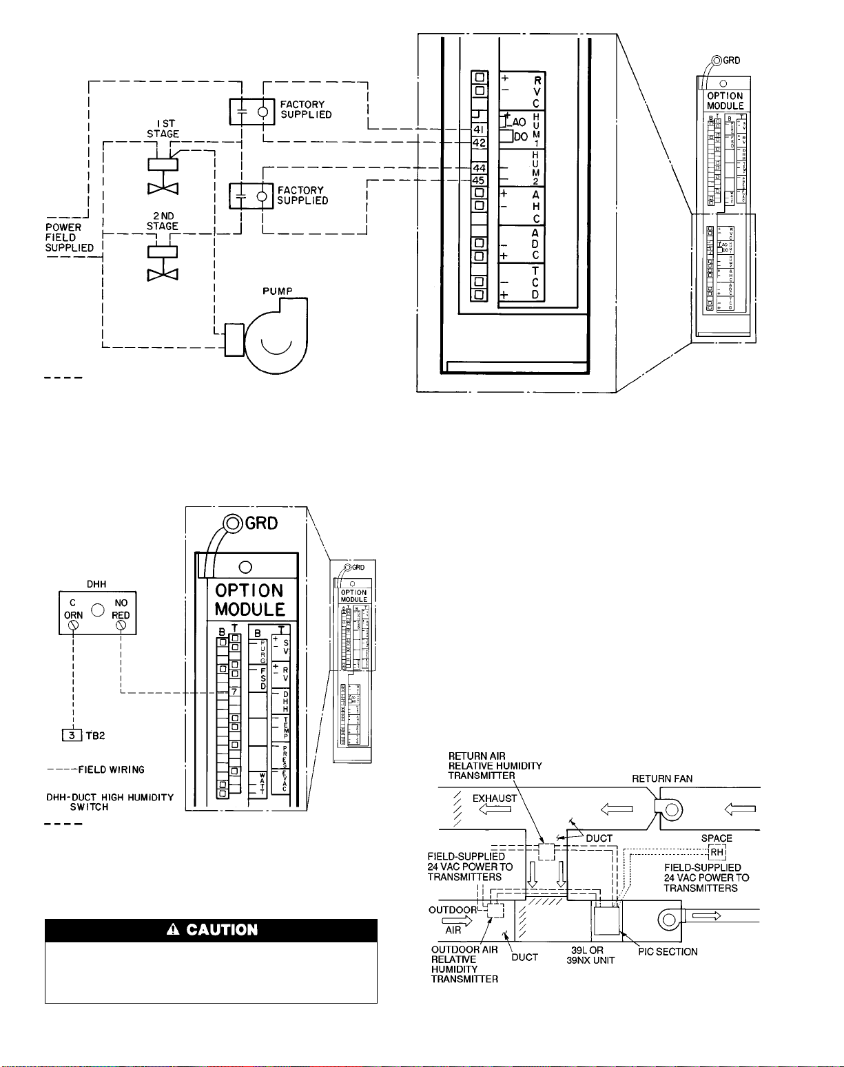
The 24 vac power source(s) to both duct mounted and
wall mounted relative humidity transmitters MUST be
isolated. Connecting either side to a ground will permanently damage the sensor.
The power for the relative humidity transmitters may be
sourced from the valve 24 vac power source at wire no. 6
and 7 or at wire no. 4 and 5.
Connect the signal wires as follows: Secure one wire to
the terminal labelled OUT (located at the right of terminal
block OUT). Secure the other wire to the negative signal
output terminal (terminal adjacent to the terminal labelled
OUT ). Run the twisted pair of signal wires to the PIC
control box. Observe all local code requirements.
Outdoor Relative Humidity Transmitter: Connect the positive ( ) wire to pin 31 of the processor module. Connect the
negative (−) wire to pin 32 of the processor module.
Return Air or Space Relative Humidity Transmitter;
Connect the positive ( ) wire to pin 10 of the processor module. Connect the negative (−) wire to pin 11 of the processor
module. See Fig. 61.
Field Wiring
NOTE: The relay furnished is a SPDT relay with silver cadmium oxide contacts, rated as follows:
48 va at 24 vac and .25 power factor
125 va at 115 vac and 25 power factor
125 va at 230 vac and .25 power factor
Fig. 56 — Wiring of Two-Stage Humidification Control Relays
Field Wiring
NOTE: Connections for 39NX with integral PIC shown. See wiring diagrams in
Fig. 9 and 12 for terminal connections in 39L control box and all remote-mount
control boxes.
Fig. 57 — Wiring of the Duct
High Humidity Switch
Fig. 58 — Field-Installed Relative
Humidity Transmitters
60
Page 61
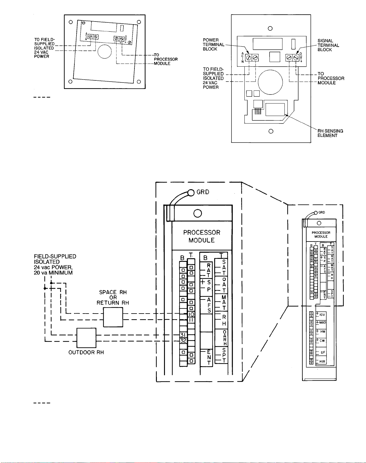
Field Wiring
Fig. 59 — Duct Mounted Relative Humidity
Transmitter Wiring
Fig. 60 — Wall Mounted Relative Humidity
Transmitter Wiring
LEGEND
RH — Relative Humidity
Field Wiring
Fig. 61 — Wiring of Relative Humidity Transmitters
61
Page 62

AIR QUALITY SENSOR — Air quality (AQ) sensors are
CO2sensors shipped inside the fan section for field installation. To wire the sensors after they are mounted in the conditioned air space and return air duct, see Fig. 62 and the
instructions shipped with the sensors. For each sensor, use
two 2-conductor 20 AWG twisted-pair cables (unshielded)
to connect the separate 24 vac power source to the sensor
and the sensor to the option module (PSIO slave) terminals.
To connect each AQ sensor to the option module, identify
the positive ( ) and negative (−) terminals on the sensor;
connect AQ1 to terminals 25 and 26 and connect AQ2 to
terminals 28 and 29.
OUTSIDE AIR VELOCITY PRESSURE (OAVP) SENSOR — The OAVP sensor is factory installed and wired. As
shown in Fig. 62, the sensor’s power wiring is connected to
TB2, 9 and 10 for 39L units or TB2, 29 and 30 for 39NX
units; the signal leads are connected to terminals 31 and 32
in the option module.
FAN VOLUME CONTROL (Fig. 63)
Airflow Monitoring Stations are field-selected and field-
installed in the supply and return air ducts; see Fig. 63.
Install each monitoring station in a straight portion of the
duct with any upstream or downstream elbows or fittings at
least 2.5 diameters away.
Use approved plenum tubing to connect each monitoring
station to the bulkhead fittings on top of the control box. For
runs up to 50 ft, use
1
⁄4-in. OD tubing. For runs over 50 ft,
use3⁄8-in. OD tubing.
DifferentialPressure Transducers for fan volume control are
factory-installed in the control box (two are supplied). The
power supply for the transducers is also factory installed.
Both transducers have pressure ranges of 0.0 to 1.0 in. wg
and produce 2 to 10 vdc signals. See Fig. 64 for wiring
details.
Note that if the velocity pressure of the supply and/or return air is below 0.75 in. wg, the system may require transducers with lower ranges than those of the default factorysupplied transducers. As a general rule, size transducers
so that the maximum air velocity pressure is 75% of the
transducer’s maximum value. For example, if the 39L or
39NX unit produces a maximum air velocity pressure of
0.15 in. wg, a transducer with a maximum value of
0.20 in. wg can be used. Sizing the transducers according to
these guidelines ensures that they have good resolution.
Factory-Supplied Return Fans with Inlet Guide Vanes
(IGVs) are factory wired except for the air supply control
signal from the airflow monitoring stations, which is connected in the field to the bulkhead fitting.
Return Fans with Field-Supplied IGVActuators must be able
to receivea4to20mAsignal and may NOT have an impedance of more than 600 ohms. An isolated power source
must be field-supplied and installed. See Table 9 for
recommended actuators.
To install actuators, see Fig. 65. Using a 2-conductor
20AWG conductor cable (one twisted pair, unshielded) rated
for the application, connect the positive ( ) wire to terminal
37 in the option module. Connect the negative (−) wire to
terminal 38. Connect the 24 vac power leads to TB2,
terminals 23 and 24.
Field-Supplied Return Fans with Variable Frequency Drives
must have 4 to 20 mA signal input boards and their own
field-supplied and installed power sources.
To install return fans with variable frequency drives,
see Fig. 66. Using a 2-conductor 20 AWG conductor cable
(one twisted pair, unshielded) rated for the application, connect the positive ( ) signal wire to terminal 37 in the
option module. Connect the negative signal (−) wire to
terminal 38.
The supply fan minimum set point must be equal to the
return fan minimum airflow, plus the delta airflow that is to
be maintained.
LEGEND
AQ — Air Quality Sensor
OAVP — Outside Air Velocity Pressure Sensor
Field Wiring
Factory Wiring
NOTE: See unit label diagram or Fig. 12 for remote-mount control
box connections.
Fig. 62 — Air Quality and OAVP Sensor Wiring
IGV — Inlet Guide Vane
Field Wiring
NOTE: Air monitoring stations are field supplied and installed; pressure transducers are factory supplied and installed.
Fig. 63 — Field-Installed Fan Volume Control
62
Page 63

LEGEND
RVP — Return Velocity Pressure Transducer
SVP — Supply Velocity Pressure Transducer
NOTE: Connections for 39NX with integral PIC shown. See wiring
diagrams in Fig. 9 and 12 for terminal connections in 39L control box
and all remote-mount control boxes.
Field Tubing
Fig. 64 — Fan Volume Control — Differential Pressure Transducer (P/N HK05ZG007) Factory Wiring
Field Wiring
NOTE: Connections for 39NX with integral PIC shown. See wiring
diagrams in Fig. 9 and 12 for terminal connections in 39L control box
and all remote-mount control boxes.
Fig. 65 — Wiring of Return Fan Volume Control
with IGVs
Fig. 66 — Wiring of Return Fan Volume Control
with Variable Frequency Drive
63
Page 64

Pulse-Type Meter (Fig. 67) — Monitors power usage, which
is passed through the Carrier Comfort Network (CCN) for
use by the loadshed module of the Building Supervisor. The
meter must provide a dry contact signal (not exceeding 4 Hz
maximum). Using a 2-conductor 20 AWG shielded twistedpair conductor cable, connect one wire to terminal 35 of the
option module and the other wire to terminal 36. Connect
the drain wire to the ground lug inside the PIC control box
and remove the drain wire and shield on the meter end of the
cable. Tape to insulate, if required.
ELECTRIC HEATER—The electric heater is factory wired
and installed and is controlled by the PIC processor and DSIO.
There is no field wiring or installation required.
CARRIER COMFORT NETWORK INTERFACE — The
Carrier Comfort Network (CCN) communication bus wiring
is supplied and installed by the electrical contractor. It consists of shielded, 3-conductor cable with drain wire.
The system elements are connected to the communication
bus in a daisy-chain arrangement. The positive pin of each
system element communication connector must be wired to
the positive pins of the system element on either side of it;
the negative pins must be wired to the negative pins; the signal ground pins must be wired to signal ground pins. See
Fig. 68 for location of the CCN communication plug (COMM1)
on the processor module.
NOTE: Conductors and drain wire must be 20 AWG minimum, stranded tinned copper.Individual conductors must be
insulated with PVC, PVC/nylon, vinyl, Teflon, or polyethylene.An aluminum/polyester 100% foil shield and an outer
jacket of PVC, PVC/nylon, chrome vinyl, or Teflon with a
minimum operating temperature range of −20 C to 60 C
is required. See Table below for cables that meet the
requirements.
MANUFACTURER CABLE NO.
Alpha 2413 or 5463
American A22503
Belden 8772
Columbia 02525
When connecting the CCN communication bus to a system element, a color code system for the entire network is
recommended to simplify installation and checkout. The following color code is recommended:
SIGNAL
TYPE
CCN BUS CONDUCTOR
INSULATION COLOR
COMM1 PLUG
PIN NO.
RED 1
Ground WHITE 2
− BLACK 3
If a cable with a different color scheme is selected, a simi-
lar color code should be adopted for the entire network.
At each system element, the shields of its communication
bus cables must be tied together. If the communication bus
is entirely within one building, the resulting continuous shield
must be connected to ground at only one point. See Fig. 69.
If the communication bus cable exits from one building and
enters another, the shields must be connected to ground at
the lightning suppressor in each building where the cable
enters or exits the building (one point only).
To connect the 39L or 39NX unit to the network, proceed
as follows (Fig. 69):
1. Turn power to the PIC control box to OFF.
2. Remove the COMM1 plug from the processor module.
3. Cut the CCN wire and strip the ends of the RED, WHITE,
and BLACK conductors.
4. Using a wire nut, connect the 2 drain wires together.
5. Insert and secure the 2 RED wires to terminal 1 of the
COMM1 plug.
6. Insert and secure the 2 WHITE wires to terminal 2 of the
COMM1 plug.
7. Insert and secure the 2 BLACK wires to terminal 3 of the
COMM1 plug.
OUTDOOR-AIR THERMOSTAT — Use field-supplied,
2-conductor 20 AWG wire to connect the thermostat to the
DSIO and terminal block in the PIC control box. See
Fig. 70. Connect one wire between the thermostat and J3-1
on the DSIO. For 39NX units, connect a second wire between the other thermostat terminal and TB3-9 (TB2-10 for
39L units). For 39NX units, connect a third wire between
J3-2 on the DSIO and TB4-10 (TB2-9 on 39L units).
CONTROL SYSTEM
The control system consists of a processor module
(Fig. 71), sensors, and controlled devices. Available options
include a processor option module (Fig. 71), relay modules
(Fig. 72), and local interface device.
Field Wiring
Fig. 67 — Pulse-Type Meter Wiring
Fig. 68 — CCN Sensor Plug and Communication
Plug Locations
64
Page 65

Fig. 69 — CCN Communication Wiring
All system software and operating intelligence is in the
processor (PSIO master) module, which controls the unit.
This module monitors and controls conditions through input
and output ports and through the option (PSIO slave) and
relay (DSIO) modules.
The machine operator communicates with the PSIO master through the local interface device (HSIO). Communications between the PSIO and other modules is accomplished
by a 3-wire sensor bus that runs in parallel between modules. See Fig. 73.
On the sensor bus terminal strips, terminal 1 of the PSIO
module is connected to terminal 1 of each of the other modules (see Fig. 73). Terminals 2 and 3 are connected in
the same manner. If a terminal 2 wire is connected to
terminal 1, the system does not work.
The PSIO master and slave and DSIO are all powered from
a 21 vac power source connected to terminals 1 and 2 of the
power input connector on each module. Refer to the 39L or
39NX unit wiring diagram for transformer locations and
wiring.
Processor(PSIO Master)and Option(PSIO Slave)
Modules (Fig. 71) —
tors and controls components such as the supply fan, cooling and heating coil valves, inlet guide vanes, and mixed-air
dampers. The PSIO slave module provides additional inputs
and outputs to the PSIO master for options such as return
fan volume, humidifier, smoke, and air quality control. The
processor and option modules are factory installed.
Each PSIO input and output channel has 3 terminals;
only 2 of the terminals are used. The unit application determines the terminal connections. Refer to the unit wiring
diagram for terminal numbers.
The PSIO address switches are factory set at address
01 (master) and 31 (slave). Use a local or remote HSIO or
the CCN to change the unit address. Do NOT change the
address switches on the PSIO modules.
The PSIO master module moni-
Relay (DSIO) Module (Fig. 72) — The DSIO mod-
ule provides additional inputs and outputs to the PSIO master for electric heater and direct expansion coil staging. The
DSIO module is factory installed. If only one DSIO module
is used for electric heat or DX cooling, the DSIO address
switches are factory-set at 19. If 2 DSIO modules are used
for electric heat and DX cooling, the heat module is set to
address 19 and the cooling module is set to address 49. See
Table 1.
The DSIO inputs on strip J3 are discrete (ON/OFF) inputs. When 24 vac are applied across the 2 terminals, the
corresponding channel reads one state. When no power is
applied across the terminals, the channel reads the opposite
state.
IMPORTANT: The 24 vac inputs on J3 of the DSIO
module are polarized, with one side tied to earth ground.
The grounded side of the signal must be connected to
the even-number pins.
Terminal strips J4 and J5 are internal relays whose coils
are powered on and off by a signal from the microprocessor.
The relays switch the circuit to which they are connected.
Only Class II power should be applied to these connections.
IMPORTANT: Use only the normally-open contacts
on DSIO modules. These contacts have internal snubbers that protect the control modules from destructive
arcing produced by switching inductive loads. NEVER
use the normally-closed contacts.
65
Page 66
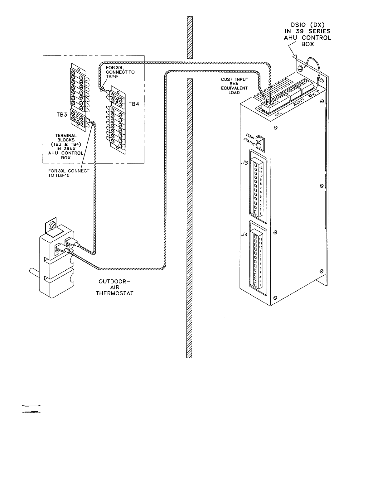
LEGEND
AHU — Air Handling Unit
CUST — Condensing Unit Status
DSIO — Relay Module
DX — Direct Expansion
OAT — Outdoor Air Thermostat
PIC — Product Integrated Control
Factory Wiring
Field Wiring
Fig. 70 — Outdoor Air Thermostat/DSIO Wiring
66
Page 67

Local Interface Device (HSIO) (Fig. 74) — The
HSIO consists of a keyboard with 6 function keys, 5 operative keys, 10 numeric keys (0-9), and an alphanumeric
8-character liquid crystal display (LCD). Key use is explained in Table 10. Each function has one or more subfunctions as shown in Table 11. These functions are described in
greater detail in the Control Operation section of this book.
The HSIO can be factory-or field-installed, and can be remotely mounted if necessary.
Table 10 — Local Interface Device Key Usage
FUNCTION
KEYS
OPERATIVE
KEYS
USE
Status — Display diagnostic codes and current
operating information about the machine
Quick Test — Check inputs and outputs for
proper operation
History — Check latest service dates and
alarms in order of occurrence
Service — Enter specific unit configuration
information
Set Point — Enter operating set points and
day/time/date, holiday, and daylight savings
time information
Schedule — Enter occupied/unoccupied schedules for unit operation
USE
Expand Display — Display a non-abbreviated
expansion of the display
Clear — Clear the screen of all displays
Up Arrow — Return to previous display position
Down Arrow — Advance to next display
position
Enter data
Fig. 72 — Relay Module (DSIO)
Fig. 71 — Processor Module (PSIO Master/Slave)
LID — Local Interface Device
Fig. 73 — Sensor Bus Wiring (Communications)
Fig. 74 — Local Interface Device
67
Page 68

Table 11 — Functions and Subfunctions
SUB-
FUNCTION
NUMBER
1 Current alarms Alarm history Occupied mode
2 Current operating
3 Current operating
4 System inputs — Period 3
5 System outputs — Period 4
6 — — Period 5
7— — Period 6
8— — Period 7
9— — Period 8
10 — — Occupied mode
11 — — Period 1
12 — — Period 2
13 — — Period 3
14 — — Period 4
15 — — Period 5
16 — — Period 6
17 — — Period 7
18 — — Period 8
19 — — — Loadshed
20 — — — Fan tracking
21 — — — Humidity
22 — — — Alarms limits
23 — — — Analog temperature
24 — — — Discrete temperature
25 — — — Service history
26 — — — Service maintenance
27 — — — Timed override
DX — Direct Expansion
Status History Schedule Service Set Point Test
override sched 1
modes
set points
Maintenance
history
— Period 2
Period 1
of schedule 1
of schedule 1
of schedule 1
of schedule 1
of schedule 1
of schedule 1
of schedule 1
of schedule 1
override sched 2
of schedule 2
of schedule 2
of schedule 2
of schedule 2
of schedule 2
of schedule 2
of schedule 2
of schedule 2
FUNCTION
Log on and
Log off
Software
version
Factory
configuration
English/metric
system
User
configuration
Heating coil
configuration
Cooling coil
configuration
DX cooling
configuration
Inlet guide vanes
configuration
Mixed-air damper
configuration
Electric heat
configuration
Nighttime free
cooling configuration
Night purge
configuration
OAVP
configuration
Air quality
configuration 1
Air quality
configuration 2
Optimal start/stop
configuration
Space temperature
reset configuration
configuration
configuration
configuration
configuration
configuration
configuration
configuration
configuration
history
System set points Quick test of
Demand limits Quick test of
Current time Quick test of
Daylight savings
time configuration
Holiday
configuration
——
——
——
——
——
——
——
——
——
——
——
——
——
——
——
——
——
——
——
——
——
——
inputs
outputs
electric heat
Quick test of
DX cooling
Exit quick
test
68
Page 69

CONTROL OPERATION
Accessing Functions and Subfunctions —
See
Table 12. Refer also to Table 11, which shows the 6 functions (identified by name) and the subfunctions (identified
by number). Table13 shows the sequence of all the elements
in a subfunction.
Table 12 — Accessing Functions and Subfunctions
OPERATION KEYBOARD
To access a function, press the subfunction number and the function name key.
The display shows the subfunction group
To move to the other elements, scroll up or down using the arrow keys
When the last element in a subfunction has been displayed, the first element
is repeated
To move to the next subfunction, it is not necessary to use the subfunction
number. Pressing the function name key advances the display through all subfunctions within a function and then back to the first
Display Functions
SUMMARY DISPLAY — Whenever the keyboard has not
been used for 10 minutes, the display automatically switches
to an alternating summary display. This display has 3 parts
(day/time, mode, and alarms), shown below, which alternate
in continuously rotating sequence.
Display Expansion
TUE 12:45 TODAY IS TUE, TIME IS 12:45
MODE 23 UNOCCUPIED HEATING
2 ALARMS THERE ARE 2 ALARMS DETECTED
Return to the previous display at any time by pressing
.
ENTRY
DISPLAY DESCRIPTION
SETPOINT System set points
OHSP X Occupied heating set point
OCSP X Occupied cooling set point
UHSP X Unoccupied heating set point
UCSP X Unoccupied cooling set point
DEMAND Demand limit set points
TIME
DAYLIGHT Daylight savings time
Time of day and day of week
display
To move to another function, either depress the function name key for
the desired function (display shows the first subfunction)
or
Access a particular subfunction by using the subfunction number and the function name key
HOLIDAY Holiday display
SETPOINT System set points
X ALARMS X alarms detected
SETPOINT Current operating set points
69
Page 70
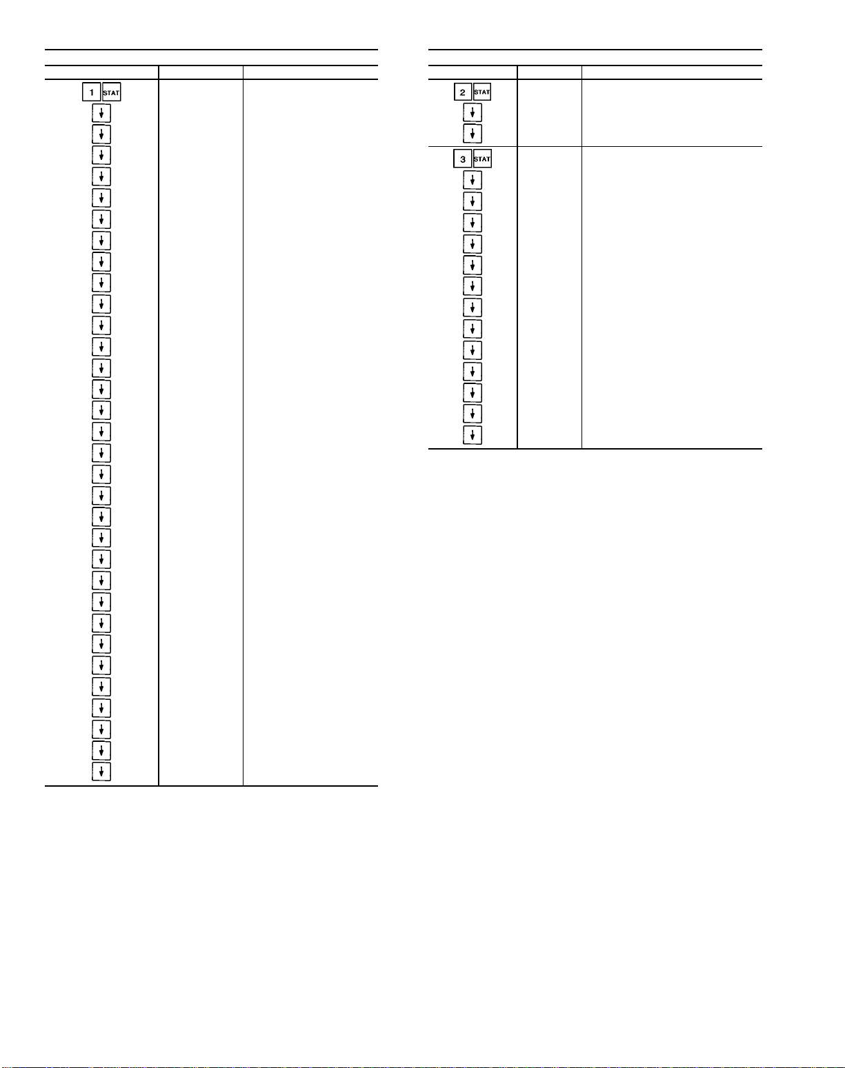
Table 13 — Keyboard Directory
STATUS
Keyboard Entry Display Description
ALARMS Current alarm display
ALARM X 1st alarm
ALARM X 2nd alarm
ALARM X 3rd alarm
ALARM X 4th alarm
ALARM X 5th alarm
ALARM X 6th alarm
ALARM X 7th alarm
ALARM X 8th alarm
ALARM X 9th alarm
ALARM X 10th alarm
ALARM X 11th alarm
ALARM X 12th alarm
ALARM X 13th alarm
ALARM X 14th alarm
ALARM X 15th alarm
ALARM X 16th alarm
ALARM X 17th alarm
ALARM X 18th alarm
ALARM X 19th alarm
ALARM X 20th alarm
ALARM X 21st alarm
ALARM X 22nd alarm
ALARM X 23rd alarm
ALARM X 24th alarm
ALARM X 25th alarm
ALARM X 26th alarm
ALARM X 27th alarm
ALARM X 28th alarm
ALARM X 29th alarm
ALARM X 30th alarm
ALARM X 31st alarm
ALARM X 32nd alarm
STATUS
Keyboard Entry Display Description
MODES Current operating modes
MODE X Mode 1
MODE X Mode 2
SETPOINT Current operating set points
OHSP X Occupied heating set point
OCSP X Occupied cooling set point
UHSP X Unoccupied heating set point
UCSP X Unoccupied cooling set point
SPSP X Static pressure set point
SASP X Supply air set point
CFSP X Delta CFM set point
HUSP X Humidity set point
AOSP X Analog temperature control set point
DOSP X Discrete temperature control set point
Q1SP X Air quality 1 set point
Q2SP X Air quality 2 set point
OASP X
Outdoor air velocity pressure
set point
70
Page 71

Table 13 — Keyboard Directory (cont)
STATUS
Keyboard Entry Display Description
INPUTS System inputs
SPT X Space temperature
SAT X Supply air temperature
RAT X Return air temperature
OAT X Outside air temperature
OAT X Outside air temperature forced
SP X Static pressure
SFS X Supply fan status
ENT X Enthalpy switch status
ENT X Enthalpy switch status forced
RH X Relative humidity
RH X Relative humidity forced
FRZ X Freezestat status
MAT X Mixed air temperature
OARH X Outside air relative humidity
OARH X Outside air relative humidity forced
FLTS X Filter status
FLTS X Filter status forced
TEMP X Temperature input
RVP X Return velocity pressure
SVP X Supply velocity pressure
DHH X Duct high humidity
EVAC X Evacuation
PRES X Pressurization
PURG X Smoke purge
FSD X Fire shutdown
MTR X Meter
OAVP X Outdoor air velocity pressure
OAVP X Outdoor air velocity pressure
AQ1 X Air quality 1
AQ1 X Air quality 1
AQ2 X Air quality 2
AQ2 X Air quality 2
CUST X Condensing unit status
CUST X Condensing unit status
DXSD X DX cooling shutdown
DXSD X DX cooling shutdown
OUTPUTS System outputs
IGV X Inlet guide vanes
DX — Direct Expansion
(x = forced value)
(x = forced value)
(x = forced value)
(x = forced value)
(x = forced value)
(x = forced value)
(x = forced value)
(x = forced value)
(x = forced value)
(x = forced value)
STATUS
Keyboard Entry Display Description
IGV X
MIXD X Mixed air damper
MIXD X
HCV X Heating coil valve
HCV X
CCV X Cooling coil valve
CCV X
SF X Supply fan start/stop
SF X
HIR X Heat interlock relay
HIR X
EHS1 X Electric heat stage 1
EHS2 X Electric heat stage 2
EHS3 X Electric heat stage 3
EHS4 X Electric heat stage 4
EHS5 X Electric heat stage 5
EHS6 X Electric heat stage 6
EHS7 X Electric heat stage 7
EHS8 X
RFVC X Return fan volume
RFVC X
HUM1 X Humidifier first stage
HUM1 X
HUM2 X Humidifier 2nd stage
HUM2 X
AOTC X Analog temperature
AOTC X
DOTC X Discrete temperature
DOTC X
DTCC X Discrete time clock
DTCC X
DXS1 X DX cooling stage 1
DXS2 X DX cooling stage 2
DXS3 X DX cooling stage 3
DXS4 X DX cooling stage 4
DXS5 X DX cooling stage 5
DXS6 X DX cooling stage 6
DXS7 X DX cooling stage 7
DXS8 X DX cooling stage 8
Inlet guide vanes forced
(x = forced value)
Mixed air damper forced
(x = forced value)
Heating coil valve forced
(x = forced value)
Cooling coil valve forced
(x = forced value)
Supply fan start/stop forced
(x = forced value)
Heat interlock relay forced
(x = forced value)
Electric heat stage 8
(NOTE: Only the actual number of
heater stages applicable to the unit
are provided.)
Return fan volume forced
(x = forced value)
Humidifier first stage forced
(x = forced value)
Humidifier 2nd stage forced
(x = forced value)
Analog temperature forced
(x = forced value)
Discrete temperature forced
(x = forced value)
Discrete time clock forced
(x = forced value)
71
Page 72

Table 13 — Keyboard Directory (cont)
SCHEDULE
Keyboard Entry Display Description
OVRD X Number of hours to extend
PERIOD 1 Define period 1 of time
OCC X Start of occupied time
UNO X Start of unoccupied time
MON X Monday flag (x = entry code)
TUE X Tuesday flag (x = entry code)
WED X Wednesday flag (x = entry code)
THU X Thursday flag (x = entry code)
FRI X Friday flag (x = entry code)
SAT X Saturday flag (x = entry code)
SUN X Sunday flag
HOL X Holiday flag
CV — Constant Volume
DX — Direct Expansion
VAV — Variable Air Volume
(same elements as period 1, schedule 1)
(same elements as period 1, schedule 2)
occupied mode of schedule 1
schedule 1
(1 = yes, .0 or CLR = no)
(1 = yes, .0 or CLR = no)
(1 = yes, .0 or CLR = no)
(1 = yes, .0 or CLR = no)
(1 = yes, .0 or CLR = no)
(1 = yes, .0 or CLR = no)
Time periods 2-8 of schedule 1
occupied mode of schedule 2
schedule 2
(1 = yes, .0 or CLR = no)
(1 = yes, .0 or CLR = no)
(1 = yes, .0 or CLR = no)
(1 = yes, .0 or CLR = no)
(1 = yes, .0 or CLR = no)
(1 = yes, .0 or CLR = no)
Time periods 2-8 of schedule 2
SERVICE CONFIGURATIONS
Keyboard Entry Display Description
LOG ON Enter password to log on
LOGGEDON Log on okay
When finished with configuration, log off as follows:
LOGGEDON
LOG OFF
LOGD OFF
VERSION Software version
XXX-XX-X Software version number
FACT CFG Factory configuration
TYPE X Unit type (0 = CV,1=VAV)
COOL X Cooling (0 = none, 1 = coil)
DXST X
HEAT X
EHST X
MIXD X
IAQT X Indoor-air quality type
MATP X Mixed air temperature protection
BUS X
ADR X
PSW X Password XXXX
UNITS X
USER CFG User configuration
NTEN X
HUEN X Humidity configuration
OHEN X Occupied heating configuration
RSEN X
DLEN X Demand limiting configuration
FTEN X Fan tracking configuration
OAEN X Constant outside air
NPEN X Night purge
AQEN X Indoor air quality
IAQP X Indoor air quality priority level
OSEN X Optimal start/stop configuration
TSCH X Timed override schedules
TOVR X Timed override values
HEATCOIL Configuration of heating coil
MPG X Master proportional gain
MIG X Master integral gain
MDG X Master derivative gain
SMG X Submaster gain
SCV X Submaster center value
FOV X Fan off value
SMR X Submaster reference value
SMR X Submaster reference value forced
Shows that configurations are
available
Log off okay; configurations again
password protected
DX cooling stages 0-8
(enter number)
Heating (0 = none,
1 = hot/steam,
2 = electric heat coil)
Electric heat stages 0-8
(enter number)
Mixed air damper (0 = none,
1 = yes, 2 = 2-position)
Bus number (factory default
set=0)
Element address (factory set
default = 1)
English/metric system
(0 = English, 1 = metric)
Nighttime free cooling
configuration
Space temperature reset
configuration
72
Page 73
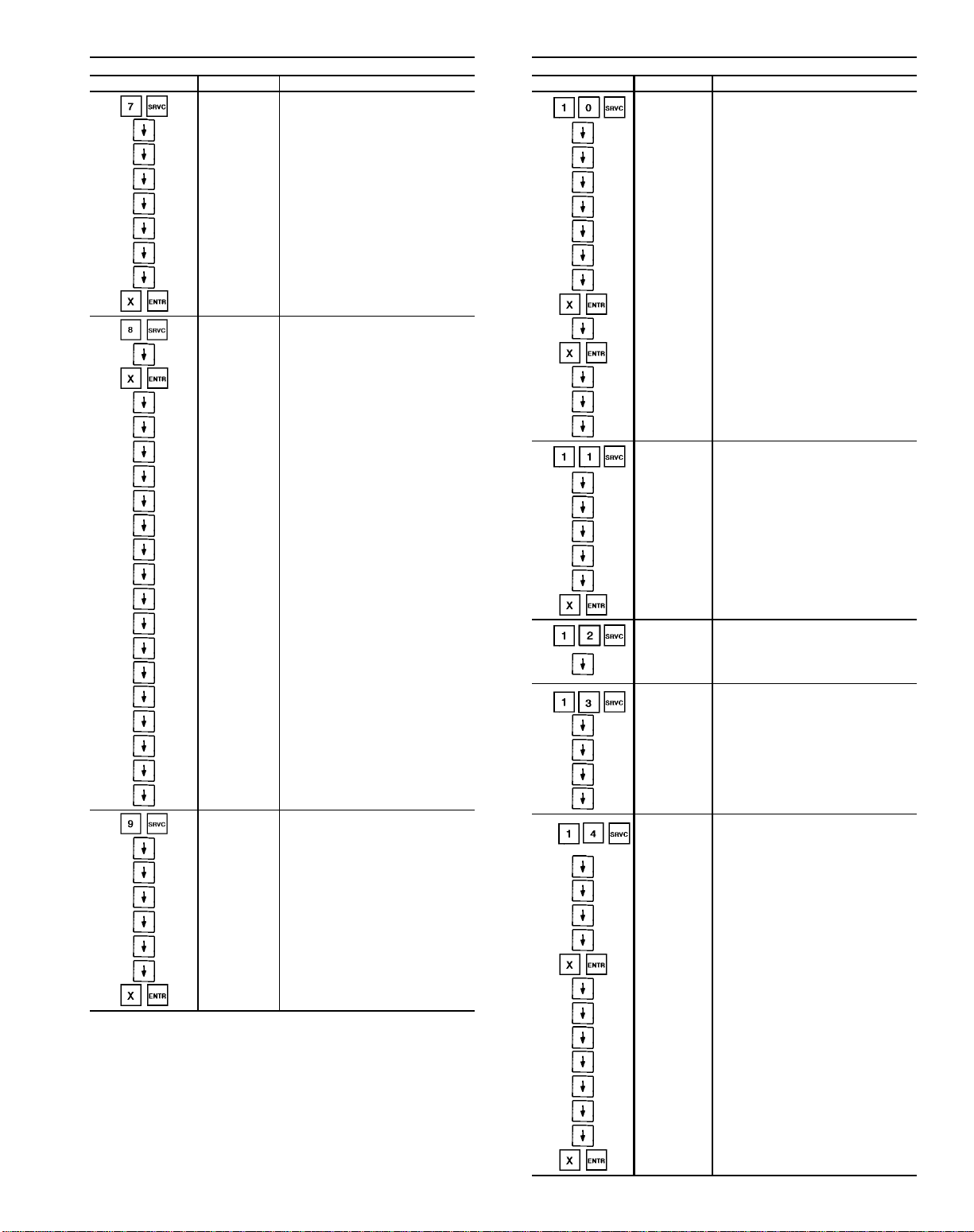
Table 13 — Keyboard Directory (cont)
SERVICE CONFIGURATIONS
Keyboard Entry Display Description
COOLCOIL
MPG X Master proportional gain
MIG X Master integral gain
MDG X Master derivative gain
SMG X Submaster gain
SCV X Submaster center value
HHL X High humidity limit
SMR X Submaster reference value
SMR X Submaster reference value forced
DXCOOL Configure DX cooling
SMG X Submaster gain
SMG X Submaster gain forced
MSR X Minimum submaster reference
DX1G X Stage 1 Time GuardT device
DX2G X Stage 2 Time Guard
DX3G X Stage 3 Time Guard
DX4G X Stage 4 Time Guard
DX5G X Stage 5 Time Guard
DX6G X Stage 6 Time Guard
DX7G X Stage 7 Time Guard
DX8G X Stage 8 Time Guard
DX1T X Stage 1 logic type
DX2T X Stage 2 logic type
DX3T X Stage 3 logic type
DX4T X Stage 4 logic type
DX5T X Stage 5 logic type
DX6T X Stage 6 logic type
DX7T X Stage 7 logic type
DX8T X Stage 8 logic type
INLET GV Configuration of inlet guide vanes
MPG X Master proportional gain
MIG X Master integral gain
MDG X Master derivative gain
SMG X Submaster gain
SCV X Submaster center value
SMR X Submaster reference value
SMR X Submaster reference value forced
DX — Direct Expansion
OAVP — Outside Air Velocity Pressure
Configuration of cooling
(chilled water coil or DX)
SERVICE CONFIGURATIONS
Keyboard Entry Display Description
MIXADMPR Configuration of mixed air damper
MPG X Master proportional gain
MIG X Master integral gain
MDG X Master derivative gain
SMG X Submaster gain
SCV X Submaster center value
MDP X Minimum damper position
SMR X Submaster reference value
SMR X Submaster reference value forced
DPSP X Damper set point
DPSP X Damper set point forced
OAE X Outside air enthalpy
RAE X Return air enthalpy
CNTRL X Damper controlled by
ELECHEAT Configuration of electric heat
MPG X Master proportional gain
MIG X Master integral gain
MDG X Master derivative gain
SMG X Submaster gain
SMR X Submaster reference value
SMR X Submaster reference value forced
NTFC
NTLO X
NPURGE Configuration of night purge
NPMN X Night purge duration
NPDL X
NPDH X
MDP X Minimum damper position
OAC
MPG X Master proportional gain
MIG X Master integral gain
MDG X Master derivative gain
SMG X Submaster gain
SMG X Submaster gain forced
OALV X OAVP sensor low voltage point
OAHV X OAVP sensor high voltage point
OALR X OAVP sensor low voltage reference
OAHR X OAVP sensor high voltage reference
PMF X OAVP sensor probe multiplier factor
MDP X Minimum damper position
SMR X Submaster reference value
SMR X Submaster reference value forced
Configuration of nighttime
free cooling (NTFC)
NTFC lockout temperature (minimum
outside air temperature to operate
NTFC)
Night purge low temperature
damper position
Night purge high temperature
damper position
Configuration of constant
outside air
73
Page 74

Table 13 — Keyboard Directory (cont)
SERVICE CONFIGURATIONS
Keyboard Entry Display Description
AIRQUAL1
MPG X Master proportional gain
MIG X Master integral gain
XDP X Maximum damper position
Q1LV X
Q1HV X
Q1LR X
Q1HR X
MDP X Minimum damper position
AIRQUAL2
MPG X Master proportional gain
MIG X Master integral gain
XDP X Maximum damper position
Q2LV X Air quality sensor 2 low voltage point
Q2HV X Air quality sensor 2 high voltage point
Q2LR X Air quality sensor 2 low voltage reference
Q2HR X Air quality sensor 2 high voltage reference
MDP X Minimum damper position
AOSS X Configuration of optimal start/stop
BLDF X Building factor
UOCF X 24 hour occupied factor
SETB X Set point bias
OSMT X Maximum allowable stop time
SPRESET Configuration of space temperature reset
RTIO X Reset ratio X
LIMT X Reset limit X
LOADSHED Configuration of loadshed
LSGP X Loadshed group number (1-16)
FANTRACK Configuration of fan tracking
SVUL X Supply velocity upper limit
RVUL X Return velocity upper limit
SDAR X Supply duct area
RDAR X Return duct area
MPG X Master proportional gain
MIG X Master integral gain
MDG X Master derivative gain
SMG X Submaster gain
SCV X Submaster center value
SMR X Submaster reference value
SMR X Submaster reference value forced
Configuration of indoor air quality
and AQ sensor no. 1
Air quality sensor 1 low voltage
point
Air quality sensor 1 high voltage
point
Air quality sensor 1 low voltage
reference
Air quality sensor 1 high voltage
reference
Configuration of indoor air quality
and AQ sensor no. 2
SERVICE CONFIGURATIONS
Keyboard Entry Display Description
HUMIDITY Configuration of humidity
MPG X Master proportional gain
MIG X Master integral gain
MDG X Master derivative gain
SMG X Submaster gain
SCV X Submaster center value
SMR X Submaster reference value
SMR X Submaster reference value forced
ALRMLIMT Configuration of alarm limits
SPLO X
SPHO X
SPLU X
SPHU X
SALO X
SAHO X
SALU X
SAHU X
RALO X
RAHO X
RALU X
RAHU X
TLO X
THO X
TLU X
THU X
OATL X Outside air temperature low alarm limit
OATH X Outside air temperature high alarm limit
MATL X Mixed air temperature low alarm limit
MATH X Mixed air temperature high alarm limit
RHL X Relative humidity low alarm limit
RHH X Relative humidity high alarm limit
ORHL X
ORHH X
SPL X Static pressure low alarm limit
SPH X Static pressure high alarm limit
SVPL X Supply velocity pressure low alarm limit
SVPH X Supply velocity pressure high alarm limit
RVPL X Return velocity pressure low alarm limit
RVPH X Return velocity pressure high alarm limit
CFML X Delta CFM x 100 low alarm limit
CFMH X Delta CFM x 100 high alarm limit
Q1H X Air quality sensor 1 high alarm limit
Q2H X Air quality sensor 2 high alarm limit
Space temperature low alarm limit/
occupied
Space temperature high alarm limit/
occupied
Space temperature low alarm limit/
unoccupied
Space temperature high alarm limit/
unoccupied
Supply air temperature low alarm limit/
occupied
Supply air temperature high alarm limit/
occupied
Supply air temperature low alarm limit/
unoccupied
Supply air temperature high alarm limit/
unoccupied
Return air temperature low alarm limit/
occupied
Return air temperature high alarm limit/
occupied
Return air temperature low alarm limit/
unoccupied
Return air temperature high alarm limit/
unoccupied
Temperature input low alarm limit/
occupied
Temperature input high alarm limit/
occupied
Temperature input low alarm limit/
unoccupied
Temperature input high alarm limit/
unoccupied
Outside air relative humidity low alarm
limit
Outside air relative humidity high alarm
limit
74
Page 75

Table 13 — Keyboard Directory (cont)
SERVICE CONFIGURATIONS
Keyboard Entry Display Description
AO CTRL
MPG X Master proportional gain
MIG X Master integral gain
MDG X Master derivative gain
SMG X Submaster gain
SCV X Submaster center value
FOV X Fan off value
SEN X Controlling temperature sensor
SMR X Submaster reference value
SMR X Submaster reference value forced
DO CTRL Configuration of discrete output control
SEN X Controlling temperature sensor
TYP X Discrete output logic type
HYS X Hysteresis
SERVHIST Service history
SDAY X Number of starts in the last 24 hours
STX Total number of starts
FH X Total number of fan run hours
DOW HH:MM Day of week and time of the last Start
DOW HH:MM Day of week and time of the last Stop
SRV/MTN
SMAL X
SMEH X
OVRDHIST History of timed overrides
OHR X Hours of timed overrides
Configuration of analog temperature/
preheat coil control
Configuration of service/maintenance
alarms
Service/maintenance alarm limit
(hours x 1000)
Service/maintenance elapsed hours
(hours x 1000)
SET POINT
Keyboard Entry Display Description
SETPOINT System set points
OHSP X Occupied heating set point
OCSP X Occupied cooling set point
UHSP X Unoccupied heating set point
UCSP X Unoccupied cooling set point
SPSP X Static pressure set point
SASP X Supply air set point
CFSP X Delta CFM set point
HUSP X Humidity set point
AOSP X Analog temperature control set point
DOSP X Discrete temperature control set point
Q1SP X Air quality 1 set point
Q2SP X Air quality 2 set point
OVSP X Outside air velocity pressure set point
DEMAND Demand limit set points
DL1 X Demand limit set point 1
DL2 X Demand limit set point 2
TIME Configuration of current time and date
DAY.HH.MM Current day of the week and time
MM.DD.YY Current date
DAYLIGHT Configuration of daylight savings time
ENM X Daylight savings time starts—month
END X Daylight savings time starts—day
ENT X Daylight savings time starts—time
LVM X Daylight savings time ends—month
LVD X Daylight savings time ends—day
LVT X Daylight savings time ends—time
HOLIDAY Configuration of holidays
MM.DD.DUR
MM.DD.DUR
MM.DD.DUR
MM.DD.DUR
MM.DD.DUR
MM.DD.DUR
MM.DD.DUR
MM.DD.DUR
MM.DD.DUR
MM.DD.DUR
MM.DD.DUR
MM.DD.DUR
MM.DD.DUR
MM.DD.DUR
MM.DD.DUR
MM.DD.DUR
MM.DD.DUR
MM.DD.DUR
Holiday month, day & duration
(days long)
Holiday month, day & duration
(days long)
Holiday month, day & duration
(days long)
Holiday month, day & duration
(days long)
Holiday month, day & duration
(days long)
Holiday month, day & duration
(days long)
Holiday month, day & duration
(days long)
Holiday month, day & duration
(days long)
Holiday month, day & duration
(days long)
Holiday month, day & duration
(days long)
Holiday month, day & duration
(days long)
Holiday month, day & duration
(days long)
Holiday month, day & duration
(days long)
Holiday month, day & duration
(days long)
Holiday month, day & duration
(days long)
Holiday month, day & duration
(days long)
Holiday month, day & duration
(days long)
Holiday month, day & duration
(days long)
75
Page 76
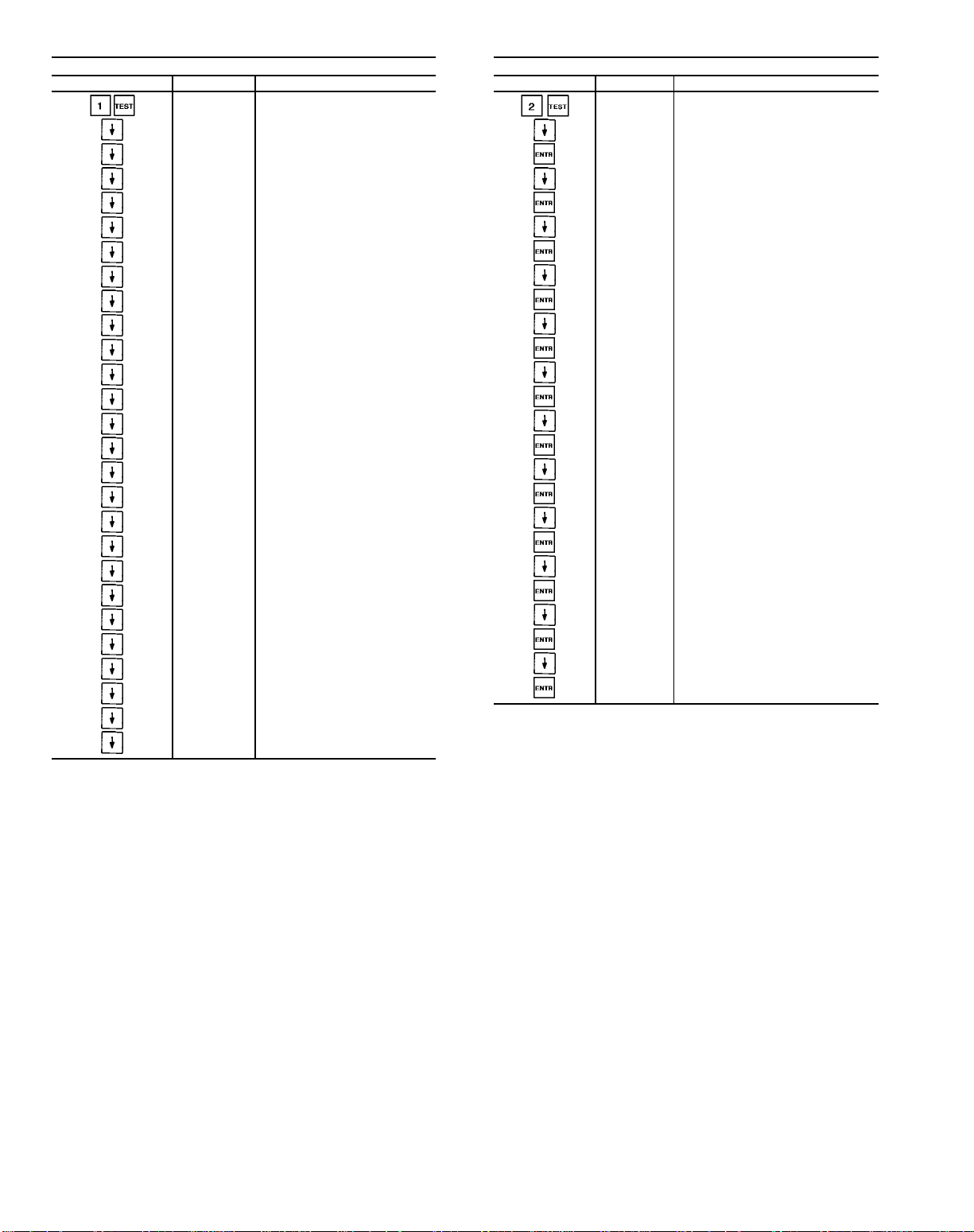
Table 13 — Keyboard Directory (cont)
QUICK TEST
Keyboard Entry Display Description
INPUTS Factory/field test of inputs
SAT X Supply air temperature
OAT X Outside air temperature
SPT X Space temperature
RAT X Return air temperature
ENT X Enthalpy switch status
SFS X Airflow switch status
FRZ X Freezestat
SP X Static pressure
RH X Return air relative humidity
MAT X Mixed air temperature
OARM X Outside air relative humidity
FLTS X Filter status
TEMP X Temperature input
RVP X Return velocity pressure
SVP X Supply velocity pressure
DHH X Duct high humidity
EVAC X Evacuation
PRES X Pressurization
PURG X Smoke purge
FSD X Fire shutdown
MTR X Wattmeter
OAVP X Outside air velocity pressure
AQ1 X Air quality 1
AQ2 X Air quality 2
CUST X Condensing unit status
DXSD X DX cooling shutdown
QUICK TEST
Keyboard Entry Display Description
OUTPUTS Factory/field test of outputs
HCV X Entering heating coil valve test
HCV TEST Testing heating coil valve
CCV X Entering cooling coil valve test
CCV TEST Testing cooling coil valve
MIXD X Entering mixed air damper test
MIXD TEST Testing mixed air dampers
IGV X Entering inlet guide vanes test
IGV TEST Testing inlet guide vanes
SF X Entering supply fan test
FAN TEST Testing supply fan
HIR X Entering heat interlock relay test
HIR TEST Testing heating interlock relay
RFVC X Entering return fan volume test
RFVCTEST Testing return fan volume
HUM1 X Entering humidifer stage 1 test
HUM1TEST Testing humidifer stage 1
HUM2 X Entering humidifier stage 2 test
HUM2TEST Testing humidifier stage 2
AOTC X
AOTCTEST
DOTC X
DOTCTEST
DTCC X
DTCCTEST
Entering analog temperature control
output test
Testing analog temperature control
output
Entering discrete temperature control
output test
Testing discrete temperature control
output
Entering discrete time clock control
output test
Testing discrete time clock control
output
DX — Direct Expansion
76
Page 77

Table 13 — Keyboard Directory (cont)
QUICK TEST
Keyboard Entry Display Description
ELE HEAT Factory/field test of electric heat
EHS1 X Stage 1 test
STG1 TST Testing of electric heat stage 1
EHS2 X Stage 2 test
STG2 TST Testing of electric heat stage 2
EHS3 X Stage 3 test
STG3 TST Testing of electric heat stage 3
EHS4 X Stage 4 test
STG4 TST Testing of electric heat stage 4
EHS5 X Stage 5 test
STG5 TST Testing of electric heat stage 5
EHS6 X Stage 6 test
STG6 TST Testing of electric heat stage 6
EHS7 X Stage 7 test
STG7 TST Testing of electric heat stage 7
EHS8 X Stage 8 test
STG8 TST Testing of electric heat stage 8
HISTORY
Keyboard Entry Display Description
ALARMHST Alarm history
ALARM X Latest alarm
ALARM X Previous alarm
ALARM X Previous alarm
ALARM X Previous alarm
ALARM X Previous alarm
ALARM X Previous alarm
ALARM X Previous alarm
ALARM X Previous alarm
ALARM X Previous alarm
MTMN/HIS Maintenance history
MM.DD.YY Latest service date
DXCOOL Factory/field test of DX cooling
DXS1 X Stage 1 test
STG1TEST Testing DX cooling stage 1
DXS2 X Stage 2 test
STG2TEST Testing DX cooling stage 2
DXS 3 X Stage 3 test
STG3TEST Testing DX cooling stage 3
DXS4 X Stage 4 test
STG4TEST Testing DX cooling stage 4
DXS5 X Stage 5 test
STG5TEST Testing DX cooling stage 5
DXS6 X Stage 6 test
STG6TEST Testing DX cooling stage 6
DXS7 X Stage 7 test
STG7TEST Testing DX cooling stage 7
DXS8 X Stage 8 test
STG8TEST Testing DX cooling stage 8
EXIT TEST Exit quick test
TST CMPL Test completed
DX — Direct Expansion
77
Page 78

STATUS FUNCTION — The status function shows the current status of alarm (diagnostic) codes, operating modes, set
points, all measured system temperatures, output values, and
input values. These subfunctions are defined on
pages 78-80. Refer to Table 11 for additional information.
(Alarms) — Alarms are messages that one or more
faults have been detected. Each fault is assigned a code number which is reported with the alarm. (See Table 14 for
code definitions.) The codes indicate failures that cause the
unit to shut down, terminate an option (such as reset), or
result in the use of a default value as the set point.
Up to 32 alarm codes can be stored at once. To view
them in numerical sequence, press to enter the
alarm display and then press to move to the individual
alarm displays. Press after a code has been displayed
and the meaning of the code will scroll across the screen.
See Example 1.
If an input or output point which has generated an alarm
resets (returns to a range within its limits), the alarm code is
deleted from the list.
A historical sequence of the last 9 alarms can be found
using the key. See Display Functions, History Func-
tion section for more details.
-----------------------------------------------(Modes) — The operating mode codes are dis-
played to indicate the current operating status of the unit.
(See Table 14)
To enter the MODES subfunction, press and use
the key to determine if more than one mode applies.
See Example 2 to read current mode with expansion.
Example 1 — Reading Alarm Codes
KEYBOARD
ENTRY
DISPLAY
RESPONSE
TUE 12:45
MODE 23
3 ALARMS
3 ALARMS 3 alarms detected
ALARM 71 First alarm code
SPACE
TEMPERATURE
LOW LIMIT
ALARM 76 Second alarm code
RETURN AIR
TEMPERATURE
HIGH LIMIT
ALARM 83 Third alarm code
RELATIVE
HUMIDITY
LOW LIMIT
Keyboard has not been used for
at least 10 minutes; alternating
summary display appears on
screen
Explanation of alarm code
Explanation of alarm code
Explanation of alarm code
COMMENTS
The modes are explained below:
Temperature Reset (21) — Indicates that the unit is using
temperature reset to adjust the supply-air set point. The set
point is modified based on space temperature (VAV units
only). Unit must be configured for space temperature
reset ( ). (This mode is enabled by .)
Demand Limit (22) — On CV (constant volume) units, this
mode indicates that the fan is being held off by the Demand Limit option. On VAV units, it indicates that the maximum IGV position is being limited by the Demand Limit
option. Units must be configured for demand limiting
( ). This mode is enabled by , and is only
available on units connected to the Carrier Comfort
Network (CCN).
Unoccupied Heating (23) — Indicates that the space tem-
perature is below the Unoccupied Heating set point and the
unit is on. When the space temperature rises above the set
point the unit is turned off.
Unoccupied Cooling (24) — Indicates that the space temperature is above the Unoccupied Cooling set point and the
unit is on. When the space temperature falls below the set
point the unit is turned off.
Optimal Start (26) — Indicates that the unit is operating
in the Optimal Start mode and is trying to achieve the
Occupied set point. On VAV units this is referred to as morning warm-up. Unit must be configured for optimal start
( ). This mode is enabled by .)
Unoccupied Mode (27) — Indicates that the unit is in the
Unoccupied mode as determined by its time schedule. In this
mode the unit is turned off.
Optimal Stop (29) — Indicates that the unit is being controlled to its expanded Occupied set points. The space temperature is allowed to drift to its expanded Occupied set points
during the last portion of the Occupied period.
Unit must be configured for Optimal Start ( ).
Optimal Stop mode is only applicable to CV units.
Occupied Heating (30) — Indicates that the unit is in the
Heating mode to satisfy its Occupied Heating set point.
Units must be configured for Occupied Heating
().
Occupied Heating is available on VAV units only.
Example 2 — Reading Current Operating Modes
KEYBOARD
ENTRY
DISPLAY
RESPONSE
TUE 12:45
MODE 31
MODE
MODE 31 Mode 31 is in effect
OCCUPIED COOLING Explanation of code 31
COMMENTS
Keyboard has not been
used for at least 10 minutes; alternating summary
display appears on screen.
Modes subfunction of
status function
MODE 22 Mode 22 is in effect
DEMAND LIMIT Explanation of code 22
NOTE: The first mode is the primary operating mode. The second
mode is the secondary operating mode, if applicable.
78
Page 79

Occupied Cooling (31) — Indicates that the unit is in the
Cooling mode to satisfy its Occupied Cooling set point.
Occupied Fan Only (32) — Indicates that the unit is maintaining set point by using a mixture of outside and return air
only. No mechanical heating or cooling is being used.
Nighttime Free Cooling (33) — Indicates that the supply fan
is on and using outside air to precool the space served by the
unit. Unit must be configured for nighttime free cool-
ing ( ). (This mode is enabled by .)
Smoke Pressurization (34) — Indicates that the unit is in the
Pressurization mode. This mode is issued from the fire
system panel. Refer to Table 15 for the state of the items
controlled.
Smoke Evacuation (35) — Indicates that the unit is in the
Smoke Evacuation mode. This mode is issued from the
system panel. Refer to Table 15 for the state of the items
controlled.
Smoke Purge (36) — Indicates that the unit is in the Smoke
Purge mode. This mode is issued from the fire system panel.
Refer to Table 15 for the state of the items controlled.
Fire Shutdown (37) — Indicates that the unit is in the Fire
Shutdown mode. This mode is issued from the fire system
panel or local smoke detector. Refer to Table 15 for the state
of the items controlled.
Quick Test (38) — Indicates that the unit is in the Quick Test
mode. It allows the user to test all inputs and outputs connected to the PIC controller. All control routines are deactivated when the unit is in this mode. This mode can only be
initiated manually when the supply fan status is OFF. (HOA
switch is in OFF position.) In order to reactivate all
the configured control routines, press and then press
.
Timed Override (39) — Indicates that the unit operation has
been extended by the user. Unit must be configured for
TimedOverride schedule and timed override hours ( ).
Table 14 — Display Codes
FORCE STATES
Display Description
1 Fire mode force
2 Internal safety force
3 Quick Test/Service tool force
4 HSIO/Building Supervisor force
5 Remote Building Supervisor force
6 Loadshed minimum offtime force
7 Data transfer force
8 BEST (Building Environmental Systems
Translator) force
9 Temperature override force
10 Loadshed force
OPERATING MODES
Display Description
21 Temperature Reset in effect
22 Demand Limit in effect
23 Unoccupied Heating mode
24 Unoccupied Cooling mode
26 Optimal Start mode
27 Unoccupied mode
29 Optimal Stop mode
30 Occupied Heating mode
31 Occupied Cooling mode
32 Occupied Fan Only mode
33 Nighttime Free Cooling mode
34 Pressurization mode
35 Evacuation mode
36 Smoke Purge mode
37 Fire Shutdown mode
38 Quick Test mode
39 Timed Override mode
ALARMS
Display Description
60 Air quality 1 high limit
61 Air quality 2 high limit
62 Air quality/constant outside air suspended
63 (Not used)
64 DX cooling shutdown
65 Pressurization
66 Evacuation
67 Smoke purge
68 Fire shutdown
69 Service/maintenance required
70 Linkage failure
71 Space temperature low limit
72 Space temperature high limit
73 Supply-air temperature low limit
74 Supply-air temperature high limit
75 Return-air temperature low limit
76 Return-air temperature high limit
77 Mixed-air temperature low limit
78 Mixed-air temperature high limit
79 Outside-air temperature low limit
80 Outside-air temperature high limit
81 Static pressure low limit
82 Static pressure high limit
83 Relative humidity low limit
84 Relative humidity high limit
85 Fan status
86 Freezestat
87 Analog temperature control sensor low limit
88 Analog temperature control sensor high limit
89 Outside-air relative humidity low limit
90 Outside-air relative humidity high limit
91 Supply velocity pressure low limit
92 Supply velocity pressure high limit
93 Return velocity pressure low limit
94 Return velocity pressure high limit
95 Delta CCFM low limit
96 Delta CCFM high limit
97 Filter status
98 Duct high humidity
CCFM — Cfm x 100
79
Page 80

Table 15 — State of Items Controlled
MODE (DISPLAY
CODE)
Pressurization (34) Off On Open Close Close Open to
Purge (36) On On Open Close Open Open to
Evacuation (35) On Off Close Close Open Close Open Off Off
Fire Shutdown (37) Off Off Close Open Close Close Close Off Off
(Set point) — This subfunction displays the current
operating system set points.
To view set points, depress , then use the key
to display the occupied heat set point. Continue to depress
to display all the various system set points. Table 13
shows the order of the various set points.
------------------------------------------------
RETURN
FAN
SUPPLY
FAN
OUTDOOR-
AIR
DAMPER
RETURN-
AIR
DAMPER
EXHAUST
DAMPER
------------------------------------------------
SUPPLY FAN
INLET GUIDE
VANES (IGV)
Static Pressure
Set Point
Static Pressure
Set point
RETURN
FAN IGV
Close On Off
Open to
B D cfm
HEAT
INTERLOCK
RELAY
On Off
ELECTRIC
HEAT ALL
STAGES
(Outputs) — The output subfunction displays or
forces the output value percentage of the inlet guide vanes,
mixed air damper and heating and cooling valves. It also
displays or forces the ON/OFF status of the supply fan and
heat interlock relay,displays the status of electric heat stages,
and displays optional output status for return fan volume control, analog output temperature control, discrete output temperature control, discrete output time clock, and humidifier
(Inputs) — The inputs subfunction displays the read-
ings at the various temperature sensors, fan status, static pressure sensors, enthalpy switch, and freezestat. It also allows
the outside-air temperature sensor, enthalpy switch, returnair relative humidity sensor, outside-air relative humidity sensor, and filter status to be forced to a user deter-
stages.
To read a system output value, enter , then scroll
to the desired output using the key. To force a system
output value, see Example 4. Table 13 shows the order of
the output values.
mined value or status. The forced value overrides the value
that the control system actually reads. This permits operation in the event of a faulty sensor.
To read a sensor, enter , then scroll to the de-
sired sensor reading using the key. To force an input,
see Example 3. Table 13 shows the order of the readouts.
Example 3 — Forcing An Input Value
KEYBOARD
ENTRY
8 0
DISPLAY
RESPONSE
INPUTS System inputs
Scroll past:
SPT X Space temperature
SAT X Supply air temperature
RT X Return air temperature
MAT X Mixed air temperature
OAT 60 Outside air temperature
Outside air temperature value
OAT 80/FORCED
OAT 60
forced to 80. NOTE: Forced
value toggles between value
and word forced
Outside air temperature
forced value removed.
Display no longer flashes
COMMENTS
Example 4 — Forcing An Output Value
KEYBOARD
ENTRY
DISPLAY
RESPONSE
OUTPUTS System Outputs
Scroll past:
IGV X Inlet guide vanes
MIXD X Mixed air damper
HCV X Heating coil valve
CCV X Cooling coil valve
SF OFF Supply fan off
Supply fan forced ON.
SF ON/FORCED
SF OFF
NOTE: Supply fan forced
value toggles between value
(SF ON) and word FORCED
Supply fan forced value removed. Display no longer flashes
COMMENTS
HISTORY FUNCTION
— Displays the 9 latest alarms generated by the
unit in the order of their occurrence. If 9 alarms are displayed, the occurrence of a 10th alarm shifts the first alarm
off the display.
------------------------------------------------
80
Page 81
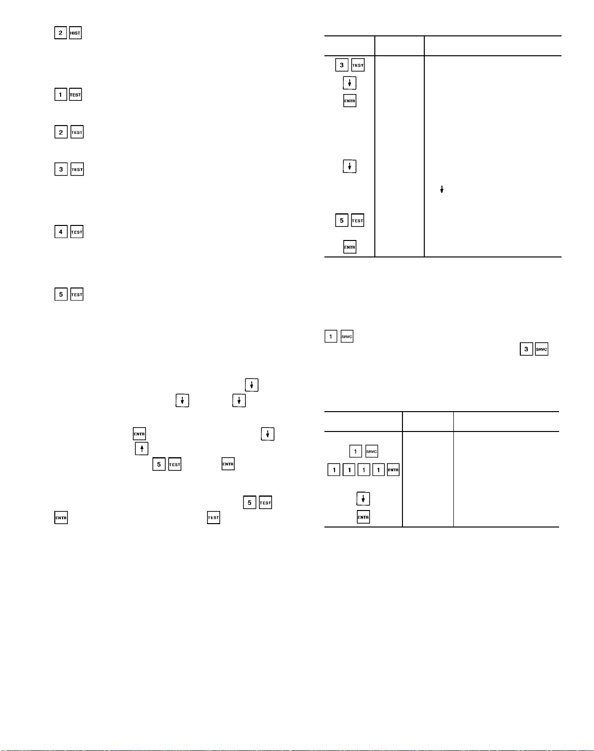
— Displays the latest service date on the local in-
terface device. The last 2 service dates are displayed at the
Building Supervisor.
TEST FUNCTION — The test function operates the Quick
Test diagnostic program.
— Displays the status of all inputs.
-----------------------------------------------— Tests the outputs.
-----------------------------------------------— Tests the electric heaters. Unit must be config-
ured for electric heat to access this subfunction. See
Example 5.
-----------------------------------------------— Tests the stages of direct expansion (DX) cool-
ing. Unit must be configured for DX cooling to access this
subfunction.
-----------------------------------------------— Takes the unit out of Quick Test.
------------------------------------------------
NOTE: The unit must not be operating during the Quick Test
function. Set HOA switch to OFF and follow the test procedure. Set HOA switch to AUTO only as required during
testing.
To reach a particular test, enter its subfunction number
and then scroll to the desired test by pressing . A test
can be terminated by pressing ; pressing after a test
has started terminates the current test and advances the system to the next test. Once in the next step, you may start
the test by pressing , advance past it by pressing , or
back up by pressing . When testing is complete, exit the
Quick Test by pressing and then ; this MUST
be done to restore the unit software to automatic control.
If the keyboard is not used for 10 minutes, the display
returns to the rotating default display. Press and
to exit Quick Test and then press to restart the test
procedure.
Example 5 — Using Quick Test
KEYBOARD
ENTRY
DISPLAY
RESPONSE
ELEC HT
EHS1 Stage 1 test
STG1 TST Pressing ENTR starts the fan test.
EHS2 Pressing the down arrow key
EXIT TST If no other test is desired, exit Quick
TST CMPL
Factory test of electric heat
subfunction of test function
Fan automatically starts. There is an
11-second delay while the inlet
guide vanes open and the heat stage
is enabled. When the electric heat
stage should be running, the display
shows EHS ON. Test remains on
until another key is pressed
advances the system to stage 2 test.
Any stage may be selected. Press
the key until the desired stage is
displayed, then press ENTR to start
the test
Test. Fan shuts off, last electric heat
stage shuts off, and IGVs close
Test is completed. Unit resumes
automatic control
COMMENTS
Programming Functions
SERVICE FUNCTION — The service function allows
the operator to verify or change factory and field configurations. The service subfunctions are listed below. (See
T able13 for details.) Refer to T able16 for configuration value
ranges and defaults.
— Use this subfunction to log on before perform-
ing any subfunction in Factory Configurations ( ),
and to log off after completing service subfunctions. See
Example 6.
Example 6 — Logging On and Logging Off
Service Function
KEYBOARD
ENTRY
TO LOG ON:
TO LOG OFF:
DISPLAY
RESPONSE
LOG ON
LOGGEDON
LOG OFF Ready for operator to log off
LOGD OFF
COMMENTS
Ready for password to be
entered
Operator can now use
service functions
Logged off — password
protection enabled
81
Page 82

Table 16 — Service Configuration Ranges and Defaults
SERVICE
SUBFUNCTION
NUMBER
3
4 English/Metric System (0 = English, 1 = Metric) 0/1 0
5
6
7
8
9
10
11
12 NTFC Lock Out Temperature (F) 40 to 70 50
LEGEND
CV — Constant Volume
DX — Direct Expansion
NTFC — Nighttime Free Cooling
VAV — VariableAir Volume
*Value varies and is automatically calculated by the control. Override this feature by forcing the value.
Unit Type (0 = CV, 1 = VAV) 0/1 0
Cooling Type (0 = none, 1 = chilled water coil,2=DX) 0to2 1
DX Cooling Stages 0 to 8 2
Heating Type (0 = none, 1 = hot water/steam coil,
2 = electric heater)
Electric Heater Stages 0 to 8 0
Mixed Air Dampers (0 = none, 1 = analog,
2 = 2-position)
Indoor-Air Quality Type (1 = single gas, 2 = differen ial/2 gases) 1/2 1
Mixed-Air Temperature Protection Yes/No Yes
Bus Number 0 to 239 0
Element Address 0 to 239 1
Password 0 to 9999 1111
Nighttime Free Cooling Enabled/Disabled Disabled
Humidity Control (0 = none, 1 = analog, 2 = discrete) 0 to 2 0
Occupied Heating Enabled/Disabled Disabled
Space Temperature Reset Enabled/Disabled Disabled
Demand Limit Enabled/Disabled Disabled
Fan Tracking Enabled/Disabled Disabled
Constant Outside Air Enabled/Disabled Disabled
Night Purge Enabled/Disabled Disabled
Indoor Air Quality Enabled/Disabled Disabled
Indoor Air Quality Priority Level (high = 1, low = 2, none = 3) 1 to 3 2
Adaptive Optimal Start/Stop Enabled/Disabled Disabled
Timed Override Schedules 1 to 3 1
(1 = Time schedule no. 1, 2 = Time schedule no. 2, 3 = Both)
Timed Override Hours 0 to 4 0
Heating Coil Master Proportional Gain 0 to 20.0 8 0
Heating Coil Master Integral Gain 0 to 2.0 0 3
Heating Coil Master Derivative Gain 0 to 20.0 0 0
Heating Coil Submaster Gain −20 0 to 20.0 −7.5
Heating Coil Submaster Center Value (%) 0 to 100 50
Heating Coil Fan ‘‘Off’’ Value (F) 35 to 65 40
Cooling Master Proportional Gain 0 to 20.0 8 0
Cooling Master Integral Gain 0 to 2.0 0 3
Cooling Master Derivative Gain 0 to 20.0 0 0
Cooling Coil Submaster Gain −20 0 to 20.0 −7.5
Cooling Coil Submaster Center Value (%) 0 to 100 80
Cooling High Humidity Limit (%) 0 to 99 99
DX Cooling Submaster Gain 2.0 to 25.0 *
DX Cooling Minimum Submaster Reference 0 to 60 40
DX Cooling Stage 1 Time Guard Device (0 = disabled,
1 = enabled)
DX Cooling Stage 2 Time Guard (0 = disabled, 1 = enabled) Enabled/Disabled Enabled
DX Cooling Stage 3 Time Guard (0 = disabled, 1 = enabled) Enabled/Disabled Enabled
DX Cooling Stage 4 Time Guard (0 = disabled, 1 = enabled) Enabled/Disabled Enabled
DX Cooling Stage 5 Time Guard (0 = disabled, 1 = enabled) Enabled/Disabled Enabled
DX Cooling Stage 6 Time Guard (0 = disabled, 1 = enabled) Enabled/Disabled Enabled
DX Cooling Stage 7 Time Guard (0 = disabled, 1 = enabled) Enabled/Disabled Enabled
DX Cooling Stage 8 Time Guard (0 = disabled, 1 = enabled) Enabled/Disabled Enabled
DX Cooling Stage 1 Logic Type (0 = normal, 1 = inverted) Normal/Inverted Normal
DX Cooling Stage 2 Logic Type (0 = normal, 1 = inverted) Normal/Inverted Normal
DX Cooling Stage 3 Logic Type (0 = normal, 1 = inverted) Normal/Inverted Normal
DX Cooling Stage 4 Logic Type (0 = normal, 1 = inverted) Normal/Inverted Normal
DX Cooling Stage 5 Logic Type (0 = normal, 1 = inverted) Normal/Inverted Normal
DX Cooling Stage 6 Logic Type (0 = normal, 1 = inverted) Normal/Inverted Normal
DX Cooling Stage 7 Logic Type (0 = normal, 1 = inverted) Normal/Inverted Normal
DX Cooling Stage 8 Logic Type (0 = normal, 1 = inverted) Normal/Inverted Normal
Inlet Guide Vanes Master Proportional Gain 0 to 5.0 0 5
Inlet Guide Vanes Master Integral Gain 0 to 2.0 0 3
Inlet Guide Vanes Master Derivative Gain 0 to 5.0 0 0
Inlet Guide Vanes Submaster Gain −10.0 to 10.0 5 0
Inlet Guide Vanes Submaster Center Value (%) 0 to 100 50
Mixed-Air Damper Master Proportional Gain 0 to 20.0 8 0
Mixed-Air Damper Master Integral Gain 0 to 2.0 0 3
Mixed-Air Damper Master Derivative Gain 0 to 20.0 0 0
Mixed-Air Damper Submaster Gain −20 0 to 20.0 −7.5
Mixed-Air Damper Submaster Center Value (%) 0 to 100 50
Mixed-Air Damper Minimum Position (%) 0 to 100 10
Electric Heat Master Propor ional Gain 0 to 20.0 8 0
Electric Heat Master Integral Gain 0 to 2.0 0 3
Electric Heat Master Derivative Gain 0 to 20.0 0 0
Electric Heat Submaster Gain 0 to 15.0 5 0
CONFIGURATION VALUE RANGE
FACTORY
DEFAULT
VALUE
0to2 1
0to2 1
Enabled/Disabled Enabled
82
Page 83

Table 16 — Service Configuration Ranges and Defaults (cont)
SERVICE SUBFUNCTION
NUMBER
13
14
15
16
17
18
20
21
22
23
24
26
AOTC — Analog Output Temperature Control
OAVP — Outside Air Velocity Pressure
LEGEND
Night Purge Duration (minutes) 5 to 240 15
Night Purge Low Temperature Damper Position (% output) 0 to 100 10
Night Purge High Temperature Damper Position (% output) 0 to 100 35
Constant Outside Air Master Proportional Gain 0.0 to 5.0 0.3
Constant Outside Air Master Integral Gain 0.0 to 5.0 1.0
Constant Outside Air Master Derivative Gain 0.0 to 5.0 0.0
Constant Outside Air Submaster Gain 60 to 600 *
OAVP Sensor Low Voltage Point 0 to 2 2
OAVP Sensor High Voltage Point 5 to 10 10
OAVP Sensor Low Voltage Reference 0.0 to 2.0 0.0
OAVP Sensor High Voltage Reference 0.01 to 5.00 0.05
OAVP Sensor Probe Mul iplier Factor 0.100 to 9.999 1.564
Air Quality Sensor 1 Master Proportional Gain 0.01 to 1.00 0.10
Air Quality Sensor 1 Master Integral Gain 0.01 to 1.00 0.03
Air Quality Sensor 1 Maximum Damper Position (%) 0 to 100 50
Air Quality Sensor 1 Low Voltage Point 0 to 2 2
Air Quality Sensor 1 High Voltage Point 5 to 10 10
Air Quality Sensor 1 Low Voltage Reference 0 to 2000 0
Air Quality Sensor 1 High Voltage Reference 0 to 2000 2000
Air Quality Sensor 2 Master Proportional Gain 0.01 to 1.00 0.10
Air Quality Sensor 2 Master Integral Gain 0.01 to 1.00 0.03
Air Quality Sensor 2 Maximum Damper Position (%) 0 to 100 50
Air Quality Sensor 2 Low Voltage Point 0 to 2 2
Air Quality Sensor 2 High Voltage Point 5 to 10 10
Air Quality Sensor 2 Low Voltage Reference 0 to 2000 0
Air Quality Sensor 2 High Voltage Reference 0 to 2000 2000
Building Factor (%) 1 to 100 10
24 hour Unoccupied Factor 0 to 99 15
Set Point Bias (F) 0 to 10 2
Maximum Allowable Stop Time 0 to 120 60
Reset Ratio 0 to 10 3
Reset Limit 0 to 20 10
Supply Velocity Upper Limit (in. wg) 0 to 3.0 2.0
Return Velocity Upper Limit (in. wg) 0 to 3.0 2.0
Supply Duct Area 0 to 50 0
Return Duct Area 0 to 50 0
Fan Tracking Master Proportional Gain 0.0 to 2.0 0.5
Fan Tracking Master Integral Gain 0.0 to 2.0 0.5
Fan Tracking Master Derivative Gain 0.0 to 5.0 0.0
Fan Tracking Submaster Gain −20.0 to 20.0 10.0
Fan Tracking Submaster Center Value (%) 0 to 100 50
Humidity Master Proportional Gain 0.0 to 10.0 2.0
Humidity Master Integral Gain 0.0 to 2.0 0.3
Humidity Master Derivative Gain 0.0 to 10.0 0.0
Humidity Submaster Gain −20.0 to 20.0 7.5
Humidity Submaster Center Value (%) 0 to 100 50
Space Temperature Low Alarm Limit — Occupied (F) −10 to 245 65
Space Temperature High Alarm Limit — Occupied (F) −10 to 245 80
Space Temperature Low Alarm Limit — Unoccupied (F) −10 to 245 45
Space Temperature High Alarm Limit — Unoccupied (F) −10 to 245 100
Supply Air Temperature Low Alarm Limit — Occupied (F) −10 to 245 45
Supply Air Temperature High Alarm Limit — Occupied (F) −10 to 245 120
Supply Air Temperature Low Alarm Limit — Unoccupied (F) −10 to 245 35
Supply Air Temperature High Alarm Limit — Unoccupied (F) −10 to 245 180
Return Air Temperature Low Alarm Limit — Occupied (F) −10 to 245 60
Return Air Temperature High Alarm Limit — Occupied (F) −10 to 245 90
Return Air Temperature Low Alarm Limit — Unoccupied (F) −10 to 245 35
Return Air Temperature High Alarm Limit — Unoccupied (F) −10 to 245 120
Temperature Input Low Alarm Limit — Occupied (F) −10 to 245 −10
Temperature Input High Alarm Limit — Occupied (F) −10 to 245 245
Temperature Input Low Alarm Limit — Unoccupied (F) −10 to 245 −10
Temperature Input High Alarm Limit — Unoccupied (F) −10 to 245 245
Outside Air Temperature Low Alarm Limit (F) −40 to 245 −40
Outside Air Temperature High Alarm Limit (F) −40 to 245 120
Mixed Air Temperature Low Alarm Limit (F) 0 to 250 0
Mixed Air Temperature High Alarm Limit (F) 0 to 250 250
Relative Humidity Low Alarm Limit (%) 0 to 100 0
Relative Humidity High Alarm Limit (%) 0 to 100 100
Outside Air Relative Humidity Low Alarm Limit (%) 0 to 100 0
Outside Air Relative Humidity High Alarm Limit (%) 0 to 100 100
Static Pressure Low Alarm Limit (in. wg) 0 to 5.0 1.0
Static Pressure High Alarm Limit (in. wg) 0 to 5.0 2.5
Supply Velocity Low Alarm Limit (in. wg) 0 to 3.0 0.0
Supply Velocity High Alarm Limit (in. wg) 0 to 3.0 3.0
Return Velocity Low Alarm Limit (in. wg) 0 to 3.0 0.0
Return Velocity High Alarm Limit (in. wg) 0 to 3.0 3.0
Delta CFM x 100 (CCFM) Low Alarm Limit 0 to 250 0
Delta CFM x 100 (CCFM) High Alarm Limit 0 to 250 250
Air Quality Sensor 1 High Alarm Limit (ppm) 0 to 2000 800
Air Quality Sensor 2 High Alarm Limit (ppm) 0 to 2000 800
Preheat Coil/AOTC Master Proportional Gain 0.0 to 20.0 5.0
Preheat Coil/AOTC Master Integral Gain 0.0 to 2.0 0.3
Preheat Coil/AOTC Master Derivative Gain 0.0 to 20.0 0.0
Preheat Coil/AOTC Submaster Gain −20.0 to 20.0 −5.0
Preheat Coil/AOTC Submaster Center Value (%) 0 to 100 F 50
Preheat Coil/AOTC Fan/Off Value (F) 35 to 65 40
Preheat Coil/AOTC Sensor 0 to 128 0
Discrete Temperature Control Sensor 0 to 128 0
Discrete Temperature Control Logic 0 to 1 0
Discrete Temperature Control Hysteresis (F) 0 to 20 2
Service/Maintenance Limits (hours x 1000) 0 to 99 0
Service/Maintenance Elapsed Hours (hours x 1000) 0 to 99 0
CONFIGURATION VALUE RANGE
FACTORY DEFAULT
VALUE
83
Page 84

— Used to verify software version.
-----------------------------------------------— Used to verify and change factory configura-
tion. Requires password entry in . See Example 7.
NOTE: When more than one unit is connected to the
Carrier Comfort Network, the element address must be changed
on all but one unit. The element address system default
is 1, and element address numbers cannot be repeated.
Element address must be changed at the local interface
device.
------------------------------------------------
Example 7 — Reading and Changing
Factory Configurations
KEYBOARD
ENTRY
DISPLAY
RESPONSE
FACT CFG
TYPE CV Unit type is constant volume
UNIT TYPE IS CV
TYPE VAV Unit type is changed to VAV
COOL COI Cooling type is coil
DXST 2 DX cooling stage quantity is 2
HEAT HCL
HEAT NON Changed to no heat unit
HEAT ELE Changed to electric heat
HEAT COI
EHST 0 Electric heater stages = 0
EHST N
MIXD ALG Unit with mixed air dampers
MIXD NON Changed to without dampers
IAQT 1
MATP YES
BUS 0 Bus number = 0
ADR 1 Element address = 1
ADR 2 Element address changed to 2
Factory configuration subfunction of service function
Explanation is scrolled across
screen
Heating type is hot water/
steam coil
Heating type is changed back
to hot water/steam coil
Electric heater stages = N,
where N = number of stages
Indoor air quality type
is single gas sensor
Mixed air temperature
protection enabled
COMMENTS
Example 8 — Configuration of Measurements
KEYBOARD
ENTRY
DISPLAY
RESPONSE
UNIT 0
UNIT 1
UNIT 0
COMMENTS
Measurements are displayed using
English (0 = English, 1 = Metric)
Measurements are now displayed
using the Metric system
Measurements are returned to
English
Example 9 — User Configurations
KEYBOARD
ENTRY
DISPLAY
RESPONSE
USER CFG User configurations
NTEN DSB NTFC is disabled
NTEN EN NTFC is enabled
NTEN DSB NTFC is disabled
HUEN 0 Humidifier control is none
HUEN 1
HUEN 0
OHEN DSB
RSEN DSB Space temperature reset (disabled)
DLEN DSB
FTEN DSB Fan tracking (disabled)
OAEN DSB Constant outside air (disabled)
NPEN DSB Night purge (disabled)
AQEN DSB Indoor air quality (disabled)
IAQP DSB
OSEN DSB Optimal start is disabled
OSEN EN Optimal start is enabled
OSEN DSB Optimal start is disabled
TSCH 1 Time schedule No. 1 is enabled
TSCH 2 Time schedule No. 2 is enabled
TSCH 1
TOVR 0 Time override value=0hrs
Unit changed to analog humidifier
control
Humidifier control is changed back
to none
Scroll past occupied heating
(disabled)
Scroll past demand limiting
(disabled)
Indoor air quality priority
level (disabled)
Time schedule is changed back to
No. 2
COMMENTS
PSW XXXX Password
— Used to change the HSIO display of the measure-
ments from English to Metric. See Example 8.
------------------------------------------------
— Used to read or change factory configuration of
user options. See Example 9.
------------------------------------------------
TOVR 1 Time override value=1hr
TOVR 0 Time override value=0hrs
NTFC — Nighttime Free Cooling
84
Page 85
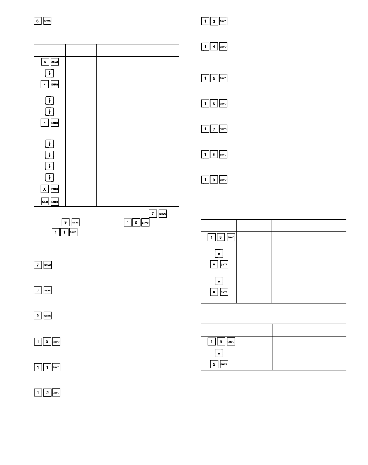
— Used to read or change factory configuration
of heating coil. See Example 10.
Example 10 — Configuration of Heating Coil
KEYBOARD
ENTRY
NOTE: The subfunctions to configure the cooling coil , inlet
guide vanes , mixed air damper , and electric
heaters , are performed in the same manner as
Example 10.
------------------------------------------------
DISPLAY
RESPONSE
HEATCOIL
MPG 8.0 Master proportional gain
MPG N Master proportional gain value is
MIG 0.3 Scroll past master integral gain
MDG 0.0 Master derivative gain
MDG 0.0 Master derivative gain value
SMG −7.5 Submaster gain
SCV 50% Submaster center value
FOV 40 Fan off value
SMR N
SMR X
SMR N
Heat coil field configuration
subfunction of service function
changed to N, where N = new value
within the allowable range
remains 0.0 (old value is still
displayed). N value is not within
the allowable range
Display of submaster reference
value
The submaster reference value
has been forced
The submaster reference value
force has been removed
COMMENTS
— Used to read or change factory configuration of
cooling (chilled water coil or direct expansion).
-----------------------------------------------— Used to read or change configuration of direct
expansion cooling options.
-----------------------------------------------— Used to read or change factory configuration of
inlet guide vanes.
------------------------------------------------
— Used to read or change configuration of
mixed air dampers.
------------------------------------------------
— Used to read or change configuration of elec-
tric heater.
------------------------------------------------
— Used to read or change factory configura-
tion of Nighttime Free Cooling (NTFC) option.
------------------------------------------------
— Used to read or change configuration of
night purge option.
-----------------------------------------------— Used to read or change configuration of
constant outside air option and outside air velocity pressure
sensor.
-----------------------------------------------— Used to read or change configuration of in-
door-air quality option and AQ1 sensor.
-----------------------------------------------— Used to read or change configuration of in-
door-air quality option and AQ2 sensor.
-----------------------------------------------— Used to read or change factory configura-
tion of Adaptive Optimal Start/Stop.
-----------------------------------------------— Used to read or change factory configura-
tion of space temperature reset. See Example 11.
-----------------------------------------------— Used to read or change loadshed group
and number. See Example 12.
------------------------------------------------
Example 11 — Configuration of Space
Temperature Reset
KEYBOARD
ENTRY
DISPLAY
RESPONSE
SPCRESET Space temperature reset field
configuration subfunction of
service function
RTIO 3 Reset ratio set at 3
RTIO N Ratio changed to N, where
N = new value within the
allowable range
LIMT 10 Reset limit set at 10
LIMT N Reset limit changed to N,
where N = new value between
0 and 20
COMMENTS
Example 12 — Configuration of Loadshed
KEYBOARD
ENTRY
DISPLAY
RESPONSE
LOADSHED Loadshed field configuration
subfunction of service function
LSGP 1 Loadshed group 1
LSGP 2 Loadshed group changed to 2
COMMENTS
85
Page 86

— Used to read or change field configuration
of fan tracking. See Example 13.
-----------------------------------------------— Used to read or change factory configura-
tion of humidity control.
-----------------------------------------------— Used to read or change factory configura-
tion of alarm limits. See Example 14.
-----------------------------------------------— Used to read or change field configuration
of analog temperature control. See Example 15.
------------------------------------------------
— Used to read or change field configuration
of discrete temperature control. See Example 16.
------------------------------------------------
Example 13 — Configuration of Fan Tracking
KEYBOARD
ENTRY
DISPLAY
RESPONSE
FANTRACK Fan tracking field configuration
SVUL 1.5
SVUL 2.0
RVUL 1.5
SDAR 0 Supply duct area = 0
SDAR 8 Supply duct area changed to
RDAR 6
MPG 0.5
MIG 0.5
MDG 0.0 Master derivative gain
MDG 4
SMG 10 Scroll past submaster gain
SCV 50
SMR N Submaster reference value
SMR X
SMR N
subfunction of service function
Supply velocity upper limit
= 1.5 in. wg
Supply velocity upper limit
changed to 2.0 in. wg
Scroll past return velocity upper
limit (1.5 in. wg)
8 sq ft. (Enter whole numbers;
decimals not accepted)
Scroll past return duct area
(6 sq ft)
Scroll past master proportional
gain
Scroll past master integral
gain
Master derivative gain
changed to 4
Scroll past submaster
gain center value
(calculated and updated by the
software)
Submaster reference value
forced to X value
Submaster reference value
force is removed
COMMENTS
Example 14 — Configuration of Alarm Limits
KEYBOARD
ENTRY
DISPLAY
RESPONSE
ALRMLIMT
SPLO 65
SPHO 80
SPLU 45
SPHU 100
SALO 45
SALO N Supply-air temperature low limit
Alarm limit field configuration of
subfunction of service function
Scroll past space temperature low
limit (occupied mode)
Scroll past space temperature high
limit (occupied mode)
Scroll past space air temperature
low limit (unoccupied mode)
Scroll past space air temperature
high limit (unoccupied mode)
Supply-air temperature low limit set
at 45 F (occupied mode)
changed to N, whereN=new
value within allowable range
(−10 F to 245 F)
COMMENTS
Example 15 — Configuration of Analog
Temperature Control
KEYBOARD
ENTRY
DISPLAY
RESPONSE
AO CTRL Analog temperature control
MPG 5.0
MIG 0.3 Scroll past master integral gain
MDG 0.0 Scroll past master derivative gain
SMG −5.0 Scroll past submaster gain
SCV 50
FOV 40 Scroll past fan OFF value
SEN 0
SEN 1 Controlling temperature sensor
SMR X Submaster reference value
SMR N
SMR X Force removed from submaster
configuration subfunction of
service function
Scroll past master proportional
gain
Scroll past submaster center
value
Controlling temperature sensor
(none configured)
configured to sensor 1. Sensor
codes as follows:
1 - Supply-air temperature sensor
2 - Outdoor-air temperature
3 - Mixed-air temperature sensor
6 - Space temperature sensor
7 - Return-air temperature sensor
34 - Other optional sensor
Submaster reference value
forced to N value
reference value. Display shows
last value prior to force
COMMENTS
(standard)
sensor (standard)
(optional)
(standard)
(standard)
86
Page 87

Example 16 — Configuration of Discrete
Temperature Control
Example 18 — Service/Maintenance
Alarm Configuration
KEYBOARD
ENTRY
DISPLAY
RESPONSE
DO CTRL Discrete temperature control
SEN 1 Controlling temperature sensor
SEN 34 Controlling temperature sensor is
TYP 0
configuration subfunction of
service function
configured to sensor 1. Sensor
codes as follows:
1 - Supply-air temperature sensor
2 - Outdoor-air temperature
3 - Mixed-air temperature sensor
6 - Space temperature sensor
7 - Return-air temperature
34 - Other optional sensors
34, where sensor 34 is one of
2 optional sensor types
(space temperature sensor or
duct temperature sensor)
Discrete output control logic
(0 = normal logic, 1 = reverse
logic)
COMMENTS
(standard)
sensor (standard)
(optional)
(standard)
(standard)
— Used to read service history. See Example 17.
-----------------------------------------------— Used to read or change field configuration
of service maintenance alarm duration and to read elapsed
time. See Example 18.
-----------------------------------------------— Used to read timed override history. See
Example 19.
NOTE: The key is used to enable or turn on certain
functions; the CLR key is used to disable these functions.
The key may also be used to disable the functions.
SET POINT FUNCTION — Set points are entered through
the keyboard. Set points can be changed within the upper
and lower limits, which are fixed. See Table 17.
Example 17 — Service History Configuration
KEYBOARD
ENTRY
DISPLAY
RESPONSE
SERVHIST
SDAY 2
ST 20
FH 240
4.06.30
4.19.00
COMMENTS
Service history configuration
subfunction of service function
The unit had 2 starts within the
last 24 hours
The unit had a total of 20 starts
since the unit was manufactured
The fan has run for 240 hours
since unit manufacture.
The unit was last started on
Thursday at 6:30 am
The unit was last stopped on
Thursday at 7:00 pm
KEYBOARD
ENTRY
DISPLAY
RESPONSE
SRV/MTN Service/Maintenance alarm
SMAL 2
SMAL 5 Service/Maintenance alarm
SMEH 3 Service/Maintenance elapsed
configuration subfunction of
service function
Service/Maintenance alarm
limit is 2000 hrs (hours x 1000)
limit is changed to 5000 hrs (This
represents the cumulative number
of hours the fan must be energized
before a service/maintenance alarm
is generated)
(NOTE: Entering a . disables the
alarm function)
hours is 3000 (This is the amount of
time elapsed from the start of the
service/maintenance alarm interval)
COMMENTS
Example 19 — Timed Override History
KEYBOARD
ENTRY
DISPLAY
RESPONSE
OVRDHIST
OHR 3 Within the current 24 hour period
Timed override history
subfunction of service function
(beginning at midnight), the unit
operated for 3 hours in the timed
override mode (mode 39)
COMMENTS
— Displays system set points. See Table 13 for
sequence of set points.
-----------------------------------------------— Displays demand limit set points.
-----------------------------------------------— Displays time of day and day of week.
-----------------------------------------------— Displays Daylight Savings Time.
-----------------------------------------------— Displays holidays (month, day, and duration).
Table 17 — Set Point Ranges and Defaults
SET POINT
Occupied Heating Set Point (F) 40 to 90 68
Occupied Cooling Set Point (F) 45 to 99 78
Unoccupied Heating Set Point (F) 40 to 90 55
Unoccupied Cooling Set Point (F) 70 to 99 90
Static Pressure
Set Point (in. wg)
Supply-Air Temperature
Set Point (F)
Delta CFM Set Point 0 to 250 0
Humidity Set Point (%) 0 to 100 40
Analog Temperature
Control Set Point (F)
Discrete Temperature
Control Set Point (F)
Air Quality Sensor 1
Set Point (ppm)
Air Quality Sensor 2
Set Point (ppm)
Outside Air Velocity Pressure
Set Point (in. wg)
ALLOWABLE
RANGE
0 to 5.0 1.5
35 to 65 55
40 to 100 40
−40 to 245 0
0 to 2000 650
0 to 2000 650
0.0 to 5.0 0.08
DEFAULT
87
Page 88

Reading and Changing Set Points — Example 20 shows how
to read and change system set points. Other set points can be
changed by following the same procedure. Refer to
Table 13 for the display sequence of set points in each subfunction.To adjust any parameter after enabling the func-
tion, press until desired parameter is displayed. Key in
new value and press . If input is within the allowable
range, the display shows the parameter and new value. If
the input is not within the allowable range, the old value
remains displayed.
Example 20 — Reading and Changing
System Set Points
KEYBOARD
ENTRY
DISPLAY
RESPONSE
SETPOINT System set points
OHSP 68.0
OHSP 70.0 Key in 70 and press ENTR, display
OCSP 78.0 Present occupied cooling set point
OCSP 78.0 Key in 30 and press ENTR, display
OCSP 75.0 Key in 75 and press ENTR, display
Present occupied heating set point
is 68.0
shows new occupied heating set
point is 70, which is within the
allowable range
is 78.0
still shows occupied cooling set point
as 78.0 because 30 is not within the
allowable range. See Table 15
shows new occupied cooling set
point is 75.0, which is within the
allowable range
COMMENTS
Reading and Changing Time and Date Display — Time is
entered and displayed in 24-hour (military) time. The day of
the week is entered as a number: 1 = MON, 2 = TUE...7 =
SUN. The month is also entered as a number:1=JAN,2=
FEB...12 = DEC. The key is used as the colon when
entering the time and date. See Example 21.
Reading and Changing Daylight Savings Time — Example 22
shows how to read and change daylight savings time. The
month is entered as a number: 1 = January, 2 = February...12
= December. The day of week and time of day are entered
as explained in Reading and Changing Time and Date
Display above.
Example 21 — Setting of Time and Date
KEYBOARD
ENTRY
DISPLAY
RESPONSE
TIME Time display
MON 16:00 Current setting
TUE 13:05 New setting of
JAN 01 96 Current setting
FEB 27 96 New setting of
COMMENTS
subfunction of
set point function
is Monday,
4:00 pm
Tuesday,
1:05 pm is
entered and
displayed
is January 1,
1996
February 27,
1996 is entered
and displayed
Example 22 — Setting Daylight Savings Time
KEYBOARD
ENTRY
DISPLAY
RESPONSE
DAYLIGHT Daylight savings time field
ENM X Month when daylight savings
ENM 4 Daylight savings time
END X Day of month when daylight
END 16 Daylight savings time
ENT X Time of day when daylight
ENT 2.00 Daylight savings time
LVM X Month when daylight savings
LVM 11 Daylight savings time
LVD X Day of month when daylight
LVD 12 Daylight savings time
LVT X Time of day when daylight
LVT 2.00 Daylight savings time
COMMENTS
configuration of set point
function
time begins
configured to start Month 4
(April)
savings time begins
configured to start on the
16th of the month
savings time begins
configured to start at 2:00 am
on the 16th of April
time ends
configured to end Month 11
(November)
savings time ends
configured to end on the 12th
of November
savings time ends
configured to end at 2:00 am
on November 12
88
Page 89

Reading and Changing Holidays — Example 23 explains how
to set holidays. Up to 18 holiday periods can be set for one
calendar year. When the calendar year changes the holidays
must be reconfigured for the new year.
Example 23 — Setting of Holidays
KEYBOARD
ENTRY
DISPLAY
RESPONSE
COMMENTS
HOLIDAY Holiday field config-
uration subfunction
of set point function
NEW
First holiday
configuration
JUL 04 01 The first holiday is
configured to start
Month 7 (July), day 4
(July 4) and last for
one day
NOV 23 02 The second holiday
is configured to start
Month 11 (November), day 23 and last
for 2 days.
SCHEDULE FUNCTION — Two schedules are provided
with the PIC system. Schedule I automatically switches the
unit from an occupied mode to an unoccupied mode. Schedule II automatically changes the optional discrete output from
occupied to unoccupied mode.
Each schedule consists of from one to 8 occupied time
periods, set by the operator.These time periods can be flagged
to be in effect or not in effect on each day of the week. The
day begins at 00.00 and ends at 24.00. The unit is in unoccupied mode unless a scheduled time period is in effect. If
an occupied period is to extend past midnight, it must be
programmed in the following manner: Occupied period must
end at 24:00 hours (midnight); a new occupied period must
be programmed to begin at 00:00 hours on the next day.
The time schedule can be overridden to keep the unit or
optional discrete output in the occupied mode for 1, 2, 3, or
4 hours on a one-time basis.
The air handler can be configured for an applicable holiday/
shutdown schedule. This function can only be used if the
PIC is connected to the Carrier Comfort Network. The network will send a holiday message (flag) to the unit on the
appropriate holiday. The unit then uses the schedule that has
been set for the holiday period. The unit automatically returns to its normal schedule after the holiday period is
complete.
Figure 75 shows a Schedule I example for an officebuilding with the unit operating on a set point schedule. The
schedule is based on building occupancy with 3-hour offpeak cool down period from midnight to 3 am following weekend shutdown. To learn how this sample schedule can be
programmed, see Example 24. The same scheduling procedures can be used to set optional discrete output
Schedule II. Subfunctions through define
schedule of air handler (Schedule I). Subfunctions
through define schedule of optional
discrete output (Schedule II).
Fig. 75 — Schedule I Sample Time Schedule
89
Page 90

Example 24 — Using the Schedule Function
Example 24 — Using the Schedule Function (cont)
KEYBOARD
ENTRY
PROGRAMMING PERIOD 1:
DISPLAY
RESPONSE
PERIOD 1 Define schedule period 1
OCC 00.00 Start of occupied time.
UNO 00.00 Start of unoccupied time
UNO 3.00
MON NO Monday is not flagged
MON YES Monday is now flagged
TUE YES For this example, period 1
TUE NO Tuesday is now flagged
COMMENT
For this example, first
period should start here
(at midnight) so no
entry is needed
(end of period). For this
example, period 1
should end at
3:00 am
Period 1 ends at
3:00 am
for period 1. To put
period 1 into effect on
Monday, Monday must
be flagged yes
for period 1 to be in
effect
is to be in effect on
Monday only. All other
days must be checked
to be sure that they
are flagged no. If any
day is flagged yes,
change to no
no for period 1
KEYBOARD
ENTRY
PROGRAMMING PERIOD 2:
For this example, period 2 is used on Monday and Tuesday.
DISPLAY
RESPONSE
PERIOD 2
OCC 00.00 Start of occupied time
OCC 7.00 Occupied time will
UNO 00.00 Start of unoccupied
UNO 18.00
MON NO Monday is not flagged
MON YES Monday is now flagged
TUE NO Tuesday is not flagged
TUE YES Tuesday is now flagged
WED YES For this example,
WED NO Wednesday is now
COMMENT
Define scheduling
period 2
start at 7:00 am
time (end of period)
for this example,
period 2 should end
at 18:00 (6:00 pm)
Period 2 ends at
18:00 (6:00 pm)
for period 2. To put
period 2 into effect
on Monday, Monday
must be flagged yes
for period 2 to be
in effect
for period 2. To put
period 2 into effect
on Tuesday, Tuesday
must be flagged yes
for period 2 to be
in effect
period 2 is to be in
effect only on
Monday and Tuesday.
All other days must
be checked to be
sure that they are
flagged no. If a day
is flagged yes,
change to no
flagged no for
period 2
90
Page 91
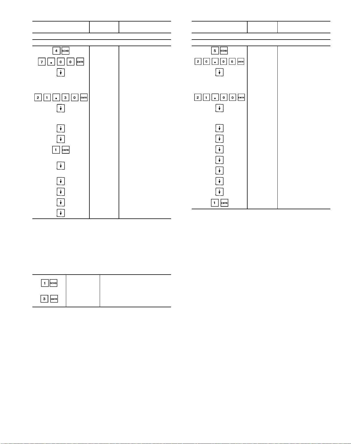
Example 24 — Using the Schedule Function (cont)
Example 24 — Using the Schedule Function (cont)
KEYBOARD
ENTRY
PROGRAMMING PERIOD 3:
For this example, Period 3 is used on Wednesday only.
Period 4 and 5 can be programmed in the same manner, flagging
Thursday and Friday yes for period 4 and Saturday yes for period 5.
For this example, periods 7 and 8 are not used; they should be programmed OCC 00.00, UNO 00.00.
NOTE: When a day is flagged yes for 2 overlapping periods, occupied time will take precedence over unoccupied time. Occupied times
can overlap in the schedule with no consequence.
To extend an occupied mode beyond its normal termination for a
one-time schedule override, program as shown below:
DISPLAY
RESPONSE
OCC 00.00 Start of occupied time
OCC 7.00
UNO 00.00 Start of unoccupied
UNO 21.30
MON NO Check to be sure that
TUE NO
WED NO Wednesday is flagged
WED YES Wednesday is now
THU NO Check to be sure that
FRI NO
SAT NO
SUN NO
HOL NO
COMMENT
Occupied time will start
at 7:00 am
time (end of period 3).
For this example,
period 3 should end at
21:30 (9:30 pm)
Period 3 ends at
21:30 (9:30 pm)
Monday and Tuesday
are flagged no for
period 3
no. Change to yes
flagged yes for
period 3
all other days are
flagged no
KEYBOARD
ENTRY
PROGRAMMING PERIOD 6:
For this example, Period 6 is used for holiday only.
DISPLAY
RESPONSE
OCC 00.00 Start of occupied time
OCC 20.00
UNO 00.00 Start of unoccupied
UNO 21.00
MON NO Check to be sure that
TUE NO
WED NO
THU NO
FRI NO
SAT NO
SUN NO
HOL NO
HOL YES
COMMENT
Occupied time will start
at 20:00 (8:00 pm)
time (end of period 6).
For this example,
period 6 should end at
21:00 (9:00 pm)
Period 6 ends at
21:00 (9:00 pm)
Monday through
Sunday are flagged
no for period 6
Holiday is flagged no.
Change to yes
Holiday is now flagged
yes for period 6
OVRD 0
OVRD 3
Override is set for 0; enter
the number of hours of
override desired
Unit will now remain in
occupied mode for an
additional 3 hours
91
Page 92

CONTROL OPERATING SEQUENCE
Constant Volumeand VariableAirVolumeUnits
TWO-POSITION DAMPER CONTROL — Two-position
damper control opens or closes field-supplied and installed
two-position outdoor-air dampers in order to provide minimum outdoor air ventilation.
If the supply fan is OFF, the damper is closed. If the supply fan is ON, the control determines if the unit is in the
OCCUPIED mode. If unit is in the OCCUPIED mode, the
dampers open. If unit is in the UNOCCUPIED mode, the
dampers close.
FILTERST ATUS CONTROL — This control sequence monitors one or more airflow switches which measure the differential pressure between the upstream and downstream side
of a filter.
When the filter becomes dirty or needs to be replaced, the
airflow switches send a discrete signal to the processor module. This, in turn, generates an alarm at the Local Interface
Device or Building Supervisor.
F ANCONTROL — The supply fan is started or stopped based
on the occupancy schedule, adaptive optimal start, nighttime free cooling, unoccupied heating, unoccupied cooling,
demand limiting, night purge, or timed override.
The start of an occupied period is determined by either
the occupancy schedule or optimal start. If optimal start is
not selected, the supply fan starts at the occupied time entered in the occupancy schedule. If optimal start is selected,
the fan starts at the calculated start time. The fan stops at the
unoccupied time entered in the occupancy schedule. (Timed
override may be used to extend the occupied period between
1 and 4 hours.)
During the unoccupied period, whenever the space temperature falls below the unoccupied heating set point or rises
above the unoccupied cooling set point, the supply fan energizes and runs until the space temperature returns to within
the required limits.
The supply fan can also run between the hours of
3:00 am and 7:00 am when the unit is in the Nighttime Free
Cooling mode to pre-cool the space prior to the Occupied
period.
Constant volume units that are subject to demand limiting
stop the supply fan whenever a loadshed command is received from the CCN Loadshed option. The supply fan remains OFF until the loadshed command is cleared or the internal maximum loadshed timer expires.
NIGHTTIME FREE COOL (NTFC) — Nighttime free cooling is used to start the supply fan to precool the building’s
interior using outside air. This delays the need for mechanical cooling when the system enters the Occupied mode.
The system determines if the outside conditions (temperature and enthalpy) are suitable for outside cooling. If so, the
supply fan is energized and the dampers modulate open. Once
the space has been sufficiently cooled, the fan stops.
If the outside air conditions are not suitable, the fan
remains OFF.
The unit must have mixed-air dampers to operate NTFC.
NTFC is scheduled to run only between the hours of
3:00 am and 7:00 am.
NIGHT PURGE — During the unoccupied period, this fea-
ture starts the fans and opens the mixed-air dampers to remove stagnant air and airborne pollutants from the building
space.
If the current time is within the configured night purge
duration, the control reads the outdoor air temperature and
determines the mixed-air damper position. If the outdoor air
temperature is less than the configured NTFC lockout temperature, the system sets the mixed-air dampers at the configured low temperature position. If the outdoor-airtemperature
is greater than the NTFC set point, or the enthalpy is high,
the system sets the dampers at the configured high temperature position.
When the outside-air temperature is below the NTFC set
point and the low temperature night purge damper position
is set to zero, night purge is not performed. Also, when the
outside air temperature is above the NTFC set point and enthalpy is high, if the high temperature night purge damper
position is set to zero, night purge is not performed.
Night purge ends when the occupied time period begins.
QUICK TEST — The Quick Test is initiated and controlled
at the local interface device (HSIO). It allows the service
person or building owner to test all inputs and outputs of the
PIC controls. When used, it displays all current values of
input channels and allows the user to exercise all output
channels.
Quick test suspends all process algorithms and forces all
outputs with a service priority.
All service forces are removed when Quick Test is exited
and control is returned to the process algorithms.
ANALOG OUTPUT TEMPERATURE CONTROL/
PREHEAT COIL CONTROL — The analog output temperature control adjusts an analog output to a fixed set point,
based on any analog temperature sensor connected to the unit.
(Applicable sensors are: space temperature sensor, outsideair temperature sensor,mixed-air temperature sensor,supplyair temperature sensor, and return-air temperature sensor.)
If the fan is ON, the control identifies the controlling temperature sensor, reads the sensor and compares the temperature to the configurable set point. It then calculates the temperature required to satisfy the conditions.
The calculated value is compared to the actual temperature and the corresponding output is modulated to the
required position.
The preheat coil control adjusts the steam or hot water
valve. The valve is modulated to raise the temperature of
incoming outside air. The control uses a sensor downstream
from the preheat coil to monitor the air temperature.
If the supply fan is OFF, the heating valve is modulated
to maintain the desired minimum duct temperature (fan off
value).
If the supply fan is on and the entering-air temperature is
below the set point value, the heating valve is modulated to
obtain the desired leaving-air temperature.
92
Page 93

DISCRETE OUTPUT/ANALOG INPUTCONTROL— The
discrete output is controlled as a function of a temperature
sensor connected to the 39L or 39NX unit. (Applicable sensors are: space temperature sensor, outside-air temperature
sensor, mixed-air temperature sensor, supply-air temperature sensor, and return-air temperature sensor.) The discrete
output is turned ON/OFF as required to maintain the user
configured set point.
The controlling sensor is identified and its value is read.
The control determines which user-configurable control logic
(normal or reverse) is required.
The control compares the sensor value to the configured
set point.
If normal logic is used, the discrete output is turned ON
when the sensor value is equal to or greater than the set point.
This output is turned OFF when the sensor value is less than
the set point decreased by a user configurable hysteresis.
If reverse logic is used, the discrete output is turned ON
whenever the sensor value is less than the set point. This
output is turned OFF when the sensor value is greater than
the set point increased by a user configurable hysteresis.
DISCRETE OUTPUT, TIMECLOCK CONTROL — This
control sequence turns ON an output channel when the current time of day is greater than or equal to the Occupied time
and less than the next Unoccupied time. This discrete output
is OFF at all other times. The output can be used for lighting
control, pump control, or to control other devices which have
to be ON during the Occupied period and OFF during the
Unoccupied period. This control sequence operates under its
own time schedule (Schedule II).
Using the local interface device or building supervisor,the
output may be overridden to extend the occupied period between 1 and 4 hours.
The control determines the output that is under timeclock control. The current time of day is compared to the
Occupied time and to the next Unoccupied time. If the
current time of day is equal to or within the Occupied time
period, the discrete output is turned ON. If the current time
of day is equal to or within the Unoccupied time period, the
discrete output is turned OFF.
HUMIDITY (ANALOG OUTPUT) CONTROL — The humidity analog output control adjusts the steam valve of the
steam grid humidifier. The valve is modulated to maintain
the desired space or desired return-air humidity set point,
depending on whether a wall-mounted or duct-mounted humidity sensor is used. A duct high humidity switch is also
monitored and provides a user adjustable high limit safety.
If the supply fan is OFF, the steam valve is held closed.
If the supply fan is ON, and the unit is in the Unoccupied
mode, the valve is held closed.
If the supply fan is ON and the unit is in the Occupied
mode, the system determines the status of the duct high humidity switch. If the duct humidity is above the switch set
point, the valve is held closed. If the duct humidity is less
than the switch set point, the control reads the humidity sensor, compares the value to the set point and modulates the
output as required to satisfy conditions.
HUMIDITY(DISCRETE OUTPUT) CONTROL — The humidity control sequentially adjusts a 2-stage humidifier.The
humidifier is controlled to maintain a desired space or returnair humidity, depending on whether a wall-mounted or ductmounted humidity transmitter is used.
The first stage of humidification energizes the humidifier
spray pump (if applicable) along with the first stage of the
humidifier.The second stage of humidification energizes the
second stage of the humidifier.
A duct high humidity switch is also monitored and provides a user adjustable duct high humidity limit safety.
If the fan status is ON and the unit is in the Occupied
mode, the control reads the space or return-air humidity sensor. If the humidity is 2% less than the humidity set point,
the first stage is turned ON.
If the humidity is 5% less than the humidity set point, both
stages are turned ON.
As the humidity increases, the stages are turned OFF as
follows: When the humidity is within 2% of the set point,
the second stage of the humidifier is turned OFF. When the
humidity is greater than or equal to the set point, both stages
are turned OFF. If the high humidity switch is tripped, all
stages of the humidifier are turned OFF.
93
Page 94

INDOOR-AIR QUALITY (IAQ) — This function maintains the correct occupied ventilation rate using CO2as an
indicator of occupancy level or controls the levels of volatile
organic compounds (VOCs) or other indoor air pollutants by
modulating the mixed air dampers. Varyingquantities of outdoor air are admitted during the Occupied period to maintain the ventilation rate at its set point or pollutants at or
below the configured set points of the air-quality (AQ) sensors. See Fig. 76.
sensors are available from the factory as options for
CO
2
field installation. VOC or other types of sensors can be fieldsupplied and installed. Sensors used with the IAQ feature
can be configured several different ways:
• One sensor can be installed in either the space or return air
stream to continuously monitor a single gas.
• Two sensors (monitoring the same gas) can be installed in
different locations to provide separate inputs. For example, one sensor can be located in an occupied space and
another in the return air duct, or each sensor can be installed in a different occupied space.
• Two sensors (typically VOC sensors monitoring the same
gas) can be installed inside and outside the occupied space
for comparative measurements. The control is configured
to modify the damper position based on the value of the
sensor in the occupied space, but before admitting outside
air, the control performs a differential check to determine
if the value of the sensor measuring the outside air is higher.
If the outside sensor has a higher value, the damper does
not change position.
Systems with One AQ Sensor — During the unoccupied
period, the minimum damper position maintained by the
IAQ control is 0. During the occupied period, the control
reads the AQ1 sensor input and compares it to the configured set point. The control then calculates the minimum damper
position to maintain the set point. If no other control is attempting to adjust the dampers to a more fully open position
than the IAQ control, the damper is adjusted to the position
determined by the IAQ control. Otherwise, the damper is
positioned by the superseding control routine or at its configured minimum position.
Systems with TwoAQ Sensors (Separate Readings) — The
preceding sequence for the AQ1 sensor also applies to the
AQ2 sensor, but the damper position is determined by either
the AQ1 or the AQ2 sensor according to which sensor value
demands the more fully open damper position.
Systems with TwoAQ Sensors (Differential Check) — If differential sensing is configured for two VOC sensors, the control reads the AQ2 (outside air) sensor to determine if its
value is greater or less than that of the AQ1 (indoor air) sensor. If the AQ2 value is greater than the value of the AQ1
sensor, the mixed-air damper position is set to 0. If the AQ2
value is less than the AQ1 value (by at least 1% of the configured minimum sensor value), the control uses the AQ1
value to modulate the dampers and maintain the AQ set point.
IAQ System Protection — To protect the system against coil
freeze-up in cold climates or high heat and humidity in warm
climates, the system provides several user-selectable features to override or modify the IAQ functions. An adjustable
maximum position for the mixed-air damper is provided for
each AQ sensor, and a selection is available to maintain the
minimum mixed-air temperature at approximately 45 F.Space
temperature and humidity protection can temporarily suspend IAQ functions until the temperature and humidity conditions return to the desired set points. On VAV systems during cooling, the IAQ function can be limited to maintain the
required supply-air temperature.
94
Page 95

Fig. 76 — Indoor-Air Quality (IAQ) Control Operation
95
LEGEND
AQ — Air Quality Sensor
IAQ — Indoor-Air Quality
MAT — Mixed-Air Temperature
OAT — Outdoor-Air Temperature
RH — Relative Humidity
SAT — Supply-Air Temperature
SPT — Space Temperature
VAV — Variable Air Volume
Page 96

SMOKE CONTROL — When the 39L or 39NX unit is
equipped with an optional smoke control and a fire system
is installed, 4 modes are provided to control smoke within
areas serviced by the air-handling unit. Each mode must be
energized individually from the approved building fire alarm
system, and the corresponding alarm is then generated at the
local interface device or Building Supervisor.
The system must include a separate return fan and an ex-
haust air damper witha4to20mAactuator.
The building fire alarm system must provide 4 normallyopen dry contact closures and a double-pole, double-throw
(DPDT) relay (24 vac coil, contacts rated 10 amps at
240 vac) for the Fire Shutdown mode.
Fire Shutdown Mode — The fire alarm system must provide
a normally-open dry contact closure which, when activated,
energizes the Fire Shutdown mode.
When the Fire Shutdown mode is energized, the supply
and return fans stop, the outside and exhaust air dampers
close, and the return-air dampers open.
This mode remains in effect as long as the input signal is
maintained at the fire system panel. An alarm is generated
from this input and sent to the Building Supervisor. In order
for this mode to be initiated, the input signal must be maintained for no less than 2 seconds.
Evacuation Mode — The building fire alarm system must provide a normally-open dry contact closure which, when activated, energizes the Evacuation mode. When the
Evacuation mode is energized, the supply fan shuts down,
the return fan starts, the outside-air and return-air dampers
close, and the exhaust air dampers open.
This mode remains in effect for as long as the input signal
is maintained at the fire system panel. An alarm is generated
from this input and sent to the Building Supervisor. In order
for this mode to be initiated, the input signal must be maintained for no less than 2 seconds.
Pressurization Mode — The building fire alarm system must
provide a normally-open dry contact closure which, when
activated, energizes the Pressurization mode. When the
Pressurization mode is energized, the supply fan starts, the
return fan shuts down, the outside dampers open, and the
exhaust and return-air dampers close.
This mode remains in effect as long as the input signal is
maintained at the fire system panel. An alarm is generated
from this input and sent to the Building Supervisor. In order
for this mode to be initiated, the input signal must be maintained for no less than 2 seconds.
Smoke Purge Mode — The building fire alarm system must
provide a normally-open dry contact closure which, when
activated, energizes the smoke purge mode.
When the smoke purge mode is energized, the supply fan
starts, the return fan starts, the outside air and exhaust air
dampers open and the return-air dampers close.
This mode remains in effect as long as the input signal is
maintained at the fire system panel. An alarm is generated
from this input and sent to the Building Supervisor. In order
for this mode to be initiated, the input signal must be maintained for no less than 2 seconds.
ADAPTIVE OPTIMAL START — Optimal Start is used to
heat up or cool down the space prior to occupancy. The purpose is to have the space temperature approach and then achieve
the occupied set point by time of occupancy. The control
uses outdoor-air temperature, space temperature, occupied
set point, and a ‘K’ factor in minutes/degrees to calculate a
start time offset, which is the time in minutes that the system
should be started in advance of the occupied time. The control monitors its results and adjusts the K factor to assure
that the Occupied set point is achieved at time of occupancy.
Constant Volume Units Only
HEATINGCOILCONTROL — The heating coil control adjusts the steam or hot water valve. The valve is modulated
to prevent the space temperature from falling below the desired set point.
If the supply fan is OFF, the heating valve is modulated
to maintain a desired minimum duct temperature (fan off value).
If the fan is ON, the system reads the space sensor and
computes the supply-air temperature required to satisfy
conditions.
Once the required supply-air temperature has been
calculated, it is compared to the actual supply-air temperature and the heating coil valve modulates to the required
position.
CHILLED WATER COIL COOLING CONTROL — The
cooling coil control adjusts the chilled water valve. The valve
is modulated to prevent space temperature from exceeding
the desired set point. The valve holds its normal position if
the space temperature is below the set point or the supply
fan is OFF.
If the fan is ON, the control reads the humidity sensor
(if supplied) and compares the value to the high humidity
limit.
If the humidity is higher than the high humidity limit, the
chilled water valve fully opens.
If the humidity is below the high humidity limit, the control reads the space temperature sensor and computes the supplyair temperature required to satisfy conditions.
Once the required supply-air temperature has been calculated, it is compared to the actual supply-air temperature
and the chilled water valve modulates to the position required to maintain desired conditions.
See Fig. 77 for cooling coil operation flow chart.
DIRECT EXPANSION COOLING CONTROL — The
direct expansion (DX) cooling control regulates the DX cooling system. The DX cooling stages are energized and deenergized to prevent the space temperature from exceeding the
desired set point. The stages remain off if the space temperature is below the set point or the supply fan is OFF.
If the supply fan is ON, the control reads the humidity
sensor (if supplied) and compares the value to the high
humidity limit. If the humidity is higher than the high humidity limit, the DX cooling stages are energized to maintain a minimum supply-air temperature. If the humidity is
below the limit, the control reads the space temperature sensor and computes the supply-air temperature required to satisfy conditions.
Once the required supply-air temperature has been calculated, it is compared to the actual supply-air temperature
and the required DX cooling stages are energized to maintain the desired conditions.
See Fig. 77 for cooling operation and Fig. 78 for DX submaster gain operation. For more complete information, refer
to the Application Data book for Product Integrated Controls with DX Cooling.
96
Page 97

Fig. 77 — Cooling (DX and Chilled Water) Control Operation
97
LEGEND
CCV — Cooling Coil Valve
CV — Constant Volume
DX — Direct Expansion
RAT — Return-Air
Temperature
RH — Relative Humidity
Page 98

DX — Direct Expansion
MAT — Mixed-Air Temperature
RAT — Return-Air Temperature
SAT — Supply-Air Temperature
Fig. 78 — DX Submaster Gain Control Operation
98
LEGEND
Page 99

MIXED-AIR DAMPER CONTROL — The mixed-air damper
control adjusts modulating outside-air, return-air,and exhaustair dampers. When outside air conditions are unsuitable for
atmospheric cooling, the dampers are held to an adjustable
minimum outside air position. When outside air conditions
are suitable for atmospheric cooling, the mixed-air dampers
are modulated to maintain a space temperature that is between the heating and cooling set points in an effort to minimize the need for heating or mechanical cooling. The damper
set point is automatically adjusted as a function of outdoorair temperature or can be set to a fixed value by the user.
If the supply fan is OFF, the mixed-air dampers are kept
closed to outside air and open to return air.
If the fan is ON, the system checks to see if the system is
in the HEATmode. If system is in the HEATmode, the mixedair dampers are held in the minimum position.
If the system is not in the HEAT mode, it determines if the
outside conditions are suitable for atmospheric cooling. The
control compares the outdoor-air temperature to the space
temperature. If the outdoor-air temperature is less than the
space temperature, the system does either an enthalpy check
(using an outside-air enthalpy switch) or a differential enthalpy check. (Return-air temperature is compared to returnair relative humidity for return-air differential enthalpy.Outsideair temperature is compared to outside-air relative humidity
for outside-air differential enthalpy.)
The control then determines if the outdoor-air temperature is below the Nighttime Free Cool Lockout (NTLO). If
so, the damper set point is changed to 1.0 degree less than
the Occupied Cooling set point, allowing the system to use
return air during the heating mode.
If the outdoor-air temperature is higher than 68 F, the control sets the damper set point to 1.0 degree higher than the
Occupied Heating set point to provide cooling, allowing the
system to use outside air.
If the outdoor-air temperature is higher than NTLO but
less than 68 F, the system sets the damper set point halfway
between the Occupied Heating and Occupied Cooling set points
to provide ventilation.
If outside conditions are suitable, the control compares the
space temperature to the damper set point and computes the
supply-air temperature required to satisfy conditions.
Once the required supply-air temperature has been calculated, it is compared to the mixed-air temperature sensor
value (if installed), otherwise the supply-air temperature sensor determines the damper position. The damper adjustment
rate is limited to 5% per minute if the outside-air temperature is less than 40 F. This rate limit prevents nuisance low
temperature thermostat tripping.
ELECTRIC HEATER CONTROL — Electric heater staging regulates the electric heater. The heater is staged to prevent the space temperature from falling below the desired
set point. (The number of heat stages is factory set for each
unit’s heater.)
If the supply fan is OFF, all stages of electric heat are
turned off.
If the fan is ON, the control reads the space temperature
sensor and calculates the supply-air temperature required to
satisfy conditions.
Once the required supply-air temperature has been calculated, it is compared to the actual supply-air temperature
to determine the number of heat stages required to satisfy
conditions. The required stages are energized one at a time,
with 2-second intervals between stages.
ADAPTIVE OPTIMALSTOP—Optimal stop allows the space
temperature to drift to an expanded occupied set point during the last portion of an occupied period. The control calculates a stop time offset, which is the time in minutes prior
to the scheduled unoccupied time, during which expanded
set points can be used. Adaptive optimal stop utilizes space
temperature, an expanded Occupied set point, and a K factor
to calculate stop time offset. The amount to expand the Occupied set point is user configurable. Like adaptive optimal
start, the control corrects itself for optimal operation by adjusting the K factor.
TWO-STEP DEMAND LIMITING (Available on Units
Connected to the Carrier Comfort Network Only) — If the
Demand Limit option is enabled, the control receives and
accepts redline alert and loadshed commands from the
Network Loadshed option. See the CCN Loadshed manual
for additional information.
When a redline alert is received, the Control decreases the
Occupied Heating set point by 2° F and increases the Occupied cooling set point by 2° F.
When a loadshed command is received, the supply fan turns
OFF.
The maximum loadshed timer prevents the system from
remaining in loadshed, should the control lose communications with the Loadshed option. If the timer expires before the loadshed command is cleared by the Loadshed option, the control clears the loadshed command itself and
returns to normal control. The loadshed timer is factory set
at 60 minutes.
Variable Air Volume Units Only
CONSTANT OUTSIDE AIR (OAC) — During Occupied
periods, this feature provides a continuous flow of outside
air into the building. The OAC control modulates the mixedair damper to a configurable minimum open position to ensure outside air is admitted. During Unoccupied periods, the
control signals the dampers to fully close.
To monitor the outside airflow during Occupied periods,
the OAC control reads the outside-air velocity pressure (OA VP)
sensor, compares its value to the OAVP set point, and adjusts the mixed-air dampers to the position required to achieve
the configured velocity pressure.
If a control routine (other than OAC) or the configured
minimum damper position require the dampers to be more
fully open than the OAC setting, that routine or position overrides the OAC control. To protect against coil freeze-up in
colder climates, the PIC provides selectable low temperature protection to limit the minimum mixed-air temperature
to approximately 45 F.
See Fig. 79 for OAC control flowchart.
99
Page 100

HEATINGCOILCONTROL — The heating coil control adjusts the steam or hot water valve. Heat is primarily used for
morning warm-up or Occupied Heating with the valve modulated to maintain desired return-air temperature.
If the supply fan is OFF, the heating valve is modulated
to maintain a desired minimum duct temperature (fan off value).
If the fan is ON, the system determines if it is in the morning warm-up mode. If it is, the return-air sensor is read and
compared to the Occupied Heating set point. If heating is
required, the control calculates the supply-air temperature
required to satisfy conditions.
Once the required supply-air temperature has been calculated, it is compared to the actual supply-air temperature
and the heating coil valve modulates to the required
position.
The heat interlock relay is energized whenever there is a
need for heat.
Once morning warm-up is completed, heat is activated again
unless Occupied Heat has been selected.
During cooling or fan-only operation, heat can also be provided to maintain the supply-air temperature when the amount
of cold outside air admitted by the IAQ or OAC controls
causes the temperature to fall below the supply-air set point.
CHILLED WATER COIL COOLING CONTROL — The
cooling coil control adjusts the chilled water valve. The valve
is modulated to maintain desired supply-air temperature set
point. The valve is held in its normal position whenever the
system is in Nighttime Free Cooling or whenever the supply
fan is OFF.
If the fan is ON, the control reads the humidity sensor and
compares the value to the high humidity limit.
If the humidity is higher than the humidity limit, the chilled
water valve fully opens.
If the humidity is below the high humidity limit, or if no
humidity sensor is supplied, the control reads the supply-air
sensor and computes the supply-air temperature required to
satisfy conditions, provided that return-air temperature is greater
than the Occupied Cooling set point.
Once the required supply-air temperature has been calculated, it is compared to the current supply-air temperature
and the chilled water valve modulates to the position required to maintain desired conditions.
See Fig. 77 for cooling operation flowchart.
STATICPRESSURE CONTROL — The static pressure con-
trol adjusts the inlet guide vanes (IGVs) or the supply-fan
motor inverter in a variable air volume system in order to
maintain the duct static pressure set point.
If the supply fan is OFF, the IGVs remain closed or the
minimum signal is sent to the inverter.
If the fan is ON, the system reads the duct static pressure
sensor and computes the static pressure required to satisfy
conditions. The system compares the duct static pressure to
the computed value and calculates the required signal that is
output to the IGV actuator or the inverter.
FAN VOLUME CONTROL — Fan volume control adjusts
the inlet guide vanes or inverter in a VAV system. The return
fan IGVs or inverters are modulated to maintain a constant
differential cfm value between the supply and return fans in
the system.
If the supply fan is OFF, the return fan inlet guide vanes
are closed and no signal is sent to the return fan inverter.
If the supply fan is ON, the control reads the supply fan
differentialpressure transmitter and computes the supply cfm.
The desired return cfm is calculated by subtracting the differential cfm set point from the calculated supply cfm. The
return cfm is read and the return fan differential pressure required to satisfy conditions is calculated.
The calculated return fan differential pressure is compared to the current differential pressure. The signal required
to satisfy conditions is sent to the return fan inlet guide vane
actuator or return fan inverter.
DIRECT EXPANSION COOLING CONTROL — The direct expansion (DX) cooling control regulates the DX cooling system. The DX cooling stages are energized and deenergized to maintain the desired supply-air temperature set
point. Whenever the system is in Nighttime Free Cooling
mode or whenever the supply fan is off,the DX cooling stages
remain off.
If the supply fan is on, the control reads the humidity sensor (if supplied) and compares the value to the high humidity limit. If the humidity is higher than the high humidity
limit, the DX cooling stages are energized to maintain a minimum supply-air temperature. If the humidity is below the
limit, the control reads the space temperature sensor and computes the supply-air temperature required to satisfy
conditions.
Once the required supply-air temperature has been calculated, it is compared to the actual supply-air temperature
and the required DX cooling stages are energized to maintain the desired conditions.
See Fig. 77 for cooling operation and Fig. 78 for DX submaster gain operation. For more complete information, refer
to the Application Data book for Product Integrated
Controls with DX Cooling
ELECTRIC HEATER CONTROL — Electric heater staging regulates the electric heater. The heater is primarily used
for morning warm-up or Occupied Heating, with the heater
staged to maintain desired return air temperature. (The number of heat stages is factory set for each unit heater.)
If the supply fan is OFF, all stages of electric heat are
turned off.
If the fan is ON, the control determines if the system is in
morning warm-up. If it is, the return-air sensor is read and
compared to the Occupied Heating set point. If heat is required, the control calculates the supply-air temperature required to satisfy conditions.
Once the required supply-air temperature has been calculated, it is compared to the supply-air temperature to determine the number of heat stages required to satisfy conditions. The required stages are energized sequentially with
2-second intervals between stages and the heat interlock relay is energized. For VAV units, the number of stages turned
on is limited by the PIC IGV output.
Once the morning warm-up is completed, heat is not activated again unless OCCUPIED HEAT has been selected.
100
 Loading...