

Page 1
Number One
AirConditbning
Maker
Division of
Carrier Corporation
Carrier Parkway • Syracus
N Y 13221
t.-
Roll Filter Sections
Central Station Air-Handling Units
INSTALLATION
Step 1 — Verify Shipment with
Shipping Order
Step 2 — Rig Roll Filter Section
Step 3 — Suspend Roll Filter Section....................1
Step 4 — Make Airway Connection
Step 5 — Review RFS Components
Step 6 — Install Power and Control Wires ... 1
Step 7 — Install Roll Filter Media
...............................................
..........................
......................
......................
.........................
Page
1
1
1
1
8
INDEX
START-UP Page
Step 8 — Perform Electrical Control
System Checkout
Replacing Dirty Filter Media
Media Runout Switch
Pressure Switch
Motor Gear-Drive Assembly
Media Tension Brake
Shear Pin
.............................................................
Cleaning and Lubrication
...........................................
SERVICE
...............................
..........................................
...................................................
...............................
..........................................
....................................
9
10
10
11
11
11
11
11
INSTALLATION
Step 1 — Verify shipment with Shipping
Order — Roll filter sections (RFS) are designed to
be bolted to standard Carrier 39E Central Station
Air-Handling Unit section without modification.
They may also be installed in field-fabricated duct
systems. Sections are identified as:
MODEL NO.*
39ER_A (RFS1)
39ED_B (RFSI)
39ED C (RFS3)
39ER_D (RFS5)
39ED_E (RFS5)
39ED F (RFS7)
*Sizes available for each model are shown in Fig
APPLICATION V-PH-HZ
Outdoor, Automatic
Indoor, Automatic
Indoor, Manual
Outdoor, Automatic
Indoor, Automatic
Indoor, Manual
AMPS
120-1-60 3.2 1/10
230-1-50
3
HP
1/10
If shipment is incomplete, contact Carrier. File
damage claims with transportation agency.
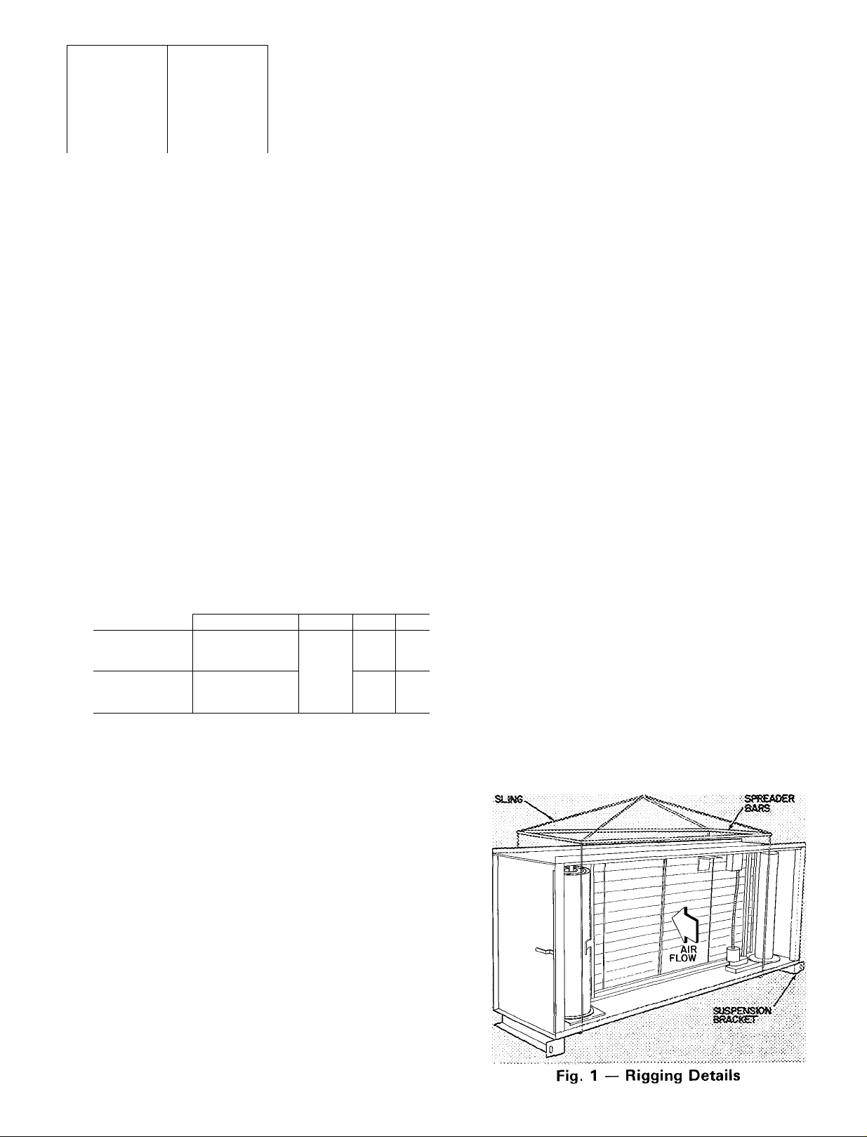
Step 2 — Rig Roll Filter Section — Section is
designed for overhead rigging only. Do not removS
shipping skids until RFS is ready to be moved to
final location. Whenever RFS is moved, use slings
and spreader bars to prevent damage to enclosure
(Fig. 1). Brackets on entering air end of section are
for suspension and are not to be used for rigging.
Refer to base unit installation instructions as
required.
Step 3 — Suspend Roll Filter Section — Sec
tions are supplied with suspension brackets on air
inlet end of channel leg supports (Fig. 1). Unit sizes
08 thru 57 may be suspended by these brackets and
by downstream component bolted to outlet flange.
Size 90 may not be suspended.
Step 4 — Make Airway Connection — Holes in
RFS flanges match holes in 39E base unit sections.
Assemble sections using fasteners shipped in cloth
bag in RFS. For outdoor installation, apply black
caulking gasket on inlet and outlet flanges. Gasket
is shipped in RFS.
Step 5 — Review RFS Components — Fa
miliarize installer with RFS interior before proceed
ing with installation of power wiring and filter media
roll. This simplifies installation and prevents
damage to equipment. Refer to Fig. 2 thru 5.
Step 6 — Install Power and Control Wires —
Junction box is located on right-hand side of RFS
as shown in Fig. 2 and 3. Install a separate fieldsupplied power disconnect. On 39ER roof-curbed
units, route wires internally. Install all outdoor
wiring in accordance with local codes. Connect to
pigtails LI and L2 provided. Also connect green
ground wire found in junction box.
Tex/ continued on page 8
© Carrier Corporation 1978
Form 39E-11SI
Page 2
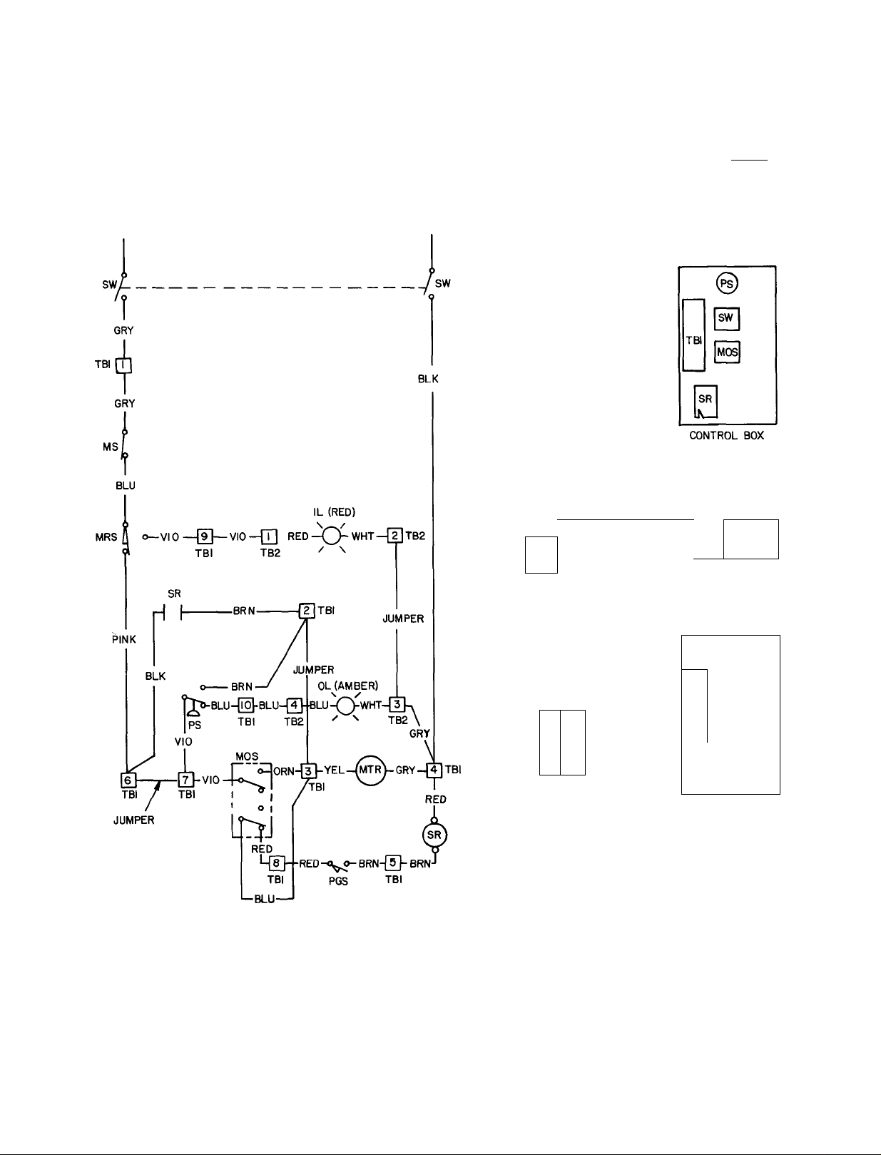
CONTROL BOX (ITEM 81 DETAILS
PRESSURE SWITCH
ADJUSTING SCREW
(UNDER RED CAP)
PRESSURE SWITCH
HIGH-PRESSURE
PORT
POWER SWITCH
(ON-OFF)
MANUAL OVERRIDE
SWITCH
(AUTO-MANUAL)
CONTROL BOX
LOWER ACCESS
PANEL
1 — Access Door (both sides)
2 — Suspension Bracket
3 — Supply Spool Assembly
4 — Media Runout Switch
5 — Media Switch
6 — Pulse Generator Switch
7 — Junction Box (position varies; see text)
8 — Control Box
9 — Take-Up Spool Assembly
10 — Idler Shaft (both sides)
Fig. 2 — Roll Filter Section, RFS1 Shown
ROLL FILTER SECTION DESCRIPTION
(Fig, 2 and 3)
........
AU sections have side access
doors hasisg safety latches, A 1 4~in. x 20 lx)ií
prevents door latch from opening unless bolt is
removed. (Do not operate air system when an>
access door is open. Be sure to replace safety bolt
after dootx are closed.) Left-hand door provides
access to roll media supply spool and a media
switch. Right-hand side of section, in addition to
take-up spool and its motorized gear drive, con
tains also a control panel, a field wiring jtmetion
11 — Motor Gear Drive Assembly
12 — Seal (both sides)
-----------
Media Path
box, and where applicable, an mdicator light box
for remote mounting.
The 65-ft of roll media advance from left to
right as shown. ,Medta Is monitored by a runout
switch and a metering device for full span media
travel. Replacement rolls of filter media (65-ftl
may be shipped with section for future use,
i,argest model (39E-90) consists of 2 roll media
assembUes in a common enclosure, lipper assem
bly (slave) Is coupled to lower assembly for
tandem operation by a common control drive
arrangement.
Page 3
MODEL
SIZE
RFS
RFS — Roll Filter Sections
39E
08 08
10,12 11 6 5,810 6,960 330 1-11-1/2 6-
12
15,18
18
21
26
32
39 39
57 48,57
75,90 91
90
FILTER
AREA
(sq
21 21
26 27 3 13,800 16,560 440 3- 8 832 32 8 16,550 19,860 490 3- 8 9- 9
SINGLE-MEDIA ROLL SECTIONS
CAPACITY
tt)
500 FPM
10 0 5,000 6,000 305 1-11-1/2 5- 11 2-7
19 5 9,750 11,700 375 2-10-1/2 7- 7 3-6
4
43 2 21,600 25,920 510 4-10 962 0 31,000
(cfm)
600 FPM
10,700 12,840 400 2-10-1/2 8-
37,200
WEIGHT
(lbs.
approx)
630 5- 8 11-
MEDIA
ROLL
HEIGHT
(ft-in.) A В
9
3
3
9
9
ROLL FILTER SECTION
2-7
3-6
4-3-1/2 7-9-3/4
4-3-1/2 9-3-3/4
5-5-1/2 9-3-3/4
6-3-1/2 11-3-3/4
DOUBLE-MEDIA ROLL SECTIONS
2
46,100
55,320 825 3- 8
13-3 8-4
Fig. 3 — Physical Data and Dimensions, 39E Roll Filter Sections
DIMENSIONS (ft-in.)
C
5-5-3/4 2-4 100
6-3-3/4 2-4
7-1-3/4
7-9-3/4 3-3
12-9-3/4 8-1
FILTER
FACE
D (sq ft)
3-3
4-0-1/2 27 6
4-0-1/2 33 1
5-2-1/2 43 2
6-0-1/2 62.0
AREA
11 6
19 5
21 4
92.2
Page 4
MEDIA SWITCH
BOX
LI AND L2
- CONNECTIONS
(PIGTAILS)
LI
BLK
sw r
GRY
MS
BLU
MRS i\ o
PINK
i
___
-------------
VIO
115 VOLTS, 60 HZ
230 VOLTS,50 HZ
----------TBI
L2
WHT
BLK
sw
MEDIA RUNOUT
SWITCH BOX
MOTOR CONNECTION
MOTOR CONNECTION
JUNCTION BOX
WIRING JUNCTION
BOX
•JUMPER
TBI TBI
------------
MANUAL UNIT ARRANGEMENT
■YEL (mTr)
----------------
GRY —0
—^ TBI
(INDOOR UNIT ONLY)
LABEL DIAG NO.
60Hz 3INC20-I064
50Hz 3INC 20-1074
Fig. 4 — Label Wiring Diagram, 39E Roll Filter Sections,
Manual, 115-1-60 and 230-1-50
LEGEND
(Fig. 4 and Fig. 5)
IL — Indicating Light
MOS — Manual Override Switch
MRS — Media Runout Switch
MS — Media Switch
MTR — Motor
OL — Operating Light
PGS — Pulse Generator Switch
PS — Pressure Switch
SR — Sequence Relay
SW — On-Off (Power) Switch
TB — Terminal Board
Page 5
f
BLK
115 VOLTS, 60 Hz
230 VOLTS, 50 Hz
L2
WHT
MRS
MEDIA RUNOUT SWITCH
BOX
PGS
PULSE GENERATOR
SWITCH BOX
MOTOR CONNECTION
JUNCTION BOX
INDOOR UNIT COMPONENT ARRANGEMENT
MS
MEDIA SWITCH
BOX
MOTOR
CONNECTIONS
MS
LI a L2 CONNECTION
(PIGTAILS)
ITBEI
WIRING TERMINAL BOX
OL IL
o o
OPERATING a
INDICATING LIGHT
BOX
MEDIA SWITCH
MRS
MEDIA RUNOUT SWITCH
PULSE GENERATOR
BOX
PGS
SWITCH BOX
T
TB
2
WIRING TERMINAL
BOX
OUTDOOR UNIT COMPONENT ARRANGEMENT
BOX
LI AND L2
CONNECTIONS
(PIGTAILS) AND
MOTOR
CONNECTIONS
LABEL DI AG NO
60Hz 3INC20- 1044
50 Hz 3INC20- 1054
Fig. 5 — Label Wiring Diagram, 39E Roll Filter Sections,
Automatic, 115-1-60 and 230-1-50
1 L
OL
O
o
INDICATING LIGHT BOX (REMOTE)
OPERATING a
(OPERATIONAL)
0
0
TBI
|mo s|
0
CONTROL BOX
Page 6

ELECTRICAL COM FOMENT IDENTÍFICATIOM {Rg< 4, 5, 6)
Indksatfng ü^ht OU — Media runout hghi, autoïnaik üecîioas only. Red, acti%atcd by media runout
switch. Illuminates» when filter media on supply
spool is depleted.
Manual Overnde Switch iMOSj — Overrides
automatic advance circuit, activates motor circuit to
permit manual motonr.ed media advancement such
as during media threading operation.
Media Runout Switch |MRS) — Prevents opera
tion of gear motor when supply spool media is de
pleted. Activates red indicating light.
Madia Switch IMS) Desenergizes motor cir
cuit. Allows motor operation from supply side.
Used in conjunction with manual override switch.
Motor {MTRÎ — Operates take-up spool gear
drive to advance filter media, ntermally-protected.
6-rpm, I lô-hp. Gear drive reduces take-up spool
speed to 3 rpm.
Operating light (Ot) — Aatomatic sections only.
Amber, indicates that control switches are in correct
mode, Li^t goes out momentarily when pressure
switch activates motor circuit. If electrical or mech
anical malfunction occurs, light gîses out and stays
out to indicate possible power failure or that pres
sure drop thru airway exceeds air pressure switch
setting due to mechanical failure. Light is re
energized when pressure or power is restored,
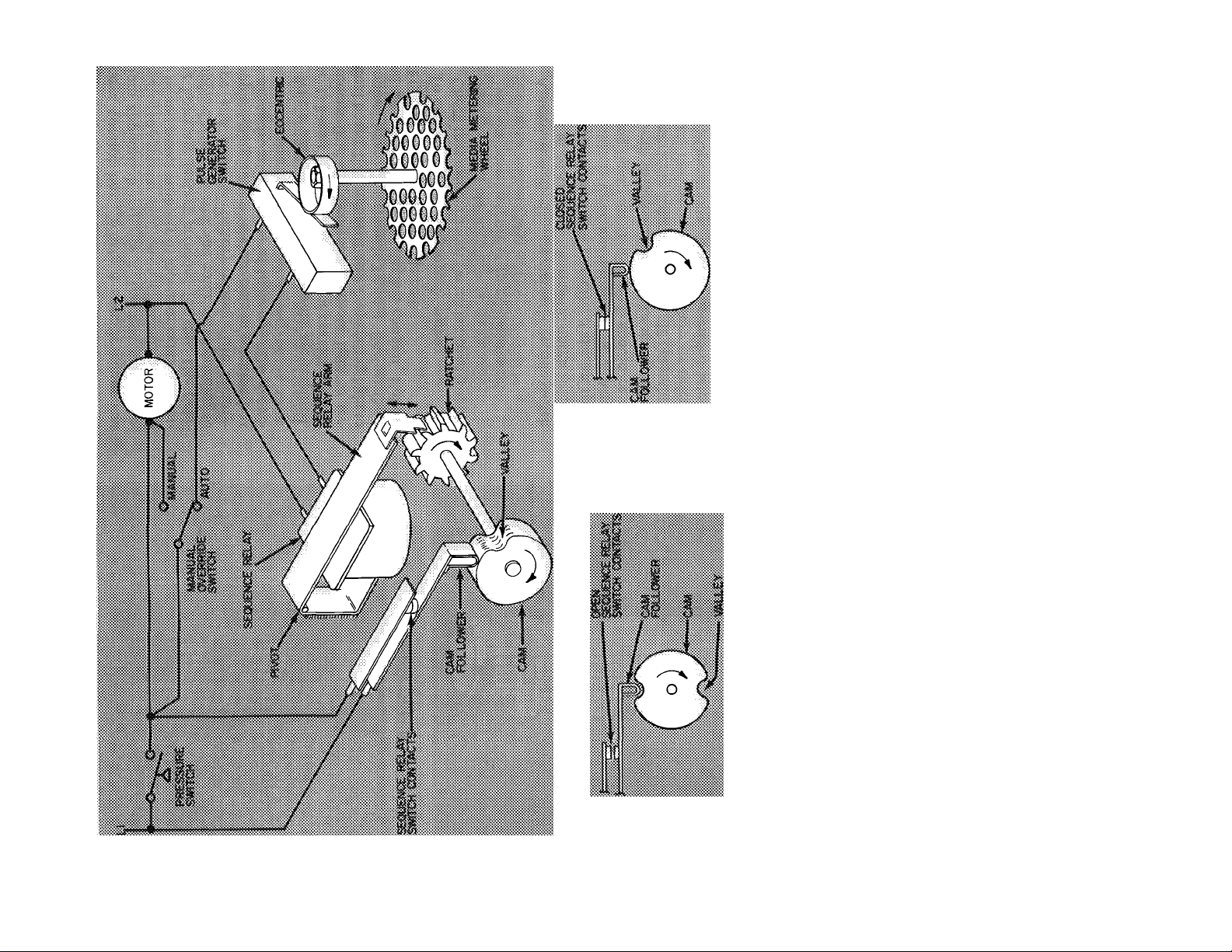
Fulse Gerwmior Switch |PGS> ~- Athomatic
sections only: activated by media metering wheel
cam to operate sequence relay.
Fressure Switch {PS) — Automatic sections only.
Senses pressure drop thru media iu airway. .At preset
pressure (0,5$ in, wg factory setting, adjustable) it
activates motor circuit Camber operating light goes
out). When pressure drops below setting, switch
returns to turn on operating light.
Sequence Relay fSR) — Automatic sections only.
A holding relay that maintains motor operating
mrcait. Senses pulses genmated by pulse ^nerator
switch to advance ratchet cam shaft,
On-Off Switch ISVIQ — Power switch. Controls
all power to motor and control circuit (DPST),
B&WÚ CTS) — Provides quick-connect
termináis for indicator ll^ts or other fmldoonneeted oompoueota,
Ptilsa iSormrator Aaaambly S) Consists
of media metering wheel, pulse generator switch
and sequence relay. Except for making .sure that
media metering wheel tension against media is
suffieient to turn wheel as media passes bv, little or
no service can be performed beyond keeping media
wheel and shaft free of lint and making
sure that electrical connections are intact. The
assembly function.^ a,s follows:
As air pressure increases due to restriction caused
by dirty filtes media, pressure switch closes acti
vating motor to advance media, .Media passing
metering wheel causes wheel to turn. Eccentric
closes pulse generator switch which momcniarily
energizes sequence relay once each rev'olution. Se
quence relay arm advances ratchet wheel one notch
causing relay switch arm cam follower to ride up out
of valley. Sequence relay contacts on relay switch
arm close maintaining pow'er to motor. As media
metering wheel continues to trip sequence relay,
pulses advance ratchet until catn follower drops into
valley thus de-energizing motor power. Media
advancement ceases. Valley-to-valiey interval,
which depends on media metering whxl diameter
and number of valleys. Is “programmed” to operate
motor so that a predetermined length of media h
advanced into airway for full span operation.
Ratchet and cam may be advanced manually (clock
wise} by either turning cam or repeatedly pressing
on sequence coil arm such as when operational
check requires manual advance.
Page 7
ш
_>
SI
E
0)
и
(О
< Е
>- (б
о ™
■н О)
<0 я
® Q
g Ü
«=5
ф л
í>
о. со
(О
03
Page 8

Text continued from page I.
Install remote indicator light box shipped with
outdoor automatic sections per job plans. Indicator
light box on indoor automatic units is fastened
above control box. Where a specific equipment
room application requires it, this box may be re
located to a similar location on left-hand end of RFS
to permit easier visibility of indicator lights. Mount
ing holes are factory provided for this. Use fieldsupplied wiring of type and color corresponding to
type and color of factory wiring. Use factorysupplied plug button to close hole in junction box
resulting from relocation of light box. Do not re
locate junction box.
Where additional indicator lights are required,
use 1 / 2-watt (maximum) lights of correct voltage.
Connect field-supplied media runout light to ter
minal board 2, terminals 1 and 2; operating light to
terminal board 2, terminals 3 and 4. Enclose these
and all wires in rigid or flexible conduit. Follow
NEC and all other applicable codes.
To check that RFS is properly wired:
1. Check that media runout switch is closed (supply
media roll in place).
2. Turn on power supply at fused disconnect.
3. Set media switch (MS) at ON.
4. Automatic section — set manual override switch
(MOS) at MANUAL (automatic only).
5. Set power switch (SW) at ON. Take-up spool
should turn in direction shown in Fig. 2. Amber
operating light (automatic units) should be on.
6. Set on-off switch at OFF. Take-up spool will
stop; operating light will go out. If operation is
incorrect, review wiring procedure or refer to
Service, Operational Checks described later as
required.
Fig. 7 — Threading Details (Step 6)
Step 7 — Install Roll Filter Media — The follow
ing procedure applies to installation of initial roll
filter media as shipped with section. If replacing
dirty filter media, refer to section entitled Replacing
Dirty Filter Media.
1. Open take-up side access door. Set power switch
at OFF, set manual override switch at MAN
UAL (Fig. 2). Open supply side access door. Set
media switch at ON.
2. Begin with lower assembly on dual roll sections.
Lift supply spool shaft upper retainer, swing
out upper end of spool shaft.
3. Install media roll on spool shaft. Note correct
position of roll so that as media unwinds, fluff
side of media will be facing into airstream
(Fig. 2).
4. Untie and remove plastic wrapper from media
roll. Replace upper end of spool shaft in
retainer.
5. Remove threading rod from its storage clips on
supply compartment bulkhead.
6. Locate eyelet end of threading wire lying in
Fig. 8 — Paper Leader Installed on
Take-Up Core (Step 9)
media track. Install threading rod on filter
media paper leader so that threading rod eyelet
is trapped at about midpoint of leader (Fig. 7).
7. Pull take-up end of threading wire so that filter
media passes around supply side idler shaft and
traverses airway from supply side to take-up
side. Be sure that threading rod, paper leader
and filter media pass thru supply side seals with
out force. Check that threading operation
follows route shown in Fig. 2 so that media
emerges thru take-up side seals and around
take-up side idler shaft without wrinkling or
tearing.'
8. Remove threading rod and wire from paper
leader. Replace threading rod on its storage
clips on supply side. Threading wire may be
discarded.
9. Insert leader behind strap on take-up core
(cardboard tube) and fold it over itself as shown
in Fig. 8.
Page 9

10. Set power switch at ON so that take-up spool
makes 2 complete turns. Be sure that paper
leader lies flat against media so that as media
winds around core it does not come loose or
bunch up. Be sure that media is free of wrinkles
and travels without snagging. Again, check that
media is routed as shown in Fig. 2.
11. Dual roll sections — Repeat threading pro
cedure for upper media roll. Note that a second
threading rod and wire are provided. After
upper roll is threaded, about 4 turns of media
will be wound on lower take-up spool. Do not
operate gear motor any more than necessary.
Media cannot be rewound onto supply spool.
12. Set manual override switch at AUTO, as appli
cable. Then set power switch at ON.
13. Perform operational checks as required. Close
and secure access doors. Refer to air handling
unit operating instructions as applicable.
START-UP
Step 8 — Perform Electrical Control System
Checkout — Control system designed and factory
set to provide full-span media advancement when
required. Before performing Operational Check,
and Complete Electrical Check, described below, re
view Roll Filter Description (page 8), Wiring Dia
grams (Fig. 3 and 4) and Component Description.
Be sure that media is correctly installed and routed
as shown in Fig. 2.
cAwmmt mm ^
mm whidi m Siee« Mv&tsm be re-
OPERATIONAL CHECK (all power is off)
1. Automatic Units — set manual override
switch at AUTO.
2. Set media switch at OFF.
3. Turn on power to unit at fused disconnect
switch.
4. Set power switch at ON. Read steps 5, 6 and
7; perform in relatively rapid succession.
5. Set media switch at ON.
Manual Units — Motor should operate.
Automatic Units — Amber operating light
should light up.
6. Automatic Units — Set manual override
switch momentarily at MANUAL. Motor
should operate momentarily.
7. Swing media runout switch arm away from
supply media spool. Depress media runout
switch (micro-switch behind runout arm).
Manual Units — Motor should stop.
Automatic Units — Media runout light (red)
should light up.
8. Release media runout switch. Restore control
circuit to operating status (i.e. media switch at
ON, runout switch at AUTO., power switch at
ON).
COMPLETE ELECTRICAL CHECKOUT to be
performed by a qualified electrician only.
Because it has fewer controls, the complete elec
trical checkout of a manual roll filter section is the
same as the operational check described above. The
following procedure applies to automatic roll filter
section only.
1. Set power switch at OFF. Turn power off at
external fused disconnect switch.
2. Remove access panel below control panel
(Fig- 2).
3. Restore power at fused external disconnect
switch; set power switch at ON.
4. Perform Operational Check described pre
viously as required.
5. Connect a 36-in. (approximate) piece of 3/8-in.
tubing to high-pressure tap on control panel
face (Fig. 2).
6. Blow on tube to close pressure switch to simu
late high pressure caused by dirty filters. Media
advance motor should operate. Refer to Pres
sure Switch Adjustment described later as
required.
7. Maintain pressure on pressure switch long
enough to perform step 8.
8. As media advances, allow media metering wheel
to revolve thru one revolution. This closes pulse
generator switch and energizes sequence relay
(Fig. 5 and 6). Review Pulse Generator Assem
bly description as required.
9. Set power switch at OFF. Shut off power at
fused disconnect.
10. Remove tubing from high-pressure tap.
11. Reset sequence relay by manually turning cam
clockwise until relay switch arm drops into
valley of cam (either cam on sizes 75 and 90).
12. Replace control box cover, restore power at
fused disconnect switch and set all switches
as follows:
Media Switch — ON
Manual Override Switch — AUTO.
Power Switch — ON
13. Roll filter section is again ready for automatic
operation. Check that all is in order. Close and
secure access doors before leaving job site.
Page 10

SERVICE
Replacing Dirty Filter Media — Rethreading
clean media roll is not necessary. When clean media
is to be installed, simply attach leader of clean media
roll to trailer of depleted (dirty) media roll as
follows;
1. Shut off system air fan. Open both side access
doors (Fig. 2). Automatic units — set manual
override switch at MANUAL.
2. Check that supply media roll has been depleted.
Swing media runout arm away from supply
spool and set media switch at ON so that motor
will advance remaining media. When paper
trailer is exposed, release runout arm (stopping
motor). Then set media switch at OFF.
NOTE: If a complete increment of clean media
can be exposed to airway before paper trailer on
supply spool is exposed, adjust media runout
switch as described later so that clean media will
not be wasted.
3. Disengage paper trailer from supply core (card
board tube). Do not operate motor at this time.
4. Lift supply spool upper shaft retainer, swing
out upper end of shaft. Remove the now empty
core from supply spool. Do not damage or dis
card core.
5. Unpack replacement supply media roll, install
it on supply spool. Replace upper end of spool
in retainer. Note correct position of roll so that
as media unrolls fluff side of media will be facing
into airstream (Fig. 2).
6. Connect paper leader of replacement media roll
to paper trailer of depleted media roll by using
threading rod (Fig. 9).
7. Dual-roll sections only — Jog media switch to
expose paper trailer of upper (slave) media roll.
As this is done, be sure that threading rod in
splice in lower media rolls passes smoothly
around supply-side idler shaft and then thru
supply-side seals without snagging or wrinkling.
Repeat steps 2 thru 6 to replace upper media
roll.
8. Set media switch at ON to draw splice(s) across
airway opening. Check that threading rod(s),
splice(s) and media travel smoothly. When
(lower) threading rod and splice reach take-up
side set media switch at OFF.
9. Remove threading rod to disconnect paper
trailer of depleted roll from paper leader of
replacement roll. Replace threading rod on its
storage clips in supply side.
10. Lift take-up spool shaft retainer; swing out
upper end of take-up spool. Remove depleted
media roll from take-up spool. Pack dirty media
roll in now-empty replacement roll carton. Dis
pose of dirty media roll as suitable.
11. Install empty core (cardboard tube removed in
step 4) on take-up spool. Replace upper end of
take-up spool shaft in shaft retainer.
12. Insert leader behind strap on take-up core
(Fig. 8). Fold leader over itself. Note rotation
of take-up spool (Fig. 2).
13. Set power switch at OFF.
14. Set media switch at ON.
15. Jog power switch so that about 2 turns of clean
media roll winds up on take-up spool to secure
paper leader end of roll on to core. On dual-roll
sections this will also advance upper media roll
so that splice will pass thru upper take-up-side
seals, pass around take-up idler shaft and reach
upper take-up spool.
16. Dual roll sections — Disconnect splice in upper
depleted and replacement rolls; connect upper
replacement media roll to upper take-up spool
(i.e. repeat steps 9 thru 15). Be sure that media
travels smoothly and that paper leader is evenly
secured. Replace threading rod in its storage
clips on supply side.
17. Manual Units — Leave media switch at ON. Set
power switch at OFF.
Automatic Units — Set manual override switch
at AUTO. Set media switch at ON, then set
power switch at ON.
18. To check that all is in order, perform Opera
tional Checks as required. Close and secure
access doors before leaving job site.
r
Fig. 9 — Replacement Media Roll Spliced
to Depleted Media Roll
Media Runout Switch (Fig. 2) — Switch is factory
set to prevent media advancement when supply
spool media is depleted. Incorrect setting may
cause excessive media to remain on supply spool
or cause media to be pulled off supply spool core
before shutting off advance cycle.
Runout switch is activated by adjustable bolt on
runout arm when arm is 3/8-in. away from spool
core. To adjust cutout setting:
10
Page 11

1. Loosen adjusting screw locknut.
2. Turn adjustable bolt so that runout switch opens
when runout arm comes within 3/8-in. of core.
3. Tighten adjusting screw locknut. Recheck
setting.
Pressure Switch (Fig. 2) — As filter media be
comes dirty, high-pressure drop thru media reduces
airflow. Pressure switch is factory set at 0.55 in. wg.
Field adjustment should not be necessary. When
pressure sensed by high-pressure fitting on control
panel face reaches this setting, pressure switch shuts
off amber operating light and energizes pulse gener
ator sequence relay and motor. As clean media ad
vances across airway, pressure drop across media
decreases and switch returns to illuminate amber
operating light. To check and/or adjust pressure
switch setting:
1. Shut off system air fan. Open take-up side
access door. Shut off power at fused disconnect.
Set power switch at OFF.
2. Disconnect yellow or gray motor lead at ter
minal board no. 1 (TBl-3 or 4) to prevent motor
operation. Tape off lead.
3. Set power switch at ON. Turn on power at
fused disconnect.
4. Remove red plastic cap from pressure switch to
expose adjusting screw. Do not loosen 1-in. hex
locknut. Nut is locked to provide mechanical
stop for minimum differential pressure setting.
5. Connect a draft gage to high-pressure port on
control panel.
6. Apply controlled pressure gradually to highpressure port until amber operating light goes
out. Note draft gage reading. This is switch set
point (factory setting 0.55 in. wg).
7. Turn adjusting screw counterclockwise to de
crease static pressure setting or clockwise to
increase static pressure setting as required. A
1/2 turn changes setting approximately 0.13
in. wg.
8. Remove draft gage. Replace red plastic cap on
adjusting screw.
9. Shut off power at fused disconnect. Set power
switch at OFF. Reconnect motor lead. Turn on
power at fused disconnect. Set power switch
at ON.
10. Perform any other operational checks as re
quired. Close and secure access door. Restore
air system operation.
Motor Gear-Drive Assembly (Fig. 2 and 10) —
Assembly advances clean media across filter section
airway. It consists of a motor and drive sprocket,
a roller chain and a take-up spool sprocket on a
support plate. Chain tension is factory set so that
deflection of chain at midpoint is 1/4-inch. To ad
just chain tension, loosen motor mounting bolts (3),
reposition motor on slotted mounting holes in
support plate until correct tension is achieved.
Tighten motor hold-down bolts.
MOTOR
SUPPORT PLATE
MOTOR MOUNTING
BOLTS. LOOSEN FOR
TENSION ADJUSTMENT
Fig. 10 — Motor Gear-Drive Details
MOUNTING HOLES (4)
TAKE-UP
SPOOL
SPROCKET
Lubricate chain with a light graphite oil once each
year.
Media Tension Brake (Fig. 11) — Brake is
mounted on bottom panel of supply spool side to
provide tension on supply spool at bottom end of
spool shaft. Two brake shoes held in place by 2
helical springs cause friction (drag) required for
proper media tension. Brake assembly includes
supply spool bearing surface and slotted axis shaft.
Except for making sure that helical springs and shoes
are in tension, no other maintenance is required.
Shear Pin — Take-up spool shaft is fastened to
keeper on take-up spool disk at base of spool by a
bolt and locknut. This bolt acts as a shear pin to pre
vent damage to motor gear-drive. In the event of
mechanical failure which could cause excessive
tension on motor gear-drive, bolt will shear allowing
motor to operate freely and continuously. Eventu
ally, amber operating light will go out (as described
elsewhere) and stay out as indication of malfunction.
Cleaning and Lubrication — The only cleaning
necessary in addition to general housekeeping is
removal of loose fibers around shaft bearings. Shaft
bearings and gear motor require no routine main
tenance. Refer to specific component description for
additional information as required.
BRAKE
SKIES:
Fig. 11 — Media Tension Brake
11
Page 12

For replacement items use Carrier Specified Parts.
Manufacturer reserves the right to discontinue, or change at any time, specifications or designs without notice and without incurring obligations.
Book 3
Tab lib
Form39E-11SI Supersedes 31 NA-1 SI
PrintedinUSA 5-78 PC201 Catalog No 533-925
 Loading...