

Page 1
iupeeseoeo '6'/
Draw-Thru Central Station Weathermaker
SuPcesfi^cC) ay 0/7/
39B
INDEX
PAGE
PREINSTALLATION
INSTALLATION
Base Unit Assembly
Accessory Assembly
Unit Suspension and Mounting
Piping
Coil Removal and Reversing
Duct Connections
Motor and Drive
Belt Guard
START-UP
SERVICE
Coil Removal
Fan Section Access
Fan Shaft Bearing Replacement
Fan Shaft Removal
Fan Wheel Removal
PREINSTALLATION
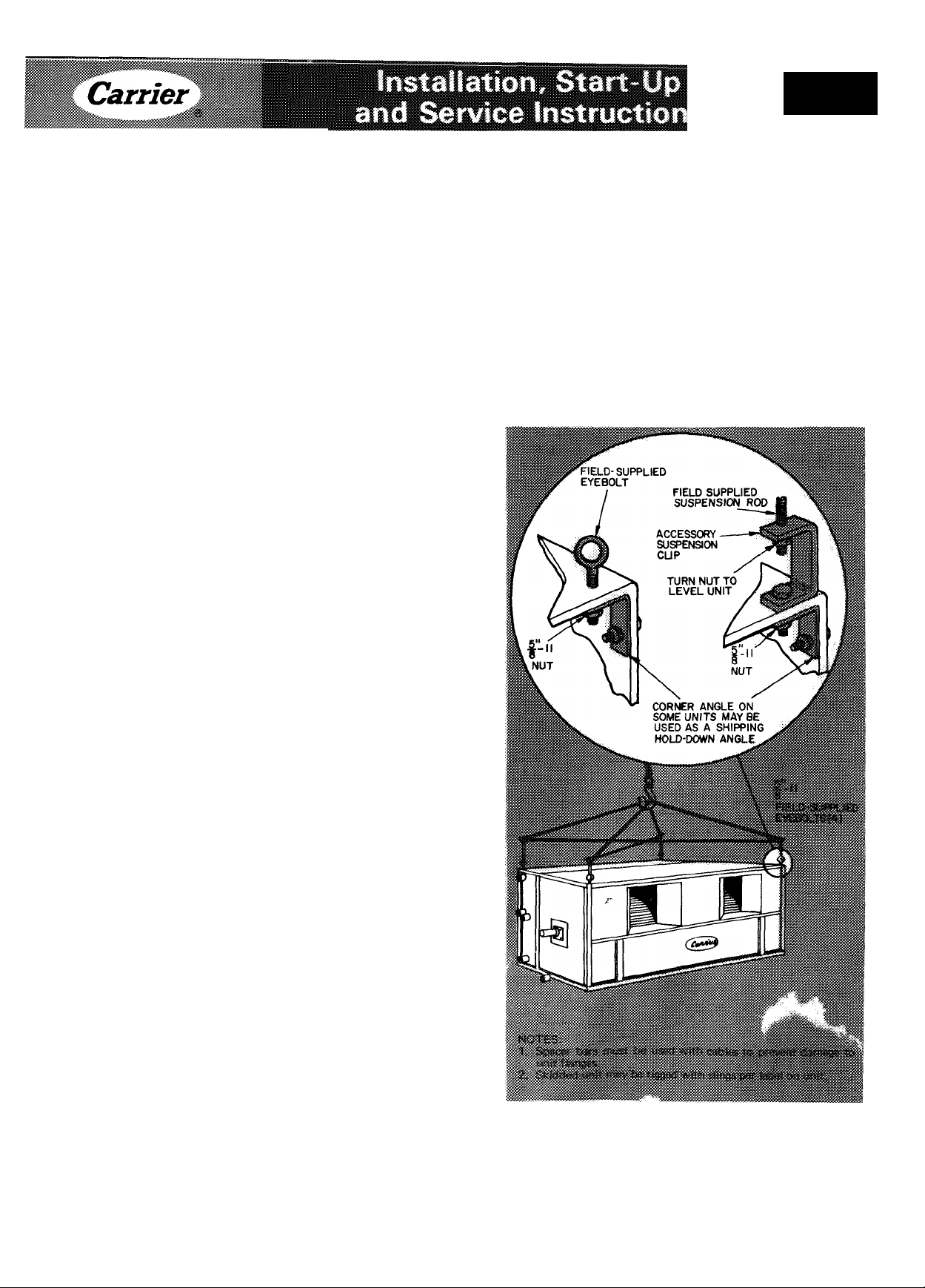
1. Use spacer bars when rigging to avoid bending
unit flanges per Fig. 1.
2. Check items received against packing list and
Tables 1,2, and 3. Notify Carrier at once of
any discrepancy.
3. Examine for damage incurred during shipment.
Especially check for bent fan wheel or shaft
which may result in future vibration problems.
If any damage is found, immediately file claim
with transit company.
4. Check fan wheel setscrews (sizes 040-060) or
fan wheel clamps (sizes 070-140) for secure
ness. Refer to Table 4 or Fig. 2 respectively.
a. Bolt threads with a dark-green finish require
no lubrication. Carefully lubricate all other
bolt threads with oil. Do not oil fan shaft.
b. Tighten clamps evenly.
5. Exercise care in handling all equipment.
6. If unit is to be stored for more than t, ’o v,eeks
prior to installation, observe the following
precautions:
a. Choose storage site that is kvel and ; +urdy.
to prevent undue stress or permanei t dis
tortion to fan. Do not subject bearings to
direct sunlight or temperatures in excess of
1.
180 F. '
1
6
6
9
14
15
19
19
19
22
22
23
23
23
23
23
24
b.c.Protect bearings and rotating components
against moisture, abrasives and corrosion.
Cover entire unit with a tarp or plastic
coverall. Extend cover under unit if stored
on ground. Moisture and condensation can
cause loosening of internal insulation.
Periodically rotate fan shaft slowly by hand.
Fig. 1 — Rk , and Suspension DetailiS
© Carrier Corporation- 1971
*
Form 39B-1SI
Page 2
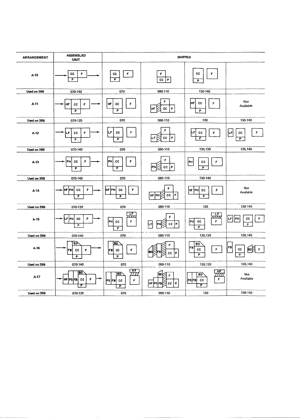
Table 1 — 39B Type "A" Unit Arrangements (Horizontal With Reheat)
Base unit and accessories on 39BA, sizes 040 thru 060 are shipped completely assembled.
Page 3

Table 1 — 39B Type "A" Unît Arrangements (Horizontal With Reheat) (cont)
Base unit and accessories on 39BA, sizes 040 thru 060 are shipped completely assembled.
r
LEGEND
BD — Bypass Duct
CC — Cooling Coil and Reheat
Coil Section
F — Fan Section
FB — Face & Bypass Damper Section
NOTE: Combination mixing box and filter assembly (MB), not shown, is shipped separately.
HF — High-Velocity Filter Section
LF — Low-Velocity Filter Section
P — Base Pan
PD — Preheat Duct Extension
PH — Preheat Coil Section
PS — Plenum Section
Separate Crates or Skids
Location for Shipping only on one Skid.
Page 4

Table 2 ~ 39B Type "B" Unit Arrangements (Horizontal Without Reheat)
Base unit and accessories on 39BA, sizes 040 thru 060 are shipped completely assembled.
ARRANGEMENT
B-10
Used on 39B
B-11
Used on 39B
B-12
Used on 39B
B-13
Used on 39B
ASSEMBLED
UNIT
C
^
070-120
070-120
P
C
F
C
H
P
F
Hcc
SHIPPED
LF
Shipped
Assembled
070-110 Used on 39B
PH
Shipped
Assembled
070-110 Used on 39B
Shipped
Assembled
I
ARRANGEMENT
B-17
Used on 39B
B-18
Used on 39B
B-20
B-21
ASSEMBLED
UNIT
■ p
F
c
F
s
B
c
070-120
P
F
c
L
F
L
F
F
S
B
c
070-120
\
P
F
c
F
S
B
c
070-120
PD BD
070-120 070-110
PD BD
P
S
\
F
P
c
F
B
H
c
Shipped
Assembled
070-110
P
F
c
s
B
c
070-110
Shipped
Assembled
070-110
PD BD
P
F
S
B
«
P
F
s
B
§
SHIPPED
\
IlI
F
N
p
P
s
P
F
s
B
p
s
F
B
P
s
120
F
B
120
120
PD BD
M
120
F
B
PD BD
BD
P
F
s
B
Used on 39B
B-15
Used on 39B
B-16
Used on 39B
070-120 070-110
P
c
H
c
p
070-120 070-110
F
c
F
B
c
070-120 070-120
Shipped
Assembled
120
I
120
Used on 39B 070-120
B-22
Used on 39B 070-120
B-23
Used on 39B
LEGEND
BD — Bypass Duct
— Cooling Coil Section Only P
CC
— Fan Section PD
F
— Face & Bypass Damper Section PH
FB
— High-Velocity Filter Section
HF
LF
PS
NOTE: Combination mixing box and filter assembly (MB), not shown, is shipped separately.
070-110
PD BD
1
___
p
c
B P
s
c
® H
PD BD
F
P
B
H
070-120
V
F
PD BD
p
F
p
c
s
B
c
H
070-110
Shipped
Assembled
070-110
□ □ Separate Crates or Skids
Location for Shipping oniy on one Skid
120
P
F
F
s
B
PD t BD
“
P
H
120
p-y
F
F
B
Page 5
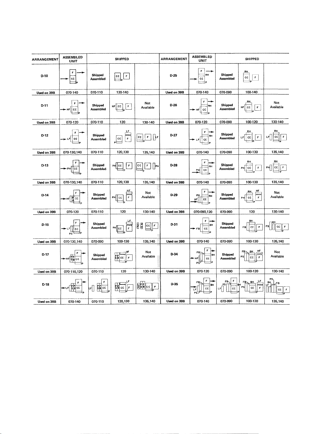
Table 3 — 39B Type "D" Unit Arrangements (Vertical)
Base unit and accessories on 39BA, sizes 040 thru 060 are shipped completely assembled.
LEGEND
BH - Bypass Heat Section LF — Low-Velocity Filter Section
CC — Cooiing Coil Section P — Base Pan
F — Fan Section PH — Preheat Coil Section
FB — Face & Bypass Damper Section PS — Plenum Section
HF — High-Velocity Filter Section RH — Reheat Coil Section
NOTE: Combination mixing box and filter assembly (MB), not shown, is shipped separately.
□ □ Separate Crates or Skids
Location for Shipping only on one Skid
Page 6
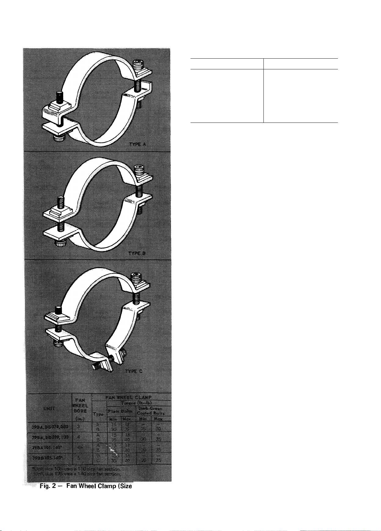
Table 4 — Setscrew Torques
076-140)
SETSCREW SIZE
10
1/4 52.7- 71 3 in.-lb
5/16
3/8 168.3-227.7 in.-lb
7/16
1/2
5/8
3/4
INSTALLATION
General
TORQUE
22 5- 30.5 in.-lb
103.7-140.3 in.-lb
22.1- 29 9 ft-lb
32 3- 43 7 ft-lb
78.2-105.8 ft-lb
107.9-146.1 ft-lb
DO NOT
1. Remove protective caps from coil piping con
nections until ready to connect piping.
2. Bend or mutilate coil fins.
3. Remove protective cover or grease from fan
shaft until ready to install sheave.
4. Lift by fan shaft extension or coil connections.
5. Remove fan drive from boxes until ready to
install, to prevent loss of parts and installation
information labeled on boxes.
6. Lift face and bypass damper assembly without
providing support under center of assembly.
DO
1. Use spacer bars per Fig. 1 when rigging to avoid
bending unit flanges.
2. Make piping and duct connections in accord
ance with standard practices. Refer to Carrier
System Design Manual for details.
3. Leave sufficient clearances for:
a. Condensate trap.
b. Removal of fan shaft and coils.
c. Service of filters, fan motor, bearings,
damper linkage, and damper motors (at least
30 inches).
d. Piping to permit removal of fan guard.
Base Unit Assembly (Fan and Coil Sections)
NOTES:
1. Base unit and accessories on 39BA sizes 040
thru 060 (arrangements A, B, and D) are
shipped completely assembled, except for
accessory mixing box which is shipped
separately.
2. More holes may exist than indicated by these
instructions. Use only those which line up.
3. Fastener package is shipped with each fan
section. Sealing compound is shipped inside
belt guard.
4. Remove any accessories attached to base unit
that are not in their final location per Tables 1,
2, and 3.
5. Unit suspension is simplified by completely
assembling units prior to rigging.
6. Unit sizes 130 thru 140 must be assembled on a
platform for suspended applications.
Page 7
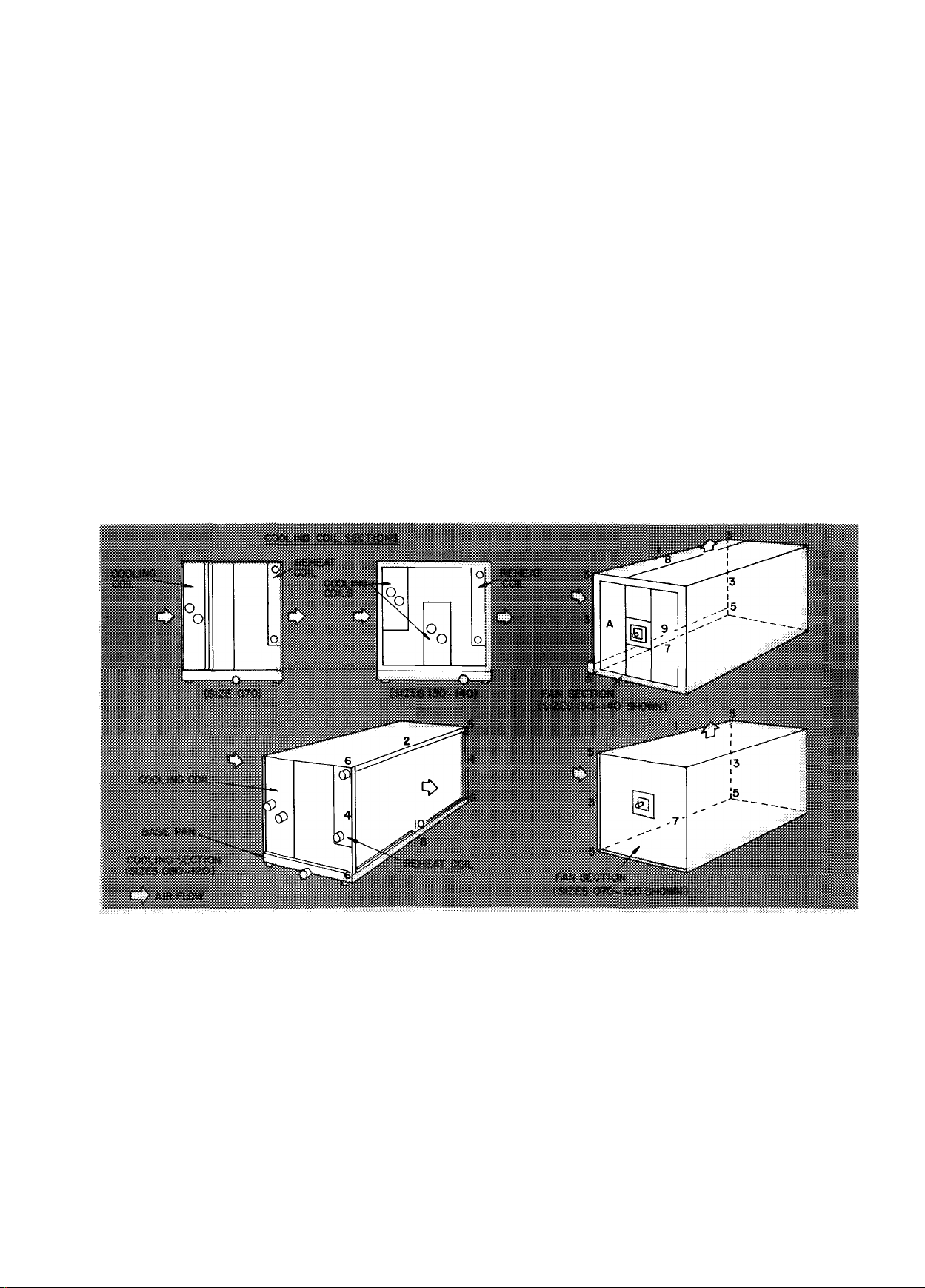
UNITS 39BA,BB SIZES 070 THRU 120 (Arrange
ment A) - Refer to Fig. 3 and Table 1.
1. Remove shipping skid(s) and apply sealing
compound to flanges on air intake side of fan
r
section.
2. Face air intake side of fan section toward air
discharge side of cooling coil section.
3. Fasten flange 1 to 2 with five 3/8-16 x 3/4-in.
hex head cap screws, lockwashers and flange 2
weld nuts.
4. Fasten flanges 3 to 4 with one 3/8-16 x 3/4-in.
hex head cap screw, lockwasher, and hex nut
per two flanges.
5. Fasten corners 5 to 6 with one 3/8-16 x 3/4-in.
hex head cap screw, lockwasher, two plain
washers and hex nut per two corners. Corner
holes are 11/16-in. diameter.
6. Fasten external flange 7 to 8 with three
3/8-16 X 3/4-in. hex head cap screws, lockwashers, and flange 8 weld nuts.
7. Tighten all screws securely.
UNITS 39BA,BB SIZES 130 THRU 140 AND
39BC SIZES 135 AND 140 (Arrangement A) —
Refer to Fig. 3 and Table 1.
1. Follow preceding steps 1 and 2.
2. Remove fan section panels A and B. Provide a
cardboard walkway on fan section bottom to
protect insulation.
3. Fasten flange 1 to 2 with seven 3/8-16 x 3/4-in.
hex head cap screws, lockwashers, and flange 2
weld nuts.
4. Fasten flanges 3 to 4 with five 3/8-16 x 3/4-in.
hex head cap screws, lockwashers, plain
washers, and hex nuts per two flanges.
5. Fasten riser panel 9 to lip 10 with six
1/4-20 X 1/2-in. self-tapping screws and Hp 10
engagement holes.
6. Tighten all screws securely.
7. Remove cardboard walkway from fan section
and replace panels A and B.
Fig. 3 — Base Unit Assembly for 39BA,BB070-140 and 39BC135 and 140 (Arrangement A)
Page 8
UNITS 39BA,BB SIZES 100 THRU 120 (Arrange
ment D, except D-17 and D-18) — Refer to Fig. 4
and Table 3.
1. Remove shipping skids and apply sealing
compound to flanges on air discharge side of
cooling coil section.
2. Place air intake side of fan section on top of air
discharge side of cooling coil section, reheat
coil section or bypass heat section.
3. Fasten flange 1 to 2 with three 3/8-16 x 3/4-in.
hex head cap screws, lockwashers per two
flanges and flange 2 weld nuts.
4. Fasten flanges 3 to 4 with one 3/8-16 x 3/4-in.
hex head cap screw, lockwasher, and hex nut
per two flanges.
5. Fasten comers 5 to 6 with one 3/8-16 x 3/4-in.
hex head cap screw, lockwasher, two plain
washers, and hex nut per two corners. Corner
holes are 11/16-in. diameter.
6. Tighten all screws securely.
Arrangements D-17 and D-18
1. Follow preceding steps 1 thru 5.
2. Fasten spray humidifier or preheat coil section
with bypass when supplied to cooling coil
section per accessory assembly.
3. Fasten flange 7 to fan section side A with three
1/4-20 X 1/2-in. self-tapping screws and side A
engagement holes.
4. Line up flanges 8 and 9 and drill two engage
ment holes in each flange 9 with a no. 3 drill.
5. Fasten flanges 8 to 9 with two 1/4-20 x 1/2-in.
self-tapping screws per two flanges.
6. Tighten all screws securely.
UNITS 39BA,BB SIZES 130 THRU 140 AND
39BC SIZES 135 AND 140 (Arrangement D, ex
cept D-18) — Refer to Fig. 5 and Table 3.
NOTE: On arrangements D-31and35, sizes 135
and 140 — first fasten bypass heat section to
cooling coil section per Accessory Assembly, then
proceed with following steps;
1. Remove shipping skid(s) and apply sealing
compound to flanges on air discharge side of
cooling coil section.
Place air intake side of fan section on top of air
2.
discharge side of cooling coil section, reheat
coil section, or bypass heat section.
Cooling coil section —
3.
a. Line up side A of fan section with filler
panel and drill eight engagement holes along
bottom edge of side A with a no. 3 drill.
b. Fasten filler panel to side A with eight
1/4-20 X 1/2-in. self-tapping screws.
4. Bypass heat section or reheat coil section.
a. Place filler panel, removed from cooling coil
section per Accessory Assembly, along
flange 7 of accessory section and butt
against fan section per Fig. 5.
b. Drill seven engagement holes along flange 7
with a no. 2 drill.
c. Fasten filler panel to flange 7 with seven
self-tapping screws.
d. Follow preceding steps 3a and 3b.
5. Fasten flange 1 to 2 with five 3/8-16 x 3/4-in.
hex head cap screws, lockwashers, plain
washers, and hex nuts per two flanges.
6. Tighten all screws securely.
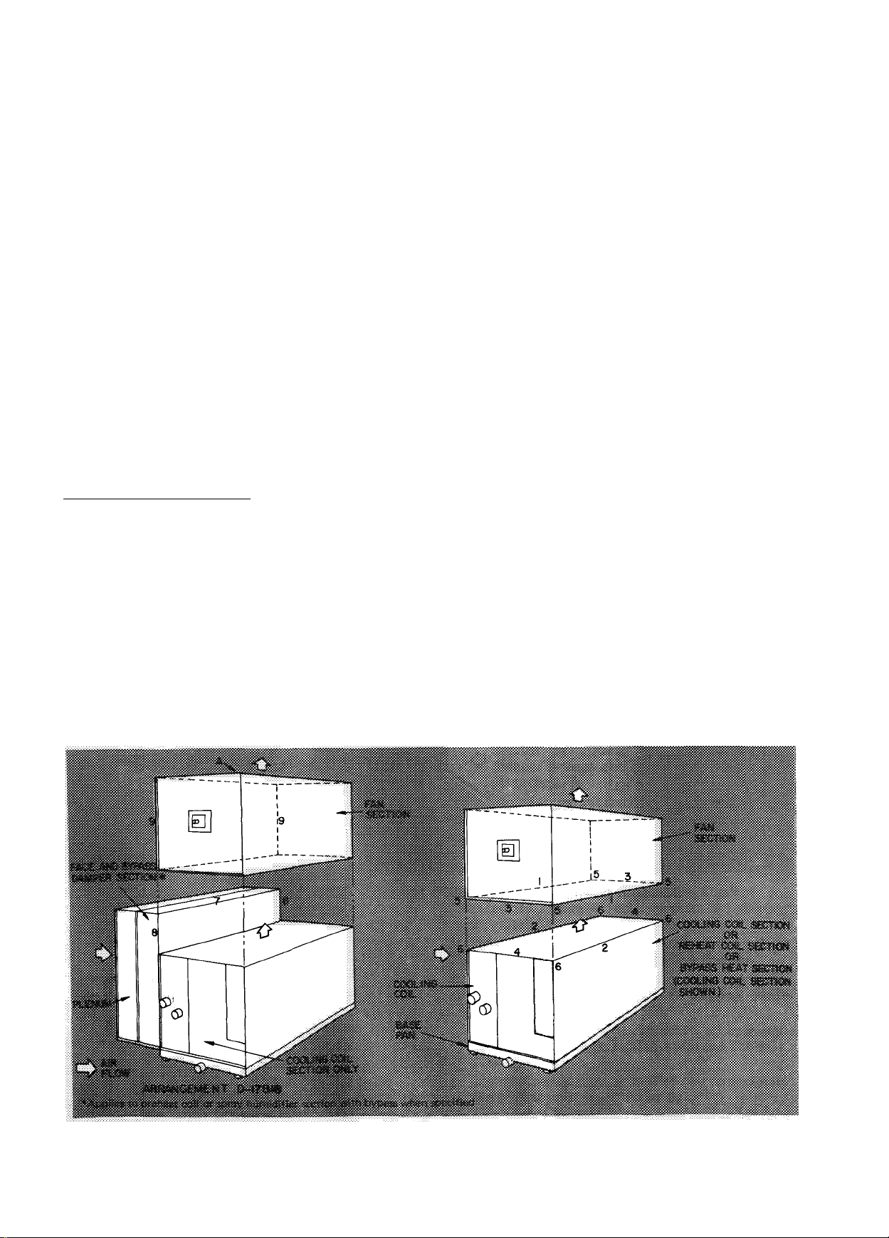
Fig. 4 - Base Unit Assembly for 39BA,BB100-120 (Arrangement D)
8
Page 9

Fig. 5 - Base Unit Assembly for 39BA,BB130-140 and 39BC135,140 (Arrangement D)
Arrangement D-18
NOTE: Duct extension is shipped assembled to fan
section.
1. Remove filler panel from cooling coil section
and discard.
2. Fasten spray humidifier or preheat coil section
with bypass when specified or plenum and face
and bypass damper section to cooling coil
section per Accessory Assembly.
3. Remove shipping skid and apply sealing
compound to flanges on air discharge side of
cooling coil section.
4. Place air intake side of fan section on top of air
discharge side of cooling coil section.
5. Fasten flanges 3 to 4 with seven 1/4-20 x 1 /2-in.
self-tapping screws and flange 4 engagement
holes.
6. Fasten flanges 5 to 6 with two 3/8-16 x 3/4-in.
hex head cap screws, lockwashers, plain
washers, and hex nuts per two flanges.
7. Tighten all screws securely.
Accessory Assembly — Refer to Tables 1,2, and 3.
NOTE; More holes may exist than indicated. Use
only those which line up.
BYPASS HEAT SECTION (Arrangements D-31 and
D-35; sizes 135 and 140 only) - Refer to Fig. 6.
1. Remove shipping crate and apply sealing com
pound to flanges on air intake side of accessory.
2. Remove filler panel from cooling coil section
and save for fan section assembly.
3. Place air intake side of accessory on top of air
discharge side of cooling coil section.
4. Fasten flanges 1 to matching flanges of cooling
coil section with five 3/8-16 x 3/4-in. hex head
cap screws, lockwashers, plain washers, and hex
nuts per two flanges.
5. Tighten all screws securely.
Fig. 6 - Assembly of Accessory Bypass Heat Section
(Arrangements D-31, D-35; Sizes 135,140 Only)
BYPASS DUCT (Arrangement A only) — Refer to
Fig. 7.
1. Sizes 080 thru 110 —
a. Place one endpiece on each flange 8 of
cooling coil section, with fiber glass insu
lated sides facing each other. Ensure air
intake side of bypass duct is flush with edge
of flange 9.
b. Fasten flange 1 to 8 with three
1/4-20 X 1/2-in. self-tapping screws and
both flange 8 engagement holes.
c. Fasten tabs 7 to flanges 8 with a
3/8-16 X 3/4-in. hex head cap screw, two
plain washers, and hex nut per tab.
Page 10

Fig. 7 — Assembly of Accessory Bypass Duct — (Arrangement A Only)
d. Fasten flange 2 to matching surface of
cooling coil section with seven
1/4-20 X 1/2-in. self-tapping screws and
matching surface engagement holes.
e. Fasten top panel to each flange 3 and 4 with
two and three 1/4-20 x 1/2-in. self-tapping
screws respectively per end and each
flange 3 and 4 engagement holes.
f. Fasten one angle 5 to each flange 6 with
three 1/4-20 X 1/2-in. self-tapping screws
and flange 6 engagement holes.
g. Tighten all screws securely.
2. Sizes 135 and 140—
a. Place one endpiece on one flange 8 of
cooling coil section with fiber glass insulated
side facing second flange 8.
b. Fasten flange 10 to 8 as follows;
(1) Line up flange 10 and 8. Ensure air in
take side of bypass duct is flush with
edge of flange 9
(2) Drill six engagement holes in flange 8
with a no. 3 drill.
(3) Fasten flange 10 to 8 with six
1/4-20 X 1/2-in. self-tapping screws.
c. Loosely fasten one end of top panel to flange
12 with nine 1/4-20 X 1/2-in. self-tapping
screws and flange 12 engagement holes.
d. Place second endpiece on second flange 8 of
cooling coil section with fiber glass insulated
side facing first endpiece.
e. Loosely fasten remaining end of top panel
with nine 1/4-20 X 1/2-in. self-tapping
screws and flange 12 engagement holes.
f. Loosely fasten front panel to flanges 13
with five 1 /4-20 x 1 /2-in. self-tapping screws
per end and flange 13 engagement holes.
g. Loosely fasten flange 14 to matching edge
of top panel with seven 1/4-20 x 1/2-in.
self-tapping screws and engagement holes
along top panel edge.
h. Fasten flange 10 of second endpiece as
follows:
(1) Line up flange 10 and 8. Ensure air
intake side of bypass duct is flush with
edge of flange 9.
(2) Drill six engagement holes in flange 8
with a no. 3 drill.
(3) Fasten flange 10 to 8 with six
1/4-20 X 1/2-in. self-tapping screws.
i. Fasten flange 11 to matching surface of
cooling coil section as follows:
(1) Line up flange 11 and matching surface.
(2) Drill ten engagement holes in matching
surface with a no. 2 drill.
(3) Fasten flange 11 to matching surface
with ten 1/4-20 X 1/2-in. self-tapping
screws.
j. Tighten aU screws securely.
FACE AND BYPASS DAMPER SECTION; PRE
HEAT COIL SECTION AND/OR SPRAY
HUMIDIFIER SECTION WITH AND WITHOUT
BYPASS (Sizes 070 thru 120) - Refer to Fig. 8.
1. Remove shipping crate(s) and apply sealing tape
to flanges on air discharge side of spray
humidifier section only.
2. Face air discharge side of accessory(ies) toward
air intake side of cooling coil section.
NOTE; Spray humidifier section must be
adjacent to cooling coil section so excess
water can be collected in condensate pan.
Remove factory-installed accessories to do
this and replace same.
10
Page 11

г-
Fig. 8 — Assembly of Accessory Face and Bypass Damper Section; Preheat Coil Section
and/or Spray Humidifier Section with and without Bypass — (Sizes 070-120)
3. Fasten flanges 2 thru 5 of preheat coil or spray
humidifier section without bypass to matching
flanges of cooling coil section with the following:
a. Fasten flanges 2 and 3 with three
3/8-16 X 3/4-in. hex head cap screws per
two flanges and matching flange weld nuts.
b. Fasten flanges 4 and 5 with three 3/8-16 x
3/4-in. hex head cap screws and hex nuts per
two flanges.
4. Duct extension (for accessories with bypass) —
a. Preheat coil section only - Remove two
(size 070) or three (sizes 080 thru 120)
1/4-20x1-in. hex head cap screws, plain
washers, and hex nuts from each flange 6
and 7. Save fasteners for following steps b
and c.
b. Place endpiece having largest holes on side
C, on flange 6 of accessory. Face fiber glass
insulated side toward flange 7 of accessory.
Fasten surface A to flange 6 of spray
humidifier section with one 1/4-20 x 1/2-in.
self-tapping screw and flange 6 engagement
hole. For preheat coil section, use two of
each type of fastener saved from preceding
step a.
c. Place second endpiece on flange 7 of
accessory. Face fiber glass insulated side
toward fiber glass insulated side of first
endpiece. Fasten surface A to flange 7 per
preceding step b.
d. Fasten one angle D to each side E of both
endpieces with two (size 070) or three
(sizes 080 thru 120) 1/4-20 x 1/2-in. self
tapping screws per angle and side E engage
ment holes.
e. Fasten top panel to top of each endpiece
with one (spray humidifier section) or two
(preheat coil section) 1/4-20 x 1/2-in. self
tapping screw(s) per end and engagement
hole(s) in top of each endpiece.
11
Page 12

5. Fasten flanges 1 thru 5 of face and bypass
damper section; preheat coil or spray
humidifier section with bypass as follows:
a. Arrangements A and B — Fasten flange 1 to
matching flange of applicable accessory with
three fasteners per preceding step 3a.
b. Arrangement D — Fasten flange 1 to match
ing flange of fan section or accessory bypass
heat section with three 1 /4-20 x 1 /2-in.
self-tapping screws and matching flange en
gagement holes. Fasten flange 1 to matching
flange of duct extension with three fasteners
per preceding step 3a.
c. Fasten flanges 2 and 3 to matching flanges
of applicable accessory or cooling coil
section with three fasteners per preceding
step 3a.
d. Fasten flanges 4 and 5 to matching flanges
of applicable accessory(ies) and/or coohng
coil section with four (size 070) or five
(sizes 080 thru 120) fasteners per preceding
step 3b.
6. Tighten screws securely.
7. When face and bypass damper section is used
with accessory humidifier, minimum stops may
be required to ensure air flow thru humidifier
at all times. Install stops on damper actuator
linkage as opposed to directly on damper blades
to prevent possible damage.
PREHEAT COIL SECTION, AND/OR SPRAY
HUMIDIFIER SECTION WITH AND WITHOUT
BYPASS (Sizes 130 thru 140) - Refer to Fig. 9.
1. Remove shipping crate and apply sealing tape
to flanges on air discharge side of spray
humidifier section only.
2. Remove coil from preheat section to provide
access to internal flanges 5, 6, and 8.
3. Face air discharge side of accessory(ies) toward
air intake side of cooling coil section.
NOTE; Spray humidifier section must be
adjacent to cooling coil section so excess
water can be collected in condensate pan.
Remove factory-installed accessories to do
this and replace same.
4. Duct extension (for accessories with bypass) —
a. Place one endpiece on each flange 3 of
accessory, with flanges 1 facing each
other.
b. Line up flanges 2 and 3. Drill one (spray
humidifier section) or two (preheat coil
section) engagement holes in flanges 3
with a no. 3 drill.
c. Fasten flanges 2 to 3 with one or two
1/4-20 X 1/2-in. self-tapping screws per
two flanges.
d. Fasten top panel to each flange 1 with two
1/4-20 X 1/2-in. self-tapping screws per
end and both flange 1 engagement holes.
Fig. 9 — Assembly of Accessory Preheat Coil Section and/or Spray Humidifier Section
with and without Bypass (Sizes 130-140)
12
Page 13

5. Fasten flange 4 to matching flange of applicable
accessory (except bypass heat section arranged
for bypass cooling only) with seven 1/4-20
X 1/2-in. self-tapping screws and locknuts.
6. Fasten flange 4 to matching flange of bypass
heat section arranged for bypass coohng only
as follows:
a. Line up flange 4 with matching flange of
accessory.
b. Drill seven engagement holes in matching
flange with a no. 3 drill.
c. Fasten flange 4 to matching flange with
seven 1/4-20 x 1/2-in. self-tapping screws.
7. Fasten flange 5 to matching flange of appli
cable accessory or cooHng coil section with
seven 3/8-16 x 3/4-in. hex head cap screws and
matching flange weld nuts.
8. Fasten flange 6 to matching flange of applicable
accessory with seven 3/8-16 x 3/4-in. hex head
cap screws and matching flange weld nuts.
9. Fasten flange 6 to matching flange of coohng
coil section with seven 1/4-20 x 1/2-in. self
tapping screws and matching flange engage
ment holes.
10. Fasten flanges 7 to matching flanges of appli
cable accessory with two 1/4-20 x 1/2-in. self
tapping screws per two flanges and matching
flange engagement holes (bypass duct) or lock
nuts (duct extension or bypass heat section).
11. Fasten flanges 8 to matching flanges of appli
cable accessory or coohng coil section with
five 3/8-16 X 3/4-in. hex head cap screws and
hex nuts per two flanges.
12. Tighten all screws securely.
13. Replace coil in preheat section.
FACE AND BYPASS DAMPER SECTION
(Size 130 thru 140) - Refer to Eig. 10.
1. FoUow preceding steps 1 and 3.
2. Fasten flange 1 to matching flange of apphcable
accessory (except bypass heat section arranged
for bypass cooling only) with seven 1/4-20
X 1/2-in. self-tapping screws and locknuts.
3. Fasten flange 1 to matching flange of bypass
heat section arranged for bypass coohng only
as follows:
a. Line up flange 1 with matching flange of
accessory bypass heat section.
b. Drill seven engagement holes in matching
flange with a no. 3 drill.
c. Fasten flange 1 to matching flange with
seven 1/4-20 x 1/2-in. self-tapping screws.
4. Fasten flange 2 to matching flange of apph
cable accessory or coohng coil section (preheat
coil section; sizes 135 and 140 excluded) with
seven 3/8-16 x 1-in. hex head cap screws per
flange and matching flange weld nuts.
5. Fasten flange 2 to matching flange of preheat
coil section (sizes 135 and 140) as follows:
a. Line up flange 2 with matching flange of
preheat coil section.
b. Follow preceding steps 3b and 3c (sub
stitute flange 2 for flange 1 in step 3 c).
6. Fasten flange 3 to matching flange of apphcable
accessory or coohng coil section (preheat coil
and cooling coil sections, sizes 135 and 140
excluded) with seven 3/8-16 x 1-in. hex head
cap screws and matching flange weld nuts.
7. Fasten flange 3 to matching flange of preheat
coil section (sizes 135 and 140) with seven
3/8-16 X 1-in. hex head cap screws and hex nuts.
8. Fasten flange 3 to matching flange of coohng
coil section (sizes 135 and 140) with seven
1/4-20 X 1/2-in. self-tapping screws and match
ing flange engagement holes.
9. Fasten flanges 4 to matching flanges of apph
cable accessory (bypass duct excluded) with
two 1/4-20 X 1/2-in. self-tapping screws and
locknuts per flange.
10. Fasten flange 4 to matching flanges of accessory
bypass duct with two 1/4-20 x 1/2-in. self
tapping screws and matching flange engagement
holes.
11. Fasten flanges 5 to matching flanges of apph
cable accessory or coohng coil section with:
five (accessory or coohng coil section —
size 130); five (accessory section —
sizes 135 and 140); six (coohng coil section —
sizes 135 and 140) 3/8-16 x 1-in. hex head cap
screws and hex nuts per two flanges.
12. Tighten all screws securely.
13. When face and bypass damper section is used
with accessory humidifier, minimum stops
may be required to ensure air flow thru
humidifier at all times. Install stops on damper
actuator hnkage as opposed to directly on
damper blades to prevent possible damage.
Fig. 10 — Assembly of Accessory Face and Bypass
Damper Section — (Sizes 130-140)
13
Page 14

FILTER SECTION OR COMBINATION MIXING
BOX AND FILTER SECTION (All sizes and
arrangements, high and low velocity) — Refer to
Fig. 11.
Fig. 11 — Assembly of Acœssory Filter Section or
Combination Mixing Box and Filter Section — (All
Sizes and Arrangements — High-and Low-Velocity)
d. Fasten flange 5 to matching flange of cool
ing coil section (sizes 135 and 140) with
seven 4/4-20 X 1/2-in. self-tapping screws
and matching flange engagement holes.
7. Fasten flanges 2 to matching flanges of appli
cable accessory or cooling coil section with:
three (accessory or cooling coil section —
sizes 070 thru 120); five (accessory or cooling
coil section — size 130) ; five (accessory section
— sizes 135 and 140); or six (cooling coil sec
tion — sizes 135 and 140) 3/8-16 xl-m. hex
head cap screws and hex nuts per two flanges.
8. Tighten all screws securely.
9. Install filter blankoff panels, evenly spaced in
filter tracks, when using high-velocity filters in
low-velocity filter sections or combination
mixing box and filter section to ensure uniform
air distribution.
ATOMIZING SPRAY AND STEAM GRID
HUMIDIFIERS — Normally shipped assembled in
unit. If a separate shipment is made, refer to
Installation Instructions provided with humidifier.
1. Remove shipping skid.
2. Face air discharge side of accessory toward air
intake side of applicable accessory or cooling
coil section.
3. Fasten support legs to low-velocity filter sec
tion or filter section of combination mixing
box and filter section (sizes 070 thru 120 only)
with two hex head cap screws, plain washers
and nuts per leg.
4. Fasten flange 1 to matching flange of applicable
accessory or cooling coil section with three
(sizes 070 thru 120) or seven (sizes 130 thru
140 — preheat coil section sizes 135 and 140
excluded) 3/8-16 x 3/4-in. hex head cap screws
and matching flange weld nuts.
5. Fasten flange 1 to matching flange of preheat
coil section (sizes 135 and 140) per preceding
steps 5a, 3b, and 3c (substitute flange 1 for
flange 2 in step 5a).
6. Fasten flange 5 to matching flange of applicable
accessory or cooling coil section as follows;
a. Fasten flange 5 (sizes 070 thru 120) with
three 3/8-16 X 3/4-in. hex head cap screws
and matching flange weld nuts.
b. Fasten flange 5 to matching flange of appli
cable accessory or cooling coil section
(preheat coil and cooling coil sections,
sizes 135 and 140 excluded) with seven
3/8-16 X 1-in. hex head cap screws and
matching flange weld nuts.
c. Fasten flange 5 to matching flange of pre
heat coil section (sizes 135 and 140) with
seven 3/8-16 X 1-in. hex head cap screws
and hex nuts.
Unit Suspension and Mounting
1. Level unit after mounting to insure proper coil
and base pan drainage.
2. Rig and suspend base unit from same points per
Fig. 1. Note that unit sizes 130 and 140 must
be installed on a suspended platform.
3. Rig and suspend accessory combination mixing
box and filter section as follows:
a. Directly fastened to base unit — Rig and
suspend from two top corners on air-intake
end of accessory. Use one suspension rod
per comer.
b. Remote from base unit — Rig and suspend
from four top corners of accessory. Use one
suspension rod per corner.
VIBRATION ISOLATORS
1. Arrangement A (unit size 070 thru 140). A
minimum of six isolators should be installed for
proper support — one on each comer of coil
section and one on each comer of air discharge
side of fan section. Two additional isolators
may be installed on air-intake side of fan
section.
2. Arrangements B and D (unit sizes 070 thru
140) and all arrangements (unit sizes 040 thru
060) — Four isolators should be installed for
proper support.
3. Two isolators are required under combination
mixing box and filter section for floor mounting.
4. Vibration isolator hangers are required on combi
nation mixing box and filter section for sus
pended applications per preceding steps 2a and
2b, under “Unit Suspension and Mounting.”
£
14
Page 15

OUTDOOR UNITS — Not recommended for
standard units unless following precautions are
taken into consideration. Consult your local
Carrier representative for units specially factory
equipped for outdoor use.
1. Externally insulate all accessories that are not
factory insulated (combination mixing box and
filter section, filter section, and face and bypass
damper section).
2. If outside temperature will be below dew point
of air in unit at any time during operating
season, insulate complete unit externally to
prevent internal condensation. Vapor seal and
weatherproof insulation.
3. Install a crowned waterproof cover on top of
unit to prevent water from collecting or leaking
into unit per Fig. 12. A shed-type cover
(Fig. 13) can be used as an alternate.
Fig. 12 — Crowned-Type Protection Cover —
Field-Supplied
4. Caulk all joints with nonhardening material
such as butyl-rubber or silicone-rubber to pre
vent moisture infiltration.
5. Install a field-supplied rain shield over outside
air damper of combination mixing box and
filter section.
6. Obtain motor manufacturer’s recommendation
for a fan motor type suitable for outdoor use.
7. Install a field-supphed cover over damper link
age to prevent ice and snow from interfering
with operation. Damper motor must be suitable
for outdoor use.
8. If unit is to be subjected to freezing tempera
tures, insulate condensate drain lines and locate
trap indoors to prevent freeze-up.
9. For coil freeze-up protection, refer to 39B, 39C
Operation and Maintenance Book.
Piping — Cod connections are labeled on unit.
GENERAL
1. Pipe unit so that vibration is not transmitted to
or from unit.
2. Allow sufficient clearance for unit piping
connections so that piping will not prevent
removal of fan belt guard.
3. All piping must follow standard piping tech
niques. Refer to Carrier System Design Manual
for details.
DIRECT-EXPANSION COOLING COIL
3 Nozzles
Fig. 13 — Shed-Type Protection Cover
Field-Supplied
Table 5 — Factory-Installed Refrigerant Distributor Nozzles — Standard Direct-Expansion Coils
070 080 090
060
050
UNIT SIZE
Size Coil
In Unit
Qty-Size
In Coil
s
4- And
6-Row
8-Row
040
040
1-G2
1-G2
050
1-G3
1-G3
060
1-G4
1-G4
070 080
1-C4
1-AlO
1-C5
1-A12
090
2-C5
2-A12
100
100
2-C6
2-A12
Refrigerant Distributor Nozzles
1. Check refrigerant distributor nozzle against
design load and note following:
a. Nozzles installed are for minimum rec
ommended coil loading for proper refrig
erant distribution and oil return. For heavier
loads, proper nozzles must be substituted.
b. Nozzle orifice size is stamped on nozzle.
Refer to Table 5 for factory-installed
standard coil nozzles. Refer to Table 6 for
nozzle orifice capacities.
105
130
2-C5
2-A12
no
110 120
2-C6
2-A12
120
2-AlO
3-A12
130
130 130
2-C5
2-A12
2-C5
2-A12
135
no
130 120 130
2-C6 2-C5
2-A12
2-A12
2-AlO
3-A12
140
2-C5
2-A12
1«;
Page 16

Table 6 — Refrigerant Distributor Nozzle Orifice
Capacities (Tons of Refrigeration)
NOZZLE
ORIFICE
NUMBER
2 2.0
2-1/2
3
4 4.0
5 5.0 4.2 3.5
6 6.0 5.0
8 8.0
10 10.0 8.0
12
15 15,0
17
20
25
30
35 i
40 40 0
NOTES:
1 Orifice sizes 2-1/2, 3, 4, 5, 6 and 8 are not available for "A"
nozzles
2. Nozzle designation is stamped on nozzle; "G" indicates 7/8 in.
ODM distributor, "E" indicates 1-1/8 in. ODM distributor, "C"
indicates 1-3/8 in, ODM distributor, "A" indicates 1-5/8 in.
ODM distributor. Therefore, only the nozzles having the same
letter are physically interchangeable.
EVAPORATOR TEMPERATURE
R-12
40 F 30 F 20 F
1.7 1.4 3.2
2.1 1.8
2 5
3.0 2.5 2.1
3.3
6.5
12.0 10.0
12,5 10.0
17.0 14.0
20 0 16.5
21 0
25 0
30.0 25 0
35.0 29 0
33 0
40 F 30 F 20 F 40 F
4.0
4.8 4.0 3.4 3.4
2 8
6.5 5.5 4 6
8.0
4.2
9.5 8.0
5.5 12 5
7.0
15.0
8.0
18.5 15.0
23.0 19 0 15.5
11 5 26.0 21.0 18.0
13.5 31.0 25.0 21.0
17.0
39.0 32.0 27 0 28 0
20.0
45 0
24.0
54 0 44 0 37 0
27.0
60 0 49.0 41 0
R-22
2.7 2.3 2.3
3.3
2 8
6 5 5.5 5.5
6.5
10.5 8.5
12.5 10.5
12 5
37.0 31.0
R-500
30 F
20 F
1.9
1.6
2.4
2 9
4 6 3.8
7.0
8.5
11.0 9.0 7.5
13.5
17,0
19 0 15.5
23.0
33.0 27.0 23.0
39.0
44.0
2.0
2.8 2.4
3 2
4.6
3 9
6.0
5 0
7.0 6.0
11.0 9.5
14 0 11.5
13 0
19 0 15.5
19.0
23 0
32 0 27.0
36 0 30.0
c. Standard coils above size 080 are face split
with the load for each coil divided evenly
between the two or three distributors. Unit
sizes 130, 135 and 140 contain two coils,
each of which are face split. The percentage
of total unit load handled by each distrib
utor is as follows:
(1) Unit sizes 040 thru 080; 100%
(2) Unit sizes 090 thru 120: 50% except
8-row coil on 120
(3) Unit size 120 with 8-row coil: 33-1/3%
(4) Unit size 130; 25%
(5) Unit size 135; 23% for each distributor
of the smaller coil and 27% for each
distributor of the larger coil.
(6) Unit size 140 with 4- and 6-row coil;
20% each distributor of smaller coil; 30%
each distributor of larger coil.
(7) Unit size 140 with 8-row coil: 20% each
distributor of both coils.
2. Factory-installed nozzle should be replaced if
the following relationship is not met;
design load (per distributor) = g 90 to 1 20
nozzle orifice capacity (Table 6)
3. If two nozzles satisfy above relationship,
choose the smaller.
4. Mark final nozzle size, where indicated, on unit
label for future reference. This will show nozzle
size has been checked.
Partial Load Operation — System controls must be
designed with consideration of following:
1. No coil or coil split served by a single refrig
erant distributor and expansion valve can be
expected to operate satisfactorily at less than
50% of design load.
2. As load reduces, a portion of coil surface must
be deactivated so that remaining active coil or
coil splits operate between 50 and 100% of
design load.
3. Face-split coils may be used when air quantity
is constant. In variable volume systems, row-
split coils must be used.
4. If operation must be below 50% of design load,
hot gas bypass must be used. Refer to Carrier
System Design Manual for details.
Suction Piping
1. Connect suction piping per Fig. 14,15 and 16.
2. Suction line from evaporator to end of
15 diameter long riser (located between reducer
fittings) must be sized for high velocity. Refer
to Carrier System Design Manual, Part 3 for
suction pipe sizing charts. This piping length
will normally result in an equivalent length of
20 ft and should be sized for a pressure loss
corresponding to 0.5 F. Remaining suction Mne
should be sized for a pressure drop correspond
ing to 1.5 F for a total suction line pressure
drop corresponding to 2 F.
3. Suction risers must be sized to provide ade
quate oil return at minimum load. When a
suction riser is designed to permit oil return at
minimum load, the pressure drop at full load
may be too great. If this situation occurs, a
double suction riser should be used. Refer to
Carrier System Design Manual for details of
sizing.
Expansion Valve (field-supplied)
1. Expansion valve must satisfy following;
a. Design load per distributor.
b. Available pressure drop.
c. Valve inlet temperature (condensing tem
perature minus subcooUng).
d. Design evaporator temperature.
e. Valve must have non-condensing charge
power element.
f. If selection falls between two valves, choose
smaller.
2. Install expansion valve(s). Refer to Fig. 14, 15
and 16 for proper location of sensing bulb and
equalizer connection.
3. Install condensate pan(s) under expansion
valve(s) per Fig. 17.
1 A
Page 17

a
Fig. 14 — Suction Line Piping — Single Unsplit Coil
Fig. 15 — Suction Line Piping — Face Split Coil
17
Page 18

Fig. 16 — Suction Line Piping — Row-Split Coil
DRILL a SCREW
PAN TO COVER SHEET
DRILL § HOLE
FOR TUBE IN
COIL COVER SHEET
CONDENSATE
PAN
Fig. 17 — Expansion Valve Condensate Pan
CHILLED WATER, HOT WATER AND STEAM
COILS
1. Use unions or flanged coil connections for ease
of service per Fig. 18.
2. Install a tee with a pipe plug at coil connection
to facilitate air blow thru coil for freeze
protection per Fig. 18.
CONDENSATE DRAIN - Connect drain line and
trap per Fig. 19 to condensate drain connection.
Do not reduce pipe size. Run drain line to nearest
open site drain. On unit sizes 070 thru 140, install
a field-supplied cap on unused drain connection.
HUMIDIFIERS — Humidifier water and steam
f
supply must be odor-free and uncontaminated.
Consideration shall be taken by installer as to
corrosive and odor effect from hard or contami
nated water. Carrier assumes no responsibility for
problems caused by inadequate water treatment.
General — It is recommended that a strainer be
installed in supply line. Steam grid humidifiers
require a drain line trap with a water seal to offset
unit negative static pressure. Trap is similar to that
shown in Fig. 19.
Fig. 18 — Coil Connections
18
Page 19

Fig. 19 — Cooling Coil Condensate Piping
Coil Removal and Reversing
1. Remove coil coverplate.
2. Remove air baffle from both ends of coil on
leaving air side.
3. Remove coil hold-down bolts from both ends
of coil.
4. Shde coil out of unit. Lift coils from suspension
points at four corners as close to tube sheets as
possible. Never lift from center. Handle cooling
coils with coil face vertical.
5. Reverse coil per Fig. 20.
6. Reverse steps 1 thru 4 to reinstall. Cooling and
hot water heating coils must be reinstalled so
refrigerant or chilled water supply enters on
air-leaving face of coil and returns on air
entering face. Steam heating coils must be
installed with upper connection for supply and
lower for return. Supply connection has a
raised letter “S” on return-bend type steam
coils. Supply connection is larger than return
on nonfreeze type steam coils.
Motor and Drive
GENERAL
1. Excessive tipping will cause oil loss in sleeve
bearing motors. Follow motor manufacturer’s
recommendations.
2. Check job prints to determine correct motor
mounting position.
3. Drive package numbers are marked on drive
package and label on drive end of fan section.
4. Required center-to-center distance (C/D) be
tween fan and motor shafts is marked on fan
drive package.
5. Refer to Table 7 for motor base used on unit
sizes 070 thru 140. A single bracket is used
universally for unit sizes 040 thru 060. Motors
larger than 50 hp must not be mounted on unit.
Use field-provided, floor-mounted base under
unit and motor.
Table 7 — Motor Base Usage
(Unit Sizes 070 thru 140)
NEMA FRAME
MTR BASE
PART NO.
39BA070-453
39B A110-453
‘Corresponds to frame sizes for open dripproof 1750 rpm motors
only.
HP
RANGE*
V2-2O
25-50
SIZE RANGE
56-256T or
56-286U
284T-326T or
324U-356U
MOTOR BASE
CRADLE DIM. (in.)
16 Vs X 20 V4
23 V4 X 26V
UNIT SIZES 040 THRU 060 - Refer to Fig. 21.
Fig. 20 — Coil Reversing
Duct Connections — Make connections per
accepted design practices. Refer to Carrier System
Design Manual for details.
Fig. 21 — Motor Base (Unit Sizes 040 Thru 060)
Set motor mounting bracket position (min or
1
max) to provide required drive center-to-center
distance.
Install motor on motor mounting and adjusting
2.
brackets with hardware from accessory drive
package.
3. Install adjusting screw, locknuts, and rubber
bumpers (shipped in cloth bag, taped to motor
base) on motor adjusting bracket. Save three
1 ¡4-20 X 1 ¡2-in. self-tapping screws for belt
guard installation.
19
Page 20

4. Remove protective cover and clean grease from
fan shaft with solvent.
5. Apply a light coat of grease or white lead to fan
shaft.
6. Install fan and motor sheaves with correct
angular and parallel alignment per Fig. 22.
Refer to drive package carton for additional
instructions.
Table 8 — Fan Belt Deflection Force I lb)
Fig. 22 — Correct Sheave Aligrirnent
7. Loosen locknut and adjust belt tension by
turning adjusting screws. Refer to Table 8 for
correct belt tension and note following;
a. Correct belt tension is lowest tension at
which belts will not slip during operation.
b. Correct belt tension may cause belts to slip
and squeal briefly on start-up, which is
normal and will disappear after unit has
reached operating speed. Excessive belt
tension will reduce belt life and may cause
bearing and shaft damage.
c. To determine correct belt tension, use the
following formula for deflection forces
shown in Table 8.
^ ^ Belt Span
Deflection = —rrf-—
64
For a belt span of 16 in., small sheave of
5-in. pitch diameter (PD), size 4L belts:
(1) From formula 1/4-in. deflection
24
needed.
(2) From Table 8, deflection force is be
tween 1-7/8 and 2-5/8 lb.
BELT
CROSS
SECTION
PD — Pitch Diameter
SMALL
PD
RANGE
3.0 -3.6
A
3.8 -4.8
5.0 -7.0
3.4 -4.3; 2V4
B
4.4 -5.6
5.8 -8.6
7.0 -9.4
9.6-16.0
2.1 -2.8
4L 3.0 -3.5
3.7 -5.0
DEFLECTION FORCE
Std
Befts
Min
2
2‘/4
2‘6
3
4
6V2
8Va I2V4 11 16
IVs
IVs
Super
Belts
Max Min Max Min
2Vs
2‘6
3 3
3% 5 3V4
3k
3 4
3
4
4k
6
5V4
9
8k
IVs
- —
2Vs
2Ve
Notch
Belts
3
3V4
4
3Vs
3Vs
5k 4k
6 9
7k
11V4 9V4
12k
__
- LBS
Steel Cable
Belts
Min Max
Max
3k
3 k
3k 4k
4k
5Vs
4 k
4k 4k 5k
5k
6k
7
Ilk
13k
14k
18k
—
— -
(3)If necessary, increase or decrease the
tension on belts until the deflection
force is between 17/8 and 2 5/8 lb.
8. Secure locknut and check all bolts on motor
base for secureness.
UNIT SIZES 070 THRU 140 -
1. Adjust motor base prior to mounting motor as
follows:
a. Make cardboard pattern showing distance
from base of motor to shaft center per
Fig. 23.
b. Determine specified motor position and
bolt motor base to fan section with hard
ware from accessory drive package per Fig.
24. Do not tighten until sheaves are aligned.
(1) Locate base adjusting slots in respect to
fan shaft as shown.
(2) Place cardboard pattern on motor base.
(3) Check center-to-center distance
between pattern and fan shaft with
center-to-center distance marked on
drive package carton. Required centerto-center distance should be obtained
with support angle bolts approximately
centered in adjusting slots. This will
permit final adjustment for belt in
stallation and proper tension.
(4) If center-to-center distance is too
short, adjust pivot point upward; if
too long, adjust pivot point down
ward. Refer to Fig. 25.
4
5 k
7 k
8 k
14
17k
Page 21

'Г
Fig. 23 — Cardboard Pattern
sizes 040 thru 060). A pry bar may be used to
support weight of motor.
10. Secure two support angle bolts and loosen
jackscrews.
11. Adjust motor base after mounting motor as
follows:
NOTE: If center-to-center distance was not
properly set before mounting motor, adjust
base height as follows for proper belt tension:
a. Turn jackscrews until they contact motor
base cradle.
b. Block up motor under mounting angle
nearest pivot points to support weight of
motor. Place lever (pry bar or 2 x 4 for
example) under same area.
c. Loosen two support angle bolts, and
adjust jackscrews until two support angle
bolts are approximately centered in ad
justing slots.
d. Remove two pivot point bolts, raise or
lower pivot point to obtain correct
center-to-center distance. Replace pivot
point bolts.
e. Refer to preceding step 9 for final adjust
ment of belt tension.
f. Secure two support angle bolts and two
pivot point bolts, and loosen jackscrews.
Fig. 24 — Location of Adjusting Slots
(Unit Sizes 070 thru 140)
2. Place motor on motor base with maximum
shaft overhang and install hardware from
accessory drive package; tighten securely. Posi
tion small frame motors up to 145 T per
Fig. 25. Note that hold-down bolts for small
frame motors will be smaller in diameter than
mounting angle bolts supplied in motor base,
Fig. 25.
3. Locate mounting angles so motor shaft will
hne up with center of cutout in motor base.
Make certain mounting angles are perpendic
ular to support angles and secure mounting
angle and motor hold-down bolts shown in
Fig. 25.
4. Remove protective cover and clean grease from
fan shaft with solvent.
5. Apply a light coat of grease or white lead to
fan shaft.
6. Install fan and motor sheaves with correct
angular and parallel alignment per Fig. 22.
7. Correct alignment by repositioning motor
base.
8. Secure motor base hold-down bolts.
9. Loosen two support angle bolts per Fig. 24
and adjust belt tension by turning jackscrews.
Follow step 7 of Motor and Drive (imit
Fig. 25 — Small Frame Motor Mounting
(Such as 143T and 145T)
21
Page 22

Belt Guard
UNIT SIZES 040 THRU 120
1. Position belt guard and drill three engagement
holes (sizes 040 thru 060) with a no. 5 drill or
four engagement holes (sizes 070 thru 120)
with a no. 3 drill in side of fan section using
mounting bracket clearance holes as templates.
2. Secure guard to fan section with three
1/4-20 X 1/2-in. self-tapping screws.
UNIT SIZES 130 THRU 140
1. Position belt guard and drill eight engagement
holes with a no. 3 drill in side of fan sectit i,
using mounting bracket clearance holes a:
templates.
2. Secure guard to fan section with eight
1/4-20 X 1/2-in. self-tapping screws.
3. Position two unattached mounting brackets
over unit front or top structural member and
secure to guard with four 1/4-20 x 1/2-in.
self-tapping screws and guard engagement holes.
4. Drill four engagement holes in unit structural
members with a no. 2 drill, using mounting
bracket clearance holes as templates.
5. Secure two mounting brackets to unit struc
tural members with four 1/4-20 x 1/2-in. self
tapping screws.
START-UP
Check List
1. Make certain all construction debris is removed
from unit interior.
2. Check lubrication of fan and motor bearings.
a. Note that bearings are shipped completely
full of grease for corrosion protection and
may run warm temporarily on start-up until
the excess grease has discharged. As a
precaution, cycle unit on and off at oneminute intervals for five minutes.
b. Sleeve bearing motors are normally shipped
with oil reservoir drained. Fill reservoir
before starting motor.
3. Check secureness of bearing locking collars per
Table 4. Refer to Fig. 26 for eccentric type.
Recheck sheave alignment and belt tension.
4.
Make certain fan shaft turns freely and fan
5.
wheels do not rub in housings.
Make certain filters used during building con
6.
struction are replaced with new ones. Refer to
Table 9.
Check direction of rotation and fan speed.
7.
Arrow on fan drive side indicates correct
direction of rotation. Excessive fan speed may
result in condensate carry-over from coohng
cod and/or fan motor overload. Refer to
39B, 39C Operation and Maintenance Instruc
tions for operating Umits.
Fig. 26 — Securing the Bearing Eccentric
Locking Collar
Table 9 — 39B Filters, 2 Inches Thick,
(No.... Size)
UNIT 39B
040 2...16x16
050
060 2...20x25
070
LOW VELOCITY AND
MIXING BOX
2...16x2U
2.. . 20x20
2.. . 20x25
HIGH
VELOCITY
1...16x20
1... 20x25
2...16x25
3...25x20
2 ..16x20
080
090
100
105
and
no
120
130
135 and 140
ЗИ7Ж20
3 .20x25
3...16x20
'6...2Ux2U
3.. .20x25
3.. .16x20
97720x25
3 ..16x20
3...2D72D~
6 ..20x25
9 .16x20
4 ..16x25
36 ..20x20
36...20x25
6... 16x20
8...16x20
8...20x20
14 .16x20
14 . 16x25
24 . 20x20"”"
24 20x25
8. Vibration Check:
NOTE: After final assembly, unit is checked to
ensure vibration level is within tolerance.
If excessive vibration is noted, check following:
Drive alignment
a.
b.
Mismatched belts
Wheel or sheaves loose on shaft
c.
d.
Loose or worn bearings
e.
Loose mounting bolts
f.
Motor out of balance
Sheaves eccentric or out of balance
gh.
Vibration isolators improperly adjusted
i.
Worn or corroded wheel (replace if bad)
Accumulation of material on wheel (mate
j-
rial accumulation should he scraped off).
77
Page 23

SERVICE
Coil Removal
1. Disconnect piping.
2. Remove coil cover panel.
3. Remove air baffle from both ends of coil on
leaving air side.
4. Remove and discard coil shipping hold-down
bolts from both ends of coil.
5. SUde coil out of unit. Handle cooling coils with
coil face vertical. Handle heating coils with coil
face vertical or horizontal. Lift coils from four
suspension points at corners as close to tube
sheets as possible per Fig. 27.
6. Replace in reverse order.
5. Install new bearing and tighten bearing locking
collar setscrews per Table 1 and Fig. 26.
6. Make certain fan wheel does not rub sides of
fan housing after installing new bearings.
7. Recoat fan shaft with a rust inhibitor.
8. Replace sheave, belts, and belt guard.
Fig. 27 — Handling Coil with Face Vertical
Fan Section Access — All fan section sides, front
and top panels may be removed. The panels to be
removed for fan access will depend on unit
location and the amount of access required. Refer
to Fig. 28.
After removing panels, store them properly to
avoid damage to insulation. Before entering fan
section, protect insulation by placing cardboard or
boards on bottom of fan section to serve as a
walkway.
Fan Shaft Bearing Replacement
1. Remove belt guard, belts, and sheave.
2. Loosen bearing locking collar setscrews.
3. Remove bearing hold-down bolts.
4. Remove bearing and observe the following
precautions:
a. Make certain fan shaft surface is clean
between bearing and end of shaft.
b. Block up fan shaft. Do not let fan shaft
drop on bearing support, or let fan wheel
twist or bind between sides of fan housing.
ЧОТГ "rfstv-fx, iiyxiW :}' i-jycia'.'f'.xi
*>t,: r ги>'eij-i y td'.zi ■'tf-,.
Fig. 28 — Removable Panels for Access to
Fan Section
Fan Shaft Removal
1. Remove fan shaft bearings per Fan Bearing
Replacement.
2. Refer to Fan Section Access and remove panels.
3. Loosen fan wheel setscrews (sizes 040 thru 060)
or fan wheel clamps (sizes 070 thru 140).
4. Block up fan wheels within housings to prevent
dropping when shaft is removed.
5. Remove bearing plates and sUde shaft from
unit.
6. Replace shaft in reverse order and replace any
damaged internal insulation. Refer to Fig. 2 or
Table 4.
23
Page 24

Fan Wheel Removal
1. Remove fan shaft bearings per Fan Bearing
Replacement.
2. Remove fan shaft per Fan Shaft Removal.
3. Remove fan discharge ductwork.
4. Remove cutoff plate per Fig. 29 and remove
fan wheel thru housing discharge.
5. Replace any damaged internal insulation.
6. Replace fan wheel in reverse order and note
following;
a. When replacing fan wheels on unit sizes
070 thru 140, ensure balancing reference
marks on wheel (normally a red line)
and clamps line up. Adjust fan clamp
torque per Fig. 2.
b. Adjust cutout clearance per Table 10. For
minor adjustment, loosen screw holding
cutoff clip to fan housing and adjust cutoff
plate. For further adjustment, loosen bear
ings and shift fan shaft.
Table 10 — 39B Cutoff Clearance (in.)
Fig, 29 — Fan Details
UNIT 39B
040 thru 060
070 thru 080
090
100 thru 110
120
130
135 thru 140
1%
%
IMe
1“/з2
2У2
2Уд
3
A
FAN SECTION
В
- -
%
1Мб
IVie
2
2У
2У
С
-
-
-
-
-
3
For replacement items use Carrier Specified Parts.
Manufacturer reserves the right to change any product specifications without notice.
CARRIER AIR CONDITIONING COMPANY • SYRACUSE, NEW YORK
Tab 9 Form 39B-1SI Supersedes 39BA041005 Printed in U.S.A. 9-71 Codes C and ME Catalog No. 533-902
 Loading...