

Carrier 38YSA User Manual
Visit www.carrier.com
Installation and Start-Up Instructions
NOTE: Read the entire instruction manual before starting the
installation.
This symbol → indicates a change since the last issue.
SAFETY CONSIDERATION
Improper installation, adjustment, alteration, service, maintenance,
or use can cause explosion, fire, electrical shock, or other
conditions which may cause personal injury or property damage.
Consult a qualified installer, service agency, or your distributor or
branch for information or assistance. The qualified installer or
agency must use factory-authorized kits or accessories when
modifying this product. Refer to the individual instructions packaged with the kits or accessories when installing.
Follow all safety codes. Wear safety glasses and work gloves. Use
quenching cloth for brazing operations. Have fire extinguisher
available. Read these instructions thoroughly and follow all
warnings or cautions attached to the unit. Consult local building
codes and the National Electrical Code (NEC) for special installation requirements.
Recognize safety information. This is the safety-alert symbol
When you see this symbol on the unit or in instructions and
manuals, be alert to the potential for personal injury.
Understand the signal words DANGER, WARNING, and CAUTION. These words are used with the safety-alert symbol. DANGER identifies the most serious hazards which willresultinsevere
personal injury or death. WARNING signifies hazards which
could result in personal injury or death. CAUTION is used to
identify unsafe practices which would result in minor personal
injury or product and property damage.
Before installing or servicing system, always turn off main
power to system. There may be more than 1 disconnect
switch. Turn off accessory heater power if applicable. Electrical shock can cause personal injury or death.
INSTALLATION
Step 1—Check Equipment and Jobsite
UNPACK UNIT — Move to final location. Remove carton, taking
care not to damage unit.
INSPECT EQUIPMENT — File claim with shipping company,
prior to installation, if shipment is damaged or incomplete. Locate
unit rating plate on unit corner panel.
It contains information needed to properly install unit. Check
rating plate to be sure unit matches job specifications.
Step 2—Install on a Solid, Level Mounting Pad
If conditions or local codes require unit be attached to pad,
tie-down bolts should be used and fastened through knockouts
provided in unit base pan. Refer to unit mounting pattern in Fig. 2
to determine base pan size and knockout hole location.
When installing, allow sufficient space for airflow clearance,
wiring, refrigerant piping, and service. Allow 30-in. clearance to
service end of unitand48 in. above unit. For proper airflow, a 6-in.
38YSA
Heat Pump—Outdoor Section
.
Fig. 1—Model 38YSA
clearance on 1 side of unit and 12 in. on all remaining sides must
be maintained. Maintain a distance of 24 in. between units.
Position so snow or ice from roof or eaves cannot fall directly on
unit.
On rooftop applications, locate unit at least 6 in. above roof
surface. Place unit above a load-bearing wall and isolate unit and
tubing set from structure. Roof-mounted units exposed to winds
above 5 mph may require wind baffles to achieve adequate defrost.
Consult low-ambient guideline for wind baffle construction.
Arrange supporting members to adequately support unit and
minimize transmission of vibration to building. Consult local
codes governing rooftop applications.
NOTE: Unit must be level to within ±2˚ per compressor manu-
facturer specifications.
Step 3—Elevate Unit
For proper drainage, heat pump must be raised off of mounting
surface. Fig. 3 shows unit with accessory heat pump feet installed.
Use accessory heat pump snow rack in areas where prolonged
subfreezing temperatures or heavy snow occur. Refer to separate
Installation Instructions packaged with accessories.
For proper unit operation and reliability, this unit must be
installed with hard shutoff TXV on indoor section. Do not
install with evaporator coils having capillary tube or pistontype metering devices.
Step 4—Thermostatic Expansion Valve
The outdoor section is factory equipped with a hard shutoff TXV
for metering refrigerant during heating mode. See Fig. 4-6
for location of TXV and sensing bulb in system.
A92446
Manufacturer reserves the right to discontinue, or change at any time, specifications or designs without notice and without incurring obligations.
Book 1 4
Tab 5a 5a
PC 101 Catalog No. 563-811 Printed in U.S.A. Form 38YSA-2SI Pg 1 4-97 Replaces: 38YSA-1SI
M
A96517
B
PANEL
ACCESS
PAD DIMENSIONS
MINIMUM MOUNTING
DIA HOLE WITH
/8 IN. DIA KNOCKOUT
/8 IN. DIA KNOCKOUT
3
1
/8 IN.
1
AND
1
FIELD POWER SUPPLY CONN
7
"
/16
9
1
"
/2
1
2
C
AIR DISCHARGE
H DIA VAPOR LINE CONN
A
G
F
"
/2
1
10
DIA HOLE
/8 IN.
7
FIELD CONTROL SUPPLY
CONN
DIA.
/8 IN.
3
LIQUID LINE
CONN
K
E
D
"
/4
1
1
"
"
/16
3
4
/16
15
2
"
/4
3
1
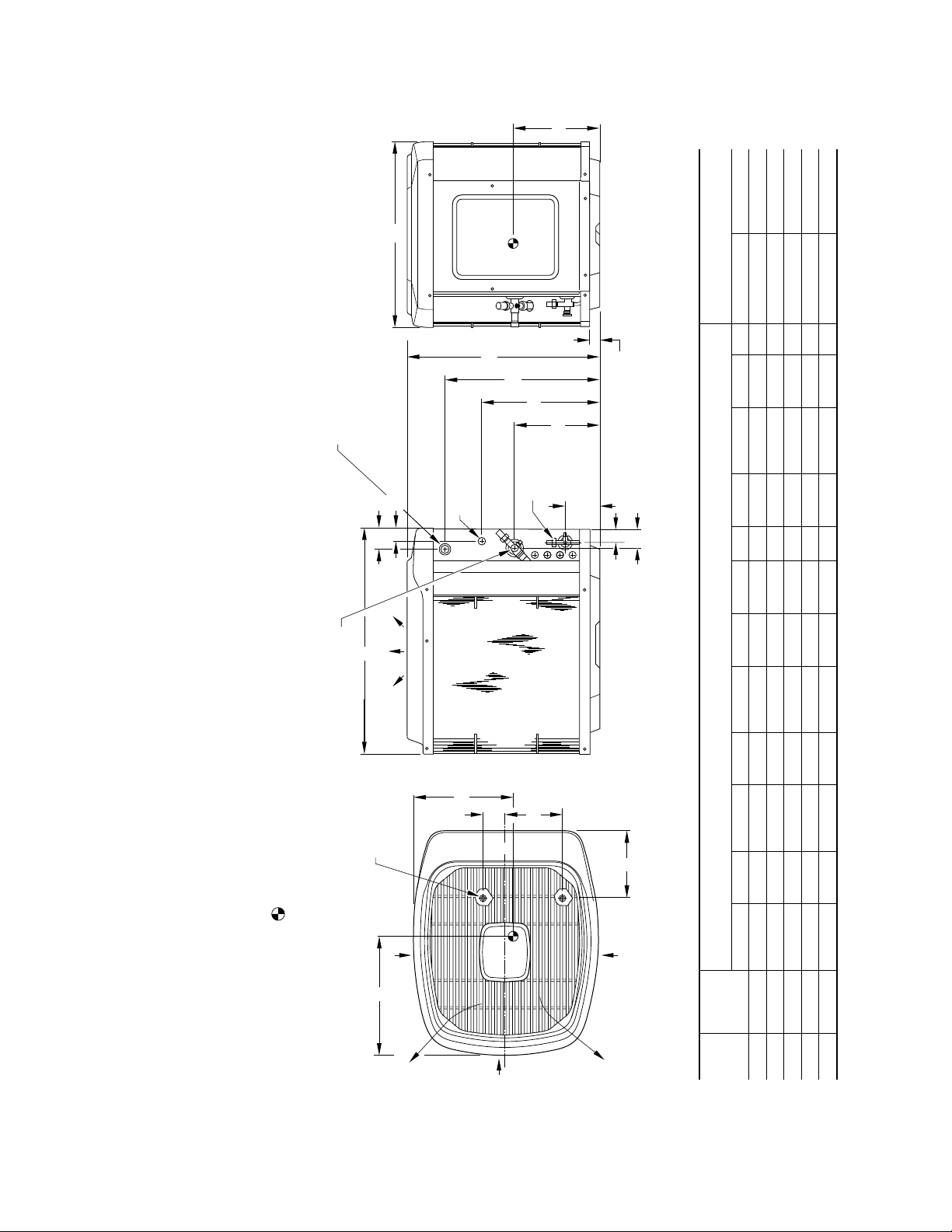
→ Dimensions (In.)
UNIT DIMENSIONS
Fig. 2—Unit Reference Drawing
/8 IN. DIA TIEDOWN
3
KNOCKOUTS (2)
PLACES IN BASEPAN
clearance to service side of unit, 48 in. above unit, 6 in.
AIR IN
L
C
L
on one side, 12 in. on remaining side, and 24 in. between units for proper airflow.
Minimum outdoor operating ambient in cooling mode is 55°F (unless low ambient control is used) max 125°F.2.
Maximum outdoor operating ambient in heating mode is 66°F.3.
Series designation is the 13th position of the unit model number.4.
Center of gravity .5.
1. Allow 30 in.
NOTES:
AIR DISCHARGE
AIR IN
2
J
AIR IN
AIR DISCHARGE
A B C D E F G H J K L M Support Feet Snow Stand
SERIES
SIZE
UNIT
024 1 33-13/16 30 34-15/16 4 9-3/4 21-1/2 27-7/8 5/8 8-3/16 16-13/16 20-1/2 14 26 X 32 31 X 35
030 1 39-13/16 30 34-15/16 4 9-3/4 27-1/2 33-7/8 3/4 8-3/16 16-1/2 20-3/8 15 26 X 32 31 X 35
036 1 39-13/16 30 34-15/16 4 9-3/4 27-1/2 33-7/8 3/4 8-3/16 16-1/2 20-3/8 16 26 X 32 31 X 35
042 1 39-13/16 30 34-15/16 4 9-3/4 27-1/2 33-7/8 7/8 8-3/16 16-1/2 20-3/8 15 26 X 32 31 X 35
048 1 33-13/16 38-5/8 45 5-5/16 11-13/16 21-1/2 27-7/8 7/8 8-9/16 19-1/2 25-1/2 16 34 X 42 36 X 46
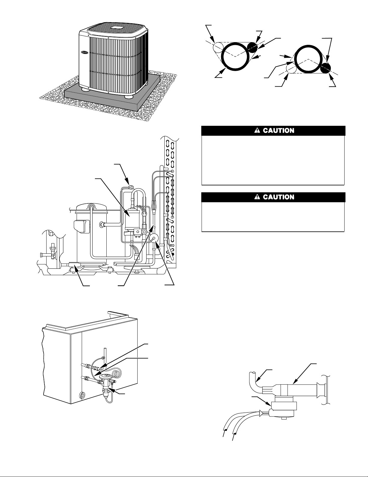
Fig. 3—Accessory Heat Pump Feet
SENSING BULB
DISCHARGE
MUFFLER
A96419
10 O'CLOCK
2 O'CLOCK
SENSING BULB
STRAP
SUCTION TUBE
4 O'CLOCK
7⁄
8
IN. OD
A81032
7
⁄
IN. OD & SMALLER
8
8 O'CLOCK
LARGER THAN
Fig. 6—Positioning of Sensing Bulb
DO NOT BURY MORE THAN 36 IN. OF REFRIGERANT
TUBING IN GROUND. If any section of tubing is buried,
there must be a 6-in. vertical rise to the valve connections on
the outdoor unit. If more than the recommended length is
buried, refrigerant may migrate to cooler buried section
during extended periods of unit shutdown, causing refrigerant
slugging and possible compressor damage at start-up.
STRAINER
TXVTXV
Fig. 4—TXV Location on Outdoor Section
COIL
SENSING
BULB
EQUALIZER
TUBE
A96433
Due to system design, this unit must be installed with a
factory-listed indoor section. Non-approved coils could cause
performance and reliability problems. Refer to pre-sale literature for approved indoor sections.
Step 5—Check Defrost Thermostat
Check defrost thermostat to ensure it is properly located and
securely attached. There is a liquid header with a brass distributor
and feeder tube going into the outdoor coil. At the end of 1 of the
feeder tubes there is a 3/8-in. OD stub tube approximately 3-in.
long. (See Fig. 7.)
The defrost thermostat should be located on the stub tube. Note
that there is only 1 stub tube used with the liquid header and on
most units it will be the bottom circuit.
Step 6—Make Piping Connections
Outdoor units may be connected to indoor sections using service
parts tubing package or field-supplied refrigerant grade tubing of
correct size and condition. For tubing requirements beyond 50 ft,
substantial capacity and performance losses can occur. Following
the Long-Line Application Guideline, which is available from your
local distributor, will reduce these losses and improve system
reliability. Refer to Fig. 8 for field tubing equivalent line length.
STUB
FEEDER
TUBE
TUBE
THERMOSTATIC
EXPANSION
VALVE
A88382
Fig. 5—Typical TXV Installation on Indoor Section
DEFROST
THERMOSTAT
A96527
Fig. 7—Defrost Thermostat Location
3
90° STD
OUTDOOR
WALL
CAULK
INDOOR WALL
NOTE:
AVOID CONTACT BETWEEN TUBING AND STRUCTURE
VAPOR TUBE
LIQUID TUBE
LIQUID TUBE
THROUGH THE WALL
JOIST
HANGER STRAP
(AROUND VAPOR
TUBE ONLY)
VAPOR TUBE
INSULATION
INSULATION
1
″
MIN
SUSPENSION
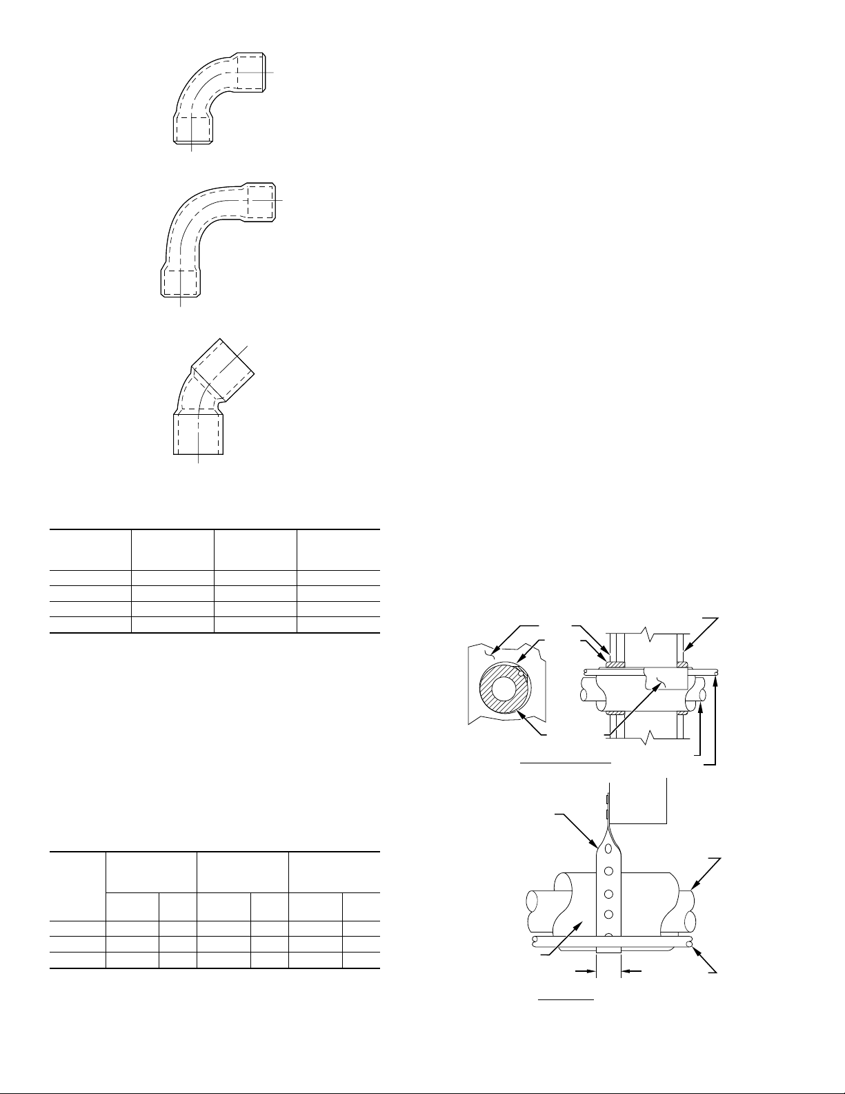
90° LONG RAD
45° STD
Fitting Losses in Equivalent Ft
TUBE
SIZE
OD (IN.)
5/8 1.6 1.0 0.8
3/4 1.8 1.2 0.9
7/8 2.0 1.4 1.0
1-1/8 2.6 1.7 1.3
90˚ STD
FIG. 8-A
Fig. 8—Tube Bend Losses for Long Lines
NOTE: In some cases noise in the living area has been traced to
gas pulsations from improper installation of equipment.
INSTALLATION RECOMMENDATIONS
1. Locate unit away from windows, or areas where unit operating
sounds may disturb customer.
2. Ensure that vapor and liquid tube diameters are appropriate to
capacity of unit. (See Table 1.)
A
B
C
90˚ L.R.
FIG. 8-B
4. Leave some slack between structure and unit to absorb
vibration.
5. When passing refrigerant tubes through wall, seal opening
with RTV or other pliable silicon-based caulk. (See Fig. 9.)
6. Avoid direct lineset contact with water pipes, ductwork, floor
joists, wall studs, floors, and walls.
7. Do not suspend refrigerant tubing from joists and studs with a
rigid wire or strap which comes in direct contact with tubing.
(See Fig. 9.)
8. Ensure that tubing insulation is pliable and it completely
surrounds vapor tube.
9. When necessary, use hanger straps which are 1 in. wide and
conform to shape of tubing insulation. (See Fig. 9.)
10. Isolate hanger straps from insulation by using metal sleeves
bent to conform to shape of insulation.
If refrigerant tubes or indoor coil is exposed to atmospheric
conditions for longer than 5 minutes, it must be evacuated to 500
microns to eliminate contamination and moisture in the system.
OUTDOOR UNITS CONNECTED TO FACTORY-APPROVED
INDOOR UNITS — Outdoor unit contains correct system refrigerant charge for operation with indoor approved unit when
connected by 15 ft of field-supplied or factory accessory tubing.
Check refrigerant charge for maximum efficiency. (See Step
10—Checking Charge.)
REFRIGERANT TUBING — Connect tubing to fittings on outdoor unit vapor- and liquid-service valves. (See Fig. 2.)
A92498
45˚ STD
FIG. 8-C
→ Table 1—Refrigerant Connections and
Recommended Liquid- and Vapor-Tube Diameters
UNIT
SIZE
LIQUID (IN.) VAPOR (IN.)
Connect
Dia
Tube
Dia
Connect
Dia
Tube
Dia
(LONG LINE)
Connect
024 3/8 3/8 5/8 5/8 5/8 3/4
030, 036 3/8 3/8 3/4 3/4 3/4 7/8
042, 048 3/8 3/8 7/8 7/8 7/8 7/8
Note: Tube diameters are for lengths up to 50 ft. For tubing lengths greater
than 50 ft, consult Long-Line Application Guideline.
3. Run refrigerant tubes as directly as possible by avoiding
unnecessary turns and bends.
VAPOR
(IN.)
Dia
Tube
Dia
A92469
Fig. 9—Piping Installation
4
 Loading...