

Page 1
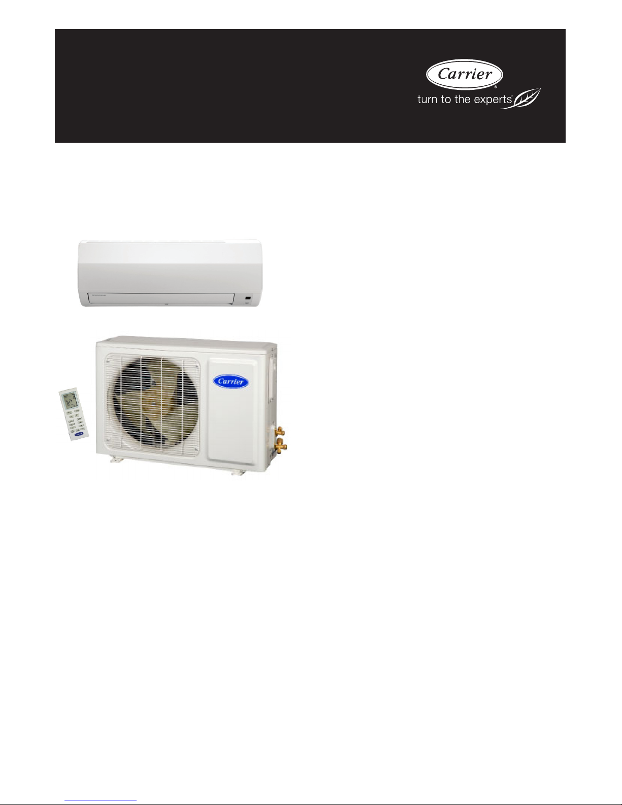
40GVC / 38GVC
40GVQ / 38GVQ
High---Wall Ductless Split Systems
Size 009K --- 036K
Product Data
INDUSTRY LEADING
FEATURES / BENEFITS
AN INEXPENSIVE AND CREATIVE
SOLUTION TO DESIGN PROBLEMS.
The 38GVC(Q)/40GVC(Q) inverter driven ductless split systems
are a matched combination of an outdoor condensing unit and an
indoor fan coil unit connected only by refrigerant tubing and wires.
The fan coil is mounted on the wall, near the ceiling. This selection
of fan coils permits inexpensive and creative solutions to design
problems such as:
S Add--on to current space (sun room)
The ideal compliment to your ducted system when it is impractical
or prohibitively expensive to use ductwork.
S Special space requirements
S When adding air conditioning to spaces that are heated
by hydronic or electric heat and have no ductwork.
S Historical renovations or any application where
preserving the look of the original structure is essential.
These compact indoor fan coil units take up very little space in the
room and do not obstruct windows. The fan coils are attractively
styled to blend with most room decors. Advanced system
components incorporate innovative technology to provide reliable
cooling performance at low sound levels.
Page 2

INVERTER TECHNOLOGY -- COMFORT
The inverter driven compressor is designed to run at various input
power frequencies (Hz) which controls the motor speed of the
compressor.
Even Temperature – The control package, including the inverter,
monitors outdoor and indoor temperatures as they relate to the
selected indoor set point and adjusts the speed of the compressor to
match the load and keep the system operating continuously rather
than cycling and creating temperature swings. This translates to
higher comfort levels for the occupants.
Rapid Pull Down/Warm--Up – Comfort is increased by the
ability to the inverter system to ramp up the compressor speed
enabling the system to reach the user selected room temperature set
point quicker.
Humidity Control – Running the system for longer periods and
continuously varying the compressor speed will enhance the
humidity control.
INDIVIDUAL ROOM COMFORT
Maximum comfort is provided because each space can be
controlled individually based on the usage pattern. The air sweep
feature provided permits optimal room mixing to eliminate hot and
cold spots for the occupant comfort.
38/40GVC(Q)
LOW SOUND LEVELS
When noise is a concern, the ductless split systems are the answer.
The indoor units are whisper quiet. There are no compressors
indoors, either in the conditioned space or directly over it, and
there is none of the noise usually generated by air being forced
through ductwork.
When sound ordinances and proximity to neighbors demand quiet
operation, the 38GVC(Q) unit is the right choice. With the inverter
technology, these units run at lower speeds most of the time
resulting in reduced sound levels.
INVERTER TECHNOLOGY – ENHANCED
ECONOMICAL OPERATION
Ductless systems are inherently economical to operate. Individual
rooms are heated or cooled only when required, and since the air is
delivered directly to the space, there is no need to use additional
energy to move the air in the ductwork. This economical operation
is enhanced further when the inverter system output matches the
load resulting in a more efficient system.
EASY--TO--USE CONTROLS
The high--wall systems have microprocessor--based controls to
provide the ultimate in comfort and efficiency. The user friendly
wireless remote control provides the interface between the user and
the unit.
FAST INSTALLATION
This compact ductless split system is simple to install. A mounting
bracket is standard with the indoor units and only wires and piping
need to be run between the indoor and outdoor units. These units
are fast and easy to install ensuring minimal disruption to
customers in homes or workplace. This makes the 38/40GVC(Q)
systems the equipment of choice for retrofit applications.
SIMPLE SERVICING AND
MAINTENANCE
Removing the top panel on outdoor units provides immediate
access to the control compartment, providing a service technician
access to check unit operation. In addition, the draw--thru design of
the outdoor section means that dirt accumulates on the outside
surface of the coil. Coils can be cleaned quickly from the inside
using a pressure hose and detergent.
On all indoor units, service and maintenance expense is reduced
due to easy--to--use cleanable filters. In addition, these high wall
systems have extensive self--diagnostics to assist in
troubleshooting.
BUILT--IN RELIABILITY
ductless split system indoor and outdoor units are designed to
provide years of trouble--free operation.
Both the indoor and outdoor units are well protected. Whenever
the microprocessor detects abnormal conditions, the unit will stop
and an error code is displayed. For a complete list of abnormal
conditions that are detected refer to the Safety and Reliability
section in the Standard Features and Accessories on page 4.
Inverter systems provide additional reliability due to soft start. This
refers to the ability of the inverter to start the compressor motor
using reduced voltage and reduced current. This feature is
beneficial from an electrical standpoint (eliminates current spikes)
as well as an overall reliability standpoint due to reduced stress on
all associated system components.
ACCESSORIES
A condensate pump accessory is available to provide installation
flexibility for those applications where gravity cannot be used to
dispose of the condensate.
A wired controller is available on sizes 30k and 36k units.
AGENCY LISTINGS
All systems are listed with AHRI (Air conditioning, Heating, and
Refrigeration Institute) and are ETL certified per UL 1995
standard.
SECURE OPERATION
If security is an issue, outdoor and indoor units are connected only
by refrigerant piping and wiring to prevent intruders from crawling
through ductwork or wall openings. In addition since the
38GVC(Q) can be installed close to an outside wall, coils are
protected from vandals and severe weather.
2
Page 3
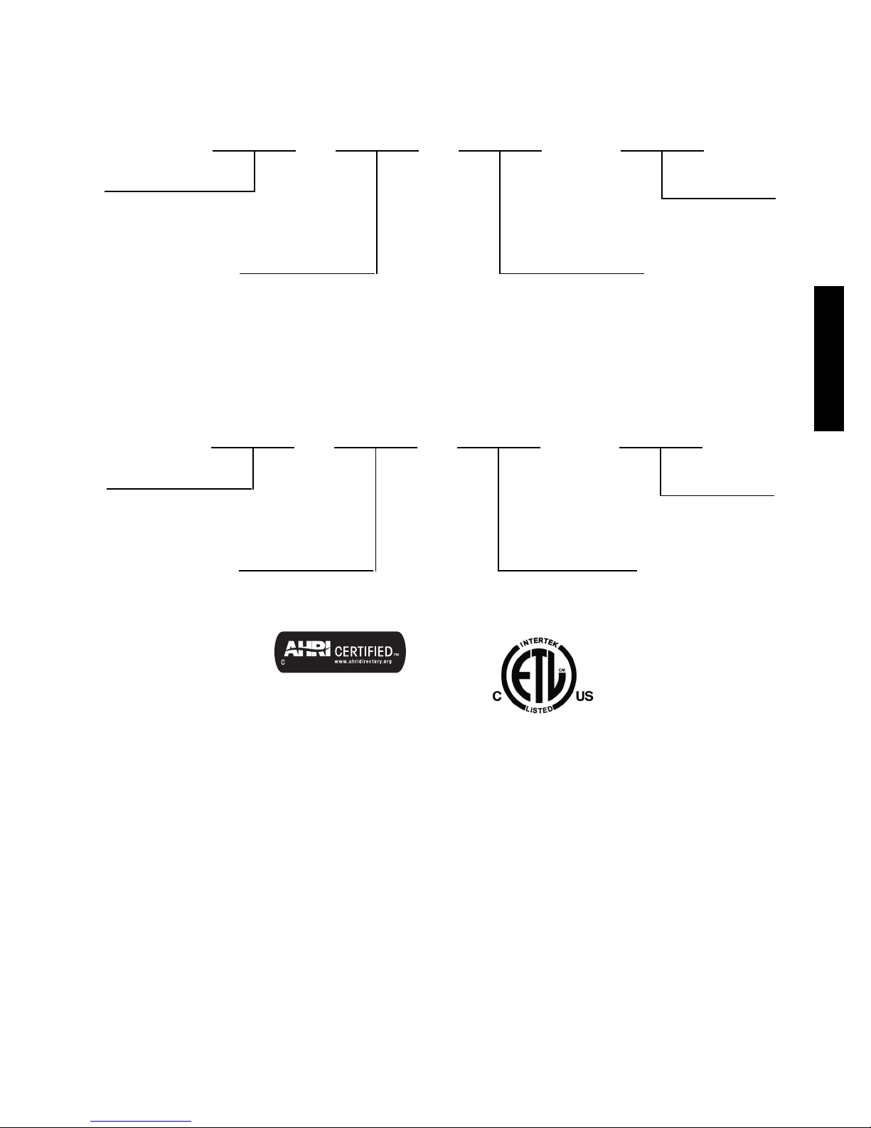
MODEL NUMBER NOMENCLATURE
INDOOR UNIT
40 GVQ
Fan Coil Unit
Unit Type
GVC --- C o o l ing On l y
GVQ --- Heat Pu m p
009
Nominal Capacity
009 --- 3 / 4 To n
012 --- 1 To n
018 --- 1 --- 1 / 2 To n
024 --- 2 To n
030 --- 2 --- 1 / 2 To n ( H P o n l y )
036 --- 3 To n
--- --- ---
1
Volt age
1 --- 1 1 5 --- 1 --- 6 0
3 --- 208/230--- 1--- 60
Air---Cooled C ondenser
OUTDOOR UNIT
38 GVQ 1
Unit Type
GVC --- C o o l i n g On ly
GVQ --- H e a t Pump
Use of the AHRI Certified
TM Mark indicates a
manufacturer’s
participation in the
program For verification
of certification for individual
products, go to
www.ahridirectory.org.
009
Nominal Capacity
009 --- 3 / 4 To n
012 --- 1 To n
018 --- 1 --- 1 / 2 To n
024 --- 2 To n
030 --- 2 --- 1 / 2 To n ( H P o n l y )
036 --- 3 To n
--- --- ---
Volt age
1 --- 1 1 5 --- 1 --- 6 0
3 --- 208/230--- 1--- 60
38/40GVC(Q)
3
Page 4
STANDARD FEATURES AND ACCESSORIES
Ease Of Installation
Mounting Brackets S
Low Voltage Controls S
Comfort Features
Microprocessor Controls S
Wireless Remote Control S
Rapid Cooling/Heating S
Automatic Air Sweep S
Cold Blow Prevention S
Continuous Fan * S
Auto Restart Feature S
Memory Function S
Auto Changeover on Heat Pumps S
Dry Function S
Energy Saving Features
Inverter Driven Compressor S
Sleep Mode S
24 Hour Stop/Start Timer S
Safety And Reliability
Indoor Unit Freeze Protection S
3MinuteCompressorTimeDelay S
High Compressor Discharge Temperature S
Low Voltage Protection S
Compressor Overload Protection S
38/40GVC(Q)
Compressor Over current Protection S
IPM Module Protection S
Ease Of Service And Maintenance
Cleanable Filters S
Diagnostic LED’s On Outdoor Board S
Error Messages Displayed Front Panel S
Application Flexibility
Condensate Pump A
Standard Warranty
7 Year Compressor Limited Warranty** S
5 Year Parts Limited Warranty** S
Legend
S Standard
A Accessory
O Optional
F Field Fabricated
* Cooling Only
** For owner occupied residential applications.
For Commercial applications, warranty is 1 year parts and 5 years
compresso r.
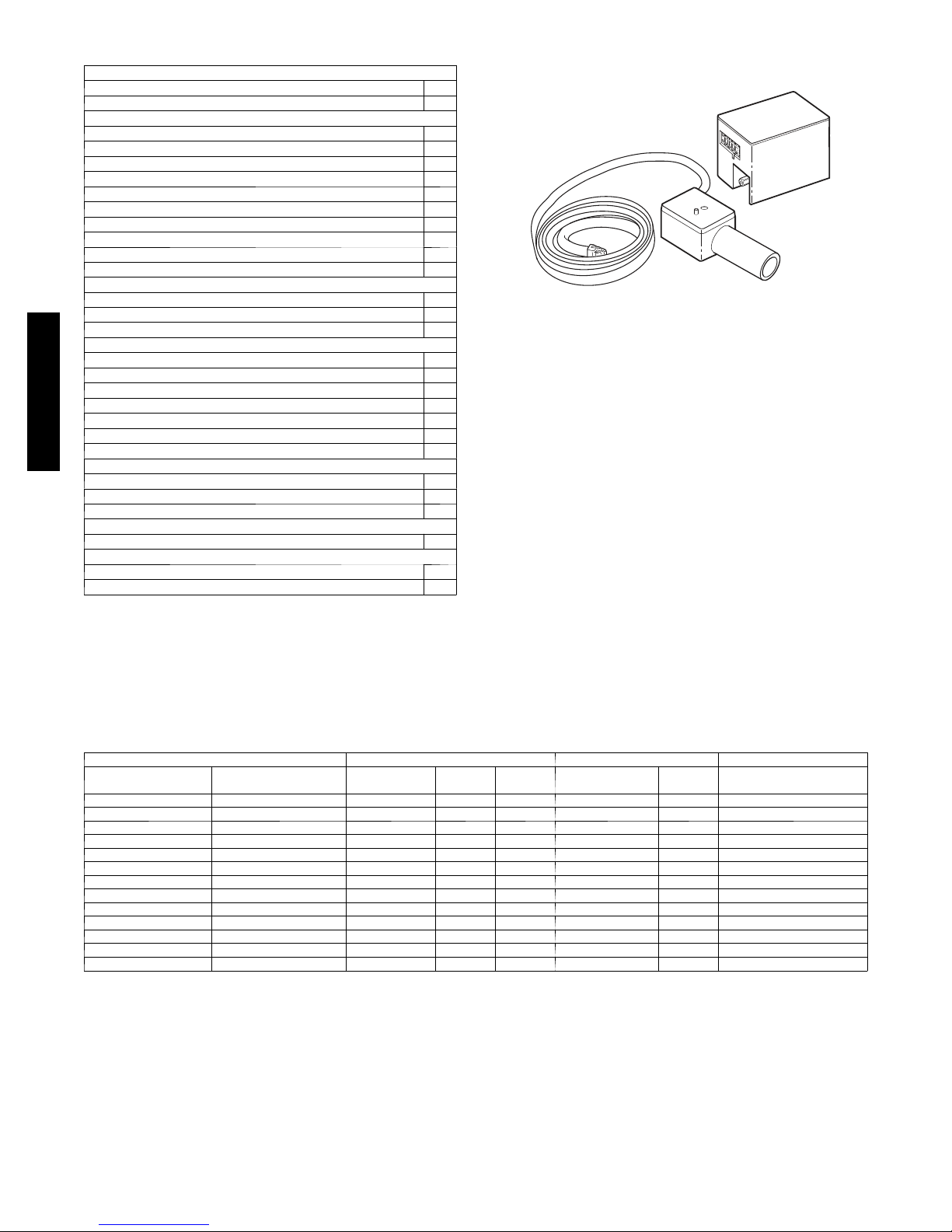
INDOOR UNITS
A07892
Fig. 1 – Condensate Pump Accessory
On high wall fan coils, the condensate pump accessory is
recommended when adequate drain line pitch cannot be provided,
or when the condensate must move up to exit.
The pump has a lift capability of 12 ft (3.6 m) on the discharge side
if the pump is mounted in the fan coil or 6 ft (1.8 m) on the suction
side if the pump is remote mounted.
AHRI* CAPACITY RATINGS
Model Numbers Cooling High Heating 47° F Low Heating 17° F
Outdoor Unit Indoor Unit
3 8 GVC009 --- --- --- 1 4 0 GVC009 --- --- --- 1 9,000 12.0 16.0 --- --- --3 8 GVC012 --- --- --- 1 4 0 GVC012 --- --- --- 1 11,800 9.4 16.0 --- --- --3 8 GVC012 --- --- --- 3 4 0 GVC012 --- --- --- 3 12,000 9.8 16.0 --- --- --3 8 GVC018 --- --- --- 3 4 0 GVC018 --- --- --- 3 18,000 11.1 16.0 --- --- --3 8 GVC024 --- --- --- 3 4 0 GVC024 --- --- --- 3 22,000 10.0 16.0 --- --- --3 8 GVC036 --- --- --- 3 4 0 GVC036 --- --- --- 3 33,600 8.2 16.0 --- --- --3 8 GVQ0 0 9 --- --- --- 1 40 G V Q 0 0 9 --- --- --- 1 9,000 12.0 16.0 10,000 8.6 5,400
3 8 GVQ0 1 2 --- --- --- 1 40 G V Q 0 1 2 --- --- --- 1 11,800 9.4 16.0 13,000 8.6 8,500
3 8 GVQ0 1 2 --- --- --- 3 40 G V Q 0 1 2 --- --- --- 3 12,000 9.8 16.0 12,000 8.5 6,800
3 8 GVQ0 1 8 --- --- --- 3 40 G V Q 0 1 8 --- --- --- 3 18,000 11.1 16.0 19,200 8.0 12,000
3 8 GVQ0 2 4 --- --- --- 3 40 G V Q 0 2 4 --- --- --- 3 22,000 10.0 16.0 26,600 9.5 18,600
3 8 GVQ0 3 0 --- --- --- 3 40 G V Q 0 3 0 --- --- --- 3 28,000 9.3 16.0 30,600 8.2 18,400
3 8 GVQ0 3 6 --- --- --- 3 40 G V Q 0 3 6 --- --- --- 3 33,600 8.2 16.0 36,400 8.2 20,600
*Air Conditioning, Heating & Refrigeration Institute
--- = N / A
Legend
HSPF --- Heating Seasonal Performance Factor
SEER --- Seasonal Energy Efficiency Ratio
NOTES:
1. Ratings are net values reflecting the effects of circulating fan heat. Ratings are based on: Cooling Standard: 80_F (26.67_C) db, 67_F (19.44_C) wb air
entering indoor unit and 95_F(35_C) db air entering outdoor unit. High Temperature Heating Standard: 70_F (21.11_C) db air entering indoor unit and 47_F
(8.33_C) db, 43_F (6.11_C) wb air entering outdoor unit.
2. Ratings are based on 25 ft. (7.62 m) of interconnecting refrigerant lines.
3. All system ratings are based on fan coil units operating at high fan speed. Consult Physical Data tables for air flows at all available fan speeds.
Capacity
(Btuh)
EER SEER Capacity (Btuh) HSPF Capacity (Btuh)
4
Page 5
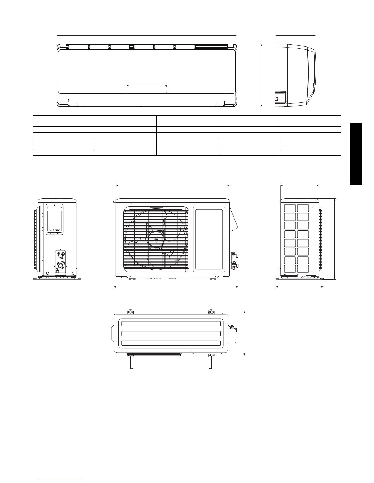
DIMENSIONS -- INDOOR
Unit Size
9K 30.3 (770) 11.1 (283) 7.9 (201) 18.7 (8.5)
12 K 30.3 (770) 11.1 (283) 7.9 (201) 19.8 ( 9.0)
18 K 34.0 (865) 12.0 (305) 8.5 (215) 26.4 (12)
24 K 39.7 (1008) 12.6 (319) 8.7 (221) 33.1 (15.0)
30/36 K 53.1 (1349) 12.8 (325) 10.0 (254) 44.1 (20.0)
W
In. (mm)
WD
H
A12377
H
In. (mm)
D
In. (mm)
Net Operating Weight
Lbs. (Kg)
Fig. 2 – Indoor Unit Dimensions
DIMENSIONS -- OUTDOOR
Unit: IN. (mm)
30.0 (762)
33.4 (848)
38/40GVC(Q)
10.1 (257)
21.3 (540)
12.6 (320)
11.7 (267)
Fig. 3 – 9K and 12K 115V (Net Operating Weight: 75 lbs. / 34 kg)
21.3 (540)
A12531
5
Page 6
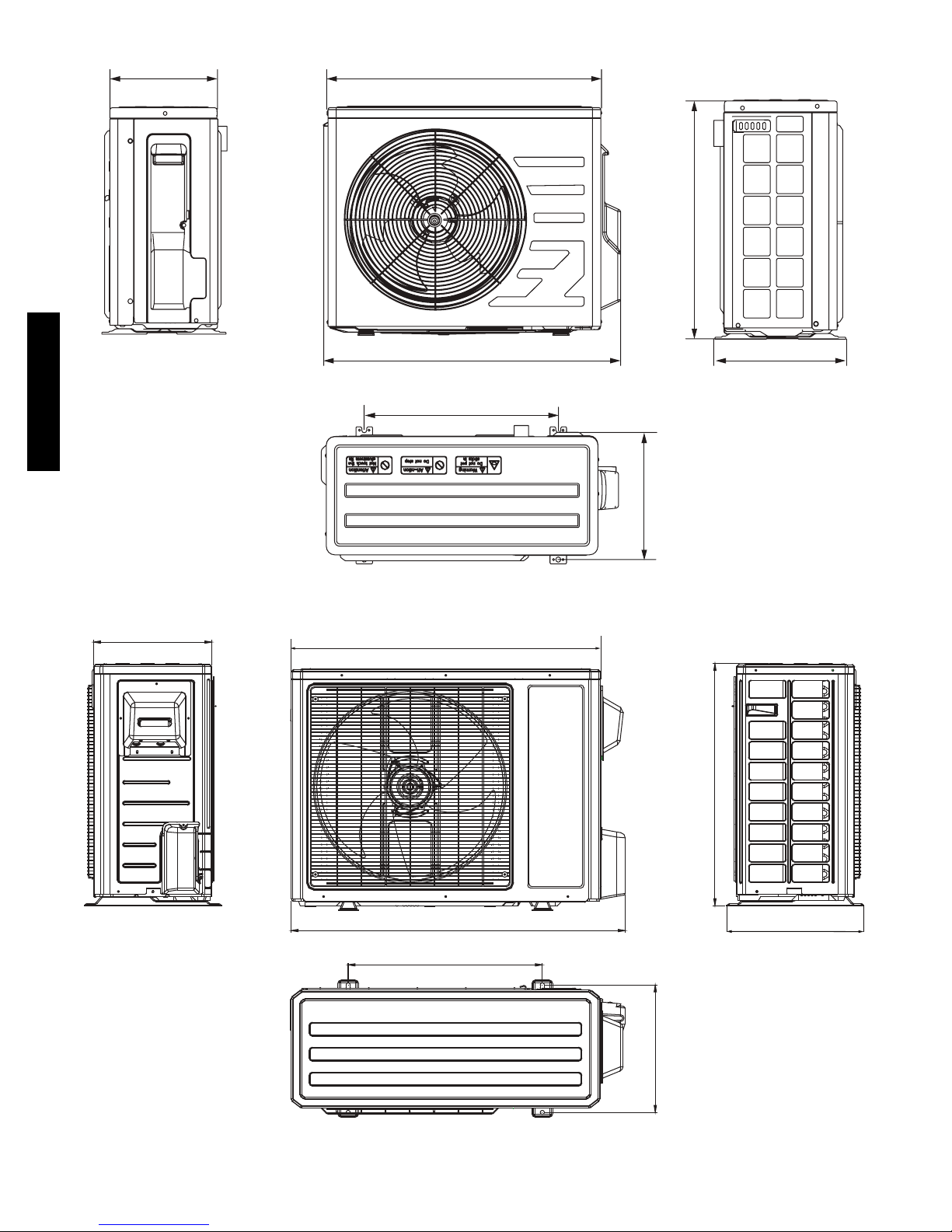
DIMENSIONS -- OUTDOOR CONTINUED
10.8 (274)
25.9 (658)
21.7 (551)
28.0 (711)
18.5 (470)
38/40GVC(Q)
Unit: IN. (mm)
Unit: IN. (mm)
11.8 (300)
12.5 (318)
A12532
Fig. 4 – 12K 230V (Net Operating Weight: 63.8 lbs. / 30 kg)
13.4 (340)
35.0 (890)
Unit: IN. (mm)
Fig. 5 – 18K and 24K (Net Operating Weight: 112.2 lbs. / 51 kg)
37.9 (963)
22.0 (560)
27.6 (700)
15.6 (396)
14.3 (364)
A12533
6
Page 7
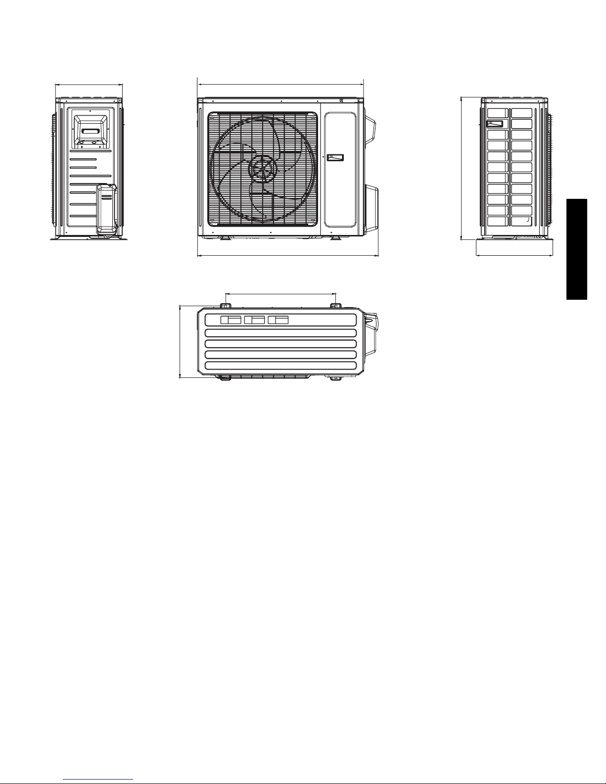
DIMENSIONS -- OUTDOOR CONTINUED
14.6
(370.8)
(398.8)
15.7
36
(914.4)
38.6
(980.4)
24
(609.6)
(789.9)
31.1
16.7
(424.2)
38/40GVC(Q)
in. (mm)
A12379
Fig. 6 – 30K and 36K (Net Operating Weight: 30K = 154 lbs. / 70 kg; 36K = 161 lbs. / 73 kg)
7
Page 8
CLEARANCES
Indoor Unit
Distance to Ceiling
6 in (152 mm)
Distance to Wall
6 in (152 mm)
Distance to Wall
6 in (152 mm)
NOTE: Refrigerant lines
may be routed in any of the
(4) directions, right,
right rear, left, or left rear.
Distance in Front of Unit
118 in (2997 mm)
Distance to Floor
66 in (1676 mm)
See instructions for details
38/40GVC(Q)
●
The clearance dimensions are necessary for a correct installation
and are the minimum permissible distances to adjacent structures.
Outdoor Unit
Distance to
Back Wall
12 in (305 mm)
Above Unit
20 in (508 mm)
Air Discharge Side
79 in (2007 mm)
Fig. 7 – Indoor and Outdoor Unit Clearances
8
Air Inlet Side
12 in (305 mm)
Distance to Wall
20 in (508 mm)
valve cover
A12385
Page 9
PHYSICAL DATA -- 38GVC
Outdoor Unit 38GVC 009 012 012 018 024 036
System Voltage 1 1 5 --- 1 --- 6 0 208/230---1--- 60
Control Voltage Low Voltage Pulse DC
Rated Cooling Capacity (Btuh) 9,000 11,800 12,000 18,000 22,000 33,600
Cooling. Capacity Range
Min --- Max (Btuh)
Operating Weight lb. (kg) 75 (34) 63.8 (30) 112.2 (51) 161 (73)
Refrigerant Type R--- 410A
Metering Device @ Outdoor Unit Cap. Tube EXV Cap. Tube
Charge lb. (kg) 2.3 (1.05) 2.8 (1.27) 2.2 (1.0) 2.8 (1.27) 3.4 (1.55) 5.3 (2.4)
Compressor
Type Twin Rotary Inverter Driven
Model KNB092FHBMC QXA---B096ZC190 SNB130FGYMC C---6RZ146H1A TNB306FPGMC
Outdoor Fan
CFM 1060 942 1880 1880 2590
RPM 850 880 690 690 900
Diameter (in) 15.7 14.6 20.5 20.5 21.7
Watts 30 21 60 170
Outdoor Coil
Face Area (sq.) 4.4 3.7 5.9 6.1 7.7
No. Rows 2
Fins per inch 16 18
Refrigerant Lines
Connection Type Flare
Liquid (Mix Phase) in OD 1/4”
Vapor Line in OD 3/8” 1/2” 5/8”
Maximum Length ft. 50 65 50 82 98
Max Lift (Fan Coil Above) ft. 33
Max Drop (Fan Coil Below) ft. 33
External Finish White
3,500 --- 11,000 3,300 --- 12,500 3,300 --- 12,500 4,500 --- 21,000 6,400 --- 24,000 7,400 --- 36,000
38/40GVC(Q)
9
Page 10
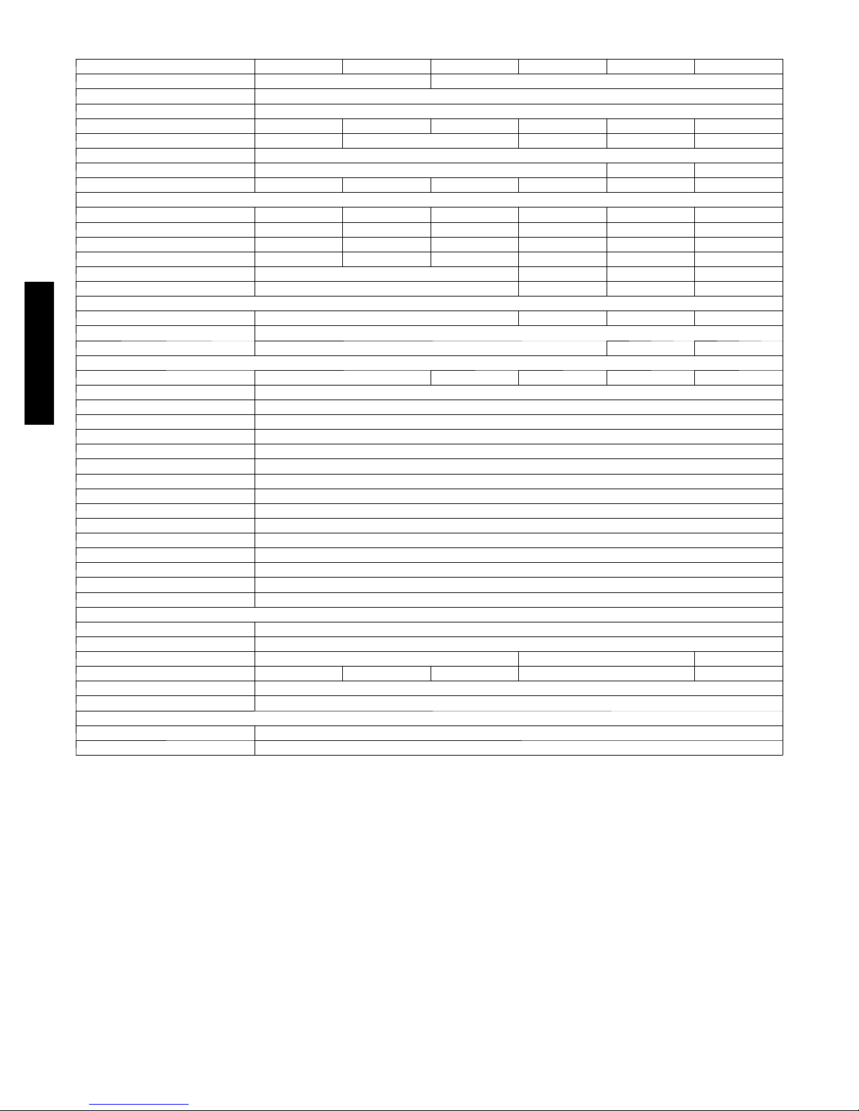
PHYSICAL DATA CONTINUED -- 40GVC
Indoor Unit 40GVC 009 012 012 018 024 036
System Voltage 115 V 208/230 ---1---60
Control Voltage Low Voltage Pulse DC
Electrical Connections Indoor Unit Powered From Outdoor Unit
Rated Cooling Capacity (Btuh) 9,000 11,800 12,000 18,000 22,000 33,600
Operating Weight lb. (kg) 18.7 (8.5) 19.8 (9.0) 26.5 (12.0) 33.1 (15.0) 44.1 (20)
Refrigerant Type R--- 410A
Metering Device @ Outdoor Unit Cap. Tube EXV Cap. Tube
Moisture Removal Rate (pints/hr.) 1.7 2.9 2.9 3.8 4.5 7.4
Indoor Fan
R PM/C F M ( T u r bo) --- C o o l i n g 1300/330 1350/341 1350/341 1400/471 1350/588 ---
R PM/C F M ( H i g h ) --- C o o l i n g 1100/277 1150/288 1150/288 1150/400 1150/471 1550/824
RPM/CFM (Medium) --- Cooling 900/224 950/235 950/235 1000/330 1000/412 1400/706
RPM/CFM (Low) --- Cooling 700/188 750/200 750/200 850/271 850/353 1300/677
Motor Watts 15 20 35 60
Blower Quantity … Size (DxL) in 1 … 3.62 x 23.4 1 … 3.9 x 25.6 1 … 3.9 x 30.1 2 … 4.25 x 20.6
Indoor Coil
Face Area (sq.) 1.93 2.2 2.8 4.4
No. Of Rows 2
Fins Per Inch 18 17 18
Filters
Quantity 2 2 2 2 2
Controls Integrated Microprocessor
38/40GVC(Q)
Wireless Remote Standard
Modes Cool/Heat/Dry/Auto
Fan Mode High/Medium/Low/Auto
Emergency Mode Ye s
Defrost Method Demand Defrost
Diagnostics Ye s
Air S weep Ye s
Soft Start Ye s
Rapid Cooling/Heating Ye s
Cold Blow Prevention Ye s
Sleep Mode Ye s
24 Hour Timer Ye s
Auto Restart Yes
FreezeProtectionOnIndoorUnit Ye s
Refrigerant Lines
Connection Type Flare
Liquid (Mix Phase) in OD 1/4”
Vapor Line in OD 3/8” 1/2” 5/8”
Maximum Length ft. 50 65 50 82 98
Max Lift (Fan Coil Above) ft. 33
Max Drop (Fan Coil Below) ft. 33
Condensate Drain
Size in ID = 1/2” OD = 5/8”
External Finish White
10
Page 11
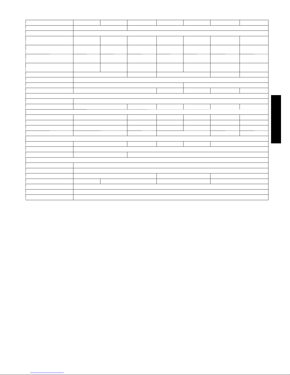
PHYSICAL DATA CONTINUED -- 38GVQ
Outdoor Unit 38GVQ 009 012 012 018 024 030 036
System Voltage 1 1 5 --- 1 --- 6 0 208/230--- 1 ---60
Control Voltage Low Voltage Pulse DC
Rated Cooling Capacity
(Btuh)
Cooling. Capacity Range
Min --- Max (Btuh)
Rated Heating Capacity
(Btuh)
Heating. Capacity Range
Min --- Max (Btuh)
Operating Weight lb (kg) 75 (34) 63.8 (30) 112.2 (51) 154 (70) 161 (73)
Refrigerant Type R --- 410A
Metering Device @ OD Unit Cap. Tube EXV
Charge lb (kg) 2.2 (1.0) 2.9 (1.3) 3.4 (1.55) 5.3 (2.4) 5.7 (2.6)
Compressor
Ty pe Twin Rotary Inverter Driven
Model KNB092FHBMC QXA--- B096ZC190 SNB130FGYMC C --- 6RZ146H1A QXAS---D23ZX090 TNB306FBGMC
Outdoor Fan
CFM 1060 942 1880 1880 2354 2590
RPM 850 880 690 690 830 900
Diameter (in) 15.7 14.6 20.5 20.5 21.7 21.7
Watts watts 30 21 60 100 170
Outdoor Coil
Face Are a (sq. ft) 4.4 3.7 5.9 6.1 7.7
No. Rows 2
Fins per inch 16 18
Refrigerant Lines
Connection Type Flare
Liquid (Mix Phase) in OD 1/4”
Vap or Li ne in OD 3/8” 1/2” 5/8”
Maximum Length ft 65 50 82 98
Max Lift (Fan Coil Above) ft 33
Max Drop (Fan Coil Below) ft 33
External Finish White
9,000 11,800 12,000 18,000 22,000 28,000 33,600
3,500 --- 11,000 3,300 --- 12,500 3,300 --- 12,500 4,500 --- 21,000 6,400 --- 24,000 9,500 --- 30,000 7,400 --- 36,000
10,000 13,000 12,000 19,200 26,600 30,600 36,400
2,500 --- 11,000 3,400 --- 13,500 3,400 --- 13,500 4,000 --- 23,000 4,100 --- 26,600 10,000 --- 33,000 15,000 --- 36,000
38/40GVC(Q)
11
Page 12
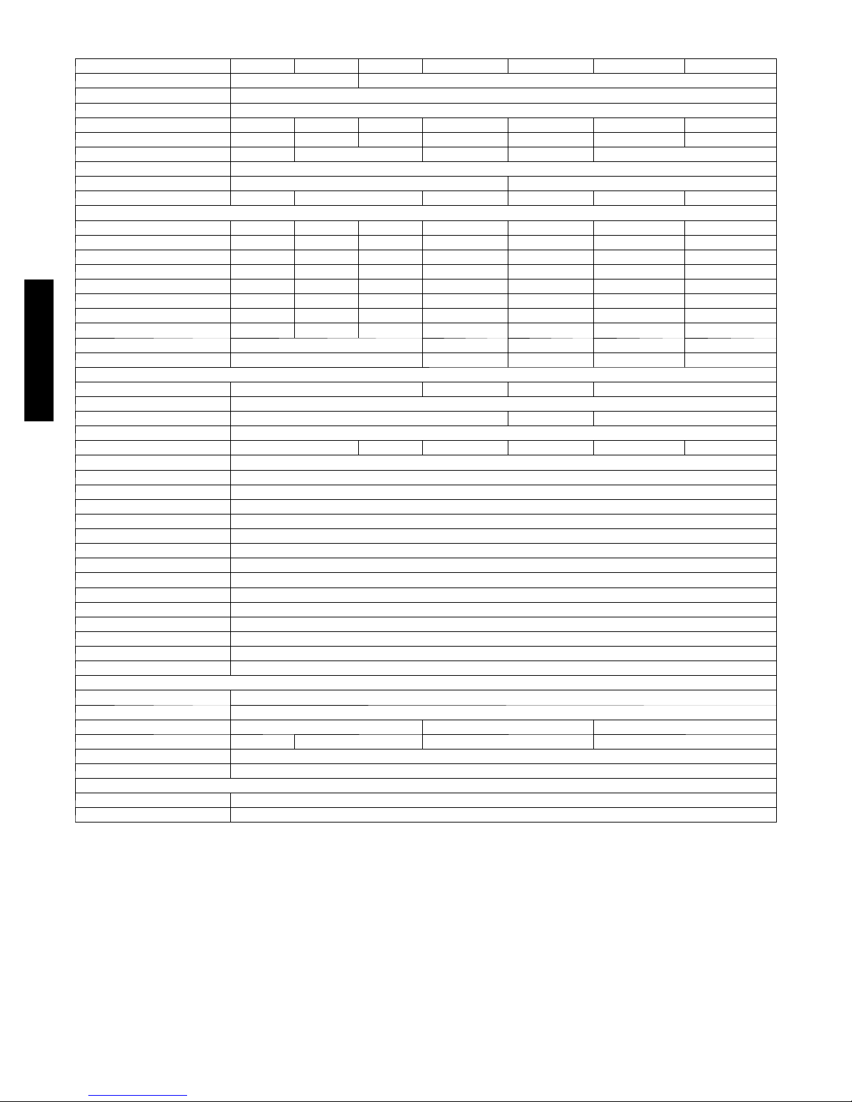
PHYSICAL DATA CONTINUED -- 40GVQ
Indoor Unit 40GVQ 009 012 012 018 024 030 036
System Voltage 115 V 208/230---1 --- 60
Control Voltage Low Voltage Pulse DC
Electrical Connections Indoor Unit Powered From Outdoor Unit
Rated Cooling Capacity (Btuh) 9,000 11,800 12,000 18,000 22,000 28,000 33,600
Rated Heating Capacity (Btuh) 10,000 13,000 12,000 19,200 26,600 30,600 36,400
Operating Weight lb (kg) 18.7 (8.5) 19.8 (9.0) 26.5 (12.0) 33.1 (15.0) 44.1 (20.0)
Refrigerant Type R--- 410A
Metering Device @ Outdoor Unit Cap. Tube EXV @ Outdoor Unit
Moisture Removal Rate(pints/hr) 1.7 2.9 3.8 4.2 6.3 7.4
Indoor Fan
RPM/CFM (Turbo) --- Cooling 1300/330 1350/341 1350/341 1400/471 1350/588 --- ---
R P M / C F M ( H i g h) --- C o o ling 1100/277 1150/288 1150/288 1150/400 1150/471 1410/706 1550/824
RPM/CFM (Medium) --- Cooling 900/224 950/235 950/235 1000/330 1000/412 1280/677 1400/706
R P M / C F M ( L o w ) --- C o o l i n g 700/188 750/200 750/200 850/271 850/353 1200/647 1300/677
R P M / C F M ( T urbo ) --- H e a t i n g 1300/330 1350/341 1350/341 1450/471 1350/588 --- ---
RPM/CFM (High) --- Heating 1150/277 1200/288 1200/288 1250/400 1150/471 1410/706 1550/824
RPM/CFM (Medium) --- Hea ting 980/224 1000/235 1000/235 1100/330 1000/412 1280/677 1400/706
R P M / C F M ( L o w ) --- H e a t i n g 820/188 850/200 850/200 950/271 900/353 1200/647 1300/677
Motor Watts 15 20 35 40 60
Blower Quantity … Size (DxL) in 1 … 3.62 x 23.4 1 … 3.9 x 25.6 1 … 3.9 x 30.1 2 … 4.25 x 20.6 2 … 4.25 x 20.6
Indoor Coil
38/40GVC(Q)
Face Are a (sq.ft) 1.93 2.2 4.2 4.4
No. Of Rows 2
Fins Per Inch 18 17 18
Filters
Quantity 2 2 2 2 2 2
Controls Integrated Microprocessor
Wireless Remote Standard
Modes Cool/Heat/Dry/Auto
Fan Mode High/Medium/Low/Auto
Emergency Mode Yes
Defrost Method Demand Defrost
Diagnostics Yes
Air Sweep Ye s
Soft Start Yes
Rapid Cooling/Heating Yes
Cold Blow Prevention Ye s
Sleep Mode Yes
24 H o ur Timer Ye s
Auto Restart Yes
Freeze ProtectionOnIndoorUnit Yes
Refrigerant Lines
Connection Type Flare
Liquid (Mix Phase) in OD 1/4”
Vap or Li ne in OD 3/8” 1/2” 5/8”
Maximum Length ft 65 50 82 98
Max Lift (Fan Coil Above) ft 33
Max Drop (Fan Coil Below) ft 33
Condensate Drain
Size in ID = 1/2” OD = 5/8”
External Finish White
12
Page 13
UNIT MOUNTING (INDOOR)
A
Mounting template – The fan coil units are furnished with
mounting bracket to hang the unit and mark the location of the
wiring, and refrigeration line hole locations.
Support – Adequate support must be provided to handle the
weight of all fan coils. Refer to the Physical Data section for
weights, and the base unit dimensional drawings for the location of
mounting bracket.
Unit Leveling – For reliable operation, units should be level in all
planes.
Clearances – Minimum clearance as shown in Fig. 7.
Unit location – Select a location which will provide the best air
circulation for the room. These units should be positioned as high
as possible on the wall for the best air circulation. The unit return
and discharge should not be obstructed by furniture, curtains, or
anything which may cause the unit to short cycle or air to recycle.
Place the unit in the middle of the selected wall (if possible). Use
an outside wall, if available, to make piping easier, and place the
unit so it faces the normal location of room occupants.
UNIT MOUNTING (OUTDOOR)
Support – A location which can bear the weight of outdoor unit.
Refer to the Physical Data section for weights, and base
dimensional drawings.
Unit Leveling – For reliable operation, units should be level in all
planes.
Clearances – Minimum clearances, as shown in Fig. 7, must be
provided for airflow. The outdoor units are designed for free--blow
applications. Air inlets and outlets should not be restricted.
Unit location – A location which is convenient to installation and
not exposed to strong wind. If unit is exposed to strong winds, it is
recommended that a wind baffle be used. Contact your Carrier
representative for drawings. Do not install the outdoor or indoor
units in a location with special environmental conditions.
SYSTEM OPERATING CONDITIONS
OPERATING RANGE
Unit Size
009
012 (115v)
012 (230v)
018
024 (AC)
024 (HP)
030
036 (AC)
036 (HP)
Cooling Outdoor Heating Outdoor
Min --- Max ° F (° C) Min --- Max ° F (° C)
64.4 --- 113
( 1 8 --- 4 5 )
5 --- 1 0 9
(---15 --- 42.8)
5 --- 1 1 8
(---15 --- 47.8)
5 --- 1 1 8
(---15 --- 47.8)
50 --- 118
(10 --- 47.8)
5 --- 1 0 9
(---15 --- 42.8)
64.4 --- 109
(18 --- 42.8)
5 --- 1 0 9
(---15 --- 42.8)
5 --- 7 5
(---15 --- 23.9)
19 --- 75
(---7.2 --- 23.9)
5 --- 7 5
(---15 --- 23.9)
17 --- 75
(---8.3 --- 23.9)
REFRIGERANT LINES
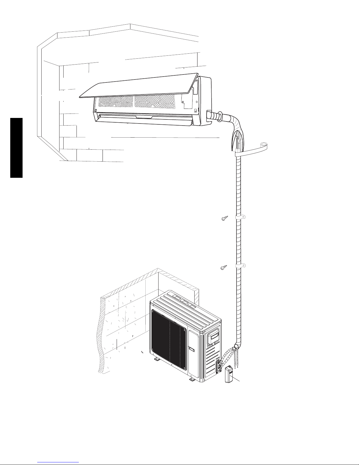
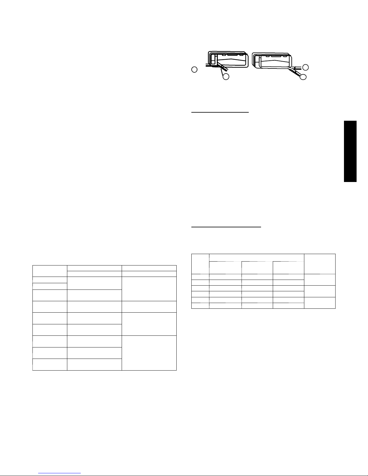
Routing – Refrigerant lines can be routed in any of the four
directions shown in Fig. 8.
sviewedfrom front
1
Right Exit
2
Right Rear Exit
(a)
(b)
Fig. 8 – Refrigerant Line Routing
General Guidelines:
1. The 38GVC(Q) units are shipped with full charge of
R--410A refrigerant. All charges, line sizing, and capacities
are based on runs of 25ft (7.6 m). For runs over 25ft (7.6
m), consult long line section for charge adjustments.
2. Refrigerant lines should not be buried in the ground. If it is
necessary to bury the lines, not more than 36 inches (914
mm) should be buried. Provide a minimum of 6 inch (152
mm) vertical rise to service valves to prevent refrigerant
migration.
3. Both lines must be insulated. Use a minimum of 1/2 inch
(12.7 mm) thick insulation. Closed--cell insulation is
recommended in all long--line applications.
4. Special consideration should be given to isolating
interconnecting tubing from the building structure. Isolate
the tubing so that vibration or noise is not transmitted into
the structure.
Long Line Applications:
1. No change in line sizing is required.
2. Add refrigerant per table below.
ADDITIONAL CHARGE TABLE
Unit
Size
009k 0.0 0.16 0.16
012k 0.0 0.16 0.22
018k 0.0 0.16 0.22
024k 0.0 0.16 0.22
030k 0.0 --- 0.54
036k 0.0 0.54 0.54
--- = N / A
3. Reduction in capacity due to long lines can be calculated
Additional Charge, oz./ft -- - ft. (m)
10 --- 25
(3.05 -- - 7.62)
> 25 (7.62)
Cooling
from the chart below.
> 25 (7.62)
Heat Pump
3LeftExit
Left Rear Exi
4
Max
Allowable
Length
ft. (m)
50 (15)
82 (25)
98 (30)
A08281
38/40GVC(Q)
METERING DEVICES
These units have either a capillary tube or a EXV in the outdoor
units as listed in the Physical Data tables.
13
Page 14
DRAIN CONNECTIONS
Install drains to meet the local sanitation codes. If adequate gravity
drainage cannot be provided, a field installed condensate pump
accessory should be used. For pump lift capability, please refer to
the Installation Instructions for the condensate pump accessory
(53DS--900------117 for 115v / 53DS--900------118 for 230v).
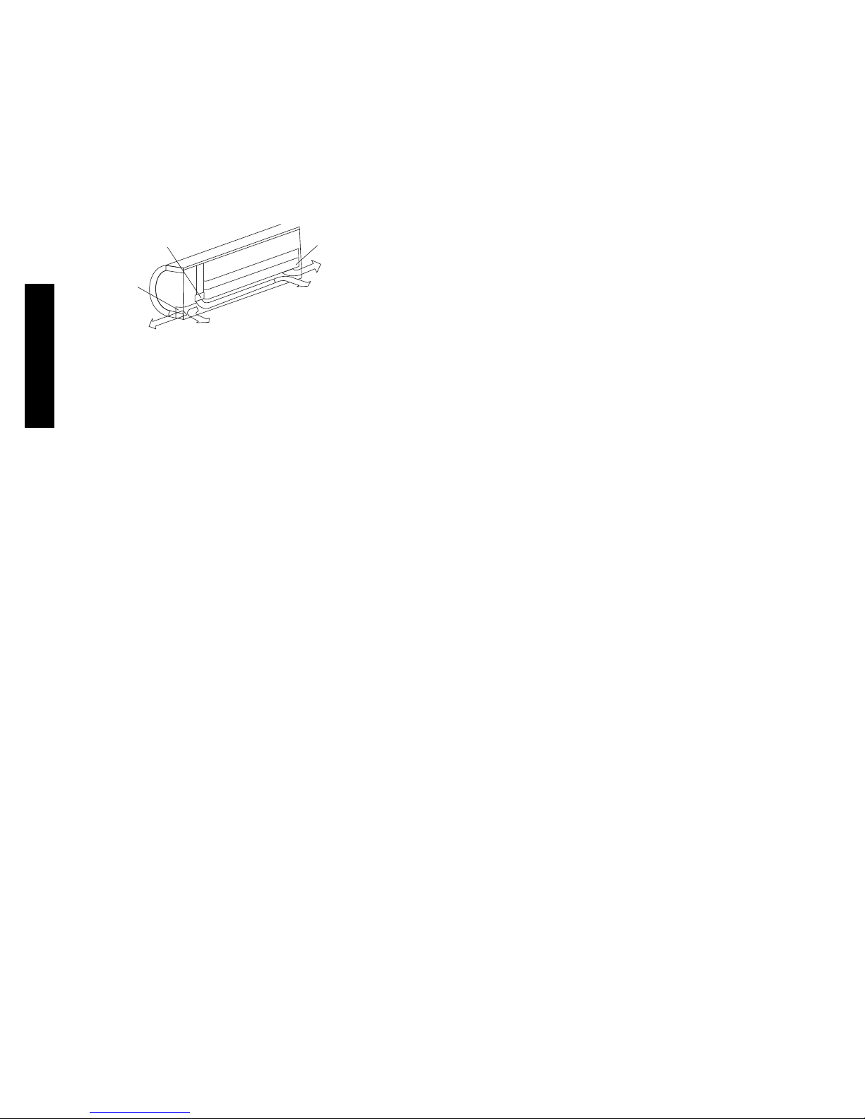
NOTE: The high wall fan coils have internal condensate trap. An
external trap is not required.
Drain connections may be routed through alternate locations as
showninFig.9.
Pipe holder
Pipe cover
2
Right piping
WIRING
38/40GVC(Q)
The main power is supplied to the outdoor unit. Four field supplied
connecting cables provide power for the indoor unit as well the
communication signal and ground between the outdoor unit and
indoor unit.
1
Fig. 9 – Piping Locations
Right back piping
Pipe cover
4
Left piping
3
Left back piping
CONTROL SYSTEM
The 40GVC(Q)/38GVC(Q) unit is equipped with a microprocessor
controls to operate the system and give optimum levels of comfort
and operating efficiency.
There are microprocessor boards and thermistors located in both
the indoor and outdoor units. The thermistors monitor the system
operation and control the operating mode. The change in the
settings or the modes of operation, use the factory supplied
wireless remote control.
The 40GVC(Q)/38GVC(Q) unit has the following operating
modes:
S Fan Only
S Auto
S Heating (on Heat Pumps only)
S Cooling
S Dehumidification (Dry)
FAN ON LY -- In Fan Only mode, the system filters and circulates
the room air without changing the room air temperature.
AUTO -- In Auto mode, the system will automatically select one of
the following operating modes: cooling, heating or fan only based
on the difference between the room temperature and the set point
temperature.
HEATING -- In the Heating mode, the system heats and filters
room air.
COOLING -- When in Cooling mode, the fan runs all the time and
the system cools, dries and filters room air.
A09112
DEHUMIDIFICATION (DRY) -- in Dehumidification (Dry)
mode, the system dries, filters and slightly cools room temperature.
This mode does not take place of a dehumidifier.
In addition to the above modes that are selected by using the
remote control, the unit can run in emergency mode by using a
manual button. This mode is used when the remote is misplaced or
the batteries in the remote died. In this mode the unit will run in
AUTO mode with a predetermined set point (76_F/24.4_C)
For more details on the sequence of operation please refer to the
service manual for those units.
WIRELESS REMOTE CONTROL
1. A wireless remote control is supplied for system operation.
2. Each battery--operated wireless remote control may be used
to control more than one unit.
3. The wireless remote control has a range of 25 ft. (7.6 m).
START--UP SEQUENCE
In both cooling and heating mode, the compressor does a soft start
from 0 Hz run speed approximately 52 Hz run speed. The event
takes about 55 seconds. This eliminates high in rush currents
associated with fixed speed compressors and also reduces the stress
on internal compressor parts typically seen with a full speed
startup.
COOLING MODE
In Cooling mode, the first step in compressor speed after the soft
start is a run speed of approximately 52 Hz for 150 seconds. The
next step is a ramp up to approximately 78 Hz.
If, within 20 minutes, the load is satisfied at 78 Hz, the compressor
will start to ramp back down in speed in an effort to track the load.
If the load is not satisfied within 20 minutes, the compressor speed
will ramp up to approximately 85 Hz. The compressor will operate
at this speed until the load is satisfied or a maximum of 20 minutes
after which the compressor will shut off for 3 minutes.
After 3 minutes the cycle repeats itself until the load is satisfied.
HEATING MODE
In Heating mode, the first step in compressor speed after the soft
start is a run speed of approximately 52 Hz for 150 seconds. The
next step is a ramp up to approximately 72 Hz.
If, within 25 minutes, the load is satisfied at 72 Hz, the compressor
will start to ramp back down in speed in an effort to track the load.
If the load is not satisfied within 25 minutes, the compressor speed
will ramp up to approximately 82 Hz.
The compressor will operate at this speed until the load is satisfied
or a maximum of 18 minutes after which the compressor will shut
off for 3 minutes.
After 3 minutes the cycle repeats itself until the load is satisfied.
14
Page 15
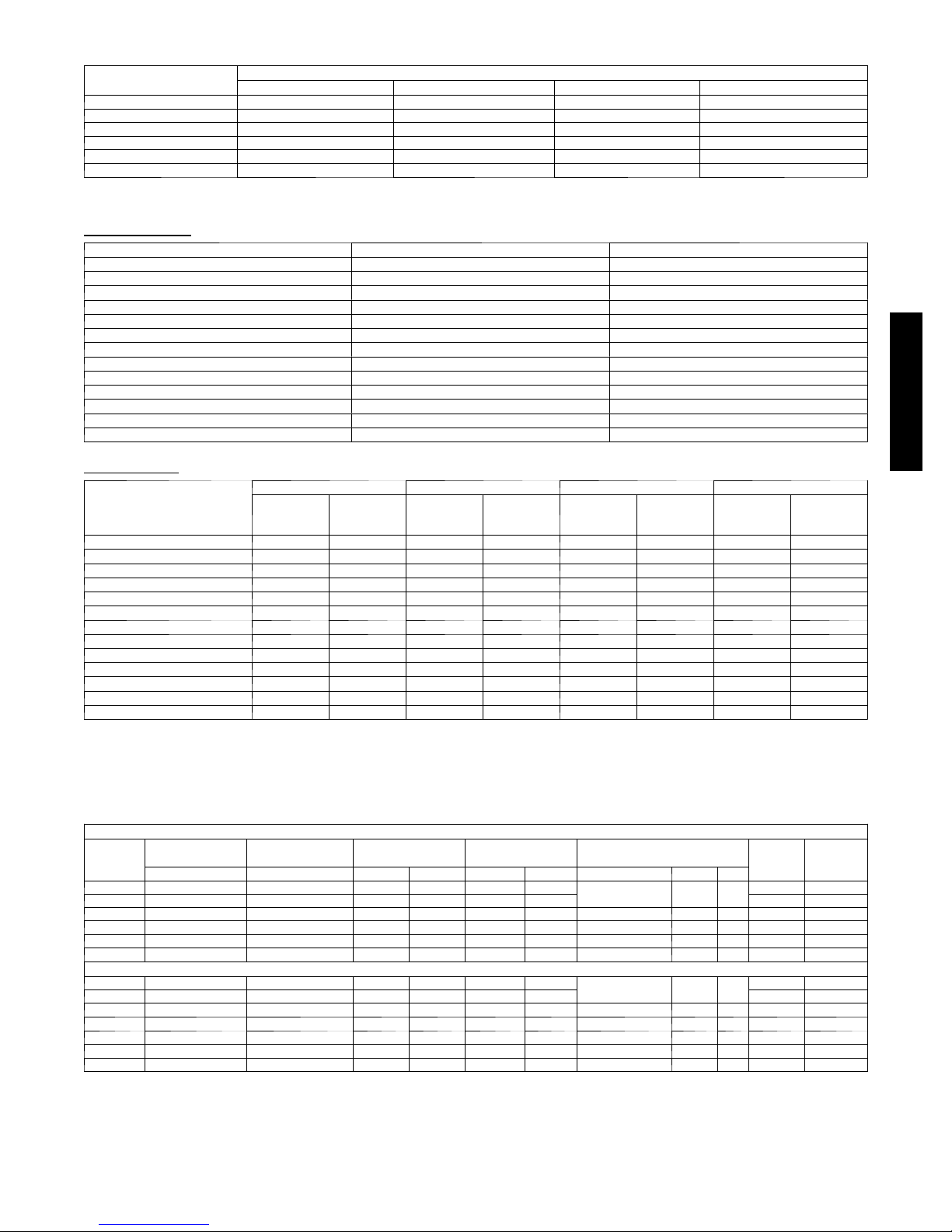
AIR THROW DATA
Unit Size
9K 18 (5.5) 21 (6.4) 23 (7.0) 28 (8.5)
12 K 20 (6.1) 23 (7.0) 25 (7.6) 30 (9.1)
18 K 22 (6.7) 27 (8.2) 33 (10.1) 39 (11.9)
24 K 25 (7.6) 29 (8.8) 34 (10.4) 42 (12.8)
30 K 35 (10.7) 37 (14.3) 40 (12.1) NA
36 K 37 (11.3) 40 (12.1) 45 (13.7) NA
Low Medium High Turbo
Approximate Air Throw ft. (m)
SOUND RATINGS
Outdoor Units
Model Number Sound Power dBA Sound Pressure dBA
3 8 GVC009 --- --- --- 1 63 53
3 8 GVC012 --- --- --- 1 65 55
3 8 GVC012 --- --- --- 3 62 52
3 8 GVC018 --- --- --- 3 66 56
3 8 GVC024 --- --- --- 3 63 53
3 8 GVC036 --- --- --- 3 75 65
3 8 GVQ0 0 9 --- --- --- 1 63 53
3 8 GVQ0 1 2 --- --- --- 1 65 55
3 8 GVQ0 1 2 --- --- --- 3 62 52
3 8 GVQ0 1 8 --- --- --- 3 66 56
3 8 GVQ0 2 4 --- --- --- 3 66 56
3 8 GVQ0 3 0 --- --- --- 3 72 62
3 8 GVQ0 3 6 --- --- --- 3 75 65
Indoor Units
Low Medium High Tur bo
Model Number
4 0 GVC009 --- --- --- 1 42 32 45 35 47 37 50 40
4 0 GVC012 --- --- --- 1 42 32 45 35 47 37 50 40
4 0 GVC012 --- --- --- 3 38 28 43 33 49 39 54 44
4 0 GVC018 --- --- --- 3 44 34 48 38 53 43 58 48
4 0 GVC024 --- --- --- 3 44 34 49 39 53 43 59 49
4 0 GVC036 --- --- --- 3 63 53 66 56 69 59 --- --4 0 GVQ0 0 9 --- --- --- 1 ( cool / h eat) 42/42 32/32 45/45 35/35 47/ 47 37/37 50/50 40/40
4 0 GVQ0 1 2 --- --- --- 1 ( cool / h eat) 42/42 32/32 45/45 35/35 47/ 47 37/37 50/50 40/40
4 0 GVQ0 1 2 --- --- --- 3 ( cool / h eat) 38/38 28/28 43/43 33/33 49/ 49 39/39 54/54 44/44
4 0 GVQ0 1 8 --- --- --- 3 ( cool / h eat) 44/44 34/34 48/48 38/38 53/ 53 43/43 58/58 48/48
4 0 GVQ0 2 4 --- --- --- 3 ( cool / h eat) 44/44 34/34 49/49 39/39 53/ 53 43/43 59/59 49/49
4 0 GVQ0 3 0 --- --- --- 3 ( cool / h eat) 58/58 48/48 64/64 54/54 67/ 67 57/57 --- --4 0 GVQ0 3 6 --- --- --- 3 ( cool / h eat) 63/63 53/53 66/66 56/56 69/ 69 59/59 --- ---
--- = N / A
NOTES:
1. Sound power ratings are per AHRI 270 and AHRI 350
2. Sound pressure ratings are estimated sound pressure, 3 feet (.91 m) from the unit, based on sound power data.
Sound
Power dB A
Sound
Pressure
dBA
Sound
Power dB A
Sound
Pressure
dBA
Sound
Power dB A
Sound
Pressure
dBA
Sound
Power dB A
Sound
Pressure
dBA
38/40GVC(Q)
ELECTRICAL DATA
Cooling Only
Unit
Size
9K 1 1 5 --- 1 --- 6 0 127/103 9.76 25.00 0.17 30
12 K 1 1 5 --- 1 --- 6 0 127/103 11.20 25.00 0.17 30 15 25
12 K 208/230 ---1 --- 60 253/187 7.30 16.50 0.25 21 208/230 0.19 15 10 15
18 K 208/230 ---1 --- 60 253/187 10.86 27.00 0.62 60 208/230 0.32 20 15 25
24 K 208/230 ---1 --- 60 253/187 11.71 41.00 0.62 60 208/230 0.45 35 16 25
36 K 208/230 ---1 --- 60 253/187 16.92 67.00 0.73 170 208/230 0.47 60 24 35
Heat Pump
9K 1 1 5 --- 1 --- 6 0 127/103 9.76 20.00 0.17 30
12 K 115 --- 1 --- 60 127/103 11.20 20.00 0.17 30 15 25
12 K 208/230 ---1 --- 60 253/187 7.30 16.50 0.25 21 208/230 0.19 15 10 15
18 K 208/230 ---1 --- 60 253/187 10.86 27.00 0.62 60 208/230 0.32 20 15 25
24 K 208/230 ---1 --- 60 253/187 11.71 41.00 0.62 60 208/230 0.45 35 16 25
30 K 208/230 ---1 --- 60 253/187 13.45 40.00 0.45 100 208/230 0.45 40 20 30
36 K 208/230 ---1 --- 60 253/187 17.50 67.00 0.73 170 208/230 0.47 60 24 40
* Permissible limits of the voltage range at which the unit wil l operate satisfactorily
{ Indoor fan powered from outdoor unit.
LEGEND
FLA --- F u l l L o a d A m p s
LRA --- L o c k e d R o t o r A m ps
MCA --- Minimum Circuit Amps
RLA --- RatedLoadAmps
System Voltage
V O L T --- P H --- H Z MAX / MIN RLA LRA FLA W VOLTS FLA W
Operating
Volt age*
Compressor Outdoor Fan Indoor Fan{
115 0.38 15
115 0.38 15
15
MCA
CB Amp
13 20
13 20
MAX
FUSE/
Page 16
PART1–GENERAL
1.01 System Description
A. Outdoor air-cooled split system compressor sections suitable
for on-the-ground, rooftop, wall hung or balcony mounting.
Units shall consist of a variable speed rotary compressor, an
air-cooled coil, propeller-type draw-through outdoor fan,
reversing valve, accumulator, metering devices, and control
box. Units shall discharge horizontally as shown on the
contract drawings. Units shall function as the outdoor
component of an air-to-air heat pump system.
B. Units shall be used in a refrigeration circuit matched to
duct-free heat pump fan coil units.
1.02 Agency Listings
C. Unit construction shall comply with ANSI/ASHRAE 15, latest
revision, and with NEC.
D. Units shall be evaluated in accordance with UL standard 1995.
E. Units shall be listed in CEC directory.
38/40GVC(Q)
F. Unit cabinet shall be capable of withstanding 500-hour salt
spray test per Federal Test Standard no. 141 (method 6061).
G. Air-cooled condenser coils shall be leak tested at 573 psig.
1.03 Delivery, Storage, And Handling
Units shall be shipped in one piece and shall be stored and handled
per manufacturer’s recommendations.
1.04 Warranty (For Inclusion By Specifying
Engineer)
PART 2 – PRODUCTS
2.01 Equipment
A. General:
Factory assembled, single piece, air-cooled outdoor unit. Contained
within the enclosure shall be all factory wiring, piping, controls,
and compressor.
B. Unit Cabinet:
1. Unit cabinet shall be constructed of galvanized steel,
bonderized and coated with baked-enamel finish on inside
and outside.
2. Unit access panel should be removable with minimal screws
and shall provide full access to the compressor, fan, and
control components.
3. Outdoor compartment shall be isolated and have an acoustic
lining to assure quiet operation.
C. Fans:
1. Outdoor fans shall be direct-drive propeller type, and shall
discharge air horizontally. Fan shall draw air through the
outdoor coil.
2. Outdoor fan motors shall be totally-enclosed, single phase
motors with class B insulation and permanently- lubricated
ball bearings. Motor shall be protected by internal thermal
overload protection.
3. Shaft shall have inherent corrosion resistance.
4. Outdoor fan openings shall be equipped with PVC
metal/mesh coated protection grille over fan.
GUIDE SPECIFICATIONS
HORIZONTAL DISCHARGE OUTDOOR UNITS
Size Range: 3/4 -- 3 Ton Nominal Cooling and Heating Capacity
Carrier Model Number: 38GVC(Q)
D. Compressor
1. Compressor shall be fully hermetic variable speed rotary
type.
2. Compressor shall be Three phase, inverter driven.
3. Compressor shall be equipped with oil system, operating oil
charge, and motor.
4. Motor shall be NEMA rated class F, suitable for operation
in refrigerant atmosphere.
5. Compressor assembly shall be installed on rubber vibration
isolators.
6. The inverter and compressor shall be protected against over
temperature and over current.
E. Outdoor Coil:
Coil shall be constructed of Aluminum fins mechanically bonded
to seamless copper tubes, which are cleaned, dehydrated and
sealed.
F. Refrigerant Components:
Refrigerant circuit components shall include brass external liquid
line service valve with service gauge port connections, suction line
service valve with service gage connection port, service gage port
connections on compressor suction and discharge lines with
Schrader type fittings with brass caps, accumulator, reversing valve
(on heat pump units).
G. Safeties:
Operating safeties shall be factory selected, assembled, and tested.
The minimum functions shall include the following:
1. Compressor discharge over temperature protection.
2. System low voltage protection.
3. Compressor overload protection.
4. Compressor over current protection.
5. IPM module protection.
H. Electrical Requirements:
1. Units shall operate on single-phase, 60Hz power at 115v for
unit sizes 009 - 012, and 60Hz power at 208/3230v for unit
sizes 012 -- 036.
2. Unit electrical power shall be a single point connection.
3. All power and control wiring must be installed per NEC
and all local electrical codes.
4. Units shall have high and low-voltage terminal block
connections.
16
Page 17

PART1–GENERAL
1.01 System Description
Indoor, wall-mounted, direct expansion fan coils are matched with
heat pump outdoor units.
1.02 Agency Listings
Unit shall be rated per ARI Standards 210/240 and listed in the
ARI directory as a matched system.
Units shall be evaluated in accordance with UL standard 1995.
Units shall be listed in CEC directory.
1.03 Delivery, Storage, And Handling
Units shall be shipped in one piece and shall be stored and handled
per manufacturer’s recommendations.
1.04 Warranty (For Inclusion By Specifying
Engineer)
PART 2 – PRODUCTS
2.01 Equipment
A. General:
Indoor, direct-expansion, wall-mounted fan coil. Unit shall be
complete with cooling/heating coil, fan, fan motor, piping
connectors, electrical controls, microprocessor control system, and
integral temperature sensing. Unit shall be furnished with integral
wall mounting bracket and mounting hardware.
B. Unit Cabinet:
Cabinet discharge and inlet grilles shall be attractively styled,
high-impact polystyrene. Cabinet shall be fully insulated for
improved thermal and acoustic performance.
C. Fans:
1. Fan shall be tangential direct-drive blower type with air
intake at the top of the unit and discharge at the bottom
front. Automatic, motor-driven vertical air sweep shall be
provided standard.
2. Air sweep operation shall be user selectable. The vertical
sweep may be adjusted (using the remote control) and the
horizontal air direction maybe be set manually.
D. Coil:
Coil shall be copper tube with aluminum fins and galvanized steel
tube sheets. Fins shall be bonded to the tubes by mechanical
expansion. A drip pan under the coil shall have a drain connection
for hose attachment to remove condensate. Condensate pan shall
have internal trap.
E. Motors:
Motors shall be totally enclosed, permanently lubricated ball
bearing with inherent overload protection. Fan motors shall be
3-speed.
F. C on tro ls:
Controls shall consist of a microprocessor-based control system
which shall control space temperature, determine optimum fan
speed, and run self diagnostics. The temperature control range shall
be from 62_Fto84_F (16.7_C to 28.9_C).
The unit shall have the following functions as a minimum:
1. Automatic restart after power failure at the same operating
conditions as at failure.
2. Temperature sensing control to enter set points and
operating conditions.
3. Wireless infrared remote control to enter set points and
operating conditions.
GUIDE SPECIFICATIONS
INDOOR WALL--MOUNTED DUCT--FREE UNITS
Size Range: 3/4 -- 3 Ton Nominal Cooling and Heating Capacity
Carrier Model Number: 40GVC(Q)
4. Automatic air sweep control to provide on or off activation
of air sweep louvers.
5. Dehumidification mode shall provide increased latent
removal capability by modulating system operation and set
point temperature.
6. Fan-only operation to provide room air circulation when no
cooling/heating is required.
7. Diagnostics shall provide continuous checks of unit
operation and warn of possible malfunctions. Error
messages shall be displayed at the unit.
8. Fan speed control shall be user-selectable: high, medium,
low or microprocessor controlled automatic operation
during all operating modes.
The unit shall be protected against the following:
1. Indoor coil freeze up
2. Indoor coil high temperature protection shall be provided to
detect excessive indoor discharge temperature when unit is
in heat pump mode.
3. Cold blow protection
G. Filters:
Units shall have filter track with factory-supplied cleanable filters.
H. Electrical Requirements:
Power is supplied from the indoor unit.
I. Operating Characteristics:
The 38/40GVC(Q) system shall have a minimum listed SEER
(seasonal energy efficiency ratio) of 16 SEER at ARI conditions,
and a minimum HSPF of 8.0.
J. Refrigerant Lines:
All units should have refrigerant line connections that can be
oriented to connect from the left, right, or back of unit. Both
refrigerant lines need to be insulated.
K. Special Features (Field Installed):
1. Condensate Pump: The condensate pump shall remove
condensate from the drain pan when gravity drainage
cannot be used. Pump shall be designed for quiet operation.
Pump shall consist of two parts: an internal reservoir/sensor
assembly, and a remote sound-shielded pump assembly. A
liquid level sensor in the reservoir shall stop cooling
operation if the liquid level in the reservoir is unacceptable.
38/40GVC(Q)
17
Page 18

38/40GVC(Q)
Copyright 2013 Carrier Corp. S 7310 W. Morris St. S Indianapolis, IN 46231
Manufacturer reserves the right to change, at any time, specifications and designs without notice and without obligations.
Edition Date:01/13
18
Catalog No. 38 ---40GVCQ--- 1PD
Replaces: New
 Loading...