

Page 1
38EN
HEATING A COOLING
Installation and Start-Up Instructions
SAFETY CONSIDERATIONS
Installing and servicing air conditioning equipment
can be hazardous due to system pressure and electrical
components. Only trained and qualified service personnel
should install or service air conditioning equipment.
Untrained personnel can perform basic maintenance,
such as cleaning and replacing filters. All other opera
tions should be performed by trained service personnel.
When working on air conditioning equipment, observe
precautions in literature and on tags and labels attached
to unit.
Follow all safety codes. Wear safety glasses and work
gloves. Use quenching cloth for brazing operations.
Have fire extinguisher available. Read these instruc
tions thoroughly. Consult local building codes and
National Electrical Code (NEC) for special installation
requirements.
A WARNING
Before installing or servicing system, always turn
off main power to system. There may be more
than one disconnect switch. Turn off accessory
heater power if applicable. Electrical shock can
cause personal injury.
Air-Cooled Condensing Units
#
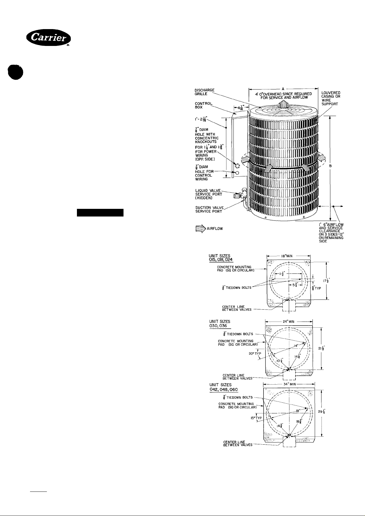
Step 1 — Check Equipment and Jobsite —
Install on a solid, level mounting pad. It is not recom
mended that unit be attached to pad using tiedown bolts.
Fasten unit to pad using holes provided in unit mounting
feet. See Fig. 1.
When installing, allow sufficient space for airflow
clearance, wiring, refrigerant piping and service. Main
tain a minimum of 4 ft clearance from obstructions above
and 18 in. on 3 sides of unit (12 in. on fourth side). Main
tain a distance of 24 in. between condensing units. Posi
tion so water or ice from roof or eaves cannot fall directly
on unit.
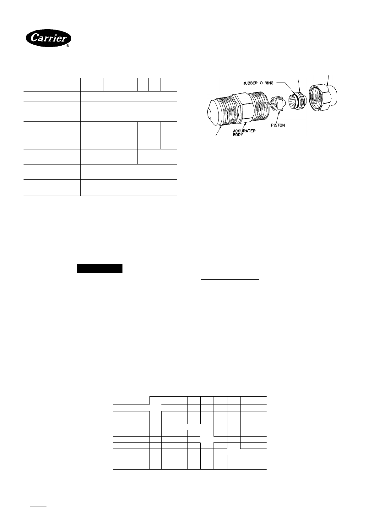
Step 2 — Replace Indoor AccuRater™ Piston, if required.
REPLACE ACCURATER REFRIGERANT CON
TROL PISTON in the indoor coil, if required, before
connecting refrigerant lines. Refer to Table 2 for proper
piston size.
Step 3 — Make Piping Connections — Outdoor
units may be connected to indoor sections using Carrier
accessory tubing package (refer to Service Data) or
field-supplied tubing of refrigerant grade, correct size
(see Table 1) and condition. For tubing requirements
beyond 50 ft, obtain information from your local
distributor.
Outdoor Units Connected to Carrier-Approved
Indoor Units — Outdoor units contain correct system
refrigerant charge for operation with indoor unit of the
same size when connected by 25 ft of field-supplied or
Carrier accessory tubing. Check refrigerant charge for
maximum efficiency (see Refrigerant Charging, page 4
and Service Data).
Certified dimension drawings avaiiabie upon request
Fig. 1 — Dimensions, Connections and
Mounting Pad (Refer to Table 1)
Manufacturer reserves the right to discontinue, or change at any time, specifications or designs without notice and without Incurring obligations.
Book И |4 PC101 Catalog No 563-825 PrintedinUSA Form38EN-3SI Pg 1 485 12-84 Replaces: 38EN-2SI
Tab |3a|2a
Pnr rAnlar^AmArtt Млтв iiea
Page 2
^ 38EN
HEATING A COOLING
Air-Cooled Condensing Units
Table 1 — Physical Data (Refer to Fig. 1)
MODEL 38EN
OPER WT (lb)*
REFRIGERANT
Control
COND FAN
Air Discharge
Air Qty (cfm)
Motor Rpm (60 Hz)
COND COIL (fins/in.)
Tube Diam
Rows
Face Area (sq ft)
Outer Row
Inner Row
DIMENSIONS (ft-in.)
Diameter A
Height B
CONN (in. ODF)
Suction
Liquid
REFRIG LINES (in. ODF)
Suction
Liquid
*Add 10 lbs for louvered casing (If so equipped) Weight Increases slightly
with addition of any accessories
t38EN048,060 require a I'/s-ln suction line for optimum performance. A
%- X 1'/8-in connection adapter accessory (Carrier Part No. 28AU900061)
is available If a %-in accessory tubing package is used, expect a 3%
capacity loss
015 018
94 111
024 030 036
142
111
AccuRater'“ (Installed In I.D. Coil)
Propelle
ir Type, Direct Drive
1950
1650
20
% in -
8 15
1- 5'/2
2- 1
Compatible F
%
Vertical
2800 1 4800
12 37
1-9’/2
tting (Suction and Liquid)
% 1 % 1 '/e 1 1’/at
042 048
146 182 200
22
1100
'/2
in , E-coil
1
17 11
2-7
%
%
%
060
228
16
2
17.11
2-5'/4
RETAINER
FLARE
CONNECTION
Fig. 2 — AccuRater (Bypass Type)
Components
CUT HERE-J
FLARE NUT
,0-RING
A CAUTION
DO NOT BURY MORE THAN 3 FT OF RE
FRIGERANT TUBING IN GROUND. If any
section of tubing is buried, there must be a 6-in.
vertical rise to the valve connections on the outdoor
unit. If more than the recommended length is buried,
refrigerant may migrate to cooler buried section
during extended periods of unit shutdown, causing
refrigerant slugging and possibly compressor damage
at start-up.
Table 2 — AccuRater™ Selection Chart
COND UNIT
38EN
(1- and 3-Ph)
015-0
018-0
024-0
030-0
030-2
036-0
042-0
048-0
060-0
060-1
Factory-installed piston Obtain replacement pistons
through local Carrier distributor
018 024
015
46
■
52 52 TXV — — — — —
— — 57
_
—
__
—
— —
— — — — 78
— —
Fig. 3 — Repair of Mechanicai Connection
CONNECT REFRIGERANT LINES to fittings on
outdoor unit suction and liquid service valves (Fig. 1).
Unit Compatible Fittings permit mechanical (quickconnect) or sweat connections.
Models 38EN048,060 — When using 1-1/8-in. fieldsupplied refrigerant suction line, sweat-connect suction
line to 1-1/8-in. end of required connection adapter.
Be sure to provide a heat sink at the service valve to
prevent damage during sweating operation. Connect
3/4-in. end of adapter to unit suction line Compatible
Fitting. Connect liquid refrigerant line to unit. When a
7/8-in. field-supplied suction line is used, provide a fieldsupplied 3/4-in. to 7/8-in. suction line adapter (not
necessary if 38LS accessory tubing is used).
ACCURATER'“ PISTON NO.
Evap Size (Coil or Fan Coil)
036 042 048 060
030
—
TXV
-
—
—
57
m
631
— —
— — —
TXV
— — — —
TXV
65
70 TXV — —
m
060
— — —
— — —
78 TXV
■
_
—
98
Manufacturer reserves the right to discontinue, or change at any time, specifications or designs without notice and without incurring obligations.
Bookll |4 PC101 Catalog No 563-825 PrIntedInUSA Form38EN-3SI Pg 2 12-84 Replaces: 38EN-2SI
Page 3

38EN
HEATING A COOLING
Mechanical Connection — Mate one set of connec
tions at a time.
1. Loosen nut on Compatible Fitting one turn. Do not
remove.
2. Remove plug and be sure O-ring is in the groove
inside the Compatible Fitting.
3. Cut tubing to correct length, deburr and size as
necessary.
4. Insert tube into Compatible Fitting until it bottoms.
Tighten nut until it bottoms on shoulder of fitting or
valve. Keep tube bottomed in Compatible Fitting
while tightening nut.
A CAUTION
If undersized, damaged or elliptically-shaped
tubing is used when making Compatible Fitting,
leaks may result.
Sweat Connection — Use refrigerant grade tubing.
1. Remove locking nut, rubber O-ring and Schrader core
and cap from valve service port.
2. Cut tubing to correct length, deburr and size as
necessary.
3. Insert tube in Compatible Fitting until it bottoms.
NOTE: Wrap top and bottom of service valves in wet
cloth to prevent damage by heat. Solder with lowtemperature (430 F) silver alloy solder.
4. Replace Schrader core and cap.
5. Evacuate or purge system using field-supplied
refrigerant.
Air-Cooled Condensing Units
Compatible Fitting Repair
MECHANICAL CONNECTION — Frontseat unit
service valves. Relieve refrigerant pressure froni tubing.
Back off locknut from Compatible Fitting onto tube. Cut
fitting between threads and O-ring. See Fig. 3. Remove
tubing section remaining in threaded portion of fitting.
Discard locknut.
Clean, flux and insert new tube end into remaining
portion of Compatible Fitting. Wrap valve in wet rag to
prevent damaging factory-made joints. Heat and apply
low-temperature (430 F) solder.
SWEAT CONNECTION — Frontseat unit service
valves. Relieve refrigerant pressure from tubing. Clean
and flux area around leak. Repair, using low-temperature
(430 F) solder.
Evacuate or purge evaporator coil and tubing system.
Add refrigerant charge. See Refrigerant Charging in
structions, page 4.
Step 4 — Make Electrical Connections — Be
sure field wiring complies with loeal and national fire,
safety and electrical codes, and voltage to system is
within limits shown in Table 3. Contact local power
company for correction of improper line voltage.
NOTE: Operation of unit on improper line voltage con
stitutes abuse and could affect Carrier warranty. See
Table 3. Do nOt install unit in system where voltage may
fluctuate above or below permissible limits.
See Table 3 for recommended fuse sizes. When making
electric connections, provide clearanee at unit for
refrigerant piping connections.
Table 3 — Electrical Data (60 Hz)
OUTDOOR
UNIT 38EN
015-3
018-3
024-3
030-3
036-3
042-3
048-3
060-3
030-5
036-5
042-5
048-5
060-5
036-6
042-6
048-6
060-6
FLA — Full Load Amps
HACR — Heating, Air Conditioning, Refrigeration
LRA — Locked Rotor Amps
MCA — Minimum Circuit Amps
RLA — Rated Load Amps
Manufacturer reserves the right to discontinue, or change at any time, specifications or designs without notice and without incurring obligations.
Bookh |4 PC101 Catalog No 563-825 PrintedinUSA Form38EN-3SI Pg3 485 12-84 Replaces: 38EN-2SI
V/PH
208-230/1
230/1
208-230/3Í
460/3Í
OPER VOLTS*
Max Min
254 197
254 197
254 187
508 414
COMPR FAN
LRA
36 0 6.9
53 0 10 1
65.0
88.0
97 0 21 0
118.0 24.2
110.0
150.0
70.0 103 2 1
78 0 128
90 0 15.4
105.0 18.3
136.0 20.6
39 0 6 1 1 1
45.0
35.0
49 0 10.4
RLA
130
187
25.0
35.3
83
8 8
'Permissible limits of the voltage range at which unit will operate
satisfactorily.
(Time-delay fuse
(3-Phase available only with base unit and SM option unit
NOTE: Control circuit is 24 v on all units and requires external
power source
FLA
1.6
1.6
1.6
2.1
2 1
2.5 32 7
2.5
2.5
2.1 18.1
2.5
2.5
2.5
1 3
1 3
1.3
MCA
100
14.0 20
17.9
24 6
28.4 45
33 8
46 7
14.9 25
21.7 35
25.4 40
28.2 45
87
11.7
12.3
14.3
MAX FUSEf OR
HACR TYPE
CKT BKR AMPS
15
30
35
50
50
60
30
15
20
20
20
Page 4

38EN
HEATING A COOLING
INSTALL BRANCH CIRCUIT DISCONNECT PER
NEC of adequate size to handle unit starting current.
Locate disconnect within sight from and readily acces
sible from unit, per Section 440-14 of National Electrical
Code (NEC).
ROUTE LINE POWER LEADS — Extend leads from
disconnect through power wiring hole provided (see
Fig. 1) and into unit splice area. Remove control box
cover to gain access to unit wiring.
CONNECT GROUND LEAD AND POWER WIRING
— Connect ground lead to ground connection in control
box for safety. Then connect power wiring. See Fig. 4.
Splice line power leads to yellow and black pigtails. Use
wire nuts and tape at each connection. Connect unit
wiring to copper power wiring only.
CONNECT CONTROL POWER WIRING — Route
24-v control wires through control wiring hole and
connect to pigtails supplied with unit (Fig. 1). Splice
control leads to brown and blue pigtails on all units.
See Fig. 5.
Use furnace or fan coil transformer as 24-v (40-va
minimum) supply for system as shown in Fig. 5, or use
accessory transformer (refer to Service Data).
NOTE: Some 38EN units are equipped with a fan time
delay. This permits indoor fan to continue to operate for
90 seconds, which provides additional cooling after
compressor has eyeled off. Refer to separate installation
instructions packaged with fan time delay (shipped
with unit).
A WARNING
Air-Cooled Condensing Units
Refrigerant Charging (Refer to Fig. 6 and Table 5)
A CAUTION
To prevent personal injury, wear safety glasses
and gloves when handling refrigerant. Do not
overcharge system. This can cause compressor
flooding.
I-PHASE
-GROUND LEAD
CONN. TO
DISCONNECT
PER NEC
r__________________
3-PHASE
CONN. TO
DISCONNECT
PER NEC
--GROUND LEAD --J-SGROUNDING LUG
-C®1grounding lug
- — BLK
----------------
YEL-
1- PHASE
COND UNIT
BLK -
BLU-
• YEL -
To avoid personal injury, be sure indoor
blower has stopped before attempting service
or maintenance.
Step 5 — Start-Up
1. Energize crankease heater a minimum of 24 hours
before starting unit. To energize heater only, set
thermostat at OFF position and close electrical dis
connect to outdoor unit.
2. Backseat (open) liquid and suction line serviee valves.
3. Set thermostat selector switch at OFF.
4. Set room thermostat at desired temperature. Be sure
set point is below indoor ambient temperature.
5. Close electrieal diseonnects to energize system.
6. Set room thermostat at COOL and fan switch at FAN
or AUTO, as desired. Operate unit for 15 minutes.
Check system refrigerant charge. See Refrigerant
Charging, below.
Motors and controls are designed to operate satisfaetorily in the voltage range shown in Table 3. If
necessary to use manifold gages for servicing, refer to
Carrier Standard Service Techniques Manual, Chapter 1,
Refrigerants, page 1 - 5, Fig. 8, for bypass method of
returning charge to system. Removal of liquid line
eharging hose without following these precautions could
result in some loss of charge.
—fr-i— SPLICE CONNECTIONS
--------------
--------------
FIELD WIRING
FACTORY WIRING
3-PHASE COND UNIT
Fig. 4 — Line Power Connections
Table 4 — Service Data
MODEL
38EN
015300
015310 AK8515E
018300
018310
024300, H21B243ABCA
030300
030320
036300, H21A373ABCA
042300
048300 PC5316BD 76
060300,
030500
036500 H21A373DBD
042500 H21A463DBD 50
048500 PY5316AD
060500, PY6716AF
036600
042600
048600
060600,
'Factory refrigerant charge is adequate when indoor unit and outdoor unit
are the same size and are connected with 25 ft or iess of fieid-suppiied
tubing of recommended size or Carrier accessory tubing
COMPRESSOR
REK3-0125-PFV
H21B193ABCA
RES3-0175
310
H21A313ABCA
MD3215GG
320
H21A463ABCA 50 47
PC6716AG 76
PC6716AG
310
H21A313DBD 40
PY6716AF 76
510
H21A373DBE
H21A463DBE
PH5316AD
PH6716AF
610
PH6716AF
OIL
CHARGE (oz)
Recharge
Initial
24
17
40 37
24 20
40
40
46
50
76
50 47
76
76
50
50
76
76
76 62
R-22
CHG* (lb)
20
15 3 20
37
37
44
47
62
62
62
37
47 7 20
62
62
62
47
47
62
62
3 60
3 60 1650
3 70
3 80
5 60
6 70
5 80
7 20
7 60
9 60
12.50
5 60
5 80
7 60
9 60
12.50
5 80
7 20
7 60
9 60
12 50
OUTDOOR
FAN RPM
1100
Manufacturer reserves the right to discontinue, or change at any time, specifications or designs without notice and without incurring obligations.
Book|1 |4 PC 101 Catalog No. 563-825 PrintedinUSA Form38EN-3SI Pg4 485 12-84 Replaces: 38EN-2SI
Page 5

38EN
HEATING A COOLING
THERMOSTAT SUBBASE
THERMOSTAT SUBBASE
ARRANGEMENT B-ONE TRANSFORMER
(COOLING AND ONE-STAGE HEATING)
THERMOSTAT SUBBASE
99TZ90036I20
Air-Cooled Condensing Units
Table 5 — 38EN Chargemaster® Charging
OUTDOOR
TEMP
Chart (AccuRater™ System)
EVAPORATOR TEMPERATURE (F)
(F)
60 32 40 51
62 30 38 39
64 28 37 47 60
66
68
70
72 31 39 50
74
76
78
80
82
86
88
90
92
94
96
98
100
102
104 39 46
106 45 51
108 43
110 41
112
114
21 I 25 I 28 I 31 I 34 I 37 I 4045 | 48
Suction Line Temperature ^)
27
35 45 57
34 43 54
32 41 52
67
64
61 72
30 37 48 58 69
29 36
27 35
26 33 42
46 56
66
44 54 63
52
61
75ii
72::
32 40 50 59 68
35
34
33
46
55 63 73
44
53 61
42 51
41
49 57
39 47
38
45 53 61
44
36
42
41
59 68
55 63 72
51 59
49 57
48 55
29 37
Example
70 81
65 75
53 61
49 57
47
46
85
78 90
86
83
70 80
67 77
65 75
63
73
70
59 68
65
55 63
53 61
50
59
(COOLING AND TWO-STAGE HEATING)
*IFR and IFM are located In furnace on heating-cooling applica
tions If accessory IFR is required for cooling-only applications,
locate (IFR) in fan coil
C — Contactor (12-va)
HC — Heating Control
IFM — Indoor Fan Motor
IFR — Indoor Fan Relay
Trans — Transformer
NOTE Refer to unit wiring label for wire colors: C to G andCto Y
connections
________
________
Fig. 5 — Control Circuit Connections
Manufacturer reserves the right to discontinue, or change at any time, specifications or designs without notice and without incurring obligations.
Book II 14 PC 101 Catalog No 563-825 Printed inUS A Form38EN-3SI Pg 5 12-84 Replaces: 38EN-2SI
Tah li^alPa
Field Splice
Field Wiring
Factory Wiring
Fig. 6 — 38EN Charging Chart
(AccuRater™ System)
For renlacement IteniA iiao ('.ntrlar Parte
Page 6

38EN
HEATING A COOLING
Air-Cooled Condensing Units
Manufacturer reserves the right to discontinue, or change at any time, specifications or designs without notice and without incurring obiigations.
Bookll 14 PC 101 Catalog No 563-825 PrintedinUSA Form 38EN-3SI Pg6 485 12-84 Replaces; 38EN-2SI
For reolacement items use Carrier Soecified Parts
 Loading...