

Page 1
38EH
HEATING & COOLING
Installation and Start-Up Instructions
SAFETY CONSIDERATIONS
Installing and servicing air conditioning equipment
can be hazardous due to system pressure and electrical
components. Only trained and qualified service personnel
should install or service air conditioning equipment.
Untrained personnel can perform basic maintenance,
such as cleaning and replacing filters. All other opera
tions should be performed by trained service personnel.
When working on air conditioning equipment, observe
precautions in literature and on tags and labels attached
to unit.
Follow all safety codes. Wear safety glasses and work
gloves. Use quenching cloth for brazing operations. Have
fire extinguisher available. Read these instructions
thoroughly. Consult local building codes and NEC
(National Electrical Code) for special installation
requirements.
A WARNING
Before installing or servicing system, always turn
off main power to system. There may be more than
one disconnect switch. Turn off accessory heater
power if applicable. Electrical shock can cause
personal injury
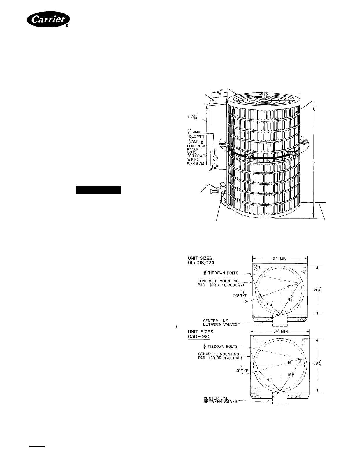
Step 1 — Install on a Solid, Level Mounting
Pad — It is recommended that unit be attached to pad
using tiedown bolts. Fasten unit to pad using holes pro
vided in unit base. See Fig. I
When installing, allow sufficient space for airflow
clearance, wiring, refrigerant piping and service. Main
tain a minimum of 4 ft clearance from obstructions above
and 18 in around unit (I2in. on valve side). Main
tain a distance of 24 in. between condensing units.
Position so water or ice from roof or eaves cannot
fall directly on unit.
Air-Cooled Condensing Units
4'0" OVERHEAD SPACE REQUIRED
CONTROL
BOX
I DIAM
HOLE FOR^
CONTROL
WIRING
LIQUID
VALVE '
SERVICE
PORT
(HIDDEN)
SUCTION VALVE
SERVICE PORT
' AIRFLOW
FOR SERVICE AND AIRFLOW
I-6 AIRFLOW AND SERVICE
CLEARANCE AROUND UNIT
-I2" ON VALVE SIDE
LOUVERED
CASING
Step 2 — Replace Indoor AccuRater™ Piston
if Required — Check indoor coil piston to see if it
matches the required piston listed in Table 2. If it does
not match, replace indoor coil piston with piston shipped
with this outdoor unit (located in plastic bag taped to
valves). See Fig. 2.
Step 3 — Make Piping Connections — Outdoor
units may be connected to indoor sections using Carrier
accessory tubing package or field-supplied tubing of
refrigerant grade, correct size (see Table I) and condition.
For tubing requirements beyond 50 ft, obtain informa
tion from Carrier distributor.
OUTDOOR UNITS CONNECTED TO CARRIERAPPROVED INDOOR UNITS — Outdoor units con
tain correct system refrigerant charge for operation with
indoor unit of the same size when connected by 25 ft of
field-supplied or Carrier accessory tubing. Check refrig
erant charge for maximum efficiency (see Refrigerant
Charging)
Bookh |4 PC101 Catalog No 533-813 PrintedinUSA Form38EH-5SI Pg 1 1-86 Replaces: 38EH-3SI
Tab J3a 2a
Manufacturer reserves the right to discontinue, or change at any time, specifications or designs without notice and without incurring obligations.
For replacement items use Carrier Specified Parts
Certified dimension drawings available upon request
Fig. 1 — Dimensions, Connections and
Mounting Pad (Refer to Table 1)
Page 2
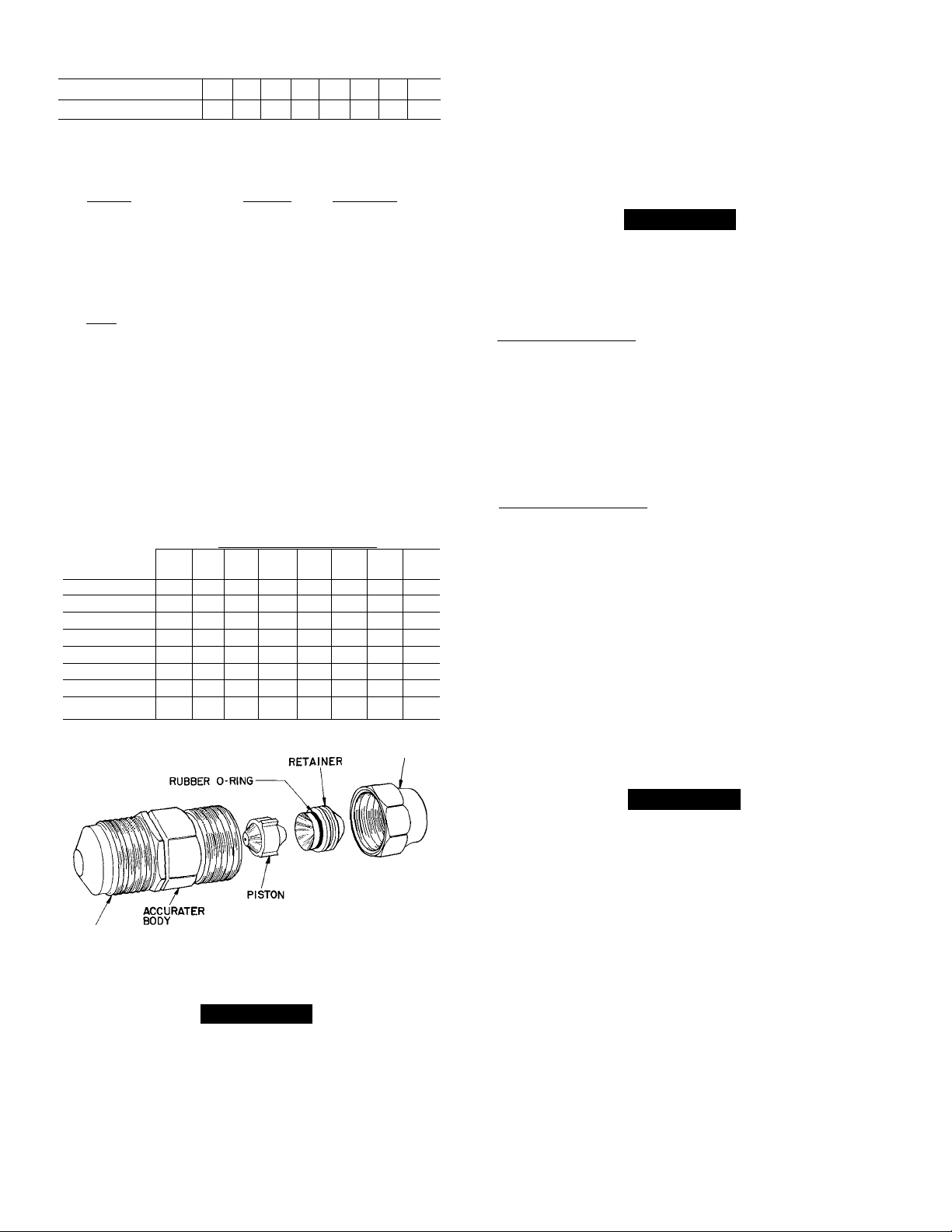
Table 1
MODEL 38EH
OPER WT (lb)* 116 131
REFRIGERANT
Control
CONDFAN
Air Discharge
Air Qty (dm)
Motor Rpm (60 Hz)
Motor Hp
_________
CONOCOIL(fins/in.)
Tube Diam
Rows
Face Area (sq ft)
DIMENSIONS (ft-ln.)
Diameter A
Height
___________
CONN (in. ODF)
Suction
Liquid
________
REFRIG LINES (In. ODF)
Suction
Liquid
'Weight increases slightly with addition of any accessories
t38EH048,060 require a I'/a-ln suction line for optimum performance. A
%- X I'/a-in connection adapter accessory (Carrier Part No. 28AU900061)
is available If a %-in accessory tubing package is used, expect a 3%
capacity loss
Physical Data (Refer to Fig. 1)
015 018
B
Compatible Fitting (Suction and Liquid)
024
030 036 042
148
171 177
AccuRater™ (Installed in i.D. Coil)
Propeller Type, Direct Drive, 1-Speed
1850 3100 1 4000
830 I 850
V.0 I
12.37 17.11
1-9%
Vertical
________
'k in , E-coil
1 I 2
22
'/a I '/; I %
16
2-7
178
2-5'/4
% I 14
Table 2 — AccuRater™ Chart
ACCURATER PISTON NO.
COND UNIT
38EH
(1- and 3-Ph)
015 46 46
018
024
030
036
042
048
060
014/
015
—
— — —
— — — —
—
—
— — — —
Indoor Coil Size (28—)
and Indoor Fan Coil Size (40—)
024
018
49
—
TXV
49
61
030
—
TXV
61
70
036 042
— —
—
TXV
70
76 76
_
__
— —
—
— —
—
—
—
—
TXV
82
—
—
048
— —
—
— —
TXV
82 TXV
80 80
—
FLARE NUT
048 060
210
236
I'/at
060/
062
—
—
98
CONNECT REFRIGERANT LINES to fittings on out
door unit suction and liquid service valves (Fig. 1). Unit
Compatible Fittings permit mechanical (quick-connect)
or sweat connections.
Compatible Fitting on outdoor section has aluminum
plugs located beneath compatible nut — one plug each
on suction and liquid valves. Plugs keep contaminants
out of Compatible Fitting.
A CAUTION
When removing compatible nut, be careful pressure
build-up does not cause aluminum plug(s) to blow
and cause personal injury. After tubing is hooked up,
discard plug(s).
Models 38EH048,060 — When using 1-1/8 in. fieldsupplied refrigerant suction line, sweat-connect suction
line to 1-1/8 in. end of required connection adapter. Be
sure to provide a heat sink at the service valve to prevent
damage during sweating operation. Connect 3/ 4-in. end of
adapter to unit suction line Compatible Fitting. Connect
liquid refrigerant line to unit. When a 7/8-in. field-
supplied suction line is used, provide a field-supplied
3/4-in. to 7/8-in. suction line adapter (not necessary if
38LS accessory tubing is used).
Mechanical Connection— Mate one set of connections
at a time.
1. Remove nut on Compatible Fitting.
2. Remove plug and be sure O-ring is in the groove
inside the Compatible Fitting.
3. Cut tubing to correct length, deburr and size as neces
sary. Slide nut onto tube
4. Insert tube into Compatible Fitting until it bottoms.
Tighten nut until it bottoms on shoulder of fitting
or valve. Keep tube bottomed in Compatible Fitting
while tightening nut.
NOTE: If using Carrier accessory tubing package,
make connections within 2 minutes to avoid refrig
erant loss.
5. If using field-supplied tubing evacuate or purge system
using field-supplied refrigerant.
FLARE
CONNECTION
Fig. 2 — AccuRater™ (Bypass Type) Components
A CAUTION
DO NOT BURY MORE THAN 3 FT OF REFRIG
ERANT TUBING IN GROUND. If any section of
tubing is buried, there must be a 6-in. vertical rise
to the valve connections on the outdoor unit. If more
than the recommended length is buried, refrigerant
may migrate to cooler buried section during extended
periods of unit shutdown, causing refrigerant slug
ging and possibly compressor damage at start-up.
A CAUTION
If undersized, damaged or elliptically-shaped tubing
is used when making Compatible Fitting, leaks may
result.
Sweat Connection— Use refrigerant grade tubing.
Remove locking nut, plug, rubber O-ring and Schrader
1.
core and cap from valve service port.
Cut tubing to correct length, deburr and size as
2.
necessary.
Insert tube in Compatible Fitting until it bottoms.
3.
NOTE: Wrap top and bottom of service valves in wet
cloth to prevent damage by heat. Solder with lowtemperature (430 F) silver alloy solder.
Replace Schrader core and cap.
4.
Evacuate or purge system using field-supplied
5.
refrigerant.
Page 3

CUT HERE
Fig. 3 — Repair of Mechanical Connection
Compatible Fitting Repair
MECHANICAL CONNECTION — Frontseat unit
service valves. Relieve refrigerant pressure from tubing.
Back off locknut from Compatible Fitting onto tube.
Cut fitting between threads and 0-ring. See Fig. 3.
Remove tubing section remaining in threaded portion
of fitting. Discard locknut.
Clean, flux and insert new tube end into remaining
portion of Compatible Fitting. Wrap valve in wet rag to
prevent damaging factory-made joints. Heat and apply
low-temperature (430 F) solder.
SWEAT CONNECTION — Frontseat unit service
valves. Relieve refrigerant pressure from tubing. Clean
and flux area around leak. Repair, using low-temperature
(430 F) solder
Evacuate or purge evaporator coil and tubing system.
Add refrigerant charge. See Refrigerant Charging.
Step 4 — Make Electrical Connections — Be
sure field wiring complies with local and national fire,
safety and electrical codes, and voltage to system is
within limits shown in Table 3. Contact local power
company for correction of improper line voltage.
NOTE; Operation of unit on improper line voltage
constitutes abuse and could affect Carrier warranty. See
Table 3. Do not install unit in system where voltage may
fluctuate above or below permissible limits.
See Table 3 for recommended fuse sizes. When making
electric connections, provide clearance at unit for refrig
erant piping connections.
INSTALL BRANCH CIRCUIT DISCONNECT PER
NEC of adequate size to handle unit starting current.
Locate disconnect within sight from and readily acces
sible from unit, per Section 440-14 of NEC (National
Electrical Code^
ROUTE LINE POWER LEADS — Extend leads from
disconnect through power wiring hole provided (see
Fig. 1) and into unit splice area. Remove control box
cover to gain access to unit wiring.
CONNECT GROUND LEAD AND POWER WIRING
— Connect ground lead to ground connection in control
box for safety. Then connect power wiring. See Fig. 4.
Splice line power leads to yellow and black pigtails. Use
wire nuts and tape at each connection. Connect unit
wiring to copper power wiring only.
I-PHASE
CONN. TO
DISCONNECT
PER NEC
--------
____________________
Q SPLICE CONNECTIONS
--------------FIELD WIRING
-------------
FACTORY WIRING
GROUND LEAD -
-^GROUNDING LUG
- — BLK
.4=^
------------------
YEL--------
I- PHASE
COND UNIT
Fig. 4 — Line Power Connections
CONNECT CONTROL POWER WIRING — Route
24-v control wires through control wiring hole and
connect to pigtails supplied with unit (Fig. 1). Splice
control leads to brown and blue pigtails on all units.
See Fig. 5.
Use furnace or fan coil transformer as 24-v (40-va
minimum) supply for system as shown in Fig. 5, or use
accessory transformer.
NOTE: Some 38EH units are equipped with a fan time
delay. This permits indoor fan to continue to operate for
OUTDOOR
UNIT 38EH
015
018
024
030
036
042
048
060
036-5
042-5
048-5
060-5
036-6
042-6
048-6
060-6
FLA — Full Load Amps
HACR — Heating, Air Conditioning, Refrigeration
LRA — Locked Rotor Amps
MCA — Minimum Circuit Amps
RLA — Rated Load Amps
V/PH
208-230/1
230/1
208-230/3
460/3
Table 3 Electrical Data (60 Hz)
OPER VOLTS*
Max
253
253
253
508 414
Min
197
207
187
COMPR
LRA RLA CKT BKR (Amps)
37 5
43 0
66 0
88 0 18 6 09
88 0 18 1 0.9
108 0
110.0
130 0 29 3 1 9
65.1
74.0 17.1
92 0
98 0
32 8 4 76
37 0
46 0
49.0
FAN
FLA
64 07
78 0.7
140 07
21 4 0.9
26 0 25
97
19 6
20 9
69
72
104
‘Permissibie iimits of the voltage range at which unit wiii operate
satisfactoriiy
fTime-delay fuse
NOTE; Controi circuit is 24 v on ali units and requires externai
power source
09
09
2 5
1.9
1 6 74
1 6
1 6
1 6
MCA
87
105
18 2
24 2
23 6
27.7
35.0
38.5
15.3
22.3
27 0
28.0
103
106
145
MAX FUSEt OR
HACR TYPE
15
15
30
40
40
45
50
60
25
35
45
45
15
15
15
20
886
Page 4

THERMOSTAT SUBBASE
99TZ90008I25 OR
99TZ9000II50
ARRANGEMENT A-(COOLING ONLY)
THERMOSTAT SUBBASE
ARRANGEMENT B-ONE TRANSFORMER
(COOLING AND ONE-STAGE HEATING)
THERMOSTAT SUBBASE
99TZ90036I20
TO IFM LINE
VOLTAGE
IFM)-|POWER
SUPPLY
___
90 seconds, which provides additional cooling after
compressor has cycled off. Refer to separate installation
38EH
instructions packaged with fan time delay (shipped with
unit).
^
A WARNING
To avoid personal injury, be sure indoor blower has
stopped before attempting service or maintenance.
Step 5 — Start-Up
When equipped with a crankcase heater, energize
TRANS
1.
heater a minimum of 24 hours before starting unit. To
energize heater only, set thermostat at OFF position
and close electrical disconnect to outdoor unit.
Backseat (open) liquid and suction line service valves.
2.
Unit is shipped with valve stem(s) frontseated, and
3.
caps installed. Replace stem caps after system is opened
to refrigerant flow (backseated). Replace caps finger
tight and tighten additional 1/6 turn with wrench
See sticker on valve cap.
4. Set thermostat selector switch at OFF.
5. Set room thermostat at desired temperature. Be sure
set point is below indoor ambient temperature
6. Close electrical disconnects to energize system
7. Set room thermostat at COOL and fan switch at FAN
or AUTO, as desired. Operate unit for 15 minutes.
Check system refrigerant charge. See Refrigerant
Charging, below.
Motors and controls are designed to operate satis
factorily in the voltage range shown in Table 3. If neces
sary to use manifold gages for servicing, refer to Carrier
Standard Service Techniques Manual, Chapter 1, Refrig
erants, page 1-5, Fig. 8, for bypass method of returning
charge to system. Removal of liquid line charging hose
without following these precautions could result in some
loss of charge.
ARRANGEMENT C-ONE TRANSFORMER
(COOLING AND TWO-STAGE HEATING)
*IFR and IFM are located in furnace on heating-cooling applica
tions If accessory IFR is required for cooling-only applications,
locate (IFR) in fan coil
— Contactor (12-va)
c
— Heating Control
HC
— Indoor Fan Motor
IFM
— Indoor Fan Relay
IFR
— Transformer
Trans
NOTE' Refer to unit wiring label for wire colors C to G and Cto Y
connections.
^ Field Splice
_ Field Wiring
Factory Wiring
Fig. 5 — Control Circuit Connections
Refrigerant Charging (Refer to Tables 4 and 5)
A CAUTION
To prevent personal injury, wear safety glasses and
gloves when handling refrigerant. Do not overcharge
system. This can cause compressor flooding.
1. Operate unit a minimum of 10 minutes before check
ing charge.
2. Measure suction pressure by attaching a gage to
suction valve service port.
3. Measure suction line temperature by attaching a
service thermometer to unit suction line near suc
tion valve. Insulate thermometer for accurate
readings.
4. Measure outdoor coil inlet air dry-bulb temperature
with a second thermometer.
5. Measure indoor coil inlet air wet-bulb temperature
with a sling psychrometer.
6. Refer to Table 4. Find air temperature entering out
door coil and wet-bulb temperature entering indoor
coil. At this intersection note the superheat.
7. Refer to Table 5. Find superheat temperature and
suction pressure, note suction line temperature.
Page 5

If unit has higher suction line temperature than
charted temperature, add refrigerant until charted
temperature is reached.
If unit has lower suction line temperature than
charted temperature, bleed refrigerant until charted
temperature is reached.
Table 4 — Superheat Charging Table
(Superheat Entering Suction Service Valve)
10. If air temperature entering outdoor coil or pressure
at suction valve changes, charge to new suction line
temperature indicated on chart.
11. This procedure is valid, independent of indoor air
quantity.
NOTE: For service data, refer to separate service manual
for Models 38EH,EN,ES,QH,QN,QS.
OUTDOOR
TEMP (F)
55
60
65
70
75
80
85
90
95
100
105
110
115
Do not attempt to charge system under these conditions or refrigerant slugging
may occur
50 52
INDOOR COIL ENTERING AIR TEMP (F WB)
54 56 58 60
62 64
66
12 14 17 20 23 26 29 32
12
10
15 18 21 24 27 30 33 35
10
13 •16 19
21
24
27
10 13 16 19 21 24 27 30
12 15
12
21 24 28
18
15 18
11 15 19
13 16 20
10
68 70
35 37
30 33
21 25
14
12
Tables — Required Suction-Tube Temperature (F)
(Entering Suction Service Valve)
TEMP (F)
0
2
4
6
8
10
12
14
16
18
20
22
24
26
28
30
32
34
36
38
40
61.5 64.2
35 37
37
39 41
41 43
43 45
45 47 49
47
49 51
51 53
53 55
55 57 59
57 59 61
59
61 63 65
63 65
65 67 69
67
69 71
71 73
73 75
75 77 79
67.1 70.0
39 41
41 43
39
43 45
45 47
47 49
51 53 55 57
49
53 55 57 59 61
55
57 59
63
61
67
69
71 73 75 77 79
73 75
75 77
77 79
73.0 76.0
43
45
47 49 51
49
51 53 55
51
53 55 57
57
59 61 63
61
61
63 65 67
63
65
67 69 71
67
69 71 73
69 71 73 75
71
77 79 81
81
83 85 87
79.2 82.4 85.7
45 47
47
51
63
67
65
73 75 77
79 81 83
81 83 85
74 76
72
40 42 45
40 43
38
38 41
36
33 36 39
31 34 37
28 31 35
22 26 30 33
27
24
18 22 25 29
15
20 23
13 17 22
15 20 25
11
14 18 23
49 51
49
51 53
53 55
53
55 57
57 59
59 61
59
61 63
63 65
65
65
67 69
69 71
69
71 73
73 75
75 77
77 79
79
81 83
83 85
85 87
87
89 91
31
27
26
67
81
89
Page 6

Manufacturer reserves the right to discontinue, or change at any time, specifications or designs without notice and without incurring obligations.
Book|l 14 PC101 Catalog No 533-813 PrintedinUSA Form38EH-5SI Pg6 886 1-86 Replaces: 38EH-3SI
Tab l3a|2a
For replacement items use Carrier Specified Parts.
 Loading...