

Page 1
38E,Q
HEATING & COOLING
Condensing Units and Heat Pumps
Service Manual
38EH,EN,ES,QH,QN,QS
TABLE OF CONTENTS
Page
INTRODUCTION
Models and SEER Ranges...................................... 1
Factory-Installed Options
SAFETY CONSIDERATIONS
SERVICE.................................................................... 3
Cabinet...................................................................... 3
• REMOVING LOUVERED CASING
• REMOVING FAN ORIFICE
• ELECTRICAL BOX ACCESS
Electrical
.................................................................
• CONTACTORS
• CAPACITORS
• TIME GUARD II
• CRANKCASE HEATER
• PRESSURE SWITCHES
• DEFROST THERMOSTATS ,
• PRINTED-CIRCUIT CONTROL BOARD
• FAN MOTORS
• SERVICE SENTRY CONTROL BOARD
• OUTDOOR THERMOSTATS
......................................................
.......................................
.......
............................
1,2
2
3
5-11
Compressor
......................... ..................................
• MECHANICAL FAILURES
• ELECTRICAL FAILURES
• SYSTEM CLEAN-UP AFTER BURN-OUT
• COMPRESSOR REMOVAL AND
REPLACEMENT
Refrigeration System
..........................................
15-20
• REFRIGERATION CYCLE
• LEAK DETECTING
• SERVICE VALVES
• CARRIER COMPATIBLE FITTING
• ACCURATER™ (Bypass type) COMPONENTS
• REVERSING VALVE
• COIL REMOVAL
• COIL CLEANING
• LIQUID LINE STRAINER
• ACCUMULATOR
• SYSTEM CHARGING (for all approved
combinations)
Page
12-15
INTRODUCTION
This Service Manual enables a service technician to
.service and repair a family of similar condensing units
and heat pumps. Outwardly, many models appear
Models and SEER Ranges
Table 1 — Condensing Units
MODEL
38EH015 22
38EH018 22
38EH024 22
38EH030 30
38EH036 30 9.0
38EH042 30 9,0
38EH048 30 9.0
38EH060
38EN015
38EN018
38EN024
38EN030 22
38EN036
38EN042 30 8.0
38EN048 30 8.0
38EN060
38ES018 30
38ES024
38ES030 30
38ES036
38ES042 30
38ES048 30
38ES060 39
’SEER — Seasonal Energy Efficiency Ratio. The higher the number, the
less electrical power required to reach a given capacity. SEER
is derived by dividing output energy by input energy.
DIAMETERS SEER*
(in.)
30
17
17
17
22
30 8.0
30 10.0
30
(Nominal)
9.0
9.0
9.0
9.0
9.0
8.0
8.0
8.0
8.0
8.0
10.0
10.0
10.0
10.0
10.0
10.0
similar, however, there are distinct differences. Tables 1
and 2 help to differentiate these differences.
Table 2 — Heat Pumps
MODEL
38QH015
38QH018
38QH024 30
38QH030 30
38QH036
38QH042 30
38QH048
38QH060 39
38QN015
38QN018
38QN024 22
38QN030
38QN036 30
38QN042 30
38QN048 30
38QN060 30
38QS018 30
38QS024
38QS030 30
38QS036 30
38QS042 30
38QS048
38QS060 39
tC.O.P. — Coefficient of Performance (heating), determined by dividing
DIAMETERS
(in.)
22
22
30
30
17
17
22
30
30
Btu output by power input required to producethis Btu output.
SEER*
(Nominal)
■ 9.0
9.0
9.0
9.0 2.85
9.0
9.0
9.0
9.0 2.85
8.0
8.0
8.0
8.0 2.55
8.0
8.0
8.0
8.0
10.0
10.0
10.0
10.0
10.0 2.85
10.0
10.0 2.85
CiO.P.t
(Minimum)
2.85
2.85
2.85
2.85
2.85
2.85
2.55
2.55
2.55
2.55
2.55
2.55
2.55
2.85
2.85
2.85
2.85
2.85
Manufacturer reserves the right to discontinue, or change at any time, specifications or designs without notice and without incurring obligations.
Book |l 1 |4 |4
Tab jsa
5a|2a|5a
PC 101
Catalog No. 563-857 Printed in U.S.A. Form 38E.Q-1SM
For replacement items use Carrier Specified Parts.
Pgi
11-85
Replaces; New
Page 2
Factory-Installed Options — Any condensing unit
or heat pump listed in Tables 1 and 2 may be ordered as
Basic or in one of 3 factory-option packages. Package
designations are included in model number (excluding
Table 3 — Option Packages
Basic). Example: 38EN0243015A/. SM designates this
unit as sheet metal option package. Option package
designations are shown in Table 3.
Basic
Sheet Metal Option (SM)
Deluxe Option (DL)
Custom Deluxe Option (CD) Same unit as (DL) except for addition of
Basic
Sheet Metal Option (SM)
38EH,ES
Standard unit with no added options.
Same unit as Basic except with addition
of louvered inlet casing.
Same unit as (SM) except for addition ■
of start assist components on single
phase units, crankcase heater, highand low-pressure switches, and
accumulator.
sound shield around compressor, and
Time Guard II device.
38EN
Standard unit with no added options.
Same unit as Basic except for addition
of louvered inlet casing.
Table 4 — Condensing Unit Specifications
OUTDOOR
UNIT
MODEL NO.
38-
EH-
015301
018301
024301
030301
036301 AV5535E
042301 AV5542E
048321 AV5546H
060301
EN-
015310 AK8515E
018310
024310
030300
D30320
036320
042300
048300
060300
060310
030500
036500
042500
048500
060500 PY6716AF
060510 PY6716AF
036600
042600
048600 PH5316AD
060600
060610
ES018
024
030
036
042
048
060
ORIGINAL
COMPRESSOR
MODEL
REZ3-0125
AB5515H
MD2315GG
MD3215GG
PC6016BD
RES3-0175-PFV
H21B243ABC
H21A313ABCA
MD3215GG
H21A363ABCA
H21A463ABCA
PC5316BD
PC6716AG
PC6716AG
H21A313DBD
H21A373DBD
H21A463DBD
PY5316AD
H21A373DBE
A21A463DBE
PH6716AF
PH6716AF
AB5515H
CRC1-0175-PFV
H23A263ABCA
CRH3-0275-PFV
CRK3-0325-PFV
AV5546H
—
REPLACEMENT
COMPRESSOR
■ 38EN663304
38EN663601
PH6766HF
50SR661301 32
38VH660303
50SR661333 50
51HK660304
48GH 662302
50SR661331 54
Basic
Sheet Metal Option (SM) Same unit as Basic except for addition
Deluxe Option (DL)
Custom Deluxe Option (CD)
Basic
Sheet Metal Option (SM)
OIL CHARGE
MODEL
50QT662300
50SR661301 32
MD2364GE 46 44 5.6
MD3264GE 46 44
50SR661336
50SR661300
50SR661331 54
PC6066ED
51D2661300 17
38EA662301 24
38EN663307 40
38EN663302
MD3264GE
38EN663303 50
PC5366HD
PC6766HG 76
PC6766HG
38EN663501
38EN663502
38EN663500
See Note t
See Note t
See Note $
38 EN 663600
PH5366HD
PH6766HF
—
Initial Recharge
24
54
54
76 72 '12.7
40 37
46
50
76 .
76
40
50
50
76
76
76
50
50
76
76
76
55
55
55
38QH,QS
Standard unit with no added options.
of louvered inlet casing.
Same unit as (SM) except for addition
of start assist components on single
phase units, high-pressu.re switch, and
Service Sentry device.
Same unit as (DL) except for addition
of sound shield around compressor and
Time Guard II device.
38QN
Standard unit with no added options.
Same unit as Basic, except for addition
of louvered inlet casing.
REFRIG
CHARGE*
(R-22)
20 ■ ■ 6.2
30
50
50
50
15 ,3.2
20 3.7
37 3.8
44
47
47 7.2
72
72 9.5
72
37
47
47 7.2
72
72 9.6
72
47 .
47 7.2
72 7.6
72 9.6
72 12.5
28 7.20
51 7.40
46 6.50
51 7.50
51 7.80
50 12.50
. 6.7
12.5
12.5
7.1
5.6
5.8'
7.6
5.5
5.8
7.6
5.8
6.3
7.3
7.4
8.9
’Factory refrigerant charge is adequate when indoor unit and outdoor unit are the same size
and are connected with 25 ft or less of field tubing of recommended size or Carrier accessory
tubing. For tubing requirements beyond 50ft, consult Carrier distributor.
H-R
NOTE: Originally an extended voltage compressor.
Select replacement compressor for voltage required:
tPF5366HD (200-3-60), PG5366HD (230-3-60).
tPF6766HF (200-3-60), PG6766HF (230-3-60).
Page 3
Table 5 — Heat Pump Specifications
OUTDOOR
UNIT
MODEL NO.
38QH
015
018
024
030
036
042 .
048
060
060341
030
036
042
048
060
036
042
048
060
ON
015
018
024
030
036
042
048
060
036
042
048
060
036
042
048
060
QS
018
024
030
036
042
'Factory refrigerant charge is adequate when indoor unit and outdoor unit are the same
size and are connected with 25ft or less of field tubing of recommended size orCarrier
accessory tubing. For tubing requirements beyond 50ft, consult Carrier distributor.
ORIGINAL
COMPRESSOR
MODEL
REZ3-0125-PFV
H22B173ABCA
CRC2-0175-PFV
AV5532E 50SR661333
AV5535H 50SR661336
AV5542H 50SR661330
AV5546H
WD60000AA WD6051AA 76
H23A563ABCA
AV5532E 50SR661415
AV5535E 50SR661413
AV5542E
AV5546E 50SR661500
WY6000AA WY6051AA 76
AV5535E 50SR661623
AV5542E
AV5546E
WH6000AA WH6051AA 76
REZ3-0125-PFV
AB5519H
MD2315GG MD2364GE
MD3215GG
MD3515GG
AV5542E 50SR661330
PC5316BD PC5366HD
PC6016BD
MF3513GB
AV5542E
PY5316AD See Note t
PY6016BD
MH3513GB
PH4616AD
PH5316AD PH5366HD
PH6016BD
AB5515H 50SR661301 32
JD2200AA JD2251AA 50
JD2800AA
JD3300AA JD3300AA 50
CRJ3-0300-PFV 38EB660301 55
REPLACEMENT
COMPRESSOR
MODEL
50QT662300
38QF663300
38VH 660303
50SR661331
—
50SR661414 54
50SR661624 54
50SR661622
38QB662301
50SR661311
MD3264GE 46
MD3564GE 46
PC6066ED 76
MF3563GE 46
50SR661330
PY6066EF 76
MH3563GE 46
PH4666HD 76
PH6066EF 76
JD2851AA
OIL CHARGE
Initial
24 20
40
55
54 50
54 50
54 50
54 50
55
54 50
54
54 50
54
54 50
24
32
46
54
76
54
76
76
50
NOTE: Originally an extended voltage compressor.
Select replacement compressor forvoltage-required:
tPF5366HD (200-3-60), PG5366HD (230-3-60).
Recharge
37
52
74
50
50 7.9
50
74 14.1
50
50
74
20
28
44 5.6
44 6.1 . ,
44 8.9
50 9.5
72
72
44 8.9
50
72
72
44 8.9
72
72
72
28
46
46
46
51
REFRIG
CHARGE*
(R-22)
5.3
5.5
7.8
7.8
7.9
11.0
12.5
14.1
14.0
7.8
11.0
12.5
7.9
11.0
12.5
14.1
3.6
4.1
9.7
10.8
9.5
9.7
10.8
9.5
9.7
10.8
6.8
7.5
8.5
10.6
11.5
SAFETY CONSIDERATIONS
Service and repair of these units should be attempted
only by trained service technicians familiar with Carrier
Standard Service Instructions.
All equipment should be installed in accordance with
accepted practices and in compliance with all national
and local codes.
Power should be turned off when servicing or repair
ing electrical components. Extreme caution should be
observed when troubleshooting electrical components
with power on. Observe all warning notices posted on
equipment.
Refrigeration system contains refrigerant under
pressure. Extreme caution should be observed when
handling refrigerants. Wear safety glasses and gloves to
prevent personal injury. During normal system opera
tion, some components are hot and can cause burns.
Rotating fan blades can cause personal injury. Appro
priate safety considerations are posted throughout this
manual where potentially dangerous techniques are
addressed.
SERVICE
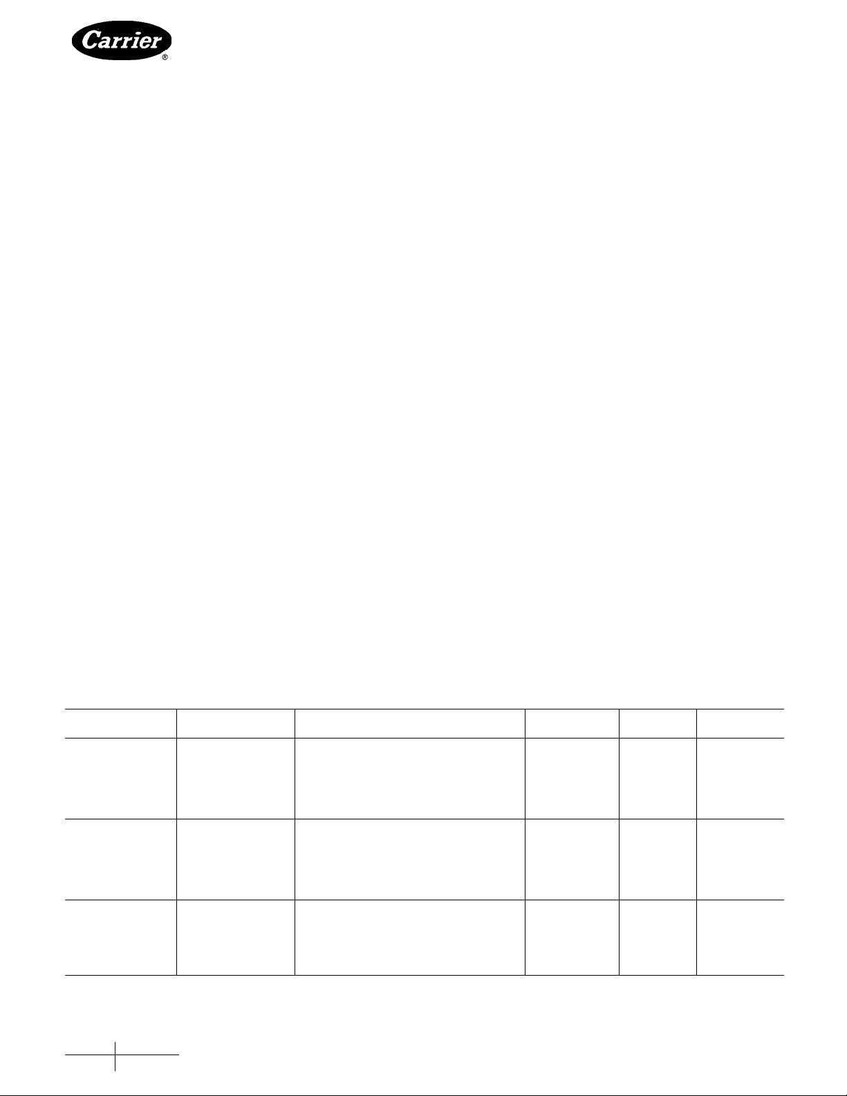
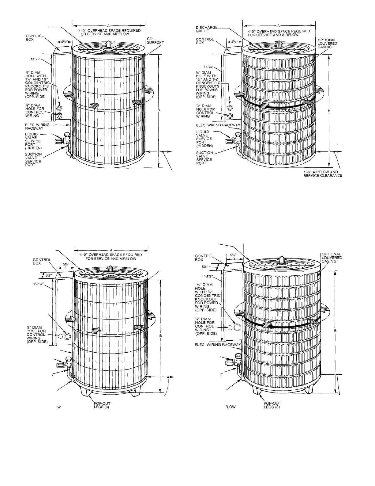
Cabinet — Certain maintenance routines and repairs
require removal of cabinet panels. All condensing units
and heat pump models of this series have same basic
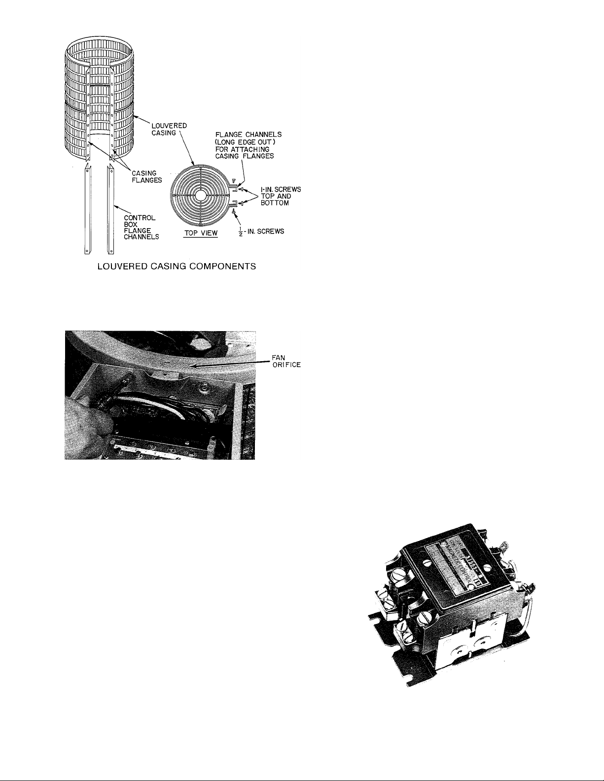
design with only minor differences. See Fig. 1.
REMOVING LOUVERED CASING — (See Fig. 2.)
1. Turn off all power to unit.
2. Loosen screws around circumference of fan orifice.
3. Remove screws around circumference of basepan.
4. Remove screws along control box support brackets.
5. Carefully remove louvered casing.
A CAUTION
Do not attempt to remove wire grille around coil.
Grille is integral part of coil structure and sup
ports coil.
REMOVING FAN ORIFICE — (See Fig. 3.)
1. Turn off all power to unit.
2. Remove screws holding grille on top of fan orifice.
3. Unplug wires from fan motor. Fan blades on certain
models may have to be removed. Refer to Service —
Electrical.
4. Remove screws holding fan orifice to wire grille and
control box.
5. Remove fan orifice.
ELECTRICAL BOX ACCESS — (See Fig. 1.)
1. Turn off all power to unit.
2. Remove screws holding box cover.
Page 4
DISCHARGE
GRILLE
BASIC CONDENSING UNIT
r-6" AIRFLOW AND
SERVICE CLEARANCE
ON 3 SIDES — 12" ON
REMAINING SIDE
ON 3 SIDES — 12" ON
REMAINING SIDE
LOUVERED CONDENSING UNIT
DISCHARGE
GRILLE
IVb" DIAM
HOLE
WITH 1%"
CONCENTRIC
KNOCKOUT
FOR POWER
WIRING
(OPP. SIDE)
ELEC. WIRING RACEWAY
LIQUID LINE
SERVICE PORT
ATSERVlOE
VALVE(CLG
CYCLE)
SUCTION
SERVICE PORT
AT SERVICE
VALVE(CLG
CYCLE)
SUCTION
SERVICE PORT
(HIDDEN)
COIL
SUPPORT
r-6" AIRFLOW AND
SERVICE CLEARANCE
ON 3 SIDES — 12" ON
REMAINING SIDE
DISCHARGE
GRILLE
LIQUID LINE
SERVICE PORT
AT SERVICEVALVE (CLG
CYCLE)
SUCTION
SERVICE POR
AT SERVICE
VALVE(CLG
CYCLE)
SUCTION
SERVICE PORT
(HIDDEN)
4'-0” OVERHEAD SPACE REQUIRED
FOR SERVICE AND AIRFLOW
r-6" AIRFLOW AND
SERVICE CLEARANCE
ON 3 SIDES —12" ON
REMAINING SIDE
BASIC HEAT PUMP UNIT
Fig. 1 — Condensing and Heat Pump Units
LOUVERED HEAT PUMP UNIT
Page 5
SCREWS
TOP COVER
BASEPAN FLANGE
C
Fig. 2 — Louvered Casing Assembly
Fig. 3 — Removing Orifice Fan
Electrical — Exercise extreme caution when work
ing on any electrical components. Shut off all power
to system prior to troubleshooting. Some trouble
shooting techniques require power to remain on. In
these instances, exercise extreme caution to avoid
danger of electrical shock. ONLY TRAINED SERVICE
PERSONNEL SHOULD PERFORM ELECTRICAL
TROUBLESHOOTING.
CONTACTORS — (See Fig. 4.) Contactor provides
means of applying power to unit using lower power
(24 v) from transformer in order to power the contactor
coil. Depending on unit model, you may encounter
single-, double- or triple-pole contactors to break power.
One side of the line may be electrically hot, so extreme
caution must be exercised when troubleshooting.
The contactor coil for these and most residential
models of condensing units and heat pumps is powered by
24 vac. If contactor does not operate:
1. With power off, check whether contacts are free to
move. Check for severe burning or arcing on contact
points.
ATTACHING CASING TO TOP COVER
AND BASEPAN
2. With power off, use ohmmeter to check for continuity
of coil. Disconnect leads before checking. A lowresistance reading is normal. Do not look for a specific
value as different part numbers used will have different
resistance values.
3. Reconnect leads and apply low-voltage power to
contactor coil. This may be done by leaving highvoltage power to outdoor unit off, and by turning
thermostat to heat or cool. Check voltage at coil with
voltmeter. Reading should be between 20 - 30 volts.
Contactor should pull in if voltage is correct and coil
is good. If contactor does not pull in, change
contactor.
4. With high-voltage power off and contacts pulled in,
check for continuity across contacts with ohmmeter.
A very low or zero resistance should be read. Higher
readings could indicate burned or pitted contacts
which may cause future failures.
Fig. 4 — Contactor
Page 6
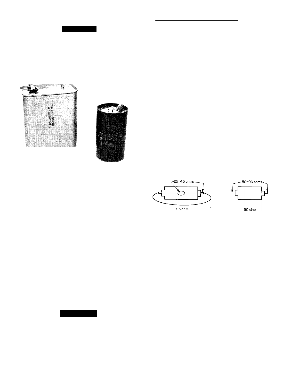
CAPACITORS — (See Fig. 5.)
A CAUTION
Capacitors can store electrical energy when power
is off. Electrical shock can result if you touch the
capacitor terminals and discharge this stored energy.
Exercise extreme caution when working near
capacitors. With power off, discharge stored energy
by shorting across the capacitor terminals with a
15,000-ohm, 2-watt resistor, or a screwdriver blade
with insulated handle.
Hard-Start Capacitors and PTC Devices — Sometimes,
under adverse conditions, a standard run capacitor in a
system is inadequate to start compressor. In these
instances, a start-assist device is used to provide an extra
starting boost to compressor motor. The first device is
called a PTC (positive temperature coefficient) or ther
mistor (see Fig. 6). It is a resistor wired in parallel with run
capacitor. As current flows through it at start-up, it heats
up. As it heats up, its resistance increases greatly, until
it effectively lowers current through it to an extremely
low value. This, in effect, removes it from the circuit.
After system shuts down, resistor cools and resistance
value returns to normal, until next time system starts.
Thermistor device is adequate for most conditions,
however, in systems where off cycle is short, device
cannot cool fully and becomes less effective as a start
device. It is an easy device to troubleshoot. Turn off all
power to system.
Check thermistor with ohmmeter as described below.
If indoor coil does not have a bleed-type expansion
device, it may be necessary to remove start thermistor
and replace with accessory start capacitor and relay.
Shut off all power to unit. Remove PTC from unit.
Wait at least 10 minutes for PTC to cool to ambient
temperature.
RUN CAPACITOR START CAPACITOR
Fig. 5 — Capacitors
Capacitors are used as a phase shifting device to aid in
starting certain single-phase motors. Check capacitors
as follows:
1. Always check capacitors with power off. Attempting
to troubleshoot a capacitor with power on can be
dangerous. Defective capacitors may explode when
power is applied. Insulating fluid inside is combustible
and may ignite, causing burns. After power is off,
discharge capacitors as outlined above. Disconnect
capacitor from circuit. Use ohmmeter, check each
terminal to ground (use capacitor case). Discard any
capacitor that shows resistance. Place ohmmeter leads
across capacitor and place on R x 10k scale. Meter
should jump to a low resistance value and slowly climb
to higher value. Eailure of meter to do this indicates
an open capacitor. If resistance stays at zero or a low
value, capacitor is shorted.
2. Capacitance testers are available which will read value
of capacitor. If value is not within ± 10% value stated
on capacitor, it should be changed. If capacitor is
not open or shorted, its capacitance value is calcu
lated by measuring voltage across capacitor and
current it draws.
A WARNING
Exercise extreme caution when taking readings
while power is on. Use following formula to
calculate capacitance:
^ . , r,. 2650 X amps
Capacitance (mfd) =
3. Remove any capacitor that shows signs of bulging,
dents or leaking. Do not apply power to a defective
capacitor as it may explode.
volts
Measure resistance of PTC with ohmmeter. Resistance
of 25-ohm PTC is measured between center tab and
end tab with jumper across 2 end terminals.
Fig. 6 — PTC Devices
The cold resistance (Rj) of any PTC device should be
approximately 100 - 180% of device ohm rating.
50-ohm PTC = 50 - 90 ohm resistance
25-ohm PTC = 25 - 45 ohm resistance
If PTC resistance is appreciably lower or more than
200% higher than rating, device is defective.
If thermistor is good and compressor does not start,
disconnect thermistor from starting circuit. Give com
pressor a temporary capacitance boost. Run compressor
for 10 minutes, shut off, allow system pressure to equal
ize. Reconnect start thermistor. Try restarting com
pressor without boost capacitor. If after 2 attempts,
compressor does not start, remove thermistor. Add an
accessory start capacitor relay package.
Temporary Capacitance Boost — (See Fig. 7.) There are
times when a temporary capacitance boost is needed to
get compressor started. Do not under any circumstances
attach temporary boost capacitor directly across com
pressor terminals. Serious personal injury can result.
Exercise extreme caution with this procedure when highvoltage power is on. If compressor motor does not start,
it may be due to low-line voltage, improper pressure
equalization or weak run capacitor. Check each possi
bility, attempt capacitance boosting before adding
auxiliary start capacitor and relay.
Page 7

220-V FROM UNIT
Fig. 7 — Capacitance Boosting
Turn off power. Check compressor for ground or open.
If there is none, proceed. Obtain a start capacitor
approved by compressor manufacturer. Connect wires
with insulated probes to each terminal. Touch probes to
each side of run capacitor. Energize and start compressor,
pull probes away after about 3 seconds. Discharge start
capacitor. Run compressor about 10 minutes. Stop and
allow to sit idle about 5 minutes. Check system pressure
equalization. Attempt to restart without capacitance
boost. If compressor does not start after several attempts,
add proper auxiliary start capacitor and relay.
If PTC thermistor device is inadequate as start device,
a start capacitor and relay may be added to system to
insure positive start. Capacitor is wired in parallel with
run capacitor through normally closed set of contacts on
a device called start relay. The relay coil is wired across
start and common terminals of cornpressor. The added
capacitance gets compressor started. As compressor
comes up to speed, voltage across start and common
terminals increases to a value high enough to cause start
relay to energize. This opens normally closed contacts
and removes start capacitor from circuit. In actual
practice, this occurs in a fraction of a second.
To check start relay and capacitor, first turn off all
power to unit. Discharge start and run capacitors as
outlined earlier. Most start capacitors will have a 15,000ohm, 2-watt bleed resistor. Disconnect these devices from
system. Start capacitor can be inspected visually. It is
designed for short duration or intermittent duty. If left in
circuit for prolonged period it blows through a specially
designed orifice. If it appears blown, check for stuck
contacts in start relay. Start capacitor can be checked
by ohmmeter method discussed earlier.
A CAUTION
If bleed resistor is wired across start capacitor, it
must be disconnected to avoid erroneous readings
when ohmmeter is applied across capacitor.
Start relay is checked with ohmmeter. Check for
continuity across coil of relay. You should encounter a
high resistance. Since relay contacts are normally closed,
you should read low resistance across them.
Both PTC device and capacitor relay start system are
standard equipment on some of these units. They are also
available as accessories and may be field installed.
TIME GUARD II — (See Fig. 8.)
Description — Solid-state Time Guard device protects
unit compressor by preventing short cycling. After a
system shutdown. Time Guard provides for a 5 ± 2minute delay before compressor restarts. On normal
start-up, 5-minute delay occurs before thermostat closes.
After thermostat closes. Time Guard device provides a
3-second delay to prevent contactor chattering.
Time Guard 11 device is simple to troubleshoot. Only a
voltmeter capable of reading 24 v is needed. Device is
in control circuit, therefore, troubleshooting is safe with
control power (24 v) on and high-voltage power off.
With high-voltage power off, attach voltmeter leads
across T1 and T3, set thermostat so that Y terminal is
energized. Make sure all protective devices in series with
Y terminal are closed. Voltmeter should read 24 v across
T1 and T3. With 24 v still applied, move voltmeter lead
from T1 terminal to T2 terminal. After 5 ± 2 minutes,
voltmeter should read 24 v, indicating control is
functioning normally. If no time delay is encountered,
or device never times out, change control. A schematic
diagram printed on device enables you to troubleshoot
this device.
CRANKCASE HEATER — Crankcase heater is a device
for keeping compressor oil warm. By keeping oil warm,
refrigerant does not migrate to and condense in com
pressor shell. This prevents flooded starts which can
severely damage compressor.
Crankcase heaters come in 2 basic types, wraparound
(belly-band) type that is wrapped externally around
compressor shell, and insertion type that is inserted into
compressor oil well in shell of compressor. Both types
are in this family of units.
Crankcase heater is powered by high-vo\tagt power of
unit. Use extreme caution troubleshooting this device
with power on. Easiest method of troubleshooting is to
apply voltmeter across crankcase heater leads to see if
heater voltage is on. Carefully feel area around crankcase
heater. If warm, crankcase heater is probably function
ing. Do not rely on this method as absolute evidence
heater is functioning. If compressor has been running,
area will still be warm.
With power off, and heater leads disconnected, check
across leads with ohmmeter. Do not look for a specific
resistance reading. Check for resistance or an open
circuit. Change heater if an open circuit is detected.
Some crankcase heaters in this series of units are
equipped with crankcase heater switch installed in series
with heater. This energy-saving device shuts off power to
heater when temperatures are high enough that heater
is not needed. Be sure this switch is functioning normally
before condemning crankcase heater.
PRESSURE SWITCHES — Pressure switches are pro
tective devices wired into control circuit (low voltage).
They shut compressor off if abnormally high or low
pressures are present in refrigeration circuit. Depending
on unit model, you may find a low- or high-pressure
switch, or both, in system.
Low-Pressure Switch — Located on suction line, protects
against low suction pressures caused by such events as
loss of charge, low airflow across indoor coil, dirty
filters, etc. It opens on a pressure drop at about 30 psi.
If system pressure is above this, switch should be closed.
To check switch, turn off all power to unit, disconnect
leads on switch, apply ohmmeter leads across switch.
You should have continuity on a good switch. Because
these switches are attached to refrigeration system under
pressure, it is not advisable to remove this device for
troubleshooting unless you are reasonably certain that a
problem exists. If switch must be removed, bleed all
system charge so that pressure gage reads 0 psi.
Page 8

ACCESSORY TIME GUARD II DEVICE
-CONTROL
BOX
3
Tl
Т2
SEC
BLK DENOTES CLOSED CONTACTS
TIME GUARD II SEQUENCE CHART
OPERATING
TIME
CUT YELLOW WIRE
5MIN-
NOTE: When accessory Time Guard II is used with accessory Service Sentry control on
38QH,QN,QS units, refer to wiring instructions packed with Service Sentry control.
MOUNTING ACCESSORY TIME GUARD II
ON MODEL 38QH,QS,QN
Fig. 8 — Solid-State Time Guard II Description
A CAUTION
Wear safety glasses and gloves when working with
refrigerants. Apply heat with a torch to solder joint
and remove switch. Wear safety glasses when using
torch. Have quenching cloth available. Oil vapor in
line may ignite when switch is removed.
Braze in 1 / 4-in. flare fitting and screw on replacement
pressure switch. Wear safety glasses, observe all safety
precautions.
High-Pressure Switch — Located on discharge line,
protects against high discharge pressures caused by such
events as overcharge, condenser fan motor failure, system
restriction, etc. It opens on pressure rise at about 425 psi.
If system pressures go above this setting during abnormal
condition, switch opens. Do not attempt to simulate
these system abnormalities, as high pressures pose a
serious safety hazard. High-pressure switch is also
checked with an ohmmeter similar to checking low-
pressure switch. If system pressure is below 425 psi, switch
shows continuity. It is replaced in same manner as lowpressure switch. Observe all safety precautions.
TIME GUARD II CONTROL WIRING
CONNECTIONS FOR 38QH,QN,QS UNITS
Liquid Line Pressure Switch — Located on liquid line,
used in heat pump only. Function is similar to con
ventional low-pressure switch. Because heat pumps
experience very low suction pressures during normal
system operation, a conventional low-pressure switch
cannot be installed on suction line. Switch is installed
in liquid line instead and acts as loss-of-charge protector.
It operates identically to low-pressure switch except it
opens at 5 psi. Troubleshooting and removing this switch
is identical to procedures used on other switches. Observe
same safety precautions.
DEFROST THERMOSTATS — Defrost thermostat
signals heat pump that conditions are right for defrost or
that conditions have changed to terminate defrost. It is a
thermally actuated switch clamped to liquid line to sense
its temperature. Normal temperature range is: closed at
27 - 5 F, open at 80 ± 5 F.
Since defrost thermostat is the heart of the defrost
system, its troubleshooting procedure is described below.
PRINTED-CIRCUIT CONTROL BOARD — Solidstate defrost control used on 38QH,QN,QS heat pumps
replaces electro-mechanical timer and defrost relay found
on previous Carrier Chronotemp^“ defrost systems. De
frost control board can be set to check need for defrost
Page 9

every 30, 50 or 90 minutes of operating time. Control
board has additional feature that allows unit to restart in
defrost cycle if room thermostat is satisfied during
defrost.
Troubleshooting defrost control involves a series of
simple steps that indicate whether board is defective.
NOTE: Procedure allows mechanic to check control
board and defrost thermostat for defects. First, trouble
shoot to make sure unit operates properly in heating and
cooling modes. This ensures problems are not attributed
to the defrost control board. Additional steps follow:
1. Turn thermostat to OFF. Disconnect all power to
outdoor unit.
2. Remove control box cover for access to electrical
components and defrost control board.
3. Disconnect defrost thermostat leads from control
board, connect to ohmmeter. Thermostat leads are
the heavy-gage black insulated wires connected to
DFT and C terminals on control board. Resistance
reading may be 0 (indicating closed defrost thermo
stat) or infinity ( oo for open thermostat) depending
on outdoor temperature.
4. Jumper between DFT and C terminals on control
board as shown in Fig. 9.
Fig. 10 — Inserting Jumper Wire
into Protective Cover
5. Disconnect outdoor fan motor lead. Tape lead to
prevent grounding.
6. Restart unit in heating, allowing frost to accumulate
on outdoor coil.
7. After a few minutes in heating, liquid line tempera
ture should drop below closing set point of defrost
thermostat. Using ohmmeter, check resistance across
defrost thermostat leads. Resistance of 0 indicates
defrost thermostat is closed and operating properly.
8. Remove protective cover from TPl and TP2 speed
up terminals. Insert jumper wire into protective
cover, reinsert protective cover on speed-up termi
nals. This reduces by 1 / 4 timing sequence of original
time (see Fig. 10). Since Fig. 10 shows timing cycle set
at 30 minutes, unit initiates defrost within approxi
mately 30 seconds; if setting is at 50 minutes, within
50 seconds; 90 minutes, within 90 seconds. When you
hear reversing valve change position, remove protec
tive cover/jumper, otherwise control will terminate
normal 10-minute defrost cycle in approximately
10 seconds.
A CAUTION
Do not use screwdriver or other means to short
speed-up pins. If pins are accidentally grounded,
control board is destroyed.
9. Unit is now operating in defrost mode. Using volt
meter, check between R and W2 as shown in Fig. 11.
Fig. 11 — Checking Between R and W2
Page 10

Reading on voltmeter should indicate zero volts.
This step ensures defrost relay contacts have closed,
energizing supplemental heat and reversing valve
solenoid.
10. Unit should remain in defrost no longer than 10
minutes. Actual time in defrost depends on how
quickly speed-up jumper is removed. If it takes 3
seconds to remove speed-up jumper after unit has
switched to defrost, only 7 minutes of defrost cycle
remains.
11. After a few minutes in defrost (cooling) operation,
liquid line should be warm enough to have caused
defrost thermostat contacts to open. Check resistance
across defrost thermostat. Ohmmeter should read
infinite resistance, indicating defrost thermostat
has opened.
12. Shut off unit power and reconnect fan lead.
13. Remove jumper wire from speed-up terminal pro
tective cover and reinsert cover on speed-up termi
nals. Failure to remove jumper causes unit to speed
up operating cycles continuously.
14. Remove jumper between DFT and C terminals.
Reconnect defrost thermostat leads.
15. Replace control box cover. Restore power to unit.
If defrost thermostat does not check out following
above steps or incorrect calibration is suspected, check
for a defective thermostat as follows:
1. Follow steps 1 - 5 above.
2. Using thermocouple temperature measuring device,
route sensor or probe underneath coil (or other
convenient location). Attach to liquid line near defrost
thermostat. Insulate for more accurate reading.
3. Restart unit in heating.
4. Within a few minutes, liquid line temperature drops
within a range causing defrost thermostat contacts to
close. Temperature range is from 32 F to 22 F. Notice
temperature at which ohmmeter reading goes from
oc to 0 ohms. Thermostat contacts close at this point.
5. Remove protective cover from TP 1 and TP2 speed-up
terminals, insert jumper wire into protective cover,
reinsert protective cover on the speed-up terminals.
6. Unit changes over to defrost within 90 seconds
' (depending on timing cycle setting). Liquid line tem
perature rises to range where defrost thermostat
contacts open. Temperature range is from 75 F to
85 F. Resistance goes from 0 to oc when contacts open.
7. If either opening or closing temperature does not fall
within above ranges, or thermostat sticks in one
position, replace thermostat to ensure proper defrost
operation.
COLOR-CODED
TERMINAL BLOCK
Fig. 12 — Removing Outdoor Fan Motor
motor with 32 drops (16 drops per hole) of SAE 10 non
detergent oil at intervals described below:
a. Annually, when environment is very dirty, ambient
temperature is higher than 105 F (40 C), and average
unit operating time exceeds 15 hours a day.
b. Every 3 years, when environment is reasonably clean,
ambient temperature is less than 105 F (40 C) and unit
operating time averages 8 to 15 hours a day.
c. Every 5 years, when environment is clean, ambient
temperature is less than 105 F (40 C) and unit oper
ating time averages less than 8 hours a day.
After motor is lubricated, be sure fan prop is positioned
correctly on motor shaft. See Fig. 13.
DISCHARGE GRILLE
Fig. 13 — Condenser Fan Position
FAN MOTORS (See Fig. 12.) Fan motor powers fan
that draws air through outdoor coil to perform heat
exchange. Motors are totally enclosed to increase reli
ability. This also eliminates need for rain shield. Motors
are provided with color-coded terminal block to facilitate
removal. Oilers are provided on motor bearings. Adhere
to following schedule for fan motor lubrication.
A CAUTION
Turn off all power to unit before servicing or replac
ing fan motor.
Fan Motor Bearings — Oiling holes are provided at each
end of condenser fan motor. Remove fan motor, lubricate
Fan motors should present no problem in trouble
shooting. A motor with seized or tight bearings can
sometimes be saved or have its life extended by adding
oil to the bearings.
A CAUTION
Be sure unit main power switch is turned off. Failure
to do so may result in electric shock, or injury from
rotating fan blade.
For suspected electrical failures, check for loose or
faulty electrical connections, or defective fan motor
10
Page 11

capacitor. Fan motor is equipped with thermal overload
device in motor windings which may open under adverse
operating conditions. Allow time for motor to cool so
device can reset. Further checking of motor can be done
with an ohmmeter. Set scale on R x 1 position, check
for continuity between 3 leads. Replace motors that show
an open circuit in any of the windings. Place one lead of
ohmmeter on each motor lead. At same time, place
other ohmmeter lead on motor case (ground). Replace
any motor that shows resistance to ground. Obviously
any motor that shows signs of arcing, burning or over
heating should be suspect and replaced.
SERVICE SENTRY CONTROL BOARD — Service
Sentry control provides immediate warning when out
door heat pump requires servicing. It turns on indoor
thermostat light if compressor doesn’t operate for either
heating or cooling. This enables owner to obtain speedy
heat pump service during heating season, reducing
supplementary electric heat costs, and during cooling
.season, reducing period of heat discomfort. Fig. 14.
Refer to Fig. 15 for wiring connections when Service
Sentry and solid-state Time Guard II accessories are used.
The Service Sentry is an accessory device. On heat
pump DL and CD option packages, a slightly different
version of Service Sentry is installed as standard equip
ment. It functions almost identically to accessory Service
Sentry except that it locks out compressor under certain
adverse operating conditions. System is manually reset by
shutting it off at thermostat subbase, then turning it back
on. If adverse condition is corrected, system restarts.
One example of an adverse condition would be if
system is located in a desert climate where high operating
temperatures may cause system to shut down on the highpressure switch, or on the compressor internal overload.
Service Sentry Requires 2 Inputs:
1. It must sense a 24-v input from thermostat. As thermo
stat calls for heating or cooling, it supplies 24 v to
Service Sentry device.
2. A current transformer (or induction loop) similar to
a clamp-on ammeter senses current draw in the com
pressor lead. Induction loop must sense a minimum
current draw when thermostat is calling for heating
or cooling.
NOTES:
1. On a single-phase compressor, induction loop senses
current in common leg.
2. On a 3-phase compressor, induction loop senses
current in one of the pha.ses.
Troubleshooting Service Sentry device is easy. With
thermostat calling for heating or cooling and compressor
running, indoor thermostat light should be off If on,
check for wiring errors or replace the Service Sentry.
To check for correct operation, shut off circuit breaker
or disconnect switch to outdoor unit while it is running.
Signal light on thermostat should light. If this does not
occur, check for wiring errors or replace the Service
Sentry.
Fig. 14 — Service Sentry Control
Use Service Sentry control with single-phase Carrier
heat pumps equipped with 24-v control circuit.
Connect black, orange and red pigtails (24 v) on Service
Sentry to outdoor unit control circuit terminal board.
See Fig. 15 and wiring diagram on unit. An extra control
wire is required between L terminals on outdoor unit,
indoor unit and thermostat subbase (the L terminal is
currently being added to outdoor and indoor unit termi
nal blocks). If units do not already have L terminal, splice
control wire between L terminals on Service Sentry and
thermostat subbase. Terminal L is labeled terminal X
on some thermostat subbases (all future subbases will
read terminal L).
Connect all field line power wires to unit in usual
manner. However, route one field line power supply wire
through metallic loop on bottom of Service Sentry, then
to normal unit connection. On 015 (230-1-60) and
018 (230-1-60) units, pass supply wire through metallic
loop twice, as shown in Fig. 14 and 15. On all other units,
pass supply wire through loop only once.
A CAUTION
If Service Sentry needs replacing, shut off all power
to unit before attempting repairs.
OUTDOOR THERMOSTATS — (See Fig. 16.) Out
door thermostat brings on stages of electric heat as out
door temperature and heat pump output drops. Setting
at which thermostat closes is variable, depending on
design of system. It is .set at time of installation and should
not be changed without good reason. Up to 2 outdoor
thermostats may be installed. Some systems may not
have any thermostat.
Although these devices are installed in control circuit
(24 v), turn off all power to unit before attempting to
troubleshoot thermostat.
Use a standard ohmmeter to check for continuity
through thermostat. If you suspect thermostat is out of
calibration, use calibrated electronic thermometer to
determine correct outdoor temperature. Insert a screw
driver blade in adjustment slot and turn thermostat
switch until it closes. Observe this using ohmmeter across
switch. Read temperature setting when switch clo.ses. It
should be close to reading observed using electronic
thermometer. Any setting within ± 5 degrees is
acceptable.
11
Page 12

24-VOLT WIRING
LINE VOLTAGE
*
P
c
PASS SUPPLY WIRE THRU
METALLIC LOOP TWICE ON
UNITS WITH NAMEPLATE
RLA OF 14 AMPS OR LESS
SUPPLY WIRE
07
THERMOSTAT
SUBBASE
FIELD LINE VOLTAGE SUPPLY WIRE
INDOOR UNIT
TERMINAL
BOARD
OUTDOOR UNIT
TERMINAL
BOARD
C — Contactor
LLPS — Liquid Line Low-Pressure Switch
TB — Terminal Board
Common Potential
Factory Wiring (field connected)
_____
Field-Supplied Wiring
Fig. 15 — Wiring Connections for Service Sentry and Solid-State Time Guard II
>TB
Compressor — The compressor is the heart of the
refrigeration system. It pumps refrigerant through the
system. If it malfunctions, the whole system suffers.
The compressor is an electrical (as well as mechanical)
device. Extreme caution should be exercised when work
ing near compressors. Power should be shut off, if
possible, for most troubleshooting techniques. Refrig
erants in system present other safety hazards.
Always
wear safety glasses and gloves when handling refrigerants.
Compressor failures are classified in 2 broad failure
categories, mechanical and electrical. Both types are
discussed below and on page 13.
MECHANICAL FAILURES — Compressor is a
mechanical pump driven by an electric motor contained
in a welded or hermetic shell. In a mechanical failure,
motor or electrical circuit appears normal, but com
pressor does not function normally.
12
Page 13

NOTES:
1. Affix capillary and bulb on outside of grille wire nearest control box.
2. Secure bulb to grille with wire ties or suitable fastener.
3. If necessary, shield bulb from direct sunlight using appropriate material.
Fig. 16 — Outdoor Thermostat Installation
A CAUTION
Exercise extreme caution when reading compressor
currents, as high-voltage power is on. Correct any of
the problems described below before installing and
running a replacement compressor. Wear safety
glasses and gloves when handling refrigerants.
Locked Rotor — In this type of failure, compressor
motor and all starting components are normal. When
compressor attempts to start, it draws locked rotor
current and cycles off on the internal protection. Locked
rotor current is measured by applying a clamp-on
ammeter around common lead of the compressor on a
single-phase compressor, or any one of the leads on a
3-phase compressor. Then measure current it draws when
it attempts to start. LRA (locked rotor amp value) is
stamped on compressor nameplate.
If compressor draws locked rotor amps, and all other
external sources of problems have been eliminated,
compressor must be changed. Because compressor is a
sealed unit, it is impossible to determine exact mechanical
failure. However, complete system should be checked for
abnormalities such as incorrect refrigerant charge,
restrictions, insufficient airflow across indoor or outdoor
coil, etc., which could be contributing to the failure.
Runs, Doesn't Pump — In this type of failure, compres
sor motor runs and turns compressor, but compressor
does not pump the refrigerant. A clamp-on ammeter on
common leg of a single-phase compressor, or any one
lead of a 3-phase compressor, shows a very low current
draw, much lower than RLA (rated load amps) value
stamped on compressor nameplate. Because no refrig
erant is being pumped, there is no return gas to cool
compressor motor. It eventually overheats and shuts off
on its internal protection.
Runs — Doesn’t Pump, High-To-Low Side Leak — This
failure is similar to previous one except compressor is
pumping. Usually, an internal problem such as blown
head gasket or broken internal discharge line causes
compressor to pump hot discharge gas back into its own
shell rather than through system.
Using pressure gages on service valves shows high
suction and low discharge pressure readings. Motor
currents are lower than normal. Because hot gas is being
discharged into shell, the shell becomes hot. The hot
gas causes compressor motor to cycle off on its internal
protection.
Runs and Pumps, Low Capacity — This failure type is
difficult to pinpoint because extent of damage varies.
Compressor is a pump with internal valves that enable
compressor to pump properly. On multicylinder com
pressors, each cylinder has a complete set of suction and
discharge valves. Any of these parts may become
damaged or broken causing loss in pumping capacity.
Severity of damage determines amount of capacity loss.
Use pressure gages to find any abnormal system pressures
if system charge and other conditions are normal.
An owner may complain that a unit is not handling the
building’s heating or cooling load. The compressor
current draw may be abnormally low or high. Although
this type of failure does occur, all other possible causes of
capacity loss must be eliminated before condemning
compressor.
Noisy Compressor— May be caused by variety of internal problems such as loosened hardware, broken
mounting springs, etc. May also be caused by system
problems. Overcharging a compressor causes operating
noise, particularly at start-up. Certain single-cylinder
compressors are noisy at start-up and may operate
noisily. Too much oil in compressor may cause noise.
Normally this problem is encountered only after a
replacement compressor has been added, without purging
oil from previous compressor. As new compressor
pumps, excess oil in system returns and adds to volume
already present, causing noise.
Compressor Leaks — Sometimes a leak is detected at
weld seam around girth of compressor, or a fitting that
joins compressor shell. Many of these leaks can be re
paired and the compressor saved if correct procedure is
followed. Turn off all power to unit. Remove all refrig
erant from system so that gage pressure is 0 psi. Use safety
glasses and gloves when handling refrigerants. Clean area
around leak to bare metal. Apply flux and repair joint
with silver solder.
Do not use low-temperature solder
such as 50-50. Clean off excess flux, check for leaks, and
apply paint over repaired area to prevent corrosion.
Do not use this method to repair a compressor leak due
to severe corrosion. Never attempt to repair a compressor
leaking at electric terminals. This type of failure requires
compressor replacement.
ELECTRICAL FAILURES — The compressor me
chanical pump is driven by an electric motor within
hermetic shell. In electrical failures, compressor does not
run although external electrical and mechanical systems
appear normal. Compressor must be checked electrically
for abnormalities.
Before troubleshooting compressor motor, review this
description of compressor motor terminal identification.
Single-Phase Motors — See Fig. 17. To determine ter
minals C, S, and R: Turn off all unit power. Short the run
(and start) capacitor to prevent shock. Remove all
wires from motor terminals. Using an ohmmeter on
0-10 ohm scale, read resistance between all pairs of
terminals. Determine 2 terminals that provide greatest
resistance reading. Through elimination, remaining
13
Page 14

(example)
TO DETERMINE INTERNAL CONNECTIONS OF SINGLE
PHASE MOTORS (C,S,R) except shaded-pole
Deduction:
©—(D
J OHM METER
0-10 ÍÍ SCALE
Ф
5.2 Í1
0.6 Í!
é
(Ь
Fig. 17 — Determining Internal Connections
terminal must be common (C). Greatest resistance
between common (C) and another terminal indicates
start winding because it has more turns. This terminal is
start (S). Remaining terminal will be run winding (R).
NOTE: If there is an internal line break protector, it
must be closed.
Three-Phase Motors — See Fig. 18. Resistance readings
between all 3 sets of windings should be the same.
All compressors are equipped with internal motor pro
tection. If motor becomes hot for any reason, protector
opens. Compressor should always be allowed to cool
and protector to close before troubleshooting. Always
turn off all power to unit and disconnect leads at com
pressor terminals before taking readings.
Most common motor failures are due to either an open,
grounded or short circuit. Directions below are specifi
cally for single-phase units, however, they also apply to
3-phase compressors. When a single-phase compressor
fails to start or run, 3 tests can help determine the
problem. First, all possible external causes should be
eliminated, such as overloads, improper voltage, pressure
equalization, defective capacitor(s), relays, wiring, etc.
If compressor has internal line break overload, be sure
it is closed.
@@ (smallest resistance)
(3)—@ (remaining resistance)
5.8 Í1
(greatest resistance)
5.8il (ohm)
0.611
5.211
Run Winding (R)
Start Winding (S)
(2) is common (C)
by elimination
(2) is common,
therefore (T) is
Start Winding (S)
(J) is Run Winding (R)
Ground Circuit — To determine if a wire has broken or
come in direct contact with shell, causing a direct short
to ground: Be sure all power is off. Discharge all capaci
tors. Remove wires from terminals C, S and R. On
hermetic compressors, allow crankcase heaters to remain
on for several hours before checking motor to ensure
windings are not saturated with refrigerant. Use an
ohmmeter on R x 10,000 ohm scale. A megohmmeter
may be used in place of ohmmeter (follow manufacturer’s
instructions). Place one meter probe on ground or on
compressor shell. Make a good metal-to-metal contact.
Place other probe on terminals C, S and R in sequence.
Note meter scale. If reading of zero or low resistance is
obtained, motor is grounded. Replace compressor.
A compressor of one-ton capacity or less is probably
grounded if resistance is below one million ohms. On
larger size single-phase compressors, resistance to ground
should not be less than 1000 ohms per volt of operating
voltage.
Example:
230-1-60 ... 230 X 1000 = 230,000 ohms minimum.
Open Circuit — To determine if any winding has a break
in the internal wires and current is unable to pass through:
Be sure all power is off. Discharge all capacitors. Remove
wires from terminals C, S and R. Use an ohmmeter on
0-1000 ohm scale to check resistance from C-R, C-S
and R-S. Because winding resistances are usually less
than 10 ohms, each reading appears to be approximately
zero ohm. If resistance remains at 1000 ohms, an open or
break exists and compressor should be replaced.
Short Circuit — To determine if any wires within
windings have broken through their insulation and made
contact with other wires, thereby shorting all or part of
the winding(s): First, be sure the following conditions
are met:
1. Correct motor winding resistances must be known
before testing, either from previous readings or from
manufacturer’s specifications.
2. Temperature of windings must be as specified, usually
about 70 F.
3. Resistance measuring instrument must have an accu
racy within ± 5% - 10%. This requires accurate
ohmmeter (such as a Wheatstone bridge or null
balance-type instrument).
4. Motor must be dry or free from direct contact with
liquid refrigerant.
Make This Critical Test — (Not advisable unless above
conditions are met.) Be sure all power is off. Discharge all
capacitors. Remove wires from terminals C, S and R.
Place instrument probes together, determine probe and
lead wire resistance. Check resistance readings from C-R,
C-S and R-S. Subtract instrument probe and lead
14
Page 15

resistance from each reading. If any reading is within
± 20% of known resistance, motor is probably normal.
Usually a considerable difference in reading is noted if a
turn-to-turn short is present.
SYSTEM CLEAN-UP AFTER BURN-OUT
A CAUTION
Turn off all power to unit before proceeding. Wear
safety glasses and gloves when handling refrigerants.
Acids formed as a result of motor burn-out can
cause burns.
Some compressor electrical failures can cause motor
to burn. When this occurs, byproducts of burn, which
include sludge, carbon and acids contaminate system.
If burn-out is severe enough, system must be cleaned
before replacement compressor is installed. The 2 types
of motor burn-out can be classified as mild or severe.
In mild burn-out, there is little or no odor detectable.
Compressor oil is clear or slightly discolored. An acid
test of compressor oil will be negative. This type of failure
is treated the same as mechanical failure. Liquid line
strainer should be removed and liquid line filter drier
installed.
In a severe burn-out, there is a strong, pungent, rotten
egg odor. Compressor oil is very dark. Evidence of burn
ing may be present in tubing connected to compressor.
An acid test of compressor oil will be positive. Complete
system must be reverse-flushed with refrigerant. Accu-
RateT“ or TXV must be cleaned or replaced. In a heat
pump, accumulator and reversing valve are replaced.
These components are also removed and bypassed during
reverse-flushing procedure. Remove and discard liquid
line strainer. After system is reassembled, install liquid
and suction line filter driers, run system for 2 hours.
Discard both driers, install new liquid line drier only.
line and enters metering device at indoor coil. As it passes
through metering device, it becomes a gas-liquid mixture.
As it passes through indoor coil, it absorbs heat and
refrigerant is again changed to gas. The gas is returned
to compressor, where it is compressed to a hot gas, and
cycle repeats.
In a heat pump (see Fig. 19), the basic cycle is the same.
Reversing valve in system decides which coil, indoor or
outdoor, becomes evaporator or condenser. In heating
mode, indoor coil is condenser. It rejects heat into the
home after heat is absorbed by outdoor evaporator coil.
Thus, home is heated.
In cooling cycle, indoor coil becomes evaporator. It
absorbs heat from home and rejects it out-of-doors
through outdoor condenser coil. Thus, home is cooled.
A unique feature of the heat pump is that metering
devices are designed to meter refrigerant in one direction
of flow, and allow refrigerant to pass unhindered in other
direction. If indoor metering device is metering refrig
erant, outdoor device bypasses refrigerant and vice versa.
This allows both coils to serve a dual function.
HEATING CYCLE
INDOOR COIL
ACCUMULATOR
DISCHARGE SERVICE
PORTAT SERVICE
VALVE (HTG CYCLE)
HEAT PUMP
STRAINER
ACCURATER'™
(BYPASSING)
ACCESSORY
FILTER DRIER
(DUAL FLOW)
/SUCTION \ STRAINER
SERVICE \ OUTDOOR
PORT LIQUID LINE COIL
COMPRESSOR REMOVAL AND REPLACEMENT
— Once it is determined that compressor has failed and
the reason established, compressor must be changed.
Shut off all power to unit. Remove all refrigerant
from system until pressure gage reads 0 psi.
A CAUTION
Wear safety glasses and gloves when handling refrig
erants. Disconnect electrical leads from compressor.
Disconnect or remove crankcase heater. Remove
compressor holddown bolts.
Cut compressor from system with tubing cutters. Do
not use brazing torch for compressor removal. Oil vapor
may ignite when compressor is disconnected. Scratch
matching marks on stubs in old compressor. Make
corresponding marks on replacement compressor. Use
torch to remove stubs from old compressor and to re
install them in replacement compressor. Use copper
couplings to tie compressor back into system. Wear safety
glasses when using brazing torch. Evacuate system,
recharge, check for normal system operation.
Refrigeration System
REFRIGERATION CYCLE — In a refrigerant system,
refrigerant moves heat from one place to another. It is
useful to understand flow of refrigerant in a system.
In a straight cooling system, compressed hot gas leaves
compressor and enters condensing coil. As gas passes
through condenser coil it rejects heat and condenses into
liquid. The liquid leaves condensing unit through liquid
□ O OoQ
□ o Onn
o o
STRAINER
(METERING)
LIQUID LINE SERVICE PORT
AT SERVICE VALVE (CLG CYCLE)
COOLING CYCLE
INDOOR COIL
ACCUMULATOR
SUCTION SERVICE
PORT AT SERVICE
VALVE (CLG CYCLE)
HEAT PUMP
ACCESSORY
FILTER DRIEF
(DUAL FLOW)ACCU RATER
ACCURATER
(BYPASSING)
OUTDOOR
LIQUID LINE
PRESSURE SWITCH
COIL
Fig. 19 — 38QN Heat Pump
Refrigerant Flow Diagrams
LEAK DETECTING — (See Fig. 20.) New installations
should be checked for leaks prior to complete charging.
A CAUTION
Always wear safety glasses and gloves when handling
refrigerants.
15
Page 16

Fig. 20 — Leak Detector
If a system has lost all or most of its charge, system
must be pressurized again, up to approximately 1501b
minimum. This can be done by adding refrigerant, using
normal charging procedures. Or, it may be pressurized
with nitrogen (less expensive than refrigerant). Nitrogen
also leaks faster than R-22 and is not absorbed by refrig
eration oil. Nitrogen cannot, however, be detected by
leak detector.
gage ports for measuring system pressures, and provide
shutoff convenience for certain types of repairs.
Vapor line on all units and liquid line on condensing
units are connected to service valves by means of
Compatible Fitting. This mechanical-type fitting is also
used as a sweat fitting. Connections are made as follows:
Fig. 21 — Service Valves
COMPATIBLE FITTING
A CAUTION
Due to explosive pressures of nitrogen, it should
never be used without a pressure regulator on
the tank.
On the other hand, leaks in a system pressurized with
refrigerant can be spotted with a leak detector which
detects extremely small refrigerant leaks. This discussion
assumes that system is pressurized with either all refrig
erant or a mixture of nitrogen and refrigerant.
If system has been operating for some time, make first
check for a leak visually. Since refrigerant carries a small
quantity of oil, traces of oil at any joint or connection is
an indication the refrigerant is leaking at that point.
A simple and inexpensive method of testing for leaks is
to use soap bubbles. Any solution of water and soap
may be used.
Soap solution is applied to all joints and connections
in system. A small pinhole leak is located by tracing
bubbles in soap solution around leak.
Electronic leak detectors are now available for check
ing for leaks. These unquestionably represent the most
efficient and easiest method for checking for leaks.
There are various types of electronic leak detectors.
Generally speaking, they are all portable, most are light
weight, and consist of a box with several switches and a
probe or sniffer. Detector is turned on and probe is passed
around all fittings and connections in system. Leak is
detected by either a movement of a pointer on detector
dial, by a buzzing sound or a light.
In all instances, when a leak is found, system charge
must be hied down and leak repaired before final charging
and operation. After leak is repaired, evacuate system,
and correct refrigerant charge.
SERVICE VALVES (See Fig. 21.) Service valves pro
vide means for holding original factory charge in outdoor
unit prior to hookup to indoor coil. They also contain
Fig. 22 — Carrier Compatible Fitting
CARRIER COMPATIBLE FITTING — (See Fig. 22.)
Mechanical Connection to Compatible Fitting — (Mate
one set of connections at a time.)
1. Loosen nut on Compatible Fitting one turn. Do not
remove.
2. Remove plug, be sure 0-ring is in groove inside
Compatible Fitting.
3. Cut tubing to correct length. Deburr and size properly,
4. Insert tube into Compatible Fitting until it bottoms.
5. Tighten nut until it bottoms on shoulder of fitting.
Keep tube bottomed in Compatible Fitting while
tightening nut.
Sweat Connection to Compatible Fitting — (Use refrigerant grade tubing.)
1. Remove locking nut, rubber 0-ring and Schrader
core from valve.
2. Cut tubing to correct length. Deburr and size properly.
3. Insert tube into Compatible Fitting.
NOTE: Wrap top and bottom of service valves in wet
cloth to prevent damage by heat. Solder with lowtemperature 430 F (221 C) silver alloy solder.
4. Replace Schrader core.
5. Evacuate or purge system with field-supplied
refrigerant.
16
Page 17

This type of fitting is easily repaired if leaks develop.
2. Frontseat liquid line valve.
3. Start unit in cooling mode. Run until suction pressure
reaches 5 psig (35 kPa).
4. Shut unit off. Frontseat suction valve.
5. Vent remaining pressure to atmosphere.
Frontseat outdoor section service valves after relieving
refrigerant pressure in system. Back locknut off Carrier
Compatible Fitting onto tube. Cut fitting between
threads and 0-ring. Remove tubing section remaining
in threaded portion of fitting. Discard locknut.
Clean, flux and insert new tube end into remaining
portion of Carrier Compatible Fitting. Wrap valve in wet
cloth to prevent damaging valve. Heat and apply lowtemperature solder (430 F [221 C]).
Leaking Sweat Connection — Frontseat service valves
and relieve refrigerant pressure in tubing. Clean and
flux area around leak and apply low-temperature
solder (430 F [221 C]).
Liquid line service valves on all heat pump models
differ from condensing unit valves in that heat pump
connection has 3/8-in. male flare. When making connec
tion, remove flare nut, install it on liquid line prior to
flaring. Flare liquid line using standard flaring tech
niques. Valve also contains piston and retainer. Service
as follows:
ACCURATER"“ (Bypass Type) COMPONENTS —
(See Fig. 23.) AccuRater piston has a refrigerant metering
hole through it. Retainer forms a stop for piston in
refrigerant bypass mode, and a sealing surface for liquid
line flare connection. To check, clean or replace piston:
1. Shut off power to unit.
2. Pump unit down using Pumpdown Procedure des
cribed in this Service Manual.
3. Remove liquid line flare connection from AccuRater.
4. Pull retainer out of body, being careful not to scratch
flare sealing surface. If retainer does not pull out
easily, carefully use locking pliers to remove it.
5. Slide piston out by inserting a small soft wire, with
small kinks, through metering hole. Do not damage
metering hole, sealing surface around piston cones or
fluted portion of piston.
6. Clean piston refrigerant metering hole.
7. Replace retainer 0-ring (Part No. 99CC501052)
before reassembling bypass-type AccuRater.
A CAUTION
All outdoor unit coils will hold only factory-supplied
amount of refrigerant. Excess refrigerant may cause
unit to relieve pressure through internal pressure
relief valve (indicated by sudden rise of suction
pressure) before suction pressure reaches 5 psig
(35 kPa), If this occurs, shut off unit immediately,
frontseat suction valve, and vent remaining pressure
to atmosphere.
REVERSING VALVE — (See Fig. 24.) In heat pumps,
changeover between heating and cooling modes is
accomplished with a valve that reverses flow of refrig
erant in system. This reversing valve device is easy to
troubleshoot and replace. The reversing valve solenoid
can be checked with power off with an ohmmeter. Check
for continuity and shorting to ground. With control
circuit (24 v) power on, check for correct voltage at
solenoid coil. Check for burned or overheated solenoid.
FLARE NUT
Fig. 23 — AccuRater™ (Bypass Type) Components
Service valves provide a convenient shutoff valve useful
for certain refrigeration system repairs. System may be
pumped down to make repairs on low side without losing
complete refrigerant charge.
1. Attach pressure gage to suction service valve
gage port.
Fig. 24 — Reversing Valve
With unit operating, other items can be checked, such
as frost or condensate water on refrigerant lines.
The sound made by a reversing valve, as it begins or
ends defrost, is a loud whooshing noise, as reversing
valve reverses, and pressures in system equalize. An
experienced service person detects this sound and uses it
as a valuable troubleshooting tool.
Using a remote measuring device, check inlet and outlet
line temperatures. Do not touch lines. If reversing valve
is operating normally, inlet and outlet temperatures on
appropriate lines should be close. Any difference would
be due to heat loss or gain across valve body. Tempera
tures are best checked with a remote reading electronictype thermometer with multiple probes. Route thermo
couple leads to inside of coil area through service valve
mounting plate area underneath coil. Figures 25 and 26
show test points on reversing valve for recording tempera
tures. Insulate points for more accurate reading.
17
Page 18

TO OUTDOOR
COIL
TP-4
FROM INDOOR COIL VIA
SERVICE VALVE ON
OUTDOOR COIL
TO
ACCUMULATOR
TP-3 TP-2
Use slip couplings to install new valve with stubs back
into system. Even if stubs are long, wrap valve with a wet
rag to prevent overheating.
After valve is brazed in, check for leaks. Evacuate and
charge system. Operate system in both modes several
times to be sure valve functions properly.
J
TP-1
FROM
COMPRESSOR
DISCHARGE LINE
TP = Test Point
TP-2 and TP-3 Cool or cold, may have condensation or frost on both lines
entering valve body, 5F to 10F maximum temperature difference across
normally operating valve.
TP-1 and TP-4 Hot, 5 F to 10 F maximum temperature difference across
normally operating valve.
Fig. 25 — Reversing Valve (Cooling Mode or
Defrost Mode, Solenoid Energized)
COIL REMOVAL — (See Fig. 27.) Coils on this family
of units are ea.sy to remove if required for compressor
removal, or to replace coil. Shut off all power to unit.
Remove refrigerant from system through service valves.
A CAUTION
Wear safety glasses and gloves when handling refrig
erants. If unit is equipped with a louvered casing,
refer to Cabinet Servicing for casing removal
procedure.
1. Remove discharge grille by removing 3 (015-030) or
6 (036-060) screws.
2. Remove control box cover (3 screws).
3. Remove fan/motor/orifice assembly by removing, 4
screws (2 in top of control box). Prior to lifting out
assembly, unplug motor wires from base of motor.
A WARNING
Avoid possibility of fire and personal injury by
cutting tubing.
4. Use midget tubing cutter to cut liquid and vapor lines
at both sides of coil. Cut in convenient location for
easy reassembly with copper slip couplings.
TP = Test Point
TP-1 and TP-2 Hot, 5F to 10F maximum temperature difference across
normally operating valve.
TP-3 and TP-4 Cool or cold, may have condensation or frost on both lines
into valve body, 5F to 10 F maximum temperature difference across
normally operating valve.
Fig. 26 — Reversing Valve (Heating Mode
Solenoid De-Energized)
If valve is defective: Shut off all power to unit. Some
smaller sizes may require coil to be removed to gain access
to reversing valve. See appropriate coil removal section.
Remove all charge from system.
Remove solenoid coil from valve body. Remove valve
by cutting it from system with tubing cutter. Repair
person should cut in such a way that stubs can be easily
rebrazed back into system. Do not use hacksaw. This
introduces chips into system that cause failure. After
defective valve is removed, wrap it in wet rag and care
fully unbraze stubs. Save stubs for future use. Because
defective valve is not overheated, it can be analyzed for
cause of failure when it is returned.
Braze new valve onto used stubs. Keep stubs oriented
correctly. Scratch corresponding matching marks on old
valve and stubs, and new valve body, to aid in lining up
new valve properly. When brazing stubs into valve,
protect valve body with wet rag to prevent overheating.
Fig. 27 — Removing Outdoor Coil
18
Page 19

5. Remove 2 (015,018) or 4 (024,060) screws at base of
coil (located at end of large vertical wires in coil
support).
6. Lift coil vertically from basepan, place aside carefully.
NOTE: When coil is removed, use opportunity to also
remove liquid line strainer. Strainer location is
identified by label on liquid line.
7. Reverse procedure to reinstall coil.
COIL CLEANING — (See Fig. 28, 29.) For best unit
efficiency, clean outdoor coil prior to start of each heating
or cooling season. Shut off all power to unit if coil is
equipped with louvered casing. Refer to Cabinet Servic
ing for casing removal procedure. To clean coil:
A CAUTION
Coil fin damage can result in higher operating costs
or compressor damage. Do not use ñame, highpressure water, steam, volatile or corrosive cleaners
on fins or tubing.
Clean coil using vacuum cleaner and its crevice tool.
Move crevice tool vertically, close to area being cleaned,
making sure tool touches only the dirt on the fins and
not the fins. To prevent fin damage, do not scrub fins
with tool or move tool horizontally against fins.
If oil deposits are present, spray coil with ordinary
household detergent. Wait 10 minutes, proceed to
next step.
Using garden hose, spray coil vertically downward with
constant stream of water at moderate pressure. Keep
nozzle at a 15 to 20 degree angle, about 3in. (76 mm)
from coil face and 18 in. (457 mm) from tube. Spray so
debris is washed out of coil. Reinstall louvered casing
if necessary. ,
Restore power to unit.
LIQUID LINE STRAINER — Heating and cooling
models are equipped with a strainer in liquid line. It is
marked with identifying sticker. Strainer picks up harm
ful debris that may be in system. If it becomes plugged,
system does not perform properly. System pressures
become abnormal and compressor may become very hot
and cycle off on its protection device. If strainer is
plugged, it can be easily removed.
Shut off all power to unit. Bleed off all refrigerant
from system.
CREVICE TOOL
VACUUM CLEANER
HOSE
TO 2^ X I OPENINGS ARE IDEAL
Fig. 28 — Crevice Cleaning Tool
A CAUTION
Wear safety glasses and gloves when handling refrig
erants. Remove fan blades and fan motor to gain
access to liquid line. Cut tubing with midget tubing
cutter near belled connection close to strainer. Peel
off identifying sticker. Unbraze stub.
A CAUTION
Wear safety glasses when brazing. Protect any alumi-
nuih tubing in vicinity ofjoint with wet rag to prevent
overheating. After stub is removed, pull strainer
from line with needle nose pliers. Discard strainer.
Do not install another strainer. Braze liquid line
together using copper coupling. Cut liquid line
between indoor and outdoor units. Install liquid line
filter drier (bifiow drier for heat pump). Evacuate
and charge system. Add charge to compensate for
volume needed by drier. Check for normal system
operation.
19
Page 20

38E,Q
HEATING a COOLING
New drier takes over function of strainer. If refrigera
tion system in outdoor unit is opened for any reason,
remove strainer and install a filter drier in liquid line
between indoor and outdoor sections.
ACCUMULATOR — Accumulator is a device always
found in heat pumps and in some condensing unit models.
Under some light-load conditions on indoor coils (on out
door coil with heat pump in heating mode), some liquid
refrigerant is present in suction gas returning to com
pressor. Accumulator stores liquid, allows it to boil off
into a vapor so it can be safely returned to compressor.
Since compressor is designed to pump refrigerant in its
gaseous state, introduction of liquid into it could cause
severe damage or total failure of compressor.
Accumulator is a passive device which seldom needs
replacing. Occasionally its internal oil return orifice or
bleed hole may become plugged. Some oil is contained in
refrigerant returning to compressor. It cannot boil off in
accumulator with liquid refrigerant. Bleed hole allows a
small amount of oil and refrigerant to enter return line
where velocity of refrigerant returns it to compressor.
If bleed hole plugs, oil is trapped in accumulator, and
compressor will eventually fail from lack of lubrication. If
bleed hole is plugged, accumulator must be changed.
Bleed hole is so tiny, cleaning efforts usually are not
successful. The only other reason for changing accumu
lator is if it leaks and is not repairable.
To Change Accumulator: Shut off all power to unit.
Remove all refrigerant Ifom system.
Condensing Units and Heat Pumps
A CAUTION
Wear safety glasses and gloves when working on
refrigerants. Remove discharge grille and remove fan
orifice. Refer to Cabinet Servicing section. Some
models may require louvered casing and coil to be
removed for access to accumulator. Refer to appro
priate sections of Service Manual for instructions.
When accumulator is exposed, remove it from system
with tubing cutters. Scratch matching marks on tubing
stubs and old accumulator. Scratch matching marks on
new accumulator. Unbraze stubs from old accumulator
and braze into new accumulator. Thoroughly rinse any
flux residue from joints and paint with corrosion-
resistant coating such as zinc-rich paint. Reinstall
accumulator into system with copper slip couplings.
Evacuate and charge system.
Pour and measure oil quantity (if any) from old
accumulator. If more than 20% of oil charge is trapped
in accumulator, add oil to compressor to make up for
this loss.
SYSTEM CHARGING (for all approved combinations)
— System must be charged correctly for normal system
operation and reliable operation of components.
A CAUTION
Always wear safety glasses and gloves when hand
ling refrigerants. If system has lost all charge, weigh
in charge. Use dial-a-charge or digital scale.
If system has some charge, charts are available to check
and add small amounts of refrigerant with system
running. Refer to individual unit installation instructions
for charge charts.
A CAUTION
Heat pump charts are for checking charge and per
formance and for adding a small amount of charge.
During heating mode, correct method of charging is
the weight method. In heating mode, check should
be made approximately 15 minutes after a defrost,
with unit running with a clean coil. In cooling cycle,
system should run at least 10 minutes for tempera
tures and pressures to stabilize. All charts assume
there are no system abnormalities and indoor coil
airflows are correct. If system abnormalities exist,
correct them before checking system charge.
' BookM |1 |4 |4 PC101 Catalog No. 563-857 Printed in U.S.A. Form 38E.Q-1SM Pg 20 11-85 Replaces: New
Tab |3a|5a|2a j5a For replacement Items use Carrier Specified Parts.
Manufacturer reserves the right to discontinue, or change at any time, specifications or designs without notice and without incurring obligations.
 Loading...