

Page 1
Carrier Parkway • Syracuse, N Y 13221
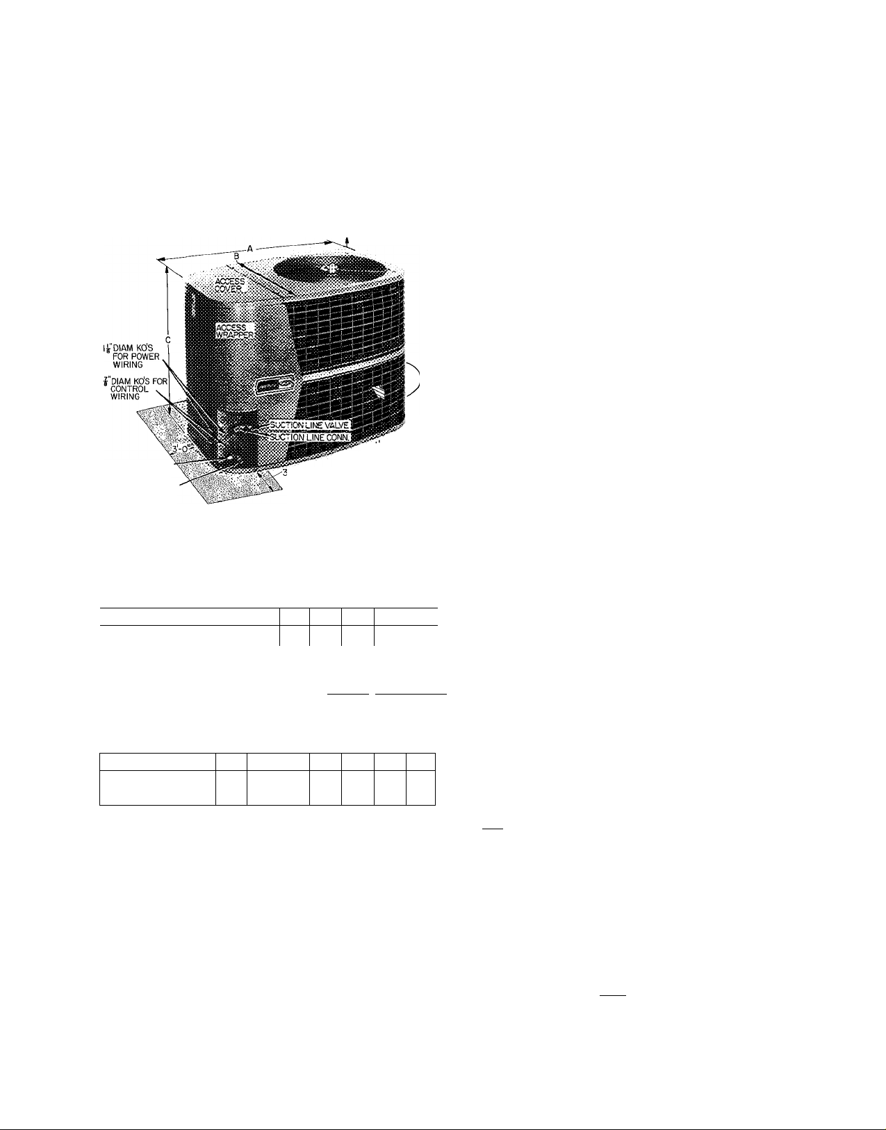
Heat Pump - Outdoor Section
4'0" OVERHEAD SPACE REQ'D
FOR SERVICE AND AIRFLOW
0 AIRFLOW
CLEARANCE
LIQUID LINE CONN
LIQUID LINE VALVE
Certified dimension drawings are available on request
i'-0"(B0TH SIDES)
ra SPACE REQ'D FOR SERVICE
^ AIRFLOW
(BOTH SIDES)
Fig. 1 — Dimensions and Connections (Table 1)
Table 1 — Installation Data (Fig. 1)
UNIT 38CQ
OPER WT (lb)
UNIT DIM. (ft-in.)
Length A
Width B
Height C
REFRIG CONN (in.)
Suction* (ODF)
Liquid* (ODF)
‘Recommended field supplied refrigerant line sizes
UNIT 38CQ 015
SUCTION (in. ODF)
LIQUID (in. ODF)
tMay use 7/8-in accy tubing package (slight capacity loss) See p 3
NOTES:
1 Maximum length of interconnecting tubing is 50 feet
2 Units 38CQ044, 048 factory supplied with 3/4 to 1-1/8 in suc
tion valve adapter (field installed) for field-supplied 1-1/8 in
suction line
; 015 1 Ò20
TÌ45 j_160
I -4^1 -4% 11 -4Vs[ 2-0)41 2-0yB|2-0VB 12-6Vs
Compatible Fitting (Suet) & Flare (Liq)
027
033
166 180
2-10V4
1-10
039
210
048
044
212 220
Ys I % I %
%
020 [027 033
5/
Vs 1 ^4
78
039
044t 048t
V
78
%
%
fZ 1
IVb
INSTALLER'S PRELIMINARY SURVEY
Step 1 — Unpackage Unit — Move heat pump to
final location. Open carton at end marked
“compressor end.” Slide unit from carton taking
special care to not damage service valves or grilles.
Step 2 — Inspect Equipment — File claim with
shipping company if shipment is damaged or
incomplete.
Step 3 — Complete or Consider the Following
before installing the 38CQ unit.
Consult local building codes and National
Electrical Code (NEC) for special installation
requirements.
When installing unit, allow sufficient space for
airflow clearance, wiring, refrigerant piping and
servicing unit. Position unit so water or ice from
roof will not drop directly on top of unit.
Make provisions for condensate drainage and
defrost water disposal whether unit is installed on
ground or roof. (Make sure unit base pan drainage
holes are not blocked.) See Mounting Pad for
details. Roof installation method for 38CQ
depends on building construction and special re
quirements of local codes. Roof must be capable of
supporting unit weight. Maximum allowable ver
tical distance between indoor and outdoor sections
is 50 feet. See Table 2.
Use an indoor coil with a bleed-type expansion
device. (See Table 2 for Carrier approved indoor
sections.) If coil does not have a bleed-type
expansion device, it may be necessary to add an
accessory start capacitor and relay to heat pump.
This would require removing compressor start
thermistor (PTC device) on units so equipped. It is
recommended that 38CQ units be used with
Carrier approved indoor sections, all of which are
equipped with a bypass type AccuRater'^^ (bleed-
type expansion device).
Table 2 — Carrier Approved 38CQ System Data
INDOOR UNIT
OUT
DOOR
UNIT
^ .38CQQ15
38CQ020
38CQ027
38CQ033
38CQ039
38CQ044
38CQ048
‘Indoor units that require replacement of AccuRater refrigerant
control piston for optimum performance when used with specified
outdoor unit The 38CQ048 is factory supplied with no 8 piston for
indoor unit (28MQ048)
REFRIG
ERANT
22
Fan
Coi
4gAQpi8
^^^40AQ024
40AQ024*
40AQ030
40AQ030*
40AQ036^_
40FSJI60|28MQ036
40AQ036*
40FS160
4ÒFSÌ60
40FS160
40FS200
40FS200
28MQ036'
'28MQ042
28MQ042*
28MQg48^
28MQ048''
AccuRafer
Piston
.
.. 6
. 6
.. .Tt...
j HEIGHT (ft)
; Above 1 Be low
II
2
4*
4 .
6*
. If .
7
8*
I
Indoor Unit
Outdoor Unit
50 50
(g) Carrier Corporation 1977
38CQ400105 B
Form 38CQ-6SI
Page 2
MOUIMTirJtTP^
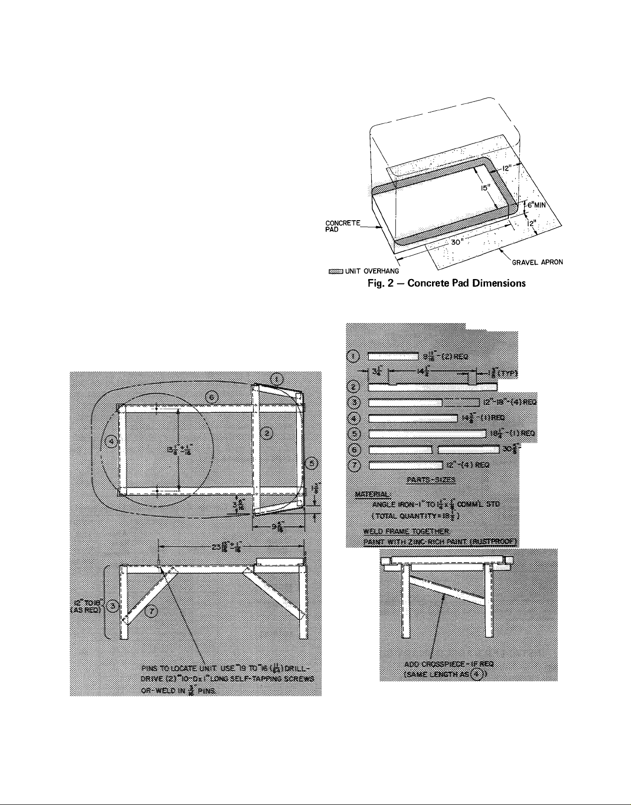
Step 4 — On the Ground: Mount Unit on a Solid,
Level Concrete Pad. See Fig. 2 for pad dimensions.
Position unit so that coil drainage holes in base pan
overhang the pad. Make sure pad does not obstruct
drainage holes (holes drain water during heating
and defrost cycles). Unit can be attached to pad
with mastic adhesive or by drilling holes in base
pan for 1/4-in. mounting bolts.
Construct pad a minimum of 6-in. thick to
provide clearance under holes for drainage and ice
buildup. In areas where prolonged subfreezing
temperature or heavy snows occur; increase clear
ance to 12 to 18 in. by constructing an angle iron
frame to support unit 12 to 18 in. off concrete
base. Cross angle of frame must not obstruct coil
drainage holes. See Fig. 3 for recommended frame
construction. Extend a 12-in. gravel apron around
pad for condensate and defrost water drainage
field.
Step 5 — On the Roof: Mount Unit on a Level
Platform or Frame: Unit must be elevated for
proper clearance as described under ground in
stallation above. Roof design and water drainage
must be planned to prevent unit from setting in
water. Flash all roof openings to prevent leaks.
«AtMtAK'tMV.VA'Kry.-
mtm
Fig. 3 — Heat Pump Mounting Frame
Page 3
PART NO.
38CQ900081
38C 0900111
38CQ900182
38GS900381
38CQ900061
38CQ900091
38RQ900001
38RQ900021
1hH22AG110
Low-Voltage Control — Honeywell Thermostat HH07AT071 and
Thermostat Subbase HH93AZ073 — (Automatic Changeover)
Low-Voltage Control — Honeywell Thermostat HH07AT071 and
Thermostat Subbase HH93AZ075 — (Manual Changeover)
Service Sentry (Six HN65CT002)
Start Capacitor and Relay Package
Flare (3/8-in.) to Compatible (3/8-in.) Couplings (Two-Pack)
Liquid Line Filter-Drier
Emergency Heat Relay (Required with 2 outdoor thermostats.)
(Service Parts)
Outdoor Thermostat (Six 38RQ900032)
Optimizer Control
38CQ900141 Solid State Time Guard (24 volt)
TUBING
PACKAGE
Length
(ft) OD 1 ube End
Liquid
(in.) OD (in.)
38GC900031
38GC900041
38GS900221
38GC900061 35
38GC900191
38GC900071 10
38GC900081
38GC900091 25
38GC900101 35
38GC900m
38CQ900001
38CQ9000n 25
38CQ900021 35
38CQ900031
*Suction line is insulated and has a 90 bend at one end
fFor 5/8-in evaporator connection, cut off 3/4-in end
10
18
25
% %
%
%
Ha
50
18
50
18
50
V4
V
V
4
V
4
V
4
V
4
4
V
4
V
4
___
Table 3 — Accessories
DESCRIPTION
TUBING
Va
Va
Va
Va
Va 4
4
V
4
Va
Va
V
4
Va
Va
Va
ICapacity reduction may occur when 7/8-in accessory tubing is used
on 38CQ044.048
____
Suction*
OD
(in.)
Va V4t Va
Va
Va V4t Va
Va V4Î Va
Va V4t
1 ube bnd
OD (in.)
Evap
V4t
V4
V4 V4
V4
V
4
V4
V
4
V4 V4
Vat
Vai
V
4
4
V4
Vai
V4
Cond
Va
V
4
y
4
y
4
y
4
y
4
y
4
y
4
4
V4
4
UNIT
38CQ015,020
38CQ027,033
38CQ039,044,048
PIPING CONNECTIONS
The 38CQ units can be connected to indoor
units using Carrier accessory tubing package or
field-supplied tubing of refrigerant grade. See
Table 1 (with notes) for unit piping connection
type, size and line size recommendations and
Table 3 for accessory tubing sizes. Maximum
length of refrigerant piping allowed is 50 feet
A capacity reduction will result if accessory
tubing is used in 38CQ044,048 systems. For
example, when a 25-ft, 7/8-in. accessory tubing
package is used, there will be a capacity reduction
of 1-1/2%. For maximum capacity, use 1-1/8 in.
suction line as recommended in Table 1.
When other than 25 ft of interconnecting
piping is used, follow special requirements de
scribed in Refrigerant Charging. Do not use less
than 10 ft of accessory liquid line. Do not cut
5/16-in. or 1/4-in. liquid line. Do not cut 7/8-in.
suction line. Bend or coil to fit.
Do not use damaged or contaminated tubing.
Always evacuate or purge evaporator coil and
tubing system (use field-supplied refrigerant, not
unit refrigerant).
When making tubing connections, be sure to
provide clearance at unit for electrical connections.
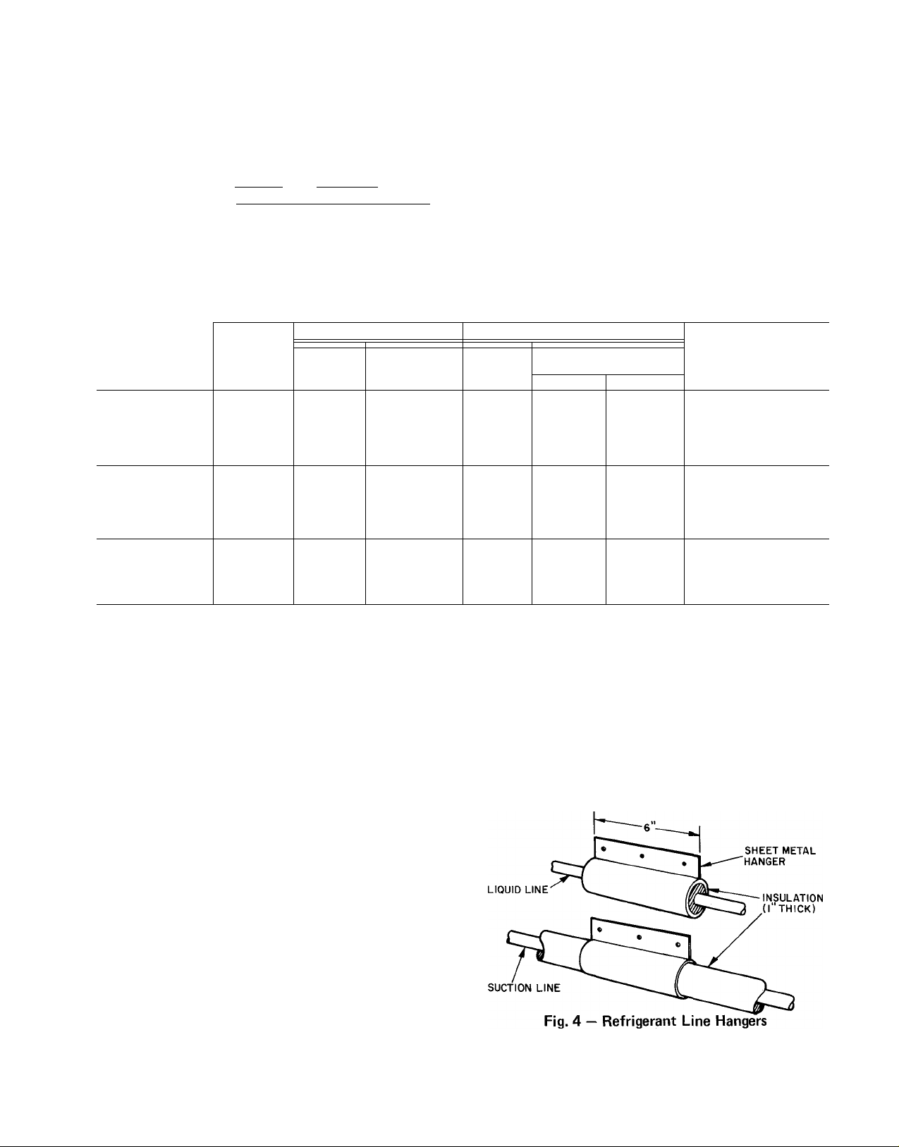
To assure noise-free installation, isolate refrig
erant lines from ductwork and framing or where
they run thru stud spaces, enclosed ceilings or pipe
chases. Use isolation hangers (Fig. 4), as rigid
fastening may transmit pulsations to structure,
creating an objectionable rumble. Do not attach
liquid line to uninsulated suction line. When
running thru structure, surround all lines with 1-in.
insulation to prevent transmission of vibration.
Before Connecting Refrigerant Lines, replace the
AccuRater'^'''^ refrigerant control piston in the
indoor coil as required. See Table 2. The 38CQ048 is
Page 4
factory supplied with a No. 8 AccuRater piston for
installation in 28MQ048. For piston replacement
instructions, see AccuRater’’"''^ Servicing on page 15.
Step 6 — Connect Refrigerant Lines to fittings on
unit suction and liquid service valves (Fig. 1).
Liquid service valve has flare fitting; suction service
valve has Compatible Fitting. Make suction line
connection first. Slide flare nut on liquid line, then
flare and connect liquid line. (Do not disassemble
AccuRater.) Unit Compatible Fitting permits
mechanical (quick-connect) or sweat connection as
described below. It is not necessary to flare system
liquid line if an accessory flare to Compatible
Fitting coupler is used for liquid line connection.
See Accessory Coupler (Fig. 5).
38CQ044,048 UNITS - When using 1-1/8 in.
field-supplied suction line, remove suction line
adapter taped to compressor suction line. Sweat
connect refrigerant suction line to 1-1/8 in. end of
adapter. Connect 3/4-in. end of adapter to unit
suction line Compatible Fitting.
When a 7/8-in. field-supplied suction line is
used on 38CQ039, a field-supplied 3/4-in. to
7/8-in. suction line adapter must be provided (not
required if 38CQ accessory tubing is used).
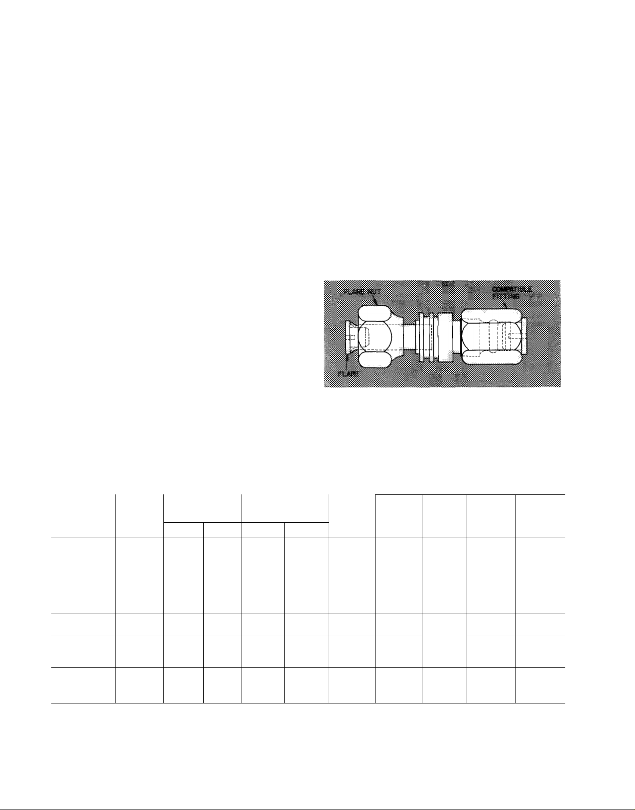
MECHANICAL CONNECTION TO COMPATIBLE
FITTING (Mate one set of connections at a time.)
1. Loosen nut on Compatible Fitting one turn. Do
not remove.
2. Remove plug and be sure 0-ring is in the groove
inside the Compatible Fitting.
3. Cut tubing to correct length.
4. Insert tube into Compatible Fitting until it
bottoms.
5. Tighten nut until it bottoms on back coupler
flange. Keep tube bottomed in Compatible
Fitting while tightening nut.
SWEAT CONNECTION TO
COMPATIBLE
FITTING (Use refrigerant tubing.)
Remove locking nut,
1.
rubber 0-ring and
Schrader core from valve.
2.
Cut tubing to correct length.
3.
Insert tube in Compatible Fitting. Wrap top and
bottom of service valves in wet cloth to prevent
damage by heat. Solder with low temperature
(450 F) silver alloy solder.
4.
Replace Schrader core.
5.
Evacuate or purge system with field-supplied
refrigerant.
ACCESSORY FLARE TO COMPATIBLE COU
PLER is shown in Fig. 5. Attach flare nut on
coupler to flare fitting on unit liquid service valve.
Connect liquid line to Compatible Fitting using
mechanical or sweat connection. When mechanical
connection is made, use 2 wrenches when tighten
ing Compatible Fitting nut — one to hold coupler
and one to tighten nut. Liquid line must be flared
if coupler is not used.
Fig. 5 — Accessory Coupler
ELECTRICAL DATA AND WIRING
Field wiring must comply with local and
national fire, safety and electrical codes. Voltage to
unit must be within ± 10% of voltage indicated on
Table 4 — Electrical Data (60-Hz)
OPER
UNIT V/PH
38CQ015 41
38CQ020 65 10.3
38CQ027 82
38CQ033
38CQ039
38CQ044
38CQ048 106
38CQ033
38CQ039
38CQ044
38CQ048
38CQ039
38CQ044
38CQ048
FLA — Full Load Amps
LRA — Locked Rotor Amps
RLA — Rated Load Amps
*Permissible limits of the voltage range at which the units will
operate satisfactorily
fRequired when using nonmetallic conduit
^Maximum dual element fuse size
230/1 254 207
200/
230/3
200/3
230/3
VOLTAGE*
Max Min
254 180 87
229 180 87 18.6
254
207 70
COMPR
LRA
88 19.8 2.4 10 36
94
106
79 17.4
87 18.6
67
70
BRANCH CIRCUIT
FAN
FLA
RLA
9.0
17.7 2.4 10 42
22.2
25.0
25.0
13.0/
11.5
15.0
16.7
16.7
.9 14 31
.9 12 40 12
2.4 10 33
2.4
3.0
2.0/
2.0
2.4 12 31
2.4 10 35
3.0 10 35
2.4 12
2.4 12
3.0 12
NOTES:
1 Fan motors are 200-v or 230-v, single phase
2 All units have 24-v control circuit which requires external
power source
3 Copper wire sizes based on 60 C Use copper or copper-clad
aluminum wire only Use latest National Electrical Code for
wire sizing
Power
Wire
Size
(AWG)
8 46
8
12
Max
Ft
Wire
46 8
40 12
41 12
36
36 12 35
Gnd
Wire
Sizef
(AWG)
14 20
10
10
10 50
8 50
12 40
10 40
10 40
12
Max
Fuse
Ampsi
20
40
45
50
30/
25
35
35
V
Page 5
f
THERMOSTAT
SUBBASE
HH93AZ073 OR
HH93AZ075
40AQ FAN COIL
COOLING CONTROL KIT
TERMINAL BOARD
38CQ
TERMINAL
BOARD
THERMOSTAT
SUBBASE
HH93AZ0730R
HH93AZ075
(38CX) WITH 40AQ OR 40FS/28MQ
EQUIPPED WITH ELECTRIC HEATER;
EMERGENCY HEAT, ONE OUTDOOR THERMOSTAT)
40AQ OR 40FQ
ELECTRIC HEATER
TERMINAL BOARD
38CQ
TERMINAL
BOARD
THERMOSTAT
SUBBASE
HH93AZ073 OR
HH93AZ075
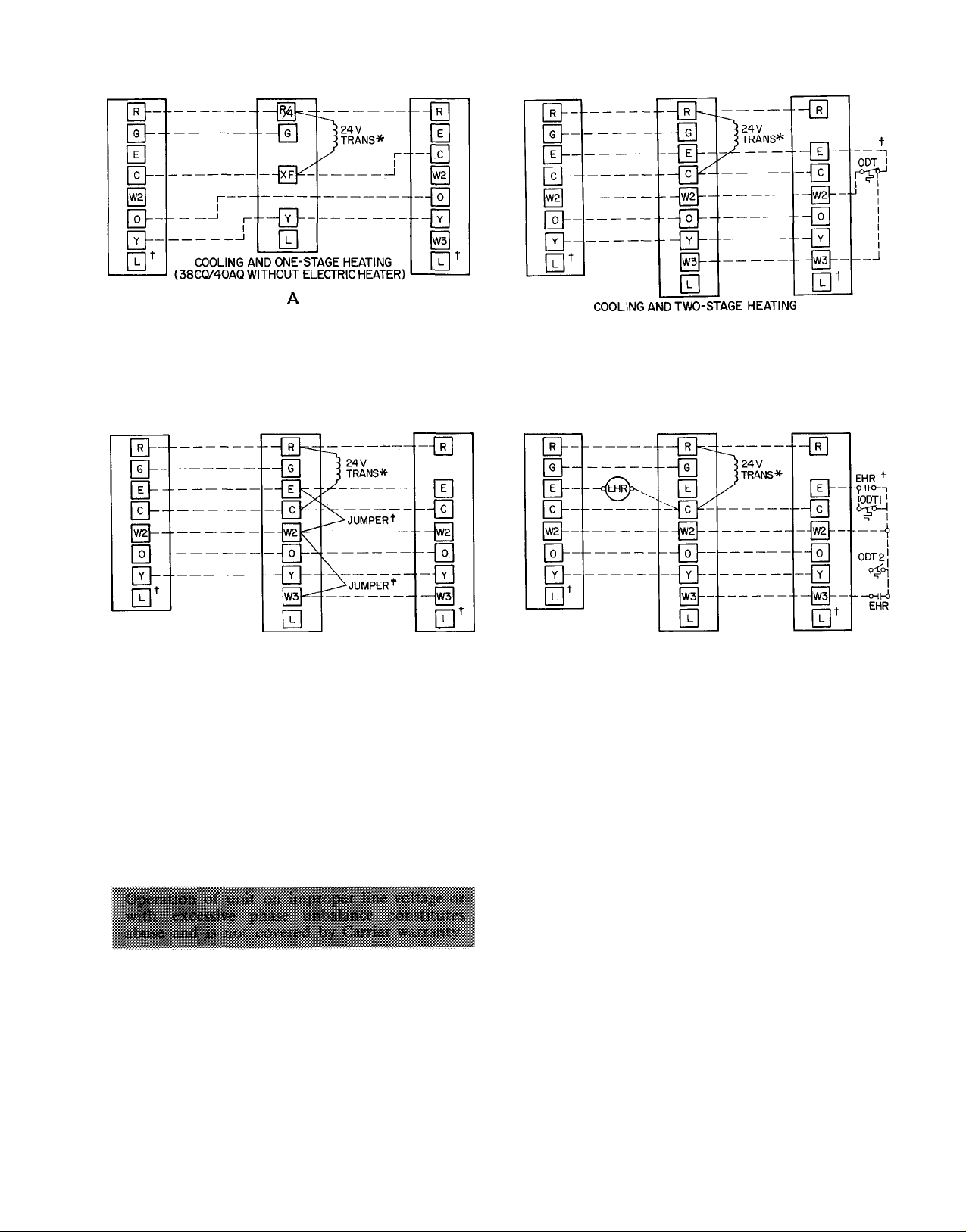
COOLING AND TWO-STAGE HEATING
(38CQ WITH 40AQ OR 40FS/28MQ
EMERGENCY HEAT, NO OUTDOOR THERMOSTATS)
EQUIPPED WITH ELECTRIC HEATER;
40AQ OR 40FQ
ELECTRIC HEATER
TERMINAL BOARD
B
EHR — Emergency Heat Relay
ODT — Outdoor Thermostat
_______
Factory Wiring
_______
Field Wiring
38CQ
TERMINAL
BOARD
THERMOSTAT
SUBBASE
HH93AZ073 OR
HH93AZ075
COOLING AND TWO-STAGE HEATING
EQUIPPED WITH ELECTRIC HEATER;
EMERGENCY HEAT, TWO OUTDOOR THERMOSTATS)
*Transformer (60 va) located in cooling control kit or electric heater
fTerminal L is identified as terminal X on some former thermostats
(Required for accessory Service Sentry)
:|;Remove factory-installed jumpers (connection B) when installing
outdoor thermostats (ODT)
Fig. 6 — Control Circuit Connections
40AQ OR 40FQ
ELECTRIC HEATER
TERMINAL BOARD
(38CQ WITH 40FS/28MQ
38CQ
TERMINAL
BOARD
nameplate. On 3'-phase units, phases must be
balanced within 2%. Contact local power company
for correction of improper line voltage.
When making electrical connections, provide
clearance at unit for refrigerant piping connections.
See Table 4 for recommended wire and fuse sizes.
Step 7 — Install a Branch Circuit Fused Disconnect
of adequate size to handle unit starting current.
Provide a separate fused disconnect for outdoor
unit, indoor unit and for each accessory electric
heater circuit as required. (See Indoor Unit and
Electric Heater Installation, Start-Up and Service
Instructions.) Locate disconnect(s) within sight of
and readily accessible from the unit, per section
440-14 of National Electrical Code (NEC).
Step 8 — Bring Line Power Leads Into Unit —
Extend leads from fused disconnect thru hole
provided in service embossment (Fig. 1) and thru
7/8-in. hole into control box.
Step 9 — Connect Ground Lead to a Ground Lug
in Control Box for safety. Connect power wiring.
See Fig. 7. Splice line power leads to yellow and
black pigtails on single-phase units or to black
pigtails (3) on 3-phase unit. Use wire nuts supplied
with unit. Tape each connection.
Step 10 — See Indoor Unit and Electric Heater
Installation, Start-Up and Service Instructions for
line power wiring details. All control wiring is
shown in this booklet.
Step 11 — Control Power Wiring (24 v) is brought
thru hole in unit service embossment. Fig. 1.
Connect leads to control wiring terminal board
(located on outside of control box) as shown in
Fig. 6.
Page 6
3-PHASE
CONN. TO
FUSED
DISCONNECT
I-PHASE
CONN. TO
FUSED
DISCONNECT
_________
L
------------
BLK-
GROUND LUG
38CQ HEAT PUMP
CONTROL BOX
Fig. 7 — Line Power Connections
BLK-
YEL OR BLK
------
emergency heat switch in the indoor thermostat
subbase. The thermostat locks out compressor and
the relay bypasses the outdoor thermostats for
electric heater operation during heat pump shut
down. When one outdoor thermostat is used, an
emergency heat relay is not required. The emer
gency heat switch in the indoor thermostat subbase
bypasses outdoor thermostat, locks out compressor
and activates electric heater. See 40FS Indoor Unit
and Electric Heater Installation, Start-Up and
Service Instructions for installation of emergency
heat relay.
Use indoor unit transformer as 24-v supply for
system. At least a 60-va transformer is recom
mended. Carrier approved indoor units are
equipped with 60-va transformer. See indoor unit
data.
Use Carrier accessory indoor thermostat
HH07AT071 with HH93AZ073 or HH93AZ075
subbase.
IWITIAL START-UP
The 38CQ unit is equipped with a crankcase
heater. It is recommended that heater be energized
a minimum of 24 hours before starting unit. To
energize heater only, turn the thermostat to OFF
position and close electrical disconnect to heat
pump.
Heat Anticipator Settings for Room Thermostat
(HH07AT071) — Set anticipator settings for room
thermostat according to Table 5. These settings
may be changed slightly to provide a greater degree
of comfort for a particular installation.
Table 5 — Thermostat Anticipator Settings
UNIT
38CQ
015
020
027
033
039
044
048
FIRST-
STAGE
ANTICIPATOR
SETTING
Fixed
INDOOR
UNIT WITH
ELECTRIC
HEATER
40AQ Fan-Coil
with 40AQ Htrs
40FS/28MQ
with 40FQ
Htrs
HTR
KW
5 0
7 5
10 0
15 0
20 0
25 0
30 0
34 0
second-
stage
ANTICIPATOR
SETTINGS
16
33
49
Accessory Outdoor Thermostat provides adjustable
outdoor control of accessory electric heater. This
thermostat makes contact when a drop in outdoor
temperature occurs. It energizes a stage of electric
heat when the outdoor temperature setting is
reached, provided the room thermostat is on the
second stage of heating. One outdoor thermostat is
recommended for each stage of electric heat after
the first stage. Set the outdoor thermostat(s)
progressively lower for each stage. Refer to heat
load of building and unit capacity to determine the
correct outdoor thermostat settings.
The accessory emergency heat relay is required
when 2 outdoor thermostats are used. It is auto
matically energized by the manually operated
Accessory Outdoor Thermostat(s) Installation —
Install outdoor thermostat at a suitable location on
the outside of the control box. Use any free hole
to fasten thermostat bracket. Be sure that engage
ment screw does not interfere with wiring or
components inside of control box Thermostat
bracket may be secured with only one screw;
however, make sure that bracket is firmly attached
to resist vibration forces. If a free hole is not
available, drill hole in control box after assuring
that drilling will not damage any components
inside of box If a second thermostat is used,
follow the procedure outlined above. If there is no
available space on the control box for a second
thermostat, mount the 2 thermostats together.
Connect the 2 thermostats with a machine screw,
lock washer and nut, and then mount assembled
thermostats to the control box (See Fig. 8a).
Route the capillary and attached bulb below the
control box to the upper portion of the outdoor
coil grille. Carefully insert the bulb between the
tube sheet and nearest vertical grille wire. Place the
bulb across the grille and fasten with wire, wire ties
or other suitable fastener (See Fig. 8b). Never
expose bulb to direct sunlight. If necessary, shield
bulb with appropriate material.
Replace access wrapper on unit. Check that
capillary is not pinched by wrapper
To Start Unit — (Make sure crankcase heater has
been energized for 24 hours.) Adjust the thermo
stat as follows:
1. Set selector switch at OFF.
2. Turn on main disconnect switch(es) to indoor
and outdoor units.
3. Set fan switch as desired (ON or AUTO.).
4. Set thermostat dial at desired temperature.
5. Set selector switch at HEAT or COOL.
Check system refrigerant charge. See Refrig
erant Charging.
SERVICE
Refrigerant Charging — The 38CQ units contain
correct operating charge for complete system when
connected to 40FS/28MQ or 40AQ indoor units
with 25 ft of tubing of recommended diameter.
Charge adjustment is required on other systems.
Adjust system charge for refrigerant line lengths
and diameters that differ from 25 ft and 3/8-in.
V
Page 7

OD (liquid line), respectively, using refrigerant
weights shown in table below. (Twenty-five feet of
3/8-in. OD tubing contains 14.4 oz of R-22.) Add
R-22 charge to system if liquid line is over 25 ft;
remove charge if liquid line is shorter than 25 feet.
(
LIQUID LINE 1 OUNCES OF ^22/FT LENGTH
DIAM (in.) OF LIQUID LINE
3/8
5/16
1/4
58
36
21
Table 6 — Service Data
UNIT 38CQ
R-22 CHG
(Ib-oz) 1 4-10 4-1 1 6-5 7-11 7-13 7-10
REFRIG CONTROL A ccuRater*^^
FAN 1 Prope
Cfm
Rpm
Diam (in.) 1 17
Motor Hp
1 015,
1 020
]
1
2600
1/8
2600
027 033 039
(Bypass Type
Her - Direct Drive
2800
1075
17 18 18 16 18
1/4 1/4 1/4
1/4
044
2800 1 2600 3400
048
)
1/2
system before recharging. If system has lost com
plete charge, evacuate system to 500 microns (29.7
in. vacuum) before recharging. Service port connec
tions are provided on liquid and suction line service
valves for evacuation and charging. (See Fig. 32 for
correct service port location on cooling and heating
cycles.) DiaTa-charge charging cylinder is an
accurate device used to recharge systems by
weight. These cylinders are available at refrig
eration supply firms.
To check and/or adjust charge during cooling
season, use correct Cooling Cycle Charging Chart
(Fig. 9, 11, 13, 15, 17, 19, 21,23, 25, 27, 29) and
follow Charging Chart Method below. The charging
chart may also be used as an alternate method of
recharging system.
To check system operation during heating
cycle, use correct Heating Cycle Operation Check
Chart (Fig. 10, 12, 14, 16, 18, 20, 22, 24, 26,28,
30). These charts indicate whether a correct
relationship exists between system operating pres
sures and air temperatures entering indoor and
outdoor units. If pressure and temperature lines do
not intersect on chart, the system refrigerant
When recharging is necessary during heating or
cooling season, weigh in total charge indicated in
Table 6. (Charge must be weighed in during heating
season.) Remove any refrigerant remaining in
charge may not be correct or other system abnor
malities may exist. Do not use Operation Check
Charts to adjust refrigerant charge. Weigh charge
into system.
a. 2 — Thermostat Assembly b. Capillary Tube Routing
^ Fig. 8 — Outdoor Thermostat Installation Details
7
Page 8

COOLING CYCLE CHARGING CHART
METHOD
1. Operate unit a minimum of 10 minutes before
checking charge, and after each charge
adjustment.
2. Measure suction pressure by attaching a gage to
outdoor unit suction valve service port. (See
Fig. 32 for correct service port location on
cooling cycle.)
3. Measure outdoor (coil inlet) air dry-bulb tem
perature with service thermometer.
4. Using a sling psychrometer, measure wet-bulb
temperature of air entering indoor unit.
5. Refer to correct Charging Chart. Locate on
curves where outdoor air dry-bulb and indoor
air wet-bulb temperature lines intersect.
6. From intersect point, project vertically down
ward to chart suction pressure line. Compare
chart suction pressure to unit suction pressure
(Step 2).
7. If unit suction pressure is lower than chart
pressure, add refrigerant to system until chart
pressure is reached. If unit suction pressure is
higher than chart pressure, remove refrigerant
until chart pressure is reached.
340
320
300
3
5
ui
£ 280
o 260
PRESSURE AT SUCTION SERVICE VALVE (PSIG)
Fig. 9 — 38CQ015 with 40AQ018 Cooling Cycle
Charging Chart (R-22)
cr 240
220
20 O'
66 68 70 72 74 76 78 80 82 84 86 88 90
PRESSURE AT SUCTION SERVICE VALVE (PSIG)
Fig. 11 — 38CQ020 with 40AQ024 Cooling Cycle
Charging Chart (R-22)
Fig. 10 — 38CQ015 with 40AQ018 Heating Cycle
Operation Check Chart (R-22)
Fig. 12 — 38CQ020 with 40AQ024 Heating Cycle
Operation Check Chart (R-22)
Page 9

PRESSURE AT SUCTION SERVICE VALVE (PSI6)
Fig. 13 — 38CQ027 with 40AQ024 Cooling Cycle
Charging Chart (R-22)
Fig. 15 — 38CCX)27 with 40AQ030 Cooling Cycle
Charging Chart (R-22)
Fig. 14 — 38CQ027 with 40AQ024 Heating Cycle
Operation Check Chart (R-22)
Fig. 16 — 38CQ027 with 40AQ030 Heating Cycle
Operation Check Chart (R-22)
Page 10

360
Fig. 17 — 38CQ033 with 40AQ030 Cooling Cycle
Charging Chart (R-22)
260-
240-
DRY-BULB TEMP AIR
ENT OUTDOOR UNIT
(F)
WET-BULB TEMP AIR
ENT INDOORUNIT(f:
i8^
340
S» 320
£
^ 300-
o
280
o
220
200
66 68 70 72 74 76 78 80 82 84 86 88 90
PRESSURE AT SUCTION SERVICE VALVE (PSIG)
Fig. 19 - 38CQ033 with 40FS160/28MQ036 or
40AQ036 Cooling Cycle Charging Chart (R-22)
Fig. 18 — 38CQ033 with 40AQ030 Heating Cycle
Operation Check Chart (R-22)
Fig. 20 - 38CQ033 with
40FS160/28MQ036 or 40AQ036
Heating Cycle Operation Check Chart (R-22)
10
Page 11

PRESSURE AT SUCTION SERVICE VALVE (PSIG)
Fig. 21 - 38CQ039 with 40AQ036 or 40FS160/
28MQ036 Cooling Cycle Charging Chart (R-22)
Fig. 23 - 38CQ039 with 40FS160/28MQ042
Cooling Cycle Charging Chart (R-22)
SUCTION PRESSURE AT SERVICE PORT(PSIG)
Fig. 22 - 38CQ039 with 40AQ036 or 40FS160/
28MQ036 Heating Cycle Operation Check Chart
Fig. 24 - 38CQ039 with 40FS160/28MQ042
Heating Cycle Operation Check Chart (R-22)
11
Page 12

PRESSURE AT SUCTION SERVICE VALVE (PSI6)
Fig. 25 - 38CQ044 with 40FS160/28MQ042
Cooling Cycle Charging Chart (R-22)
PRESSURE AT SUCTION SERVICE VALVE (PSIG)
Fig. 27 - 38CQ044 with 40FS200/28MQ048
Cooling Cycle Charging Chart (R-22)
SUCTION PRESSURE AT SERVICE PORT(PSIG)
Fig. 26 - 38CQ044 with 40FS160/28MQ042
Heating Cycle Operation Check Chart (R-22)
Fig. 28 - 38CQ044 with 40FS200/28MQ048
Heating Cycle Operation Check Chart (R-22)
12
Page 13

300
Fig. 29 - 38CQ048 with 40FS200/28MQ048
Cooling Cycle Charging Chart (R-22)
280
260
>240
fE 220
£ 180
140
120
WET-BULB TEMP
AIR ENT
OUTDOOR UNIT{F)
23.5F
15 F
9F
M
-I0.5F
20 30 40 50 60
SUCTION PRESSURE AT SUCTION SERVICE PORT
43F
I
33F
Fig. 30 - 38CQ048 with 40FS200/28MQ048
Heating Cycle Operation Check Chart (R-22)
DRY-BULB TEMP
AIR ENT
INDOOR UNIT (F)
70
Unit Single-Phase Compressors
COMPRESSORS OF THE SPLIT CAPACITOR
(PSC) TYPE require an equalized system pressure
to start. When supply voltage is within 10% limit
and compressor does not start, give compressor a
temporary capacitance boost. See Carrier Standard
Service Techniques Manual, Chapter 2, for details.
Use a 130-mfd start capacitor. Connect wires with
insulated probes to each capacitor terminal. Touch
probes to each side of run capacitor or to
compressor motor terminals R and S. Start com
pressor; pull probes away after 3 seconds Dis
charge start capacitor. Run compressor for 10
minutes, then shut off and allow system pressure
to equalize. Try restarting without boost capacitor.
If after 2 attempts (without boost capacitor) the
compressor does not start, add an accessory start
thermistor (PTC device). If after 2 more attempts
the compressor does not start, remove thermistor
and add an accessory start capacitor relay package.
COMPRESSORS THAT ARE EQUIPPED WITH A
COMPRESSOR START THERMISTOR (PTC
device): if compressor does not start, check the
thermistor with an ohmmeter as described below.
Earlier unit models have a 50-ohm thermistor (with
2-prong connections), later models have a 25-ohm
thermistor (with 3-prong connections). If indoor
coil does not have a bleed-type expansion device, it
may be necessary to remove start thermistor and
replace with accessory start capacitor and relay.
Checking Start Thermistor
1. Shut off all power to unit and wait 5 minutes
for thermistor to cool to outdoor temperature.
2. Measure resistance of thermistor with ohmmeter. Normal resistance readings at 75 F out
door temperature are: 50 to 90 ohms for
50 ohm thermistor; 25 to 50 ohms for 25 ohm
thermistor.
3. If ohmmeter resistance reading is 0 or much
higher than 50 or 90 ohms, the thermistor is
defective and must be replaced.
If start thermistor is good and compressor does
not start, disconnect the thermistor from starting
circuit and give compressor a temporary capaci
tance boost as described above. Run compressor
for 10 minutes, then shut off and allow system
pressure to equalize. Reconnect start thermistor
and try restarting compressor without boost capa
citor. If aher 2 attempts the compressor does not
start, remove thermistor and add an accessory start
capacitor relay package.
13
Page 14

Compressor Removal — See Table 7 for compressor
information and Fig. 31 for component location.
Follow safety codes, and wear safety glasses and
work gloves. Have quenching cloth available
(Step 7).
pressor hold-down bolts are in place. Connect
wiring.
11. Evacuate and recharge unit.
FILTER-DRIER — Install accessory heat pump
filter-drier (Table 3) in system liquid line when
refrigerant system is opened for service as de
scribed under Compressor Removal. Position drier
in liquid line at convenient location. Do not use a
standard single-pass filter-drier.
1. Shut off power to unit. Remove unit top
access cover and rear access wrapper.
2. Remove refrigerant from unit using refrigerant
removal methods described in Carrier Standard
Service Techniques Manual, Chapter 1.
3. Disconnect compressor wiring at compressor
terminal box.
4. Using a tubing cutter, cut suction and dis
charge lines at convenient place near com
pressor for easy reassembly to new compressor
with copper slip couplings.
5. Remove crankcase heater from compressor
base.
6. Remove compressor hold-down bolts and lift
compressor out.
7. Carefully unbraze suction and discharge line
piping stubs from compressor. If oil vapor in
piping stubs ignites, use quenching cloth.
8. Braze piping stubs (removed in step 7) on new
compressor.
9. Clean system. Add new liquid line heat pump
filter-drier as described below.
10. Install new compressor in unit. Braze suction
and discharge lines to compressor piping stubs
(at points where cut, step 4) using field-
supplied copper couplings. Make sure com
Table 7 — Compressor Data
UNIT
38CQ015
38CQ020
38CQ027
38CQ033
38CQ039
38CQ044
38CQ048
38CQ039
38CQ044
38CQ048
38CQ039
38CQ044
38CQ048
‘Refer to Service Parts catalog for replacement compressor
model numbers
V/PH
230/1
200/3
230/3 PG5316HD
PRODUCTION —
Model*
38CQ400994
MD2023HB
MD3023HB
MC3423HB
PC4Ó16HD
PC5316HD
PC5316HD
PF4616HD
PF5316HD
PF5316HD
.
PG4616HD
PG5316HD
Oil Recharge (oz)
20
44
44
44
64
64
64
64
64
64
64
64
64
Pumpdown Procedure (Cooling Cycle) — The
38CQ units may be pumped down in order to
make repairs on low side of system without losing
complete refrigerant charge. Ensure unit is in
cooling mode.
1. Attach pressure gage to suction service valve
service port.
2. Frontseat the liquid line valve.
3. Start unit and run until suction pressure reaches
5 psig (see Caution).
4. Shut unit off and frontseat suction valve.
5. Vent remaining pressure to atmosphere.
FAN COMPARTMENT
-WAY VALVE
CONTROL BOX
DISCHARGE LINE
MUFFLER
(039,044,048)
COMPRESSOR
Fig. 31 — Component Location
14
CONTROL WIRING
TERMINAL BOARD
ACCUMULATOR'
SUCTION LINE
SERVICE VALVE-
LIQUID LINE
SERVICE VALVE
Page 15

Unit Controls and Safety Devices
HIGH-PRESSURE RELIEF VALVE is located in
compressor. Relief valve opens at a pressure differ
ential of approximately 600 psi between suction
(low side) and discharge (high side) to allow
pressure equalization.
INTERNAL CURRENT AND TEMPERATURE
SENSITIVE OVERLOAD resets automatically
when internal compressor motor temperature
drops to a safe level (overloads may require up to
45 minutes to reset). When an internal overload is
suspected of being open, check by using an
ohmmeter or continuity tester. If necessary, refer
to Carrier Standard Service Techniques Manual,
Chapter 2, for complete instructions.
LIQUID LINE LOW-PRESSURE SWITCH (LLPS)
is connected in liquid line to work with compressor
internal thermostat in providing loss-of-charge pro
tection during the heating cycle. Control is
mounted on liquid line.
With a high-side leak, pressure gradually de
creases until low-pressure control stops the com
pressor. (Low-pressure control settings are shown
in Table 8.)
Table 8 — Pressure Switch Settings
UNIT
38CQ
015
020
027
033 20 + 5 5+3
039
044
048
Cut-in (psig) Cutout (psig)
LIQUID LINE
LOW-PRESSURE SWITCH
With a low-side leak there is always some
pressure in the liquid line. However, compressor
motor temperature increases because of in
sufficient suction gas cooling. This causes internal
thermostat to actuate and stop compressor. When
compressor stops, system pressure equalizes and
contacts on pressure control open. The compressor
cannot restart until leak is repaired and system
recharged.
CRANKCASE HEATER is connected across line
side of contactor and operates continuously.
The purpose of the heater is to keep the
crankcase warm during the off cycle and thus
prevent dilution of the oil with refrigerant. This
assures good lubrication and prevents loss of oil
from crankcase during start-up.
If the electrical disconnect switch to the out
side unit has been off for an extended period of
time, the crankcase heater should be energized for
24 hours before starting the compressor
DEFROST CONTROL, consisting of a defrost
timer, defrost thermostat and defrost relay, inter
rupts normal system heating operation every 90
minutes to defrost outdoor coil, if the coil satu
rated suction temperature indicates freezing
temperatures. Defrost control simultaneously stops
outdoor fan, energizes reversing valve solenoid to
return system to cooling cycle (outdoor unit as
condenser, indoor unit as evaporator), and acti
vates accessory electric heater.
For the heat pump to defrost, 2 conditions are
necessary:
1. Defrost timer contacts must be closed.
2. Refrigerant temperature from outdoor unit
must be cold enough to cause defrost ther
mostat contacts to close. Contacts close at 31
(±4) F.
Every 90 minutes of elapsed running time, the
defrost timer contacts close for 10 seconds. If the
defrost thermostat contacts are closed, the unit
defrosts. The defrost timer limits defrosting period
to 10 minutes. Normally the frost is removed and
the defrost thermostat contacts will open to
terminate defrosting before 10 minutes have
elapsed. Defrost thermostat contacts open at 80
(±6) F liquid refrigerant temperature. When de
frosting is terminated, the outdoor fan motor is
energized and reversing valve solenoid is de
energized returning unit to heating cycle.
HEAT PUMP CIRCUITS shown in Fig. 32 are
refrigerant flow diagrams for heating and cooling
cycles.
AccuRater^''^ (Bypass Type) Servicing — See Fig.
33 for bypass type AccuRater components. The
piston has a refrigerant metering hole thru it. The
retainer forms a stop for the piston in the
refrigerant bypass mode, and a sealing surface for
liquid line flare connection. To check, clean or
replace piston:
1. Shut off power to unit.
2. Pump unit down using Pumpdown Procedure
described previously.
3. Remove liquid line flare connection from
AccuRater.
4. Pull retainer out of body being careful not to
scratch flare sealing surface. If retainer does not
pull out easily, carefully use vise grips or pliers
to remove retainer.
5. Slide piston out by inserting a small soft wire,
with small kinks, thru metering hole. Ensure
metering hole, sealing surface around piston
cones and fluted portion of piston are not
damaged.
15
Page 16

SUCTION
SERVICE
PORTAT
SERVICE
VALVE
(HTG CYCLE)
OUTDOOR
COIL
SUCTION
SERVICE
PORT
ACCESSORY
FILTER DRIER
DISCHARGE
SERVICE
PORT AT
SERVICE
VALVE
(HTG CYCLE)
LIQUID LINE
SERVICE
PORT AT
SERVICE
VALVE
(CL6 CYCLE)
ACCESSORY
FILTER DRIER
BYPASS TYPE
ACCURATOR (PERMITS FLOW
IN EITHER DIRECTION)
STRAINERS
ACCUMULATOR
-WAY valve
SUCTION
SERV^ICE
PORTAT
SERVICE
VALVE
(CLG CYCLE)
iUNIT PIPING
HEATING CYCLE
Fig. 32 — 38CQ Refrigerant Flow Diagrams
Fig. 33 — AccuRater^'^ (Bypass Type) Components
6. Clean piston refrigerant metering hole.
7. Replace retainer 0-ring before reassembling
bypass type AccuRater. Carrier O-ring part no.
is99CC501052.
LIQUID LINE STRAINER (protects AccuRater)
made of wire mesh is located in the liquid line
inside 38CQ unit behind liquid line service valve.
Liquid line is belled and sweat connected where
strainer is located. If strainer is plugged, unsweat
belled liquid line connection and replace strainer.
Compatible Fitting Repair
LEAKING MECHANICAL CONNECTION Frontseat outdoor section service valves and relieve
refrigerant pressure in tubing. Back locknut off
Carrier Compatible Fitting onto tube. Cut fitting
between threads and seal ring bead shown in
Fig. 34. Remove tubing section remaining in
threaded portion of fitting. Discard locknut.
Clean, flux, and insert new tube end into
remaining portion of Carrier Compatible Fitting.
Wrap valve base in wet rag. Heat and apply
low-temperature solder (450 F).
COOLING CYCLE
LEAKING SWEAT CONNECTION - Frontseat
service valves and relieve refrigerant pressure in
tubing. Clean and flux area around leak and apply
low-temperature solder (450 F).
Evacuate or purge indoor coil and tubing
system. Add refrigerant charge (seb charging
instructions).
Leaking Flare Connection — Cut and reflare 3/8-in.
system liquid line.
I,
Fig. 34 — Carrier Compatible Fitting
16
Page 17

Outdoor Fan Position — Required fan position is
shown in Fig. 35. Adjust fan by loosening setscrew
and moving fan blades up or down.
Fan Motor Removal
1. Shut off power to unit.
2. Remove unit top access cover and fan grille.
3. Disconnect fan motor wires from fan capacitor
and control relay or contactor. Pull wires out of
control box.
4. Remove fan from motor shaft by loosening
setscrew and pulling upward on fan hub.
5. Remove rain shield from motor shaft by pulling
upward.
6. Loosen bolt holding fan motor to motor
mounting bracket. Remove motor thru top of
unit. To replace motor, place motor on self
positioning motor mounting flanges and re
tighten bolt.
Before replacing fan, ensure rain protector is in
place on motor shaft.
FAN BLADE
MOTOR
setscrew""
Fig. 35 — Condenser Fan Position
MAINTENANCE
Outdoor Coil Cleaning — Inspect coil periodically.
Clean coil with water at the beginning of every
cooling season or more often if required. Use
ordinary garden hose at a pressure high enough to
clean efficiently. For best results, unscrew and
remove unit top cover (grille). Insert hose nozzle
between fan blades and spray coil fins from
inside-to-outside the unit or top to bottom be
tween rows of tubing. If unit has a double-row coil,
loosen screws to separate coils. Pull outer row of
coils away from inner row and flush dirt toward
outside of both coils. Flush dirt from base pan by
spraying water thru top of unit. Avoid splashing
mud on coil or water on fan motor. Make sure
water drainage holes under outdoor coil are not
obstructed.
Lubrication
FAN MOTOR BEARINGS - Oiling holes are
provided at each end of outdoor unit fan motor.
Remove fan motor and lubricate motor with 32
drops (16 drops per hole) of SAE-10 nondetergent
oil at intervals described below:
a. Annually, when environment is very dirty,
ambient temperature is higher than 105 E and
average unit operating time exceeds 15 hours a
day.
b. Every 3 years when environment is reasonably
clean, ambient temperature is less than 105 F
and unit operating time averages 8 to 15 hours
a day.
c. Every 5 years when environment is clean,
ambient temperature is less than 105 F and unit
operating time averages less than 8 hours a day.
COMPRESSOR contains factory oil charge. When
oil is lost, see Table 7 for oil charge and Carrier
Standard Service Techniques Manual, Chapter 1,
page 1-21, for instructions. Use Carrier PP33-1,
Texaco Capella B or Suniso 3G oil.
17
Page 18

00
TROUBLESHOOTING CHART - COOLING CYCLE
Page 19

TROUBLESHOOTING CHART - HEATING CYCLE
Page 20

SI METRIC CONVERSIONS
(°F - 32) X 5/9
= °C
BTU X 1.055 = kJ
BTU/hr X
Tons refrig x 3.517
0.2931 = W
= kW
HP X 0.7457 = kW
kcal/hr X
ft X
1.163
0.3048
ft^x 0.09290
fpm
in X
0.005080
25.4 = mm
in wg 39.2° F x 0.2491
in Hg 32° F X 3.386
CFM X
gpm (U.S.) X
0.0004719
0.06309 = l/s
Ibx 0.4536
lb/in^ X 6.895
OZ. X 0.02835
fluid OZ. (U.S.) X 0.02957 = 1
kcal X
kg f/cm^ X
Metric HP X
4.1855
98.07 = kPa
735.5 = W
pints X 0.4732
= W
= m
= m2
= m/s
= kPa
= kPa
= m^/s
= kg
= kP
= kg
= kJ
= 1
For replacement items use Carrier Specified Parts.
Manufacturer reserves the right to discontinue, or change at any time, specifications or designs without notice and without incurring obligations.
Tab 12 Form 38CQ-6SI Supersedes 38CQ-4SI Printed in USA 1-77 PC 101 Catalog No 533-854
Book
1 4
Tab 5a
5a
 Loading...