

Carrier 38CKPC36DS70, 38CKPS42DS90, 38CKPC36DS90, 38CKPC18DS70, 38CKPS48DS90 Installation, Operation And Maintenance Manual
...Page 1
Installation, Operation and Maintenance Manual
38C – 50Hz
Nominal Cooling Capacity 1.5 – 5.0 Tons
HFC R -410A Refrigerant
38C Top Discharge Condensing Units – 50Hz
Quality Assurance
04 100 950420
Page 1
Certificate Reg. No:
Subject to change without notice
Manufacturer’s Name: Saudi Airconditioning Manufacturing Co. Ltd.
Country of origin : Jeddah, Saudi Arabia
Nearest port of embarkation: Jeddah Islamic port
Product classification: Commercial and Residential
The 38C series energy efficient split top discharge condensing units incorporate innovative technology to provide
reliable summer cooling performance. The units are pre-wired, pre-charged with Puron® R-410A refrigerant, and
tested at the factory, designed to occupy a minimal space. These units are matched with Carrier direct expansion fan
coil units that provides economical performance now and in the future.
Contact your local Carrier representative for additional support.
Page 2

Table of Contents
Page 2
Safety Considerations ................................................................................................................................................... 2
Physical Data ................................................................................................................................................................ 3
Base Unit Dimensions .................................................................................................................................................. 4
Combination Matrix and Ratings / Electrical Data ........................................................................................................ 5
Typical Wiring Schematic ............................................................................................................................................. 6
Installation / Startup / Service / Maintenance .............................................................................................................. 8
Superheat Charging Table / Required Suction Tube Temperature ............................................................................ 16
Pressure vs. Temperature Chart R-410A ................................................................................................................... 17
Required Liquid Line Temperature ............................................................................................................................. 18
R-410A Refrigerant Quick Reference Guide .............................................................................................................. 19
Air Conditioner Troubleshooting Chart ....................................................................................................................... 20
Mandatory Startup Checklist and Record ................................................................................................................... 21
Long Line Guideline .................................................................................................................................................... 23
1 – SAFETY CONSIDERATIONS
1.1 – General
Improper installation, adjustment, alteration, service, maintenance or use can cause explosion, fire, electrical shock
or other conditions which may cause personal injury or property damage. Consult a qualified installer; service
agency must use factory-authorized kits or accessories when modifying this product. Refer to the individual
instructions packaged with the kits or accessories when installing.
The appliance is not to be used by persons (including children) with reduced physical, sensory or mental
capabilities, or lack of experience and knowledge, unless they have been given supervision or instruction. Children
should be supervised not to play with the appliance.
Follow all the safety codes. Wear safety glasses and work gloves. Use quenching cloths for brazing operations and
have a fire extinguisher available. Read these instructions thoroughly and follow all warnings or cautions attached
to the unit. Consult local building codes for special requirements. In absence of local codes, it is recommended that
the USA standard ANSI/NFPA 70, National Electrical Code (NEC), be followed.
It is important to recognize safety information. This is the safety-alert symbol . When you see this symbol on
the unit and in instructions or manuals, be alert to the potential for personal injury.Understand the signal words
DANGER, WARNING, CAUTION, and NOTE. These words are used with the safety-alert symbol. DANGER
identifies the most serious hazards which will result in severe personal injury of death. WARNING signifies hazards
which could result in personal injury or death. CAUTION is used to identify unsafe practices, which may result in
minor personal injury or product and property damage. NOTE is used to highlight suggestions which will result in
enhanced installation, reliability, or operation.
1.2 – Installation Safety Considerations
After the unit has been received and when it is ready to be installed or reinstalled, it must be inspected for damage.
If damage is detected upon receipt, immediately file a claim with the shipping company or repair. This machine
must be installed in a location that is not accessible to the public and protected against access by non-authorized
people. This machine must not be installed in an explosive atmosphere.
Do not remove the skid or the packaging until the unit is in its final position. The units can also be lifted with slings,
using only the designated lifting points marked on the unit (labels on the chassis and a label with all unit handling
instructions are attached to the unit). Use slings with the correct capacity, and always follow the lifting instructions
on the certified drawings supplied for the unit.
Safety is only guaranteed, if these instructions are carefully followed. If this is not the case, there is a risk of
material deterioration and injuries to personnel. These units are not designed to be lifted from above.
1.3 – Warranty
Warranty is based on the general terms and conditions of the manufacturer. Any modifications to the design and/or
installation made without discussion with Carrier and without advance written agreement will result in the loss of the
right to any warranty claims and any claim for injury to personnel as a result of these modifications.
Page 3
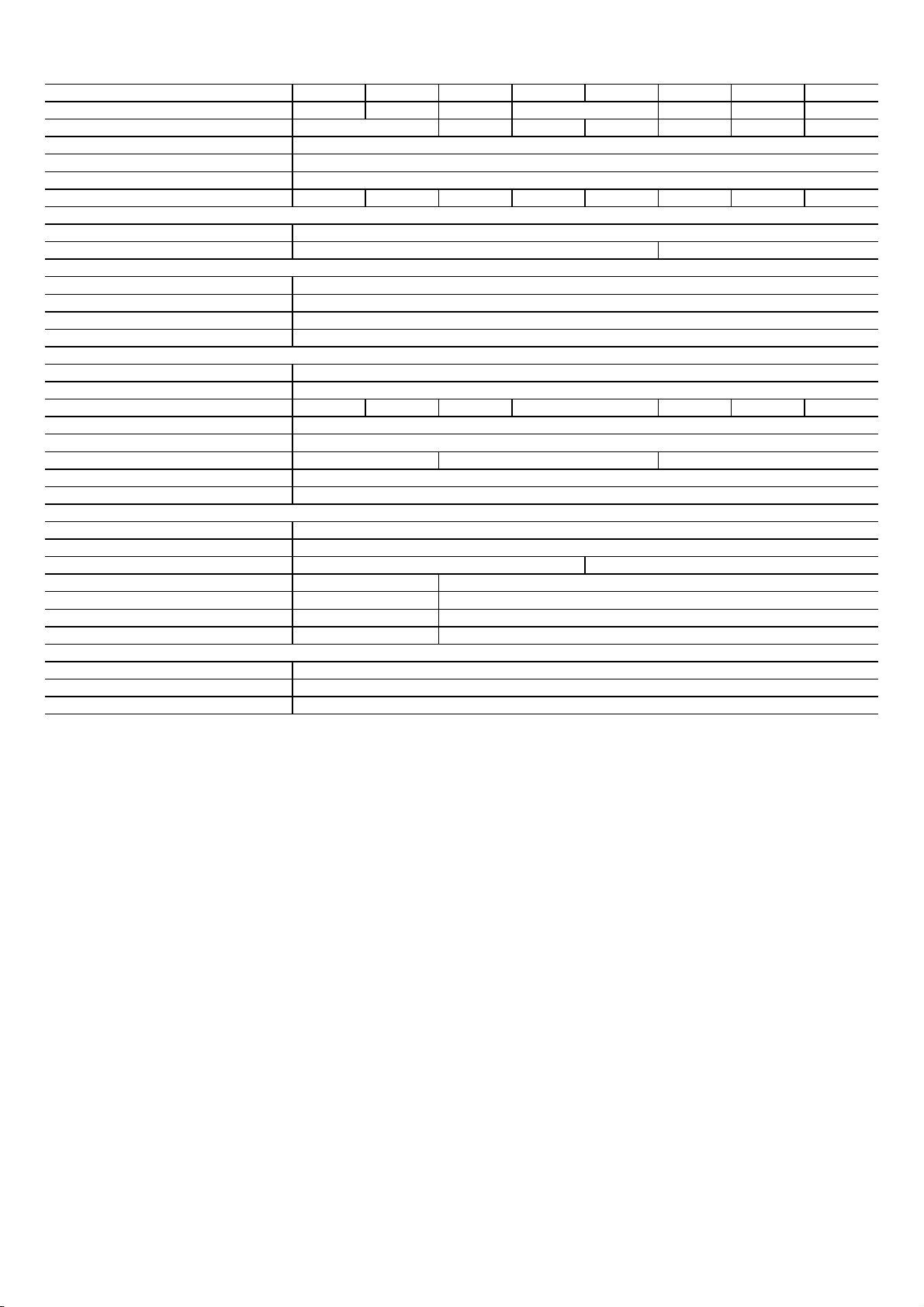
Physical Data
Unit Operating Weight Cool Only (kg) 81.9 86.5 87.5 86.1 91.1 100.9
Sound Power (dBA) 68.8 70.5 72.0 74.0 74.0 75.0 76.0 76.0
Compressor
Cool Only
High Pressure Switch (Trip / Reset) - PSIG
Refrigeration System*
Liquid Line
Motor Voltage
Motor Horsepower
Condenser Coil
Standard Coil Material (Pipes/Fins)
* For Long line application refer to Long Line Guide Line (Single Stage Only) - Avalilable in the Installation, Operation & Maintenance manual.
Page 3
38C Model 18 24 30 36-1Ph 36-3Ph 42 48 60
Unit Size (Tons) 1.5 2.0 2.5 3.5 4.0 5.0
62.0
Unit Color
Maximum Cooling Ambient (°F)
Minimum Cooling Ambient (°F)
Metering Device
Ducted Application
Low Pressure Switch (Trip / Reset) - PSIG
Nozzle In The Indoor Unit
3.0
Grey Enamel Finish
125
55
ScrollReciprocating
630 / 505
54 / 117
Refrigerant Type
Refrigerant Charge (kg) 2.31 2.44 3.12 4.05 4.17 4.52
Connection Type
Vapour Line
Max Length - ft
Max Lift - ft
Outdoor Fan
Motor Type
RPM
CFM
Diameter, No. Blades
Coil test Pressure (PSIG)
5/8" 3/4" 7/8"
220 - 240V 400 - 415V
920 940
2000 3000
18", 3 24", 3
1/10 1/4
Puron® R-410A
3.40
Sweat
3/8"
80
20
Permanent Split Capacitor
Cu/Al
400 - 450
Page 4
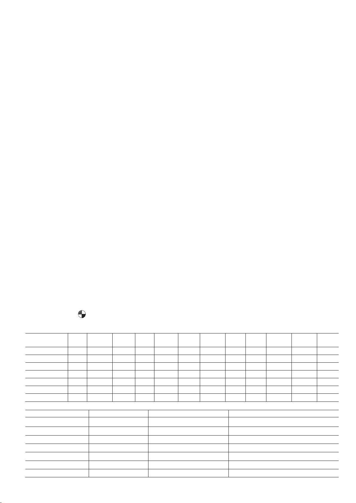
Base Unit Dimensions
38C
Model Size
18
587.4
722.3
95.2
15.8
112.7
458.8
198.4
71.4
12.7
304.8
298.4
317.5
30
792.2
808.0
98.4
19.0
166.7
627.1
231.8
74.6
15.9
406.4
393.7
349.2
36
792.2
981.1
98.4
19.0
166.7
627.1
231.8
74.6
15.9
406.4
393.7
393.7
42
792.2
722.3
98.4
22.2
166.7
627.1
231.8
74.6
15.9
406.4
393.7
323.8
48
792.2
722.3
98.4
22.2
166.7
627.1
231.8
74.6
15.9
406.4
393.7
323.8
792.2
808.0
98.4
22.2
166.7
627.1
231.8
74.6
15.9
406.4
393.7
349.2
38C Model Size
Unit Weight (Kgs.)
Shipping Weight (Kgs.)
Shipping Dimensions (L x W x H)
62.0 68.0
612.8 x 612.8 x 777.9
81.9 91.0
817.6 x 817.6 x 863.6
Page 4
Notes:
1. Allow 762.0 clearances to service side of unit, 1219.2 above unit, 152.4 on one side, 304.8 on remaining side
and 609.6 between units for proper air flow.
2. Center of gravity
3. All dimensions are in "mm" unless noted.
A B C D E F G K L M N P
24
587.4 722.3 95.2 15.8 112.7 458.8 198.4 71.4 12.7 304.8 298.4 317.5
60
18
24
30
36
42
48
60
Note: Shipping and Unit Weights are approximate.
62.0
86.5
86.1
91.1
100.9
68.0
96.0
95.0
100.0
110.0
612.8 x 612.8 x 777.9
817.6 x 817.6 x 1036.6
817.6 x 817.6 x 777.9
817.6 x 817.6 x 777.9
817.6 x 817.6 x 863.6
Page 5
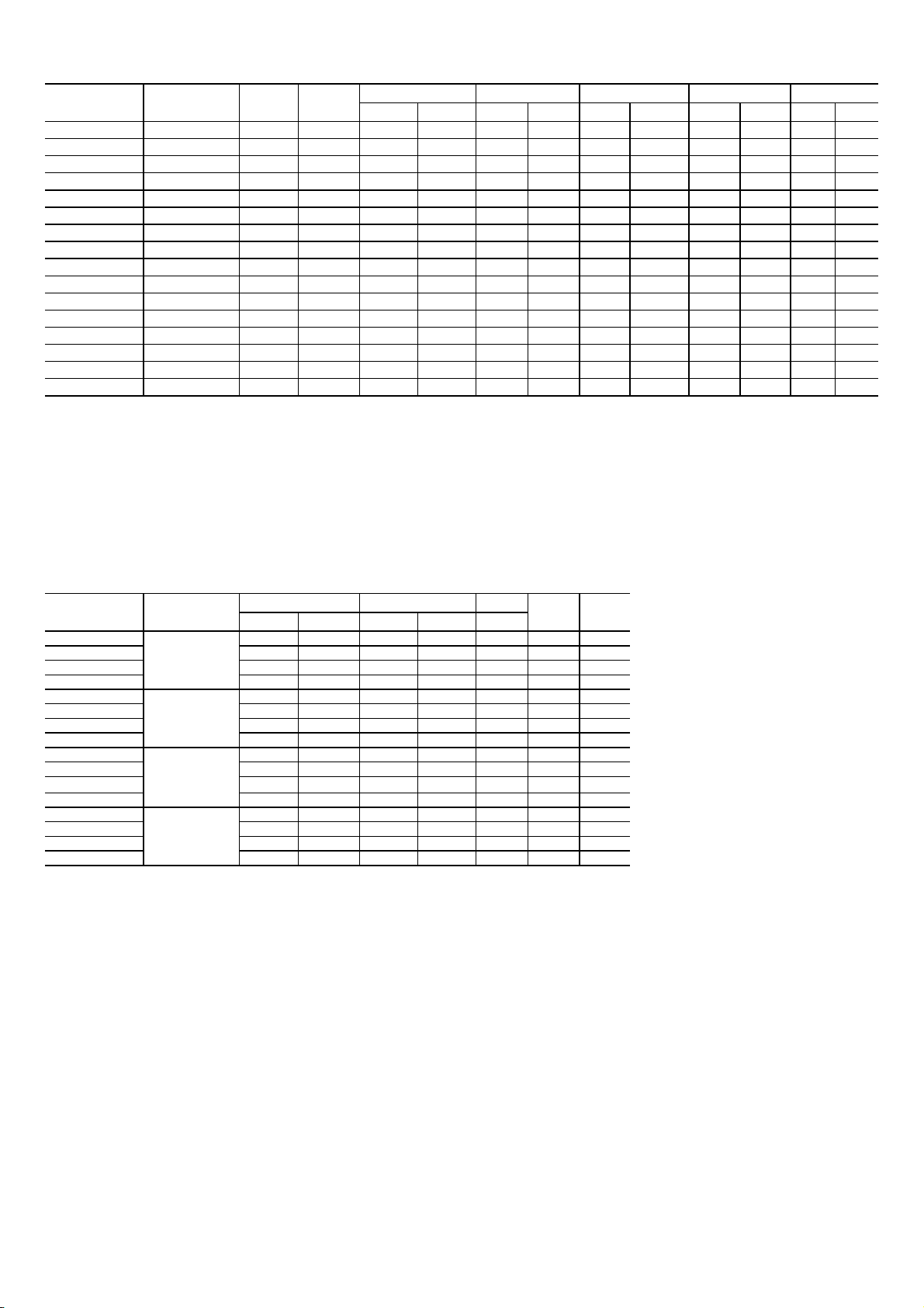
Combination Matrix and Ratings
T1 T3 T1 T3 T1 T3 T1 T3 T1 T3
18,800 16,500 11.8 9.0 1.593 1.833 4,301 1,833 7.5 8.5
CFM
EER
kWh/Yr
Legend for Electrical Data Table
MCA — Minimum Circuit Amps
Electrical Data
RLA — Rated Load Amps
FLA — Full Load Amps
Page 5
Outdoor Model Indoor Model
38CKPC18DS70 42TPM018-71 230/1/50 Ducted
38CKPC24DS70 42TPM024-71 230/1/50 Ducted
38CKPC30DS70 42TPM030-71 230/1/50 Ducted
38CKPC36DS70 42TPM036-71 230/1/50 Ducted
38CKPC36DS90 42TPM036-71 400/3/50 Ducted
38CKPS42DS90 42TPM042-71 400/3/50 Ducted
38CKPS48DS90 42TPM048-71 400/3/50 Ducted
38CKPS60DS90 42TPM060-71 400/3/50 Ducted
38CKPC18DS10 42TPM018-11 240/1/50 Ducted
38CKPC24DS10 42TPM024-11 240/1/50 Ducted
38CKPC30DS10 42TPM030-11 240/1/50 Ducted
38CKPC36DS10 42TPM036-11 240/1/50 Ducted
38CKPC36DS40 42TPM036-11 415/3/50 Ducted
38CKPS42DS40 42TPM042-11 415/3/50 Ducted
38CKPS48DS40 42TPM048-11 415/3/50 Ducted
38CKPS60DS40 42TPM060-11 415/3/50 Ducted
Legend for Combination Matrix and Ratings
— Cubic Feet per Minute
— Energy Efficiency Ratio
— kilowatt-hour/Year
Annual Consumption @ T1 kWh/Year — 2,700 x T1
Annual Consumption @ T3 kWh/Year — 1,000 x T3
Notes: Testing as per ISO 13253 testing standard at T1 and T3 conditions.
Voltage
Indoor
Type
Capacity (Btu/hr)
25,000 21,500 11.8 8.8 2.119 2.443 5,721 2,443 9.5 10.8
33,000 28,500 12.0 9.0 2.750 3.167 7,425 3,167 12.0 13.8
37,000 32,500 12.2 9.5 3.033 3.421 8,189 3,421 13.2 15.2
37,000 32,500 12.2 9.5 3.033 3.421 8,189 3,421 5.0 5.7
42,000 39,500 12.7 9.6 3.307 4.115 8,929 4,115 5.5 6.5
47,500 43,000 12.2 9.0 3.893 4.778 10,511 4,778 6.6 7.8
60,000 51,000 11.8 8.3 5.085 6.145 13,730 6,145 8.5 10.0
18,800 16,500 11.5 9.0 1.628 1.833 4,396 1,833 7.5 8.4
25,000 21,500 11.8 9.0 2.119 2.389 5,721 2,389 9.5 10.8
33,000 28,500 12.0 9.0
37,000 32,500 12.2 9.5 3.033 3.421 8,189 3,421 13.2 15.2
37,000 32,500 12.2 9.5 3.033 3.421 8,189 3,421 5.0 5.7
42,000 39,500 12.7 9.6 3.307 4.115 8,929 4,115 5.5 6.5
47,500 43,000 12.2 9.0 3.893 4.778 10,511 4,778 6.6 7.8
60,000 51,000 11.8 8.3 5.085 6.145 13,730 6,145 8.5 10.0
EER (Btu/hr) / W Power Input (kW) AMPS
2.750 3.167 7,425 3,167 12.0 13.8
kWh/Yr
Outdoor Model
38CKPC18DS10 207 253 6.2 48.0 0.52 8.3 15
38CKPC24DS10 207 253 8.6 48.0 0.52 11.3 15
38CKPC30DS10 207 253 11.4 64.0 1.50 15.8 25
38CKPC36DS10 207 253 12.8 64.0 1.50 17.5 30
38CKPC18DS70 207 253 6.2 48.0 0.52 8.3 15
38CKPC24DS70 207 253 8.6 48.0 0.52 11.3 15
38CKPC30DS70 207 253 11.4 64.0 1.50 15.8 25
38CKPC36DS70 207 253 12.8 64.0 1.50 17.5 30
38CKPC36DS40 360 440 4.5 35.0 0.80 6.4 15
38CKPS42DS40 360 440 6.8 43.0 0.80 9.3 15
38CKPS48DS40
38CKPS60DS40 360 440 9.5 67.1 0.80 12.7 20
38CKPC36DS90 360 440 4.5 35.0 0.80 6.4 15
38CKPS42DS90 360 440 6.8 43.0 0.80 9.3 15
38CKPS48DS90 360 440 7.1 52.0 0.80 9.7 15
38CKPS60DS90 360 440 9.5 67.1 0.80 12.7 20
LRA — Locked Rotor Amps
MOCP — Maximum Overcurrent Protection
Power Supply
(V/Ph/Hz)
240/1/50
230/1/50
415/3/50
400/3/50
Voltage Compressor
Min Max RLA LRA FLA
360 440 7.1 52.0 0.80 9.7 15
FAN
MCA MOCP
Page 6

Typical Wiring Schematic
38CKP18-24-30-36 (230V/240V-1PH-50Hz) - Ducted
38CKP36-42-48-60 (400V/415V-3PH-50Hz) - Ducted
Page 6
Page 7

Typical Wiring Schematic (Continued)
38CKP36-42-48-60 (400V/415V-3PH-50Hz) – Ducted With Capacitor Bank
Page 7
Page 8
Installation
Page 8
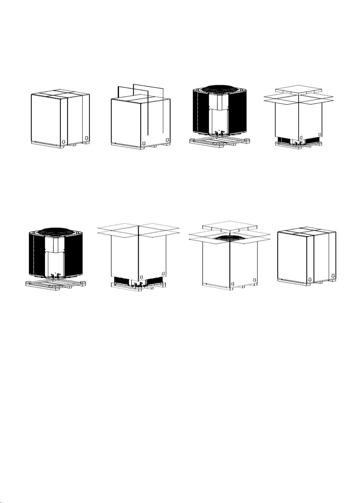
Un-Packing Instructions
1. Prepare unit for unpacking
2. Remove two (2) pcs. Plastic straps.
3. Open carton flaps and remove top pad then lift carton box.
4. Remove unit from wood pallet and install according to installation procedures.
Packing Instructions
1. Place the unit on the wooden pallet.
2. Put the carton box from the top of the unit
3. Place the top pad on top of the unit.
4. Close the carton box and strap the unit.
at site of final installation.
Fig.1 Un-packing Instructions
Fig.2 Packing Instructions
Installation Recommendations
NOTE: In some cases noise in the living area has been traced to gas pulsations from improper installation of
equipment.
1. Locate unit away from windows, patios, decks, and so forth, where unit operation sound may disturb
customer.
2. Insure that vapor and liquid tube diameters are appropriate to capacity of unit.
3. Run refrigerant tubes as directly as possible by avoiding unnecessary turns and bends.
4. Leave some slack between structure and unit to absorb vibration.
5. When passing refrigerant tubes through the wall, seal opening with RTV or other pliable silicon based caulk.
(See Fig. 3.)
6. Avoid direct tubing contact with water pipes, duct work, floor joists, wall studs, floors, and walls.
7. Do not suspend refrigerant tubing from joists and studs with a rigid wire or strap that comes in direct contact
with tubing. (See Fig. 3.)
8. Ensure that tubing insulation is pliable and completely surrounds vapor tube.
9. When necessary, use hanger straps which are 1 in. wide and conform to shape of tubing insulation. (See
Fig. 3.)
10. Isolate hanger straps from insulation by using metal sleeves bent to conform to shape of insulation.
Page 9
ELECTRICAL SHOCK HAZARD
Warning
Page 9
Fig. 3 Connecting Tubing Installation
Step 1 — Complete Pre-Installation Checks
Unpack Unit—Move unit to final location. Follow unpacking instructions as shown in manual, being careful not to
damage service valves or grilles.
Inspect Shipment — File claim with shipping company if shipment is damaged or incomplete. Check unit nameplate
to ensure unit matches job requirements. CONSIDER SYSTEM REQUIREMENTS — Consult local building codes
and NEC for special installation requirements. Allow sufficient space for airflow clearance, wiring, refrigerant piping,
and servicing unit. See Unit Dimensional Drawing. Unit can be mounted on a level pad directly on base legs or
mounted on raised pads at support points.
Failure to follow this warning could result in personal injury or death.
Before installing, modifying, or servicing system, main electrical disconnect switch must be in the OFF position.
There may be more than 1 disconnect switch. Lock out and tag switch with a suitable warning label.
Step 2 — Rig and Mount Unit
Location — Check local codes for regulations concerning zoning, noise, platforms, and other issues.
Locate unit away from fresh air intakes, vents, or bedroom windows. Noise may carry into the openings and disturb
people inside. Locate unit in a well drained area, or support unit high enough so that water runoff will not enter the
unit. Locate unit away from areas where heat, lint, or exhaust fumes will be discharged onto unit (as from dryer
vents). Locate unit away from recessed or confined areas where recirculation of discharge air may occur (refer to
CLEARANCES section of this document). Roof-top installation is acceptable providing the roof will support the unit
and provisions are made for water drainage and noise/vibration dampening.
Rigging — Keep unit upright. Lift unit using sling. Use cardboard or padding under sling, and spreader bars to
prevent sling damage to unit. See Fig. 4 Install unit so coil does not face into prevailing winds, all panels must be in
place when rigging.
Mounting on Ground — Mount unit on a solid, level concrete pad. Position unit so water from roof does not fall
directly into unit. Accessory stacking kits can be used when units are to be stacked. If conditions or local codes
require unit to be fastened to a pad, field- supplied tie down bolts should be used and fastened through slots
provided in unit mounting feet. See Fig. 5, Fig. 6.
Mounting on Rooftop / Ground — Mount unit on level platform or frame at least 6 in. On roof surface, isolate unit
and tubing from structure.
Install on solid, level mounting pad — If conditions or local codes require the unit be attached to pad, tie down bolts
should be used and fastened through knockouts provided in the unit base pan. Refer to unit mounting pattern
below to determine base pan size and knockout hole location. Arrange supporting members to adequately support
unit and minimize transmission of vibration to building. Consult local codes governing rooftop applications.
Page 10
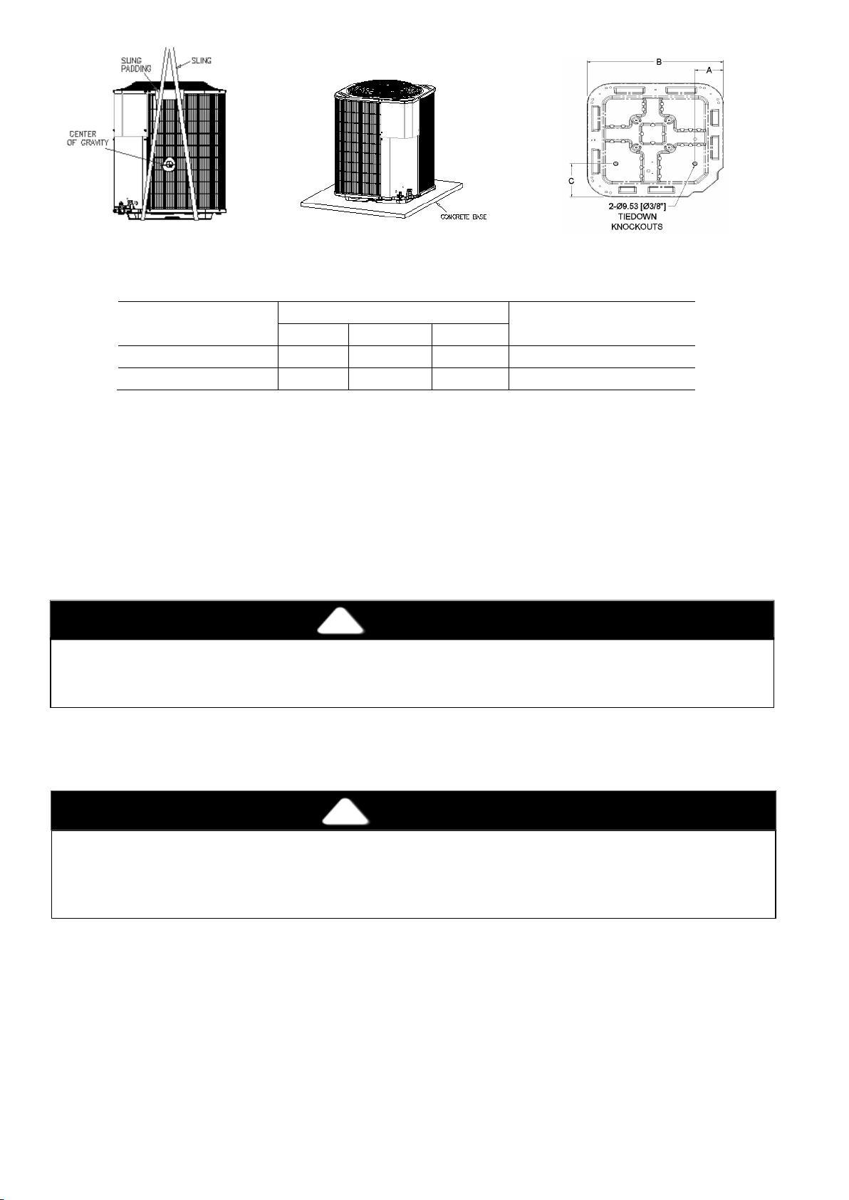
Width x Dept (mm)
A B C
596.9 x 596.9
111.0
458.8
182.6
660 x 660
800.1 x 800.1
166.7
627.1
231.8
889 x 889
R-410A systems operate at higher pressures than standard R-22 systems. Do not use R-22 service equipment
Caution
Do not bury more than 36 in. of refrigerant pipe in the ground. If any section of pipe is buried, there must be a 6
Warning
With Sling
Mounting
Knockouts
Page 10
Fig – 4: Lifting Unit
Fig – 5: Rooftop/Ground
Fig – 6: Tie Down
Base Pan
Clearance requirements — When installing, allow sufficient space for airflow clearance, wiring, refrigerant piping,
and service. Allow 30 in. (762.0 mm) clearance to service end of unit and 48 in. (1219.2 mm) (above unit. For
proper airflow, a 6-in. (152.4 mm) clearance on 1 side of unit and 12-in. (304.8 mm) on all remaining sides must
be maintained. Maintain a distance of 24 in. (609.6 mm) between units or 18 in. (457.2 mm) if no overhang within
12 ft. (3.66 m). Position so water, snow, or ice from roof or eaves cannot fall directly on unit. On rooftop
applications, locate unit at least 6 in. (152.4 mm) above roof surface.
Tie Down Knockouts (mm)
Tie Down Knockouts
Minimum Mounting Pad
Dimensions (mm)
Operating Ambient — The minimum outdoor operating ambient in cooling mode is 55°F (12.78°C), and the
maximum outdoor operating ambient in cooling mode is 125°F (51.67°C).
Step 3—Complete Refrigerant Piping Connections
or components on R-410A equipment. No other refrigerant may be used in this system. Gage set, hoses, and
recovery system must be designed to handle R-410A. If you are unsure consult the equipment manufacturer.
Outdoor units may be connected to indoor units using field-supplied tubing of refrigerant
use less than 10 ft. of interconnecting tubing. When more than 80 ft. of interconnecting tubing and more than 20 ft.
of vertical lift is used, refer to Long Line Guideline Section.
in. vertical rise to the valve connections on the outdoor unit. If more than the recommended length is buried,
refrigerant may migrate to the cooler, buried section during extended periods of system shutdown. This causes
refrigerant slugging and could damage compressor at start-up.
If either refrigerant tubing or indoor coil is exposed to atmospheric conditions for longer than 5 minutes, it must be
evacuated to 500 microns to eliminate contamination and moisture in the system.
Run refrigerant tubes as directly as possible, avoiding unnecessary turns and bends. Suspend refrigerant tubes so
they do not damage insulation on vapor tube and do not transmit vibration to the structure. Also, when passing
refrigerant tubes through the wall, seal opening so that vibration is not transmitted to structure. Leave some slack in
refrigerant tubes between structure and outdoor unit to absorb vibration. Refer to separate indoor unit installation
instructions for additional information.
Outdoor Unit Connected To Factory Approved Indoor Unit Outdoor — Unit contains correct system refrigerant
charge for operation with indoor unit of same size when connected by 25 ft. (7m) of field supplied or factory
accessory tubing. Check refrigerant charge for maximum efficiency.
Make Piping Sweat Connections — Remove plastic caps from liquid and suction service valves. Use refrigerant
grade tubing. Service valves are closed from the factory and ready for brazing. After wrapping the service valve
grade and condition. Do not
Page 11
with a wet cloth, the tubing set can be brazed to the service valve using either silver bearing or non-silver
To avoid damage while brazing, service valves should be wrapped in a heat sinking material such as a wet
Caution
Unit cabinet must have an uninterrupted, unbroken electrical ground to minimize the possibility of personal injury
Warning
Caution
The unit cabinet must have an uninterrupted or unbroken ground. The ground may consist of electrical wire or
Warning
Page 11
bearing brazing material. Consult local code requirements. Refrigerant tubing and indoor coil are ready for leak
testing; this check should include all field and factory joints. NOTE: Unit is shipped with R-410A Holding factory
charge indicated on nameplate. Pass nitrogen or other inert gas through piping while brazing to prevent formation of
copper oxide.
cloth. When Brazing tubing sets to service valves, a brazing shield must be used to prevent damage to the
painted unit surface.
Step 4 — Make Electrical Connections
if an electrical fault should occur. This ground may consist of electrical wire connected to the unit ground lug in
control compartment, or conduit approved for electrical ground when installed in accordance with NEC,
ANSI/NFPA 70 (American National Standards Institute/National Fire Protection Association), and local electrical
codes. Failure to follow this warning could result in the installer being liable for personal injury to others.
Unit failure as a result of operation on improper line voltage or excessive phase imbalance constitutes abuse and
may cause damage to electrical components. Such operation will invalidate any applicable Carrier warranty.
Power Wiring — Unit is factory-wired for voltage shown on nameplate. Provide adequate, fused disconnect switch
within sight of unit, readily accessible but out of reach of children. Provision for locking the switch open (off) is
advisable to prevent power from being turned on while unit is being serviced. Disconnect switch, fuses, and field
wiring must be in compliance with NEC and applicable local codes. Use minimum 85 C wires for field power
connection. Route power wires through opening in the unit side panel and connect in unit control box. Unit must be
grounded
Route Ground And Power Wires — Remove access panel to gain access to unit wiring. Extend wires from
disconnect through power wiring hole provided and into unit control box. See Electrical Data Table and unit label
diagram for field-supplied wiring details.
Connect Ground And Power Wires — Connect ground wire to ground connection in control box for safety.
NOTE: Operation of unit on improper line voltage constitutes abuse and could affect unit reliability. See unit rating
plate. Do not install unit in system where voltage or phase imbalance (3 phase) may fluctuate above or below
permissible limits. Do not install unit in system where voltage may fluctuate above or below permissible limits. When
making electrical connections, provide clearance at unit for refrigerant piping connections.
NOTE: Use copper wires only between disconnect switch and unit.
NOTE: Install branch circuit disconnect of adequate size per NEC to handle unit starting current. Locate disconnect
within sight from and readily accessible from unit.
Connect Control Wiring — Route 24v control wires through control wiring and connect leads to control wiring. Use
No. 18 AWG color coded, insulated (35°C minimum) wire. If thermostat is located more than 100 ft from unit, as
measured along the control voltage wires, use No. 16 AWG color coded wire to avoid excessive voltage drop.
metal conduit when installed in accordance with existing electrical codes.
Page 12
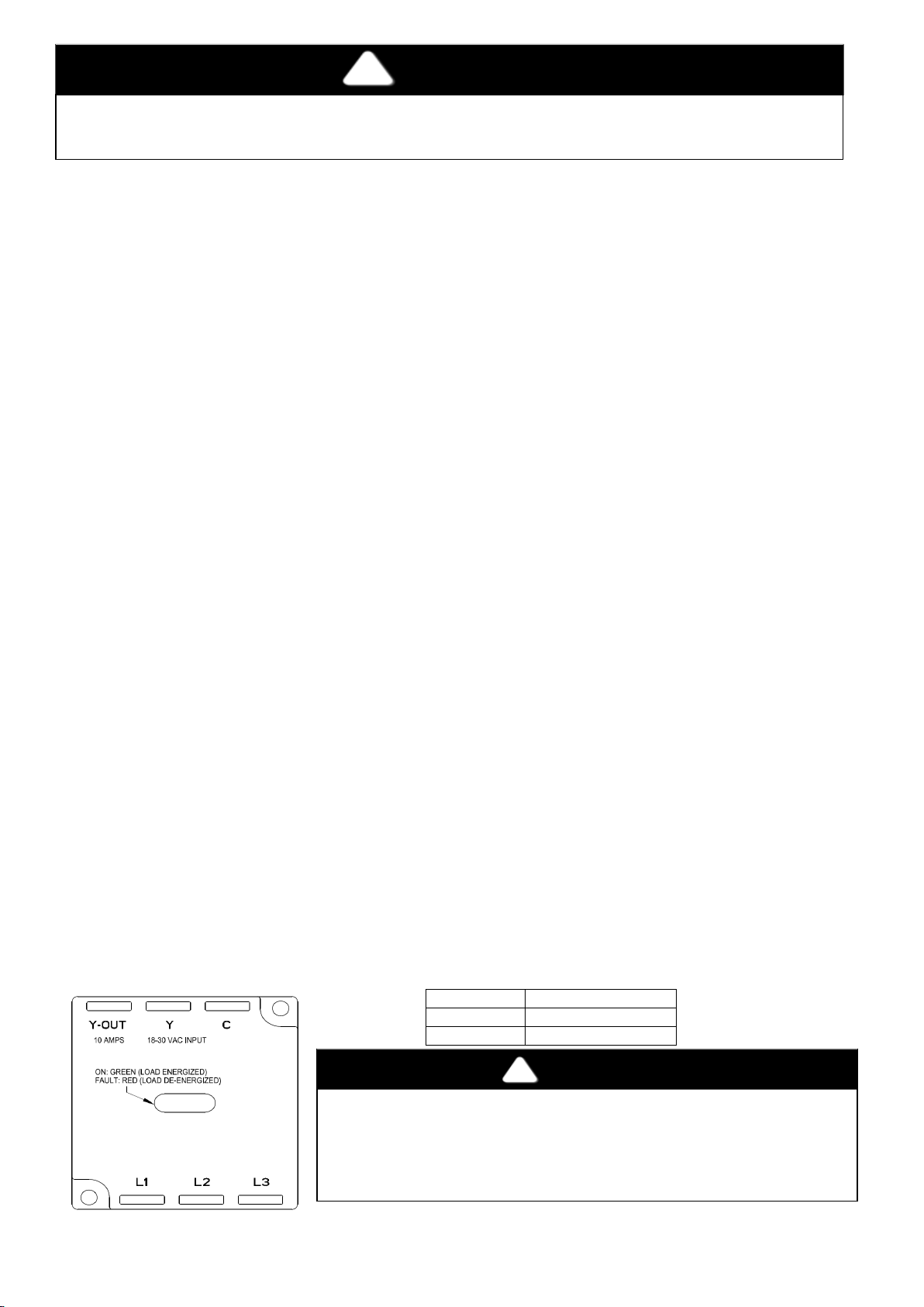
LED
Status
Green
Load Energized
Red
Load De-Energized
Before performing service or maintenance, be sure the indoor unit main power switch is off and indoor blower
has completely stopped. Do not supply power to unit with compressor terminal box cover removed. Failure to
do so may result in electrical shock or injury from rotating fan blades.
Warning
Caution
Page 12
Compressor Crankcase Heater — A crankcase heater is required if refrigerant tubing is longer than 80 ft. (24.38 m).
When equipped with a crankcase heater, energize heater a minimum of 24 hours before starting unit. To energize
heater only, set thermostat to OFF mode and close electrical disconnect to outdoor unit.
Install Electrical Accessories — Refer to individual instructions packaged with kits or accessories when installing.
Start-Up
Preliminary Checks
1. Check that all the internal wiring connections are tight and that barriers, covers and panels are in place.
2. Make certain field electrical power source agrees with unit nameplate and rating.
3. Open all service valves.
Leak Test — Field piping and fan coil must be leak tested by pressure method described in Carrier Standard Service
Techniques Manual, Chapter 1, Section 1-6.
Evacuate and Dehydrate— Field piping and fan coil must be evacuated and dehydrated by either of the methods
described in Carrier Standard Service Techniques Manual, Chapter 1, Section 1-7.
Charge System — Release factory charge into system by opening (back seating) liquid and suction line service
valves. Add charge amount as required for the total system. Refer to separate indoor unit installation instructions for
the required total system charge when connected to the indoor unit.
Percentage decrease in capacity due to Maximum Line Lengths, Please refer to Long Line Guideline.
To Start Unit
NOTE: Please use the Pre-startup and Startup included with the fan coil units for correct start-up procedures. Be
sure that field disconnect is closed. Set room thermostat below ambient temperature. Operate unit for 15 minutes,
then check system refrigerant charge.
Sequence Of Operation
Turn on power to indoor and outdoor units. Transformer is energized. On a call for cooling, thermostat makes circuits
Y1-Y2 and L-N. Three phase models are equipped with a phase monitor to detect if the incoming power is correctly
phased for compressor operation. If the phasing is correct, circuit Y1-Y2 energizes contactor, starting outdoor fan
motor and compressor circuit. L-N energizes indoor unit blower relay, starting indoor blower motor on high speed.
NOTE: If the phasing is incorrect, the contactor will not be energized. To correct the phasing, interchange any two of
the three power connections on the field side.
When thermostat is satisfied, its contacts open, de-energizing contactor and blower relay. Compressor and motors
stop.
• 3-phase scroll compressors are rotation sensitive.
• A red LED on phase monitor indicates reverse rotation.
• This will not allow contactor to be energized.
• Disconnect power to unit and interchange 2 field wiring leads on
Fig. 7 Three Phase Monitor Control
Page 13
Service
The 38C unit coils hold only the factory designated amount of refrigerant. Additional refrigerant may cause
Caution
Warning
Do not leave system open to atmosphere. Product damage could occur. Compressor oil is highly susceptible to
Caution
The compressor used in this product is specifically designed to operate with R-410A refrigerant and cannot be
Caution
Page 13
Before performing service or maintenance, be sure the indoor unit main power switch is off and indoor blower
has completely stopped. Failure to do so may result in electrical shock or injury from rotating fan blades.
moisture absorption.
interchanged.
Outdoor Fan— A reinforced wire mount holds the outdoor fan assembly in place.
Compressor Pressure Relief Valve — Valve is located in compressor. Relief valve opens at a pressure differential of
approximately 600 ± 50 psig between suction (low side) and discharge (high side) to allow pressure equalization.
Internal Current and Temperature Sensitive Overload — Control resets automatically when internal compressor
motor temperature drops to a safe level (overloads may require up to 45 minutes to reset). When an internal
overload is suspected of being open, check by using an ohmmeter or continuity tester. If necessary, refer to Carrier
Standard Systems Techniques Manual, Chapter 2, for complete information.
Pump down Procedure — Service valves provide a convenient shut-off valve useful for certain refrigeration system
repairs. System may be pumped down to make repairs on low side without losing complete refrigerant charge.
1. Attach pressure gage to suction service valve gage port.
2. Front seat the liquid line valve.
3. Start unit in cooling mode. Run until low-pressure switch opens at 54 psig (472Kpa). Do not allow compressor
to pump to a vacuum.
4. Shut unit off and front seat suction valve.
5. Depressurize low side of unit and recover refrigerant following accepted practice.
Filter Drier – The filter drier is specifically designed to operate with R-410A, use only factory-authorized components.
When removing a filter drier, use a tubing cutter to cut drier from system. Do not unsweat a filter drier from system.
Heat from unsweating will release moisture and contaminants from drier into the system.
units to relieve pressure through compressor internal pressure relief valve (indicated by sudden rise of suction
pressure) before suction pressure reaches 5 pisg. If this occurs, shut off immediately, then front seat the
suction valve and remove and recover excess refrigerant following accepted practice.
Loss of Charge Pressure Switch — This switch, mounted on the suction line, has fixed non-adjustable settings. To
check pressure switch, attach pressure gage to suction service valve gage port. Slowly close liquid shutoff valve and
allow compressor to pump down. Do not allow compressor to pump down below 2 psig. Compressor should shut
down when suction pressure drops to cutout pressure in Physical Data Table, and should restart when pressure
builds up to cut-in pressure shown in Physical Data Table.
High Pressure Switch — This switch, mounted on the discharge line, has fixed non- adjustable settings & auto
reset. To check pressure switch, attach pressure gauge to compressor discharge service port, block condenser coil,
monitor pressure till compressor trips, remove blockage and observe at which pressure compressor restarts.
Page 14

If the compressor does not trip at the cut-out pressure (630 psig), remove the blockage immediately and
contact your local Carrier service center.
Caution
The compressor in this system uses a polyol ester (POE) oil Mobil EAL ARTIC 22CC. This oil is extremely
Caution
Before performing service or maintenance, be sure the indoor unit main power switch is off and indoor blower
Warning
Warning
Due to the high pressure of nitrogen, it should never be used without a pressure regulator on the tank. Failure
to follow this warning can cause a fire, personal injury, or death.
Warning
Page 14
Service Valves — The service valves in the outdoor unit come from the factory front seated. This means the
refrigerant charge is isolated from the line-set connection ports. To prevent damage to the valve, use a wet cloth or
other acceptable heat sink material on the valve before brazing. The service valves must be back seated (turned
counterclockwise until seated) before the service port caps can be removed and the hoses of the gage manifold
connected. In this position, refrigerant has access from the through outdoor and indoor unit. The service valve
cannot be field repaired; only a complete valve or valve stem seal and service port caps are available for
replacement.
Maintenance
hygroscopic, meaning it absorbs water readily. POE oils can absorb 15 times as much water as other oils
designed for HCFC and CFC refrigerants. Take all necessary precautions to avoid exposure of the oil to the
atmosphere.
has completely stopped. Failure to do so may result in electrical shock or injury from rotating fan blades.
Lubrication Compressor — Compressor contains factory oil charges; replace oil when lost. Refer to Carrier Standard
Service Techniques Manual, for oil recharging procedure.
Cleaning Coils — Coil should be washed out with water or blown out with compressed air. Note that the blow-thru
design causes dirt and debris to build up on the inside of the coils. Clean coil annually or as required by location and
outdoor air conditions. Inspect coil monthly and clean as required. Fins are NOT continuous through coil sections.
Dirt and debris may pass through the first section, become trapped between the rows of fins, and restrict condenser
airflow. Use a flashlight to determine if dirt or debris has collected between coil sections.
Clean coil as follows:
Turn off unit power. Use a garden hose or other suitable equipment to flush coil from the outside to remove dirt. Be
sure to flush all dirt and debris from drain holes in the base of unit. Fan motors are waterproof.
Do not use harsh chemicals for cleaning coils, use only water, compressed air or Carrier approved coil
cleaners.
Leak Detection — New installations should be checked for leaks prior to complete charging. If a system has lost all
or most of its charge, system must be pressurized again to approximately 150 lb minimum. This can be done by
adding refrigerant using normal charging procedures or by pressurizing system with nitrogen (less expensive than
refrigerant). Nitrogen also leaks faster than R-410A. Nitrogen cannot, however, be detected by an electronic leak
detector.
Page 15
Assuming that a system is pressurized with either all refrigerant or a mixture of nitrogen and refrigerant, leaks in the
R410a refrigerant must be added to a system as a liquid since it is a blend. Adding liquid into suction service
Caution
Page 15
system can be found with an electronic leak detector that is capable of detecting HFC refrigerant. If system has been
operating for some time, make first check for a leak visually. Since refrigerant carries a small quantity of oil, traces of
oil at any joint or connection is an indication that refrigerant is leaking at that point. A simple and inexpensive method
of testing for leaks is to use soap bubbles. Any solution of water and soap may be used. Soap solution is applied to
all joints and connections in system. A small pinhole leak is located by tracing bubbles in soap solution around leak.
If the leak is very small, several minutes may pass before a bubble will form.
R-410A Refrigerant Charging — Refer to unit information plate for superheat charging procedure. R-410A
refrigerant cylinders contain a dip tube which allows liquid refrigerant to flow from cylinder in upright
position. Charge R-410A units with cylinder in upright position and a commercial type metering device in the
manifold hose. Charge refrigerant into suction-line. For all approved combinations, system must be charged correctly
for normal system operation and reliable operation of components. If system has lost all charge, weigh in charge
using dial-a-charge designed for R-410A refrigerant or digital scale. System charge should be fine-tuned by using
superheat method.
port using a flow metering device for throttling it in slowly to avoid slugging the compressor or diluting and
washing out the compressor oil.
CHECK CHARGE
Factory charge amount is shown on unit rating plate.
Cooling Only Procedure
NOTE: If superheat or subcooling charging conditions are not favorable, charge must be weighed in accordance with
unit rating plate ±0.6 oz/ft of 3/8-in. (56g/m of 9.5 mm) liquid line above or below 25 ft (7.6 m) respectively.
EXAMPLE:
Charging Formula:
[(Lineset oz/ft x total length) – (factory charge for lineset)] = charge adjustment
Example 1: System has 25ft of line set using existing 1/4“liquid line. What charge adjustment is required?
Formula: (.27 oz/ft x 25ft) – (13.5 oz) = -6.75 oz; (8.0 g/m x 7.6 m) – (382.7 g) = -321.9 g
Net result is to remove 6.75 oz of refrigerant from the system
Example 2: System has 45 ft of existing 5/16” liquid line. What is the charge adjustment?
Formula: (.40 oz/ft. x 45ft) – (13.5 oz.) = 9 oz; (11.8 g/m x 13.7m) – (382.7 g) = -221.0 g
Net result is to add 4.5 oz of refrigerant to the system
The following procedure is valid when indoor airflow is within ±21 percent of its rated CFM:
1. Operate unit a minimum of 10 minutes before checking charge.
2. Measure suction pressure by attaching an accurate gage to suction valve service port.
3. Measure suction temperature by attaching an accurate thermistor type or electronic thermometer to suction line
near service valve.
4. Measure outdoor air dry bulb temperature with thermometer.
5. Measure indoor air (entering indoor coil) wet bulb temperature with a sling psychrometer.
6. Refer to “Super Heat Charging Table”. Find outdoor temperature and evaporator entering air web bulb
temperature. At this intersection, note superheat.
7. Refer to “Required Suction Tube Temperature”. Find superheat temperature and suction pressure. At this
intersection note suction line temperature.
8. If a unit has a higher suction line temperature than charted temperature, add refrigerant until charted temperature
is reached.
9. If unit has a lower suction line temperature than charted temperature, reclaim refrigerant until charted temperature
is reached.
10. When adding refrigerant, charge in liquid form into suction service port using a flow--restricting device.
11. If outdoor air temperature or pressure at suction valve changes, charge to new suction line temperature indicated
on chart.
NOTE: If line length is beyond 80 ft (24.38 m) or greater than 20 ft (6.10 m) vertical separation, See Long Line
Guideline for special charging requirements.
Page 16
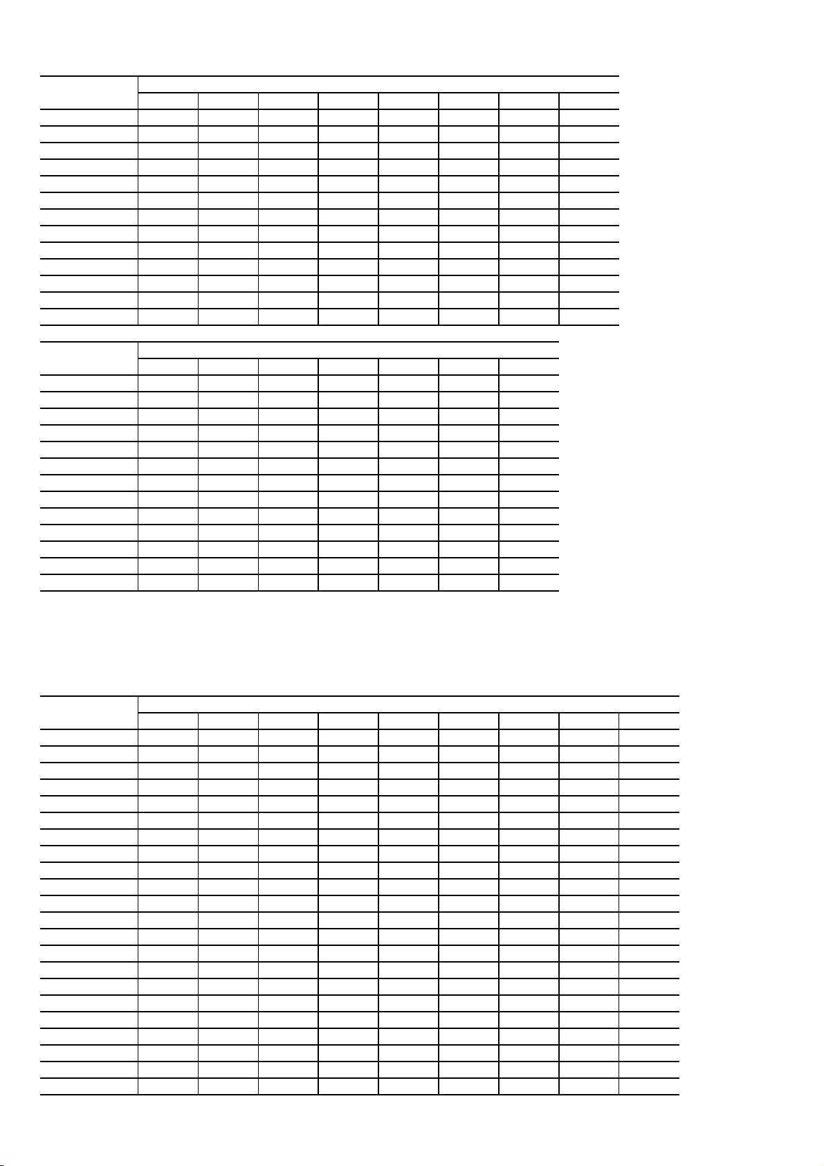
Superheat Charging Table
Required Suction Tube Temperature (°C)
Page 16
OUTDOOR
TEMP (°C) 10 11 12 13 14 15 16 17
13
16
18
21
24
27
29
32
35
38
41
43
46
OUTDOOR
TEMP (°C) 18 19 20 21
13
16
18
21
24
27
29
32
35
38
41
43
46
Where a dash (–) appears, do not attempt to charge system under these conditions, or refrigerant slugging may occur.
Charge must be weighed in.
5.0 6.7 7.8 9.4 11.1 11.9 12.8 14.4
3.9 5.6 6.7 8.3 10.0 10.8 11.7 13.3
– 3.3 5.6 7.2 8.9 9.7 10.6 11.7
– – 3.9 5.6 7.2 8.1 8.9 10.6
– – – 3.3 5.0 5.8 6.7 8.3
– – – – 2.8 3.6 4.4 6.7
– – – – – – – 4.4
– – – – – – – 2.8
– – – – – – – –
– – – – – – – –
– – – – – – – –
– – – – – – – –
– – – – – – – –
16.1 17.8 19.4 20.6 22.2 23.3 25.0
15.0 16.7 18.3 20.0 21.1 22.2 23.9
13.3 15.0 16.7 18.3 20.0 21.1 22.8
11.7 13.3 15.0 16.7 18.3 20.0 21.7
10.0 11.7 7.8 15.6 17.2 18.9 20.6
8.3 10.0 11.7 13.9 15.6 17.2 19.4
6.1 8.3 10.6 12.2 14.4 16.7 18.3
5.0 7.2 8.9 11.1 13.3 15.0 17.2
3.3 5.6 7.8 10.0 12.2 13.9 16.1
– 4.4 6.7 8.3 11.1 12.8 15.0
– 2.8 5.0 7.2 9.4 12.2 14.4
– – 3.3 6.1 8.3 11.1 13.9
– – – 4.4 7.8 10.0 12.8
EVAPORATOR ENTERING AIR (°C WB)
EVAPORATOR ENTERING AIR (°C WB)
22 23 24
NOTE: Superheat ° C is at low-side service port.
SUPERHEAT
TEMP (°C)
0
1
2
3
4
6
7
8
9
10
11
12
13
14
15
16
17
18
19
20
21
22
SUCTION PRESSURE AT SERVICE PORT (KPA)
743 774 805 836 869 902 957 971 1005
1.7 2.8 3.9 5.0 6.1 7.2 8.3 9.4 10.6
2.8 3.9 5.0 6.1 7.2 8.3
3.9 5.0 6.1 7.2 8.3 9.4 10.6 11.7 12.8
5.0 6.1 7.2 8.3 9.4 10.6 11.7 12.8 13.9
6.1 7.2 8.3 9.4 10.6 11.7 12.8 13.9 15.0
7.2 8.3 9.4 10.6 11.7 12.8 13.9 15.0 16.1
8.3 9.4 10.6 11.7 12.8 13.9 15.0 16.1 17.2
9.4 10.6 11.7 12.8 13.9 15.0 16.1 17.2 18.3
10.6 11.7 12.8 13.9 15.0 16.1 17.2 18.3 19.4
11.7 12.8 13.9 15.0 16.1 17.2 18.3 19.4 20.6
12.8 13.9 15.0 16.1 17.2 18.3 19.4 20.6 21.7
13.9 15.0 16.1 17.2 18.3 19.4 20.6 21.7 22.8
15.0 16.1 17.2 18.3 19.4 20.6 21.7 22.8 23.9
16.1 17.2 18.3 19.4 20.6 21.7 22.8 23.9 25.0
16.7 17.8 18.9 20.0 21.1 22.2 23.3 24.4 25.6
2 18.3 19.4 20.6 21.7 22.8 23.9 25.0 26.1
17.
18.3 19.4 20.6 21.7 22.8 23.9 25.0 26.1 27.2
19.4 20.6 21.7 22.8 23.9 25.0 26.1 27.2 28.3
20.6 21.7 22.8 23.9 25.0 26.1 27.2 28.3 29.4
21.7 22.8 23.9 25.0 26.1 27.2 28.3 29.4 30.6
22.8 23.9 25.0 26.1 27.2 28.3 29.4 30.6 31.7
23.9 25.0 26.1 27.2 28.3 29.4 30.6 31.7 32.8
9.4 10.6 11.7
Page 17
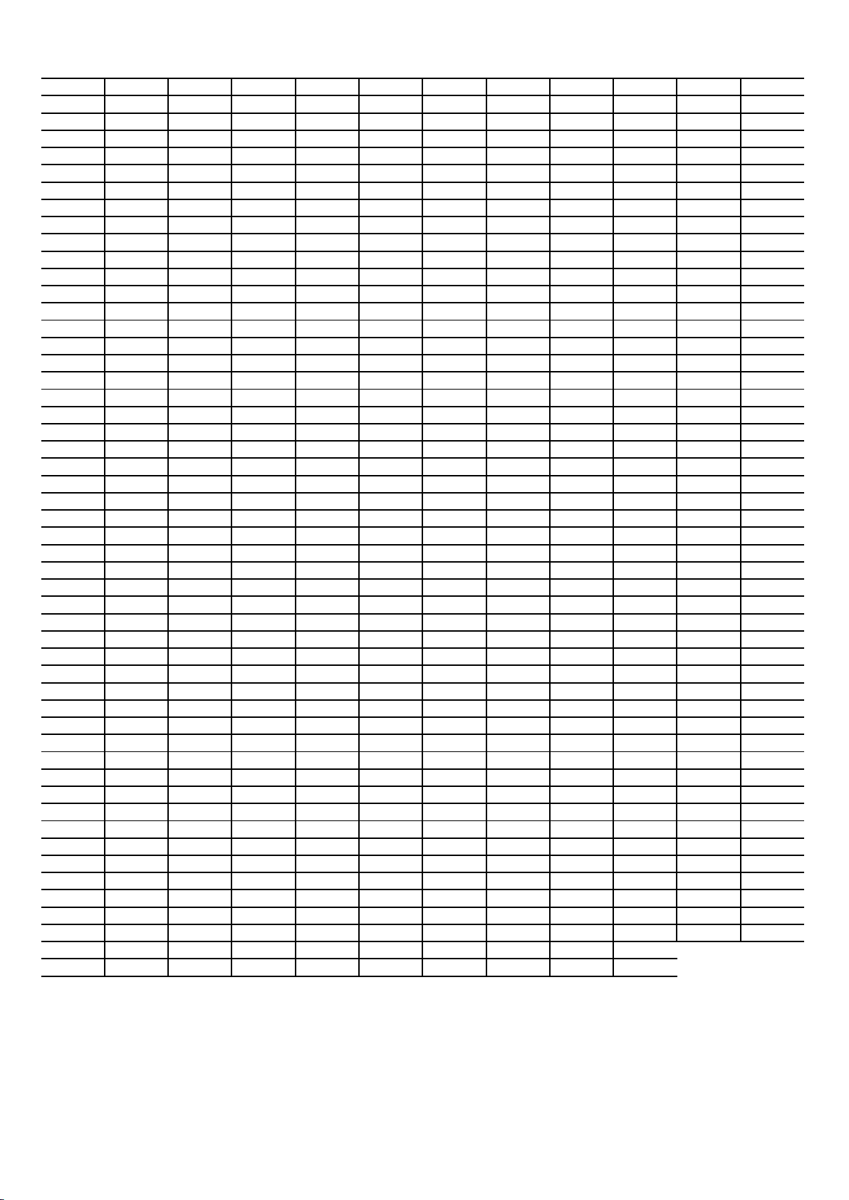
Pressure vs. Temperature Chart R-410A
Page 17
PSIG °F PSIG °F PSIG °F PSIG °F PSIG °F PSIG °F
12 -37.7 114 37.8 216 74.3 318 100.2 420 120.7 522 137.6
14 -34.7 116 38.7 218 74.9 320 100.7 422 121.0 524 137.9
16 -32.0 118 39.5 220 75.5 322 101.1 424 121.4 526 138.3
18 -29.4 120 40.5 222 76.1 324 101.6 426 121.7 528 138.6
20 -36.9 122 41.3 224 76.7 326 102.0 428 122.1 530 138.9
22 -24.5 124 42.2 226 77.2 328 102.4 430 122.5 532 139.2
24 -22.2 126 43.0 228 77.8 330 102.9 432 122.8 534 139.5
26 -20.0 128 43.8 230 78.4 332 103.3 434 123.2 536 139.8
28 -17.9 130 44.7 232 78.9 334 103.7 436 123.5 538 140.1
30 -15.8 132 45.5 234 79.5 336 104.2 438 123.9 540 140.4
32 -13.8
34 -11.9 136 47.1 238 80.6 340 105.1 442 124.6 548 141.6
36 -10.1 138 47.9 240 81.1 342 105.4 444 124.9 552 142.1
38 -8.3 140 48.7 242 81.6 344 105.8 446 125.3 556 142.7
40 -6.5 142 49.5 244 82.2 346 106.3 448 125.6 560 143.3
42 -4.5 144 50.3 246 82.7 348 106.6 450 126.0 564 143.9
44 -3.2 146 51.1 248 83.3 350 107.1 452 126.3 568 144.5
46 -1.6 148 51.8 250 83.8 352 107.5 454 126.6 572 145.0
48 0.0 150 52.5 252 84.3 354 107.9 456 127.0 576 145.6
50 1.5 152 53.3 254 84.8 356 108.3 458 127.3 580 146.2
52 3.0 154 54.0 256 85.4 358 108.8 460 127.7 584 146.7
54 4.5 156 54.8
56 5.9 158 55.5 260 86.4 362 109.6 464 128.3 592 147.9
58 7.3 160 56.2 262 86.9 364 110.0 466 128.7 596 148.4
60 8.6 162 57.0 264 87.4 366 110.4 468 129.0 600 149.0
62 10.0 164 57.7 266 87.9 368 110.8 470 129.3 604 149.5
64 11.3 166 58.4 268 88.4 370 111.2 472 129.7 608 150.1
66 12.6 168 59.0 270 88.9 372 111.6 474 130.0 612 150.6
68 13.8 170 59.8 272 89.4 374 112.0 476 130.3 616 151.2
70 15.1 172 60.5 274 89.9 376 112.4 478 130.7 620 151.7
72 16.3 174 61.1 276 90.4 378 112.6 480 131.0 624 152.3
74 17.5 176 61.8 278 90.9 380 113.1 482 131.3 628 152.8
76 18.7 178 62.5 280 91.4
78 19.8 180 63.1 282 91.9 384 113.9 486 132.0 636 153.9
80 21.0 182 63.8 284 92.4 386 114.3 488 132.3 640 154.5
82 22.1 184 64.5 286 92.8 388 114.7 490 132.6 644 155.0
84 23.2 186 65.1 288 93.3 390 115.0 492 132.9 648 155.5
86 24.3 188 65.8 290 93.8 392 115.5 494 133.3 652 156.1
88 25.4 190 66.4 292 94.3 394 115.8 496 133.6 656 156.6
90 26.4 192 67.0 294 94.8 396 116.2 498 133.9 660 157.1
92 27.4 194 67.7 296 95.2 398 116.6 500 134.0 664 157.7
94 28.5 196 68.3 298 95.7 400 117.0 502 134.5 668 158.2
96 29.5 198 68.9 300 96.2 402 117.3 504 134.8 672 158.7
98 30.5 200 69.5 302 96.6 404 117.7
100 31.2 202 70.1 304 97.1 406 118.1 508 135.5 680 159.8
102 32.2 204 70.7 306 97.5 408 118.5 510 135.8 684 160.3
104 33.2 206 71.4 308 98.0 410 118.8 512 136.1 688 160.8
106 34.1 208 72.0 310 98.4 412 119.2 514 136.4 692 161.3
108 35.1 210 72.6 312 98.9 414 119.6 516 136.7 696 161.8
110 35.5 212 73.2 314 99.3 416 119.9 518 137.0
112 36.9 214 73.8 316 99.7 418 120.3 520 137.3
* Based on ALLIED SIGNAL Data.
134 46.3 236 80.0 338 104.6 440 124.2 544 141.0
258 85.9 360 109.2 462 128.0 588 147.3
382 113.5 484 131.6 632 153.4
506 135.2 676 159.2
Page 18

Required Liquid Line Temperature
266
80
78
76
74
72
70
374
104
102
100
98
96
94
511
128
126
124
122
120
118
Page 18
LIQUID PRESSURE
AT SERVICE VALVE (PSIG)
189
195
202
208
215
222
229
236
243
251
259
274
283
291
299
308
317
326
335
345
354
364
REQUIRED SUBCOOLING TEMPERATURE (°F)
8 10 12 14 16 18
58
60
62
64
66
68
70
72
74
76
78
82
84
86
88
90
92
94
96
98
100
102
56
58
60
62
64
66
68
70
72
74
76
80
82
84
86
88
90
92
94
96
98
100
54
56
58
60
62
64
66
68
70
72
74
78
80
82
84
86
88
90
92
94
96
98
52
54
56
58
60
62
64
66
68
70
72
76
78
80
82
84
86
88
90
92
94
96
50
52
54
56
58
60
62
64
66
68
70
74
76
78
80
82
84
86
88
90
92
94
48
50
52
54
56
58
60
62
64
66
68
72
74
76
78
80
82
84
86
88
90
92
384
395
406
416
427
439
450
462
474
486
499
106
108
110
112
114
116
118
120
122
124
126
104
106
108
110
112
114
116
118
120
122
124
Subcooling Charging Table
102
104
106
108
110
112
114
116
118
120
122
100
102
104
106
108
110
112
114
116
118
120
98
100
102
104
106
108
110
112
114
116
118
96
98
100
102
104
106
108
110
112
114
116
Page 19

ATTENTION INSTALLERS AND SERVICE TECHNICIANS!
Page 19
R-410A Refrigerant Quick Reference Guide
• R-410A refrigerant operates at 50-70 percent higher pressures than R-22. Be sure that servicing equipment
and replacement components are designed to operate with R-410A refrigerant.
• R-410A refrigerant cylinders are rose colored.
• Recovery cylinder service pressure rating must be 400 psig, DOT 4BA400 or DOT BW400.
• R-410A refrigerant systems should be charged with liquid refrigerant. Use a commercial type metering
device in the manifold hose when charging into suction line with compressor operating.
• Manifold sets should be 700 psig high side and 180 psig low side with 550 psig low-side retard.
• Use hoses with 700 psig service pressure rating.
• Leak detectors should be designed to detect HFC refrigerant.
• R-410A refrigerant, as with other HFCs, is only compatible with POE oils.
• Vacuum pumps will not remove moisture from oil.
• Do not use liquid-line filter driers with rated working pressures less than 600 psig.
• Do not leave R-410A refrigerant suction line filter driers in line longer than 72 hours.
• Do not install a suction-line filter drier in liquid-line.
• POE oils absorb moisture rapidly. Do not expose oil to atmosphere.
• POE oils may cause damage to certain plastics and roofing materials.
• Wrap all filter driers and service valves with wet cloth when brazing.
• A factory-approved liquid-line filter drier is required on every unit.
• Do NOT use an R-22 TXV.
• If indoor unit is equipped with an R-22 TXV, it must be changed to a R-410A refrigerant TXV with 15 to 30%
bleed.
• Never open system to atmosphere while it is under a vacuum.
• When system must be opened for service, recover refrigerant, evacuate then break vacuum with dry
nitrogen and replace filter driers. Evacuate to 500 microns prior to recharging.
• Do not vent R-410A refrigerant into the atmosphere.
• Do not use capillary tube coils.
• Observe all warnings, cautions, and bold text.
• All indoor coils must be installed with a R-410A refrigerant TXV with 15 to 30% bleed metering device.
• COMPRESSOR CRANKCASE HEATER — An electric heater which mounts to base of compressor to keep
lubricant warm during off cycles. Improves compressor lubrication on restart and minimizes chance of
refrigerant slugging. May or may not include a thermostat control.
Page 20
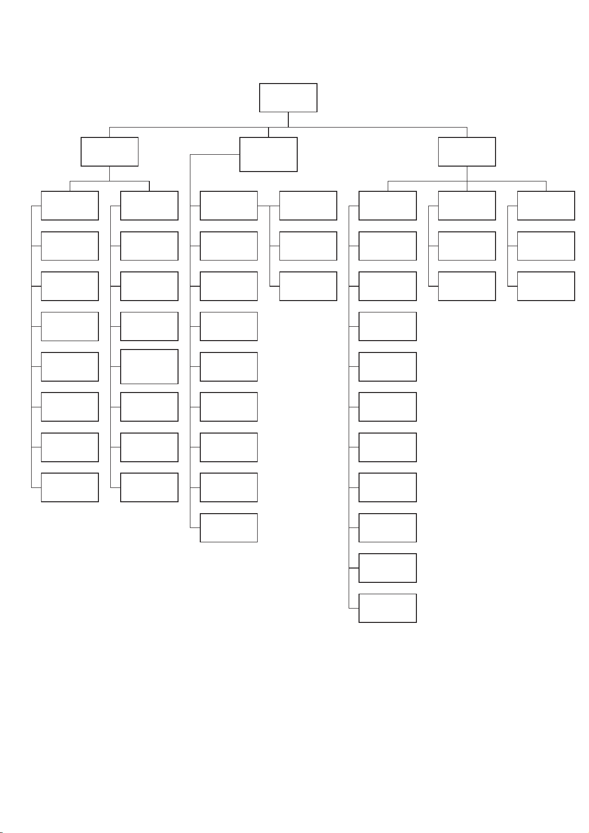
Air Conditioner Troubleshooting Chart
Page 20
NO COOLING OR
INSUFFICIENT
COOLING
CONTACTOR
OPEN
POWER SUPPLY
DEFECTIVE
LOW-VOLTAGE
TRANSFORMER
OPEN
THERMOSTAT
OPEN CONTROL
CIRCUIT
LOSS OF
CHARGE
COMPRESSOR
WILL NOT RUN
POWER SUPPLY
LOOSE LEADS AT
OPEN SHORTED
OR GROUNDED
CONTACTOR
CLOSED
COMPRESSOR
OPEN
COMPRESSOR
FAULTY START
GEAR (1-PH)
COMPRESSOR
MOTOR
WINDINGS
COMPRESSOR
STUCK
COMPRESSOR
OUTDOOR FAN
STOPPED OR
CYCLING ON
OVERLOAD
OUTDOOR AIR
RESTRICTED OR
RECIRCULATING
RESTRICTED
DISCHARGE
TUBE
OVERCHARGE
OR NON-
CONDENSABLES
IN SYSTEM
LOW
REFRIGERANT
CHARGE
LINE VOLTAGE
TOO HIGH OR
LOW
RUNS BUT
CYCLES ON
INTERNAL
OVERLOAD
LOOSE LEAD
AT FAN MOTOR
MOTOR
DEFECTIVE
INCORRECT
OFM
CAPACITOR
LOW SUCTION
PRESSURE
DIRTY AIR
FILTERS
DUCT
RESTRICTED
DAMPERS
PARTLY CLOSED
INDOOR COIL
FROSTED
SLIGHTLY
LOW ON
REFRIGERANT
COMPRESSOR
RUNS BUT
INSUFFICIENT
COOLING
HIGH SUCTION
LOW HEAD
PRESSURE
DEFECTIVE
COMPRESSOR
VALVES
INTERNAL
PRESSURE
RELIEF OPEN
HIGH SUCTION
LOW
SUPERHEAT
UNIT
OVERCHARGED
INCORRECT
SIZE
PISTON
CONTACTOR OR
COIL DEFECTIVE
LOOSE
ELECTRICAL
CONNECTION
COMPRESSOR
INTERNAL
PROTECTION
OPEN
DEFECTIVE RUN
CAPACITOR
DEFECTIVE RUN
CAPACITOR
COMPRESSOR
BEARINGS
HIGH
SUPERHEAT
LIQUID LINE
SLIGHTLY
RESTRICTED
PISTON
RESTRICTED
INCORRECT
SIZE
PISTON
INDOOR COIL
STRAINER
RESTRICTED
INDOOR
BLOWER MOTOR
DEFECTIVE OR
CYCLING ON OL
Page 21
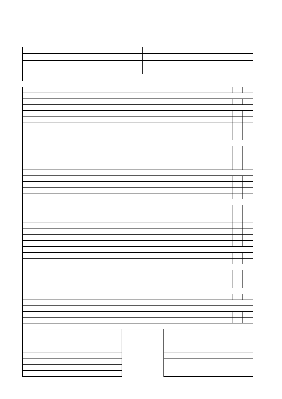
MANDATORY START-UP CHECK LIST AND RECORD
A copy of this checklist data has to be submitted to carrier representative. Completion of this checklist is a must for any field claim, no field support will be provided for
Page 21
IMPORTANT!
This page is a mandatory checklist & record – the check to be executed and data to be recorded for future reference incase of failure.
incomplete or blank checklists.
Preliminary Information
Outdoor Model Number:
Indoor Model Number:
Startup Date:
Customer Name/Address: Project Name:
Additional Accessories:
Outdoor Serial Number:
Indoor Serial Number:
Technician Name:
Pre-Start-Up Checklist
Outdoor Unit
Is there any shipping damage?
If the unit is damaged, Please specifiy where:
Will this damage prevent the unit start-up?
Check power supply to see if it matches the unit data plate?
Has the ground wire been properly connected?
Are the circuit protection matched with the unit size and installed properly?
Are the power wire guage matched with the unit size and installed properly?
Piping
Are both refrigerant lines flushed / cleaned, connected to service valve sets and properly tightend?
Are all the service valves open and backseated ?
Are the Stem Valves Installed and snug?
Have all the refrigerant connections and piping joints checked for leaks and vacuum test conducted to 500 micron?
Indoor Fan Coil Unit Piping
Check accurater device size is matched and installed in fan coil unit? (If Applicable)
TEAR ALONG THE DOTTED LINE
Are the refrigerant connections properly connected and have been checked for leakages?
Is condensate line connected?
Is the condensate line free from obstacle and drains freely?
Controls
Are control power lines connected to there control power terminal block?
Are terminal snug in the housing?
Are control power lines and control cables routed separately (Not in the same conduit and not in same multi-conductor cable?
Are control wires connected to the same circuit as associated refrigerant lines?
Check to make sure the subbase mounting to wall is secure? ( Don’t apply excessive force to mounting screw)
Are fresh batteries installed in the fan coil remote controller?
Does remote controller backlight illuminate when the button is pressed?
Fan System
Does fan rotate freely?
Are air filters in place and clean?
Indoor Power Supply
Does the power supply match the fan coil unit data plate?
Is ground wire connected?
Start-Up Checklist
Check Indoor Fan Operation Under Ceiling Fan Coil Units
Select fan mode, then initiate test sequence. Does the fan motor start at low speed , then shift to medium then to high?
Start System Operation at the Fan Coil Unit
Select cooling mode and adjust set point, it must be below current room temperature then observe unit operation.
Does compressor start (After Initial Time Delay) and Run?
Does outdoor fan run properly?
After atleast 15 minutes of running time, record all the information below:
Outdoor Unit
Unit Amps(L1/L2/L3)
Voltage (L1/L2/L3)
Vapor Line Pressure
Vapor Line Temp
Liquid Line Temp
Entering Outdoor Air Temp
Leaving Outdoor Air Temp
Indoor Entering Air dB(Dry Bulb) Temp
Indoor Leaving Air dB(Dry Bulb) Temp
Indoor Entering Air wB(Wet Bulb) Temp
Indoor Leaving Air wB(Wet Bulb) Temp
Technician Name, Signature and Date:
Yes No NA
Yes No NA
Fan Coil Unit
Page 22

NOTES
Page 22
Page 23
Appendix
Page 23
Long-Line Guideline.
(Single Stage Application For 38C Only)
A. Safety Considerations
Only trained service technicians familiar with standard service instructions and training materials should attempt installation, service,
and repair of these units. Improper installation, adjustment, alteration, service, maintenance, or use can cause explosion, fire, electrical
shock, or other conditions which may cause death, personal injury, or property damage. Consult a qualified installer, service agency, or
your distributor or branch for information or assistance. The qualified installer or agency must use factory - authorized kits or
accessories when modifying this product. Refer to the individual instructions packaged with the kits or accessories when installing.
Follow all safety codes. Wear safety glasses, protective clothing, and work gloves. Use quenching cloth for brazing operations. Have
fire extinguisher available. Read these instructions thoroughly and follow all warnings or cautions included in literature and attached to the
unit. Consult local building codes and National Electrical Code (NEC) for special requirements.
Recognize safety information. This is the safety- alert symbol . When you see this symbol on the unit and in instructions or
manuals, be alert to the potential for personal injury. Understand these signal words; DANGER, WARNING, and CAUTION. These
words are used with the safety- alert symbol. DANGER identifies the most serious hazards which will result in severe personal injury or
death. WARNING signifies hazards which could result in personal injury or death. CAUTION is used to identify unsafe practices
which may result in minor personal injury or product and property damage. NOTE is used to highlight suggestions which will result in
enhanced installation, reliability, or operation.
!
WARNING
ELECTRICAL SHOCK HAZARD
Failure to follow this warning could result in personal injury or death.
All equipment should be installed in accordance with accepted practices and unit Installation Instructions, and in compliance with all
national and local codes. Power should be turned off when servicing or repairing electrical components. Extreme caution should
be observed when troubleshooting electrical components with power on. Observe all warning notices posted on equipment and in
instructions or manuals.
!
WARNING
EXPLOSION AND PERSONAL SAFETY HAZARD
Failure to follow this warning could result in personal injury, equipment damage or improper operation.
Refrigeration systems contain refrigerant under pressure. Puron® refrigerant (R- 410A) systems operate at higher pressure than
standard R- 22 systems. Use only service equipment and components rated for Puron® refrigerant. Extreme caution should be
observed when handling refrigerants. Wear safety glasses and gloves to prevent personal injury. During normal system operations,
some components are hot and can cause burns. Rotating fan blades can cause personal injury. Appropriate safety considerations are
posted throughout this manual where potentially dangerous techniques are addressed.
Refrigeration systems contain refrigerant under pressure. Extreme caution should be observed when handling refrigerants. Wear safety
glasses and gloves to prevent personal injury. During normal system operations, some components are hot and can cause burns.
Rotating fan blades can cause personal injury. Appropriate safety considerations are posted throughout this manual where potentially
dangerous techniques are addressed.
B. Definitions
This Guideline c overs all residential split system air conditioner and heat pump products using Puron® refrigerant.
Page 24
C. Introduction
Page 24
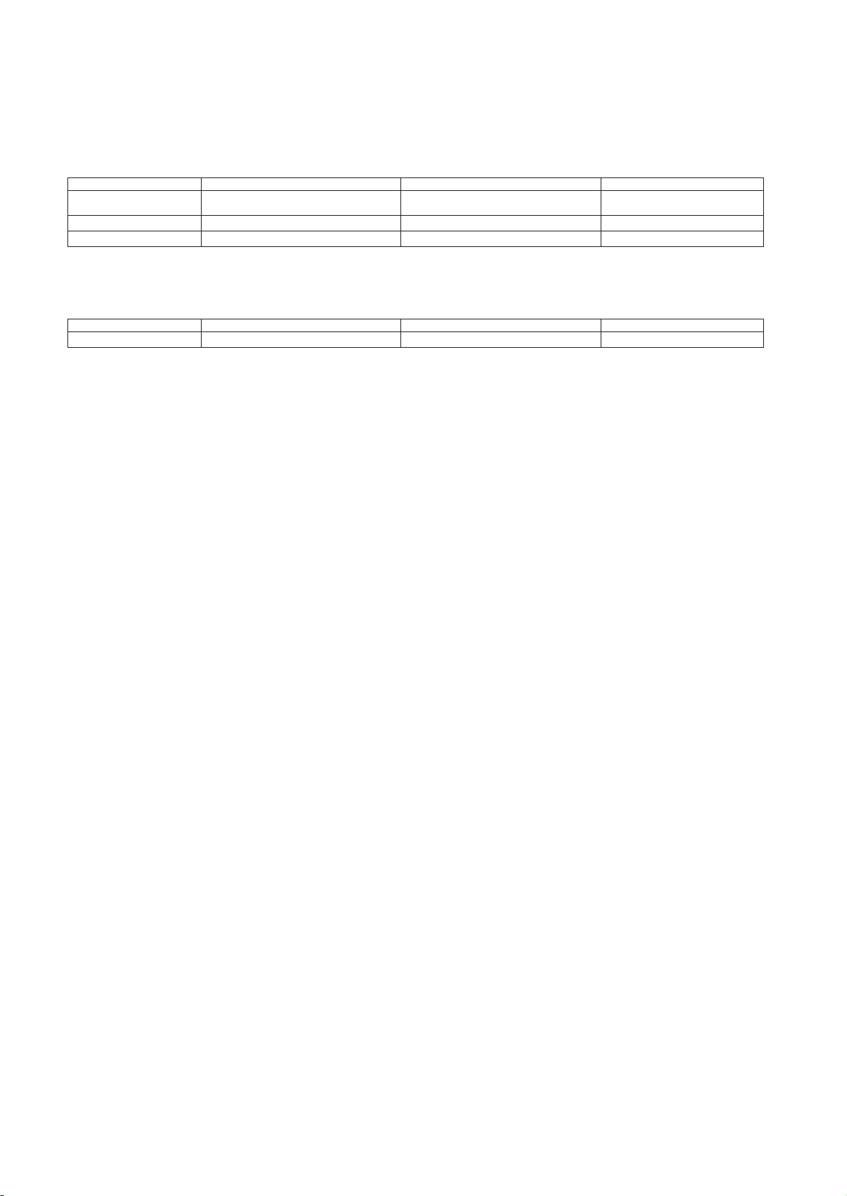
An application is considered Long Line, when the refrigerant level in the system requires the use of accessories to maintain acceptable
refrigerant management for systems reliability. See Table 1 for required accessories. Defining a system as long line depends on the
liquid line diameter, actual length of the tubing, and vertical separation between the indoor and outdoor units.
For Air Conditioner systems, the chart below shows when an application is considered Long Line.
AC WITH PURON® REFRIGERANT LONG LINE DESCRIPTION ft (m)
Liquid Line
Size
Units On Same Level Outdoor Below
1/4
5/16
120 (36.6) 50 (15.2) vertical or 120 (36.6) total 120 (36.6)
3/8
80 (24.4) 35 (10.7) vertical or 80 (24.4) total 80 (24.4)
No accessories needed within
For Heat Pump systems, the chart below shows when an application is considered Long Line.
HP WITH PURON® REFRIGERANT LONG LINE DESCRIPTION ft (m)
Liquid Line
Size
Units On Same Level Outdoor Below
3/8
80 (24.4) 20 (6.1) vertical or 80 (24.4) total 80 (24.4)
Long line applications are clearly defined in this Guideline, and must be treated differently from standard systems. A long line system
requires special consideration for the following reasons:
• Additional refrigerant charge
• Refrigerant migration control
• Oil return concerns
• Capacity losses
• Metering device adjustments
Longer line sets require additional refrigerant charge that must be managed throughout the entire range of possible ambient conditions.
Off- cycle refrigerant migration that results in excess refrigerant in the compressor at start up, or condensed liquid refrigerant in the
suction line at startup must be avoided for compressor reliability. Follow all accessory requirements in this Guideline to control offcycle refrigerant migration (see Table 1).
Another concern is proper line set sizing and construction to control oil return to the compressor, and minimize capacity losses. In
residential applications, proper suction line sizing is critical to achieve adequate oil return, and maintain expected system performance. Oil
return in heating mode is different from cooling mode thus, in some cases; heat pumps have additional line set limitations from air
conditioning units. Table 3 in this guideline can be used to properly size suction lines. Follow all suction line sizing recommendations to
ensure system performance and adequate oil return for compressor lubrication.
The third
concern is refrigerant metering. Elevation changes affect pressure drop in refrigerant lines. These effects must be considered
when sizing liquid lines and orifice- metering devices. Since all current products utilize a TXV for cooling mode metering, piston
sizing is only a concern for heat pump heating operation. Follow piston change recommendations in this Guideline for proper heat
pump heating operation (see Tables 9 & 12).
Since the last revision of this guideline, testing has been done to determine limitations for the application of 1/4 and 5/16 inch liquid
lines in cooling only systems. The limiting factor when sizing liquid lines is pressure drop. Equivalent length and vertical separation
both contribute to the pressure drop in a liquid line. The liquid line sizing charts in this guideline have been developed based on a TXV
metering device on the indoor coil. Staying within these guidelines and charging to a minimum of 10°F (5.6°C) subcooling will ensure a
column of liquid is present at the TXV. There is no capacity of efficiency changes to the system performance when staying within these
guidelines.
NOTE:
When an application is “Long Line” the accessories shown in Table 1 are required. D.
General Limitations
Liquid Lines - AC Only
Liquid line diameters of 1/4” and 5/16” and 3/8” are allowed for cooling only systems and limitations are provided. Using smaller
liquid lines affects the maximum allowable equivalent length and when the application qualifies as long line. Elevation changes
between the indoor and outdoor units also affect allowable equivalent lengths. See tables 5, 7, and 10 to properly size liquid lines.
NOTE: Using 1/4 and 5/16” liquid lines within the limits provided, result in no capacity or efficiency changes to the system.
Liquid Lines - Heat Pump
Liquid line sizing for heat pumps is currently limited to 3/8”. Future updates are planned to include alternate liquid line sizing for heat
pump applications. Check HVAC Partners for updates.
Suction Lines
Table 3 to properly size suction lines. Acceptable suction line sizes are shown for each size and type system. Air conditioners and
Use
heat pumps have separate charts due to oil return needs for heat pumps in heating mode.
Beyond these lengths, long line accessories are required
Indoor
Outdoor Above In
allowed
length
allowed
s
No accessories needed within
length
s
Beyond these lengths, long line accessories are required
Indoor
Outdoor Above In
175 (53.3)
door
door
Page 25
90° Std (A)
90° Long
---
Rad (B)
45° Std (C)
1/2
5/8 1.6
1.0
0.8
3/4
7/8 2.0
1.4
1.0
1 --- 1/8
Liquid Line Solenoid
12
Filter Drier
6
Page 25
A
CCESS
Liquid l
solenoid
at ou
TXV on indoor (Standard
on all 13 SEER
indoor coils
and fan
Crankcase h
(if not factory su
Start capacitor and r
Heating piston
Inverted trap
ORY
ine
(LLS)
tdoor
coils)
platfo
eater
pplied)
elay
change
rm
Table 1 – Long Line Accessory Requirements
OUTDOOR UNIT
AC
No
Ye
s
Ye
s
Ye
s
N/A
N/A
ABOVE OUTDOOR UNIT BELOW NO ELEVATION
HP
Ye
s
KHALS0401LLS
Ye
s
Ye
s
Ye
s
Yes
T
able
see
N/A
AC
No
Ye
Ye
Ye
12
N/A
Ye
See Fig. 3
s
s
s
s
HP
Ye
s
KHALS0401LLS
Ye
s
Ye
s
Ye
s
Ye
s
see Table 9
Ye
s
See Fig. 3
AC
No
Ye
Ye
Ye
N/A
N/A
s
s
s
CHAN
GE
HP
Ye
s
KHALS0401LLS
Ye
s
Ye
s
Ye
s
No
N/A
!
CAUTION
COMPONENT FAILURE HAZARD
Failure to follow this caution may result in unit component failure.
For proper oil return and minimizing capacity losses, only use vapor line sizes listed in Tables 3.
E. Interconnecting Tubing and Fitting Losses
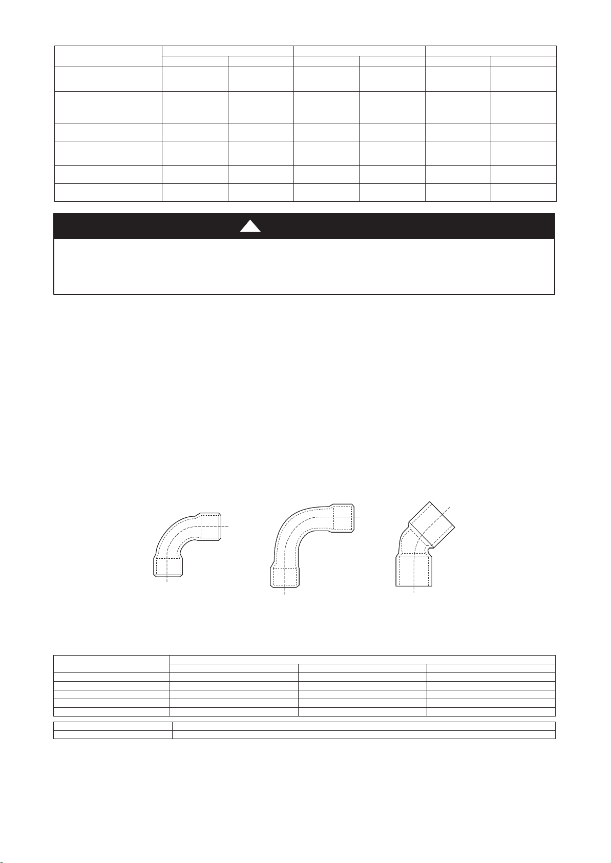
Choosing the proper tubing diameters is critical for reliable long line applications. For proper suction line sizing, see Table 3 the chart
shows all acceptable suction line diameters and related performance data based on total equivalent length. See Tables 5, 7, and 10 for
the allowable liquid tubing diameters for single- stage.
Refrigerant tubing must be measured both in terms of actual length and equivalent length. Use actual length for limitations and
refrigerant charge calculation. The maximum liquid line length will vary depending on diameter and elevation change between indoor
and outdoor units. Equivalent length takes into account pressure losses from both tubing length and losses due to fittings and
accessories, such as elbows, liquid line solenoid and filter drier. Losses from fittings are expressed in equivalent length, meaning the
length of straight tubing that would have the same pressure loss as the fitting. See Table 2 for equivalent lengths of commonly used
fittings and accessories; maximum equivalent length allowed is up to See Table 5, 7 , and 10for maximum total equivalent length.
Calculate
total equivalent length by adding linear (actual) length of the tubing required and the equivalent length of all elbows and
accessories used. See Tables 3 to determine capacity loss of the system due to equivalent length losses and subtract them from the
published system capacity for the particular outdoor/indoor unit combination. This data is found in the outdoor unit Product Data.
Example: A 4- ton system using 7/8 in. diameter line set has a total tubing length of 165 ft. The tubing configuration uses four standard
90° elbows and two 90° long- radius elbows. Checking Table 2, the total equivalent length is calculated as:
165 ft straight tubing + (four standard 90° elbows x 2 ft) + (two long- radius 90° elbows x 1.4 ft) = 165 ft. + 8 ft + 2.8 ft = 175.8 ft total
equivalent length.
A
B
C
90° STD
90° LONG RAD
Fig. 1 – Tube Bend Losses
45° STD
A01058
Tube Size O.D. (In.)
1.2 0.8 0.6
Table 2 – Fitting Losses in Equivalent Feet
Fitting --- Reference Diagram in Fig.
1
1.8 1.2 0.9
2.6 1.7 1.3
Page 26
F. Metering Device — Long Line Cooling
Page 26
In current equipment, all indoor units use a TXV with 15 to 30% bleed for metering in the cooling mode. This provides adequate
refrigerant migration protection for all cooling applications.
G. Piston Sizing — Heat Pumps Only
An AccuRater
the factory- supplied AccuRater
TM
(fixed orifice) is used for refrigerant metering in the heating mode. This fixed expansion device must be changed from
TM
based on indoor/outdoor vertical separation and system capacity. For horizontal applications up to
200 ft (61 m) linear length and 250 ft (76 m) total equivalent length, no heating piston change is necessary.
When sizing the heating piston for installations where the outdoor unit is below the indoor unit, use Table 9. When outdoor unit is
located above indoor unit, use Table 12.
Example: The
equivalent ft of line set. Approximately 60 ft (18.3 m) is horizontal and the outdoor unit is 140 ft (42.7 m) above the indoor unit. Table
9 shows the AccuRater
factory supplied AccuRaterTM for a single- stage 3- ton heat pump is a number 57. A system is installed with 200
TM
piston change to be +6. The new piston size is 57 + 6 = 63. If a 63 is not produced, round up to the next
larger available piston size.
On the same heat pump, if the outdoor unit was located 49 ft (14.9 m) below the indoor unit, Table 10 shows the piston change to be 57
- 2 = 55. If a 55 piston is not produced, round up to the next available size.
H. Liquid Line Solenoid — Long Line Heat Pump Heating
Since
AccuRaterTM do not provide off- cycle refrigerant migration protection in the heating mode, a liquid line solenoid is required for
single-stage and two- stage heat pump long line applications. Bi-flow solenoid valves provide flow control protection only in the
direction of the arrow molded into the valve. The arrow must point toward the outdoor unit for off- cycle refrigerant control in the
heating mode. The arrow shows the direction of flow control. The solenoid should be installed within 2 ft. of the outdoor unit. The
liquid line solenoid kit number for a heat pump is KHALS0401LLS.
NOTE: Equivalent length of the liquid line solenoid should be added to the total equivalent length of the tubing. See Table 2.
I. Charging Information
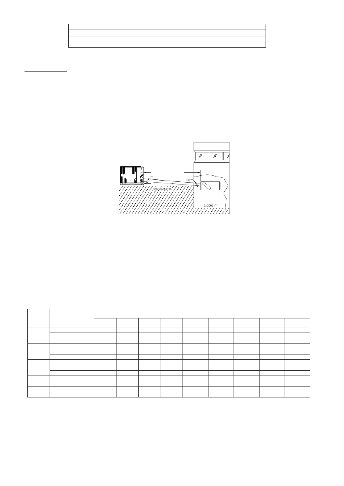
Use subcooling as the primary method for charging longline applications. Outdoor units are pre- charged for 15 ft (4.6 m) of 3/8 liquid
line. When using different length diameter liquid lines, charge adjustments are required. See Table 4 for charge adjustments required.
The charge adjustment will depend on the liquid line diameter used. See unit installation instructions for proper charging procedure.
For all long line applications, pressure drop and subcooling loss become a concern. In these applications, a minimum of 10°F (5.6°C) of
subcooling is required for all liquid line diameters to ensure no refrigerant flashing occurs before the TXV metering device.
Systems should be charged to 10°_ subcooling or the rating plate subcooling, whichever is greater.
The amount of factory- charge can be found on the unit rating plate or in the Product Data literature. Long line applications do not
require additional oil charge.
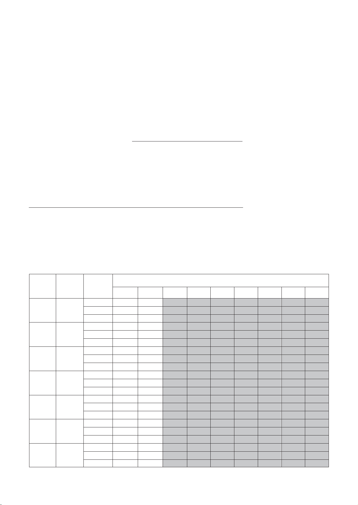
VAPOR LINE SIZING AND COOLING CAPACITY LOSS
Acceptable vapor line diameters provide adequate oil return to the compressor while avoiding excessive capacity loss. The suction line
diameter shown in Table 3 is acceptable for AC and HP systems with Puron refrigerant:
Table 3 - Vapor Line Sizing and Cooling Capacity Losses — Puron® Refrigerant 1- Stage Air Conditioner Applications
o
151
(46.0
ictions.
(m)
tal
--- 175
--- 53.3)
176
--- 200
201
--- 225
(53.6
--- 61.0)
(61.3
--- 68.6)
226
(68.9
No
Size
18000
1
AC with
Puron
24000
1
AC with
Puron
30000
1
AC with
Puron
36000
1
AC with
Puron
42000
1
AC with
Puron
48000
1
AC with
Puron
60000
1
AC with
Puron
Unit
minal
(Btuh)
Stage
Stage
Stage
Stage
Stage
Stage
Stage
Maximum
Liquid Line
Diameters
(In. OD)
3/8
3/8
3/8
3/8
3/8
3/8
3/8
Line
Vapor
Diameters
(In. OD)
1/2
1 2 3 5 6 7 8 9 11
5/8
0 1 1 1 2 2 2 3 3
3/4
0 0 0 0 1 1 1 1 1
5/8
0 1 2 2 3 3 4 5 5
3/4
0 0 1 1 1 1 1 2 2
7/8
0 0 0 0 0 1 1 1 1
5/8
1 2 3 3 4 5 6 7 8
3/4
0 0 1 1 1 2 2 2 3
7/8
0 0 0 0 1 1 1 1 1
5/8
1 2 4 5 6 8 9 10 12
3/4
0 1 1 2 2 3 3 4 4
7/8
0 0 0 1 1 1 1 2 2
3/4
0 1 2 2 3 4 4 5 6
7/8
0 0 1 1 1 2 2 2 3
1
1/8
0 0 0 0 0 0 0 0 0
3/4
0 1 2 3 4 5 5 6 7
7/8
0 0 1 1 2 2 2 3 3
1
1/8
0 0 0 0 0 0 0 1 1
3/4
1 2 4 5 6 7 9 10 11
7/8
0 1 2 2 3 4 4 5 5
1
1/8
0 0 0 1 1 1 1 1 1
26
--- 50
(7.9
--- 15.2)
Applications in this
(15.5
51
--- 80
--- 24.4)
area may be
81
(24.7
long line and
Cooling Capacity Loss (%) T
Equivalent Line Length ft.
--- 100
101
--- 125
--- 30.5)
(30.8
--- 38.1)
may h
ave height restr
126
(38.4
--- 150
--- 45.7)
--- 250
--- 76.2)
Page 27
Page 27
Liquid Line
Table 4 - Refrigerant Charge Adjustments
Size
Puron Charge
(oz/ft)
3/8 0.60 (Factory charge for lineset = 13.5 oz (382.7)
5/16
0.40
1/4
0.27
Units are factory charged for 25 ft (7.6 m) of 3/8” liquid line. The factory charge for 3/8” lineset 9 oz (266.2 g). When using other length or
diameter liquid lines, charge adjustments are required per the chart above.
Charging Formula:
[(Lineset oz/ft x total length) – (factory charge for lineset)] = charge adjustment
Example 1: System has 25ft of line set using existing 1/4“liquid line. What charge adjustment is required?
Formula: (.27 oz/ft x 25ft) – (13.5 oz) = -6.75 oz; (8.0 g/m x 7.6 m) – (382.7 g) = -321.9 g
Net result is to remove 6.75 oz of refrigerant from the system
Example 2: System has 45 ft of existing 5/16” liquid line. What is the charge adjustment?
Formula: (.40 oz/ft. x 45ft) – (13.5 oz.) = 9 oz; (11.8 g/m x 13.7m) – (382.7 g) = -221.0 g
Net result is to add 4.5 oz of refrigerant to the system
Fig. 2 – Equal– Level Outdoor/Indoor Unit
• A TXV with 15 to 30% bleed must be installed at indoor unit when application qualifies as long line. See Table 6.
• Hard Start Kit (start capacitor and relay) must be installed on outdoor unit when application qualifies as long line. See Table 6.
• A crankcase heater must be installed on compressor when the application qualifies as long line. See Table 6 .
• Vapor line should slope towards indoor unit.
• Maximum actual liquid line is up to 100 (61 m). See Table 5.
• Maximum total equivalent length is up to 120 (76.2 m). See Table 5.
• Heat pump only – Bi- flow liquid line solenoid must be installed within 2 ft (0.61 m) of outdoor unit with arrow pointing towards
outdoor unit.
•
Heat pump only – Outdoor AccuRater
TM
adjustment not required
• Use vapor line per Tables 3.
• Use liquid lines per Table 5.
Table 5 – Maximum Total Equivalent Length
Size
18000
24000
30000
36000
48000
60000
*
Maximum actual length not to exceed 100ft
**
Total equivalent length accounts for losses due to elbows or fitting. See the Table 2 for details.
=
outside acceptable range
--- ---
System
AC
AC
AC/HP
AC
AC
AC/HP
AC
AC
AC/HP
AC
AC/HP
AC/HP
AC/HP
Diameter
Ty
pe
Only 1/4
Only 5/16
Only 1/4
Only 5/16
Only 1/4
Only 5/16
Only 5/16
Liquid
Line
w/ TXV
3/8
75 75 75 50 50 ---
3/8
30 ---
3/8
3//8
3/8
3/8
0 --- 5
(0 --- 1.5)
150*
150*
150*
150*
150*
150*
150*
150*
150*
150*
150*
Equal Level or Outdoor Unit Below Indoor
6 --- 10
(1.8
--- 3.0)
150*
125 100 100 75 ---
150*
150*
150*
150*
---
---
125*
100 150 125 100 75 ---
150*
150*
150*
150*
150*
LSV (Heat Pump
Only)
Maximum Total Equivalent L
--- 20
11
(3.4
--- 6.1)
150*
150*
150*
150*
---
---
150*
150*
100 100 100 75 ---
150*
150*
150*
(6.4
21
150*
150*
150*
150*
150*
150*
150*
150*
--- 30
--- 9.1)
---
---
eng
Vertical Sepa ration ft
th**: Outdoor unit BELOW In
--- 40
31
(9.4
--- 12.2)
150*
150*
150*
150*
---
---
150*
150*
150*
150*
(12.5
(m)
41
150*
150*
150*
150*
150*
150*
150*
150*
--- 15.2)
--- 50
(15.5
---
---
---
---
51
--- 18.3)
150*
150*
150*
150*
150*
150*
150*
150*
door
--- 60
---
---
---
---
125 100
---
---
---
(18.6
61
--- 21.3)
150*
150*
150*
150*
150*
150*
--- 70
(21.6
---
---
150
---
---
---
---
---
---
---
---
---
---
---
71
--- 24.4)
150*
150*
150*
150*
--- 80
---
---
---
---
---
---
---
Page 28
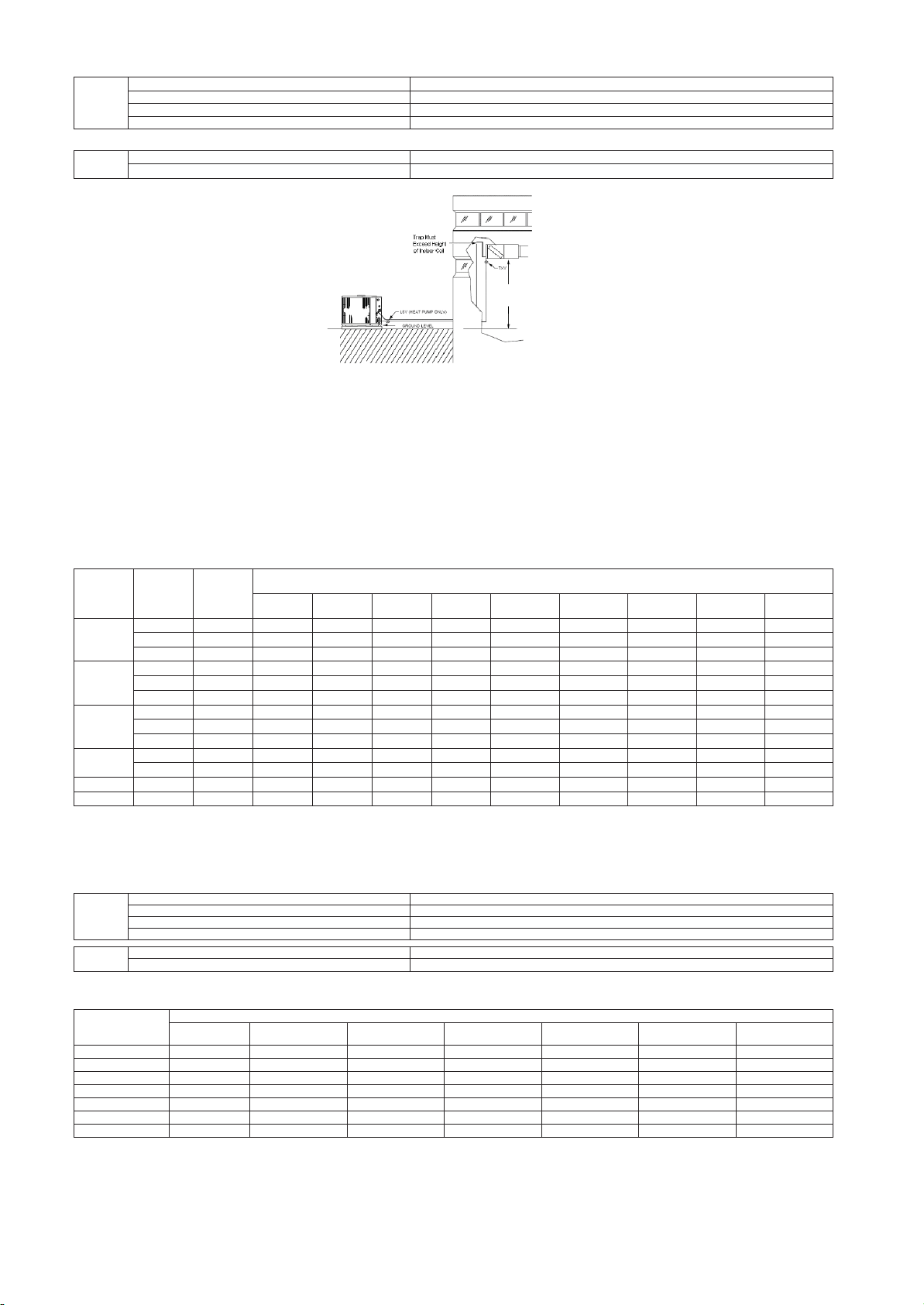
AC
3/8
80 (24.4)
HP Liquid Line
Size
Units On Same Level
5/16 50 (15.2) vertical or 120 (36.6) total
60,000 0 ---
1
---
2
---
3
---
3 — —
Page 28
Table 6 – AC / HP with Puron® Refrigerant Long Line Description ft (m)
Beyond these lengths, long line accessories are required
AC Liquid Line
1/4
No accessories needed within allowed
5/16
120 (36.6)
Size
Units On Same Level
lengths
HP
3/8
80 (24.4)
See Table 8 for
Maximum
Height and
Equivalent
Length
Fig. 3 – Outdoor Unit Below Indoor Unit
• Unit must be charged to 10° subcooling or nameplate subcooling, whichever is greater.
• A TXV with 15 to 30% bleed must be installed at indoor unit when application qualifies as long line. See Table 8.
• A crankcase heater must be installed on compressor when the application qualifies as long line. See Table 8.
• Hard Start Kit (start capacitor and relay) must be installed in outdoor unit when the application qualifies as long line. See Table 8.
• An inverted vapor- line trap must be installed at indoor unit. The top peak of trap must be greater than height of indoor coil.
• Ma
ximum actual liquid line length is up to See Table 7 for maximum total equivalent length.
• Heat pump only – Bi- flow liquid line solenoid must be installed within 2 ft (0.61 m) of outdoor unit with arrow pointing towards outdoor unit.
• Heat pump only – Adjust outdoor piston per Table 9.
• Use vapor line per Tables 3.
• Use liquid lines per Table 7.
Table 7 - Maximum Total Equivalent Length**
System
Size
Ty
pe
18000
24000
30000
36000
48000
60000
*
Maximum actual length not to exceed 100ft
**
Total equivalent length accounts for losses due to elbows or fitting. See the Table 2 for details.
=
--- ---
AC Only
AC Only
AC/HP
AC Only
AC Only
AC/HP
AC Only
AC Only
AC/HP
AC Only
AC/HP
AC/HP
AC/HP
outside acceptable range
Liquid
Line
Diameter
w/ TXV
1/4
150 150 125 100 100 75 ---
5/16
3/8
1/4
75 75 75 50 50 ---
5/16
3/8
1/4
30 ---
5/16
3/8
150* 150* 150* 150* 150* 150* 150* 150* 150*
5/16
3//8
150* 150* 150* 150* 150* 150* 150* 150* 150*
3/8
3/8
0 --- 5
(0 --- 1.5)
150*
150*
150*
150*
150*
150* 150* 150* 100 100 100 75 ---
150*
150*
Outdoor Unit Below Indoor Unit
Maximum Total Equivalent L
(1.8
6 --- 10
--- 3.0)
150*
150*
150*
150*
150*
150*
150*
---
---
(3.4
11
150*
150*
150*
150*
150*
150*
150*
--- 6.1)
--- 20
---
---
(6.4
21
150*
150*
150*
150*
150*
150*
150*
ength{: Outdoor unit BELOW In
Vertical Sepa ration ft
--- 30
--- 9.1)
---
---
125 100 75 ---
(9.4
--- 40
31
--- 12.2)
150*
150*
150*
150*
---
150*
150*
---
(m)
--- 50
41
(12.5
--- 15.2)
150*
150*
---
---
150*
150* 125 100
150*
---
---
150*
150*
110 ---
Table 8 - AC / HP with Puron® Refrigerant Long Line Description ft (m)
AC Liquid Line
AC
HP
1/4
3/8
HP L iquid Line
3/8
Beyond these lengths, long line accessories are required
Size
Outdoor Below In
No accessories needed within allowed
35 (10.7) vertica l or 80 (24.4) total
Size
Outdoor Below In
20 (6.1) ve rtical or 80 (24.4) total
Table 9 - Puron®
Btuh
18,000 0
24,000 0
30,000 0
36,000 0
42,000 0
48,000 0
0 --- 19
(0
--- 5.8)
NOTE: (—) Indicates vertical separation exceeds allowable
Example 1: On a 4 ton system the outdoor unit is 60 ft (18.3 m) below the indoor unit. This is acceptable onl y if the total equivalent length is 230 ft (70.1 m)
The heating piston must be re
Example 2: On a 3
heating piston must be re
---
ton system the outdoor unit is 80 ft (24.4 m) below the indoor u nit. This is acceptable up to 250 ft (76.2 m) total equivalent length. The
---
Refrigerant Heat Pump Outdoor Piston Change – Outdoor Unit BELOW Indoor Unit
Vertical Separation ft (m) --- Outdoor BELOW Indoor
(12.2
--- 49
40
--- 14.9)
---
2
---
2
---
2
---
2
---
2
---
2
(15.2
--- 59
50
--- 18.0)
---
2
---
2
---
2
---
2
---
3
---
3
---
sized
sized
---
3.
--- 29
20
(6.1
--- 8.8)
---
1
---
1
---
1
---
1
---
1
---
1
---
3.
limits.
(9.1
30
--- 11.9)
---
---
---
---
---
---
--- 39
1
1
1
2
2
2
(15.5
door
51
150*
150*
150*
150*
door
door
--- 18.3)
--- 60
(18.6
---
---
---
---
---
---
lengths
U
--- 69
60
(18.3
--- 21.0)
---
2
---
3
---
3
---
3
---
3
---
3
--- 70
61
--- 21.3)
---
---
150*
150*
150*
---
---
150*
---
---
---
---
---
---
150*
---
---
---
nit)
(21.6
(21.3
70
--- 24.4)
---
2
---
3
---
3
---
3
---
4
—
71
--- 24.4)
150*
150*
--- 80
--- 80
---
---
---
---
---
---
---
o
r less.
Page 29
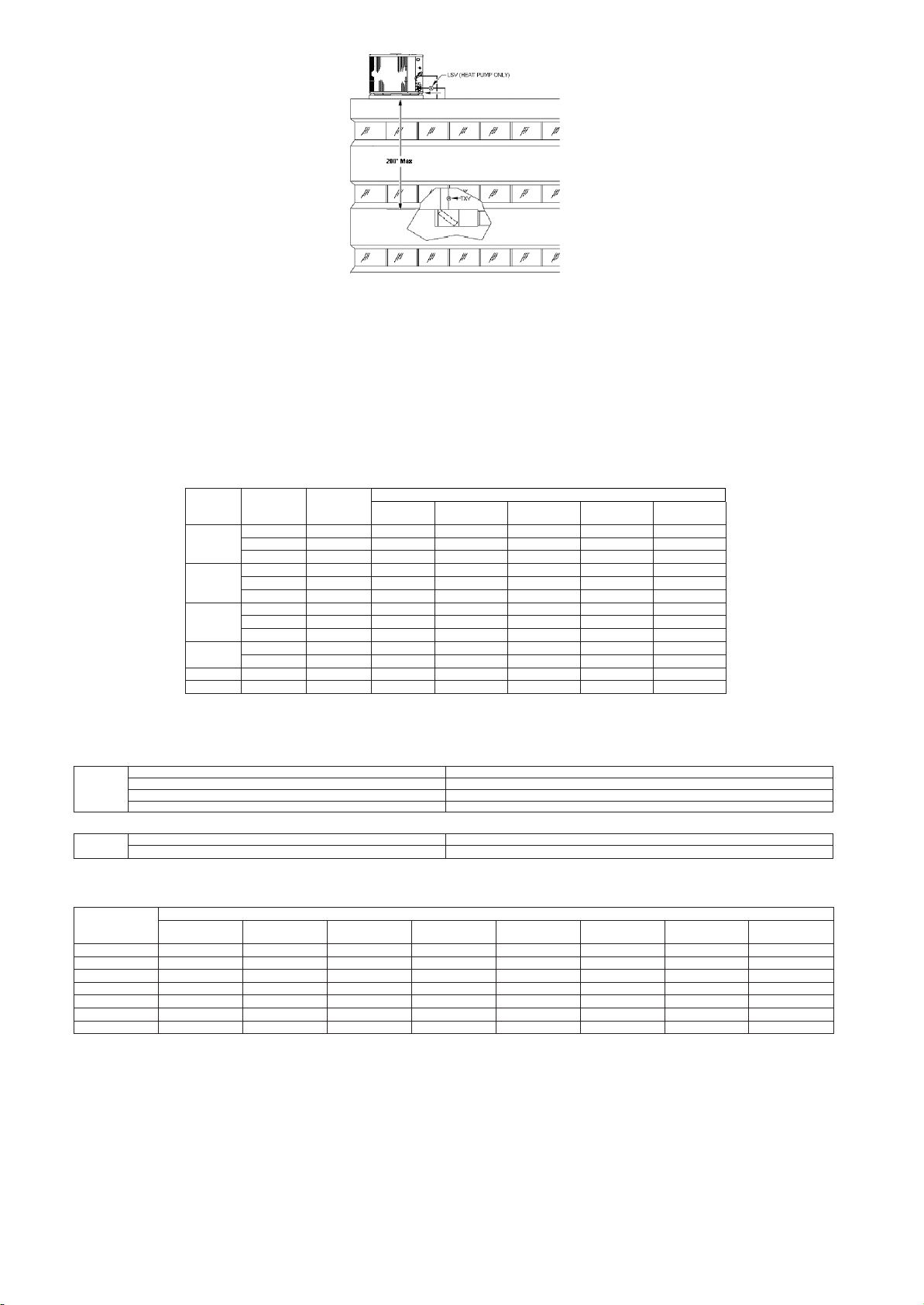
Vertical Separation ft ( m) Outdoor unit ABOVE indoor unit
Page 29
Fig. 4 – Outdoor Unit Above Indoor Unit
• A TXV with 15 to 30% bleed must be installed at indoor unit when the application qualifies as long line. See Table 11.
• A crankcase heater must be installed on compressor when the application qualifies as long line. See Table 11.
• Hard Start Kit (start capacitor and relay) must be installed in outdoor unit when the application qualifies as long line. See Table 11.
• Heat pump only – Heating piston must be changed as shown in Table 12.
• Maximum actual liquid line length is up to 200 ft (61 m). See Table 10.
• Maximum total equivalent length is up to 250 ft (61 m). See Table 10.
• Heat p
ump only – Bi- flow liquid line solenoid must be installed within 2 ft (0.61 m) of outdoor unit with arrow pointing towards outdoor unit.
• Use vapor line sizes per Tables 3.
• Use liquid lines per Table 10.
• Vapor line traps are not required.
*Maximum Actual Length Not to Exceed 200ft (61 m)
AC
Table 10 - Puron Refrigerant Maximum Total Equivalent Length Outdoor Unit ABOVE Indoor Unit
Size
18000
24000
30000
36000
48000
60000
System
Ty
AC
Only
AC Only
AC/HP
AC Only
AC Only
AC/HP
AC Only
AC Only
AC/HP
AC Only
AC/HP
AC/HP
AC/HP
Liquid
Line
pe
Diameter
1/4
150* 150* 150* 150 * 150*
5/16
150* 150* 150* 150 * 150*
3/8
150* 150* 150* 150 * 150*
1/4
100 125 150* 150* 150*
5/16
150* 150* 150* 150 * 150*
3/8
150* 150* 150* 150 * 150*
1/4
30 ---
5/16
150* 150* 150* 150 * 150*
3/8
150* 150* 150* 150 * 150*
5/16
150* 150* 150* 150 * 150*
3/8
150* 150* 150* 150 * 150*
3/8
3/8
25
(7.6)
150*
150*
--- 50
26
(7.9
--- 15.2)
---
---
150* 150 * 150 * 150*
150* 150 * 150 * 150*
(15.5
--- 75
51
--- 22.9)
---
76
(23.2
---
--- 100
--- 30.5)
---
---
101
(30.8
--- 125
--- 38.1)
---
Table 11 - AC / HP with Puron® Refrigerant Long Line Description ft (m)
Beyond these lengths, long line accessories are required
AC Liquid Line
Size
Outdoor Above In
1/4
175
5/16
120
3/8
80
(53.3)
(36.6)
(24.4)
door
HP
AC Liquid Line
Btuh
18,000
24,000
30,000
36,000
42,000
48,000
60,000
Table 12 - Heat Pump Outdoor Piston Change - Outdoor Unit ABOVE Indoor Unit
20
--- 25
(6.1
--- 7.6)
+1
+1
+1
+1
+1
+1
+1
Size
Outdoor Above In
3/8
80
Vertical Separation ft (m) --- Outdoor Above Indoor
--- 100
--- 30.5)
+3
+3
+4
+4
+4
+4
+5
101
(30.8
--- 125
--- 38.1)
+3
+4
+5
+5
+5
+5
+6
(7.9
26
--- 50
--- 15.2)
+1
+1
+2
+2
+2
+2
+2
(15.5
51
--- 75
--- 22.9)
+2
+2
+2
+2
+3
+3
+3
(23.2
76
126
(38.4
--- 150
--- 45.7)
+4
+5
+6
+6
+7
+7
+8
(24.4)
door
151
(46.0
U
--- 175
--- 53.3)
+5
+6
+8
+8
+8
+9
+10
nit
176
--- 200
(53.6
--- 61.0)
+6
+7
+9
+9
+10
+10
+12
Page 30
J. General Requirements (Check List)
042
073
106
043
076
109
059
088
128
061
090
Page 30
All Long Line Applications
• TXV with 15 to 30% bleed must be installed at indoor unit.
• Hard Start Kit (start capacitor and relay) must be installed on outdoor unit.
• Crankcase heater must be installed on compressor.
• Use liquid line per Tables 5, 7, and 10.
• Use only vapor line sizes listed in Tables 3.
• Adjust charge per Table 4.
• Charge syst em to 10° subcooling or rating plate subcooling, whichever is greater.
Heat Pumps Only
• Bi- flow liquid line solenoid must be installed within 2 ft (0.61 m)of outdoor unit with arrow pointing towards outdoor unit.
Equal- level Outdoor/Indoor unit
• Outdoor unit and indoor unit must be within +/- 20 ft (6.1 m) vertical separation.
• Vapor line shou
Heat Pumps Only
• No outdoor AccuRater
ld slope towards indoor unit.
TM
adjustment required with less than 20 ft (6.1 m) vertical separation.
Outdoor unit BELOW indoor unit
• See Tables 6, 8, and 11 for longline thresholds.
• An inverted vapor- line trap must be installed at indoor unit. The top peak of trap must be greater than height of indoor coil. See
Fig. 3.
• Vertical separation and line set equivalent length must not exceed requirements listed in Tables 5, 7, or 10.
Heat Pumps Only
• Adjust outdoor AccuRater
TM
per Table 9 .
Outdoor unit ABOVE indoor unit
• Maximum vertical separation is 200 ft (61 m)
• Maximum actual line length is 200 ft (61 m)
• Maximum total equivalent length is 250 ft (76.2 m). See Table 10.
• Vapor line traps
Heat Pumps Only
• Adjust outdoor AccuRater
are not required.
TM
per Table 12.
Table 13 - Common AccuRaterTM – Piston Sizes Available through RCD
(Part numbers are all EA52PHxxx. The last 3 digits represent size.)
EA52PH032
035 065 096
037 067 098
038 068 101
040 070 104
063
093
046 078 110
049 080 113
052 082 116
055 084 120
057 086 125
Page 31

Page 31
Page 32
Page 32
Manufacturer reserves the rights to discontinue or change at any time, specifications or designs without notice and without incurring any obligations.
Supersedes Version: 38C-50Hz-IOM-01 Catalog Number: 38C-50-EN-IOM-02
Effective Date: 12-07-2017 Phase: 50Hz
 Loading...