

Page 1
Model Specific Instructions
NOTE: Read the entire instruction manual before starting the
installation. Refer to Split-System Air Conditioner Common
Installation and Start-Up Practices (included in this packet).
38CKB(N), 38CMB, 38BRB
Split-System Air Conditioner
SAFETY CONSIDERATIONS
Improper installation, adjustment, alteration, service, maintenance,
or use can cause explosion, fire, electrical shock, or other
conditions which may cause death, personal injury, or property
damage. Consult a qualified installer, service agency, or your
distributor or branch for information or assistance. The qualified
installer or agency must use factory-authorized kits or accessories
when modifying this product. Refer to the individual instructions
packaged with the kits or accessories when installing.
Follow all safety codes. Wear safety glasses, protective clothing,
and work gloves. Use quenching cloth for brazing operations.
Have fire extinguisher available. Read these instructions thoroughly and follow all warnings or cautions included in literature
and attached to the unit. Consult local building codes and National
Electrical Code (NEC) for special requirements.
Recognize safety information. This is the safety-alert symbol
When you see this symbol on the unit and in instructions or
manuals, be alert to the potential for personal injury.
Understand the signal word DANGER, WARNING, or CAUTION. These words are used with the safety-alert symbol. DANGER identifies the most serious hazards which willresultinsevere
personal injury or death. WARNING signifies hazards which
could result in personal injury or death. CAUTION is used to
identify unsafe practices which would result in minor personal
injury or product and property damage.
C
3
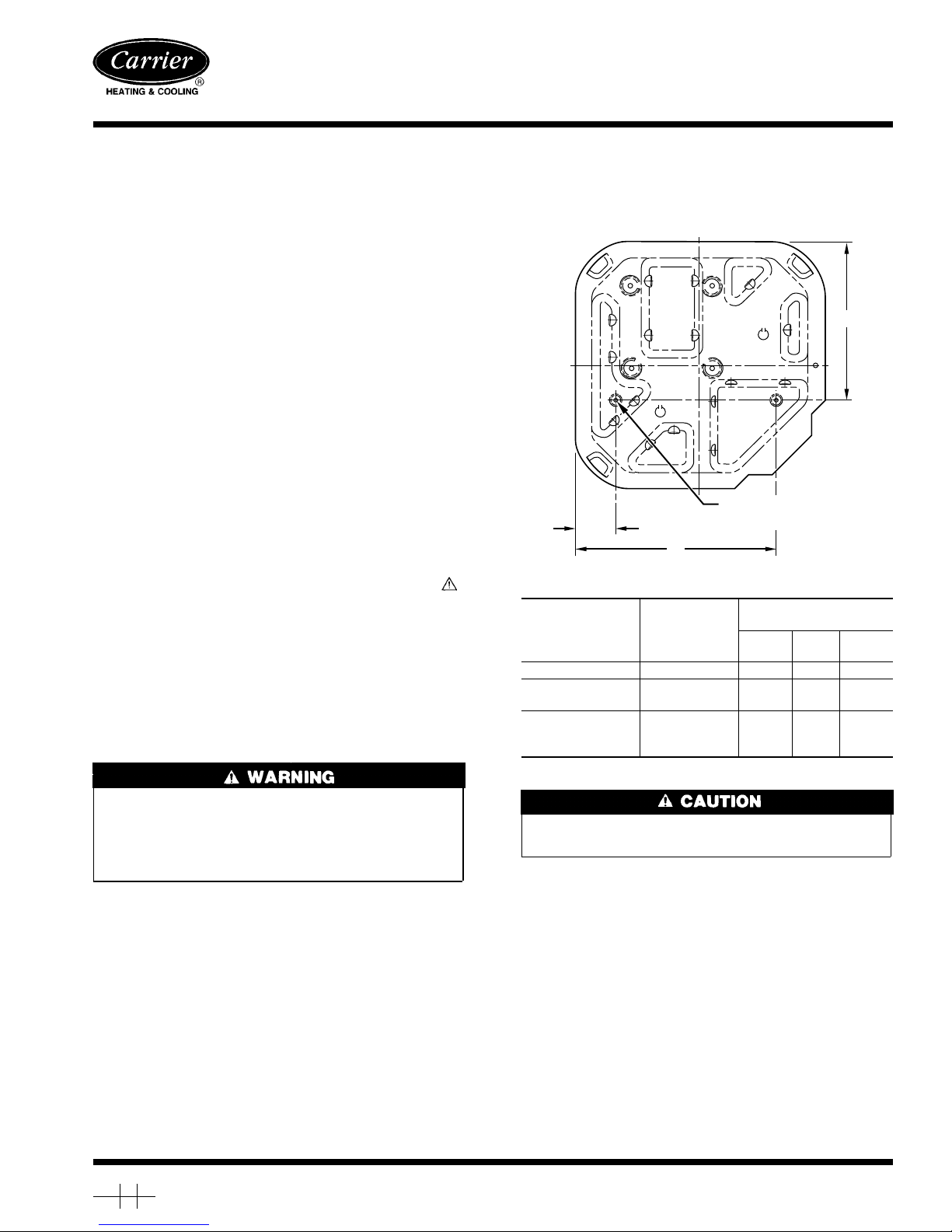
⁄8″D. (9.53) TIEDOWN
A
B
.
UNIT SIZE
38CKB(N)018, 024 18 X 18 3 15 10-3/16
38CKB(N)030-042
38CMB018-030
38BRB024-060
38CKB(N)048, 060
38CMB036-060
MIN. PAD
DIM. (IN.)
22-1/2 X 22-1/2 3-11/16 18-1/8 14-3/8
30 X 30 6-1/2 23-1/2 20
KNOCKOUTS (2) PLACES
A94199
TIEDOWN KNOCKOUT
LOCATIONS
A
(In.)B(In.)C(In.)
Fig. 1—Mount Unit to Pad
Before installing, modifying, or servicing system, main electrical disconnect switch must be in the OFF position. There
may be more than 1 disconnect switch. Lock out and tag
switch with a suitable warning label. Electrical shock can
cause personal injury or death.
INSTALLATION
Step 1—Mount Unit to Pad
Refer to Fig. 1 for pad dimensions and dimensions needed to
mount unit to pad.
Step 2—Refrigerant Tubing
Refer to Fig. 2 for refrigerant tube dimensions and connections.
Step 3—Mechanical Connection (38CKN Models)
1. Cut tubing to the correct length, deburr, and size as necessary,
making sure tube ends are square.Ifa large burr is evident, the
ID and OD must be deburred to allow tube to bottom in valve.
2. Remove lock nuts and ferrules from plastic bags taped to
service panel. (See Fig. 3.)
Manufacturer reserves the right to discontinue, or change at any time, specifications or designs without notice and without incurring obligations.
Book 1 4
Tab 3a 2a
PC 101 Catalog No. 533-837 Printed in U.S.A. Form 38CKB-1SI Pg 1 2-95 Replaces: New
If undersized, damaged, or elliptically shaped tubing is used
when making connection, leaks could result.
3. Slide the lock nut and ferrule onto each tube. (See Fig. 4.)
4. Apply a few drops of refrigerant oil to the ferrule and valve
threads to reduce assembly torque and assist sealing.
5. Insert tube end into service valve until it bottoms.
6. Push the ferrule into place and hand tighten the nut until an
increase in torque is felt.
7. Mark the nut and tube and tighten 1-1/2 turns from the mark.
(See Fig. 5.) Keep the tube bottomed in the valve while
tightening nut.
NOTE: A backup wrench on the hex part of the suction valve is
required while tightening.
Page 2
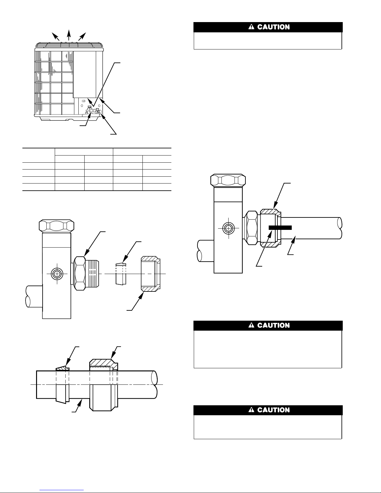
AIR DISCHARGE
The tube end must stay bottomed in the service valve during
final assembly to ensure proper seating, sealing, and rigidity.
FIELD POWER
SUPPLY CONN
7
⁄8″ DIA HOLE WITH
1
1
⁄8″ DIA KNOCKOUT
3
AND
1
⁄8″ DIA
KNOCKOUT
FIELD CONTROL
SUPPLY CONN
7
SUCTION LINE CONN
LIQUID LINE CONN
UNIT SIZE
018, 024 3/8 3/8 5/8 5/8
030, 036 3/8 3/8 3/4 3/4
042, 048 3/8 3/8 7/8 7/8
060 3/8 3/8 7/8 1-1/8
Tube diameters are for lengths up to 50 ft. For tubing lengths greater than 50
ft, consult your local distributor.
LIQUID TUBE VAPOR TUBE
Conn Dia Tube Dia Conn Dia Tube Dia
⁄8″ DIA HOLE
A93578
Fig. 2—Refrigerant Tube Dimensions/Connections
VALVE FITTING
FERRULE
MECHANICAL FITTING REPAIR
To replace damaged ferrule or tubing proceed as follows.
1. Attach gages to service valves.
2. Close liquid service valve and operate unit to pump refrigerant
charge into condenser coil.
3. When suction pressure reaches 5 psig, shut unit off. Do not
operate unit in a vacuum.
4. Close suction service valve and recover refrigerant in tubing.
5. Back-off locknut and ferrule onto tube.
6. Remove damaged part of tubing using tubing cutter. Repeat
installation procedure previously outlined using new ferrule.
7. Evacuate tubing set and indoor coil. Check for leaks.
8. Open service valves or recharge unit. Check refrigerant
charge.
LOCK NUT
LOCK NUT
A92120
Fig. 3—Mechanical Fitting Assembly (38CKN)
FERRULE LOCK NUT
TUBING
A92121
Fig. 4—Lock Nut/Ferrule Positioning (38CKN)
TUBING
MARK ON LOCK NUT
AND TUBE
A92122
Fig. 5—Proper Marking of Valve Assembly (38CKN)
Step 4—Install Solenoid Valve In Liquid Tube (If Required)
Not all applications require use of a liquid tube solenoid
valve. If your unit has been shipped with a liquid tube
solenoid valve in the unit, it must be installed for performance
enhancement. The liquid tube solenoid valve must be energized during evacuation for complete removal of refrigerant.
Before making liquid tube connections, install factory-supplied
solenoid valve on indoor liquid fitting. (See Fig. 6.) Be sure to use
flare adapter supplied with the indoor coil when making connections.
Wiring must comply with local codes and NEC requirements,
if a field-supplied control power source is needed when
adding solenoid.
1. Remove coil liquid connection cap and discard.
2. Mount solenoid valve on liquid tube, making sure valve flow
arrow points toward indoor coil. Mount valve in any position
except valve body at top and electric coil at bottom. (See Fig.
2
Page 3
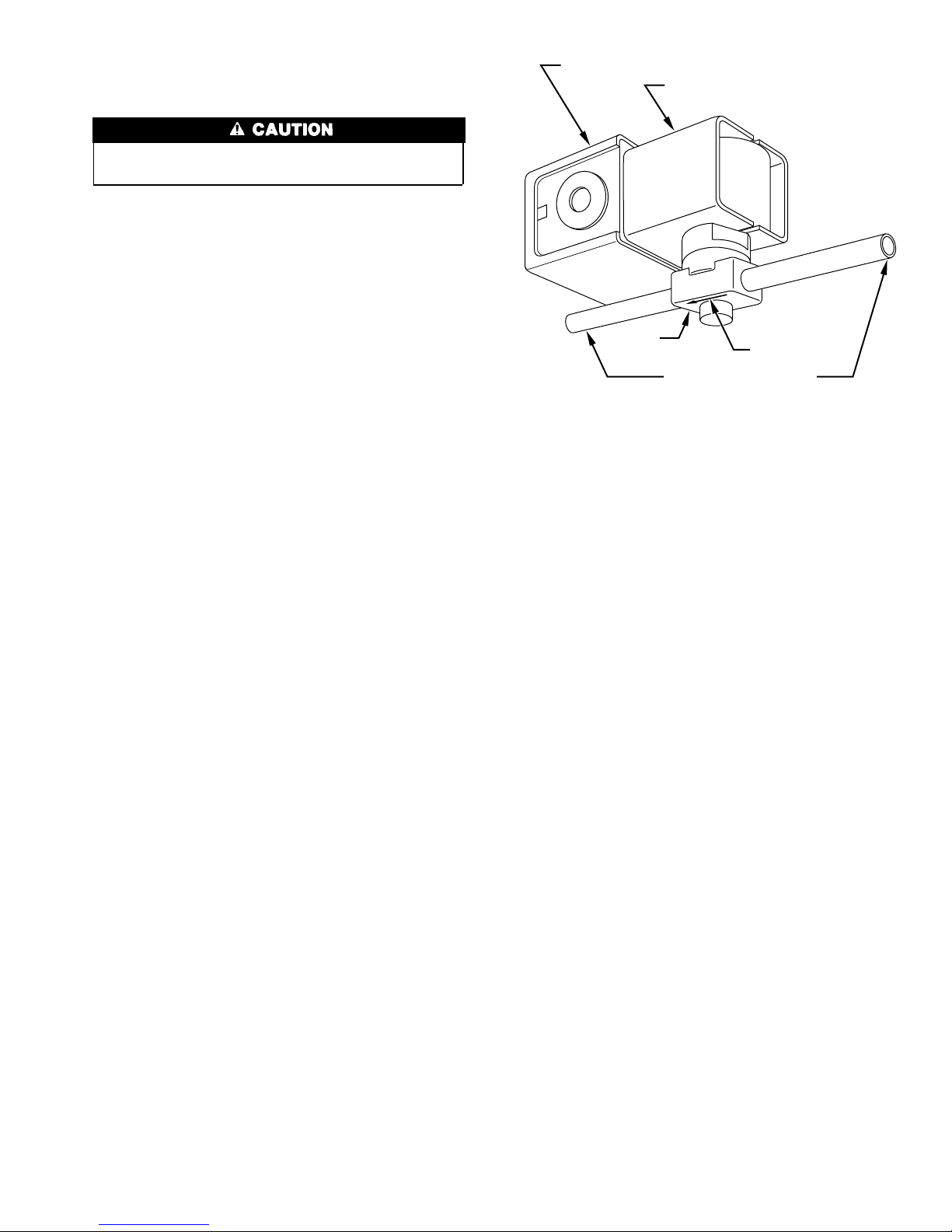
6.) The solenoid valve is to be installed a maximum of 2 ft
from indoor coil.
Avoid valve damage while brazing by wrapping valve with a
heat-sinking material such as a wet cloth.
3. Braze valve onto end of liquid tube using silver bearing or
non-silver bearing brazing material. Consult local code requirements.
4. Braze flare adapter onto outlet end of solenoid valve.
5. Wire solenoid coil into system control circuit.
ELECTRICAL JUNCTION
ELECTRICAL COIL
VALVE
FLOW ARROW
STRAIGHT 3/8 IN. STUD
NOTE:System flow direction
must match arrow on
bottom of body.
Fig. 6—Solenoid Valve Installation
A87044
3
Page 4

SERVICE TRAINING
Packaged Service Training programs are an excellent way to increase your
knowledge of the equipment discussed in this manual, including:
• Unit Familiarization • Maintenance
• Installation Overview • Operating Sequence
A large selection of product, theory, and skills programs is available, using popular
video-based formats and materials. All include video and/or slides, plus companion
book.
Classroom Service Training plus "hands-on" the products in our labs can mean
increased confidence that really pays dividends in faster troubleshooting, fewer
callbacks. Course descriptions and schedules are in our catalog.
CALL FOR FREE CATALOG 1-800-962-9212
[ ] Packaged Service Training [ ] Classroom Service Training
A94328
Copyright 1995 CARRIER Corp. • 7310 W. Morris St. • Indianapolis, IN 46231 38ckb1si
Manufacturer reserves the right to discontinue, or change at any time, specifications or designs without notice and without incurring obligations.
Book 1 4
Tab 3a 2a
PC 101 Catalog No. 533-837 Printed in U.S.A. Form 38CKB-1SI Pg 4 2-95 Replaces: New
 Loading...