

Carrier 40QNB018, 40QNE018, 40QNB024, 53QNB018, 53QNB024 Installation, Start-up And Service Instructions Manual
...Page 1
Installation, Start-Up
and Service Instructions
CONTENTS
Page
SAFETY CONSIDERATIONS ....................1
GENERAL . . . . . . . . . . . . . . . . . . . . . . . . . . . . . . . . . . . 1,2
INSTALLATION . . . . . . . . . . . . . . . . . . . . . . . . . . . . . . 2-9
Step 1 − Complete Pre-Installation Checks ....2
• UNPACK UNIT
• INSPECT SHIPMENT
Step 2 − Select Location .....................2
Step 3 − Mount Mounting Bracket on Wall ....4
Step 4 − Connect Refrigerant Piping .........5
Step 5 − Connect Condensate Drain Line .....7
Step 6 − Make Electrical Connections ........7
Step 7 − Make Connections to Outdoor Unit ..9
• COOLING-ONLY SYSTEMS
• HEAT PUMP SYSTEMS
Step 8 − Install Fan Coil Unit Onto Mounting
Bracket .....................................9
START-UP .................................9-12
40QN Control System . . . . . . . . . . . . . . . . . . . . . . . 10
After Extended Shutdowns . . . . . . . . . . . . . . . . . . 10
Seasonal Changeovers . . . . . . . . . . . . . . . . . . . . . . 10
To Turn The Unit On and Off . . . . . . . . . . . . . . . . . 10
Adjusting Airflow . . . . . . . . . . . . . . . . . . . . . . . . . . . 10
Operating Mode Memory . . . . . . . . . . . . . . . . . . . . 10
Automatic Operation (Auto) Mode ............11
Operating Fault Diagnosis ...................11
Microprocessor Control Operation ...........11
CLEANING AND MAINTENANCE ............12-14
Lubrication . . . . . . . . . . . . . . . . . . . . . . . . . . . . . . . . . 12
To Install or Replace Remote Controller
Batteries . . . . . . . . . . . . . . . . . . . . . . . . . . . . . . . . . 12
To Set the Current Time . . . . . . . . . . . . . . . . . . . . . 13
To Remove and Clean or Replace Air Filters . . 13
• TO REMOVE AIR FILTERS
• TO CLEAN OR REPLACE FILTERS
To Clean Indoor Unit Front Panel . . . . . . . . . . . . 13
To Clean Indoor Coil . . . . . . . . . . . . . . . . . . . . . . . . 13
To Clean Outdoor Coil (Outdoor Unit) . . . . . . . . 14
To Clean Condensate Drains . . . . . . . . . . . . . . . . . 14
SERVICE ..................................14,15
Diagnostic Codes . . . . . . . . . . . . . . . . . . . . . . . . . . . 14
System Tests . . . . . . . . . . . . . . . . . . . . . . . . . . . . . . . 14
• THERMISTOR TESTS
• COMPRESSOR FAILURE
• REVERSING VALVE FAILURE (38BK Only)
System Safeties and Interlocks . . . . . . . . . . . . . . 15
• INDOOR FAN FAILURE
• COMPRESSOR SHORT-CYCLING PROTECTION
• INDOOR COIL FREEZE PROTECTION (Cooling or
Dehumidification Mode Only)
• INDOOR COIL HIGH-TEMPERATURE
PROTECTION (Heat Pump Systems Only)
TROUBLESHOOTING ......................15-18
START-UP CHECKLIST ....................CL-1
SAFETY CONSIDERATIONS
Installing and servicing air-conditioning equipment can be
hazardous due to system pressure and electrical components. Only trained and qualified service personnel should
install or service air-conditioning equipment.
Untrained personnel can perform basic maintenance, such
as cleaning and replacing filters. All other operations should
be performed by trained service personnel. When working
on air conditioning equipment, observe precautions in literature and on tags and labels attached to unit.
Follow all safety codes. Wear safety glasses and work gloves.
Use quenching cloth for brazing operations. Have fire extinguisher available. Read these instructions thoroughly. Con-
sult local building codes and National Electrical Code (NEC)
for special installation requirements.
Before installing or servicing system, always turn off
main power to system. There may be more than one disconnect switch. Turn off indoor fan coil power if applicable. Electrical shock can cause personal injury.
GENERAL
The new Carrier 40QNE heat pump high wall fan coil units
(Fig. 1) DO NOT have electric heaters. These new heat pump
fan coil units have been specifically designed to improve system efficiency in both heating and cooling modes when matched
with a 38BK outdoor heat pump unit. If your application
requires heating, heat pump units must be used, both outdoors and indoors. See Table 1 for recommended system
combinations.
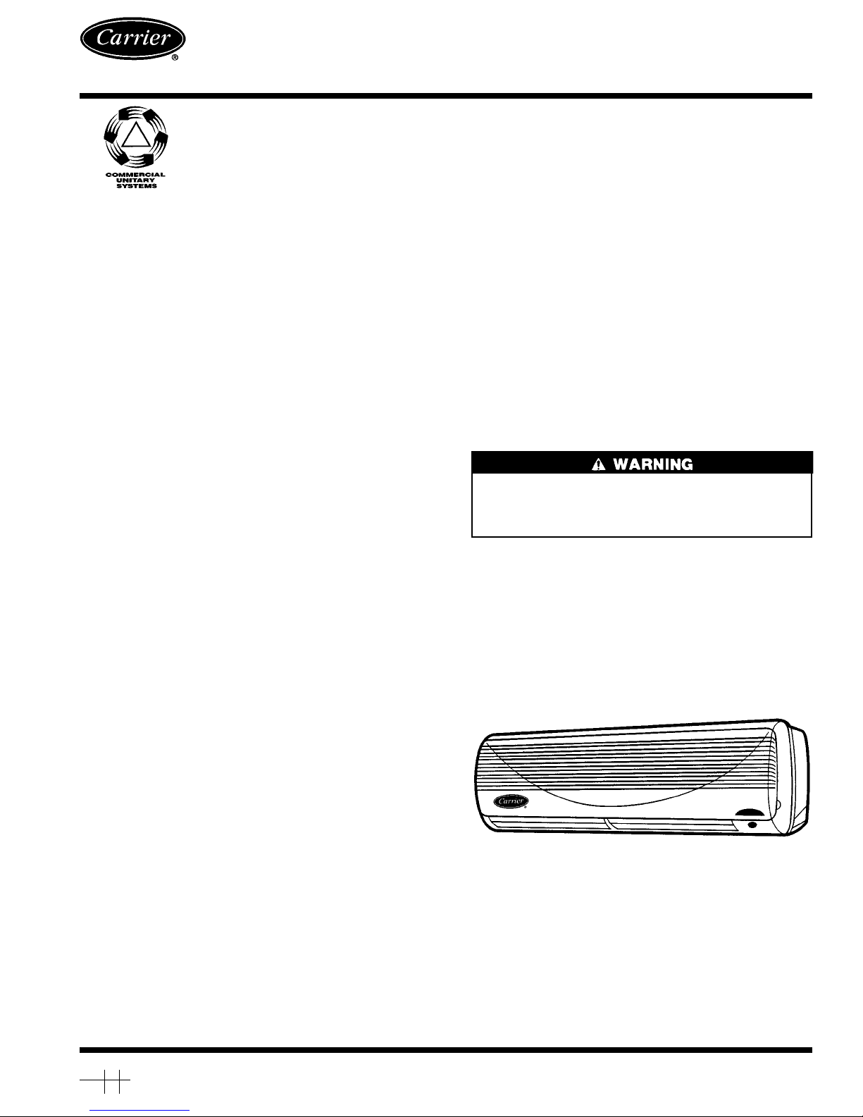
Fig. 1 — 40QN High Wall Fan Coil Unit
40QNB/QNE
018,024
High Wall Fan Coil Units
Manufacturer reserves the right to discontinue, or change at any time, specifications or designs without notice and without incurring obligations.
Book 1 4
Tab 3e 2f
PC 111 Catalog No. 534-078 Printed in U.S.A. Form 40QN-1SI Pg 1 4-96 Replaces: New
Page 2
Table 1 — System Combinations for Indoor
and Outdoor Units
SYSTEM INDOOR UNIT OUTDOOR UNIT
High Wall Cooling Only Systems
53QNB018 40QNB018 38HDC018
53QNB024 40QNB024 38HDC024
— (2) 40QNB018 38HDS024*
— (4) 40QNB018 38HDS048*
— 40QNB024, (2) 40QNB018 38HDS048*
— (2) 40QNB024 38HDS048*
High Wall Heat Pump Systems
53QNE018 40QNE018 38BK018
53QNE024 40QNE024 38BK024
*Multi-split systems can accommodate up to 4 fan coil units of vari-
ous types with one condensing unit. The combinations listed in
this table are those which use only high-wall units (not in combination with any other type of fan coil unit). Refer to system presale
literature or Price Pages for more details.
NOTE: Numbers in ( ) indicate quantities of more than 1. See Fig. 1
for 40QN high wall fan coil unit.
INSTALLATION
The 40QNB high wall fan coil unit is installed with either
the 38HDC condensing or 38HDS multi-split condensing outdoor unit, and the 40QNE unit is installed with the 38BK
heat pump outdoor unit. Refer to Table 1 to make sure the
correct indoor unit(s) is installed with the correct outdoor
unit.
Installation instructions for the 40QN fan coil units are
contained in this manual. Refer to this manual for proper
installation of the complete system. Note that the 38HDC,
HDS, and BK outdoor units are shipped with installation and
service instructions for basic installation of the outdoor section. Be sure to make the modifications in Make Connections to Outdoor Unit section on page 9 of this literature, so
that the outdoor unit will operate properly with the 40QN
control system. Be sure the unit will be operated within the
application guidelines shown in Table 2. When installing the
38HDC, HDS, or BK unit, note that for cooling operation
below 55 F (38HDC, QK) or 0°F (38HDS), it is necessary
to equip the outdoor unit with the head pressure control accessory.
To install this system, you will need:
• 40QNB or QNE fan coil unit(s)* with standard wireless
remote controller
• 38HDC, HDS, or BK outdoor unit
• low-ambient (HDC, BK) or winter start (HDS) kit (if
required for your application)
* More than one fan coil unit may be used with the 38HDS
multi-split units. Refer to 38HDS system Price Pages for
full details.
NOTE: Refrigerant pipe, drain pipe, wire, etc., are also re-
quired to install unit and are field supplied.
Be sure you have the required parts before beginning installation. The 40QN unit utilizes a microprocessor control
system to deliver optimum levels of comfort and efficiency.
Be sure to follow these instructions carefully to obtain proper
functioning of the unit.
Step 1 — Complete Pre-Installation Checks
UNPACK UNIT — Store unit in the original packaging
until it is moved to the final site for installation. When removing unit from carton, lift by its 4 corners. Also, note that
there is a plastic bag containing mounting screws taped to
the mounting bracket.
INSPECT SHIPMENT — Upon receipt of shipment check
unit (Fig. 1) for damage. Forward claim papers directly to
the transportation company. Manufacturer is not responsible
for damage incurred in transit.
Table 2 — Application Ranges
COOLING MODE
Maximum Minimum
Indoor
Unit
Outdoor
Unit
Indoor
Unit
Outdoor
Unit
95 F DB
115 F DB
67 F DB 55 F DB*
71 F WB 57 F WB 0° F DB†
HEATING MODE (38BK Systems Only)
Maximum Minimum
Indoor
Unit
Outdoor
Unit
Indoor
Unit
Outdoor
Unit
80 F DB 75 F DB
55 F DB 0° F DB
71 F WB 65 F WB
DB — Dry Bulb
WB — Wet Bulb
*38HDC and BK systems only.
†38HDS systems only.
NOTE: Unit may be equipped with a low-ambient control (HDC, BK)
or winter start kit (HDS) that will allow operation down to −20 F.
Check all items. If any item is missing notify your Carrier
distributor. To prevent loss or damage, leave all parts in original packages until installation.
Step 2 — Select Location — Consult local building
codes and NEC for special installation requirements.
There are several ways the unit may be installed to different types of wall construction. These instructions do not
cover all installation methods. As a typical installation, these
instructions focus primarily on mounting the unit to wall studs
in new construction. See Fig. 2 for unit dimensions and
Fig. 3 for required clearances. Plan your installation carefully before you begin. Listed below are some guidelines that
should be followed when determining location for the unit.
1. Center unit (horizontally) on the wall selected.
2. Place the unit so it faces normal location of room
occupants.
3. Allow sufficient space for airflow clearance, wiring, re-
frigerant piping, and servicing unit. See Fig. 2 and 3.
4. Select walls that are:
a. Strong enough to support weight of the unit.
b. Accessible to convenient condensate drainage.
c. Free of obstacles that may block air circulation to the
fan coils.
d. Outside walls (if possible) to make piping easier.
5. Place top of fan coil unit as high on the wall as possible
making sure the unit is at least 10 in. down from ceiling
to permit proper air intake. Also, make sure that the unit
is not placed directly over anything to prevent filter removal or block airflow.
6. Make sure units are easily accessible to electrical power.
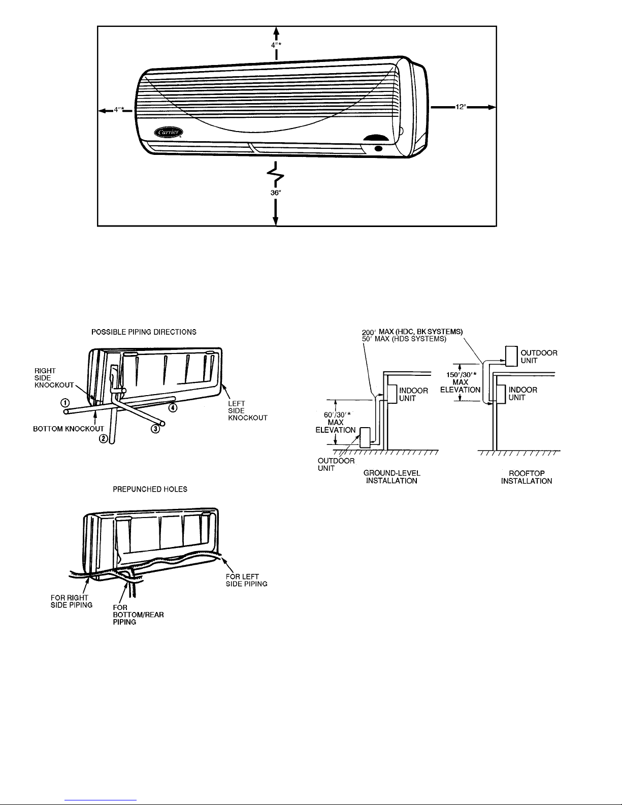
7. Refrigerant piping can enter the unit through the prepunched
holes. Refrigerant piping can run up or down along the
wall, to the right or left along the wall, straight through
the wall, or into the wall (Fig. 4). Once the piping is through
the wall, it can run inside walls, in ceilings, between floors,
or straight to the outside. See Fig. 5 for maximum line
lengths.
NOTE: Run refrigerant piping as directly as possible, and
avoid any unnecessary turns or bends.
8. Condensate piping can be directed through the inside wall
to an approved drain, or directed straight outside.
NOTE: The piping hole for condensate line must be made
at a downward slope to ensure proper drainage. See Mount
Mounting Bracket on Wall Section on page 4 for details.
2
Page 3
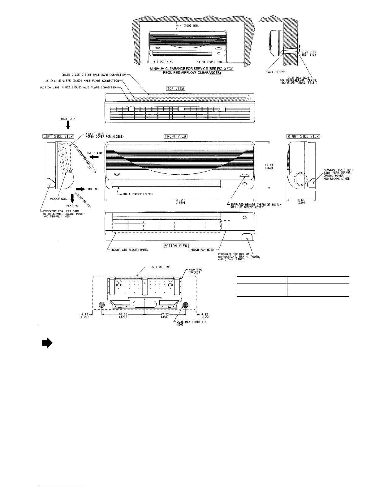
1. Dimensions in ( ) are in millimeters.
2. Direction of airflow.
3. Refrigerant, drain, and power connections may be made in unit rear, bottom, left side, or right side.
4. Refrigerant is metered by AccuRater™ device in the fan coil unit on 38HDC
and BK applications. A thermostatic expansion valve is used in the outdoor
unit on 38HDS applications. Insulate both refrigerant lines on 38HDS and
BK applications.
5. The 49 top and left side clearances are absolute minimums. Clearances of
109 are recommended.
Fig. 2 — 40QN Dimensional Drawing
UNIT WEIGHT
40QN018 39 Lb (17.5 Kg)
40QN024 43 Lb (19.5 Kg)
3
Page 4
Step 3 − Mount Mounting Bracket on Wall
1. Decide how refrigerant will be piped. If necessary, knock
out the appropriate pre-punched holes (Fig. 4) on unit for
piping and electrical connections.
2. Remove bracket from fan coil unit by pulling it down
from fan coil unit bottom as shown in Fig. 6.
3. Using a carpenter’s level, fasten mounting brackets into
the studs in the wall at least 10 in. away from the ceiling
with the 8 screws provided. Always be sure to insert screws
into the top 2 holes indicated in Fig. 6. Make sure the
attached bracket will support a 200 lb vertical load. For
amasonrywall,anchorshieldscanbeusedtoattachbracket
to the wall.
4. Temporarily hang unit on bracket to check location and
level.
*A clearance of 49 is the absolute minimum. A clearance of 109 is
recommended.
NOTE: Remove unit front cover for control box access.
Fig. 3 — Minimum Required Clearances
Fig. 4 — Refrigerant Piping
*38HDC, 38BK/38HDS systems.
Fig. 5 — Maximum Line Lengths
4
Page 5
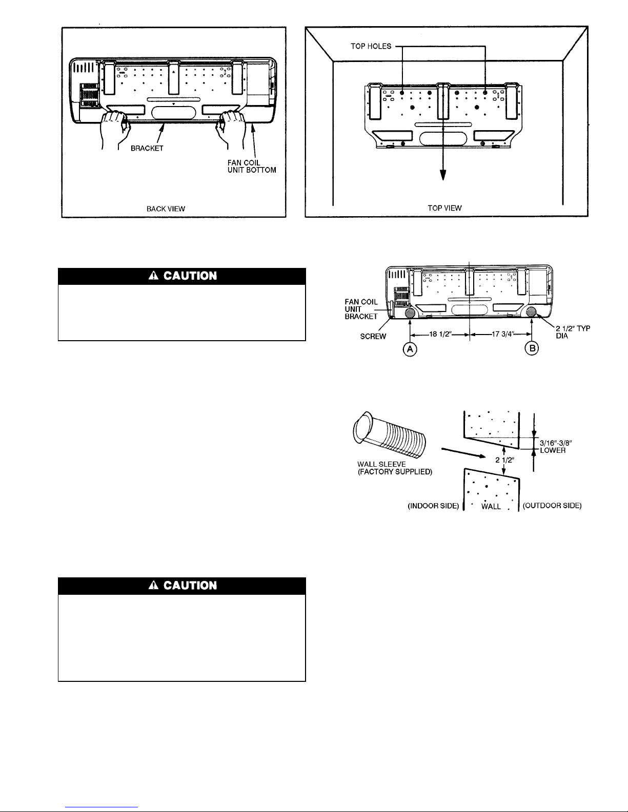
If mounting bracket is not mounted level, the indoor section will be mounted unevenly, and condensate drainage water may drip onto the floor. Also, a gap between
the bracket and the wall may result in vibration and noise
from the indoor section.
5. Mark and cut condensate and piping holes.
a. For piping through the wall, mark the wall below the
condensate connection and cut a 2
1
⁄2-in. hole into the
wall at either point ‘‘A’’ or point ‘‘B’’ in Fig. 7.
NOTE: The 2
1
⁄2-in hole must be made at a downward slope
to ensure proper condensate drainage. See Fig. 8. Slope
condensate line at a minimum pitch of1⁄4in. per foot of
line. The condensate line cannot be run up for upper piping connections − only refrigerant lines may be run up.
b. Push the wall sleeve (factory supplied with the unit)
through the 2
1
⁄2-in. wall opening.
Step 4 — Connect Refrigerant Piping — Fan coil
units may be connected to the outdoor units using fieldsupplied refrigerant grade piping. Refer to Table 3 for the
correct size piping. The length of refrigerant pipe depends
on the unit placement and building structure; run pipes as
directly as possible. For piping requirements over 50 ft of
total run, or more than 25 ft of lift, consult the long line
application guidelines available in the product presale literature, or contact your local representative.
DO NOT BURY MORE THAN 36 IN. OF REFRIGERANT PIPE IN THE GROUND. If any section of pipe
is buried, there must be a 6-in. vertical rise to the valve
connections on the outdoor unit. If more than the recommended length is buried, refrigerant may migrate to
the cooler, buried section during extended periods of unit
shutdown, causing refrigerant slugging and possible compressor damage at start-up.
Use the following instructions to connect piping.
1. Install insulation. Insulate all refrigerant lines on heat pumps
and 38HDS systems to prevent condensation. It is extremely important that all refrigerant lines and the
AccuRatert metering device be insulated on heat pumps.
On 38HDC cooling only units, the liquid line may be left
uninsulated. Use any acceptable heat resistant closed-cell
foam insulation (minimum
3
⁄8-in. wall thickness). When
insulating piping, cap ends and slide insulation over the
piping. Insulation can also be cut and placed over piping.
2. Run liquid and gas refrigerant piping.
a. Run pipes as directly as possible, and avoid any un-
necessary turns and bends.
b. Suspend refrigerant pipes so that the insulation is not
damaged and vibrations are not transmitted to the
structure.
c. Leave slack in the refrigerant pipe between the struc-
ture and the unit to absorb vibrations.
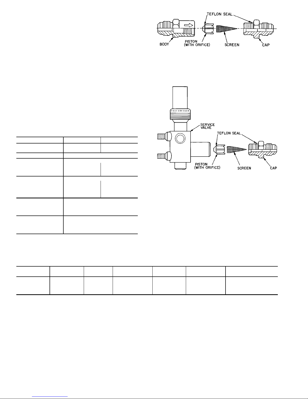
d. Install factory-supplied flare connection and Accu-
Rater metering device in liquid line at the fan coil unit
on 38HDC and 38BK systems (Fig. 9). Make sure the
arrow on the metering device body points AWAY F R OM
the fan coil unit. Use Table 4 to verify that the correct
piston for your system has been shipped with the unit.
Fig. 6 — Bracket Mounting
NOTE: Use either point ‘‘A’’ or point ‘‘B.’’
Fig. 7 — Wall Hole Location for Rear Piping
Fig. 8 — Piping Hole
5
Page 6
NOTE: No AccuRatert is required on 38HDS systems. The 38HDS systems have a TXV (thermostatic
expansion valve) in the condensing unit for refrigerant metering and control.
e. On heat pump installations, install factory-supplied pis-
ton in the AccuRater metering device located in the
service valve on the outdoor unit (Fig. 10). Make sure
Teflon seal on the piston faces toward the outdoor unit.
Use Table 4 to verify the correct piston for your system has been shipped with the unit. Refer to 38BK
installation instructions for more details.
f. Install a liquid line filter drier near the outdoor unit
(38HDC and 38BK). On heat pump systems, a bi-flow
filter drier must be used. DO NOT install a filter drier
in 38HDS systems.
3. Insulate and caulk wall openings to reduce air infiltration
and refrigerant pipe vibrations on structure.
4. Evacuate piping, if necessary. If either refrigerant piping
or the indoor coil is exposed to atmospheric conditions,
it must be evacuated to 1000 microns to eliminate contamination and moisture in the system.
Table 3 — Physical Data
UNIT 40QN 018 024
OPERATING WEIGHT
(lb)
39 43
REFRIGERANT R-22 with AccuRaterT Control or TXV
FAN
Rpm 1120 1470
Nominal Cfm
(High Speed)
540 550
COIL
Rows 23
Face Area (sq ft) 2.56 2.56
Fins/in. 15.9 18.1
Number of Circuits 23
CONNECTIONS (MPT)
Suction (in.) Flare
5
⁄
8
Liquid (in.) Flare
3
⁄
8
Condensate Drain
5
⁄
8
LINE SIZES
Suction (in.)
5
⁄
8
Liquid (in.)
3
⁄
8
Condensate Drain
5
⁄
8
TXV — Thermostatic Expansion Valve
(38HDS only)
Table 4 — Required Piston Sizes for AccuRater Metering Device
OUTDOOR
UNIT 38
INDOOR
UNIT 40QN
INDOOR
PISTON
INDOOR
PISTON TYPE
OUTDOOR
PISTON
OUTDOOR
PISTON TYPE
REQUIRED SYSTEM
CHARGE (lb)*
HDC018 B018 49 B N/A N/A 4.6
HDC024 B024 57 B N/A N/A 5.3
BK018 E018 51 B 47 B 5.0
BK024 E024 59 B 52 B 5.1
LEGEND
N/A — Not Applicable
TXV — Thermostatic Expansion Valve
*Charge amount determined based on 25 ft of line. Check charge for longer lines using superheat method. See 38HDC and BK installation, start-up,
and service instructions for system charging procedures.
NOTE: The 38HDS systems do not use the AccuRater device. The 38HDS systems have a TXV in the condensing unit for refrigerant metering and
control.
NOTE: Arrow on AccuRater body points in
free flow
direction away
from the coil.
Fig. 9 — AccuRater Metering Device in Liquid
Line (Bypass Type Components)
Fig. 10 — AccuRater Metering Device at Service
Valve (Bypass Type Components)
6
Page 7
Step 5 — Connect Condensate Drain Line —
Observe all local sanitary codes when installing condensate
drains.
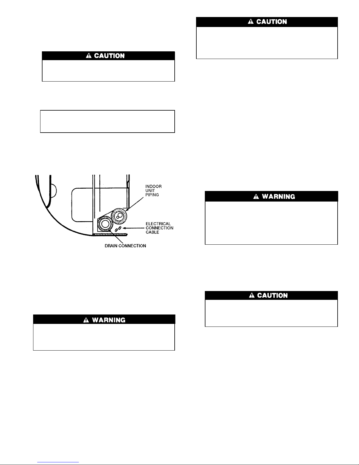
1. Connect drain line by inserting a
5
⁄8-in. rigid PVC pipe
over the drain connection. Refer to Fig. 11.
The drain tube extension must be securely fastened
to the condensate drain. Failure to do so can result
in condensate water dripping onto the floor.
2. To ensure regular flow of condensate water, the drain pipe
should be pitched toward an open drain or sump at a downward slope of at least1⁄4-in. per foot. Refer to Fig. 12.
IMPORTANT: Be sure the drain piping has no slack
which might form a trap. Do not insert a trap in the
drain line; the drain is internally trapped.
3. Insulate condensate drain line(s). Insulate the condensate
drain lines that are located in or above an occupied area
with a condensate proof material such as polyurethane or
neoprene.
Step 6 — Make Electrical Connections — Be sure
field wiring complies with local building codes and NEC,
and unit voltage is within limits shown in Table 5.
Contact local power company for correction of improper
line voltage.
To avoid personal injury or damage to unit, do not make
electrical connections until all power sources are shut
down, locked out, and tagged off. Failure to do so could
result in personal injury or unit damage.
Operation of unit on improper line voltage constitutes
abuse and could affect warranty. Refer to Table 5 for
permissible operating limits. Do not install unit in system where voltage may fluctuate above or below permissible limits.
NOTE: Use type NM power cable only (per NEC; provided
for fan coil units only) between disconnect switch and unit.
NOTE: Install branch circuit disconnect per NEC of adequate size to handle unit starting current. Locate disconnect
within sight from and readily accessible from unit, per
Section 440-14 of NEC. Some codes allow indoor unit to
share disconnect with outdoor unit if disconnect can be locked;
check local code before installing in this manner. To make
electrical connections:
1. Remove the screws holding the front cover of the fan coil
unit, and remove front cover. Save screws and screw
covers for reinstallation.
2. Remove control box strain relief clamp (see Fig. 13).
3. Remove any factory test leads still connected to the power
terminal box. These leads (if applicable) are for factory
testing only and cannot be used for power connections.
4. Route the factory-supplied ground and power wires from
terminal block 1 (TB1) to the field-supplied disconnect
switch.
According to NEC and most local codes, the unit
must have an uninterrupted, unbroken ground to minimize personal injury if an electrical fault should occur. The ground may consist of electrical wire or
metal conduit when installed in accordance with existing electrical codes. Failure to follow this warning could result in an electric shock, fire, or death.
5. Route factory-supplied line power leads (see Fig. 14) from
field-supplied, indoor unit disconnect to the fan coil unit
TB1 (see Fig. 14 and 15). Run wire through the strain
relief on the control box (see Fig. 13). When routing wire
in the fan coil unit, keep the wire away from refrigerant
and condensate piping and any sharp edges on the unit.
Do not short circuit the 40QN transformer − it is
fused. The transformer can be short circuited by connecting the wrong wires or by touching a live wire
to the side of a grounded control box.
Fig. 11 — Drain Connection (Right Side Shown When
Facing Fan Coil Unit)
7
Page 8
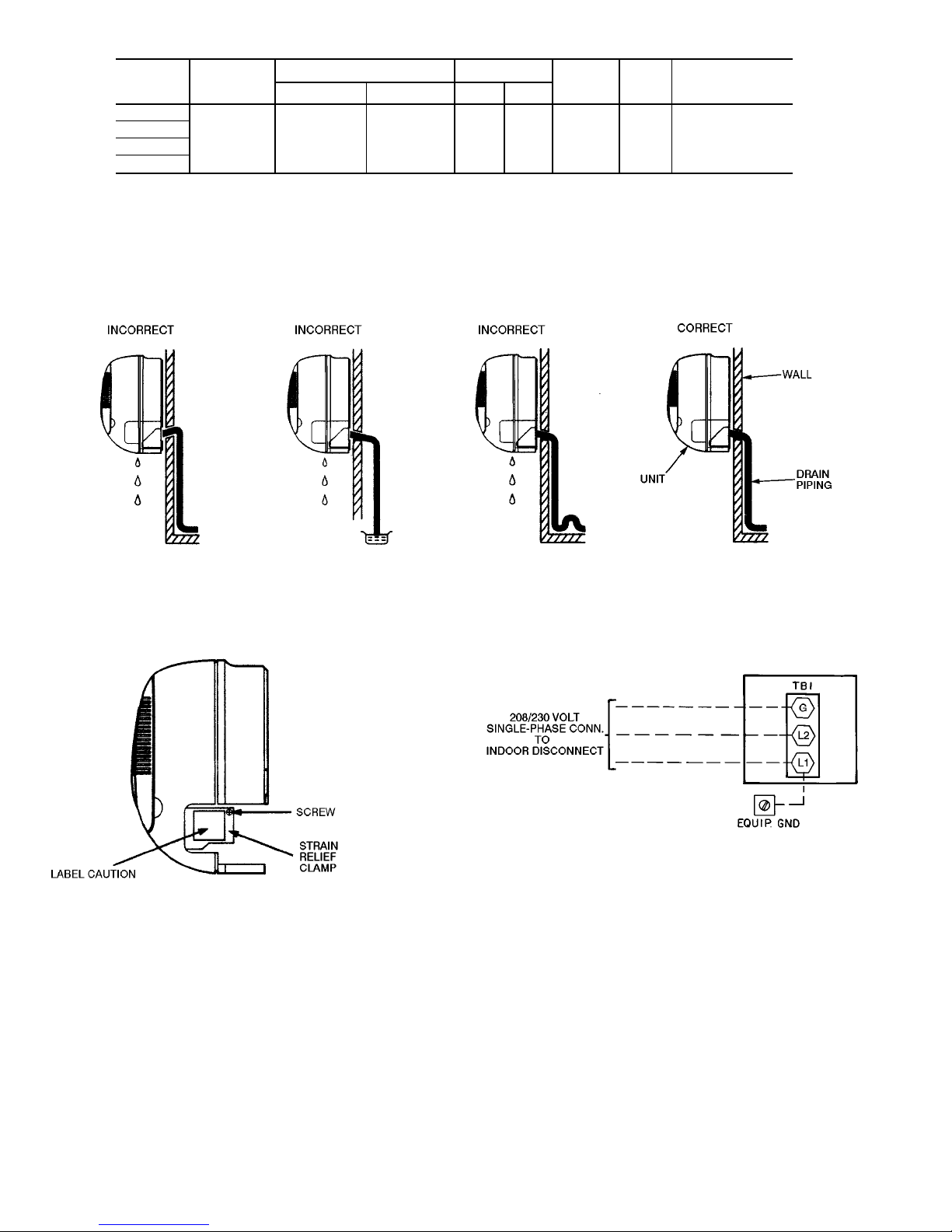
Table 5 — Electrical Data
INDOOR
UNIT
40QN
V (Single-
Ph, 60 Hz)
OPERATING VOLTAGE* FAN
WATTS MCA
MAX FUSE
OR HACR TYPE
CKT BKR AMPS
Max Min LRA FLA
B018
208/230 253 187 3.2 0.53 94 0.66 15
B024
E018
E024
LEGEND
FLA — Full Load Amps
HACR — Heating, Air Conditioning, and Refrigeration
LRA — Locked Rotor Amps
MCA — Minimum Circuit Amps per NEC Section 430-24
NEC — National Electrical Code
*Permissible limits of the voltage range at which unit will operate satisfactorily.
Fig. 12 — Drainage System (Rear Piping Shown)
NOTE: This shows item locations only. Front cover of fan coil unit
must be removed to access terminal boards.
Fig. 13 — Fan Coil Unit Wiring Preparation
FAN COIL UNITS
LEGEND
CONN — Connection
EQUIP GND — Equipment Ground
TB — Terminal Block
Fig. 14 — Line Power Connections
8
Page 9
Step 7 − Make Connections to the Outdoor Unit
COOLING-ONLY SYSTEMS − To connect the 38HDC or
HDS condensing unit to the fan coil unit(s) so that the system will operate correctly:
Route 2 field-supplied wires of 18-gage AWG (American
Wire Gage) thermostat cable between the low-voltage terminal block of the fan coil unit (TB2) and the 38HDC or
HDS unit low-voltage terminal block. Connect the wires between terminals Y and Y and between terminals C and C.
HEAT PUMP SYSTEMS − To connect the 38BK heat pump
unit to the fan coil unit so that the system will operate
correctly:
IMPORTANT: DO NOT RUN THE THERMISTOR
CABLE IN THE SAME CONDUIT AS THE POWER
WIRING.
1. One thermistor connection cord with a lead length of
24 ft is shipped with the 40QNE fan coil unit. Run the
connection cord from the low-voltage terminal board in
the control box in the fan coil unit (TB3) to the heat pump
unit. Route the wire carefully so that it will not be
damaged.
2. For cooling operation, route 2 field-supplied wires of
18-gage AWG (American Wire Gage) thermostat cable
between the low-voltage terminal block of the fan coil
unit (TB2) and the 38BK unit low-voltage terminal block.
Connect the wires between terminals Y and Y and between terminals C and C.
3. For heating operation, route 3 additional wires of
18-gage AWG thermostat cable between the low-voltage
terminal block of the fan coil unit (TB2) and the 38BK
unit low-voltage terminal block. Connect the wires between terminals R and R, O and O, and G and G.
Step 8 − Install Fan Coil Unit Onto Mounting
Bracket
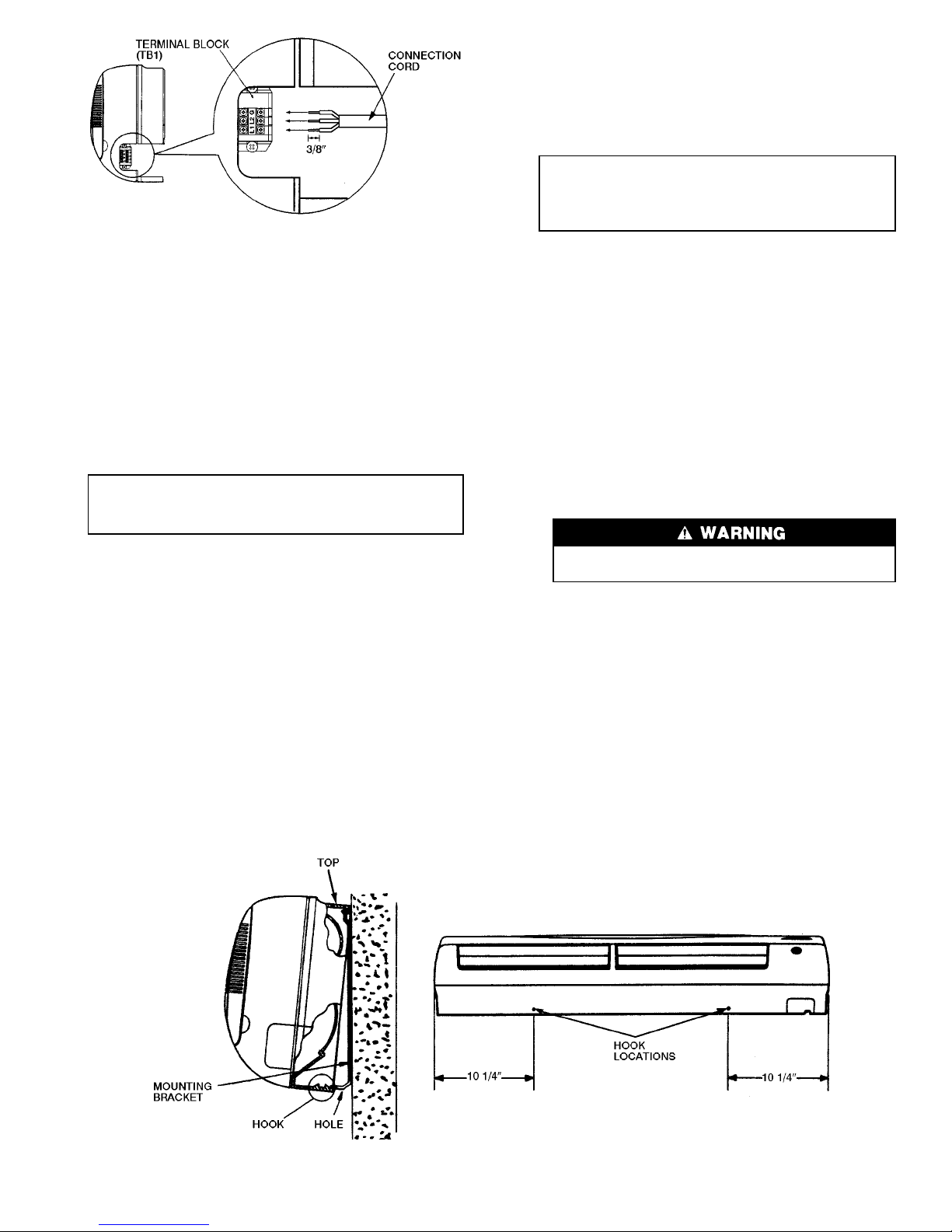
1. Hook the fan coil unit onto the top of the mounting bracket.
See Fig. 16.
2. Snap the fan coil unit onto the mounting bracket as shown
in Fig. 16.
IMPORTANT: An audible snapping sound will be
heard as the hook on the unit is secured into the
hole on the mounting bracket. Be sure unit is correctly mounted.
START-UP
Complete the following checks and the Start-Up Checklist on page CL-1 before system start-up. Refer to outdoor
unit installation, start-up and service instructions for system
start-up procedures and refrigerant charging methods.
1. Check condensate drainage system.
Add water to check the drainage flow. If water does not
flow regularly, check the pipe slope or see if there are
any pipe restrictions.
2. Make sure that all wiring connections are correct and
tight.
3. Make sure that all barriers, covers, and panels are in place.
4. Ensure that the filters have been installed and that the
discharge louvers are correctly positioned.
Never operate unit without a filter. Damage to the
unit or personal injury may result.
5. If the unit is equipped with a crankcase heater, energize
a minimum of 24 hours before starting the unit. To energize crankcase heater only, close indoor unit disconnect, then with the remote controller, set unit in off mode
and close the outdoor unit disconnect.
6. Fully backseat (open) the liquid and vapor tube service
valves.
7. Unit is shipped with valve stems frontseated and caps
factory installed. Replace stem caps after system is opened
to refrigerant flow (backseated). Replace caps finger tight.
Fig. 15 — High Voltage Connections
Fig. 16 — Mounting Unit to Bracket
9
Page 10
8. With the remote controller, turn on the unit and operate
in each mode (as applicable) for 15 minutes to test for
proper operation. Do not operate in cooling mode if outdoor temperature is below 55 F (HDC,BK) or 0° F (HDS)
unless unit is equipped with low ambient control (HDC,
BK) or winter start kit (HDS). Do not operate in heating
mode (heat pump systems only) if the outdoor temperature is above 75 F.
9. Test for proper refrigerant charge using the superheat
method (HDC,BK) or subcooling method (HDS).
10. Explain basic system operation to the owner.
40QN Control System — The 40QN unit is equipped
with a microprocessor control which operates the system.
This control is located in the control box of the fan coil unit,
with thermistors located in the fan coil inlet and on the indoor coil. The 40QNE heat pump fan coil units also have
thermistors located on the outdoor coil and in the outdoor air
inlet. These thermistors monitor system operation and control the operating mode. To change settings or modes of operation, use the factory-supplied infrared wireless remote
controller. This controller allows the fan coil unit to be operated from within the same room without any wire connections to the unit.
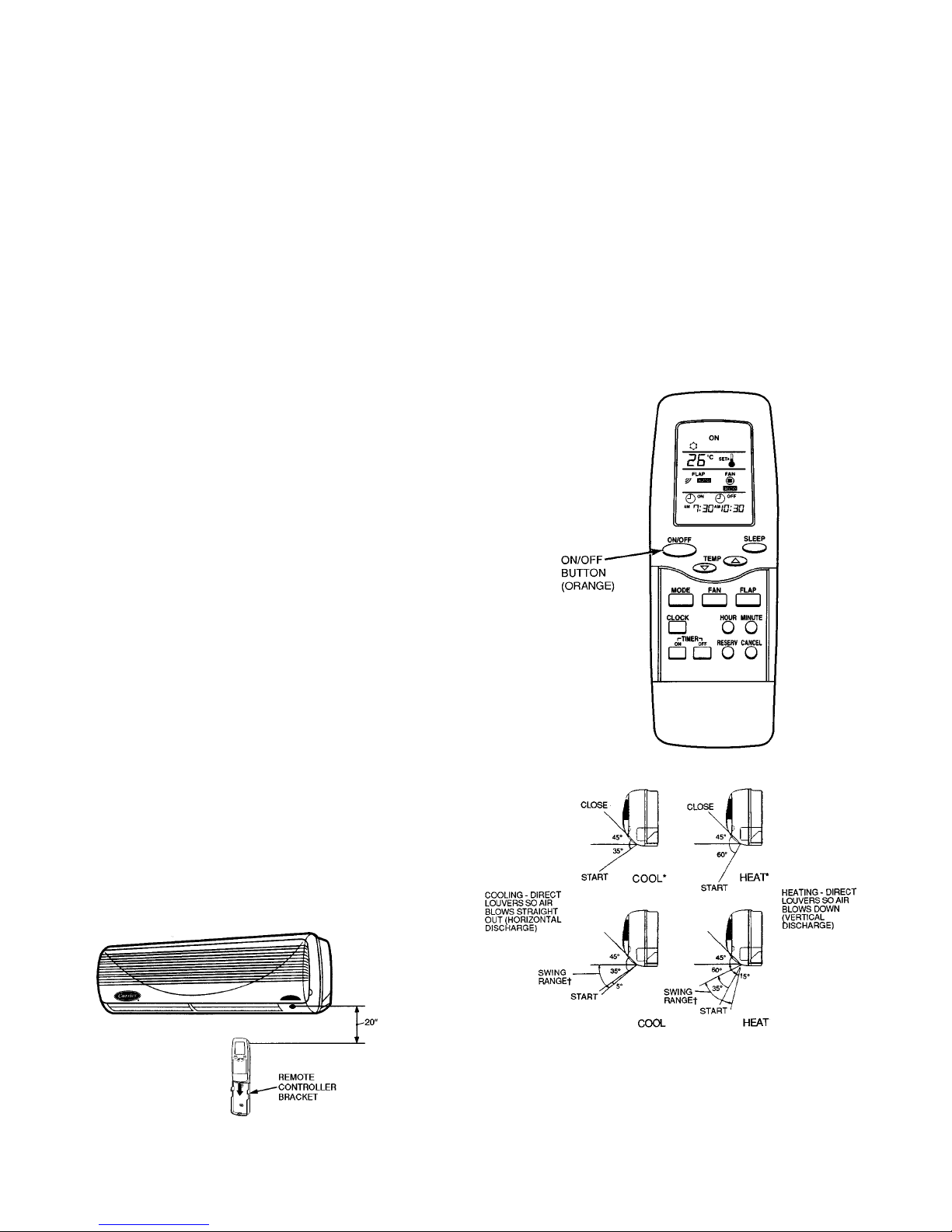
The remote controller includes a wall-mounted bracket.
To install the bracket, attach bracket to the wall as shown in
Fig. 17 using factory-supplied, double-sided tape. Install factorysupplied batteries into the remote controller per To Install or
Replace Remote Controller Batteries section on page 12, and
place the controller into the bracket so that it will be ready
for use.
After Extended Shutdowns — If the system has been
turned off for more than 12 hours, turn on the indoor and
outdoor unit disconnect switches to supply power to the system for 12 hours BEFORE starting the system.
Seasonal Changeovers — When changing heat pump
system from cooling to heating or heating to cooling, or before starting cooling only system after it has been out of use
for the winter season, perform the following steps BEFORE
starting the system:
1. Inspect and clean the outdoor unit, particularly the coil.
2. Clean or replace the air filters in the indoor unit.
3. Clean the indoor unit drain pan and drain pipe, and re-
move any obstructions.
4. Turn on indoor and outdoor unit disconnect switches to
supply power to the system 12 hours before starting the
system.
To Turn the Unit On and Off — To turn the unit on,
press the orange ON/OFF button (See Fig. 18). Unit will start.
To stop unit operation, press the ON/OFF button again. Unit
will stop. Refer to Owner’s Manual enclosed with the fan
coil unit for full remote control operating details.
Adjusting Airflow — The airflow direction may be ad-
justed up and down using the remote controller, and from
side to side by manually moving the vents. For cooling only
units and heat pump units when in the cooling mode, set the
louvers to discharge straight out (parallel to the floor) (see
Fig. 19). For the heat pump units operating in heating mode,
it is recommended that the air discharge louvers be set to
discharge vertically (see Fig. 19).
The swing range shown in Fig. 19 is the range which will
provide maximum occupant comfort in each mode. It is recommended that the louvers be positioned within this range
(using the remote controller).
NOTE: The full swing range for the mode selected will automatically be used if auto. fan mode is selected.
Operating Mode Memory — After the system is turned
off or after a power failure, the system remains in the last
operating mode selected. When the system is turned back
on, or when power is automatically restored, operation continues in the same operating mode as when power shut down.
Fig. 17 — Mounting Remote Controller Bracket
Fig. 18 — Remote Controller
*Potential range.
†Desirable range.
NOTE: Unit is equipped with manual air vents which direct the air
from side to side. Up and down louver motion can be selected using
the remote controller. For maximum comfort, set louvers within the
swing range. See Adjusting Airflow section on this page for more
information.
Fig. 19 — Louver Adjustments
10
Page 11

Automatic Operation (Auto) Mode — If auto mode
is selected, the system automatically switches the operating
mode from heating (heat pump system only) to cooling, or
from cooling to heating (heat pump system only) depending
on the selected temperature.
NOTE: Between the cooling cycle and the heating cycle there
is a neutral zone of approximately 2° F above and 2° F below the selected temperature when only the fan is operating.
Operating Fault Diagnosis — The system includes
an automatic diagnosis feature which is activated under
difficult or unacceptable operating conditions. If such conditions occur, the system stops automatically, the operating
fault signal appears (green ‘‘UNIT ON’’ light on the front of
the fan coil unit flashes), and an analysis of the system operating conditions is initiated. The system will then be restarted automatically, as soon as normal conditions have been
restored, or it will remain off. If the system does not start
again, the green ‘‘UNIT ON’’ light will flash an error code.
Microprocessor Control Operation — This sys-
tem is controlled by a microprocessor designed to give optimum levels of comfort and operating efficiency. The control is located in the 40QN unit. To operate the unit, the factorysupplied remote controller is required.
There are 9 (QNB systems) or 11 (QNE systems) operating modes (including the off mode) for the unit. Each mode
operates as follows:
• Off Mode — When the unit is in the off mode, all func-
tions (compressor, outdoor fan, indoor fan, and air sweep)
are off, except the reversing valve (QNE only), which will
stay energized if the unit was last operated in the cooling
mode.
• Air Circulation Mode (Fan Operation Only) — When air
circulation mode is selected, the indoor fan will operate
continuously in the selected speed (high, medium, low, or
auto.). If the auto. mode is selected, the indoor fan will
operate at low speed. The compressor and outdoor fan are
off. The reversing valve (QNE only) will remain in the
last operating mode.
• Cooling Mode — When the cooling mode is selected, the
indoor fan will operate continuously at the selected speed
if the speed is high, medium, or low. If the indoor fan is
in auto. mode, the fan will change operating speeds depending on the difference between the room temperature
and the set point. The reversing valve (QNE only) will be
on. The compressor cannot run for 3 minutes from the time
the system starts up or for 3 minutes from the time the
compressor last operated. When the temperature of the room
is equal to or greater than the selected temperature, the
compressor and outdoor fan will operate until the room
temperature is 2° F below the set point, and then shut off.
When the room temperature is less than the selected temperature, the compressor and outdoor fan remain off.
•MaximumDehumidificationMode—Whenthedehu-
midification mode is selected, the indoor fan will operate
continuously at the selected speed if the speed is high, medium, or low. If the indoor fan is in auto. mode, the fan
will change operating speeds depending on the room temperature. If the room temperature is below the set point,
the indoor fan will run at ultra-low speed, and the compressor could run for up to 4 minutes. (Ultra-low speed is
acontrol-drivenspeed[notuserconfigurable]usedtosample
the space when the fan would normally be off.) The reversing valve (QNE only) will be on. The compressor cannot run for 3 minutes from the time the system starts
up or for 3 minutes from the time the compressor last
operated.
Initial Operation — When the mode is first selected, one of
the following occurs:
1. If the room temperature is above or equal to the selected
temperature, the unit will operate for 16 minutes, and the
compressor and outdoor fan will operate. The indoor fan
will operate as in the cooling mode. After 16 minutes of
operation (or when the room reaches 2° F below set point),
the unit switches to normal dehumidification operation.
2. If the room temperature is below the selected temperature, the unit will operate for 8 minutes as follows: the
compressor and outdoor fan will operate for 3 minutes.
The indoor fan will operate in low speed, and 30 seconds
after the compressor stops, the indoor fan stops. The unit
remains off for 1 minute, and then the indoor fan starts in
ultra-low speed for 30 seconds. The unit then switches to
normal dehumidification operation.
Normal Operation — One of the following will take place:
1. When the temperature of the room is equal to or greater
than the selected temperature (by not more than 3° F), the
unit will operate for 8 minutes as follows: the compressor and outdoor fan will operate for 3 minutes. The indoor fan will operate in low speed, and 30 seconds after
the compressor stops, the indoor fan stops. The unit remains off for 1 minute, and then the indoor fan starts in
ultra-low speed for 30 seconds. The normal dehumidification operation is repeated for the newly sensed room
temperature.
2. If the room temperature is equal to or greater than the
selected temperature, but not by more than between 4° F
and 6° F, the compressor and outdoor fan operate for
4 minutes. The indoor fan will run at ultra-low speed and
will stop 30 seconds after the compressor stops. After
3 minutes, the indoor fan runs at ultra-low speed for
30 seconds. The normal dehumidification operation is repeated for the newly sensed room temperature.
3. When the room temperature is equal to or greater than
4° F below the selected temperature, the system operates
as follows: The compressor and outdoor fan operate for
3 minutes. The indoor fan will operate at ultra-low speed
and will stop 30 seconds after the compressor stops. After 4 or 5 minutes, the indoor fan starts in ultra-low speed
for 30 seconds. The normal dehumidification operation is
repeated for the newly sensed room temperature. If the
room temperature is still 4° F below the selected temperature, the compressor, outdoor fan, and indoor fan remain off. After 7
1
⁄2minutes, the indoor fan operates at
ultra-low speed for 30 seconds. The normal dehumidification operation is repeated for the newly sensed room
temperature.
• Heat Pump Heating Mode (Heat Pump Systems Only) —
When the heat pump mode is selected, the indoor fan will
operate at the selected speed if the speed is high, medium,
or low, unless overridden by the coil temperature (to prevent cold drafts). If the indoor fan is in auto. mode, the fan
will change operating speeds depending on the difference
between the room temperature, the set point, and the coil
temperature. The reversing valve will be off. The compressor cannot run for 3 minutes from the time the system
starts up or for 3 minutes from the time it last operated.
When the temperature of the room is 8° F below the selected temperature, the unit will operate in heat pump mode
until the temperature is 6° F above the selected temperature, or the compressor runs for 40 minutes (whichever
comes first). If the temperature of the room is less than
7° F below or equal to the selected temperature, the unit
operates in heat pump mode until the selected set point
temperature plus 2° F is reached.
•DemandDefrostMode(HeatPumpSystemsOnly)—This
unit uses a demand defrost system to remove frost from
the outdoor coil during heating operation. The indoor and
outdoor fans are shut off during defrost mode.
11
Page 12
• Sleep Mode — The sleep mode timer will turn the unit off
when the timer reaches zero minutes. During the first
11⁄2hours from the time the sleep mode timer starts, the
room temperature is set back from the selected temperature a total of 4° F in cooling and 6° F in heating
(BK only).
• Awake Mode — The awake timer will turn the unit on
when the timer reaches zero minutes. The unit will start in
the same mode and at the same selected temperature as
when the system shut off.
•AutomaticOperationModeforCoolingOnlySystems
(38HDC and HDS) — The unit samples the air in the room.
Based on the room temperature, the unit selects one of the
following modes:
1. Cooling Mode — If the room temperature is more than
82.4 F with a preset temperature of 78.8 F.
2. Dry Mode — If the room temperature is more than
75.2 F and less than 82.4 F with a preset temperature of
77 F.
3. Fan Only Mode — If the room temperature is less than
75.2 F.
The preset temperature can be changed by ±4° F using the
remote control.
•AutomaticOperationModeforHeatPumpSystems(38BK)
— The operation mode will be determined after 20 seconds of room monitoring (to determine the room temperature and the outdoor air temperature).
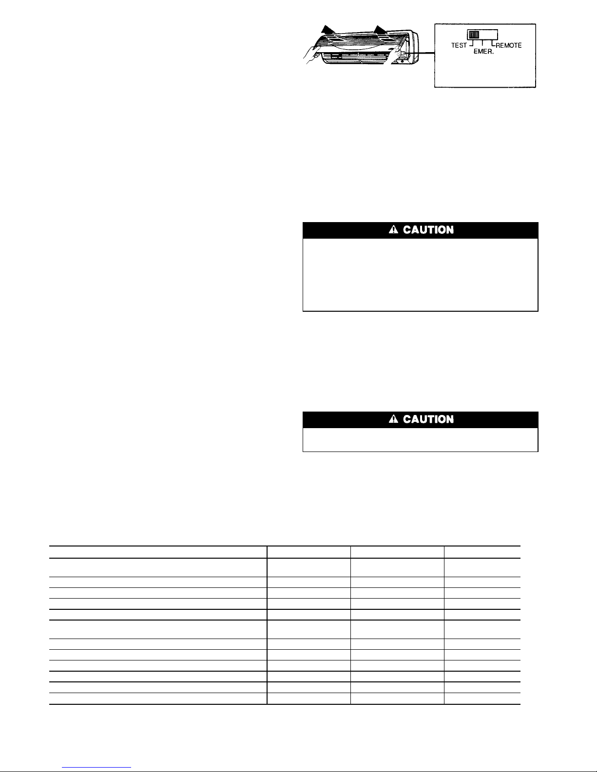
• Test Mode — The test mode can be selected by setting the
slide switch on the fan coil unit to TEST position. The
slide switch is located on the front of the unit as shown in
Fig. 20. The fan coil unit will start immediately (there is
no compressor time delay when using test mode) in cooling mode with an infinitely low set point. The indoor fan
speed will be at the high setting, and the swing louvers
will be on (moving up and down).
NOTE: The unit cannot be controlled by the remote controller until the slide switch is returned to the REMOTE
position.
• Emergency Mode — This mode is only to be used if the
remote controller is lost, damaged, or the batteries are discharged. To initiate emergency mode, manually move the
slide switch on the fan coil unit to the EMER position
(Fig. 20). The unit is automatically operated in cooling or
heating (BK units only) mode according to room temperature. Emergency operation settings are as follows:
1. Operation mode: AUTO.
2. Fan Speed: AUTO.
3. Cooling set point: 77 F
4. Timer Mode: Continuous
NOTE: The unit cannot be controlled by the remote con-
troller until the slide switch is returned to the REMOTE
position.
CLEANING AND MAINTENANCE
To avoid the possibility of electric shock, before performing any cleaning and maintenance operations, always turn off power to the system by pressing the
orange ON/OFF button on the remote controller. Turn
off the outdoor disconnect switch located near the outdoor unit. If the indoor unit is on a separate switch, be
sure it is also disconnected.
For proper system operation, perform the cleaning and main-
tenance operations in Table 6.
Lubrication — The indoor-fan automatic air sweep mo-
tor, and the outdoor fan motor are factory lubricated and require no oiling.
To Install or Replace Remote Controller
Batteries
Do not drop the remote controller — damage to the
device may result. Avoid getting the controller wet.
NOTE: Before replacing the batteries, note that the remote
controller signal can be affected if electronic fluorescent
lights are installed nearby. The batteries may not need to be
replaced. If you suspect this is the problem, consult your
Carrier distributor.
Table 6 — Cleaning and Maintenance Schedule
TASK MONTHLY QUARTERLY YEARLY
INDOOR UNIT
Clean Air Filters X
Clean Drain Pipe X
Clean Condensate Drain Pan X
Replace Batteries in the Remote Controller X
Clean Indoor Unit Front Panel X
OUTDOOR UNIT
Clean the Fins From Outside X
Open the Unit and Clean Fins Inside X
Remove Dust From Electrical Parts X
Check Electrical Connections are Tight X
Clean Outdoor Fan X
Check that Outdoor Fan Assembly is Tight X
Clean Drain Pan X
NOTE: Maintenance procedures for the outdoor unit are in the 38HDC, HDS, and BK installation instructions.
EMER — Emergency Mode
Fig. 20 — Slide Switch
12
Page 13
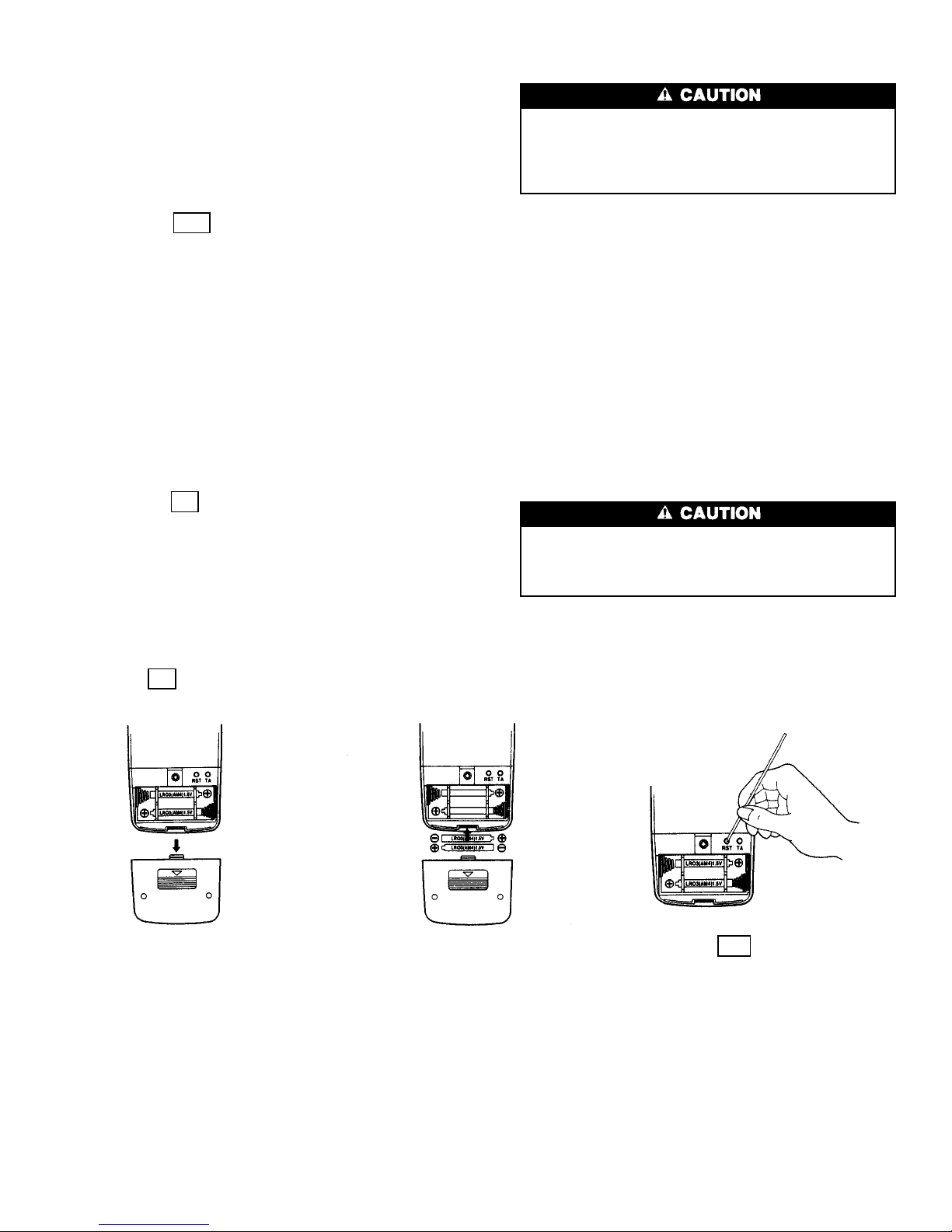
Batteries should be replaced once a year. Use 2 batteries (1.5
v, dc-t ype, AAA alkalin e batte ries ). Neve r use o ld or r echarged batteries together with new ones.
To replace batteries:
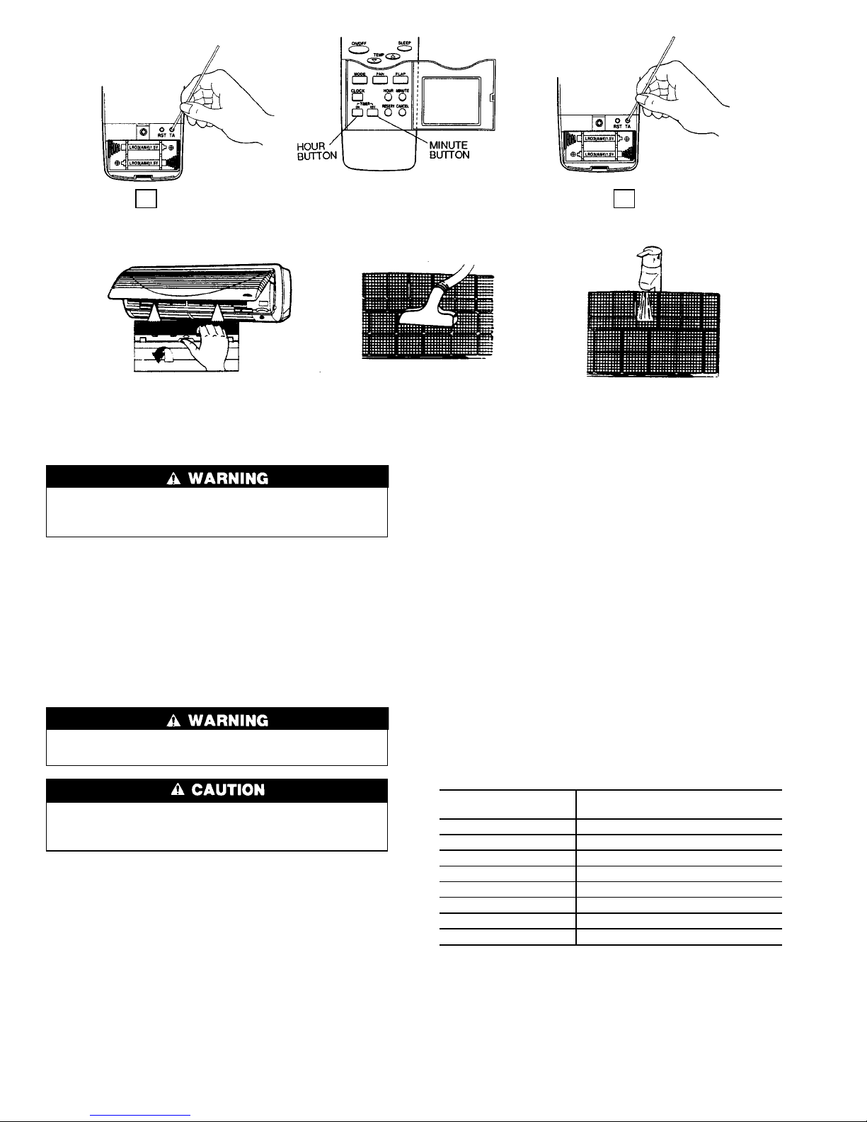
1. Slide the battery cover off from the back of the remote
controller. See Fig. 21.
2. Insert the 2 batteries in accordance with the markings
on the remote controller, so that the poles are correct
(+ and −).
RST
3. Press the button using an instrument screwdriver
or similar small, pointed tool.
4. Replace the cover securely.
It is time to replace the remote controller batteries when
the remote controller function becomes irregular, or the system no longer responds to commands given close to the unit.
When shutting down the system for an extended period of
time, it is advisable to remove the batteries.
Consult distributor if any other equipment is turned on or
shows signs of disrupted operation if you use the wireless
remote controller, or if the system is turned on or shows signs
of disrupted operation when the remote controller of any other
equipment is used.
To Set the Current Time
TA1. Press the button (located on the back of the remote
controller; see Fig. 22) with an instrument screwdriver or
similar small, pointed tool, and the current time indication symbol flashes.
Note that the controller comes preset from the factory set for
6:00 a.m.
2. Set the current time with the hour and minute buttons on
the front of the remote controller (see Fig. 21) while the
current time indication is flashing. Note that a.m. and p.m.
are also indicated as the times are scrolled through.
TA
3. Press again. The flashing will stop and the current
time will be reset to the new setting.
To Remove and Clean or Replace Air Filters
Operating your system with dirty air filters may damage
the indoor unit and can also cause reduced cooling performance, intermittent system operation, frost build-up
on the indoor coil, and blown fuses. Inspect and clean
or replace the air filters monthly.
TO REMOVE AIR FILTERS
1. Open fan coil unit front panel (lift). See Fig. 23.
2. Pull the filters down to remove.
TO CLEAN OR REPLACE FILTERS — Filters should be
vacuumed and washed with warm water (see Fig. 23). Shake
filter to remove any excess water, dry thoroughly, and replace by sliding filter behind front grille until filter snaps in
place.
If the filter has begun to break down or is torn, it needs to
be replaced. Replacement filters are available through your
Carrier distributor.
To Clean Indoor Unit Front Panel — If the front
panel of the unit becomes dirty or smudged, wipe the outside of the front panel with a soft dry cloth. If necessary, use
amildliquiddetergentandwipeoffcarefullywithadrycloth.
When cleaning the front panel, NEVER use water
hotter than 105 F, and DO NOT pour water onto the fan
coil unit. Do not use abrasive or petroleum-based cleaners — damage to unit appearance will result.
To Clean Indoor Coil — To clean the coil, remove in-
door unit front panel, and vacuum the coil fins. Use care not
to bend or damage fins.
REMOVE COVER INSERT NEW BATTERIES PRESS RST
NOTE: Be sure to insert new batteries correctly (as shown).
Fig. 21 — Installing or Replacing Batteries
13
Page 14
To Clean Outdoor Coil (Outdoor Unit)
Some metal parts and sharp fins of outdoor unit coil can
cause personal injury during cleaning. Clean coil
carefully.
To clean the outdoor coil:
1. Remove any dirt or obstruction from discharge opening.
2. Use a garden hose to spray water on the coil. Debris that
collects between coil fins inhibits heat transfer — direct
the water spray between coil fins to flush out debris.
Cleaning Condensate Drains — Clean all drains and
drain pans at the start of each cooling season. Check the flow
by pouring water into the drain.
SERVICE
When servicing unit, turn off all electric power to unit
to avoid shock hazard or injury from rotating parts.
Do not vent refrigerant to atmosphere when servicing
unit. Reclaim refrigerant during system repair or unit
removal.
Diagnostic Codes — This unit is equipped with a mi-
croprocessor control which continuously monitors the operation of the unit. If an operational fault is detected, a fault
is indicated by the flashing of the green ‘‘UNIT ON’’ light
on the front of the fan coil unit. A red LED (light-emitting
diode) indicator light, located on the control board in the
control box of the indoor unit, will emit a flash code which
can be used to troubleshoot a system problem. The control
will continue to monitor the unit and, if the conditions which
cause the fault are cleared, the unit will return to normal
operation. If the fault code is present for 5 cycles of the unit,
the unit will be locked out and the alarm is indicated by the
flashing of the green ‘‘UNIT ON’’ light on the front of the
fan coil unit.
To access the LED indicator light, remove the front cover
of the unit by removing the 3 screws holding it in place.
If the LED indicator light continuously flashes on for one
second, then off for one second, the control is functioning
properly and no fault is present. A fast flashing LED indicates that a fault has been detected. Table 7 lists the number
of quick flashes and the associated fault. If the system does
not operate, and the LED indicator does not flash, either the
power to the control board is off, or the control board has
failed.
System Tests — System tests listed below are per-
formed continuously by the microprocessor. If a fault is
indicated, then the system allows only limited operation until the problem is resolved. If the problem resolves itself,
then the code is cleared and operation resumes.
THERMISTOR TESTS — Each thermistor is tested for high
limit out of range (shorted condition) and low limit out of
range (open condition). If the thermistor is out of range, the
fault status indicator comes on and the LED flashes the appropriate fault code.
Table 7 — System Fault Codes
NO. OF QUICK
LED FLASHES
SYSTEM FAULT
2 Room Air Thermistor
3 Indoor Coil Thermistor
4 Outdoor Coil Thermistor*
5 Compressor Malfunction
6 Reversing Valve Malfunction*
7 Outdoor Air Thermistor*
8 Indoor Fan Failure
9 Discharge Air Thermistor
LED — Light-Emitting Diode
*Heat pump systems only.
NOTE: If the LED light continuously flashes on for one second, then
off for one second, the control is functioning properly and no fault is
present.
PRESS SET TIME PRESSTA TA
Fig. 22 — Setting The Current Time
REMOVE FILTER VACUUM CLEAN RINSE WITH WATER
Fig. 23 — Air Filter Maintenance
14
Page 15
COMPRESSOR FAILURE
If the System is in Cooling or Dehumidification Mode —
After 5 minutes of operation, if the temperature of the indoor coil is not 4° F less than at the time the call for cooling
started, then a compressor failure is indicated on the remote
controller LCD display.
If the System is in Heat Pump Heating Mode (38BK only)
—After5minutesofoperation,ifthetemperatureindicated by the outdoor coil thermistor is not 4° F less than at
the time the call for heating started, then a compressor failure is indicated.
REVERSING VALVE FAILURE (38BK Only)
If the System is in Cooling or Dehumidification Mode — After
5 minutes of operation, if the temperature at the indoor coil
is 4° F more than at the time the call for cooling started, then
a reversing valve failure is indicated.
If the System is in Heat Pump Heating Mode — After 5 minutes of operation, if the temperature indicated by the outdoor coil is 4° F more than at the time the call for heating
started, then a reversing valve failure is indicated.
System Safeties and Interlocks
INDOOR FAN FAILURE — If the indoor fan rpm shows
greater than 800 rpm for 30 seconds with the fan in the off
mode, then this test indicates an indoor fan failure. Also, if
the indoor fan rpm is greater than 1700 rpm for 30 seconds,
then this test indicates an indoor fan failure.
COMPRESSOR SHORT-CYCLING PROTECTION — There
is a time delay of 3 minutes between compressor turning off
and turning back on.
INDOOR COIL FREEZE PROTECTION (Cooling or Dehumidification Mode Only) — If the indoor coil temperature is less than or equal to 32 F for 10 minutes after the
compressor has started, then the compressor and outdoor fan
are turned off. The indoor fan continues to run at the userselected speed until the indoor coil reaches 44 F.At that time,
the compressor and outdoor fan will restart.
INDOOR COIL HIGH-TEMPERATURE PROTECTION
(Heat Pump Systems Only) — If indoor coil temperature is
greater than or equal to 135 F, the outdoor fan shuts down.
The outdoor fan will restart automatically when the indoor
coil temperature drops to 120 F.
TROUBLESHOOTING
See Table 8 and Fig. 24 and 25 to assist in troubleshooting
the 40QN fan coil units.
Table 8 — Troubleshooting
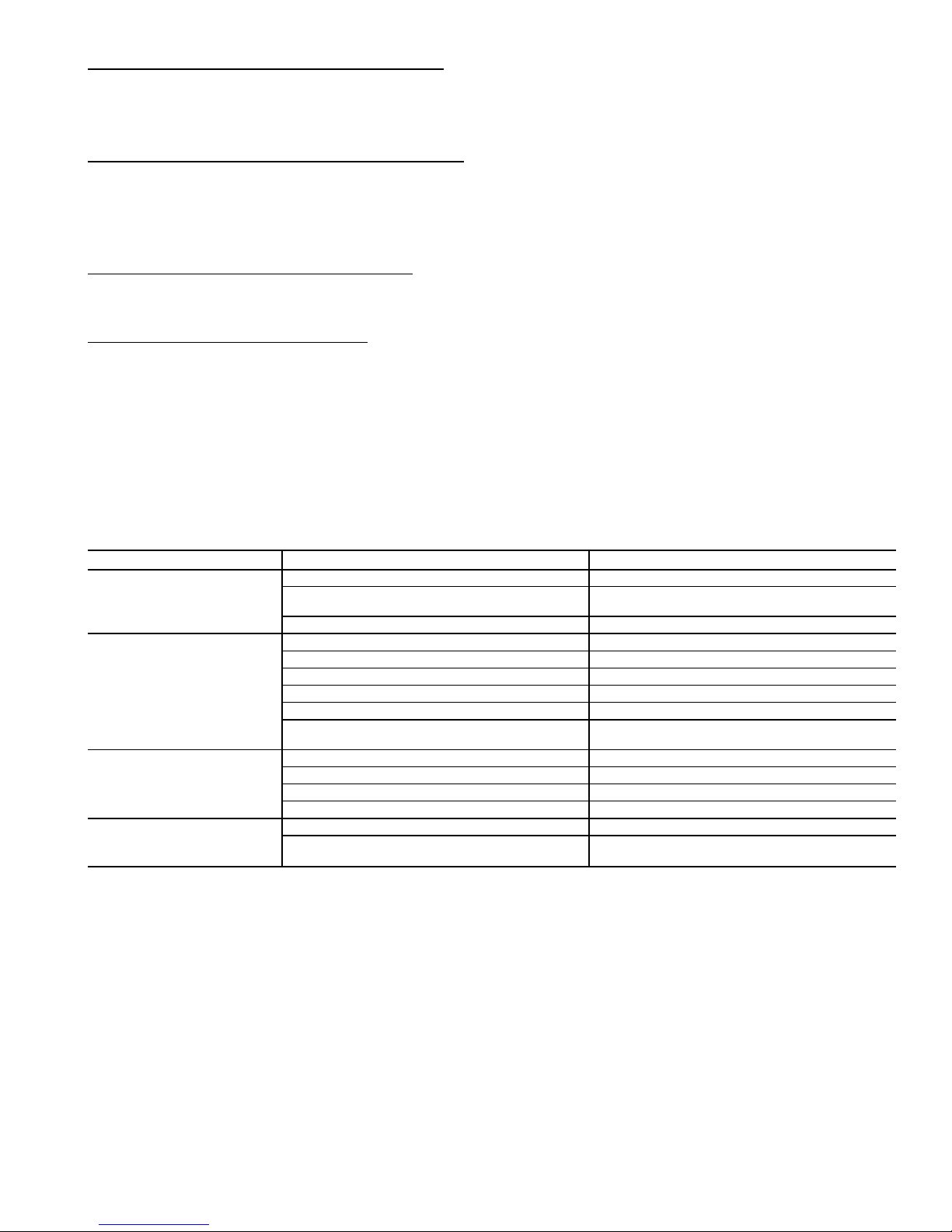
PROBLEM POTENTIAL SOURCE ACTION
Unit does not operate
Circuit breaker has tripped or fuse is blown Reset the circuit breaker or replace the fuse.
Power failure
Restart fan coil unit operation when power is
restored.
Voltage is too low Confirm the available voltage.
Insufficient Cooling
Air filter is blocked with dust Clean the air filter.
Temperature is not set properly Check and reset if necessary.
Window(s) and/or door(s) are open Close window(s) and door(s).
Outdoor unit is obstructed Remove the obstruction.
Fan speed is too low Change the fan speed
Operation mode is set to fan or auto. mode
Change to cooling operation or reset temperature
(using remote controller).
Insufficient Heating*
Air filter is blocked with dust Clean the air filter.
Temperature is not set properly Check and reset if necessary.
Window(s) and/or door(s) are open Close window(s) and door(s).
Outdoor unit is obstructed Remove the obstruction.
Unit stops during operation
Off timer is operating Turn off the off timer function.
Room temperature has reached the programmed
set point
Normal unit operation.
*Heat pump systems only.
15
Page 16
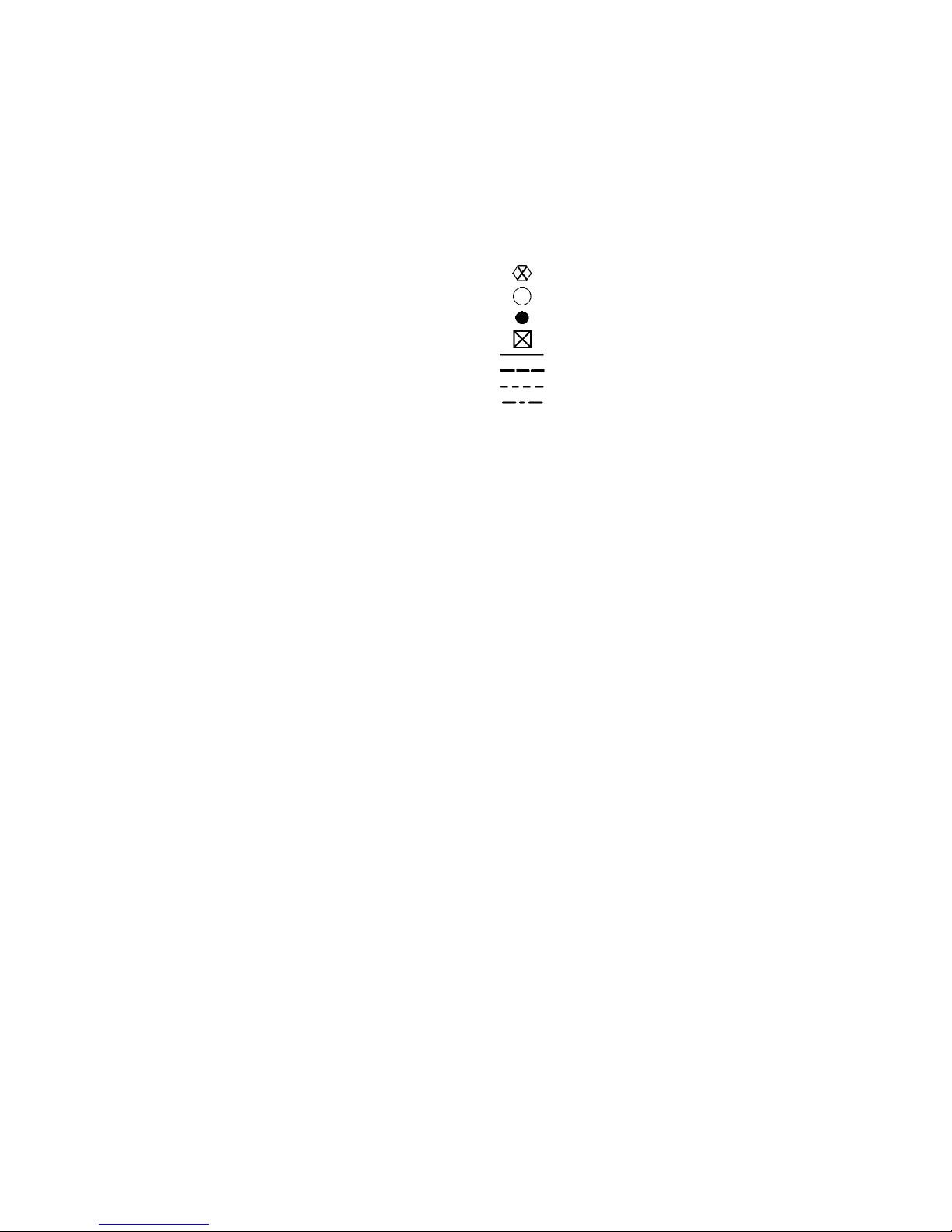
LEGEND AND NOTES FOR FIG. 24 AND 25
AGING — For the Burn-In Test
(short terminals)
AS — Assembly
C—Contactor
CAP — Capacitor
CH — Crankcase Heater
CLO — Compressor Lockout
CN — Connector
COMP — Compressor
CT — Current Transformer
DFB — Defrost Board
DFT — Defrost Thermostat
EQUIP GND — Equipment Ground
FMC — Fan Motor Capacitor
GND — Ground
HA — Home Automation
HPS — High-Pressure Switch
IDC TH — Indoor-Coil Thermistor
IDFM — Indoor Fan Motor
JEM-A — Japan Electric Manufacturing
Industry Association
LLPS — Liquid Low Pressure Switch
LPS — Low-Pressure Switch
OAC TH — Outdoor Coil Thermistor
ODA TH — Outdoor-Air Thermistor
ODC TH — Outdoor-Coil Thermistor
OFM — Outdoor Fan Motor
OFR — Outdoor Fan Relay
OL — Overload
PCB — Printed Circuit Board
RA TH — Return Air Thermistor
RC — Resistor Capacitor
RCV — Receiver
RVS — Reversing Valve Solenoid
SC — Start Capacitor
SR — Start Relay
STM — Step Motor
TB — Terminal Block
TRAN — Transformer
U—Unloader
Terminal (Marked)
Terminal (Unmarked)
Splice
Terminal Block
Factory Wiring
Field Control Wiring
Field Power Wiring
Accessory or Optional Wiring
1. If any of the original wire furnished must be replaced, it must be
replaced with type 90 C wire or its equivalent.
2. Wire in accordance with National Electrical Code (NEC) and local
codes.
3. The CLO locks out the compressor to prevent short cycling on compressor overloads and safety devices. Before replacing CLO, check
these other devices. A minimum 1 amp turn is required to hold
contacts closed.
4. A 24-ft long thermistor wiring cable is provided with the fan coil
unit.
5. Compressor and fan motors are protected by internal thermal overloads.
6. Transformer has an internal 2 amp thermal fuse on the primary
side.
16
Page 17
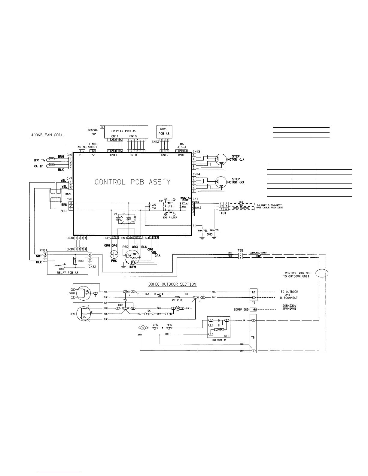
Fig. 24 — Cooling-Only System (38HDC Shown)
RELAY CHART
COMPRESSOR K13
THERMISTOR EQUIVALENCE
TEMPERATURE RESISTANCE
°F °C V
95 35 6,500
72 22 11,400
32 0 32,500
ALL THERMISTORS IN THE 40QN SYSTEMS ARE
IDENTICAL TO EACH OTHER
17
Page 18
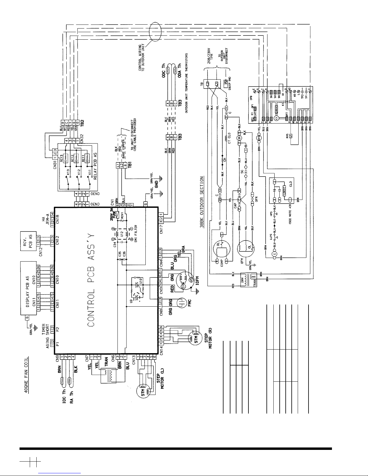
Fig. 25 — Heat Pump System
RELAY CHART
COMPRESSOR K13
REV. VALVE K11
OUTDOOR FAN K12
THERMISTOR EQUIVALENCE
TEMPERATURE RESISTANCE
°F °C V
95 35 6,500
72 22 11,400
32 0 32,500
ALL THERMISTORS IN THE 40QN SYSTEMS ARE
IDENTICAL TO EACH OTHER
Copyright 1996 Carrier Corporation
Manufacturer reserves the right to discontinue, or change at any time, specifications or designs without notice and without incurring obligations.
Book 1 4
Tab 3e 2f
PC 111 Catalog No. 534-078 Printed in U.S.A. Form 40QN-1SI Pg 18 4-96 Replaces: New
Page 19
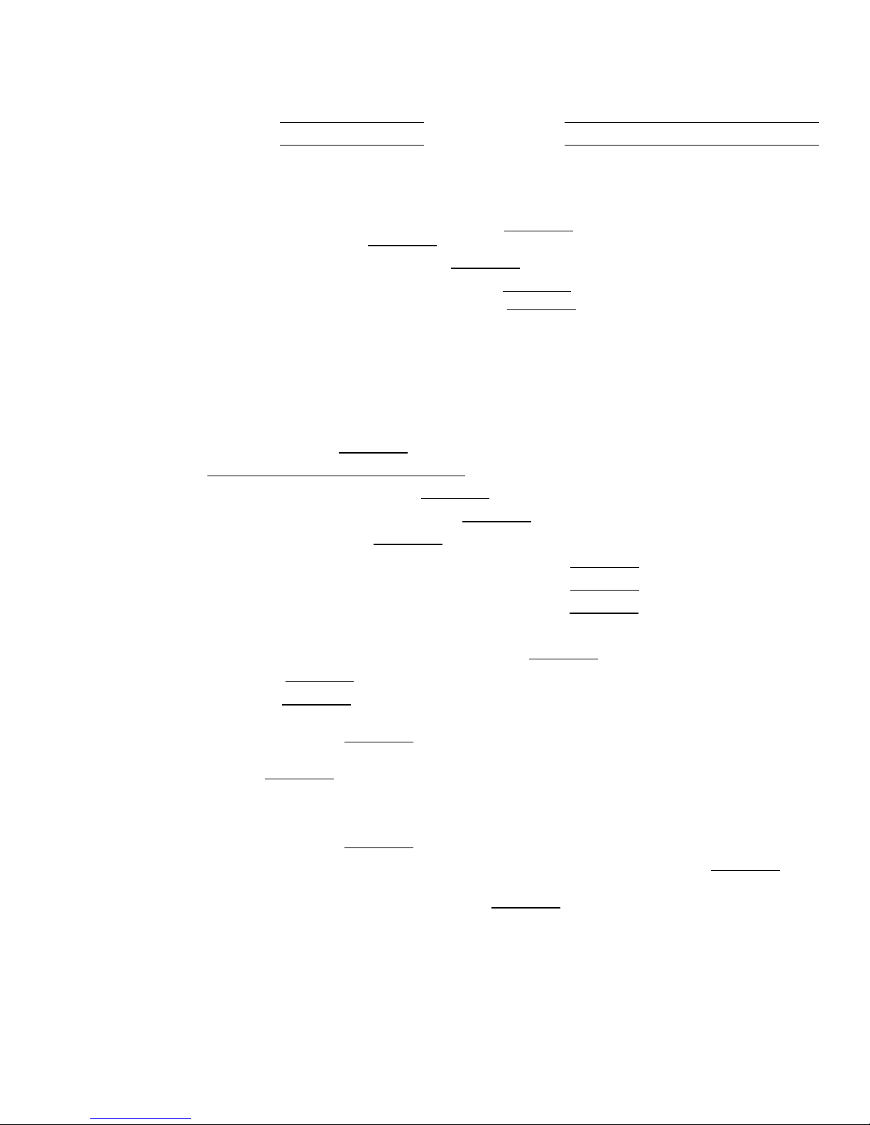
START-UP CHECKLIST
I. PRELIMINARY INFORMATION
OUTDOOR UNIT: MODEL NO.
OUTDOOR UNIT: MODEL NO.
SERIAL NO.
SERIAL NO.
ACCESSORIES: __________________________________________________________________________________
PISTONS (38HDC and 38BK SYSTEMS ONLY): INDOOR SIZE:
OUTDOOR SIZE (38BK SYSTEMS ONLY):
REFRIGERANT PIPING: EQUIVALENT LINE LENGTH: (IF OVER 50 FT)*
LIFT: FAN COIL ABOVE OUTDOOR UNIT (IF OVER 25 FT)*?
FAN COIL BELOW OUTDOOR UNIT (IF OVER 25 FT)*?
*APPLIES ONLY TO 38HDC AND 38BK UNITS USING LONG-LINES APPLICATIONS. MAXIMUM EQUIVALENT
LINE LENGTH FOR 38HDS SYSTEMS IS 50 FT. MAXIMUM LIFT ON 38HDS APPLICATIONS IS 30 FT FROM
LOWEST SYSTEM POINT TO HIGHEST SYSTEM POINT.
PRE-START-UP
INDOOR UNIT (REFER TO OUTDOOR UNIT INSTALLATION INSTRUCTIONS FOR OUTDOOR UNIT
PRE-START-UP FUNCTIONS)
IS THERE ANY SHIPPING DAMAGE?
IF YES, WHERE?
WILL THIS DAMAGE PREVENT UNIT START-UP?
CHECK POWER SUPPLY. IS IT 208/230, SINGLE PHASE?
HAS GROUND WIRE BEEN CONNECTED?
HAS THE CORRECT SIZE FUSE OR HACR BREAKER BEEN PROVIDED?
ARE POWER WIRES TO THE UNIT SIZED AND INSTALLED PROPERLY?
IS THE DISCONNECT SWITCH INSTALLED IN SIGHT FROM THE UNIT?
IS THE LOW-VOLTAGE CABLE (INDOOR TO OUTDOOR UNIT) RUN AND CONNECTED PROPERLY?
HAS CONDENSATE DRAIN BEEN RUN AND SLOPED PROPERLY?
IS AIR FILTER(S) IN PLACE?
IS UNIT MOUNTED LEVEL?
IS COOLING PISTON INSTALLED, THE CORRECT SIZE, AND IN THE CORRECT DIRECTION
(38HDC AND 38BK SYSTEMS ONLY)?
IS HEATING PISTON INSTALLED, THE CORRECT SIZE, AND IN THE CORRECT DIRECTION
(38BK SYSTEMS ONLY)?
PIPING
IS A LIQUID LINE SOLENOID INSTALLED IF REQUIRED BY LONG-LINE APPLICATIONS
(38HDC AND 38BK SYSTEMS ONLY)?
IS FILTER DRIER INSTALLED AT THE OUTDOOR UNIT (38HDC AND 38BK SYSTEMS ONLY)?
HAVE LEAK CHECKS BEEN MADE AT THE COMPRESSOR, OUTDOOR UNIT, FLARE CONNECTIONS, FILTER
DRIERS, AND FUSIBLE PLUGS WITH A LEAK DETECTOR?†
†FIELD PIPING AND ALL TUBING CONNECTIONS MUST BE LEAK TESTED BY THE PRESSURE METHOD DE-
SCRIBED IN CARRIER GENERAL TRAINING FOR AIR CONDITIONING MANUAL (GTAC2), MODULE 5. USE
R-22 AT APPROXIMATELY 25 PSIG BACKED UP WITH AN INERT GAS TO REACH A TOTAL SYSTEM PRESSURE
NOT TO EXCEED 245 PSIG.
CL-1
Page 20
START-UP CHECKLIST (cont)
HAS PIPING SYSTEM BEEN EVACUATED TO 1000 MICRONS (IF REQUIRED)?
HAS SYSTEM CHARGE BEEN WEIGHED IN (IF REQUIRED)?
HAVE SERVICE VALVES BEEN FULLY BACKSEATED?
CHECK VOLTAGE: IS VOLTAGE WITHIN RANGE SHOWN FOR UNIT (WITH UNIT OPERATING)?
OUTDOOR INDOOR
START-UP
IF UNIT HAS A CRANKCASE HEATER, HAS IT BEEN ON FOR 24 HOURS?
MEASURE AND RECORD THE:
AIR ENTERING OUTDOOR UNIT:
F
AIR ENTERING INDOOR UNIT:
F
DISCHARGE LINE TEMPERATURE:
F
VAPOR LINE TEMPERATURE:
F
MEASURE AND RECORD THE:
VAPOR LINE PRESSURE:
PSIG
DISCHARGE PRESSURE:
PSIG
----------------------------------------------------------------------------------------
CUT ALONG DOTTED LINE CUT ALONG DOTTED LINE
Copyright 1996 Carrier Corporation
Manufacturer reserves the right to discontinue, or change at any time, specifications or designs without notice and without incurring obligations.
Book 1 4
Tab 3e 2f
PC 111 Catalog No. 534-078 Printed in U.S.A. Form 40QN-1SI Pg CL-2 4-96 Replaces: New
 Loading...