

Carrier 38AUZ*07 Series, 38AUD*12 Series, 38AUZ*08 Series, 38AUD*14 Series Installation, Start-up And Service Instructions Manual
Page 1

38AU
Air-Cooled Condensing Units
50 Hz
®
with Puron
(R-410A) Refrigerant
Sizes 07 - 14
Installation, Start-Up and
Service Instructions
CONTENTS
SAFETY CONSIDERATIONS . . . . . . . . . . . . . . . . . . . . . . . 1
INSTALLATION GUIDELINES. . . . . . . . . . . . . . . . . . . . . . . 2
INSTALLATION . . . . . . . . . . . . . . . . . . . . . . . . . . . . . . . . 9-19
Step 1 – Plan for Unit Location . . . . . . . . . . . . . . . . . . . 9
Step 2 – Complete Pre-Installation Checks. . . . . . . . . . 9
Step 3 – Prepare Unit Mounting Support . . . . . . . . . . 9
Step 4 – Rig and Mount the Unit . . . . . . . . . . . . . . . . . . 9
Step 5 – Complete Refrigerant Piping Connections
Step 6 – Install Accessories. . . . . . . . . . . . . . . . . . . . . . 14
Step 7 – Complete Electrical Connections . . . . . . . . . 14
PRE-START-UP . . . . . . . . . . . . . . . . . . . . . . . . . . . . . . . . 19
System Check . . . . . . . . . . . . . . . . . . . . . . . . . . . . . . . . . 19
Turn On Crankcase Heater . . . . . . . . . . . . . . . . . . . . . . 19
Preliminary Charge. . . . . . . . . . . . . . . . . . . . . . . . . . . . . 19
START-UP. . . . . . . . . . . . . . . . . . . . . . . . . . . . . . . . . . . . . 19 -25
38AU Units . . . . . . . . . . . . . . . . . . . . . . . . . . . . . . . . . . . 19
OPERATING SEQUENCE. . . . . . . . . . . . . . . . . . . . . . . . . . 26
Indoor (Supply) Fan . . . . . . . . . . . . . . . . . . . . . . . . . . . . 26
Cooling, Unit Without Economizer . . . . . . . . . . . . . . . . 26
Cooling, Unit With Economizer. . . . . . . . . . . . . . . . . . . 26
Heating . . . . . . . . . . . . . . . . . . . . . . . . . . . . . . . . . . . . . . . 26
ROUTINE SYSTEM MAINTENANCE. . . . . . . . . . . . . . . 26
Quarterly Inspection (and 30 days after initial start)
Seasonal Maintenance . . . . . . . . . . . . . . . . . . . . . . . . 26
SERVICE. . . . . . . . . . . . . . . . . . . . . . . . . . . . . . . . . . . . . .27 - 33
Refrigeration System . . . . . . . . . . . . . . . . . . . . . . . . . 27
Compressor Oil. . . . . . . . . . . . . . . . . . . . . . . . . . . . . . . . 27
Servicing Systems on Roofs with
Synthetic Materials. . . . . . . . . . . . . . . . . . . . . . . . . . . . . 27
Liquid Line Filter Drier . . . . . . . . . . . . . . . . . . . . . . . . . 27
Filed Refrigerant Access Ports . . . . . . . . . . . . . . . . . 27
Factory High-flow Access Ports . . . . . . . . . . . . . . . . 27
Comfort Alert Diagnostic Module. . . . . . . . . . . . . . . 28
Crankcase Heater . . . . . . . . . . . . . . . . . . . . . . . . . . . . . . 30
Compressor Protection. . . . . . . . . . . . . . . . . . . . . . . . . . 30
Low-Pressure Switches . . . . . . . . . . . . . . . . . . . . . . . . . 30
High-Pressure Switches. . . . . . . . . . . . . . . . . . . . . . . . . 30
Outdoor Fans. . . . . . . . . . . . . . . . . . . . . . . . . . . . . . . . . . 30
Lubrication . . . . . . . . . . . . . . . . . . . . . . . . . . . . . . . . . . . 30
NOVATION™ Coil Cleaning and Maintenance . . . . 33
. . 10
. . 26
Repairing NOVATION Condenser Tube Leaks . . . . 33
Replacing NOVATION Condenser Coil . . . . . . . . . . 33
Service Parts . . . . . . . . . . . . . . . . . . . . . . . . . . . . . . . 333
Fastener Torque Values . . . . . . . . . . . . . . . . . . . . . . . 333
TROUBLESHOOTING . . . . . . . . . . . . . . . . . . . . . . . . . 34 -35
APPENDIX A
Air Conditioner and Heat Pump with Puron
Quick Reference Guide . . . . . . . . . . . . . . . . . . . . . . . 36
APPENDIX B
Wiring Diagram List. . . . . . . . . . . . . . . . . . . . . . . . . 36
APPENDIX C
Motormaster Sensor Locations. . . . . . . . . . . . . . . . . 37
START-UP CHECKLIST . . . . . . . . . . . . . . . . . . . .CL-1, CL-2
®
–
SAFETY CONSIDERATIONS
Improper installation, adjustment, alteration, service,
maintenance, or use can cause explosion, fire, electrical shock
or other conditions which may cause personal injury or
property damage. Consult a qualified installer, service agency,
or your distributor or branch for information or assistance. The
qualified installer or agency must use factory-authorized kits or
accessories when modifying this product. Refer to the
individual instructions package
Follow all safety codes. Wear safety glasses and work gloves.
Use quenching cloths for brazing operations and have a fire
extinguisher available. Read these instructions thoroughly and
follow all warnings or cautions attached to the unit. Consult
local building codes for special requirements. In absence of
local codes, it is recommended that the (USA standard ANSI/
NFPA70, National Electrical Code (NEC), be followed.
It is important to recognize safety information. This is the
safety-alert symbol . When you see this symbol on the unit
and in instructions or manuals, be alert to the potential for
personal injury.
Understand the signal words DANGER, WARNING,
CAUTION, and NOTE. These words are used with the safetyalert symbol. DANGER identifies the most serious hazards
which will result in severe personal injury or death.
WARNING signifies hazards which could result in personal
injury or death. CAUTION is used to identify unsafe practices,
which may result in minor personal injury or product and
property damage. NOTE is used to highlight suggestions
which will result in enhanced installation, reliability, or
operation.
Page 2
ELECTRICAL SHOCK HAZARD
Failure to follow this warning could cause personal injury
or death.
Before performing service or maintenance operations on
unit, always turn off main power switch to unit and install
lockout tag. Unit may have more than one power switch.
UNIT OPERATION AND SAFETY HAZARD
Failure to follow this warning could cause personal injury,
death and/or equipment damage.
Puron® (R-410A) refrigerant systems operate at higher
pressures than standard R-22 systems. Do not use R-22
service equipment or components on Puron refrigerant
equipment.
PERSONAL INJURY AND ENVIRONMENTAL
HAZARD
Failure to follow this warning could cause personal injury
or death.
Relieve pressure and recover all refrigerant before system
repair or final unit disposal.
Wear safety glasses and gloves when handling refrigerants.
Keep torches and other ignition sources away from
refrigerants and oils.
CUT HAZARD
Failure to follow this caution may result in personal injury.
Sheet metal parts may have sharp edges or burrs. Use care
and wear appropriate protective clothing, safety glasses and
gloves when handling parts and servicing 38AU units.
INSTALLATION GUIDELINE
Replacement /Retrofit – R22 to Puron
Replacement/retrofit installations require change-out of
outdoor unit, metering device, and filter driers. Change-out of
indoor coil (evaporator) and interconnecting tubing is
recommended.
Existing evaporator coil – If the existing evaporator coil may
be re-used, check with the coil manufacturer to verify the coil
construction is suitable for operation with the higher pressures
of Puron
is compatible with R-410A, replace if necessary. The minimum
factory test pressure rating must be 1725 kPa (250 psig).
Existing coil will need to be purged with Nitrogen to remove as
much mineral oil as possible to eliminate cross contamination
of oils.
®
(R-410A). Also determine if the existing TXV valve
®
Acid test – If the existing system is being replaced because of a
compressor electrical failure, assume acid is in system. If
system is being replaced for any other reason, use an approved
acid test kit to determine acid level. If even low levels of acid
are detected, install a 100 percent activated alumina suctionline filter drier in addition to the replacement liquid-line filter
drier. Remove the suction line filter drier as soon as possible,
with a maximum of 72 hr of operation. Recommendation:
Install a ball valve in the liquid line at the filter drier location
when installing a suction filter in the suction line (to facilitate
evacuation of the system’s low side when suction filter-drier is
removed).
Installation –
1. Remove the existing evaporator coil or fan coil and install
the replacement coil when appropriate.
2. Drain oil from low points and traps in suction line tubing
(and hot gas bypass tubing if appropriate) and evaporator
if they were not replaced. Removing oil from evaporator
coil may require purging of the tubing with dry nitrogen.
3. Unless indoor unit is equipped with a Puron® approved
metering device, change the metering device to a thermal
expansion valve (TXV) designed for Puron® (R-410A).
4. Remove the existing outdoor unit. Install the new outdoor
unit according to these installation instructions.
5. Install a new field-supplied liquid-line filter drier at the
indoor coil just upstream of the TXV or fix orifice
metering device.
6. If a suction line fil.ter-drier is also to be installed, install
the suction line filter-drier immediately upstream of the
suction line service valve at the outdoor unit. Note the
recommendation above regarding use of ball valve in the
liquid line.
UNIT DAMAGE HAZARD
Failure to follow this caution may result in equipment
damage or improper operation.
Never install suction-line filter drier in the liquid-line of a
®
Puron
system.
7. If required, install a 100% activated alumina suction line
filter drier at the outdoor unit.
8. Evacuate and charge the system according to the
instructions in this installation manual.
9. Operate the system for 10 hr. Monitor the pressure drop
across the suction line filter drier. If pressure drop
exceeds 21kPa (3 psig), replace suction-line and
liquid-line filter driers. Be sure to purge system with dry
nitrogen and evacuate when replacing filter driers.
Continue to monitor the pressure drop across suction-line
filter drier. Repeat filter changes is necessary. Never leave
suction-line filter drier in system longer than 72 hr.
2
Page 3

UNIT
Standard
Weight
Corner
A
Corner
B
Corner
C
Corner
D
Center of Gravity Unit Height
lbs. kg. lbs. kg. lbs. kg. lbs. kg. lbs. kg. X Y Z H
38AUZ*07
328 149 128 58 68 31 62 28 70 32
21.00
[533.4]
19.00
[482.6]
13.00
[330.2]
42.36
[1076.0]
38AUZ*08
353 160 138 63 72 33 65 29 78 35
19.00
[482.6]
23.00
[584.2]
13.00
[330.2]
42.36
[1076.0]
38AUD*12
499 226 193 88 111 50 72 38 123 56
20.000
[508.0]
23.00
[584.2]
15.00
[381.0]
50.36
[1279.2]
38AUD*14
505 229 190 86 88 40 76 34 151 68
20.000
[508.0]
24.00
[609.6]
15.00
[381.0]
50.36
[1279.2]
Fig. 1 — 38AU*07-14 Unit Dimensions
3
Page 4
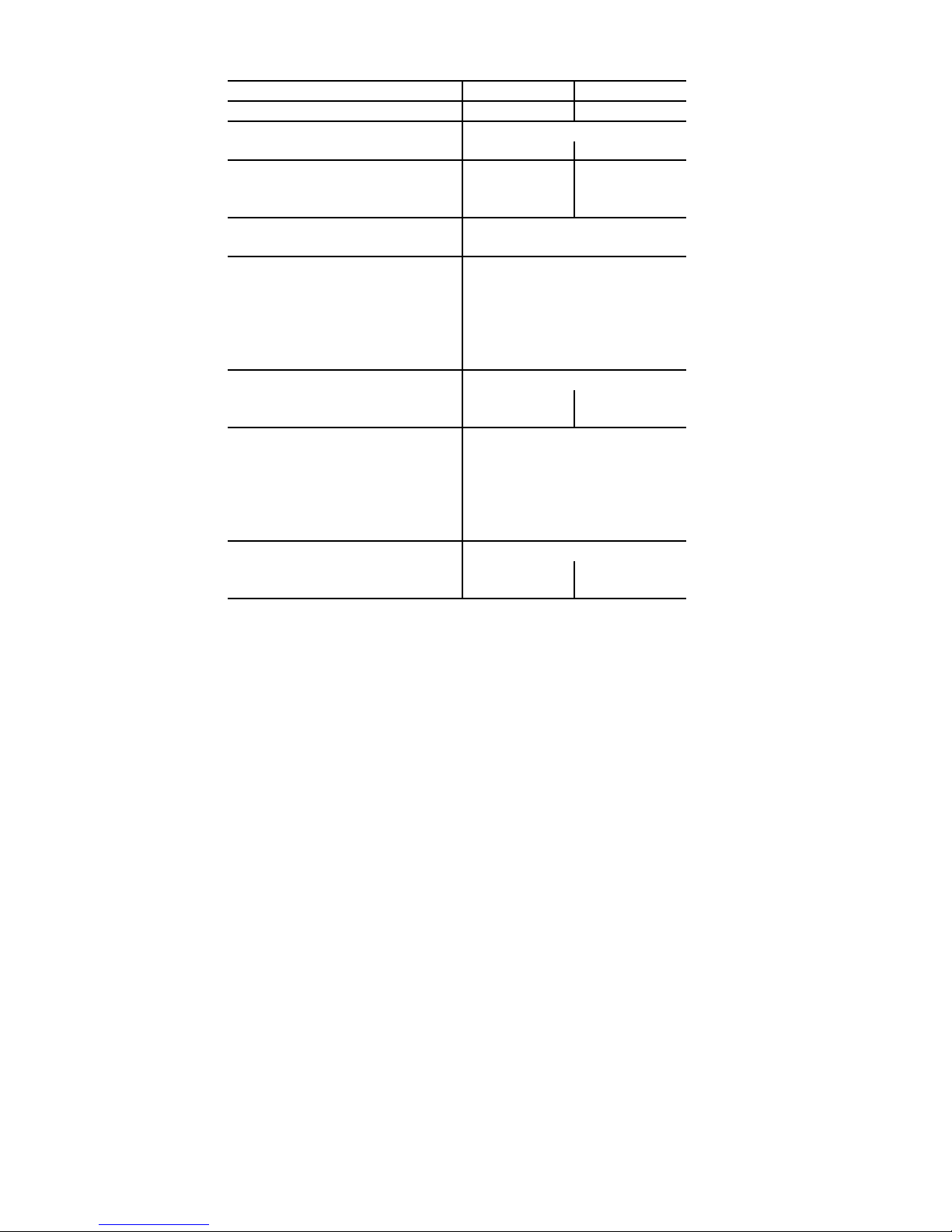
Table 1A — Physical Data — 38AUZ*07-08 Units — 50 Hz English
UNIT SIZE 38AU Z*07 Z*08
NOMINAL CAPACITY (tons)
OPERATING WEIGHTS (lb)
Aluminum-Fin Coils 328 353
REFRIGERANT TYPE
Operating Charge, Typical (lb)
‡
†
Shipping Charge (lb) 4.4 4.9
COMPRESSOR
Qty...Type 1...Scroll
OUTDOOR FANS
Qty...Rpm 2...1100
Motor Hp
Diameter 22
Nominal Airflow (Cfm Total) 6000
Watts (Total) 610
OUTDOOR COIL (Qty)
Face Area (sq ft total) 17.5 20.5
Rows/Fins per inch (FPI) 1/17 1/17
CONTROLS
Pressurestat Settings (psig)
High Cutout 630 ± 10
Cut-in 505 ± 20
Low Cutout 54 ± 3
Cut-in 117 ± 5
PIPING CONNECTIONS (in. ODS)
Qty...Suction 1...1
Qty...Liquid
67.5
R-410A
9.0 12.3
1
/
4
1...NOVATION
1
1...
/
8
3
/
8
1...11/
1...1/
8
2
LEGEND
ODS — Outside Diameter Sweat (socket)
‡ Unit is factory-supplied with partial charge only.
† Typical operating charge with 25 ft of interconnecting piping.
4
Page 5
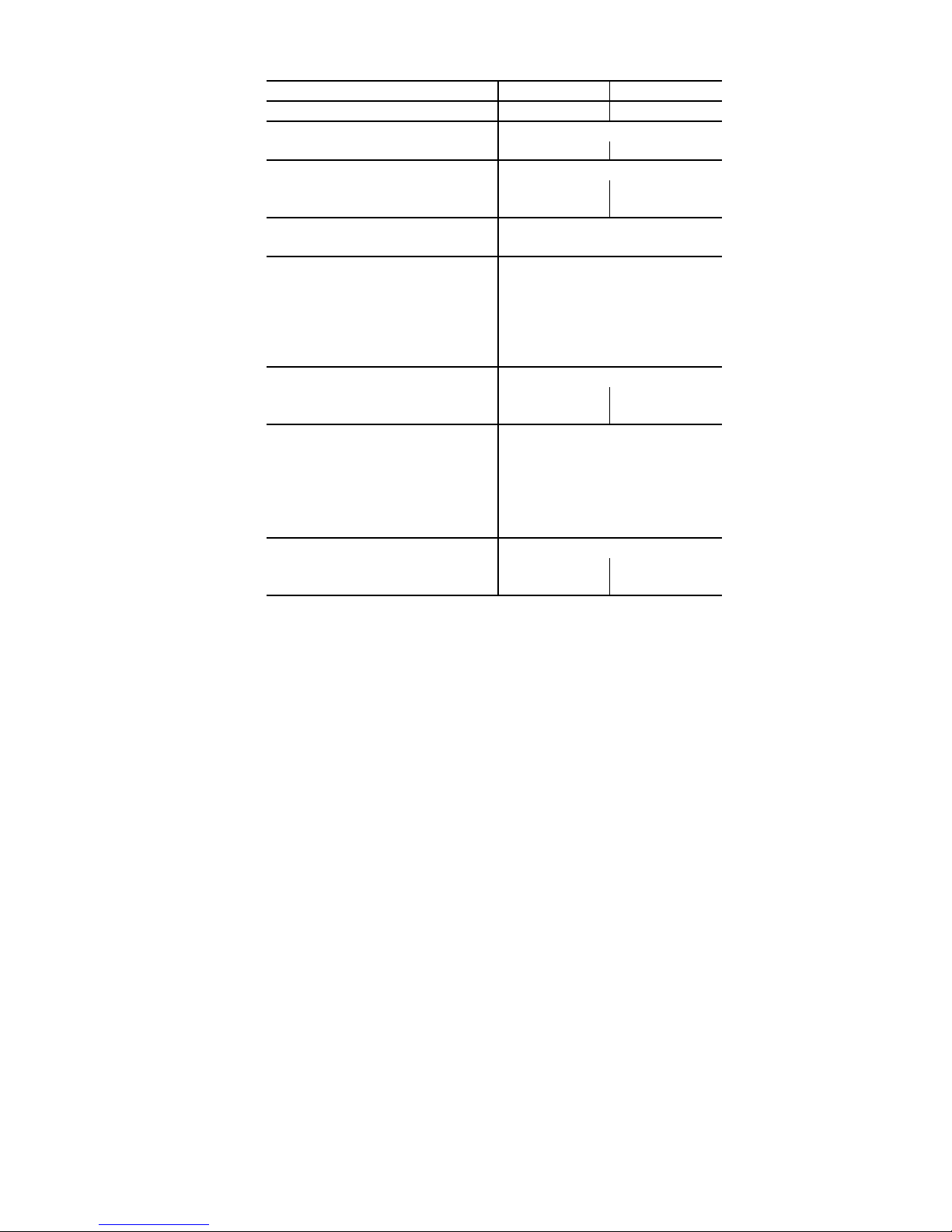
Table 1B — Physical Data — 38AUZ*07-08 Units — 50 Hz SI
UNIT SIZE 38AU Z*07 Z*08
NOMINAL CAPACITY (kW)
OPERATING WEIGHT (kg)
Aluminum-Fin Coils 149 160
REFRIGERANT TYPE
Operating Charge, Typical (kg)
‡
†
Shipping Charge (kg) 2.0 2.2
COMPRESSOR
Qty...Type 1...Scroll
OUTDOOR FANS
Qty...r/s 2...18
Motor Hp NEMA
Diameter (mm) 560
Nominal Airflow (L/s) 2832
Watts (Total) 610
OUTDOOR COIL (Qty)
Face Area (sq m total) 1.6 1.9
Rows/Fins per Meter (Fins/m) 1...670 1...670
CONTROLS
Pressurestat Settings (kPa)
High Cutout 4347 ± 70
Cut-in 3482 ±138
Low Cutout 372 ± 21
Cut-in 807 ± 34
PIPING CONNECTIONS (in. ODS)
Qty...Suction 1...1
Qty...Liquid
21.1 26.4
R-410A
4.1 5.6
1
/
4
1...NOVATION
1
1...
/
8
3
/
8
1...11/
1...1/
8
2
LEGEND
NEMA — National Electrical Manufacturers Association
ODS — Outside Diameter Sweat (socket)
‡ Unit is factory-supplied with partial charge only.
† Typical operating charge with 7.62 m of interconnecting piping.
5
Page 6
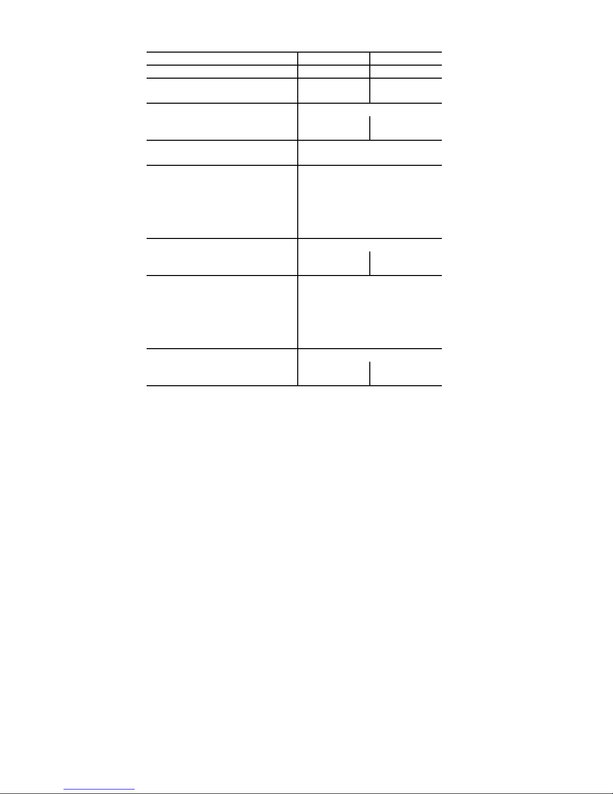
Table 2A — Physical Data — 38AUD*12-14 Units — 50 Hz English
UNIT SIZE 38AU D*12 D*14
NOMINAL CAPACITY (tons)
OPERATING WEIGHTS (lb)
Aluminum-Fin Coils 418 431
REFRIGERANT TYPE
Operating Charge A/B, Typical (lb)
‡
†
Shipping Charge A/B (lb) 3.0/3.1 3.7/3.9
COMPRESSOR
Qty...Type 2...Scroll
OUTDOOR FANS
Qty... RPM 2...1100
Motor Hp
Diameter (in) 22
Nominal Airflow (Cfm Total) 6,000
Watts (Total) 610
OUTDOOR COIL (Qty)
Face Area (sq ft total) 25.0 31.8
Rows/Fins per inch (FPI) 1/17 1/17
CONTROLS
Pressurestat Settings (psig)
High Cutout 630 ± 10
Cut-in 505 ± 20
Low Cutout 54 ± 3
Cut-in 117 ± 5
PIPING CONNECTIONS (in. ODS)
Qty...Suction A/B 1...1
Qty...Liquid A/B
10 12.5
R-410A
7.5/7.5 11.2/11.2
1
/4
1...NOVATION
1
1...
/8 /1...11/
3
/8 /1...3/
8
8
1...13/8 /1...13/
1...1/2 /1...1/
8
2
LEGEND
ODS — Outside Diameter Sweat (socket)
‡ Unit is factory-supplied with partial charge only.
† Typical operating charge with 25 ft of interconnecting piping.
6
Page 7
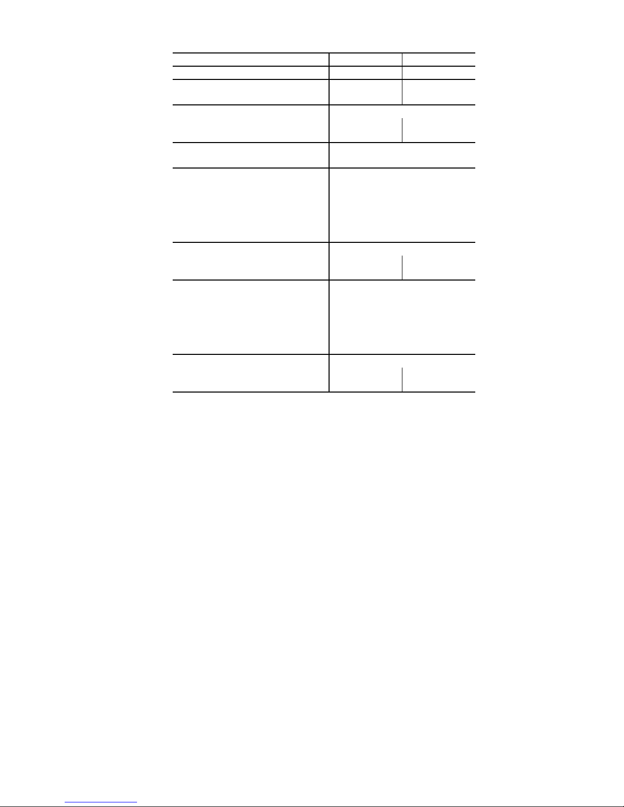
Table 2B — Physical Data — 38AUD*12-14 Units — 50 Hz SI
UNIT SIZE 38AU D*12 D*14
NOMINAL CAPACITY (kW)
OPERATING WEIGHT (kg)
Aluminum-Fin Coils 190 196
REFRIGERANT TYPE
Operating Charge A/B, Typical (kg)
‡
†
Shipping Charge A/B (kg) 1.3/1.4 1.7/1.8
COMPRESSOR
Qty...Model 2...Scroll
OUTDOOR FANS
Qty... r/s 2...18
Motor Hp NEMA
Diameter (mm) 560
Nominal Airflow (Cfm Total) 6,000
Watts (Total) 610
OUTDOOR COIL (Qty)
Face Area (sq m total) 2.3 3.0
Rows/Fins per Meter (Fins/m) 1...670 1...670
CONTROLS
Pressurestat Settings (kPa)
High Cutout 4347 ± 70
Cut-in 3482 ±138
Low Cutout 372 ± 21
Cut-in 807 ± 34
PIPING CONNECTIONS (in. ODS)
Qty...Suction A/B 1...1
Qty...Liquid A/B
35.1 44
R-410A
3.4/3.4 5.1/5.1
1
/
4
1...NOVATION
1
1...
/8 /1...11/
3
/8 /1...3/
8
8
1...13/8 /1...13/
1...1/2 /1...1/
8
2
LEGEND
NEMA — National Electrical Manufacturers Association
ODS — Outside Diameter Sweat (socket)
‡ Unit is factory-supplied with partial charge only.
† Typical operating charge with 7.62 m of interconnecting piping.
7
Page 8
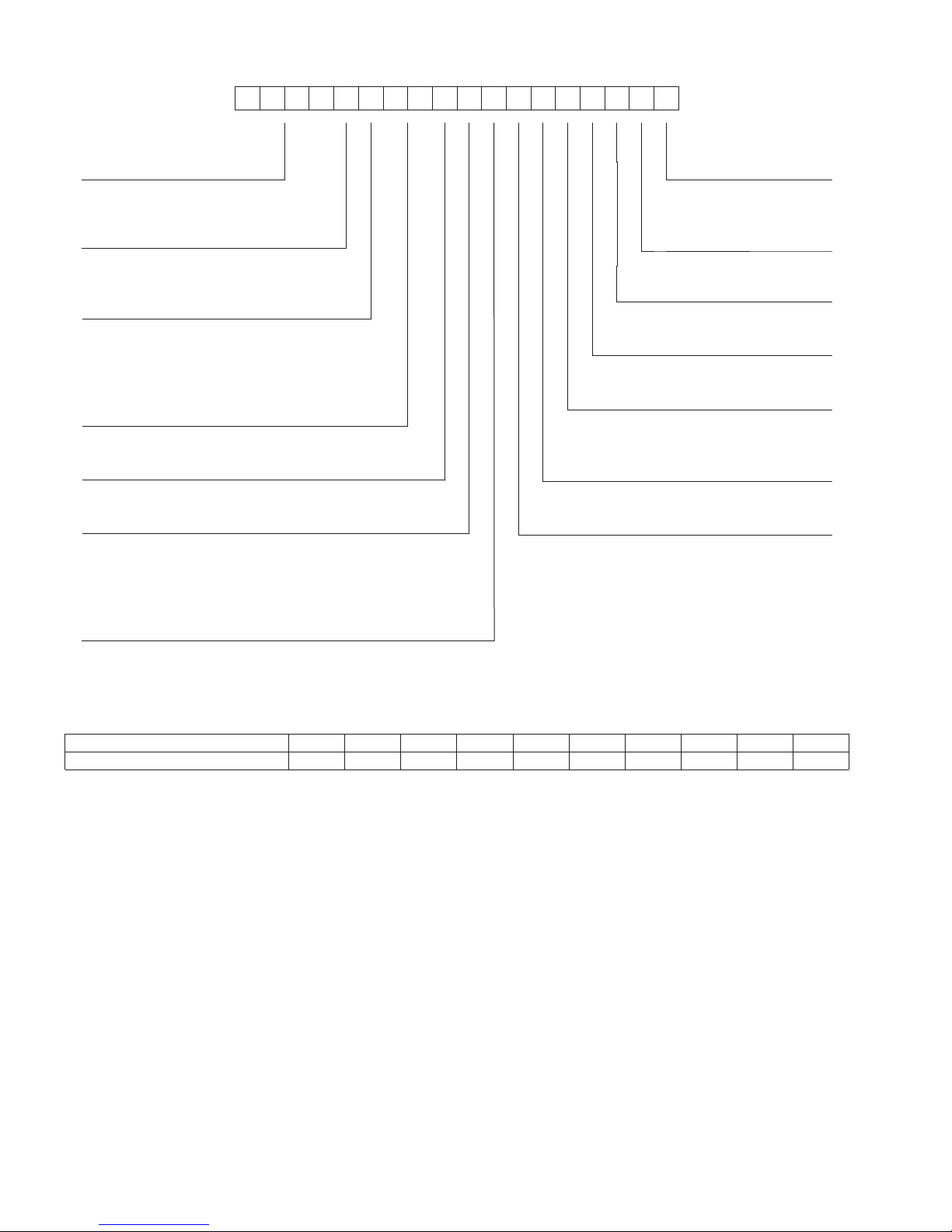
1 2 3 4 5 6 7 8 9 10 11 12 13 14 15 16 17 18
SETANGISEDNOITISOP
)radnelac lacsif( erutcafunam fo keeW1−2
)ASU ,saxeT ,PTE = G( noitacol gnirutcafunaM5
rebmun laitneuqeS6−10
12345678910
4609G12345
POSITION NUMBER
TYPICAL
Year of manufacture (”09” = 2009)3−4
38AUZA07A0G9–0A0A0
_____________ ____
Model Type Packaging
38AU= Carrier Condensing Unit
Puronr
R---410A Refrigerant
0=Standard
1=LTL
Type o f Co il
Z = Single Circuit, A/C Scroll Compressor
D = Dual Circuit, A/C Scroll Compressor
Refrigerant Options
A = None
B = Low Ambient
Nominal Tonnage
07 = 6 Tons
08 = 7.5 Tons
12 = 10 Tons
14 = 12.5 Tons
Factory Assigned
A=Default
Factory Assigned
0=Default
Coil Options (Condenser)
G = Al/Al Standard
K = E-Coated Al/Al
T = Al/Al with Louvered Hail Guard
W = E-Coated Al/Al with Louvered Hail Guard
Electrical Options
A=None
C = Non-Fused Disconnect
Service Options
1=
0=None
Factory Assigned
A = Default
Base Unit Controls
0 = Electro-Mechanical Controls
Design Rev
--- = Catalog Model Number
A = Initial Rev (Discrete Model Number)
Voltage
9 = 400/3/50
Fig. 2 — Model Number Nomenclature
Fig. 3 — Serial Number Nomenclature
8
Page 9

Matching 38AU Model To Evaporator Coil –
The Model 38AUZ is a single-circuit unit design, requiring one
set of refrigeration piping. This model can be connected to an
evaporator coil with one circuit or with two circuits (by manifolding the evaporator connections into a single piping system).
The Model 38AUD is a dual-circuit unit design that requires
two sets of refrigeration piping between the outdoor unit and
the evaporator coil (or coils). This model can only be connected to an evaporator coil that has two refrigeration circuits (or to
two separate evaporator coils). The Model 38AUD CANNOT
be connected to a single-circuit evaporator coil. The Model
38AUD CANNOT be field-converted to a single-circuit design.
Before unpacking this new 38AU model, compare the evaporator coil design to the 38AU model.
Table 3 — Evaporator Coil Connections
Evaporator Coil has Connect to Model Notes
Single Circuit 38AUZ ONLY
Manifold evaporator
circuits into single
piping system
Use two separate
piping systems
Two Circuits
38AUZ
Or
38AUD
INSTALLATION
Jobsite Survey
Complete the following checks before installation.
1. Consult local building codes or the U.S. A. National Electrical Code (Ref: ANSI/NFPA 70 [American National
Standards Institute/National Fire Protection Association],
latest version) for special installation requirements.
2. Determine unit location (from project plans) or select unit
location.
3. Check for possible overhead obstructions which may interfere with unit lifting or rigging.
Step 1 — Plan for Unit Location
Select a location for the unit and its support system (pad, rails
or other) that provides for the minimum clearances required for
safety. This includes minimum working space, clearances between live electrical components and nearest barriers (grounded or ungrounded), clearances for unit performance and service
access below, around and above unit as specified in unit drawings. See Fig. 4.
NOTE: Local codes may require different clearances than
specified in Fig. 4. It is the responsibility of installers to be
knowledgeable in local codes and to modify the recommended clearances to satisfy local codes.
NOTE: Consider also the effect of adjacent units on airflow
performance and control box safety clearance.
Do not install the outdoor unit in an area where fresh air supply
to the outdoor coil may be restricted or when recirculation from
the condenser fan discharge is possible. Do not locate the unit
in a well or next to high walls.
Evaluate the path and required line length for interconnecting
refrigeration piping, including suction riser requirements (outdoor unit above indoor unit), liquid line lift (outdoor unit below
indoor unit) and hot gas bypass line. Relocate sections to minimize the length of interconnecting tubing.
DO NOT BURY REFRIGERATION LINES.
Although unit is weatherproof, avoid locations that permit
water from higher level runoff and overhangs to fall onto the
unit.
RIGHT:
REAR:
Min 457 mm (18”)
requried for service
LEFT:
Min 457 mm (18”)
requried for service
Note: Observe requirements for 914 mm (39”) operating clearance
on either Left or Rear coil opening.
Fig. 4 — Service Clearance Dimensional Drawing
Min 457 mm (18”)
requried for service
FRONT:
1067 mm (42”)
Step 2 — Complete Pre-Installation Checks
CHECK UNIT ELECTRICAL CHARACTERISTIC —
Confirm before installation of unit that voltage, amperage and
circuit protection requirements listed on unit data plate agree
with power supply provided.
— UNCRATE UNIT — Remove unit packaging except for
the top skid assembly, which should be left in place until after
the unit is rigged into its final location.
INSPECT SHIPMENT — File a claim with shipping company if the shipment is damaged or incomplete.
CONSIDER SYSTEM REQUIREMENTS
• Consult local building codes and National Electrical
Code (NEC, U.S.A.) for special installation requirements.
• Allow sufficient space for airflow clearance, wiring,
refrigerant piping, and servicing unit. See Fig.1 for unit
dimensions and weight distribution data.
• Locate the unit so that the outdoor coil (condenser) airflow is unrestricted on all sides and above.
• The unit may be mounted on a level pad directly on the
base channels or mounted on raised pads at support
points. See Tables 1A through 2B for unit operating
weights. See Fig. 1 for weight distribution based on recommended support points.
NOTE: If vibration isolators are required for a particular
installation, use the data in Fig. 1 to make the proper
selection.
Step 3 — Prepare Unit Mounting Support
Slab Mount —
Provide a level concrete slab that extends a minimum of 150
mm (6 in.) beyond unit cabinet. Install a gravel apron in front
of condenser coil air inlet to prevent grass and foliage from
obstructing airflow.
Step 4 — Rig and Mount the Unit
UNIT DAMAGE HAZARD
Failure to follow this caution may result in equipment
damage.
All panels must be in place when rigging. Unit is not
designed for handling by fork truck.
RIGGING — These units are designed for overhead rigging.
Refer to the rigging label for preferred rigging method. Spreader bars are not required if top crating is left on the unit. All panels must be in place when rigging. As further protection for coil
9
Page 10

faces, plywood sheets may be placed against the sides of the
unit, behind cables. Run cables to a central suspension point so
that the angle from the horizontal is not less than 45 degrees.
Raise and set the unit down carefully.
If it is necessary to roll the unit into position, mount the unit on
longitudinal rails, using a minimum of 3 rollers. Apply force to
the rails, not the unit. If the unit is to be skidded into position,
place it on a large pad and drag it by the pad. Do not apply any
force to the unit.
Raise from above to lift the unit from the rails or pad when unit
is in its final position.
After the unit is in position, remove all shipping materials and
top crating.
Step 5 — Complete Refrigerant Piping
Connections
IMPORTANT: Do not bury refrigerant piping underground.
IMPORTANT: A refrigerant receiver is not provided with
the unit. Do not install a receiver.
PROVIDE SAFETY RELIEF — The 38AU unit is provided
with a fusible joint in the suction line in accordance with
applicable UL standards for pressure relief. If local codes
dictate an additional safety relief device, purchase locally and
install locally. Installation will require the recovery of the
factory shipping charge before the factory tubing can be cut
and the supplemental relief device is installed.
Model 38AUD has two separate refrigeration systems. If
required, each circuit will require a field-supplied/installed
supplemental relief device.
Table 4 — Equivalent Lengths for Common Fittings (ft)
Nominal
Tub e OD
3
/
8
1
/
2
5
/
8
3
/
4
7/
8
1
1
/
8
3
1
/
8
5
1
/
8
1
2
/
8
Nominal
Tub e OD
3
/
8
1
/
2
5
/
8
3
/
4
7/
8
1
1
/
8
3
1
/
8
5
1
/
8
1
2
/
8
90° Std 90° Lrad 90° Street 45° Std 45° Street
1.3 0.8 2.2 0.6 1
1.4 0.9 2.3 0.7 1.1
1.6 1 2.5 0.8 1.3
1.8 1.2 2.9 0.9 1.5
2 1.4 3.2 0.9 1.6
2.6 1.7 4.1 1.3 2.1
3.3 2.3 5.6 1.7 3
4 2.6 6.3 2.1 3.4
5 3.3 8.2 2.6 4.5
Branch
Flow
2.6 0.8 1.1 1.3
2.7 0.9 1.2 1.4
3.5 1.2 1.7 1.8
10 3.3 4.7 5
No Reduct Reduce 25% Reduce 50%
31 1.41.6
41.4 1.9 2
5 1.7 2.3 2.6
7 2.3 3.1 3.3
82.6 3.7 4
Elbows
Tees
Straight-Thru
CHECK 38AU MODEL WITH EVAPORATOR COIL CONNECTIONS — Confirm before installation of unit that the
evaporator coil connections are consistent with this 38AU
model. See Table 3 on page 9.
DETERMINE REFRIGERANT LINE SIZES — Select the
recommended line sizes for 38AUZ and 38AUD unit from the
appropriate tables.
Determine the linear length of interconnecting piping required
between the outdoor unit and indoor unit (evaporator).
Consider and identify also the arrangement of the tubing path
(quantity and type of elbows in both lines), liquid line solenoid
size, filter drier and any other refrigeration specialties located
in the liquid line. Refer to the indoor unit installation
instructions for additional details on refrigeration specialties
devices.
Determine equivalent line length adjustments for path and
components and add to linear line lengths. See Table 4,
Equivalent Lengths for Common Fittings, for usual fitting
types. Also identify adjustments for refrigeration specialties.
Refer to Part 3 of the Carrier System Design Manual for
additional data and information on equivalent lengths.
NOTE: Equivalent line lengths will vary based on tube
diameter. Calculate equivalent line length for each pipe by
adding equivalent length adjustments to linear lengths for
each pipe.
Enter the appropriate table to select the recommended line
sizes.
Model: Line Sizes Table Quantity of Line Sets
38AUZ 5 1
38AUD 6 2
Liquid Lift – A liquid lift condition exists when the outdoor
unit is located below the indoor (evaporator) unit and liquid
flows vertically up in a portion of the liquid line. The vertical
column of liquid reduces the available state point subcooling at
the evaporator coil’s thermal expansion valve. This effect
reduces the length of liquid lift (feet of elevation) that a liquid
line size can accommodate. Longer linear tube lengths will also
reduce the amount of liquid lift possible.
Check Tables 5 (38AUZ) and 6 (38AUD) for maximum liquid
lift capabilities for line sizes. Reselect the liquid line tube size if
necessary. If maximum available tube size cannot provide the
required lift distance on this installation, relocate the outdoor
unit to reduce the equivalent line length or the lift requirement.
Suction Riser – A suction riser condition exists when the
outdoor unit is located above the indoor (evaporator) unit and
suction vapor must flow vertically up to return to the
compressor. Oil return is a concern when the suction tube size
is too large to produce the minimum refrigerant velocity to
ensure oil return at minimum load conditions.
Check Table 7 for maximum suction tube size for 38AU units
at minimum load conditions. Consider suction speed riser
(reduced tube size for vertical segment only) or double suction
riser arrangement if the recommended suction tube size does
not provide necessary minimum flowrates for this riser.
10
Page 11
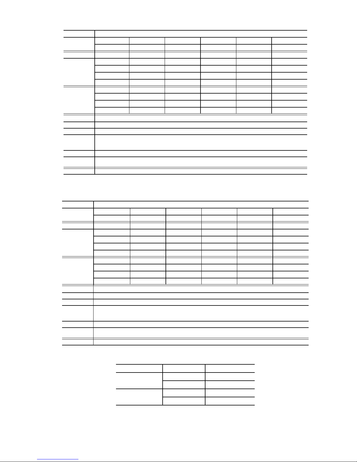
Table 5 — 38AUZ 07-08 Piping Recommendations (Single-Circuit Unit)
R-410A Equivalent Length
Ft 0-38 38-75 75-113 113-150 150-188
m 0-12 12-23 23-34 34-46 46-57
Model Typ Linear ft 0-25 25-50 50-75 75-100 100-125
38AUZ*07 Liquid Line
3
/
8
3
1
/
8
1
/
/
2
2
1
5
/
2
1
/
8
5
/
/
2
8
Max Lift 25 42 50 75 90 100 86 101
Suction Line
7
/
1-1/
8
7
/
8
1-1/81-1/
8
8
1-1/
8
1-1/
8
Charge (lbs) 8.4 9.6 11.1 13.1 15.0 18.8 16.9 22.6
38AUZ*08 Liquid Line
1
/
2
1
/
2
1
/
2
1
/
2
1
/
2
Max Lift 25 50 75 100 112
Suction Line
8
1-1/81-1/
8
1-1/
8
1-1/
8
1-1/
8
7
/
Charge (lbs) 11.8 9.6 12.9 16.8 18.7
Legend:
Length Equiv Equivalent tubing length, including effects of refrigeration specialties devices
Liquid Line Tubing size, inches OD.
Max Lift
Cooling
Heating
Suction Line Tube size, inches OD
Charge Charge Quantity, lbs. Calculated for both liquid line sizes (where applicable), but only with larger suction line size (where
NOTE:
Maximum liquid lift at maximum permitted liquid line pressure drop
• Indoor unit ABOVE outdoor unit
• Indoor unit BELOW outdoor unit
applicable)
For applications with linear length greater than 100 ft (30.5 m), contact your local Carrier representative.
Table 6 — 38AUD 12-14 Piping Recommendations (Two-Circuit Unit)
NOTE: 38AUD requires TWO sets of refrigeration piping
R-410A Equivalent Length
Ft 0-38 38-75 75-113 113-150 150-188
m 0-12 12-23 23-34 34-46 46-57
Model Typ Linear ft 0-25 25-50 50-75 75-100 100-125
38AUD*12 Liquid Line
3
/
8
3
/
8
3
1
/
8
1
/
/
2
2
1
/
2
Max Lift 25 50 28 75 100 99
Suction Line
7
/
8
7
/
8
11/
8
11/
8
11/
8
Charge ea. (lbs) 7.1 8.1 9.6 11.9 13.8 15.8
38AUD*14 Liquid Line
3
/
8
3
/
8
3
1
/
8
1
/
/
2
2
1
/
2
Max Lift 25 50 48 75 100 122
Suction Line
7
/
8
7
/
8
11/
8
11/
8
11/
8
Charge ea. (lbs) 9.7 10.7 12.2 14.5 16.4 18.4
Legend:
Length Equiv Equivalent tubing length, including effects of refrigeration specialties devices
Liquid Line Tubing size, inches OD.
Max Lift
Cooling
Heating
Suction Line Tube size, inches OD
Charge Charge Quantity, lbs. Calculated for both liquid line sizes (where applicable), but only with larger suction line size (where
NOTE:
Maximum liquid lift at maximum permitted liquid line pressure drop
• Indoor unit ABOVE outdoor unit
• Indoor unit BELOW outdoor unit
applicable)
For applications with linear length greater than 100 ft (30.5 m), contact your local Carrier representative.
Table 7 — 38AU Maximum Suction Pipe Size
Model: Unit Size Maximum Tube Size
3
38AUZ 07 1
08 15/
38AUD 12 13/
14 15/
/
8
8
8
8
11
Page 12
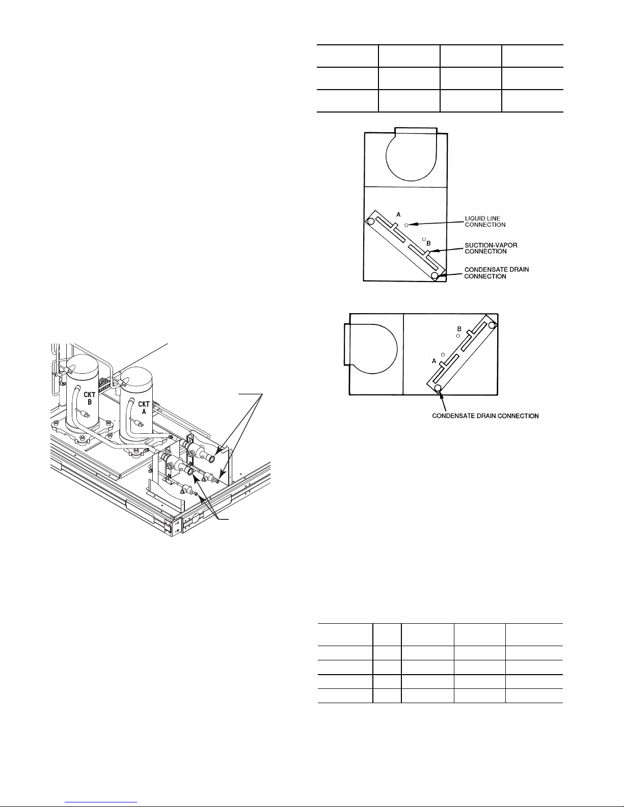
INSULATE SUCTION LINES — Apply closed-cell tubular
Circuit A
Connections
Circuit B
Connections
FIRST ON/LA ST OFF = B
VERTICAL INSTALLATION
FIRS T ON/LAST OF F = A
HORIZONTAL INSTALLATION
insulation to all suction lines between evaporator coil
connection and 38AU unit’s suction service valve.
Hot Gas Bypass – Hot gas bypass, if used, should be
introduced before the evaporator. (A bypass route that also
bypasses the evaporator circuit may lead to oil trapping in the
evaporator circuit during low load conditions and then to oil
slugging as evaporator load increases.) Model 38AU units do
not include a hot gas stub connection; a tee must be fieldsupplied and installed in the compressor discharge line. Run a
½-in OD line between outdoor unit and evaporator coil inlet.
Install an Auxiliary Side Connector at the evaporator between
TXV and distributor (follow instructions for the side connector
part). Insulate the hot gas line.
38AUD: Generally only one hot gas bypass system will be
applied on a two-circuit unit. Connect the hot gas bypass
system to Circuit A (first-on/last-off, connected to the
evaporator coil’s bottom circuit).
38AUD PIPING CONNECTIONS – The 38AUD’s two
circuits are designated Circuit A and Circuit B. Circuit A is
controlled by the thermostat’s Y1 (or TC1) contact and will be
the first circuit on and last circuit off. Circuit B is controlled by
the thermostat’s Y2 (or TC2) contact and this circuit is always
the “lag” circuit.
See Fig. 5 for location of the Circuit A and Circuit B service
valves and field piping connections. Circuit A is on the righthand side of the service valve compartment; Circuit B is on the
left.
40RU
Arrangement
Vertical
Horizontal
Cooling
Stage
Y1
Y2
Y1
Y2
40RU Coil
Segment
B
A
A
B
Connect to
38AUD
Circuit A
Circuit B
Circuit A
Circuit B
Fig 5 - 38AUD Service Valve Locations
When a single piece evaporator coil with two separate circuits
is connected to a 38AUD, the lower coil circuit should be
connected to the 38AUD’s Circuit A so that the evaporator’s
lower coil segment is first-on/last-off (to avoid re-evaporation
of condensate on dry lower coil segments).
Plan the Circuit A and Circuit B tubing segments carefully,
mark each segment and check constantly as piping systems are
assembled to avoid piping errors.
38AUD unit cannot be field-piped as a single-circuit/tandem
system.
Connecting 40RU to 38AUD – The 40RU fan coil in sizes 12,
14 and 16 is a face-split coil design that also has its circuits
designated as A and B. See Fig. 6. Note that the lower coil
segment changes as the arrangement of the 40RU changes. In a
vertical arrangement, the 40RU’s lower coil segment is
segment B; this segment should be connected to the 38AUD’s
Circuit A. In a horizontal arrangement, the 40RU’s lower
segment is now segment A; this segment should be connected
to the 38AUD’s Circuit A.
Fig. 6 — Typical Evaporator Coil Connections (40RU)
Note that refrigerant suction piping should be insulated.
INSTALL FILTER DRIER(S) AND MOISTURE
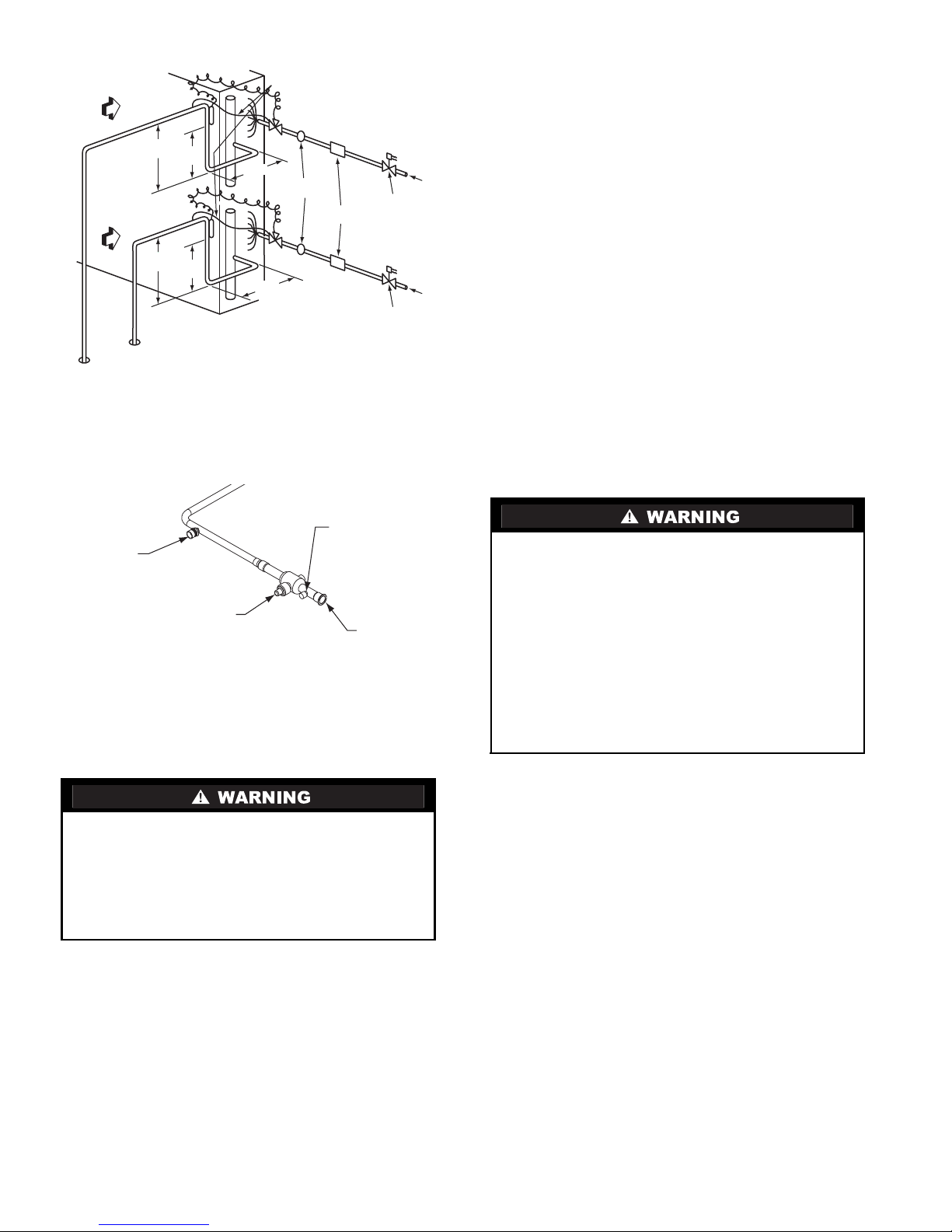
INDICATOR(S) — Every unit MUST have a filter drier in the
liquid line. 38AUD models require two filter driers (one in
each liquid line). Locate the filter drier(s) at the indoor unit,
close to the evaporator coil’s thermal expansion valve (TXV)
inlets.
38AU units include one (38AUZ) or two (38AUD) Puron-duty
filter drier(s), shipped in cartons attached to the unit basepan.
Remove the filter drier(s) and prepare to install in the liquid
line(s) at the evaporator coil. Do not remove connection fitting
plugs until ready to connect and braze the filter drier into the
liquid line position.
Table 8 — Puron-duty Filter Drier(s)
Model-Size Qty
38AUZ*07 1
38AUZ*08 1
38AUD*12 2
38AUD*14 2
Liquid
Line OD
3
/8-in 8 cu. in. KH43LG091
1
/2-in 16 cu. in. KH43LG085
3
/8-in 8 cu. in. KH43LG091
1
/2-in 16 cu. in. KH43LG085
Desiccant
Vol ume
Part
Number Ref
Installation of liquid line moisture indicating sightglass in each
circuit is recommended. Locate the sightglass(es) between the
outlet of the filter drier and the TXV inlet.
12
Page 13
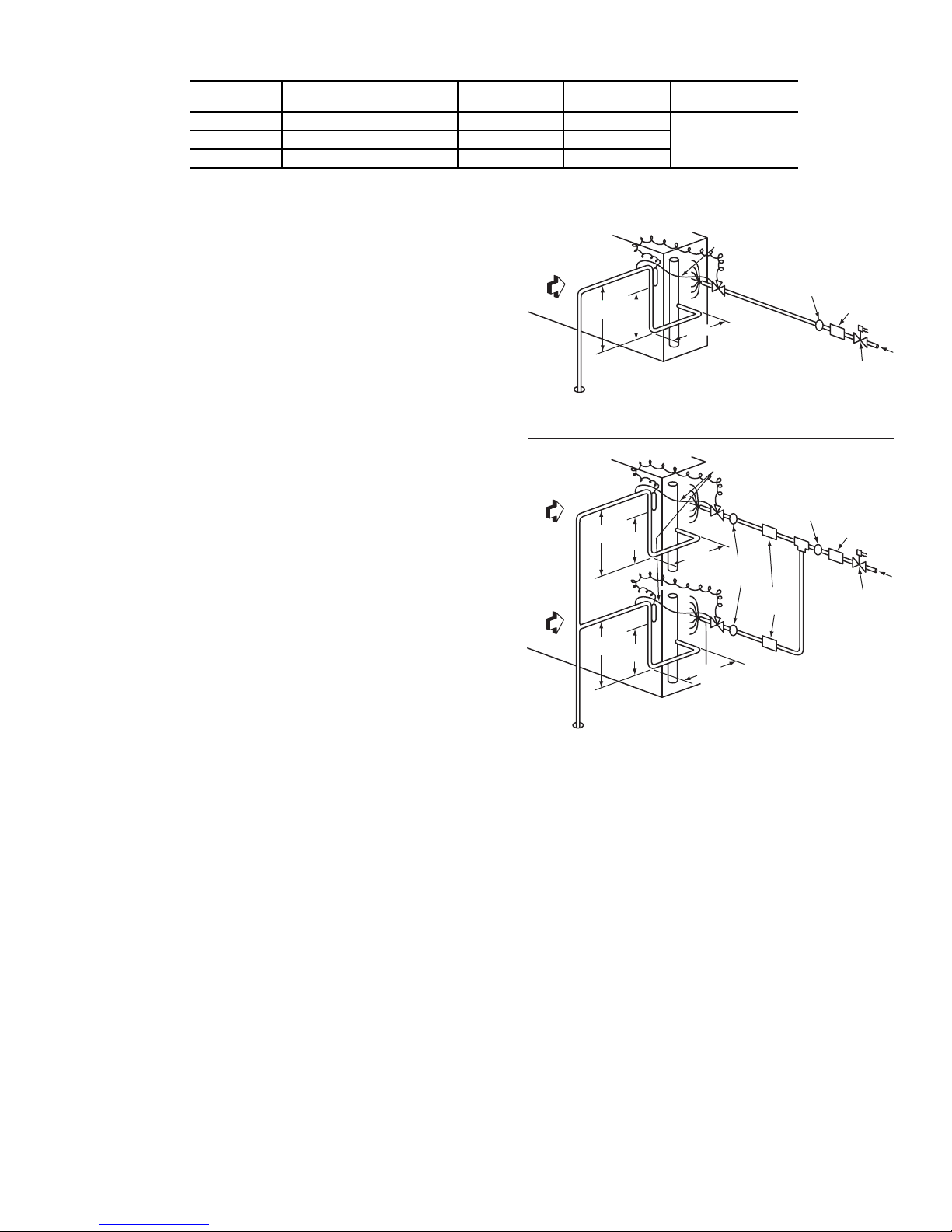
Table 9 — Refrigerant Specialities Part Numbers.
LEGEND
TXV — Thermostatic Expansion Valve
LIQUID LINE
SIZE (in.)
3
/
8
1
/
2
5
/
8
LIQUID LINE
SOLENOID VALVE (LLSV)
ALC-066208 AMG-24/50-60 HMI-1TT3
ALC-066209 AMG-24/50-60 HMI-1TT4
ALC-066212 AMG-24/50-60 HMI-1TT5
38AUD units require TWO sets of parts.
Refer to Table 9 for recommendations on refrigeration
specialties.
In some applications, depending on space and convenience requirements, it may be desirable to install 2 filter driers and sight
glasses in a single circuit application. One filter drier and sight
glass may be installed at A locations in Fig. 7, or 2 filter driers
and sight glasses may be installed at B locations.
Select the filter drier for maximum unit capacity and minimum
pressure drop. Complete the refrigerant piping from the indoor
unit to the outdoor unit before opening the liquid and suction
lines at the outdoor unit.
INSTALL LIQUID LINE SOLENOID VALVE —
It is recommended that a solenoid valve be placed in the main
liquid line (see Fig. 7) between the condensing unit and the
evaporator coil. Locate the solenoid valve at the outlet end of
the liquid line, near the evaporator coil connections, with flow
direction arrow pointed at the evaporator coil. Refer to Table 9.
(A liquid line solenoid valve is required when the liquid line
length exceeds 23 m [75 ft].) This valve prevents refrigerant
migration (which causes oil dilution) to the compressor during
the off cycle, at low outdoor ambient temperatures. Wire the
solenoid in parallel with the compressor contactor coil (see
Fig. 7). This means of electrical control is referred to as solenoid drop control.
CAPACITY CONTROL LIQUID LINE SOLENOID VALVE
Evaporator capacity control via liquid solenoid valve is not recommended for use with 38AU models.
MAKE PIPING CONNECTIONS — Piping connections at
the 38AU unit are ball valves with stub tube extensions. Do not
open the unit service valves until all interconnecting tube brazing as been completed.
The stub tube connections include ¼-in SAE service fittings
with Schrader valve cores (see Fig. 9). Before making any
brazed connections to the unit service valves, remove both
Schrader valve caps and cores and save for re-installation. Connect a source for nitrogen to one of these service fittings during
tube brazing to prevent the formation of copper oxides inside
the tubes at brazed joints.
When connecting the field tubing to the 38AU service valves,
wrap the valves in wet rags to prevent overheating
Pressure-test all joints from outdoor unit connections over to
the evaporator coil, using nitrogen as pressure and with soapand-bubbles.
When pressure-testing is completed, remove the nitrogen
source at the outdoor unit service valves and re-install the two
Schrader valve cores. Torque the cores to 23-34 N-cm
(2-3 in-lbs).
LLSV
COIL
SIGHT
GLASS
FILTER
DRIER
Provided with unit
See Table 8
8 DIAMS
MIN
8 DIAMS
MIN
8 DIAMS
EQUALIZER LINE
TXV
EQUALIZER LINE
TXV
CKT 2
SIGHT
GLASSES
B LOCATION
TXV
CKT 1
MIN
SIGHT GLASS
A LOCATION
SIGHT GLASS
A LOCATION
FILTER
DRIERS
B LOCATION
INDOOR
COIL CKT
AIRFLOW
INDOOR
COIL CKT 2
AIRFLOW
INDOOR
COIL CKT 1
AIRFLOW
TXV
SENSING
BULB
15 DIAMS
10
MIN
DIAMS
Single Circuit Coil Piping Configuration
For single compressor condensing units
TXV
SENSING
BULB
15 DIAMS
10
MIN
DIAMS
TXV
SENSING
BULB
15 DIAMS
10
MIN
DIAMS
Dual Circuit Coil Piping Configuration
For single compressor condensing units
Fig. 7 — Location of Sight Glass(es) and Filter Driers
Typical 38AUZ Systems
FILTER DRIER
A LOCATION
DROP
CONTROL
SOLENOID
VALVE
FILTER DRIER
A LOCATION
DROP
CONTROL
SOLENOID
VALVE
FLOW
FLOW
13
Page 14
INDOOR
COIL CKT 2
AIRFLOW
SUCTION
CIRCUIT B
SUCTION
CIRCUIT A
AIRFLOW
15 DIAMS
MIN
10
DIAMS
8 DIAMS
MIN
TXV
SENSING
BULB
EQUALIZER LINE
SIGHT
GLASSES
TXV
CKT B
FILTER
DRIERS
DROP CONTROL
SOLENOID VALVE
CIRCUIT B
FLOW
DROP CONTROL
SOLENOID VALVE
CIRCUIT A
FLOW
TXV
SENSING
BULB
TXV
CKT A
8 DIAMS
MIN
15 DIAMS
MIN
10
DIAMS
Dual Circuit Coil Piping Configuration
For two circuit condensing units
LEGEND
TXV — Thermostatic Expansion Valve
Factory
High-Flow
Access Port
Service Valve
with Stem Cap
Field Service
Access Port
(Schrader core)
Sweat
Connection
Fig. 8 — Location of Sight Glass(es) and Filter Driers
Typical 38AUD Systems
Example:
38AUZ*08
60-ft (18.3 m) linear line length
Equivalent line length 90-ft (27.4 m)
Liquid Lift: 20-ft (6.1 m)
Select line sizes from Table 5 (38AUZ):
Liquid
Suction 1-
1
/2 in
1
/8 in.
Charge 12.9 lbs (at 75-ft linear length)
80% of Operating Charge:
0.80 x 12.9 = 10.3 lbs
Factory Shipping Charge: 4.9 lbs
Field-charge quantity: 10.3 lbs – 4.9 lbs = 5.4 lbs
For applications with linear line lengths greater than 100 ft
(30.5 m), contact your local Carrier representative.
Step 6 — Install Accessories
Accessories requiring modifications to unit wiring should be
completed now. These accessories may include Winter Start
controls, Low Ambient controls, phase monitor, Compressor
LOCout. Refer to the instructions shipped with the accessory.
Step 7 — Complete Electrical Connections
Fig. 9 — Typical Piping Connection Assembly
EVACUATION/DEHYDRATION — Evacuate and dehydrate
the connected refrigeration system(s) (excluding the 38AU
unit) to 500 microns using a two-stage vacuum pump attached
to the service ports outside the 38AU service valves, following
description in GTAC II, Module 4, System Dehydration.
UNIT OPERATION AND SAFETY HAZARD
Failure to follow this warning could cause personal injury,
death and/or equipment damage.
Puron® (R-410A) refrigerant systems operate at higher
pressures than standard R-22 systems. Do not use R-22
service equipment or components on Puron refrigerant
equipment.
PRELIMINARY CHARGE — Before starting the unit, charge
R-410A liquid refrigerant into the high side of each 38AU
circuit through the liquid service valve(s). The amount of
refrigerant added must be at least 80% of the operating charge
listed in Tables 5 or 6 for LINEAR line length LESS the
factory charge quantity (if factory shipping charge has not been
removed). See example below.
Allow high and low side pressures to equalize. If pressures do
not equalize readily, charge R-410A vapor (using special
service manifold with expansion device) into the suction line
service port for the low side of system to assure charge in the
evaporator. Refer to GTAC II, Module 5, Charging, Recover,
Recycling, and Reclamation for liquid charging procedures.
ELECTRICAL SHOCK HAZARD
Failure to follow this warning could result in personal
injury or death.
Do not use gas piping as an electrical ground. Unit cabinet
must have an uninterrupted, unbroken electrical ground to
minimize the possibility of personal injury if an electrical
fault should occur. This ground may consist of electrical
wire connected to unit ground lug in control compartment,
or conduit approved for electrical ground when installed in
accordance with local electrical codes or in absence of
local codes, it is recommended that the U.S.A. standard
ANSI/NFPA 70, National Electrical Code (NEC), be
followed.
NOTE: Check all factory and field electrical connections
for tightness. Field-supplied wiring shall conform with the
limitations of 33°C (63°F) rise.
Field Power Supply —
If equipped with optional Powered Convenience Outlet: The
power source leads to the convenience outlet's transformer primary are not factory connected. Installer must connect these
leads according to required operation of the convenience outlet.
If an always-energized convenience outlet operation is desired,
connect the source leads to the line side of the unit-mounted
disconnect. (Check with local codes to ensure this method is
acceptable in your area.) If a de-energize via unit disconnect
switch operation of the convenience outlet is desired, connect
the source leads to the load side of the unit disconnect. On a
unit without a unit-mounted disconnect, connect the source
leads to compressor contactor C and indoor fan contactor IFC
pressure lugs with unit field power leads.
All units are factory wired for the voltage shown on the nameplate. Refer to unit label diagram for additional information.
Field power wires are connected to the unit at line-side pressure lugs on compressor contactor C and TB1 (see wiring diagram label for control box component arrangement) or at factory-installed option non-fused disconnect switch. Use copper
conductors only.
14
Page 15
NOTE: TEST LEADS - Unit may be equipped with short
COPPER
WIRE ONLY
ELECTRIC
DISCONNECT
SWITCH
ALUMINUM
WIRE
leads (pigtails) on the field line connection points on contactor C or optional disconnect switch. These leads are for
factory run-test purposes only; remove and discard before
connecting field power wires to unit connection points.
Make field power connections directly to line connection
pressure lugs only.
FIRE HAZARD
Failure to follow this warning could result in intermittent
operation or performance satisfaction.
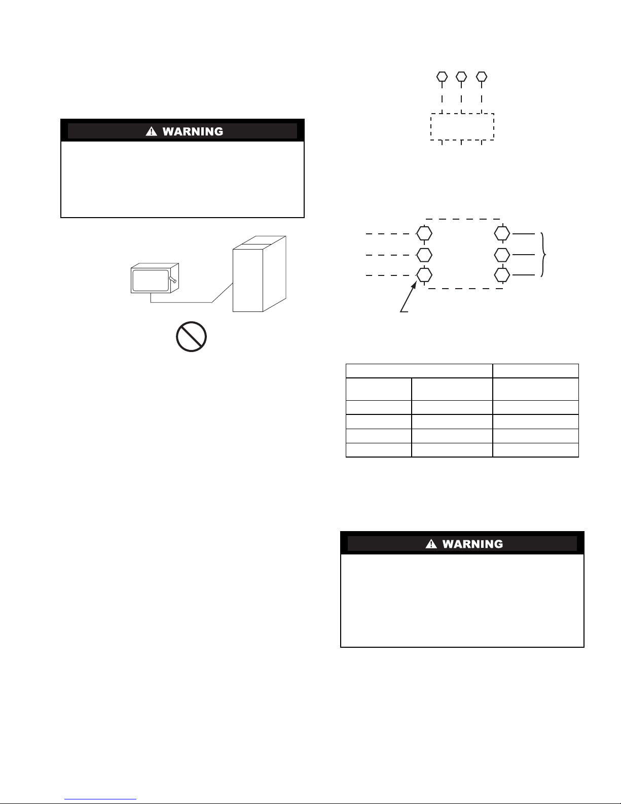
Do not connect aluminum wire between disconnect switch
and condensing unit. Use only copper wire.
(See Fig.10.)
Units Without Disconnect Option
CTB1
11 13
Disconnect
per
NEC
L1
L2 L3
208/230-3-60
460-3-60
575-3-60
Units With Disconnect Option
Fig. 10 — Disconnect Switch and Unit
Units Without Factory-Installed Disconnect —
When installing units, provide a disconnect switch of adequate
size per local or national wiring code. Disconnect sizing data is
provided on the unit informative plate. Locate on unit cabinet
or within sight of the unit per national or local codes. Do not
cover unit informative plate if mounting the disconnect on the
unit cabinet.
Units with Factory-Installed Disconnect —
The factory-installed option disconnect switch is located in a
weatherproof enclosure located under the main control box.
The manual switch handle is accessible through an opening in
the access panel.
All units -
All field wiring must comply with NEC and all local codes.
Size wire based on MCA (Minimum Circuit Amps) on the unit
informative plate. See Fig. 11 for power wiring connections to
the unit power terminal block and equipment ground.
Provide a ground-fault and short-circuit over-current protection
device (fuse or breaker) per NEC Article 440 (or local codes).
Refer to unit informative data plate for MOCP (Maximum
Over-current Protection) device size.
L1
L2
L3
2
4
6
Optional
Disconnect
Switch
1
3
5
Factory
Wiring
Disconnect factory test leads; discard.
Fig.11 — Power Wiring Connections
Table 10 — American/European Wire Conversions
AMERICAN EUROPEAN
Industry
Standard Size
20 AWG 0.52 0.5
18 AWG 0.82 1.0
16 AWG 1.30 1.5
14 AWG 2.08 2.5
American
Conversion (mm
2
)
European
Standard Size (mm2)
All field wiring must comply with the NEC and local
requirements.
Affix the crankcase heater warning sticker to the unit
disconnect switch.
Convenience Outlets —
ELECTRICAL OPERATION HAZARD
Failure to follow this warning could result in personal
injury or death.
Units with convenience outlet circuits may use multiple
disconnects. Check convenience outlet for power status
before opening unit for service. Locate its disconnect
switch, if appropriate, and open it. Tag-out this switch, if
necessary.
Two types of convenience outlets are offered on 38AU models:
Non-powered and unit-powered. Both types provide a 125-volt
GFCI (ground-fault circuit-interrupter) duplex receptacle rated
at 15-A behind a hinged waterproof access cover, located on
the end panel of the unit. See Fig. 12.
15
Page 16
Convenience
UNIT
VOLTAGE
CONNECTASPRIMARY
CONNECTIONS
TRANSFORMER
TERMINALS
208,
230
240
L1: RED + YEL
L2: BLU + GRA
H1 + H3
H2 + H4
460 480
L1: RED
Splice BLU +
YEL
L2: GRA
H1
H2 + H3
H4
575 600
L1: RED
L2: GRA
H1
H2
Outlet
GFCI
Pwd-CO
Fuse
Switch
Control Box
Access Panel
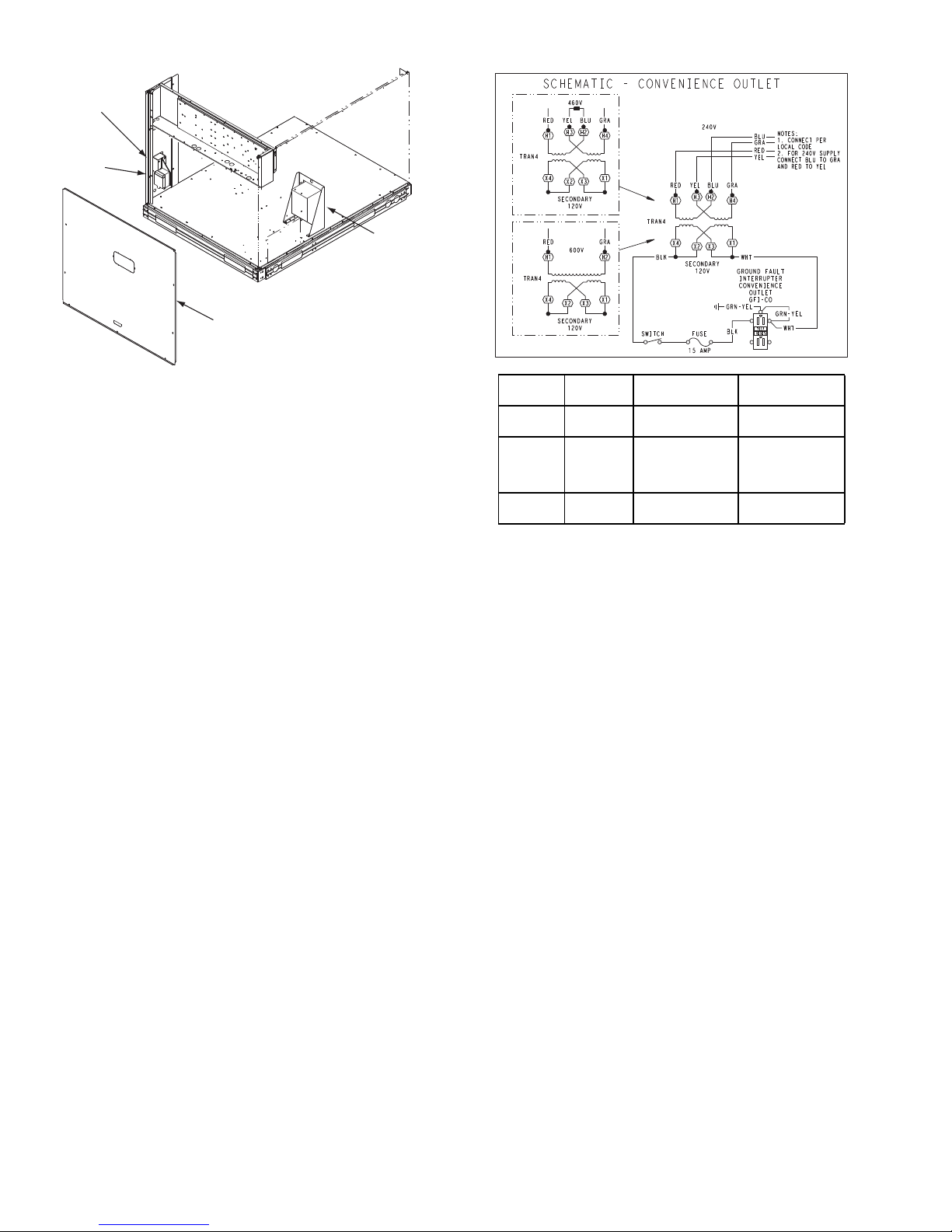
Fig. 12 — Convenience Outlet Location
Non-powered type: This type requires the field installation of
a general-purpose 125-volt 15-A circuit powered from a source
elsewhere in the building. Observe national and local codes
when selecting wire size, fuse or breaker requirements and
disconnect switch size and location. Route 125-v power supply
conductors into the bottom of the utility box containing the
duplex receptacle.
Unit-powered type: A unit-mounted transformer is factoryinstalled to stepdown the main power supply voltage to the unit
to 115-v at the duplex receptacle. This option also includes a
manual switch with fuse, located in a utility box and mounted
on a bracket behind the convenience outlet; access is through
the unit's control box access panel. See Fig. 12.
The primary leads to the convenience outlet transformer are not
factory-connected. Selection of primary power source is a
customer-option. If local codes permit, the transformer primary
leads can be connected at the line-side terminals on the unitmounted non-fused disconnect or HACR breaker switch; this
will provide service power to the unit when the unit disconnect
switch or HACR switch is open. Other connection methods
will result in the convenience outlet circuit being de-energized
when the unit disconnect or HACR switch is open. See Fig. 13.
Duty Cycle: The unit-powered convenience outlet has a duty
cycle limitation. The transformer is intended to provide power
on an intermittent basis for service tools, lamps, etc; it is not
intended to provide 15-amps loading for continuous duty loads
(such as electric heaters for overnight use). Observe a 50%
limit on circuit loading above 8-amps (i.e., limit loads
exceeding 8-amps to 30 minutes of operation every hour).
Test the GFCI receptacle by pressing the TEST button on the
face of the receptacle to trip and open the receptacle. Check for
proper grounding wires and power line phasing if the GFCI
receptacle does not trip as required. Press the RESET button to
clear the tripped condition.
Pwd-CO
Transformer
Fig. 13 - Powered Convenience Outlet Wiring
Fuse on power type: The factory fuse is a Bussman “Fusetron”
T-15, non-renewable screw-in (Edison base) type plug fuse.
Using unit-mounted convenience outlets: Units with unitmounded convenience outlet circuits will often require that two
disconnects be opened to de-energize all power to the unit.
Treat all units as electrically energized until the convenience
outlet power is also checked and de-energization is confirmed.
Observe and local codes, for use of convenience outlets.
Installing Weatherproof Cover –
A weatherproof while-in-use cover for the factory-installed
convenience outlets is required. This cover cannot be
factory-mounted due to its depth; it must be installed at unit
installation. For shipment, the convenience outlet is covered
with a blank cover plate.
The weatherproof cover kit is shipped in the unit's control box.
The kit includes the hinged cover, a backing plate and gasket.
DISCONNECT ALL POWER TO UNIT AND
CONVENIENCE OUTLET.
Remove the blank cover plate at the convenience outlet;
discard the blank cover.
Loosen the two screws at the GFCI duplex outlet, until
approximately
Press the gasket over the screw heads. Slip the backing plate
over the screw heads at the keyhole slots and align with the
gasket; tighten the two screws until snug (do not over-tighten).
Mount the weatherproof cover to the backing plate as shown in
Fig. 14. Remove two slot fillers in the bottom of the cover to
permit service tool cords to exit the cover. Check for full
closing and latching.
16
1
/2-in (13 mm) under screw heads are exposed.
Page 17
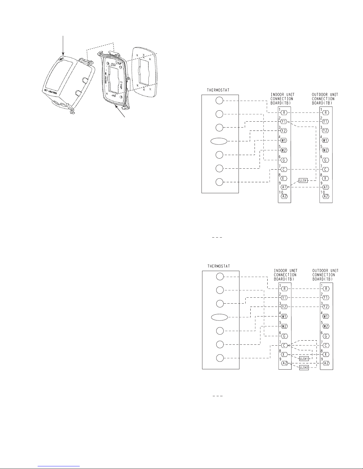
Fig. 14 — Weatherproof Cover Installation
RECEPTACLE
NOT INCLUDED
COVER – WHILE-IN-USE
WEATHERPROOF
BASE PLATE FOR
GFCI RECEPTACLE
Note 1: Typical multi-function marking. Follow manufacturer’s configuration
instructions to select Y2.
Note 2: Y2 to economizer required on single-stage cooling units when
integrated economizer function is desired
Note 3: Connect only if thermostat requires 24-vac power source.
Note 4: Connect W1 and W2 if supplemental heaters are installed
Field Wiring
R
Y1
G
O/B/Y2
C
W2
W1
(Notes 1, 2)
(Note 3)
(Note 4)
(Note 4)
Note 1: Typical multi-function marking. Follow manufacturer’s configuration
instructions to select Y2.
Note 2: Connect only if thermostat requires 24-vac power source.
Note 3: Connect W1 and W2 if supplemental heaters are installed
Field Wiring
R
Y1
G
O/B/Y2
C
W2
W1
(Notes 1)
(Note 3)
(Note 3)
(Note 3)
All Units —
Voltage to compressor terminals during operation must be
within voltage range indicated on unit nameplate. See Tables
10 and 11. On 3-phase units, voltages between phases must be
balanced within 2% and the current within 10%. Use the
formula shown in the legend for Tables 10 and 11, Note 5 (see
page 19) to determine the percent of voltage imbalance.
Operation on improper line voltage or excessive phase
imbalance constitutes abuse and may cause damage to
electrical components. Such operation would invalidate any
applicable Carrier warranty.
Field Control Wiring — 38AU unit control voltage is 24 v.
See Figs 23 and 24 for typical field control connections and the
unit’s label diagram for field-supplied wiring details. Route
control wires to the 38AU unit through the opening in unit’s
end panel to the connections terminal board in the unit’s
control box.
Remainder of the system controls connection will vary
according to the specific construction details of the indoor
section (air handler or packaged fan coil). Figs 15 (38AUZ)
and 16 (38AUD) depict typical connections to a Carrier 40RU
fan coil unit. Plan for field connections carefully and install
control wiring correctly per the project plan. Additional
components and supplemental transformer accessory may be
required.
The 38AU unit requires an external temperature control device.
This device can be a thermostat (field-supplied) or a
PremierLink controller (available as a field-installed accessory,
for use on a Carrier Comfort Network or as a stand alone
control).
Thermostat —
Install a Carrier-approved accessory thermostat according to
installation instructions included with the accessory. Locate the
thermostat accessory on a solid wall in the conditioned space to
sense average temperature in accordance with the thermostat
installation instructions.
38AUZ Unit – 38AUZ unit is a single-stage cooling unit. If no
economizer function is required, select a single-stage cooling
thermostat. If an integrated economizer function is required,
select a two—stage cooling thermostat.
38AUD Unit – 38AUD unit is a two-stage cooling unit. Select
a two-stage cooling thermostat.
Select a thermostat cable or equivalent single leads of different
colors with minimum of four leads for 38AUZ unit or five
leads for 38AUD units. Check the thermostat installation
instructions for additional features which might require
additional conductors in the cable.
For wire runs up to 15 m (50 ft.), use no. 18 AWG (American
Wire Gage) insulated wire (35°C minimum). For 15 to 23 m
(50 to 75 ft.), use no. 16 AWG insulated wire (35°C minimum).
For over 23 m (75 ft.), use no. 14 AWG insulated wire (35°C
minimum). All wire sizes larger than no. 18 AWG cannot be
directly connected to the thermostat and will require a junction
box and splice at the thermostat.
PremierLink (accessory installation) – Refer to Form 33CS58SI for details on connecting the PremierLink controller and
its various sensors.
Fig. 15 — Typical Remote Thermostat Connections
— 38AUZ
Fig. 16 — Typical Remote Thermostat Connections
— 38AUD
17
Page 18
External Devices – The 38AU control transformers provide 24-
Example: Supply voltage is 230-3-60
AB = 224 v
BC = 231 v
AC = 226 v
Average Voltage =
(224 + 231 + 226)
=
681
3
3
=227
Determine maximum deviation from average voltage.
(AB) 227 – 224 = 3 v
(BC) 231 – 227 = 4 v
(AC) 227 – 226 = 1 v
Maximum deviation is 4 v.
Determine percent of voltage imbalance.
%VoltageImbalance =100 x
4
227
=1.76%
This amount of phase imbalance is satisfactory as it is below the
maximum allowable 2%.
IMPORTANT: If the supply voltage phase imbalance is more than
2%, contact your local electric utility company immediately.
% Voltage Imbalance = 100 x
max voltage deviation from average voltage
average voltage
v NEC Class 2 power sources to energize external control devices. These devices will include the indoor fan motor contactor (or control relay). These devices may also include liquid
line solenoid valve (two on 38AUD model), economizer control relay, supplemental electric heater contactors or control relays and other devices selected by system designer.
Control transformer TRAN1 provides control power through
terminal R to C on the CTB’s field connection terminal strip for
supply fan motor interlock. This source may also be used to en-
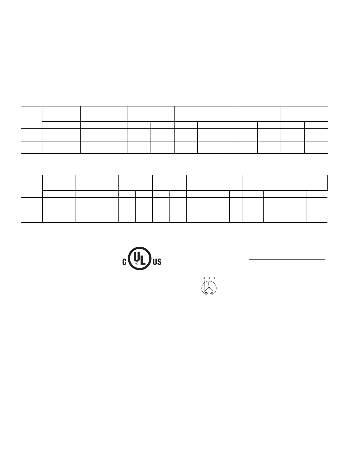
Table 11 — Electrical Data — 38AUZ*07-08 60 Hz Units
ergize economizer control relay and electric heater contactors
or relays. Maximum available power is 20 va. Check concurrent loadings by external control devices. If the maximum concurrent loading exceeds 20 va, purchase and install the accessory Transformer-Relay package (available for 208/230 and
460-v units).
Control transformer TRAN3 provides control power through
terminals A1 (9) and A2 (10) to C for liquid line solenoids.
Maximum available power is 40 va. These outputs are
switched ON/OFF by the Solenoid Valve Relays.
UNIT
SIZE
38AU
Z*07
Z*08
UNIT
SIZE
38AU
D*12
D*14
LEGEND AND NOTES FOR TABLES 11 & 12
FLA —
LRA —
MCA —
MOCP —
NEC —
RLA —
‡
Units are suitable for use on electrical systems where voltage supplied to
the unit terminals is not below or above the listed limits.
NOTES:
1. The MCA and MOCP values are calculated in accordance with the NEC,
Article 440.
2. Motor RLA and LRA values are established in accordance with
Underwriters’ Laboratories (UL), Standard 1995.
3. The 575-v units are UL, Canada-listed only.
4. Convenience outlet is available as a factory-installed option and is 115-v,
1 ph, 60 Hz.
NOMINAL
VOLTAGE
V-Ph-Hz MIN MAX RLA LRA WATTS FLA QTY MCA MOCP MCA MOCP
400-3-50 380 420 9.7 64 270 0.7 2 13.5 20 15.9 25
400-3-50 380 420 12.2 101 270 0.7 2 16.7 25 19.0 30
NOMINAL
VOLTAGE
V-Ph-Hz MIN MAX RLA LRA RLA LRA WATTS FLA QTY MCA MOCP MCA MOCP
208/230-3-60 380 420 7.8 51.5 7.8 51.5 270 0.7 2 19.0 25 21.3 30
208/230-3-60 380 420 10.6 74 10.6 74 270 0.7 2 25.3 30 27.6 30
Full Load Amps
Locked Rotor Amps
Minimum Circuit Amps
Maximum Overcurrent
Protection
National Electrical Code
Rated Load Amps
VOLTAGE
RANGE
VOLTAGE
RANGE
‡
COMPRESSOR
OUTDOOR
FAN MOTORS (ea)
WITHOUT POWERD
Table 12 — Electrical Data — 38AUD*12-14 60 Hz Units
COMPRESSOR 1COMPRESSOR
‡
2
OUTDOOR
FAN MOTORS (ea)
5. Unbalanced 3-Phase Supply Voltage
Never operate a motor where a phase imbalance in supply voltage is
greater than 2%. Use the following formula to determine the percentage
of voltage imbalance.
CONVENIENCE
OUTLET
WITHOUT POWERD
CONVENIENCE
OUTLET
WITH POWERD
CONVENIENCE
OUTLET
WITH POWERD
CONVENIENCE
OUTLET
18
Page 19

PRE-START-UP
START-UP
IMPORTANT: Before beginning Pre-Start-Up or Start-Up,
review Start-Up Checklist at the back of this book. The
Checklist assures proper start-up of a unit and provides a
record of unit condition, application requirements, system
information, and operation at initial start-up.
UNIT DAMAGE HAZARD
Do not attempt to start the condensing unit, even
momentarily, until the following steps have been
completed. Compressor damage may result.
System Check
1. Check all air handler(s) and other equipment auxiliary
components. Consult the manufacturer’s instructions
regarding any other equipment connected to the condensing unit. If the unit has field-installed accessories,
be sure all are properly installed and correctly wired. If
used, the airflow switch must be properly installed.
2. Be sure the unit is properly leak checked and dehydrated.
3. Check tightness of all electrical connections.
4. Open the liquid line and suction line service valves.
5. Be sure the unit is properly charged. See “Preliminary
Charge”, below.
6. The electrical power source must agree with the unit’s
nameplate rating.
7. The crankcase heater must be firmly attached to the compressor crankcase. Be sure the crankcase is warm (heater
must be on for 24 hours before starting compressor).
Turn On Crankcase Heater
Turn on the crankcase heater for 24 hours before starting the
unit to be sure all the refrigerant is out of the oil. To energize
the crankcase heater, proceed as follows:
1. Set the space thermostat set point above the space temperature so there is no demand for cooling.
2. Close the field disconnect.
Preliminary Charge
Before starting the unit, charge liquid refrigerant into the high
side of the system(s) through the liquid service valve(s). The
amount of refrigerant added must be at least 80% of the
operating charge listed in the Physical Data table (Tables 1A
through 2B, pages 4 through 7). Open the liquid line and
suction line service valves. Allow high and low side pressures
to equalize before starting compressor. If pressures do not
equalize readily, charge vapor on low side of system to assure
charge in the evaporator. Refer to GTAC II, Module 5,
Charging, Recover, Recycling, and Reclamation for liquid
charging procedures.
UNIT DAMAGE HAZARD
Prior to starting compressor, a preliminary charge of
refrigerant must be added to avoid possible compressor
damage.
38AU Units
The compressor crankcase heater(s) must be on for 24 hours
before start-up. After the heater has been on for 24 hours, the
unit can be started. If no time elapsed since the preliminary
charge step was completed, it is unnecessary to wait the 24hour period.
Preliminary Checks
1. Check that electric power supply agrees with unit
nameplate data.
2. Verify that the compressor crankcase heater is securely in
place.
3. Check that the compressor crankcase heater has been on
at least 24 hours.
4. Recheck for leaks using the procedure outlined in the
Pre-Start-Up section, Leak Test and Dehydration. If any
leaks are detected, repair as required. Evacuate and
dehydrate as described in the Leak Test and Dehydration
section.
5. Ensure that the preliminary charge has been added as
described in the Pre-Start-Up section, Preliminary
Charge.
6. All internal wiring connections must be tight, and all
barriers and covers must be in place.
NOTE: The 38AU units are factory charged with the
required amount of oil. If recharging in required, use
Emkarate RL 32-3MAF for the 38AU units.
Compressor Rotation
On 3-phase units with scroll compressors, it is important to be
certain that the compressor is rotating in the proper direction.
38AU units are equipped with a Comfort Alert Diagnostic
Module (CADM). Alert Code 7 indicates reverse power
phasing.
To correct phase order:
1. Turn off power to the unit, tag disconnect.
2. Reverse any two of the unit power leads.
3. Reapply power to the compressor, verify correct pressures.
To verify the compressor is rotating in the proper direction:
1. Connect service gages to the suction and liquid pressure
fittings.
2. Energize the compressor.
The suction pressure should drop and the liquid pressure
should rise, as is normal on any start-up.
Compressor Overload
This overload interrupts power to the compressor when either
the current or internal motor winding temperature becomes excessive, and automatically resets when the internal temperature
drops to a safe level. This overload may require up to 60 minutes (or longer) to reset. If the internal overload is suspected of
being open, disconnect the electrical power to the unit and
check the circuit through the overload with an ohmmeter or
continuity tester.
19
Page 20

Advanced Scroll Temperature Protection (ASTP)
0
10
20
30
40
50
60
70
80
90
100
110
120
0 102030405060708090
Compressor Unloaded Run Time (Minutes)
Recommended Cooling Time
(Mi
nut
es)
*Times are approximate.
NOTE: Various factors, including high humidity, high ambient tem-
perature, and the presence of a sound blanket will increase cooldown times.
A label located above the terminal box identifies Copeland
Scroll compressor models that contain this technology. See Fig.
17. Advanced Scroll Temperature Protection (ASTP) is a form
of internal discharge temperature protection, that unloads the
scroll compressor when the internal temperature reaches approximately 300°F. At this temperature, an internal bi-metal
disk valve opens and causes the scroll elements to separate,
which stops compression. Suction and discharge pressures balance while the motor continues to run. The longer the compressor runs unloaded, the longer it must cool before the bi-metal
disk resets. See Fig. 18.
Fig. 17 — Advanced Scroll Temperature
Protection Label
Start Unit
Set the space thermostat to a set point above space temperature
so that there is no demand for cooling. Close the 38 AU disconnect switch. Only the crankcase heater will be energized.
Reset the space thermostat below space temperature so that a
call for cooling is ensured.
Never charge liquid into the low-pressure side of system.
Do not overcharge. During charging or removal of refrigerant, be sure indoor-fan system is operating. Ensure both
outdoor fan motors are running; bypass any Motormaster
or mild-ambient control function.
Adjust Refrigerant Charge
The unit must be charged in Cooling mode only. Refer to Cooling Charging Charts, Fig. 19 through Fig. 22. Vary refrigerant
until the conditions of the chart are met. Note that the charging
charts are different from the type normally used. The charts are
based on charging the units to the correct subcooling for the
various operating conditions. Accurate pressure gage and temperature sensing device are required. Connect the pressure
gage to the service port on the liquid line service valve. Mount
the temperature sensing device on the liquid line close to the
liquid line service valve, and insulate it so that outdoor ambient
temperature does not affect the reading. Indoor airflow must be
within the unit’s normal operating range. Operate the unit for a
minimum of 15 minutes. Ensure that pressure and temperature
readings have stabilized. Plot the liquid pressure and temperature on chart and add or reduce the charge to meet the curve.
Adjust the charge to conform with the charging chart, using the
liquid pressure and temperature to read the chart.
Fig. 18 — Recommended Minimum Cool-Down Time
After Compressor is Stopped
To manually reset ASTP, the compressor should be stopped
and allowed to cool. If the compressor is not stopped, the motor
will run until the motor protector trips, which occurs up to
90 minutes later. Advanced Scroll Temperature Protection will
reset automatically before the motor protector resets, which
may take up to 2 hours.
FINAL CHECKS
Ensure that all safety controls are operating, control panel
covers are on, and the service panels are in place.
20
Page 21
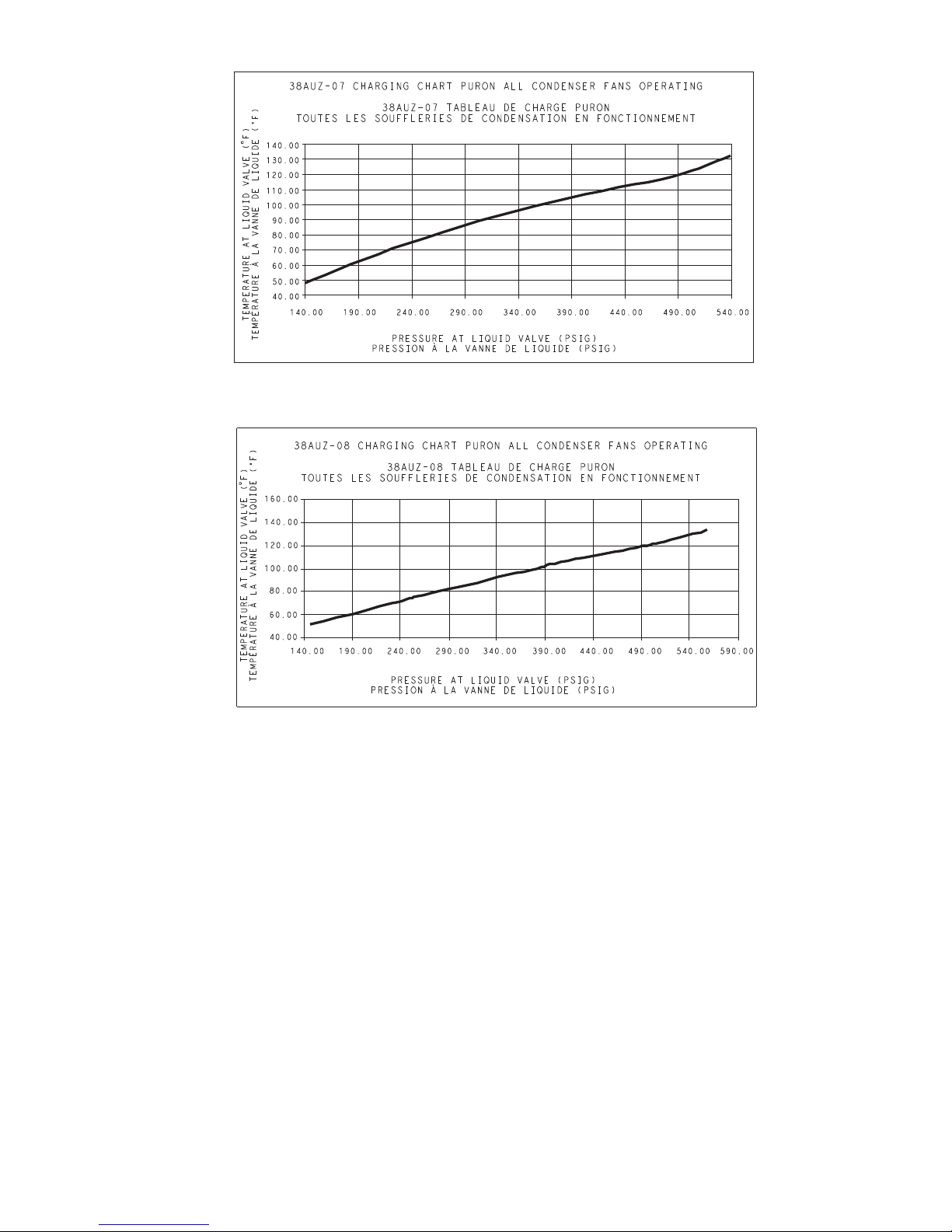
Fig. 19 — 38AUZ*07 Charging Chart
Fig. 20 — 38AUZ*08 Charging Chart
21
Page 22
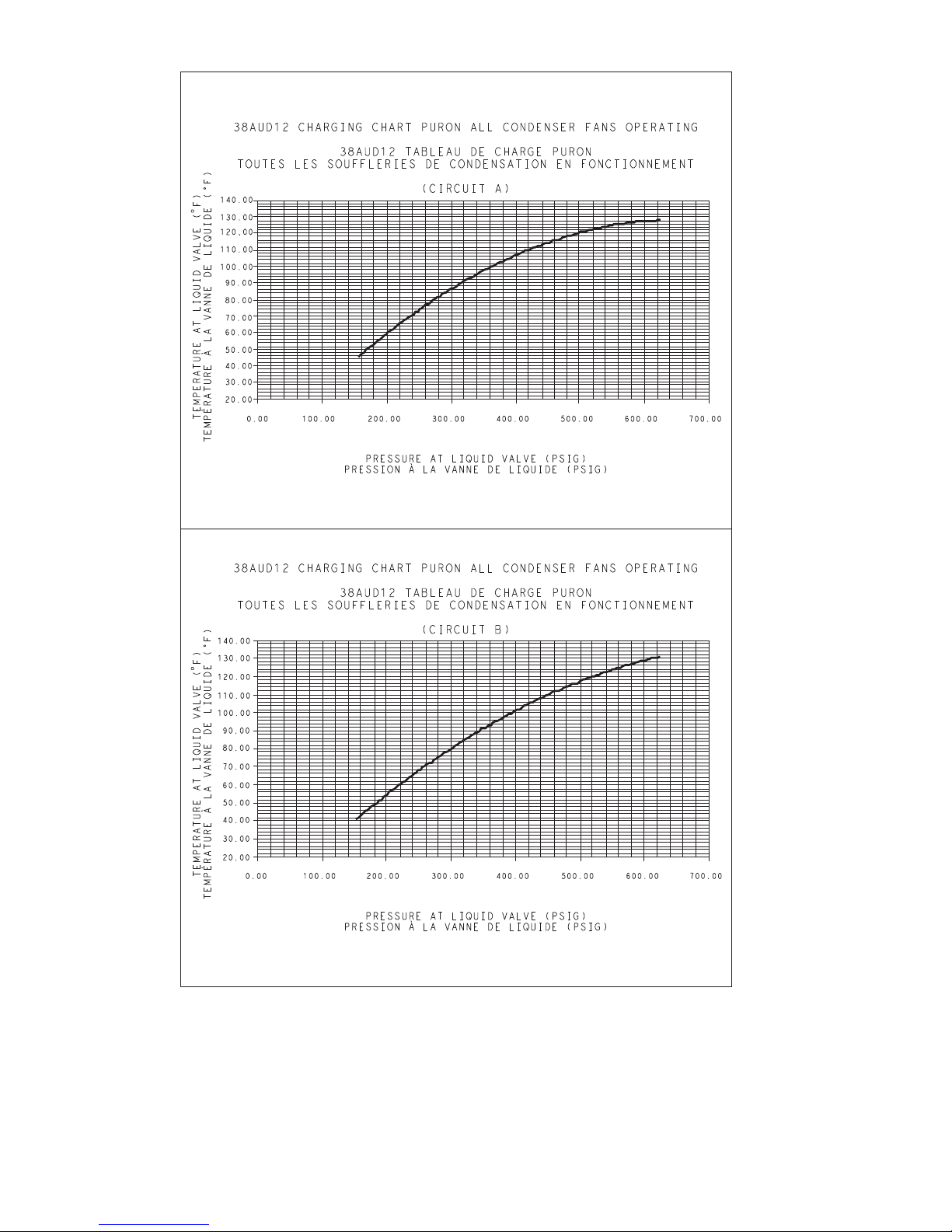
Fig. 21 — 38AUD*12 Charging Chart
22
Page 23

Fig. 22 — 38AUD*14 Charging Chart
23
Page 24
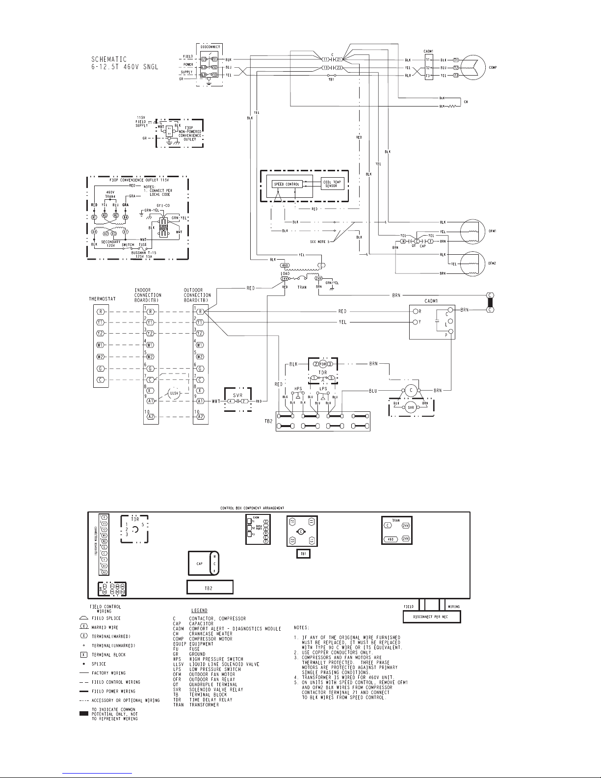
Fig. 23 — Typical 38AUZ Wiring Diagram (50Hz Single Circuit Unit Shown)
24
Page 25
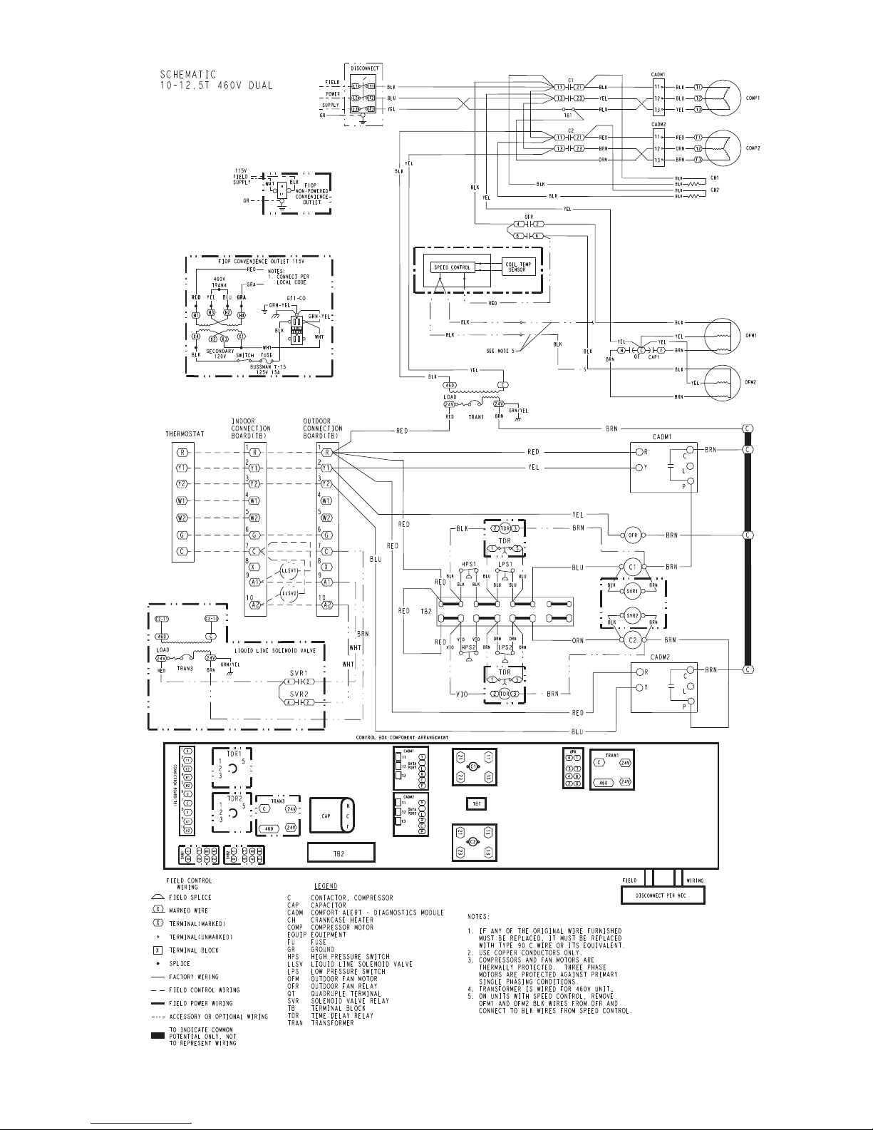
Fig. 24 — Typical 38AUD Wiring Diagram (50Hz Dual Circuit Unit Shown)
25
Page 26

OPERATING SEQUENCE
ROUTINE SYSTEM MAINTENANCE
Base Unit Controls
Indoor (Supply) Fan
The indoor fan contactor (IFC) is remotely located at the fan
coil or fan section. If the thermostat fan operation is selected as
Continuous, the IFC is energized and the indoor (supply) fan
motor runs continuously. If the thermostat fan operation is
selected as Automatic, the IFC will be energized on a call for
Cooling; indoor (supply) fan motor runs. When thermostat call
for Cooling is satisfied, the IFC is de-energized and indoor
(supply) fan motor stops.
Cooling, Unit Without Economizer
On a thermostat call for Cooling, IFC will be energized and
indoor (supply) fan motor runs. Thermostat contact TC1
closes; terminal Y1 at 38AU unit receives 24-v. 24-v received
at CADM terminal Y. If anti-recycle time delay period has not
expired, CADM relay will remain open, preventing
compressor start. When safety pressure switches are closed, the
liquid line solenoid valve opens. When CADM time delay
expires, the compressor contactor is energized; both outdoor
fan motors start and compressor starts.
38AUD Second-Stage Cooling —
On a thermostat calling for Stage 2 Cooling, thermostat contact
TC2 closes; terminal Y2 at 38AUD unit receives 24-v. 24-v
received at CADM2 terminal Y. If anti-recycle time delay
period has not expired, CADM relay will remain open,
preventing compressor start. When safety pressure switches are
closed, the liquid line solenoid valve opens. When CAMD time
delay expires, the compressor contactor C2 is energized;
Compressor B starts.
When space cooling load is satisfied, thermostat contacts TC1
open, removing 24-v at 38AU terminal Y1. Compressor and
outdoor fan motors stop. Liquid line solenoid valve is
de-energized and valve closes. CADM begins its three-minute
anti-recycle time delay.
If either the Low Pressure Switch or High Pressure Switch
opens while thermostat contact TC1 (or TC2 on 38ARD)
remains closed, the compressor contactor is de-energized (both
fan motors and compressor stop) and liquid line solenoid is deenergized (valve closes). CADM initiates a TRIP event
(cooling demand sensed at CADM terminal Y but no current is
measured at T1, T2, T3 motor sensors); CADM relay opens
and RED LED is illuminated. TRIP condition maintains
lockout of compressor operation until CADM is manually
reset. Reset CADM by cycling unit main power.
Complete system shutdown may be caused by loss of main
power, open compressor internal overload, open low-pressure
or high-pressure switch, or a fault detected by the CADM
logic. Compressor operation without cooling may indicate the
compressor’s ASTP feature is active (unit sizes 12 and 14
only); disconnect unit power and allow compressor to cool. See
Service section for further details.
Cooling, Unit With Economizer
Refer to fan coil unit installation instructions and economizer
accessory installation instructions for operating sequences
when system is equipped with accessory economizer.
Heating
Refer to fan coil unit installation instructions and accessory
heating device installation instructions for operating sequences
in heating mode.
These items should be part of a routine maintenance program,
to be checked every month or two, until a specific schedule for
each can be identified for this installation:
Quarterly Inspection
(and 30 days after initial start)
Indoor section
• Condenser coil cleanliness checked.
• Return air filter replacement
• Outdoor hood inlet filters cleaned
• Belt tension checked
• Belt condition checked
• Pulley alignment checked
• Fan shaft bearing locking collar tightness checked
• Condensate drain checked
Seasonal Maintenance
These items should be checked at the beginning of each season
(or more often if local conditions and usage patterns dictate):
Air Conditioning
• Condenser fan motor mounting bolts tightness
• Compressor mounting bolts
• Condenser fan blade positioning
• Control box cleanliness and wiring condition
• Wire terminal tightness
• Refrigerant charge level
• Evaporator coil cleaning
• Evaporator blower motor amperage
Heating
• Power wire connections
• Fuses ready
• Manual-reset limit switch is closed
Economizer or Outside Air Damper
• Inlet filters condition
• Check damper travel (economizer)
• Check gear and dampers for debris and dirt
26
Page 27
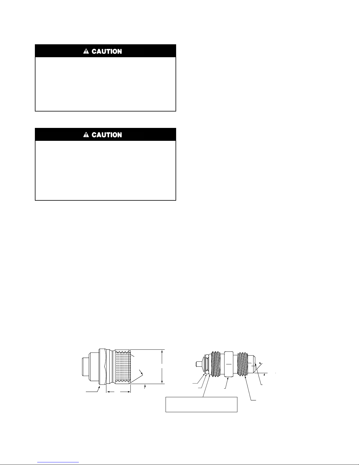
SERVICE
1/2-20 UNF RH
30°
0.596
.47
5/8” HEX
SEAT
CORE
WASHER
DEPRESSOR PER ARI 720
+.01/-.035
FROM FACE OF BODY
7/16-20 UNF RH
O-RING
45°
1/2" HEX
This surface provides a metal to metal seal when
torqued into the seat. Appropriate handling is
required to not scratch or dent the surface.
(Part No. EC39EZ067)
Refrigeration System
EQUIPMENT DAMAGE HAZARD
Failure to follow this caution may result in damage to
equipment.
This system uses Puron® refrigerant which has higher
pressures than R-22 and other refrigerants. No other refrigerant may be used in this system. Gage set, hoses, and recovery system must be designed to handle Puron®. If you
are unsure consult the equipment manufacturer.
Compressor Oil —
EQUIPMENT DAMAGE HAZARD
Failure to follow this caution may result in damage to
equipment.
The compressor in a Puron system uses a polyolester
(POE) oil. This oil is extremely hygroscopic, meaning it
absorbs water readily. POE oils can absorb 15 times as
much water as other oils designed for HCFC and CFC refrigerants. Take all necessary precautions to avoid exposure
of the oil to the atmosphere.
Servicing Systems on Roofs With Synthetic
Materials —
known to cause long term damage to some synthetic roofing
materials. Exposure, even if immediately cleaned up, may
cause embrittlement (leading to cracking) to occur in one year
or more. When performing any service which may risk exposure of compressor oil to the roof, take appropriate precautions
to protect roofing. Procedures which risk oil leakage include
but are not limited to compressor replacement, repairing refrigerants leaks, replacing refrigerant components such as filter
drier, pressure switch, metering device, coil, accumulator, or
reversing valve.
SYNTHETIC ROOF PRECAUTIONARY PROCEDURE
1. Cover extended roof working area with an impermeable
polyethylene (plastic) drop cloth or tarp. Cover an approximate 3.3 x 3.3 m (10 x 10 ft) area.
2. Cover area in front of the unit service panel with a terry
cloth shop towel to absorb lubricant spills and prevent
POE (polyolester) compressor lubricants are
run-offs, and protect drop cloth from tears caused by tools
or components.
3. Place terry cloth shop towel inside unit immediately under component(s) to be serviced and prevent lubricant
run-offs through the louvered openings in the base pan.
4. Perform required service.
5. Remove and dispose of any oil contaminated material per
local codes.
Liquid Line Filter Drier — The factory-provided filter
drier is specifically designed to operate with Puron®. Replace
the filter drier with factory-authorized components only with a
filter drier with desiccant made from 100% molecular sieve
grade XH-11. Filter drier must be replaced whenever the refrigerant system is opened.
When removing a filter drier, use a tubing cutter to cut the drier
from the system. Do not unsweat a filter drier from the system. Heat from unsweating will release moisture and contaminants from drier into system.
Field Refrigerant Access Ports — Field service
access to refrigerant pressures is through the access ports
located at the service valves (see Figs 27 and 29). These ports
are ¼-in SAE Flare couplings with Schrader check valves and
service caps. Use these ports to admit nitrogen to the field
tubing during brazing, to evacuate the tubing and evaporator
coil, to admit initial refrigerant charge into the low-side of the
system and when checking and adjusting the system refrigerant
charge. When service activities are completed, ensure the
service caps are in place and secure; check for leaks. If the
Schrader check valve must be removed and re-installed, tighten
to 23-34 N-cm (2-3 in-lbs).
Factory High-Flow Access Ports — There are two
additional access ports in the system - on the suction tube
between the compressor and the suction service valve and on
the liquid tube near the liquid service valve (see Figs 28 and
30). These are brass fittings with black plastic caps. The hose
connection fittings are standard ¼-in SAE Male Flare
couplings.
The brass fittings are two-piece High Flow valves, with a receptacle base brazed to the tubing and an integral spring-closed
check valve core screwed into the base. (See Fig. 25) This
check valve is permanently assembled into this core body and
cannot be serviced separately; replace the entire core body if
necessary. Service tools are available from RCD that allow the
replacement of the check valve core without having to recover
the entire system refrigerant charge. Apply compressor refrigerant oil to the check valve core's bottom o-ring. Install the fitting body with 1085 ±23 N-cm (96 ±-10 in-lbs) of torque; do
not overtighten.
Fig. 25 — CoreMax Access Port Assembly
27
Page 28

Comfort Alert Diagnostic Module
The Comfort Alert Diagnostic Module (CADM) monitors and
analyzes data from the Copeland Scroll
sor and the thermostat demand. The CADM also provides a
3-minute anti-recycle time delay to compressor cycling.
The CADM detects causes for electrical and system related
failures without any sensors. Flashing LEDs communicate the
Alert codes to guide service technicians in accurately and
quickly troubleshooting the system and determining root cause
for the failure.
Inputs to the CADM include 24-vac power, thermostat Y1,
compressor contactor coil (common side) and compressor
power leads (from the compressor contactor).
Input Terminal Voltage
Control
Power
Control
Common
Cooling Y 24-V
Contactor
Coil
Line A T1 Line
Line B T2 Line
Line C T3 Line
Control of the compressor contactor coil is through a
normally-closed (power on the module) contact between
terminals P and C.
Communications of status and alert conditions is through three
LEDs located on the top edge of the module housing (see
Fig. 26): POWER (green), ALERT (yellow), and TRIP (red).
The POWER LED indicates the presence of control power to
the CADM.
®
three-phase compres-
R 24-V
C 24-V
P 24-V
POWER
(GRN)
ALERT
(YEL)
TRIP
(RED)
Fig. 26 — CADM Housing/LED Locations
The ALERT LED indicates an abnormal condition exists in the
system through a flash code. The ALERT LED will blink a
number of times consecutively, pause and the repeat the
process. The number of blinks, defined in Table 13, correlates
to a particular abnormal condition; troubleshooting tips are
provided for each Alert code. Reset of the ALERT may be
automatic or manual. If the fault condition causing the Alert is
self-corrected, the Alert code will be removed and the CADM
will automatically reset and allow the system to restart
normally. Manual reset requires that main power to the 38AU
unit be recycled after the cause for the Alert condition has been
detected and corrected.
The TRIP LED indicates either a time-delay period is currently
active (RED LED is blinking) or the module has locked out the
compressor (RED LED is on steady). A lockout condition will
occur when the CADM detects a thermostat demand at input Y
but there is no power at the compressor line terminals T1 or T2
or T3. This lockout can occur due to a safety switch (LPS or
HPS) opening and de-energizing the compressor contactor, the
compressor-motor internal overload opens, or other internal
power interruption has occurred. Reset of the TRIP LED
requires that unit main power be recycled after the loss of
power to the compressor condition has been detected and
corrected.
Simultaneous Blinking of YELLOW and RED LEDs indicates
control power input to the CADM is low. Check control circuit
transformer and wiring.
Troubleshooting the CADM Wiring – Flashing LEDs also
indicate wiring problems to the CADM. See Table 14 for
discussion of additional LED flash codes and troubleshooting
instructions.
28
Page 29
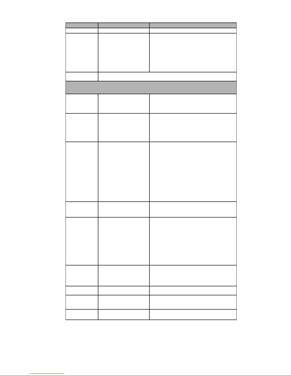
Table 13 — LED Status Codes
Status LED Status LED Description Status LED Troubleshooting Information
Green “POWER” Module has power Supply voltage is present at module terminals
Red “TRIP”
LED On Solid
Red “TRIP” LED
Flashing
Module locks out compressor when compressor damaging ALERT code appears.
Lockout ALERT codes are noted in the Status LED Description.
During a compressor lock out, 24VAC power must be removed from module to manually reset.
Yellow “ALERT”
LED On Solid
Yellow “ALERT”
Flash Code 2
Yellow “ALERT”
Flash Code 3
Yellow “ALERT”
Flash Code 4
Yellow “ALERT”
Flash Code 5
Yellow “ALERT”
Flash Code 6
Yellow “ALERT”
Flash Code 7
Yellow “ALERT”
Flash Code 8
Yellow “ALERT”
Flash Code 9
Thermostat demand signal Y
is present, but the
compressor is not running.
The anti-short cycle timer (3 minutes), in module is preventing compressor
restart.
A short circuit or over current
condition exists on PROT
terminal.
System Pressure Trip
Discharge pressure out of
limits or compressor
overload (if no high pressure
switch in system)
LOCKOUT
Short Cycling
Compressor is running only
briefly LOCKOUT
Locked Rotor
LOCKOUT
Open Circuit 1. Condensing unit power disconnect is open
Missing Phase
LOCKOUT
Reverse Phase
LOCKOUT
Welded Contactor
Compressor always runs
Low Voltage
Control circuit < 18VAC
1. Compressor protector is open
2. Condensing unit power disconnect is open
3. Compressor circuit breaker or fuse(s) is open
4. Broken supply wires or connector is not
making contact
5. Compressor power wires not routed through
Comfort Alert
6. Compressor contactor has failed open
1. Compressor contactor coil shorted
2. Electrical load too high for PROT circuit
(maximum 1 Amp)
3. 24 V AC wired directly to PROT terminal
1. High head pressure
2. Condenser coil poor air circulation (dirty,
blocked, damaged)
3. Condenser fan is not running
4. If low pressure switch is open:
Refer to Code 3 for troubleshooting
1. If low pressure switch is open:
a. Low refrigerant charge
b. Evaporator blower is not running
c. Evaporator coil is frozen
d. Faulty metering device
e. Condenser coil is dirty
f. Liquid line restriction (filter drier blocked if
present)
2. If high pressure switch is open, go to Flash
Code 2 information
3. Intermittent thermostat demand signal
4. System or control board defective
1. Low line voltage to compressor
2. Excessive liquid refrigerant in compressor
3. Compressor bearings are seized
2. Compressor circuit breaker or fuses are open
3. Compressor contactor has failed open
4. High pressure switch is open and requires
manual reset
5. Broken supply wires or connector is not
making contact
6. Unusually long compressor protector reset
time due to extreme ambient temperature
7. Compressor windings are damaged
1. Compressor fuse is open on one phase
2. Broken wire or connector on one phase
3. Compressor motor winding is damaged
4. Utility supply has dropped one phase
1. Compressor running backward due to supply
phase reversal
1. Compressor contactor has failed closed
2. Thermostat demand signal not connected to
module
1. Control circuit transformer is overloaded
2. Low line voltage to compressor
29
Page 30
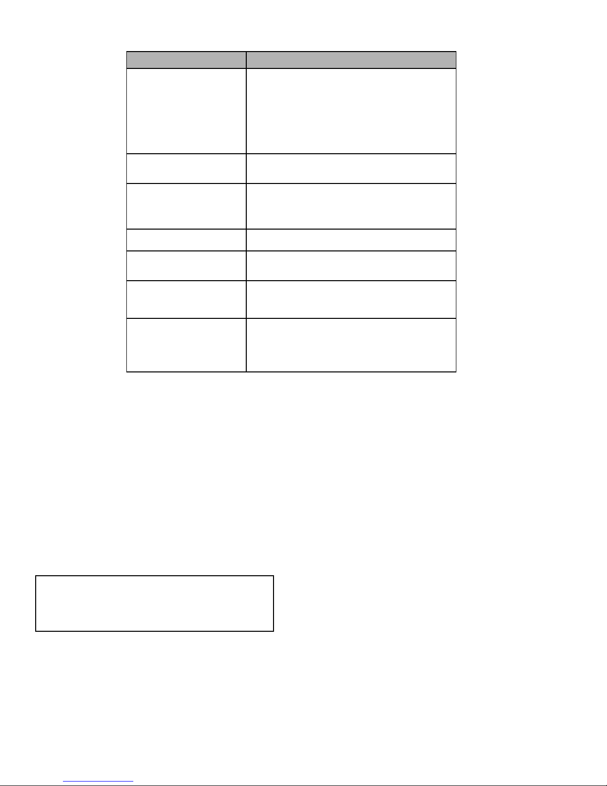
Table 14 — CADM Troubleshooting
Miswired Module Indication Recommended Troubleshooting Action
Green LED is not on,
module does not power up
Green LED Intermittent,
module powers up only
when compressor runs
TRIP LED is on but system
and compressor check OK
TRIP LED and ALERT LED
flashing together
ALERT Flash Code 3
(Compressor Short Cycling)
displayed incorrectly
ALERT Flash Code 5 or 6
(Open Circuit, Missing Phase)
displayed incorrectly
Alert Flash Code *
(Welded Contactor)
displayed incorrectly
Determine if both R and C module terminals are
connected. Verify voltage in present at module’s R and C
terminals.
NOTE: The CADM requires a constant nominal 24VAC
power supply. The wiring to the module’s R and C
terminals must be directly from the control transformer.
The module cannot receive its power from another device
that will interrupt the 24VAC power supply. See Fig. 23
and (38AUZ Wiring Diagram) and Fig. 24 (38AUD Wiring
Diagram).
Determine if R and Y terminals are wired in reverse. Verify
module’s R and C terminals have a constant source. See
“NOTE” above for details on R and C wiring.
Verify Y terminal is wired properly per the 38AU wiring
diagram (see Figs. 23 and 24). Verify voltage at contactor
coil falls below 0.5VAC when off. Verify 24VAQC is present
across Y and C when thermostat demand signal is
present. If not, R and C are reverse wired.
Verify R and C terminals are supplied with 19-28VAC.
Verify Y terminal is connected to 24VAC at contactor coil.
Verify voltage at contactor coil falls below 0.5VAC when
off.
Check that compressor T1 and T3 wires are through
module’s current sensing holes. Verify Y terminal is
connected to 24VAC at contactor coil. Verify voltage at
contactor coil falls below 0.5VAC when off.
Determine if module’s Y terminal is connected. Verify Y
terminal is connected to 24VAC at contactor coil. Verify
24VAC is present across Y and C when thermostat
demand signal is present. If not, R and C are reverse
wired. Verify voltage at contactor coil falls below 0.5VAC
when off.
Crankcase Heater — The heater prevents refrigerant
migration and compressor oil dilution during shutdown whenever compressor is not operating. The heater is wired to cycle
with the compressor; the heater is off when compressor is running, and on when compressor is off.
The crankcase heater will operate as long as the power circuit
is energized.
Compressor Protection
COMPRESSOR OVERTEMPERATURE PROTECTION
(IP) — A thermostat installed on the compressor motor winding reacts to excessively high winding temperatures and shuts
off the compressor.
CRANKCASE HEATER — The heater minimizes absorption of liquid refrigerant by oil in the crankcase during brief or
extended shutdown periods. The main disconnect must be on
to energize the crankcase heater.
IMPORTANT: Never open any switch or disconnect that
energizes the crankcase heater unless unit is being serviced
or is to be shut down for a prolonged period. After a prolonged shutdown on a service job, energize the crankcase
heater for 24 hours before starting the compressor.
ADVANCED SCROLL TEMPERATURE PROTECTION
(ASTP) — See “Advanced Scroll Temperature Protection
(ASTP)” on page 21.
Low-Pressure Switch — The 38AU low-pressure
switch is stem-mounted on the suction line. Switches are all
fixed, non-adjustable type.
High-Pressure Switch — The 38AU high-pressure
switch is stem-mounted on the discharge line. The switch is a
fixed, non-adjustable type.
Outdoor Fans — Each fan is supported by a formed-wire
mount bolted to the fan deck and covered with a wire guard.
Fan motors have permanently lubricated bearings.
Lubrication
FAN MOTORS have sealed bearings. No provisions are made
for lubrication.
COMPRESSOR has its own oil supply. Loss of oil due to a
leak in the system should be the only reason for adding oil after
the system has been in operation.
30
Page 31

Condenser Fans
Service
Valves
HPS
LPS
High Flow
Access Port
32LT Sensor
Typical Location
Outdoor Coil
Fig. 27 — Typical Exterior, Single-Circuit Unit (38AUZ*08 shown)
Fig. 28 — Typical Interior, Single-Circuit Unit (38AUZ*08 shown)
31
Page 32
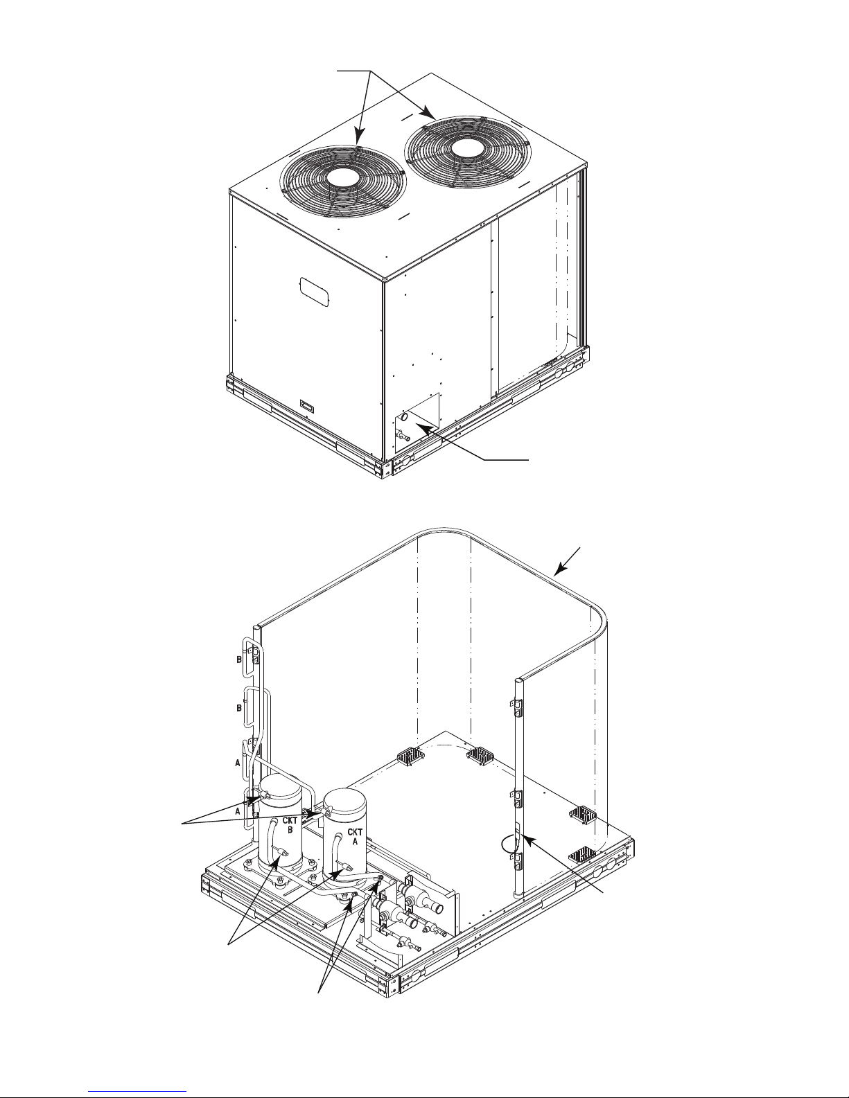
Condenser Fans
HPS
LPS
High Flow
Access Ports
Motormaster
Sensor Location
Outdoor Coil
Service
Valves
Fig. 29 — Typical Exterior, Two-Circuit Unit (38AUD*14 shown)
Fig. 30 — Typical Interior, Two-Circuit Unit (38AUD*14 shown)
32
Page 33

NOVATION™ Coil Cleaning and Maintenance —
To clean the NOVATION condenser coil, chemicals are NOT
to be used; only water is approved as the cleaning solution.
Only clean potable water is authorized for cleaning
NOVATION condensers.
Clean the coil as follows:
1. Turn off unit power.
2. Remove screws holding rear corner posts and top cover
in place. Pivot top cover up 305 to 457 mm (12 to 18 in.)
and support with a rigid support. See Fig. 31
Fig. 31 — Pivot and Support Top Cover
3. Carefully remove any foreign objects or debris attached
to the coil face or trapped within the mounting frame and
brackets.
4. Using a high pressure water sprayer, purge any soap or
industrial cleaners from hose and/or dilution tank prior to
wetting the coil.Clean condenser face by spraying the coil
core steadily and uniformly from top to bottom, directing
the spray straight into or toward the coil face. Do not
exceed 900 psig or a 45 degree angle; nozzle must be at
least 30 cm (12 in.) from the coil face. Reduce pressure
and use caution to prevent damage to air centers (fins).
Do not fracture the braze between air centers and
refrigerant tubes. Allow water to drain from the coil core
and check for refrigerant leaks prior to start−up.
5. Replace top cover and rear corner posts.
EQUIPMENT DAMAGE HAZARD
Failure to follow this caution may result in damage to
equipment.
Chemical cleaning should NOT be used on the aluminum
microchannel (NOVATION) condenser. Damage to the coil
may occur. Only approved cleaning is recommended.
Repairing NOVATION Condenser Tube Leaks
RCD offers service repair kit Part Number 50TJ660007 for
repairing tube leaks in the NOVATION coil crosstubes. This kit
includes approved braze materials (aluminum fluxcore braze
rods), a heat shield, a stainless steel brush, replacement fin
segments, adhesive for replacing fin segments, and instructions
specific to the NOVATION aluminum coil. See EPIC for
instruction sheet 99TA526379.
The repair procedure requires the use of MAPP gas and torch
(must be supplied by servicer) instead of conventional
oxyacetylene fuel and torch. While the flame temperature for
MAPP is lower than that of oxyacetylene (and thus provides
more flexibility when working on aluminum), the flame
temperature is still higher than the melting temperature of
aluminum, so user caution is required. Follow instructions
carefully. Use the heat shield.
Replacing NOVATION Condenser Coil
The service replacement coil is preformed and is equipped with
transition joints with copper stub tubes. When brazing the
connection joints to the unit tubing, use a wet cloth around the
aluminum tube at the transition joint. Avoid applying torch
flame directly onto the aluminum tubing.
Service Parts
Listings of service parts for all units are available from the Replacement Components Division’s Electronic Parts Information Catalog (EPIC). EPIC is available at Totaline stores, distributor and service office parts departments and on-line at
HVACPartners.com.
When entering EPIC, the full unit model number is required.
The model number includes the Design Revision reference value (see Fig. 2, Position 13). The unit model number is available
from the unit’s information data plate. (Do not use the “catalog
number” when using EPIC. The “catalog number” suppresses
the Design Revision value; failure to include Design Revision
value may cause an incorrect unit parts list to be displayed.)
When using EPIC, enter first four digits of the model number
only. Find appropriate model from sales packages listed. Be
sure to choose correct voltage and Design Revision.
EPIC is a product of RCD. To comment of the EPIC program,
use the “Comment” button inside the EPIC program.
Compressor mounting bolts 734–847 N–cm (65–75 in–lbs)
Condenser fan motor mounting bolts 226 ±23 N–cm (20 ±2 in–lbs)
Condenser fan hub setscrew 949 ±136 N–cm (84 ±2 in–lbs)
High-flow service port 1085 ±23 N–cm (96 ±10 in–lbs)
Schrader-type service check valve 23–34 N–cm (2–3 in–lbs)
FASTENER TORQUE VALUES
Table 15 — Torque Values
33
Page 34
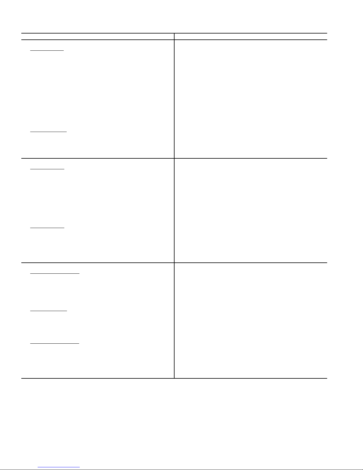
TROUBLESHOOTING
PROBLEM SOLUTION
COMPRESSOR DOES NOT RUN
Contactor Open
1. Power off. 1. Restore power.
2. Fuses blown in field power circuit. 2. After finding cause and correcting, replace with correct size fuse.
3. No control power. 3. Check control transformer primary connections and circuit breaker.
4. Thermostat circuit open. 4. Check thermostat setting.
5. Safety device lockout circuit active. 5. Reset lockout circuit.
6. Low-pressure switch open. 6. Check for refrigerant undercharge, obstruction of indoor airflow.
7. High-pressure switch open. 7. Check for refrigerant overcharge, obstruction of outdoor airflow, air
8. Compressor overtemperature switch open. 8. Check for open condition. Allow for reset. Replace if defective.
9. Loose electrical connections. 9. Tighten all connections.
10. Compressor stuck. 10. See compressor service literature.
Contactor Closed
1. Compressor leads loose. 1. Check connections.
2. Motor windings open. 2. See compressor service literature.
3. Single phasing. 3. Check for blown fuse. Check for loose connection at compressor
COMPRESSOR STOPS ON HIGH-PRESSURE SWITCH
Outdoor Fan On
1. High-pressure switch faulty. 1. Replace switch.
2. Reversed fan rotation. 2. Confirm rotation, correct if necessary.
3. Airflow restricted. 3. Remove obstruction.
4. Air recirculating. 4. Clear airflow area.
5. Noncondensables in system. 5. Recover refrigerant and recharge as required.
6. Refrigerant overcharge. 6. Recover refrigerant as required.
7. Line voltage incorrect. 7. Consult power company.
8. Refrigerant system restrictions. 8. Check or replace filter drier, expansion valve, etc.
Outdoor Fan Off
1. Fan slips on shaft. 1. Tighten fan hub setscrews.
2. Motor not running. 2. Check power and capacitor.
3. Motor bearings stuck. 3. Replace bearings.
4. Motor overload open. 4. Check overload rating. Check for fan blade obstruction.
5. Motor burned out. 5. Replace motor.
COMPRESSOR CYCLES ON LOW-PRESSURE SWITCH
Indoor-Air Fan Running
1. Liquid line solenoid valve(s) fails to open. 1. Check liquid line solenoid valve(s) for proper operation. Replace if
2. Filter drier plugged. 2. Replace filter drier.
3. Expansion valve power head defective. 3. Replace power head.
4. Low refrigerant charge. 4. Add charge. Check low-pressure switch setting.
Airflow Restricted
1. Coil iced up. 1. Check refrigerant charge.
2. Coil dirty. 2. Clean coil fins.
3. Air filters dirty. 3. Clean or replace filters.
4. Dampers closed. 4. Check damper operation and position.
I
ndoor-Air Fan Stopped
1. Electrical connections loose. 1. Tighten all connections.
2. Fan relay defective. 2. Replace relay.
3. Motor overload open. 3. Power supply.
4. Motor defective. 4. Replace motor.
5. Fan belt broken or slipping. 5. Replace or tighten belt.
Make sure liquid line solenoid valve(s) is open.
in system. Be sure outdoor fans are operating correctly.
terminal.
necessary.
34
Page 35
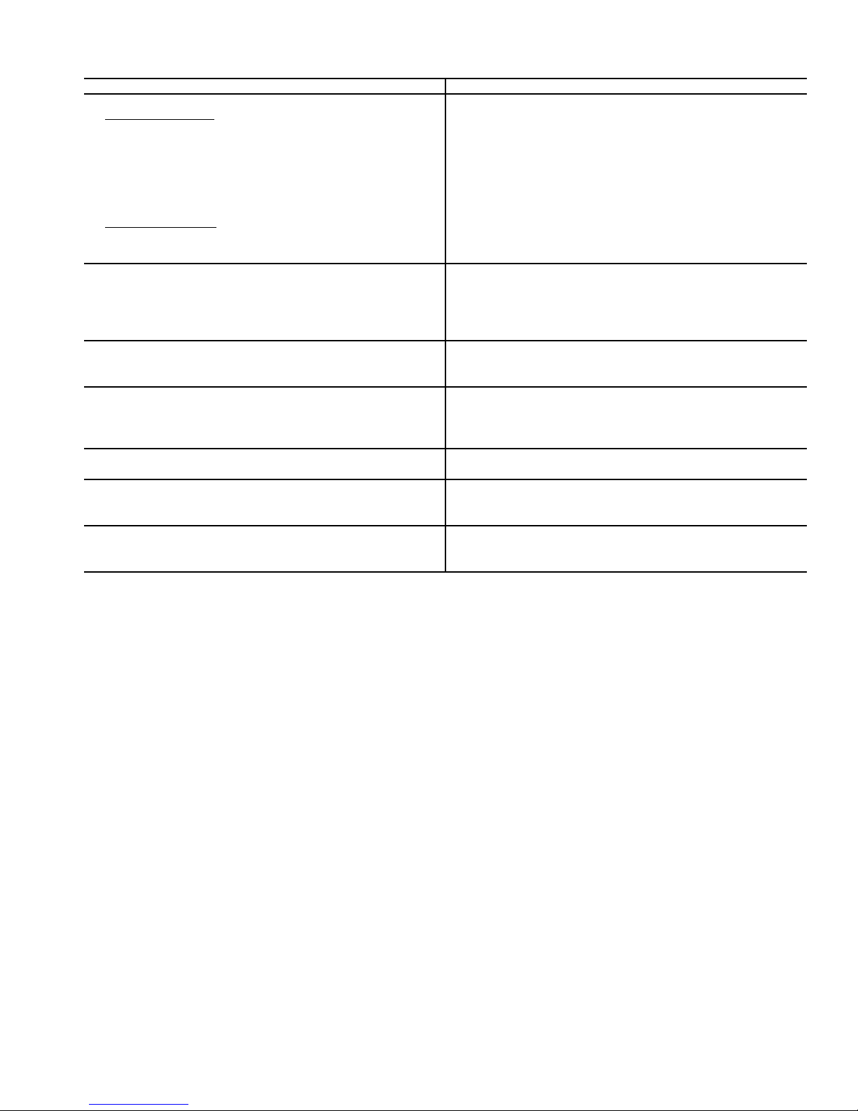
TROUBLESHOOTING (cont)
PROBLEM SOLUTION
COMPRESSOR RUNNING BUT COOLING INSUFFICIENT
Suction Pressure Low
1. Refrigerant charge low. 1. Add refrigerant.
2. Head pressure low. 2. Check refrigerant charge. Check outdoor-air fan thermostat settings.
3. Air filters dirty. 3. Clean or replace filters.
4. Expansion valve power head defective. 4. Replace power head.
5. Indoor coil partially iced. 5. Check low-pressure setting.
6. Indoor airflow restricted. 6. Remove obstruction.
Suction Pressure High
1. Unloaders not functioning 1. Check unloader adjustments. Check unloader setting.
2. Heat load excessive. 2. Check for open doors or windows in vicinity of fan coil.
UNIT OPERATES TOO LONG OR CONTINUOUSLY
1. Low refrigerant charge. 1. Add refrigerant.
2. Control contacts fused. 2. Replace control.
3. Air in system. 3. Purge and evacuate system.
4. Partially plugged expansion valve or filter drier. 4. Clean or replace.
SYSTEM IS NOISY
1. Piping vibration. 1. Support piping as required.
2. Compressor noisy. 2. Replace compressor if bearings are worn.
COMPRESSOR LOSES OIL
1. Leak in system. 1. Repair leak.
2. Crankcase heaters not energized during shutdown. 2. Check wiring and relays. Check heater and replace if defective.
3. Improper interconnecting piping design. 3. Check piping for oil return. Replace if necessary.
FROSTED SUCTION LINE
Expansion valve admitting excess refrigerant. Adjust expansion valve.
HOT LIQUID LINE
1. Shortage of refrigerant due to leak. 1. Repair leak and recharge.
2. Expansion valve opens too wide. 2. Adjust expansion valve.
FROSTED LIQUID LINE
1. Restricted filter drier. 1. Remove restriction or replace.
2. Liquid line solenoid valve partially closed. 2. Replace valve.
35
Page 36
APPENDIX A
AIR CONDITIONER AND HEAT PUMP WITH
PURON
•Puron® (R-410A) refrigerant operates at 50 percent to
•Puron
• Recovery cylinder service pressure rating must be 400
•Puron
• Manifold sets should be 700 psig high side and 180 psig
• Use hoses with 700 psig service pressure rating.
• Leak detectors should be designed to detect HFC
•Puron
• Vacuum pumps will not remove moisture from oil.
• Use only factory specified liquid-line filter driers with
®
— QUICK REFERENCE GUIDE
70 percent higher pressures than R-22. Be sure that
servicing equipment and replacement components are
designed to operate with Puron
®
refrigerant cylinders are rose colored.
®
.
psig, DOT 4BA400 or DOT BW400.
®
systems should be charged with liquid
refrigerant. Use a commercial type metering device in
the manifold hose when charging into suction line with
compressor operating.
low side with 550 psig low-side retard.
refirgerant.
®
, as with other HFCs, is only compatible with
POE oils.
rated working pressures greater than 600 psig.
• Do not install a suction-line filter drier in liquid-line.
• POE oils absorb moisture rapidly. Do not expose oil to
atmosphere.
• POE oils may cause damage to certain plastics and
roofing materials.
• Wrap all filter driers and service valves with wet cloth
when brazing.
• A factory approved, liquid-line filter drier is required on
every unit.
• Do not use an R-22 TXV.
• If indoor unit is equipped with a TXV, it must be
changed to a Puron
®
TXV.
• Never open system to atmosphere while it is under a
vacuum.
• When system must be opened for service, recover
refrigerant, break vacuum with dry nitrogen before
opening system.
• Always replace filter drier after opening system for
service.
• Do not vent Puron
®
into the atmosphere.
• Do not use capillary tube coils.
• Observe all warnings, cautions, and bold text.
•All Puron
• Do not leave Puron
®
heat pumps must have indoor TXV.
®
suction line driers in place for
more than 72 hours.
APPENDIX B
WIRING DIAGRAM LIST
38AU
Size Electrical Characteristics Diagram Number
Z*07 208/230-3-60 38AU500432
Z*08 208/230-3-60 38AU500432
D*12 208/230-3-60 38AU500563
D*14 208/230-3-60 38AU500563
36
Page 37
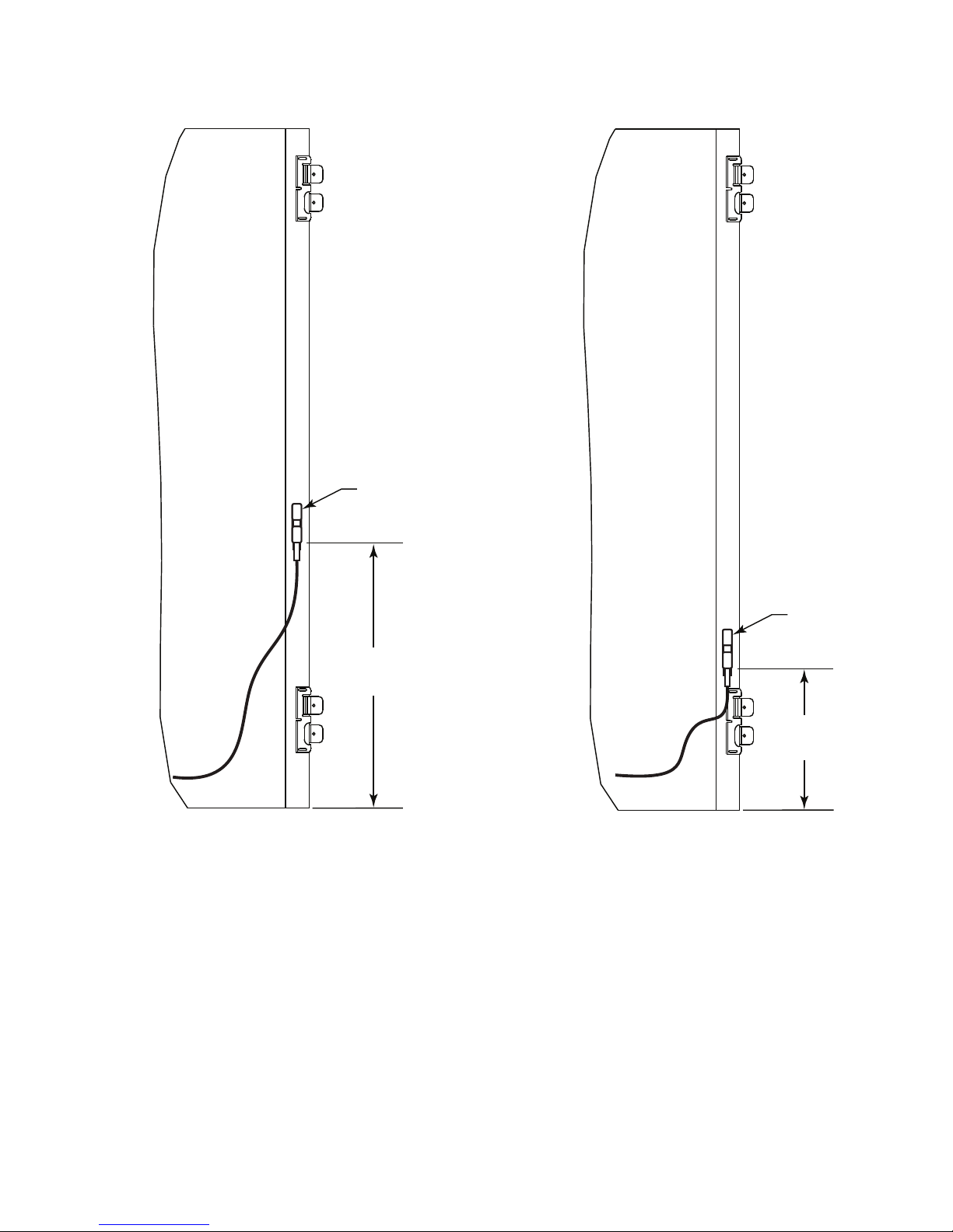
APPENDIX C
508 mm
(20 in)
Sensor
MOTORMASTER SENSOR LOCATIONS
Sensor
254 mm
(10 in)
Fig. 32 — 38AUZ*07-08 Motormaster Sensor Locations Fig. 33 — 38AUD*12-14 Motormaster Sensor Locations
37
Page 38

Copyright 2009 Carrier Corp • 7310 W. Morris St. • Indianapolis, IN 46231 Printed in U.S.A. Edition Date:12/09 Catalog No: 38AU-C01SI
Manufacturer reserves the right to change, at any time, specifications and designs without notice and without obligations. Replaces: New
38
Page 39

III. START UP
START-UP CHECKLIST
I. PRELIMINARY INFORMATION
OUTDOOR: MODEL NO. SERIAL NO.
INDOOR: AIR HANDLER MANUFACTURER
MODEL NO. SERIAL NO.
ADDITIONAL ACCESSORIES
II. PRE-START-UP
OUTDOOR UNIT
IS THERE ANY SHIPPING DAMAGE?
IF SO, WHERE:
WILL THIS DAMAGE PREVENT UNIT START-UP? (Y/N)
CHECK POWER SUPPLY. DOES IT AGREE WITH UNIT? (Y/N)
HAS THE GROUND WIRE BEEN CONNECTED? (Y/N)
HAS THE CIRCUIT PROTECTION BEEN SIZED AND INSTALLED PROPERLY? (Y/N)
ARE THE POWER WIRES TO THE UNIT SIZED AND INSTALLED PROPERLY? (Y/N)
CONTROLS
ARE THERMOSTAT AND INDOOR FAN CONTROL WIRING CONNECTIONS MADE AND CHECKED?
(Y/N)
ARE ALL WIRING TERMINALS (including main power supply) TIGHT? (Y/N)
HAS CRANKCASE HEATER BEEN ENERGIZED FOR 24 HOURS? (Y/N)
(Y/N)
INDOOR UNIT
HAS WATER BEEN PLACED IN DRAIN PAN TO CONFIRM PROPER DRAINAGE? (Y/N)
ARE PROPER AIR FILTERS IN PLACE? (Y/N)
HAVE FAN AND MOTOR PULLEYS BEEN CHECKED FOR PROPER ALIGNMENT? (Y/N)
DO THE FAN BELTS HAVE PROPER TENSION? (Y/N)
HAS CORRECT FAN ROTATION BEEN CONFIRMED? (Y/N)
PIPING
ARE LIQUID LINE SOLENOID VALVES LOCATED AT THE INDOOR COILS AS REQUIRED? (Y/N)
HAVE LEAK CHECKS BEEN MADE AT COMPRESSOR, OUTDOOR AND INDOOR COILS,
TXVs (Thermostatic Expansion Valves), SOLENOID VALVES, FILTER DRIERS, AND FUSIBLE PLUGS
WITH A LEAK DETECTOR? (Y/N)
LOCATE, REPAIR, AND REPORT ANY LEAKS.
HAVE LIQUID LINE SERVICE VALVES BEEN OPENED? (Y/N)
HAVE SUCTION SERVICE VALVES BEEN OPENED? (Y/N)
CHECK VOLTAGE IMBALANCE
LINE-TO-LINE VOLTS: AB
(AB + AC + BC)/3 = AVERAGE VOLTAGE =
MAXIMUM DEVIATION FROM AVERAGE VOLTAGE = V
VOLTAGE IMBALANCE = 100 X (MAX DEVIATION)/(AVERAGE VOLTAGE) =
IF OVER 2% VOLTAGE IMBALANCE, DO NOT ATTEMPT TO START SYSTEM!
CALL LOCAL POWER COMPANY FOR ASSISTANCE.
VAC VBCV
V
CL-1
Page 40
CHECK INDOOR UNIT FAN SPEED AND RECORD.
CHECK OUTDOOR UNIT FAN SPEED AND RECORD.
AFTER AT LEAST 10 MINUTES RUNNING TIME, RECORD THE FOLLOWING MEASUREMENTS:
Circuit A Circuit B
SUCTION PRESSURE
SUCTION LINE TEMP
LIQUID PRESSURE
LIQUID LINE TEMP
ENTERING OUTDOOR UNIT AIR TEMP
LEAVING OUTDOOR UNIT AIR TEMP
INDOOR UNIT ENTERING-AIR DB (dry bulb) TEMP
INDOOR UNIT ENTERING-AIR WB (wet bulb) TEMP
INDOOR UNIT LEAVING-AIR DB TEMP
INDOOR UNIT LEAVING-AIR WB TEMP
COMPRESSOR AMPS (L1/L2/L3) (A/B) / / / /
NOTES:
Copyright 2009 Carrier Corp • 7310 W. Morris St. • Indianapolis, IN 46231 Printed in U.S.A. Edition Date: 12/09 Catalog No: 38AU-C01SI
Manufacturer reserves the right to change, at any time, specifications and designs without notice and without obligations. Pg CL-2 Replaces: New
CUT ALONG DOTTED LINE CUT ALONG DOTTED LINE
- - - - - - - - - - - - - - - - - - - - - - - - - - - - - - - - - - - - - - - - - - - - - - - - - - - - - - - - - - - - - - - - - - - - - - - - - - - - - - - - - - - - - - - - - - - - - - - - - - - - - - - - - - - - - - - - - - - - - - - - - - - - - - - - - - - - - - - - - - - - - - - - - - - - - - - - - - - - - - - - - - - - - - - - - - - - -- - - - - - - - - - - - - - - - - - - -
Page 41

38AUD
Air Cooled Condensing Units
50 Hz
With PuronR(R---410A) Refrigerant
S i z e s 1 6 --- 2 5
Installation, Start---Up and
Service Instructions
CONTENTS
SAFETY CONSIDERATIONS 2....................
INSTALLATION GUIDELINES 2..................
INSTALLATION 7--17...........................
Step 1 -- Plan for Unit Location 8..................
Step 2 -- Complete Pre--Installation Checks 8.........
Step3–PrepareUnitMounting Support 8...........
Step4–RigandMount the Unit 8.................
Step5–CompleteRefrigerantPipingConnections 9...
Step6–InstallAccessories 13....................
Step7–CompleteElectricalConnections 13.........
PRE-START-UP 17...............................
System Check 17...............................
Turn On Crankcase Heater 17.....................
Preliminary Charge 17...........................
START--UP 17--22...............................
38AUD Units 17...............................
OPERATING SEQUENCE 23......................
Indoor (Supply) Fan 23..........................
Cooling, Unit Without Economizer 23..............
Cooling, Unit With Economizer 23.................
Heating 23....................................
ROUTINE SYSTEM MAINTENANCE 24............
Quarterly Inspection
(and 30 days after initial start) 24..................
Seasonal Maintenance 24........................
SERVICE 24--33.................................
Refrigeration System 24.........................
Compressor Oil 24..............................
Servicing Systems on Roofs with
Synthetic Materials 24...........................
Liquid Line Filter Drier 25.......................
Filed Refrigerant Access Ports 25..................
Factory High--Flow Access Ports 25................
Comfort Alert Diagnostic Module 25...............
Crankcase Heater 28............................
Compressor Protection 28........................
Low--Pressure Switches 28.......................
High--Pressure Switches 28.......................
Outdoor Fans 28................................
Lubrication 28.................................
N O VAT I O N tCoil Cleaning and Maintenance 32.....
Repairing NOVATION Condenser Tube Leaks 32.....
Replacing NOVATION Condenser Coil 32...........
Routine Cleaning of Round-Tube Plate Fin
(RTPF) Coils 32................................
Fastener Torque Values 33........................
TROUBLESHOOTING 34--35......................
APPENDIX A
R
Air Conditioner & Heat Pump with Puron
Quick Reference Guide 36........................
APPENDIX B
Wiring Diagram List 36..........................
APPENDIX C
Motormaster Sensor Locations 37..................
START--UP CHECKLIST 39--40....................
—
1
Page 42
SAFETY CONSIDERATIONS
Improper installation, adjustment, alteration, service,
maintenance, or use can cause explosion, fire, electrical
shock or other conditions which may cause personal
injury or property damage. Consult a qualified installer,
service agency, or your distributor or branch for
information or assistance. The qualified installer or
agency must use factory-authorized kits or accessories
when modifying this product. Refer to the individual
instructions package
Follow all safety codes. Wear safety glasses and work
gloves. Use quenching cloths for brazing operations and
have a fire extinguisher available. Read these instructions
thoroughly and follow all warnings or cautions attached to
the unit. Consult local building codes for special
requirements. In absence of local codes, it is
recommended that the USA standard ANSI/NFPA 70,
National Electrical Code (NEC), be followed.
38AUD
It is important to recognize safety information. This is the
safety-alert symbol . When you see this symbol on the
unit and in instructions or manuals, be alert to the
potential for personal injury.
Understand the signal words DANGER, WARNING,
CAUTION, and NOTE. These words are used with the
safety-alert symbol. DANGER identifies the most serious
hazards which will result in severe personal injury or
death. WARNING signifies hazards which could result in
personal injury or death. CAUTION is used to identify
unsafe practices, which may result in minor personal
injury or product and property damage. NOTE is used to
highlight suggestions which will result in enhanced
installation, reliability, or operation.
!
WARNING
ELECTRICAL SHOCK HAZARD
Failure to follow this warning could cause in personal
injury or death.
Before performing service or maintenance operations
on unit, always turn off main power switch to unit and
install lockout tag. Unit may have more than one
power switch.
!
WARNING
UNIT OPERATION AND SAFETY HAZARD
Failure to follow this warning could cause in personal
injury,death and/or equipment damage.
R
Puron
higher pressures than standard R--22 systems. Do not
use R--22 service equipment or components on Puron
refrigerant equipment.
(R--410A) refrigerant systems operate at
!
WARNING
PERSONAL INJURY AND ENVIRONMENTAL
HAZARD
Failure to follow this warning could cause in personal
injury or death.
Relieve pressure and recover all refrigerant before
system repair or final unit disposal.
Wear safety glasses and gloves when handling
refrigerants. Keep torches and other ignition sources
away from refrigerants and oils.
!
CUT HAZARD
Failure to follow this caution may result in personal
injury.
Sheet metal parts may have sharp edges or burrs. Use
care and wear appropriate protective clothing, safety
glasses and gloves when handling parts and servicing
38AUD units.
CAUTION
INSTALLATION GUIDELINE
Replacement /Retrofit – R22 to Puron
Replacement/retrofit installations require change-out of
outdoor unit, metering device, and filter driers.
Change-out of indoor coil (evaporator) and
interconnecting tubing is recommended.
Existing evaporator coil – If the existing evaporator coil
may be re-used, check with the coil manufacturer to verify
the coil construction is suitable for operation with the
higher pressures of Puron
the existing TXV valve is compatible with R-410A,
replace if necessary. The minimum factory test pressure
rating must be 1725 kPa (250 psig). Existing coil will
need to be purged with Nitrogen to remove as much
mineral oil as possible to eliminate cross contamination of
oils.
Acid test – If the existing system is being replaced
because of a compressor electrical failure, assume acid is
in system. If system is being replaced for any other
reason, use an approved acid test kit to determine acid
level. If even low levels of acid are detected, install a 100
percent activated alumina suction-line filter drier in
addition to the replacement liquid-line filter drier.
Remove the suction line filter drier as soon as possible,
with a maximum of 72 hr of operation. Recommendation:
Install a ball valve in the liquid line at the filter drier
location when installing a suction filter in the suction line.
R
(R-410A). Also determine if
R
2
Page 43
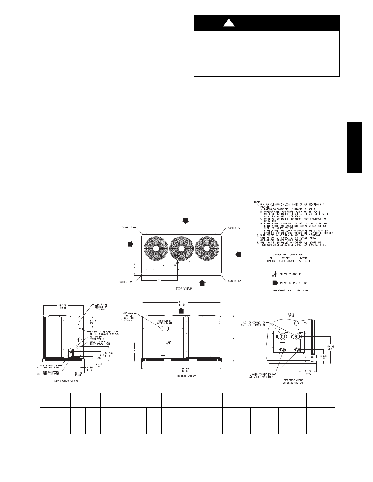
Installation –
1. Remove the existing evaporator coil or fan coil and
install the replacement coil when appropriate.
2. Drain oil from low points and traps in suction line
tubing (and hot gas bypass tubing if appropriate) and
evaporator if they were not replaced. Removing oil
from evaporator coil may require purging of the
tubing with dry nitrogen.
3. Unless indoor unit is equipped with a Puron® approved metering device, change the metering device
to a thermal expansion valve (TXV) designed for
R
Puron
(R-410A).
4. Remove the existing outdoor unit. Install the new outdoor unit according to these installation instructions.
5. Install a new field-supplied liquid-line filter drier at
the indoor coil just upstream of the TXV or fix orifice
metering device.
6. If a suction line filter drier is also to be installed, install suction line drier downstream of suction line service valve at condensing unit.
!
CAUTION
UNIT DAMAGE HAZARD
Failure to follow this caution may result in equipment
damage or improper operation.
Never install suction--line filter drier in the liquid--line
of a Puron
R
system.
7. If required, install a 100% activated alumina suction
line filter drier at the outdoor unit.
8. Evacuate and charge the system according to the instructions in this installation manual.
9. Operate the system for 10 hr. Monitor the pressure
drop across the suction line filter drier. If pressure
drop exceeds 21kPa (3 psig), replace suction-line and
liquid-line filter driers. Be sure to purge system with
dry nitrogen and evacuate when replacing filter
driers. Continue to monitor the pressure drop across
suction-line filter drier. Repeat filter changes is necessary. Never leave suction-line filter drier in system
longer than 72 hr (actual time).
38AUD
UNIT
38AUD*16 288 633 100 210 61 134 61.5 135 65.5 144
Standard
Weight
kg. lbs. kg. lbs. kg. lbs. kg. lbs. kg. lbs. X Y Z H
Corner
A
Corner
B
Corner
C
Corner
D
965.2 mm
38.00 in
Fig. 1 -- 38AUD*16 Unit Dimensions
3
Center of Gravity
495.3 mm
19.50 in
383.3 mm
15.10 in
C10065
Unit
Height
279.2 mm
50.36 in1
Page 44
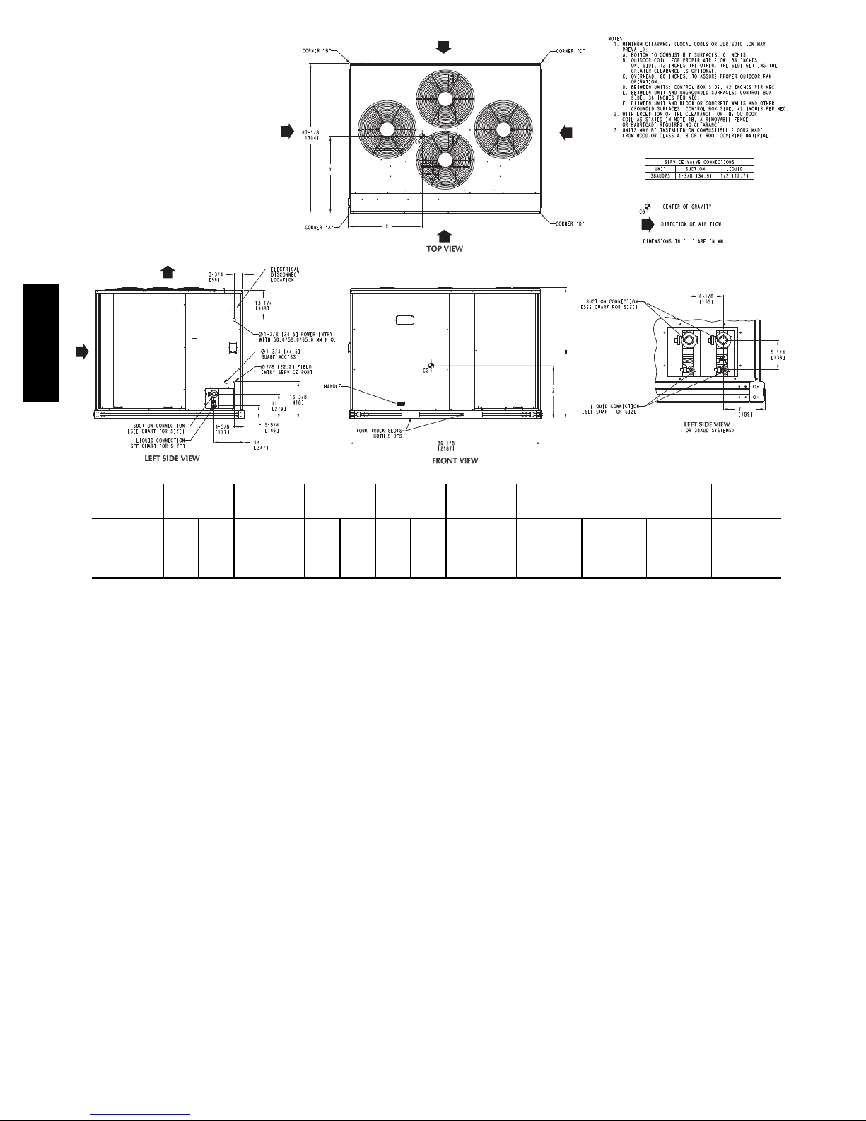
38AUD
C10066
UNIT
38AUD*25 409 900 216 475 26.5 58 110 242 57 125
Standard
Weight
kg. lbs. lbs. kg. kg. lbs. kg. lbs. kg. lbs. X Y Z H
Corner
A
Corner
B
Corner
C
Corner
D
946.1 mm
37.25 in
Center of Gravity
590.5 mm
23.25 in
383.3 mm
15.10 in
Unit
Height
1279.2 mm
50.36 in
Fig. 2 -- 38AUD*25 Unit Dimensions
4
Page 45
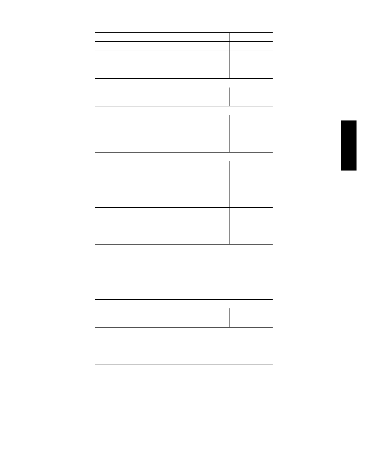
Table 1A — Physical Data — 38AUD*16-25 Units — 50 Hz SI
UNIT SIZE 38AU D*16 D*25
NOMINAL CAPACITY (kW) 52.7 70.3
OPERATING WEIGHT (kg)
NOVATION™ Coil (Al Tube) 288
Round Tube/Plate Fin Coil (Cu/Al) 409
REFRIGERANT TYPE
Operating Charge A/B, Typical (kg)
Shipping Charge A/B (kg) 2.7/2.7 8.6/8.6
COMPRESSOR Scroll
Qty...Model 2...ZP83 2...ZP103
Oil Charge (L) 1.7 3.2
No. Cylinders N/A N/A
Speed (r/s) 58 58
CONDENSER FANS
Qty...r/s 3...18 4...18
Motor Hp NEMA
Diameter (mm) 560 560
Nominal Airflow (L/s) 3933 5506
Watts (Total) 810 960
CONDENSER COIL (Qty) 2...NOVATION 2...RTPF
Face Area (sq m total) 4.6 4.6
Rows/Fins per Meter (Fins/m) 1...670 2...670
Storage Capacity A/B (kg)** 3.0/3.0 9.5/9.5
CONTROLS
Pressurestat Settings (kPa)
High Cutout 4347 ± 70
Cut-in 3482 ±138
Low Cutout 372 ± 21
Cut-in 807 ± 34
PIPING CONNECTIONS (mm ODS)
Qty...Suction 2...34.93 2...34.93
Qty...Liquid 2...12.7 2...12.7
LEGEND
NEMA — National Electrical Manufacturers Association
ODS — Outside Diameter Sweat (socket)
‡
Unit is factory-supplied with partial charge only.
†
Typical operating charge with 7.62 m of interconnecting piping.
** Storage capacity of condenser coil with coil 80% full of liquid R-410A at 35°C.
‡
†
6.4/6.4 9.5/9.5
R-410A
1
/
4
1
/
4
38AUD
5
Page 46

Table 1B — Physical Data — 38AUD*16-25 Units — 50 Hz English
UNIT SIZE 38AU D*16 D*25
NOMINAL CAPACITY (tons) 15 20
OPERATING WEIGHTS (lb)
NOVATION™ Coil (Al Tube) 633
Round Tube/Plate Fin Coil (Cu/Al) 900
REFRIGERANT TYPE
Operating Charge A/B, Typical (lb)
Shipping Charge A/B (lb) 6.0/6.0 19.0/19.0
COMPRESSOR Scroll
Qty...Model 2...ZP83 2...ZP103
Oil Charge (oz) 60 110
No. Cylinders N/A N/A
Speed (rpm) 3500 3500
38AUD
CONDENSER FANS
Qty...Rpm 3...1100 4...1100
Motor Hp
Diameter 22 22
Nominal Airflow (Cfm Total) 8,300 11,700
Watts (Total) 810 960
CONDENSER COIL (Qty) 2...NOVATION 2...RTPF
Face Area (sq ft total) 50 50
Rows/Fins per inch (FPI) 1/17 2/17
Storage Capacity A/B (lb)** 6.7/6.7 21.0/21.0
CONTROLS
Pressurestat Settings (psig)
High Cutout 630 ± 10
Cut-in 505 ± 20
Low Cutout 54 ± 3
Cut-in 117 ± 5
PIPING CONNECTIONS (in. ODS)
Qty...Suction 2...13/
Qty...Liquid 2...1/
LEGEND
ODS — Outside Diameter Sweat (socket)
‡
Unit is factory-supplied with partial charge only.
†
Typical operating charge with 25 ft of interconnecting piping.
** Storage capacity of condenser coil with coil 80% full of liquid R-410A at 95°F.
‡
†
14.0/14.0 21.0/21.0
R-410A
1
/4
8
2
1
/
4
2...13/
2...1/
8
2
6
Page 47
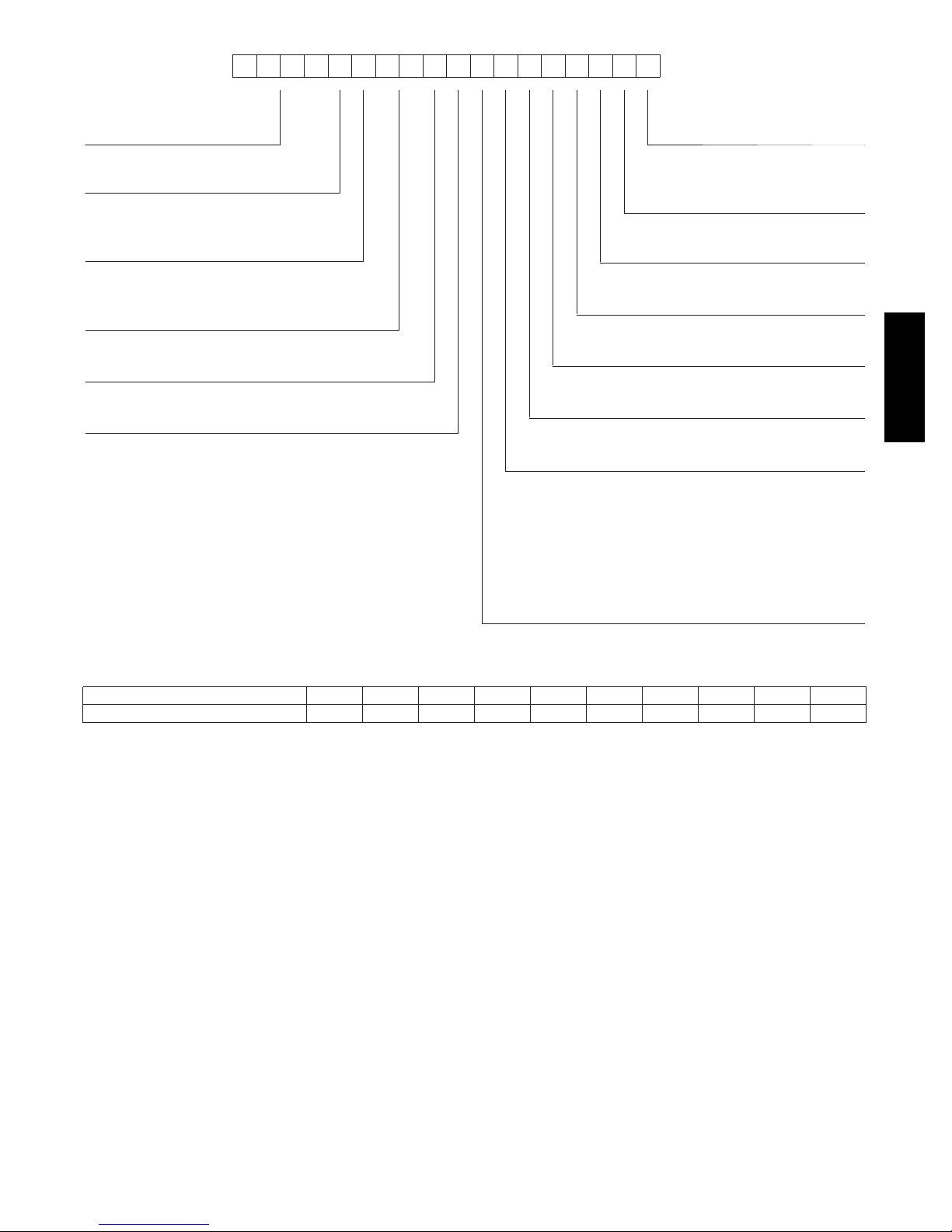
1 2 3 4 5 6 7 8 9 10 11 12 13 14 15 16 17 18
3 8 A U D A 2 5 A 0
_____________ ____
Model Type Packaging
38AU= C arrier Condensing Unit
Puronr R ---410A Refrigerant
9 A 0 A 0 A 0
G
0=Standard
1=LTL
Typ e of C oi l
D = Dual Circuit, A/C Scroll Compressor
Refrigerant Options
A = None
B = Low Ambient
Nominal Capacity
16 = 45 kW (15 Tons)
25 = 57 kW (20 Tons)
Not Used
A=Not Used
Not Used
0=Not Used
Not Used
A=PlaceHolder
Base Unit Controls
0 = Electro-Mechanical Controls
Design Rev
A = Initial Release
Voltage
9 = 400/3/50
Coil Options
Size 16 (NOVATION™)
G= Al/Al
K = E-Coat Al/Al
T = Al/Al with Hail Guard
W= E-Coat Al/Al with Hail Guard
Fig. 3 -- Model Number Nomenclature
Electrical Options
A=None
C = Non-Fused Disconnect
Service Options
0=None
38AUD
Size 25 (RTPF)
A= Cu/Al
B = Precoat (Cu/Al)
C = E-Coat (Cu/Al)
M= Cu/Al with Hail Guard
N = Precoat (Cu/Al) with Hail Guard
P = E-Coat (Cu/Al) with Hail Guard
C10067
POSITION NUMBER
TYPICAL
12345678910
0510G12345
Fig. 4 -- Serial Number Nomenclature
Matching 38AUD To Evaporator Coil –
The Model 38AUD is a dual-circuit unit design that
requires two sets of refrigeration piping between the
outdoor unit and the evaporator coil (or coils). This model
can only be connected to an evaporator coil that has two
refrigeration circuits (or to two separate evaporator coils).
The Model 38AUD CANNOT be connected to a
single-circuit evaporator coil. The Model 38AUD
CANNOT be field-converted to a single-circuit design.
Before unpacking this new 38AUD model, compare the
evaporator coil design to the 38AUD model.
SETANGISEDNOITISOP
)radnelac lacsif( erutcafunam fo keeW1−2
Year of manufacture (”10” = 2010)3−4
)ASU ,saxeT ,PTE = G( noitacol gnirutcafunaM5
rebmun laitneuqeS6−10
C10068
.INSTALLATION
Jobsite Survey
Complete the following checks before installation.
1. Consult local building codes or the U.S.A. National
Electrical Code (Ref: ANSI/NFPA 70, [American National Standards Institute/National Fire Protection Association], latest revision) for special installation requirements
2. Determine unit location (from project plans) or select
unit location.
3. Check for possible overhead obstructions which may
interfere with unit lifting or rigging.
7
Page 48
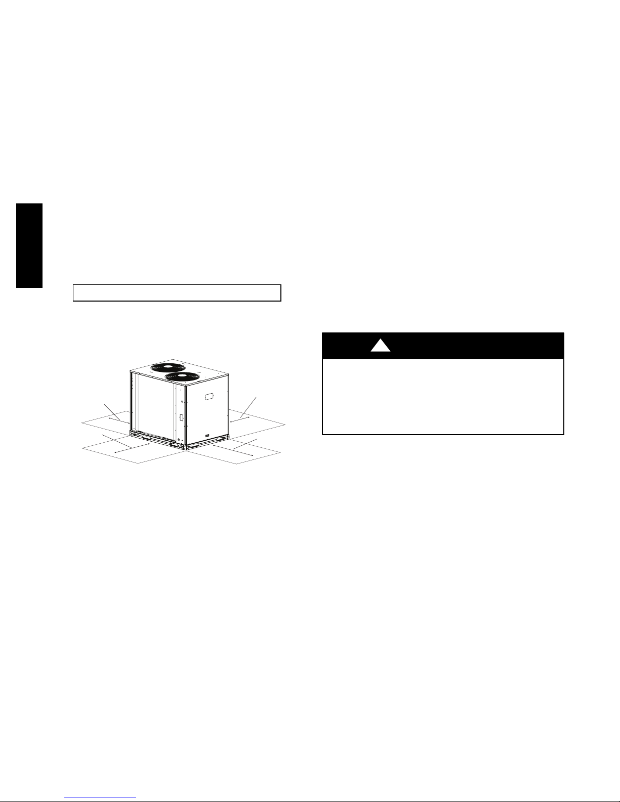
Step 1 — Plan for Unit Location
Select a location for the unit and its support system (pad,
rails or other) that provides for the minimum clearances
required for safety. This includes the clearance to
combustible surfaces, unit performance and service access
below, around and above unit as specified in unit
drawings. See Fig. 5.
NOTE: Consider also the effect of adjacent units on
airflow performance and control box safety clearance.
Do not install the outdoor unit in an area where fresh air
supply to the outdoor coil may be restricted or when
recirculation from the condenser fan discharge is possible.
Do not locate the unit in a well or next to high walls.
Evaluate the path and required line length for
interconnecting refrigeration piping, including suction
riser requirements (outdoor unit above indoor unit), liquid
line lift (outdoor unit below indoor unit) and hot gas
bypass line. Relocate sections to minimize the length of
38AUD
interconnecting tubing.
DO NOT BURY REFRIGERATION LINES.
S Allow sufficient space for airflow clearance, wiring,
refrigerant piping, and servicing unit. See Fig. 1 and
Fig. 2 for unit dimensions and weight distribution data.
S Locate the unit so that the outdoor coil (condenser)
airflow is unrestricted on all sides and above.
S The unit may be mounted on a level pad directly on the
base channels or mounted on raised pads at support
points. See Tables 1A and 1B for unit operating
weights. See Fig. 1 and Fig. 2 for weight distribution
based on recommended support points.
NOTE: If vibration isolators are required for a particular
installation, use the data in Fig. 1 and Fig. 2 to make the
proper selection.
Step 3 — Prepare Unit Mounting Support
Slab Mount —
Provide a level concrete slab that extends a minimum of
150 mm (6 in.) beyond unit cabinet. Install a gravel apron
in front of condenser coil air inlet to prevent grass and
foliage from obstructing airflow.
Although unit is weatherproof, avoid locations that permit
water from higher level runoff and overhangs to fall onto
the unit.
RIGHT:
REAR:
Min 18” (457 mm)
requried for service
LEFT:
Min 18” (457 mm)
requried for service
Note: Observe requirements for 39” (914 mm) operating clearance
on either Left or Rear coil opening.
Min 18” (457 mm)
requried for service
FRONT:
42” (1067 mm)
C10069
Fig. 5 -- Service Clearance Dimensional Drawing
Step 2 — Complete Pre-Installation Checks
CHECK UNIT ELECTRICAL CHARACTERISTIC —
Confirm before installation of unit that voltage, amperage
and circuit protection requirements listed on unit data plate
agree with power supply provided.
UNCRATE UNIT — Remove unit packaging except for
the top skid assembly, which should be left in place until
after the unit is rigged into its final location.
INSPECT SHIPMENT — File a claim with shipping
company if the shipment is damaged or incomplete.
CONSIDER SYSTEM REQUIREMENTS
S Consult local building codes or the U.S.A. National
Electrical Code (Ref: ANSI/NFPA 70, [American
National Standards Institute/National Fire Protection
Association], latest revision) for special installation
requirements.
Step 4 — Rig and Mount the Unit
!
UNIT DAMAGE HAZARD
Failure to follow this caution may result in equipment
damage.
All panels must be in place when rigging. Unit is not
designed for handling by fork truck.
RIGGING — These units are designed for overhead
rigging. Refer to the rigging label for preferred rigging
method. Spreader bars are not required if top crating is
left on the unit. All panels must be in place when rigging.
As further protection for coil faces, plywood sheets may
be placed against the sides of the unit, behind cables. Run
cables to a central suspension point so that the angle from
the horizontal is not less than 45 degrees. Raise and set
the unit down carefully.
If it is necessary to roll the unit into position, mount the
unit on longitudinal rails, using a minimum of 3 rollers.
Apply force to the rails, not the unit. If the unit is to be
skidded into position, place it on a large pad and drag it
by the pad. Do not apply any force to the unit.
Raise from above to lift the unit from the rails or pad
when unit is in its final position.
After the unit is in position, remove all shipping materials
and top crating.
CAUTION
8
Page 49

Step 5 — Complete Refrigerant Piping
Connections
IMPORTANT: Do not bury refrigerant piping
underground.
IMPORTANT: A refrigerant receiver is not provided
with the unit. Do not install a receiver.
PROVIDE SAFETY RELIEF — If local codes dictate an
additional safety relief device, purchase locally and install
locally. Installation will require the recovery of the factory
shipping charge before the factory tubing can be cut and
the supplemental relief device is installed.
The 38AUD has two separate refrigeration systems. If
required, each circuit will require a field-supplied/installed
supplemental relief device.
Table 3 – Equivalent Lengths for Common Fittings (ft)
Nominal
Tube O D
3
/
8
1
/
2
5
/
8
3
/
4
7/
8
11/
8
13/
8
15/
8
21/
8
Nominal
Tube O D
3
/
8
1
/
2
5
/
8
3
/
4
7/
8
11/
8
13/
8
15/
8
21/
8
90° Std 90° Lrad 90° Street 45° Std 45° Street
1.3 0.8 2.2 0.6 1
1.4 0.9 2.3 0.7 1.1
1.6 1 2.5 0.8 1.3
1.8 1.2 2.9 0.9 1.5
2 1.4 3.2 0.9 1.6
2.6 1.7 4.1 1.3 2.1
3.3 2.3 5.6 1.7 3
4 2.6 6.3 2.1 3.4
5 3.3 8.2 2.6 4.5
Branch
Flow
2.6 0.8 1.1 1.3
2.7 0.9 1.2 1.4
3.5 1.2 1.7 1.8
10 3.3 4.7 5
No Reduct Reduce 25% Reduce 50%
3 1 1.4 1.6
4 1.4 1.9 2
5 1.7 2.3 2.6
7 2.3 3.1 3.3
8 2.6 3.7 4
Elbows
Tees
Straight-Thru
CHECK 38AUD UNIT WITH EVAPORATOR COIL
CONNECTIONS — Confirm before installation of unit
that the evaporator coil connections are consistent with
this 38AUD unit.
DETERMINE REFRIGERANT LINE SIZES — Select
the recommended line sizes for the 38AUD unit. See
Tables 3 and 4.
Determine the linear length of interconnecting piping
required between the outdoor unit and indoor unit
(evaporator). Consider and identify also the arrangement
of the tubing path (quantity and type of elbows in both
lines), liquid line solenoid size, filter drier and any other
refrigeration specialties located in the liquid line. Refer to
the indoor unit installation instructions for additional
details on refrigeration specialties devices.
Determine equivalent line length adjustments for path and
components and add to linear line lengths. See Table 4,
Equivalent Lengths for Common Fittings, for usual fitting
types. Also identify adjustments for refrigeration
specialties. Refer to Part 3 of the Carrier System Design
Manual for additional data and information on equivalent
lengths.
NOTE: Equivalent line lengths will vary based on tube
diameter. Calculate equivalent line length for each pipe by
adding equivalent length adjustments to linear lengths for
each pipe.
Liquid Lift – A liquid lift condition exists when the
outdoor unit is located below the indoor (evaporator) unit
and liquid flows vertically up in a portion of the liquid
line. The vertical column of liquid reduces the available
state point subcooling at the evaporator coil’s thermal
expansion valve. This effect reduces the length of liquid
lift (meters [feet] of elevation) that a liquid line size can
accommodate. Longer linear tube lengths will also reduce
the amount of liquid lift possible.
Check Tables 4 for maximum liquid lift capabilities for
line sizes. Reselect the liquid line tube size if necessary. If
maximum available tube size cannot provide the required
lift distance on this installation, relocate the outdoor unit
to reduce the equivalent line length or the lift requirement.
Suction Riser – A suction riser condition exists when the
outdoor unit is located above the indoor (evaporator) unit
and suction vapor must flow vertically up to return to the
compressor. Oil return is a concern when the suction tube
size is too large to produce the minimum refrigerant
velocity to ensure oil return at minimum load conditions.
38AUD
Check Table 5 for maximum suction tube size for 38AUD
units at minimum load conditions. Consider suction speed
riser (reduced tube size for vertical segment only) or
double suction riser arrangement if the recommended
suction tube size does not provide necessary minimum
flowrates for this riser.
9
Page 50
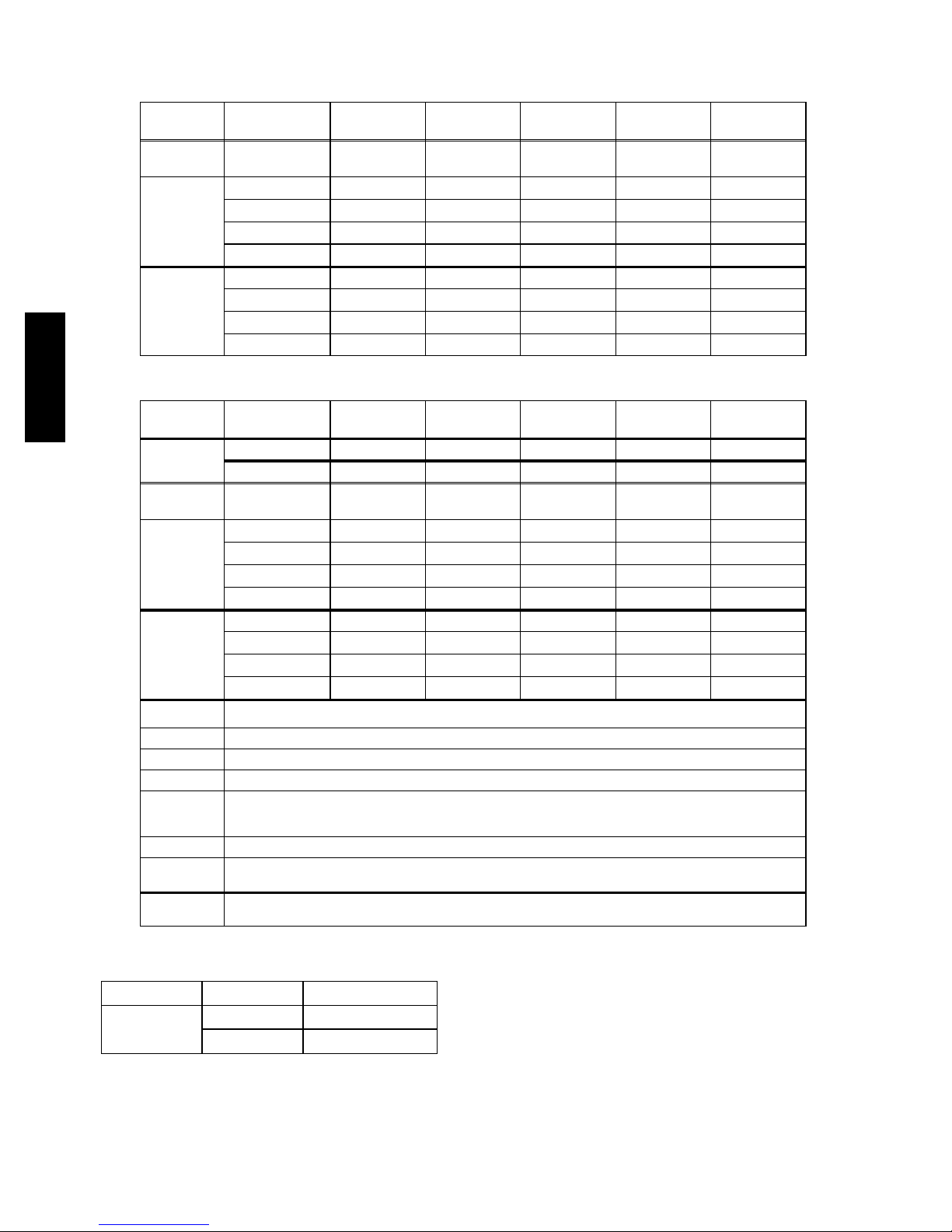
Table 4 – 38AUD 15-25 Piping Recommendations (Two-Circuit Unit)
SI
NOTE: 38AUD requires TWO sets of refrigeration piping
R-410A
Model Linear
38AUD*16 Liquid Line
38AUD*25 Liquid Line
English
38AUD
NOTE: 38AUD requires TWO sets of refrigeration piping
R-410A
Model Linear
38AUD*16 Liquid Line
38AUD*25 Liquid Line
Equivalent
Length m
Length m
0-12 12-23 23-34 34-46 46-57
0 --- 7 . 5 7.5---15 15 ---23 23--- 30 30---38
3
/
8
3
/
8
3
1
/
8
3
/
2
1
/
8
1
/
/
2
2
Max Lift 7.5 15 22 23 13 30 38
Suction Line
7
/
8
7
/
8
11/
8
11/
8
11/
8
Charge (kg) A/B 5.9 6.3 7.0 8.0 7.5 8.9 9.8
1
/
2
1
/
2
1
/
2
1
5
/
2
1
/
8
5
/
/
2
8
Max Lift 7.5 15 23 20 28 23 33
Suction Line
7
/
8
11/
8
11/
8
11/
8
13/
8
Charge (kg) A/B 9.4 10.3 11.2 12.1 13.8 13.0 15.1
Equivalent
Length
ft 0 --- 1 2 38--- 75 75 ---113 113 ---150 150--- 188
m 0 --- 7 . 5 7.5--- 15 15---23 23---30 46-57
Length ft
0 --- 2 5 25 ---50 50--- 75 75 ---100 100--- 125
3
/
8
3
/
8
3
1
/
8
3
/
2
1
/
8
1
/
/
2
2
Max Lift 25 50 71 75 43 100 125
Suction Line
7
/
8
7
/
8
11/
8
11/
8
11/
8
Charge (lbs) A/B 12.9 13.9 15.4 17.7 16.5 19.6 21.6
1
/
2
1
/
2
1
/
2
1
5
/
2
1
/
8
5
/
/
2
8
Max Lift 7.5 15 23 20 28 23 33
Suction Line
7
/
8
11/
8
11/
8
11/
8
13/
8
Charge (lbs) A/B 20.7 22.8 24.7 26.6 30.4 28.6 33.3
Legend:
Equiv Length Equivalent tubing length, including effects of refrigeration specialties devices
Linear Length Typical linear tubing length, (50% added to linear to define Equivalent Length for this table)
Liquid Line Tubing size, inches OD.
Max Lift Maximum liquid lift (indoor unit ABOVE outdoor unit only), at maximum permitted liquid line pressure drop —
Suction Line Tube size, inches OD
Charge Charge Quantity, kg (lbs). Calculated for both liquid line sizes (where applicable), but only with larger suction line size
NOTE: For applications with equivalent length greater than 57 m (188 ft) and/or linear length greater than 38 m (125 ft),
S Linear Length Less than 30 m (100 ft): Minimum 1.1°C(2.0°F) subcooling entering TXV
S Linear Length Greater than 30 m (100 ft): Minimum 0.3°C(0.5°F) subcooling entering TXV
(where applicable)
contact your local Carrier representative.
Ta bl e 5 – 38AUD Maximum Suction Pipe Size
Model: Unit Size Maximum Tube Size
38AUD
16 15/
25 15/
8
8
INSULATE SUCTION LINES — Apply closed-cell
tubular insulation to all suction lines between evaporator
coil connection and 38AUD unit’s suction service valve.
Hot Gas Bypass — Hot gas bypass, if used, should be
introduced before the evaporator. (A bypass route that also
bypasses the evaporator circuit may lead to oil trapping in
the evaporator circuit during low load conditions and then
to oil slugging as evaporator load increases.) Model
38AUD units do not include a hot gas stub connection; a
tee must be field-supplied and installed in the compressor
1
discharge line. Run a
/2-in OD line between outdoor unit
and evaporator coil inlet. Install an Auxiliary Side
Connector at the evaporator between TXV and distributor
(follow instructions for the side connector part). Insulate
the hot gas line.
10
Page 51
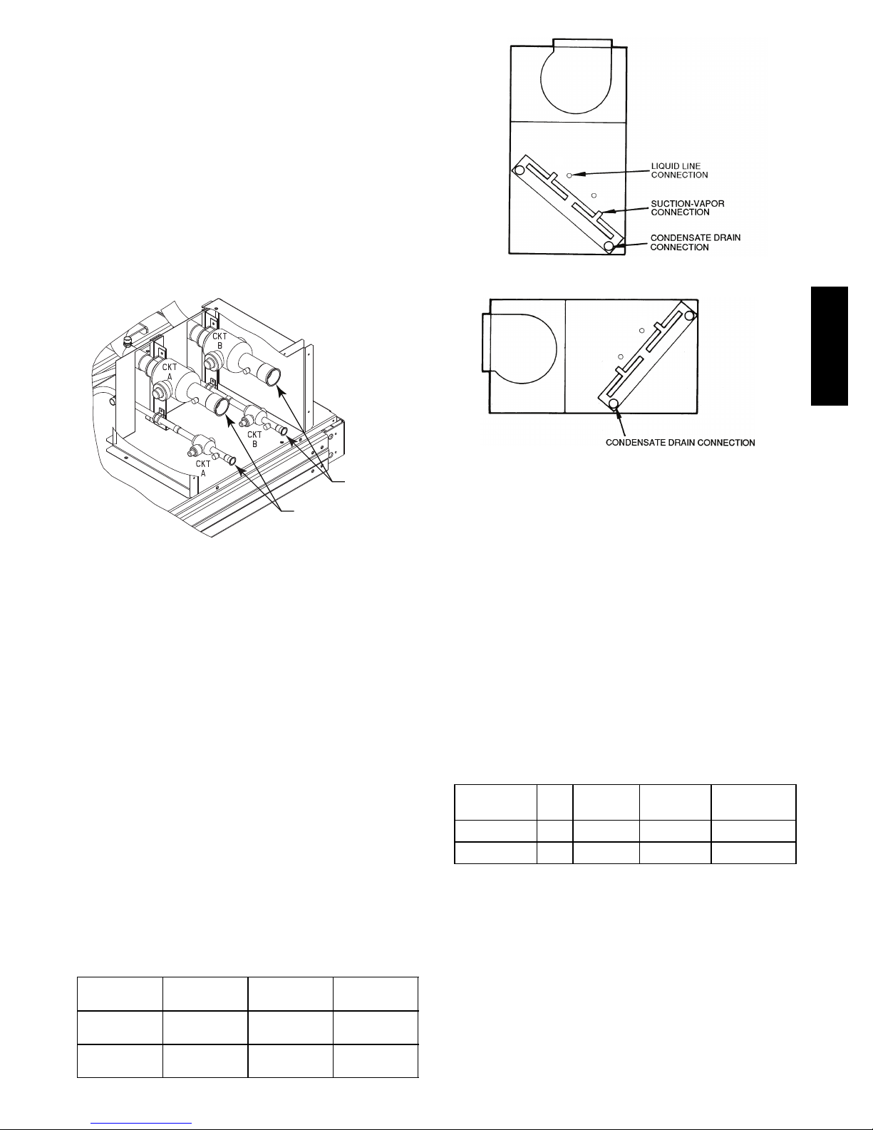
Generally only one hot gas bypass system will be applied
on a two-circuit unit. Connect the hot gas bypass system
to Circuit 1 (first-on/last-off, connected to the evaporator
coil’s bottom circuit).
38AUD PIPING CONNECTIONS – The 38AUD’s two
circuits are designated Circuit 1 and Circuit 2. Circuit 1 is
controlled by the thermostat’s Y1 (or TC1) contact and
will be the first circuit on and last circuit off. Circuit 2 is
controlled by the thermostat’s Y2 (or TC2) contact and
this circuit is always the “lag” circuit.
See Fig. 6 for location of Circuit 1 and Circuit 2 service
valves and field piping connections. Circuit 1 is on the
left-hand side of the service valve compartment; Circuit 2 is
on the right.
1
2
FIRS T ON/LA ST OFF = 2
VERTICAL INSTALLATION
2
Circuit B
Connections
Circuit A
Connections
C10070
Fig. 6 -- 38AUD Service Valve Locations
When a single piece evaporator coil with two separate
circuits is connected to a 38AUD, the lower coil circuit
should be connected to the 38AUD’s Circuit 1 so that the
evaporator’s lower coil segment is first-on/last-off (to avoid
re-evaporation of condensate on dry lower coil segments).
Plan the Circuit 1 and Circuit 2 tubing segments carefully,
mark each segment and check constantly as piping
systems are assembled to avoid piping errors.
38AUD unit cannot be field-piped as a
single-circuit/tandem system.
1
FIRS T ON /LAST OF F = 1
HORIZONTAL INSTALLATION
C10071
Fig. 7 -- Typical Evaporator Coil Connections (40RU)
INSTALL FILTER DRIERS AND MOISTURE
INDICATORS — Every unit MUST have a filter drier in
the liquid line. 38AUD models require two filter driers
(one in each liquid line). Locate the filter driers at the
indoor unit, close to the evaporator coil’s thermal
expansion valve (TXV) inlets.
38AUD units include two Puron-duty filter driers, shipped
in cartons attached to the unit basepan. Remove the filter
driers and prepare to install in the liquid lines at the
evaporator coil. Do not remove connection fitting plugs
until ready to connect and braze the filter drier into the
liquid line position.
Table 6 – Puron-duty Filter Driers
38AUD
Connecting 40RU to 38AUD – The 40RU fan coil in sizes
16, 25 and 28 is a face-split coil design that also has its
circuits designated as 1 and 2. See Fig. 7. Note that the
lower coil segment changes as the arrangement of the 40RU
changes. In a vertical arrangement, the 40RU’s lower coil
segment is segment 2; this segment should be connected to
the 38AUD’s Circuit 1. In a horizontal arrangement, the
40RU’s lower segment is now segment 1; this segment
should be connected to the 38AUD’s Circuit 1.
Note that refrigerant suction piping should be insulated.
40RU
Arrangement
Vertical
Horizontal
Cooling
Stage
Y1
Y2
Y1
Y2
40RU Coil
Segment
2
1
1
2
Connect to
38AUD
Circuit 1
Circuit 2
Circuit 1
Circuit 2
Model-Size Qty
38AUD*16 2
38AUD*25 2
Liquid
Line OD
1
/2-in 16 cu. in. KH43LG085
1
/2-in 16 cu. in. KH43LG085
Desiccant
Volume
Part
Number Ref
Installation of liquid line moisture indicating sightglass in
each circuit is recommended. Locate the sightglass(es)
between the outlet of the filter drier and the TXV inlet.
Refer to Table 7 for recommendations on refrigeration
specialties.
11
Page 52
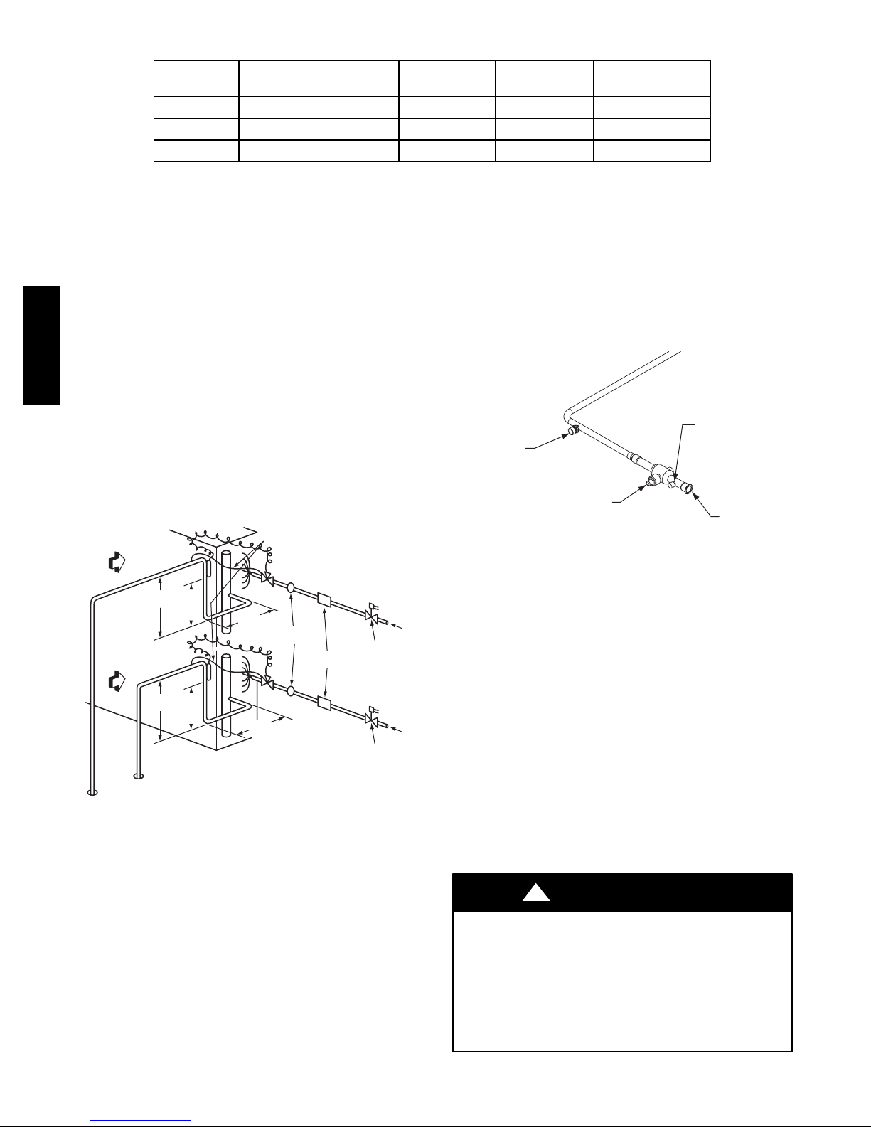
Table 7 – Refrigerant Specialties Part Numbers.
A
LIQUID LINE
SIZE (in.)
3
/
8
1
/
2
5
/
8
38AUD units require TWO sets of parts.
LIQUID LINE
SOLENOID VALVE (LLSV)
EF680033 EF680037 KM680008 KH43LG091
EF680035 EF680037 KM680004 KH43LG085
EF680036 EF680037 KM680005 KH43LG087
Select the filter driers for maximum unit capacity and
minimum pressure drop. Complete the refrigerant piping
from the indoor unit to the outdoor unit before opening
the liquid and suction lines at the outdoor unit.
INSTALL LIQUID LINE SOLENOID VALVE —
It is recommended that a solenoid valve be placed in the
main liquid line (see Fig. 8) between the condensing unit
and the evaporator coil. Locate the solenoid valve at the
outlet end of the liquid line, near the evaporator coil
38AUD
connections, with flow direction arrow pointed at the
evaporator coil. Refer to Table 7. (A liquid line solenoid
valve is required when the liquid line length exceeds 23 m
[75 ft].) This valve prevents refrigerant migration (which
causes oil dilution) to the compressor during the off cycle,
at low outdoor ambient temperatures. Wire the solenoid in
parallel with the compressor contactor coil (see Fig. 8).
This means of electrical control is referred to as solenoid
drop control.
8 DIAMS
MIN
8 DIAMS
EQUALIZER LINE
TXV
CKT 2
TXV
CKT 1
MIN
SIGHT
GLASSES
FILTER
DRIERS
AIRFLOW
AIRFLOW
SUCTION
CIRCUIT 2
TXV
SENSING
BULB
15 DIAMS
10
MIN
DIAMS
TXV
SENSING
BULB
15 DIAMS
10
MIN
DIAMS
SUCTION
CIRCUIT 1
Dual Circuit Coil Piping Configuration
For two circuit condensing units
Fig. 8 -- Location of Sight Glasses and Filter Driers
Typical 38AUD Systems
FLOW
LIQUID LINE
SOLENOID VALVE
CIRCUIT 2
FLOW
LIQUID LINE
SOLENOID VALVE
CIRCUIT 1
C10072
LLSV
COIL
The stub tube connections include
SIGHT
GLASS
FILTER
DRIER
1
/4-in SAE service
fittings with Schrader valve cores (see Fig. 9). Before
making any brazed connections to the unit service valves,
remove both Schrader valve caps and cores and save for
re-installation. Connect a source for nitrogen to one of
these service fittings during tube brazing to prevent the
formation of copper oxides inside the tubes at brazed
joints.
Field Service
Factory
High-Flow
ccess Port
Service Valve
with Stem Cap
Access Port
(Schrader core)
Sweat
Connection
Fig. 9 -- Typical Piping Connection Assembly
When connecting the field tubing to the 38AUD service
valves, wrap the valves in wet rags to prevent overheating
Pressure-test all joints from outdoor unit connections over
to the evaporator coil, using nitrogen as pressure and with
soap-and-bubbles.
When pressure-testing is completed, remove the nitrogen
source at the outdoor unit service valves and re-install the
two Schrader valve cores. Torque the cores to 23-34 N-cm
(2-3 in-lbs).
EVACUATION/DEHYDRATION — Evacuate and
dehydrate the connected refrigeration systems (excluding
the 38AUD unit) to 500 microns using a two-stage
vacuum pump attached to the service ports outside the
38AUD service valves, following description in GTAC II,
Module 4, System Dehydration.
C10073
CAPACITY CONTROL LIQUID LINE SOLENOID
VALVE Evaporator capacity control via liquid solenoid
valve is not recommended for use with 38AUD models.
MAKE PIPING CONNECTIONS — Piping connections
at the 38AUD unit are ball valves with stub tube
extensions. Do not open the unit service valves until all
interconnecting tube brazing as been completed.
!
WARNING
UNIT OPERATION AND SAFETY HAZARD
Failure to follow this warning could cause personal
injury, death and/or equipment damage.
R
Puron
(R--410A) refrigerant systems operate at
higher pressure than standard R--22 systems. Do not
use R--22 service equipment or components on Puron
refrigerant equipment.
12
Page 53
PRELIMINARY CHARGE — Before starting the unit,
charge R-410A liquid refrigerant into the high side of
each 38AUD circuit through the liquid service valve(s).
The amount of refrigerant added must be at least 80% of
the operating charge listed in Table 4 for LINEAR line
length LESS the factory charge quantity (if factory
shipping charge has not been removed). See example
below.
Allow high and low side pressures to equalize. If pressures
do not equalize readily, charge R-410A vapor (using
special service manifold with expansion device) into the
suction line service port for the low side of system to
assure charge in the evaporator. Refer to GTAC II,
Module 5, Charging, Recover, Recycling, and
Reclamation for liquid charging procedures.
Example:
38AUD*16
20 m linear line length
Equivalent line length 30 m
Liquid Lift: 10 m
(linear measure, indoor unit above outdoor unit)
Select line sizes from Table 4 (38AUD):
3
Liquid
Suction 1-1/8in.
Operating Charge
Each circuit: 7.0 kg (at 23 m linear length)
80% of Operating Charge:
Each circuit: 0.80 x 7.0 = 5.6 kg
Factory Shipping Charge: 2.7 kg
Field-charge quantity: 5.6 kg – 2.7 kg = 2.9 kg
For linear line lengths longer than 38 m (125 ft), contact
your local Carrier representative for system charge value.
/8in
Step 6 — Install Accessories
Accessories requiring modifications to unit wiring should
be completed now. These accessories may include Winter
Start controls, Low Ambient controls. Refer to the
instructions shipped with the accessory.
Step 7 — Complete Electrical Connections
!
WARNING
ELECTRICAL SHOCK HAZARD
Failure to follow this warning could result in personal
injury or death.
Do not use gas piping as an electrical ground. Unit
cabinet must have an uninterrupted, unbroken electrical
ground to minimize the possibility of personal injury if
an electrical fault should occur. This ground may
consist of electrical wire connected to unit ground lug
in control compartment, or conduit approved for
electrical ground when installed in accordance with
local electrical codes or in absence of local codes, it is
recommended that the U.S.A. standard ANSI/NFPA
70, National Electrical Code (NEC), be followed.
NOTE: Check all factory and field electrical connections
for tightness. Field-supplied wiring shall conform with the
limitations of 33°C(63°F) rise.
Field Power Supply —
All units are factory wired for the voltage shown on the
nameplate. Refer to unit label diagram for additional
information.
Field power wires are connected to the unit to compressor
contactor C1 and terminal block TB1 pressure lugs in the
unit’s main control box or at factory-installed option
non-fused disconnect switch (see Fig. 11). Max wire size
is #4 AWG (copper only).
NOTE: TEST LEADS -- Unit may be equipped with
short leads (pigtails) on the field line connection points on
contactor C or optional disconnect switch. These leads are
for factory run--test purposes only; remove and discard
before connecting field power wires to unit connection
points. Make field power connections directly to line
connection pressure lugs only.
38AUD
13
Page 54

!
WARNING
FIRE HAZARD
Failure to follow this warning could cause in personal
injury, death and/or equipment damage.
Do not connect aluminum wire between disconnect
switch and condensing unit. Use only copper wire.
(See Fig. 10.)
ELECTRIC
DISCONNECT
SWITCH
COPPER
WIRE ONLY
ALUMINUM
WIRE
Units Without Disconnect Option
C1 TB1
11 1 3
Disconnect
L1
L2 L3
Units With Disconnect Option
L1
L2
L3
2
4
6
Optional
Disconnect
Switch
1
3
5
Factory
Wiring
38AUD
A93033
Fig. 10 -- Disconnect Switch and Unit
Units Without Factory-Installed Disconnect —
When installing units, provide a disconnect switch of
adequate size per local or national wiring code.
Disconnect sizing data is provided on the unit informative
plate. Locate on unit cabinet or within sight of the unit per
national or local codes. Do not cover unit informative
plate if mounting the disconnect on the unit cabinet.
Units with Factory-Installed Disconnect —
The factory-installed option disconnect switch is located
in a weatherproof enclosure located under the main
control box. The manual switch handle is accessible
through an opening in the access panel.
All units All field wiring must comply with all local codes. Size
wire based on MCA (Minimum Circuit Amps) on the unit
informative plate. See Fig. 11 for power wiring
connections to the unit load terminals and equipment
ground.
Provide a ground--fault and short--circuit over--current
protection device (fuse or breaker) per local code (or in
absence of local code, is is recommended that U.S.A.
standard, NEC Article 440, be followed). Refer to unit
informative data plate for MOCP (Maximum
Over--current Protection) device size.
All field wiring must comply with the appropriate national
electrical codes and local requirements.
Disconnect factory test leads; discard.
C10074
Fig. 11 -- Power Wiring Connections
Affix the crankcase heater warning sticker to the unit
disconnect switch.
All Units —
Voltage to compressor terminals during operation must be
within voltage range indicated on unit nameplate. See
Table 8. On 3-phase units, voltages between phases must
be balanced within 2% and the current within 10%. Use
the formula shown in the legend for Table 8, Note 5 (see
page 16) to determine the percent of voltage imbalance.
Operation on improper line voltage or excessive phase
imbalance constitutes abuse and may cause damage to
electrical components. Such operation would invalidate
any applicable Carrier warranty.
Field Control Wiring — 38AUD unit control voltage is
24 v. See Fig. 18 and Fig. 19 for typical field control
connections and the unit’s label diagram for field-supplied
wiring details. Route control wires to the 38AUD unit
through the opening in unit’s end panel to the connections
terminal board in the unit’s control box.
Remainder of the system controls connection will vary
according to the specific construction details of the indoor
section (air handler or packaged fan coil). Fig. 12 depicts
typical connections to a Carrier 40RU fan coil unit. Plan
for field connections carefully and install control wiring
correctly per the project plan. Additional components and
supplemental transformer accessory may be required.
The 38AUD unit requires an external temperature control
device. This device can be a thermostat (field-supplied) or
a PremierLink controller (available as a field-installed
accessory, for use on a Carrier Comfort Network or as a
stand alone control).
14
Page 55
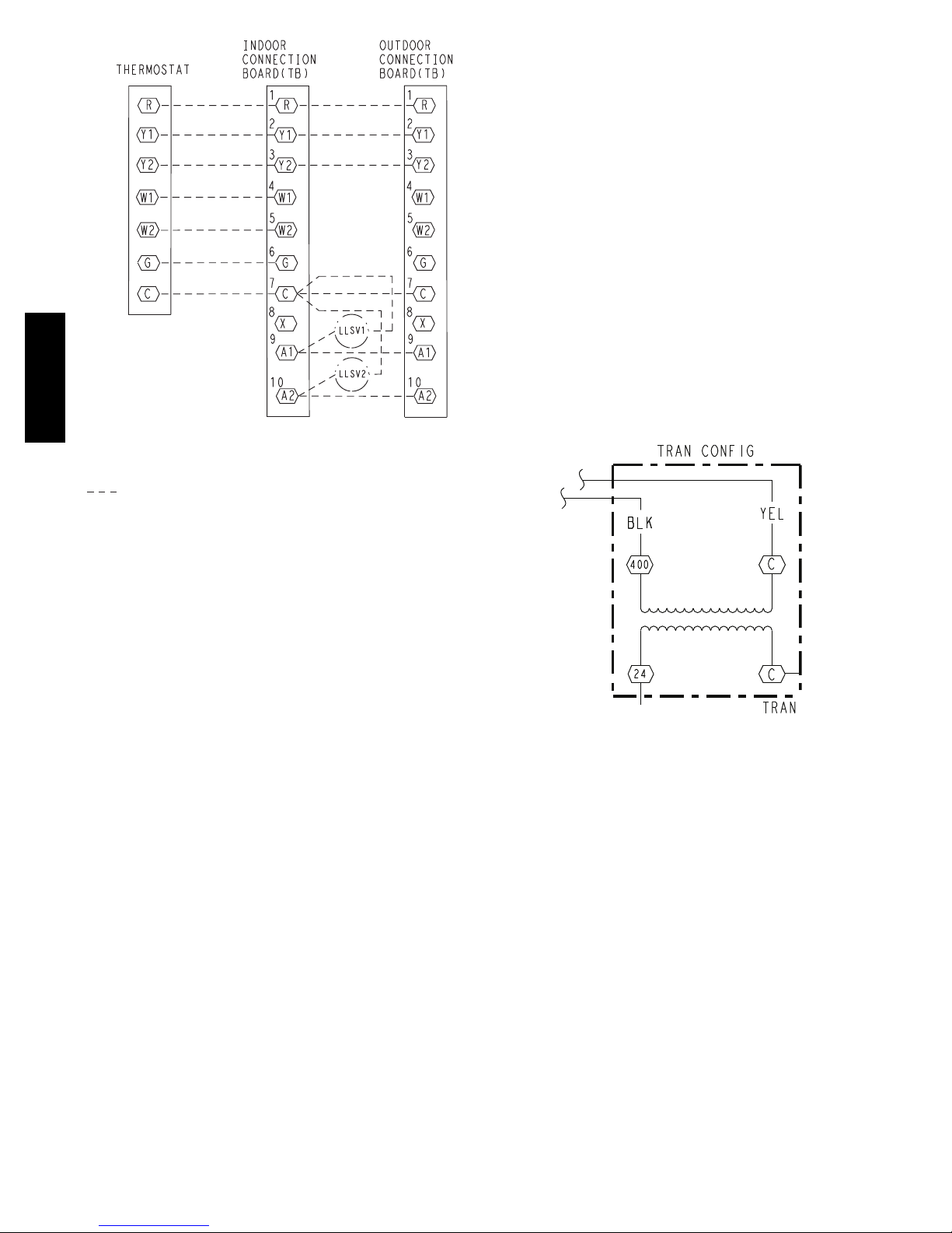
(Note 1)
(Note 3)
(Note 3)
(Note 2)
38AUD
Note 1: Typical multi-function marking. Follow manufacturer’s configuration
instructions to select Y2.
Note 2: Connect only if thermostat requires 24-vac power source.
Note 3: Connect W1 and W2 if supplemental heaters are installed
Field Wiring
Fig. 12 -- Typical Remote Thermostat Connections
For wire runs up to 15 m (50 ft.), use no. 18 AWG
(American Wire Gage) insulated wire (35°C minimum).
For15to23m(50to75ft.),useno.16AWGinsulated
wire (35°C minimum). For over 23 m (75 ft.), use no. 14
AWG insulated wire (35°C minimum). All wire sizes
larger than no. 18 AWG cannot be directly connected to
the thermostat and will require a junction box and splice
at the thermostat.
PremierLink (accessory installation) – Refer to Form
33CS-58SI for details on connecting the PremierLink
controller and its various sensors.
CONTROL CIRCUIT WIRING — Control voltage is
24 v. See Fig. 18 and Fig. 19 and the unit’s label diagram
for field--supplied wiring details. Route control wires
through the opening in unit’s end panel to the connection
in the unit’s control box.
CONTROL TRANSFORMER WIRING — On multi
voltage units, check the transformer primary wiring
connections. See Fig. 13 or refer to the unit’s label
diagram.
C10078
Thermostat —
Install a Carrier-approved accessory thermostat according
to installation instructions included with the accessory.
Locate the thermostat accessory on a solid wall in the
conditioned space to sense average temperature in
accordance with the thermostat installation instructions.
The 38AUD unit is a two-stage cooling unit. Select a
two-stage cooling thermostat.
Select a thermostat cable or equivalent single leads of
different colors with minimum of five leads for 38AUD
units. Check the thermostat installation instructions for
additional features which might require additional
conductors in the cable.
C10079
Fig. 13 -- Control Transformer Wiring
15
Page 56
Table 8 – Electrical Data — 38AUD*16--25 50 Hz Units
UNIT V-Ph -Hz
VOLTAGE
RANGE‡
COMPRESSOR 1 COMPRESSO R 2 OFM (ea)
MIN MAX RLA LRA RLA LRA WATTS FLA
38AUD*16 4 0 0 --- 3 --- 5 0 380 420 12.2 101 12.2 101 325 0.7 29.6 40
38AUD*25 4 0 0 --- 3 --- 5 0 380 420 16.7 111 16.7 111 325 0.7 40.4 50
Legend and Notes for Table 8
LEGEND:
F L A --- Fu l l L o a d A m p s
LRA --- Locked Rotor Amps
MCA -- - Minimum Circuit Amps
LRA --- Locked rotor amps
NEC --- National Electrical Code
RLA --- Rated Load Amps
‡
Units are suitable for use on electrical systems where voltage
supplied to the unit terminals is not below or above the listed
limits.
NOTES:
38AUD
1. In compliance with NEC requirements for multimotor and
combination load equipment (refer to NEC Articles 430 and
440), the overcurrent protective device for the unit shall be
fuse or HACR breaker.
2. TheMCAvaluesarecalculatedinaccordancewiththeNEC.
Article 440.
3. Motor RLA and LRA values are established in accordance
with Underwriters’ Laboratories (UL). Standard 1995.
4. Unbalanced 3-Phase Supply Voltage
Never operate a motor where a phase imbala nc e in supply
voltage is greater than 2%. Use the following formula to
determine the percentage of volt age imbalance.
Example: Supply voltage is 230-3-60
% Voltage Imbalance = 100 x
max voltage deviation from average voltage
average voltage
AB = 224 v
BC = 231 v
AC = 226 v
Average Voltage =
(224 + 231 + 226)
= 227
3
=
Determine maximum deviation from average voltage.
(AB) 227 – 224 = 3 v
(BC) 231 – 227 = 4 v
(AC) 227 – 226 = 1 v
Maximum deviation is 4 v.
Determine percent of voltage imbalance.
% Voltage Imbalance = 100 x
= 1.76%
4
227
This amount of phase imbalance is satisfactory as it is below the
maximum allowable 2%.
IMPORTANT: If the supply voltage phase imbalance is more than
2%, contact your local electric utility company immediately.
MCA
FUSE
SIZE
681
3
16
Page 57
PRE-START-UP
!
CAUTION
IMPORTANT: Before beginning Pre-Start-Up or
Start-Up, review Start-Up Checklist at the back of
this book. The Checklist assures proper start-up of a
unit and provides a record of unit condition,
application requirements, system information, and
operation at initial start-up.
!
CAUTION
UNIT DAMAGE HAZARD
Failure to follow this caution may result in equipment
damage.
Do not attempt to start the condensing unit, even
momentarily, until the following steps have been
completed. Compressor damage may result.
System Check
1. Check all air handler(s) and other equipment auxiliary
components. Consult the manufacturer’s instructions
regarding any other equipment connected to the condensing unit. If the unit has field-installed accessories, be sure all are properly installed and correctly
wired. If used, the airflow switch must be properly installed.
2. Be sure the unit is properly leak checked and dehydrated.
3. Check tightness of all electrical connections.
4. Open the liquid line and suction line service valves.
5. Be sure the unit is properly charged. See “Preliminary
Charge”, below.
6. The electrical power source must agree with the unit’s
nameplate rating.
7. The crankcase heater must be firmly attached to the
compressor crankcase. Be sure the crankcase is warm
(heater must be on for 24 hours before starting compressor).
Turn On Crankcase Heater — Turn on the crankcase
heater for 24 hours before starting the unit to be sure all
the refrigerant is out of the oil. To energize the crankcase
heater, proceed as follows:
1. Set the space thermostat set point above the space
temperature so there is no demand for cooling.
2. Close the field disconnect.
Preliminary Charge —Before starting the unit, charge
liquid refrigerant into the high side of the system through
the liquid service valve. The amount of refrigerant must
be at least 80% of the operating charge listed in the
Physical Data table (Tables 1A and 1B). Allow high and
low side pressures to equalize before starting compressor.
If pressures do not equalize readily, charge vapor on low
side of system to assure charge in the evaporator. Refer to
GTAC II, Module 5, Charging, Recover, Recycling, and
Reclamation for liquid charging procedures.
UNIT DAMAGE HAZARD
Failure to follow this caution may result in equipment
damage.
Prior to starting compressor, a preliminary charge of
refrigerant must be added to avoid possible
compressor damage.
START-UP
38AUD Units — The compressor crankcase heater must
be on for 24 hours before start-up. After the heater has
been on for 24 hours, the unit can be started. If no time
elapsed since the preliminary charge step was completed,
it is unnecessary to wait the 24-hour period.
PRELIMINARY CHECKS
1. Check that electric power supply agrees with unit
nameplate data.
2. Verify that the compressor crankcase heater is securely in place.
3. Check that the compressor crankcase heater has been
on at least 24 hours.
4. Recheck for leaks using the procedure outlined in the
Pre-Start-Up section, Leak Test and Dehydration. If
any leaks are detected, repair as required. Evacuate
and dehydrate as described in the Leak Test and Dehydration section.
5. Ensure that the preliminary charge has been added as
described in the Pre-Start-Up section, Preliminary
Charge.
6. All internal wiring connections must be tight, and all
barriers and covers must be in place.
NOTE: The 38AUD units are factory charged with the
required amount of oil. If recharging in required, use
Emkarate RL 32-3MAF for the 38AUD units.
COMPRESSOR ROTATION — On 3--phase units with
scroll compressors, it is important to be certain that the
compressor is rotating in the proper direction. 38AUD units
are equipped with a Comfort Alert Diagnostic Module
(CADM). Alert Code 7 indicates reverse power phasing.
To correct phase order:
1. Turn off power to the unit, tag disconnect.
2. Reverse any two of the unit power leads.
3. Reapply power to the compressor, verify correct pressures.
To verify the compressor is rotating in the proper direction:
1. Connect service gages to the suction and liquid pressure fittings.
2. Energize the compressor.
3. The suction pressure should drop and the liquid pressure should rise, as is normal on any start--up.
38AUD
17
Page 58
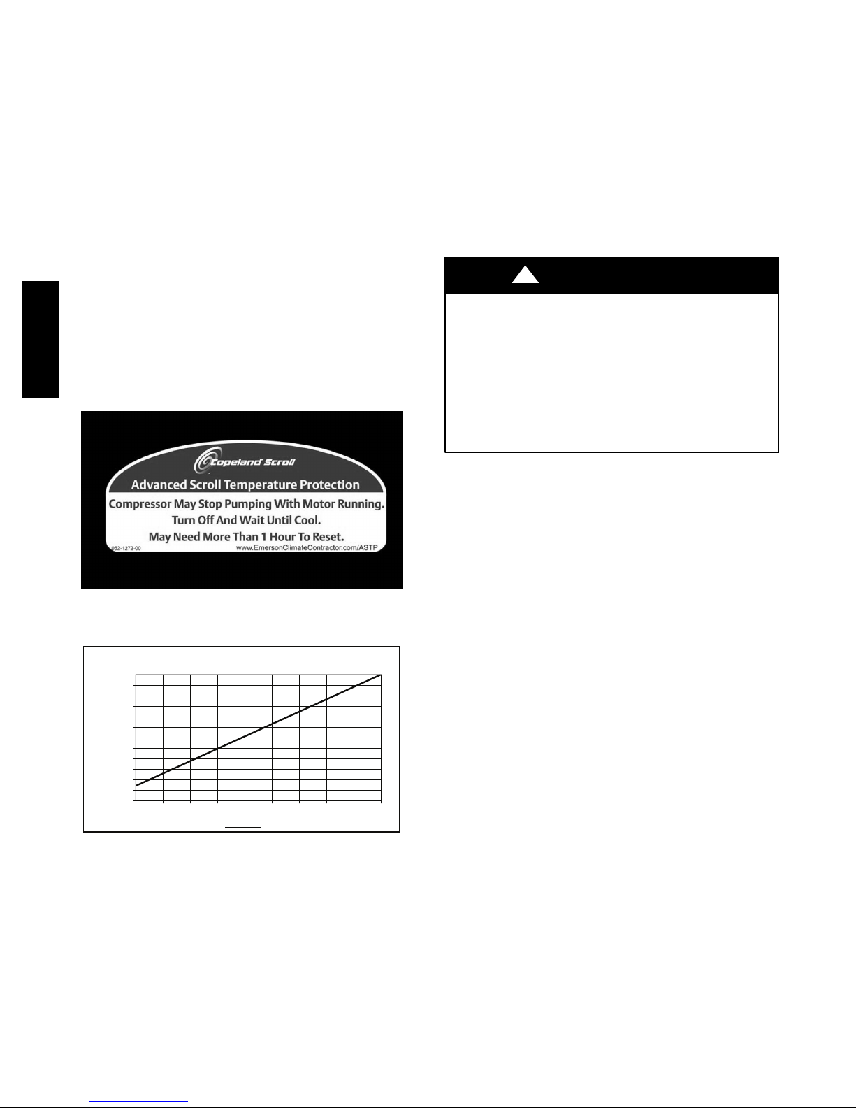
COMPRESSOR OVERLOAD — This overload interrupts
power to the compressor when either the current or
internal motor winding temperature becomes excessive,
and automatically resets when the internal temperature
drops to a safe level. This overload may require up to 60
minutes (or longer) to reset. If the internal overload is
suspected of being open, disconnect the electrical power
to the unit and check the circuit through the overload with
an ohmmeter or continuity tester.
ADVANCED SCROLL TEMPERATURE PROTECTION
(ASTP) — A label located above the terminal box identifies
Copeland Scroll compressor models that contain this
technology. See Fig. 14. Advanced Scroll Temperature
Protection (ASTP) is a form of internal discharge
temperature protection, that unloads the scroll compressor
when the internal temperature reaches approximately 149_C
(300_F). At this temperature, an internal bi--metal disk valve
opens and causes the scroll elements to separate, which
stops compression. Suction and discharge pressures balance
38AUD
while the motor continues to run. The longer the compressor
runs unloaded, the longer it must cool before the bi--metal
disk resets. See Fig. 15.
To manually reset ASTP, the compressor should be
stopped and allowed to cool. If the compressor is not
stopped, the motor will run until the motor protector trips,
which occurs up to 90 minutes later. Advanced Scroll
Temperature Protection will reset automatically before the
motor protector resets, which may take up to 2 hours.
START UNIT — Set the space thermostat to a set point
above space temperature so that there is no demand for
cooling. Close the 38AUD disconnect switch. Only the
crankcase heater will be energized.
Reset the space thermostat below ambient so that a call
for cooling is ensured.
!
CAUTION
UNIT DAMAGE HAZARD
Failure to follow this caution may result in equipment
damage.
Never charge liquid into the low-pressure side of
system. Do not overcharge. During charging or
removal of refrigerant, be sure indoor-fan system is
operating. Ensure both outdoor fan motors are
running; bypass any Motormaster function.
C10080
Fig. 14 -- Advanced Scroll Temperature Protection Label
120
110
100
90
80
70
60
50
(Minutes)
40
30
20
Recommended Cooling Time*
10
0
0 10203040 607080 9050
*Times are approximate.
NOTE: Various factors, including high humidity, high ambient
temperature, and the presence of a sound blanket will
increase cool-down times.
Compressor Unloaded Run Time (Minutes)*
C10081
Fig. 15 -- Recommended Minimum Cool-Down Time
After Compressor is Stopped
ADJUST REFRIGERANT CHARGE — Refer to Cooling
Charging Charts, Fig. 16 and Fig. 17. For applications
with line lengths greater than 38m (125 ft), contact Carrier
representative. Vary refrigerant until the conditions of the
chart are met. Note that the charging charts are different
from the type normally used. The charts are based on
charging the units to the correct subcooling for the various
operating conditions. Accurate pressure gage and
temperature sensing device are required. Connect the
pressure gage to the service port on the liquid line service
valve. Mount the temperature sensing device on the liquid
line close to the liquid line service valve, and insulate it so
that outdoor ambient temperature does not affect the
reading. Indoor airflow must be within the unit’s normal
operating range. Operate the unit for a minimum of 15
minutes. Ensure that pressure and temperature readings
have stabilized. Plot the liquid pressure and temperature
on chart and add or reduce the charge to meet the curve.
Adjust the charge to conform with the charging chart,
using the liquid pressure and temperature to read the
chart.
FINAL CHECKS — Ensure that all safety controls are
operating, control panel covers are on, and the service
panels are in place.
18
Page 59
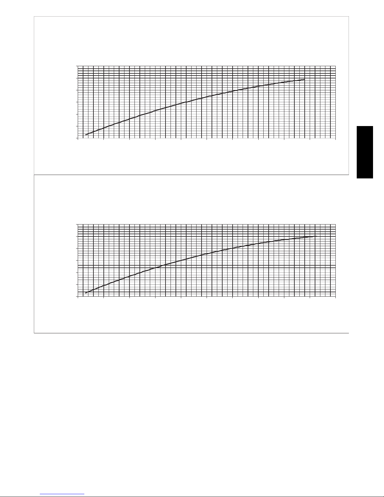
38AUD-16 Charging Chart Puron
Circuit 1
All Condenser Fans Operating
150.00
130.00
110.00
90.00
70.00
50.00
Temperature at Liquid Valve (°F)
30.00
140.00 190.00 240.00 290.00 340.00 390.00 440.00 490.00 540.00 590.00 640.00
Pressure at Liquid Valve (psig)
38AUD
38AUD-16 Charging Chart Puron
Circuit 2
All Condenser Fans Operating
Temperature at Liquid Valve (°F)
150.00
130.00
110.00
90.00
70.00
50.00
30.00
140.00 190.00 240.00 290.00 340.00 390.00 440.00 490.00 540.00 590.00 640.00
Pressure at Liquid Valve (psig)
C10082
Fig. 16 -- 38AUD*16 Charging Chart
19
Page 60

38AUD-25 Charging Chart Puron
Circuit 1
4 Condenser Fans Operating
120.00
110.00
100.00
90.00
80.00
70.00
60.00
50.00
40.00
30.00
Temperature at Liquid Valve (°F)
140.00 190.00 240.00 290.00 340.00 390.00 440.00 490.00
Pressure at Liquid Valve (psig)
38AUD
38AUD-25 Charging Chart Puron
Circuit 2
4 Condenser Fans Operating
120.00
110.00
100.00
90.00
80.00
70.00
60.00
50.00
40.00
Temperature at Liquid Valve (°F)
30.00
140.00 190.00 240.00 290.00 340.00 390.00 440.00 490.00
Pressure at Liquid Valve (psig)
Fig. 17 -- 38AUD*25 Charging Chart
C10083
20
Page 61
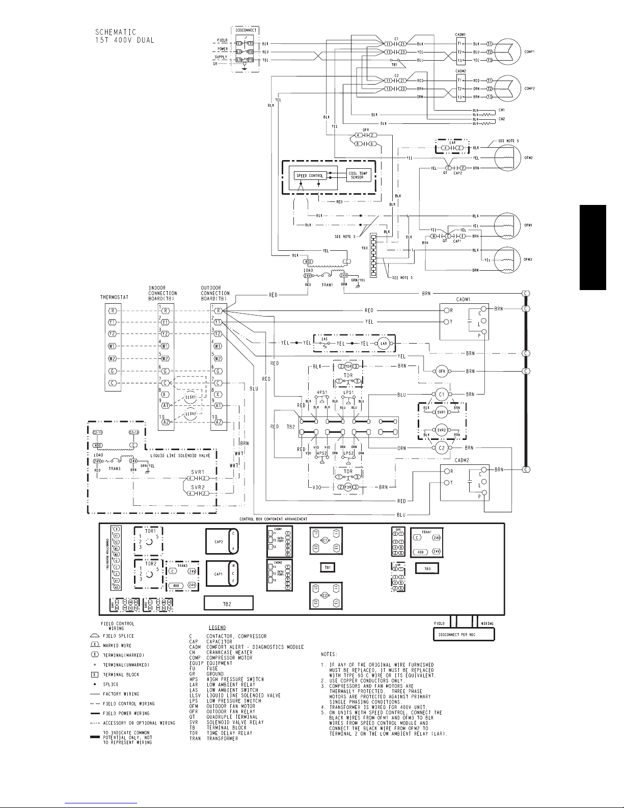
38AUD
C10084
Fig. 18 -- Typical 38AUD*16 Wiring Diagram
21
Page 62
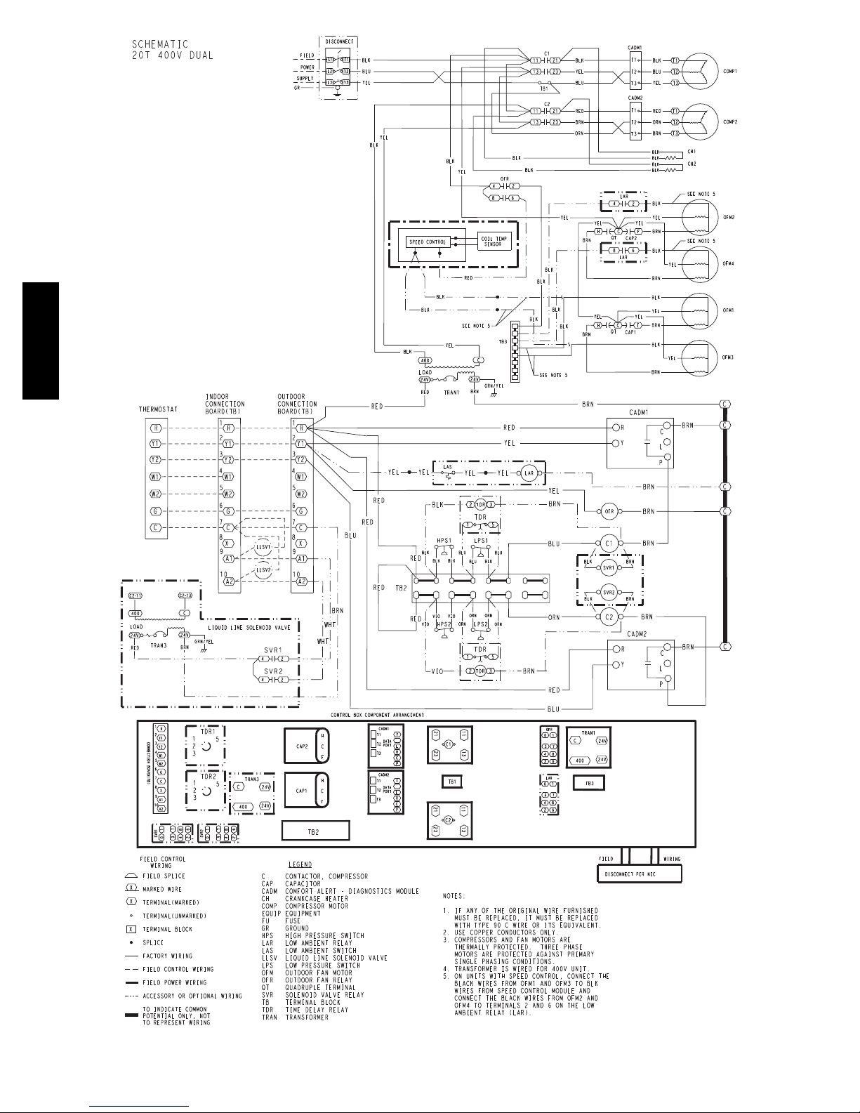
38AUD
C10085
Fig. 19 -- Typical 38AUD*25 Wiring Diagram
22
Page 63
OPERATING SEQUENCE
Base Unit Controls
Indoor (Supply) Fan
The indoor fan contactor (IFC) is remotely located at the fan
coil or fan section. If the thermostat fan operation is selected
as Continuous, the IFC is energized and the indoor (supply)
fan motor runs continuously. If the thermostat fan operation
is selected as Automatic, the IFC will be energized on a call
for Cooling; indoor (supply) fan motor runs. When
thermostat call for Cooling is satisfied, the IFC is
de-energized and indoor (supply) fan motor stops.
Cooling, Unit Without Economizer
38AUD
On a thermostat call for Cooling, IFC will be energized
and indoor (supply) fan motor runs. Thermostat output Y1
is energized; terminal Y1 at 38AUD unit receives 24-v.
24-v received at CADM1 terminal Y. If anti-recycle time
delay period has not expired, CADM1 relay will remain
open, de-energizing Solenoid Valve Relay 1 (SVR1) and
preventing compressor start. When safety pressure
switches are closed and CADM1 time delay expires,
CADM1 relay closes, SVR1 and compressor contactor C1
are energized; liquid line solenoid valve LLSV1 opens, all
outdoor fan motors start and Circuit 1 compressor starts.
As space cooling load is satisfied, thermostat outputs Y2
and Y1 are de--energized, removing 24-v at 38AUD
terminals Y2 and Y1. Circuit 2 compressor stops on Y2
opening; SVR2 is de-energized and LLSV2 closes.
CADM2 begins its three-minute anti-recycle time delay.
On Y1 opening, Circuit 1 compressor stops, all outdoor
fan motors stop and SVR1 relay is de-energized. Liquid
line solenoid valve LLSV1 is de-energized and valve
closes. CADM1 begins its three-minute anti-recycle time
delay.
If either the Low Pressure Switch or High Pressure Switch
opens while thermostat output Y1 or Y2 remain energized,
the compressor contactor is de-energized, the compressor
stops and liquid line solenoid is de-energized (valve
closes). CADM initiates a TRIP event (cooling demand
sensed at CADM terminal Y but no current is measured at
T1, T2, T3 motor sensors); CADM relay opens and RED
LED is illuminated. TRIP condition maintains lockout of
compressor operation until CADM is manually reset.
Reset CADM by cycling unit main power.
Complete system shutdown may be caused by loss of
main power, open compressor internal overload, open
low-pressure or high-pressure switch, or a fault detected
by the CADM logic. Compressor operation without
cooling may indicate the compressor’s ASTP feature is
active; disconnect unit power and allow compressor to
cool. See Service section for further details.
38AUD
On a thermostat calling for Stage 2 Cooling, thermostat
output Y2 is energized; terminal Y2 at 38AUD unit
receives 24-v. 24-v received at CADM2 terminal Y. If
anti-recycle time delay period has not expired, CADM2
relay will remain open, de-energizing Solenoid Valve
Relay 2 (SVR2) and preventing compressor start. When
safety pressure switches are closed and CADM2 time
delay expires, CADM2 relay closes, SVR2 and
compressor contactor C2 are energized; liquid line
solenoid valve LLSV2 opens and Circuit 2 compressor
starts.
Cooling, Unit With Economizer
Refer to fan coil unit installation instructions and
economizer accessory installation instructions for operating
sequences when system is equipped with accessory
economizer.
Heating
Refer to fan coil unit installation instructions and
accessory heating device installation instructions for
operating sequences in heating mode.
23
Page 64

ROUTINE SYSTEM MAINTENANCE
SERVICE
These items should be part of a routine maintenance
program, to be checked every month or two, until a
specific schedule for each can be identified for this
installation:
Quarterly Inspection
and 30 days after initial start)
Indoor section
S Condenser coil cleanliness checked.
S Return air filter replacement
S Outdoor hood inlet filters cleaned
S Belt tension checked
S Belt condition checked
S Pulley alignment checked
S Fan shaft bearing locking collar tightness checked
38AUD
S Condensate drain checked
Seasonal Maintenance
These items should be checked at the beginning of each
season (or more often if local conditions and usage
patterns dictate):
Air Conditioning
S Condenser fan motor mounting bolts tightness
S Compressor mounting bolts
S Condenser fan blade positioning
S Control box cleanliness and wiring condition
S Wire terminal tightness
S Refrigerant charge level
S Evaporator coil cleaning
S Evaporator blower motor amperage
Heating
S Power wire connections
S Fuses ready
S Manual-reset limit switch is closed
Economizer or Outside Air Damper
Inlet filters condition
Check damper travel (economizer)
Check gear and dampers for debris and dirt
Refrigeration System
!
EQUIPMENT DAMAGE HAZARD
Failure to follow this caution may result in damage to
equipment.
This system uses Puron
pressures than R-22 and other refrigerants. No other
refrigerant may be used in this system. Gage set,
hoses, and recovery system must be designed to
handle Puron. If you are unsure consult the equipment
manufacturer.
CAUTION
R
refrigerant which has higher
Compressor Oil —
!
EQUIPMENT DAMAGE HAZARD
Failure to follow this caution may result in damage to
equipment.
The compressor in a Puron system uses a polyolester
(POE) oil. This oil is extremely hygroscopic, meaning
it absorbs water readily. POE oils can absorb 15 times
as much water as other oils designed for HCFC and
CFC refrigerants. Take all necessary precautions to
avoid exposure of the oil to the atmosphere.
Servicing Systems on Roofs With Synthetic Materials —
POE (polyolester) compressor lubricants are known to cause
long term damage to some synthetic roofing materials.
Exposure, even if immediately cleaned up, may cause
embrittlement (leading to cracking) to occur in one year or
more. When performing any service which may risk
exposure of compressor oil to the roof, take appropriate
precautions to protect roofing. Procedures which risk oil
leakage include but are not limited to compressor
replacement, repairing refrigerants leaks, replacing
refrigerant components such as filter drier, pressure switch,
metering device, coil, accumulator, or reversing valve.
SYNTHETIC ROOF PRECAUTIONARY
PROCEDURE
1. Cover extended roof working area with an impermeable polyethylene (plastic) drop cloth or tarp.
Cover an approximate 3.3 x 3.3 m (10 x 10 ft) area.
2. Cover area in front of the unit service panel with a
terry cloth shop towel to absorb lubricant spills and
prevent run-offs, and protect drop cloth from tears
caused by tools or components.
3. Place terry cloth shop towel inside unit immediately under component(s) to be serviced and prevent lubricant
run-offs through the louvered openings in the base pan.
4. Perform required service.
5. Remove and dispose of any oil contaminated material
per local codes.
CAUTION
24
Page 65

Liquid Line Filter Drier — The factory-provided filter
drier is specifically designed to operate with Puron®.
Replace the filter drier with factory-authorized components
only with a filter drier with desiccant made from 100%
molecular sieve grade XH-11. Filter drier must be replaced
whenever the refrigerant system is opened.
When removing a filter drier, use a tubing cutter to cut the
drier from the system. Do not unsweat a filter drier from
the system. Heat from unsweating will release moisture
and contaminants from drier into system.
Field Refrigerant Access Ports — Field service access to
refrigerant pressures is through the access ports located at
the service valves (see Figs 26 and 28). These ports are
1
/4-in SAE Flare couplings with Schrader check valves
and service caps. Use these ports to admit nitrogen to the
field tubing during brazing, to evacuate the tubing and
evaporator coil, to admit initial refrigerant charge into the
low-side of the system and when checking and adjusting
the system refrigerant charge. When service activities are
completed, ensure the service caps are in place and
secure; check for leaks. If the Schrader check valve must
be removed and re-installed, tighten to 23-34 N-cm (2-3
in-lbs).
Factory High-Flow Access Ports — There are two
additional access ports in the system - on the suction tube
between the compressor and the suction service valve and
on the liquid tube near the liquid service valve (see Fig.
23 and Fig. 25). These are brass fittings with black plastic
caps. The hose connection fittings are standard
1
/4-in SAE
Male Flare couplings.
The brass fittings are two-piece High Flow valves, with a
receptacle base brazed to the tubing and an integral
spring-closed check valve core screwed into the base. (See
Fig. 20.) This check valve is permanently assembled into
this core body and cannot be serviced separately; replace
the entire core body if necessary. Service tools are
available from RCD that allow the replacement of the
check valve core without having to recover the entire
system refrigerant charge. Apply compressor refrigerant
oil to the check valve core’s bottom o-ring. Install the
fitting body with 1085 ±23 N-cm (96 ±-10 in-lbs) of
torque; do not overtighten.
Comfort Alert Diagnostic Module
The Comfort Alert Diagnostic Module (CADM) monitors
and analyzes data from the Copeland Scroll
compressor and the thermostat demand. The CADM also
®
three-phase
provides a 3-minute anti-recycle time delay to compressor
cycling.
The CADM detects causes for electrical and system
related failures without any sensors. Flashing LEDs
communicate the Alert codes to guide service technicians
in accurately and quickly troubleshooting the system and
determining root cause for the failure.
Inputs to the CADM include 24-vac power, thermostat
Y1, compressor contactor coil (common side) and
compressor power leads (from the compressor contactor).
Input Te r m i n a l Voltage
Control
Power
Control
Common
Cooling Y 24-V
Contactor
Coil
Line A T1 Line
Line B T2 Line
Line C T3 Line
R 24-V
C 24-V
P 24-V
Control of the compressor contactor coil is through a
normally-closed (power on the module) contact between
terminals P and C.
Communications of status and alert conditions is through
three LEDs located on the top edge of the module housing
(see Fig. 21): POWER (green), ALERT (yellow), and
TRIP (red).
The POWER LED indicates the presence of control power
to the CADM.
The ALERT LED indicates an abnormal condition exists
in the system through a flash code. The ALERT LED will
blink a number of times consecutively, pause and the
repeat the process. The number of blinks, defined in Table
9, correlates to a particular abnormal condition;
troubleshooting tips are provided for each Alert code.
Reset of the ALERT may be automatic or manual. If the
fault condition causing the Alert is self-corrected, the
Alert code will be removed and the CADM will
automatically reset and allow the system to restart
normally. Manual reset requires that main power to the
38AUD unit be recycled after the cause for the Alert
condition has been detected and corrected.
38AUD
SEAT
5/8” HEX
.47
CORE
(Part No. EC39EZ067)
1/2-20 UNF RH
0.596
30°
WASHER
O-RING
This surface provides a metal to metal seal when
torqued into the seat. Appropriate handling is
required to not scratch or dent the surface.
1/2" HEX
Fig. 20 -- CoreMax Access Port Assembly
25
45°
DEPRESSOR PER ARI 720
+.01/-.035
FROM FACE OF BODY
7/16-20 UNF RH
C08453
Page 66
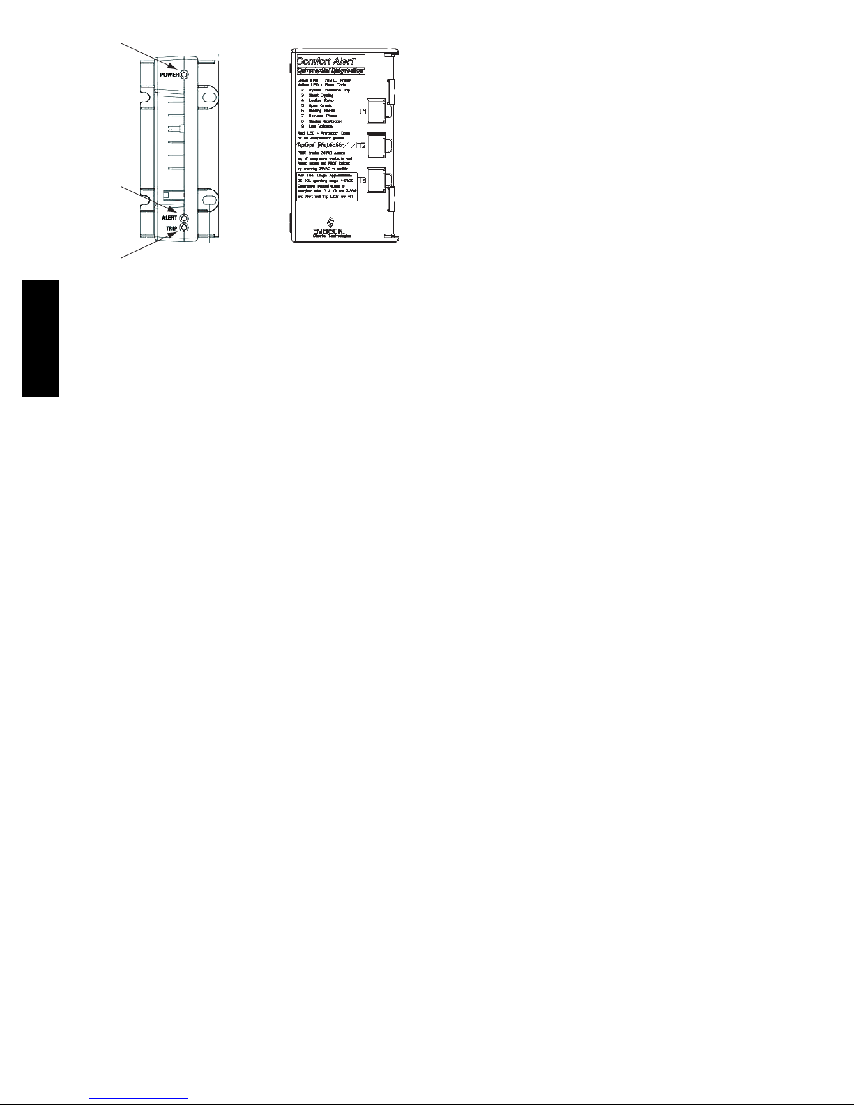
POWER
(GRN)
The TRIP LED indicates either a time-delay period is
currently active (RED LED is blinking) or the module has
locked out the compressor (RED LED is on steady). A
lockout condition will occur when the CADM detects a
thermostat demand at input Y but there is no power at the
compressor line terminals T1 or T2 or T3. This lockout
can occur due to a safety switch (LPS or HPS) opening
and de-energizing the compressor contactor, the
compressor-motor internal overload opens, or other
ALERT
(YEL)
internal power interruption has occurred. Reset of the
TRIP LED requires that unit main power be recycled after
the loss of power to the compressor condition has been
detected and corrected.
TRIP
(RED)
Fig. 21 -- CADM Housing/LED Locations
C10086
Simultaneous Blinking of YELLOW and RED LEDs
indicates control power input to the CADM is low. Check
control circuit transformer and wiring.
Troubleshooting the CADM Wiring – Flashing LEDs also
indicate wiring problems to the CADM. See Table 10 for
38AUD
discussion of additional LED flash codes and
troubleshooting instructions.
26
Page 67
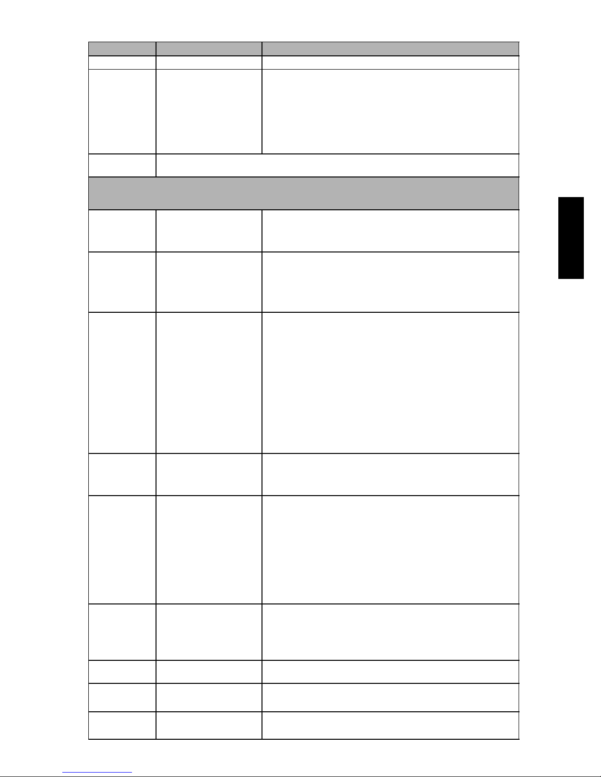
Table 9 – LED Status Codes
Status LED Status LED Description Status LED Troubleshooting Information
Green “POWER” Module has power Supply voltage is present at module terminals
Red “TRIP”
LED On Solid
Red “TRIP” LED
Flashing
Module locks out compressor when compressor damaging ALERT code appears.
Lockout ALERT codes are noted in the Status LED Description.
During a compressor lock out, 24VAC power must be removed from module to manually reset.
Yellow “ALERT”
LED On Solid
Yellow “ALERT”
Flash Code 2
Yellow “ALERT”
Flash Code 3
Yellow “ALERT”
Flash Code 4
Yellow “ALERT”
Flash Code 5
Yellow “ALERT”
Flash Code 6
Yellow “ALERT”
Flash Code 7
Yellow “ALERT”
Flash Code 8
Yellow “ALERT”
Flash Code 9
Thermostat demand signal
Y is present, b ut the compressor is not running.
The anti-short cycle timer (3 minutes), in module is preventing compressor restart.
A short circuit or over current condition exists on
PROT terminal.
System Pressure Trip Discharge pressure out of limitsorcompressoroverload
(if no high pressure switch
in system)
LOCKOUT
Short Cycling
Compressor is running only
briefly LOCKOUT
Locked Rotor
LOCKOUT
Open Circuit
Missing Phase
LOCKOUT
Reverse Phase
LOCKOUT
Welded Contactor Compressor always runs
Low Voltage
Control circuit < 18VAC
1. Compressor protector is open
2. Condensing unit power disconnect is open
3. Compressorcircuitbreakerorfuse(s)isopen
4. Broken supply wires or connector is not making contact
5. Compressor power wires not routed through Comfort Alert
6. Compressor contactor has failed open
1. Compressor contactor coil shorted
2. Electrical load too high for PROT circuit (maximum 1 Amp)
3. 24 V AC wired directly to PROT terminal
1. High head pressure
2. Condenser coil poor air circulation (dirty, blocked, damaged)
3. Condenser fan is not running
4. If low pressure switch is open: Refer to Code 3 for troubleshooting
1. If low pressure switch is open:
a. Low refrigerant charge
b. Evaporator blower is not running
c. Evaporator coil is frozen
d. Faulty metering device
e. Condenser coil is dirty
f. Liquid line restriction (filter drier blocked if present)
2. If high pressure switch is open, go to Flash Code 2 information
3. Intermittent thermostat demand signal
4. System or control board defective
1. Low line voltage to compressor
2. Excessive liquid refrigerant in compressor
3. Compressor bearings are seized
1. Condensing unit power disconnect is open
2. Compressorcircuitbreakerorfusesareopen
3. Compressor contactor has failed open
4. High pressure switch is open and requires manual reset
5. Broken supply wires or connector is not making contact
6. Unusually long compressor protector reset time d ue to extreme
ambient temperature
7. Compressor windings are damaged
1. Compressorfuseisopenononephase
2. Broken wire or connector on one phase
3. Compressor motor winding is damaged
4. Utility supply has dropped one phase
1. Compressor running backward due to supply phase reversal
1. Compressor contactor has failed closed
2. Thermostat demand signal not connected to module
1. Control circuit transformer is overloaded
2. Low line voltage to compressor
38AUD
27
Page 68
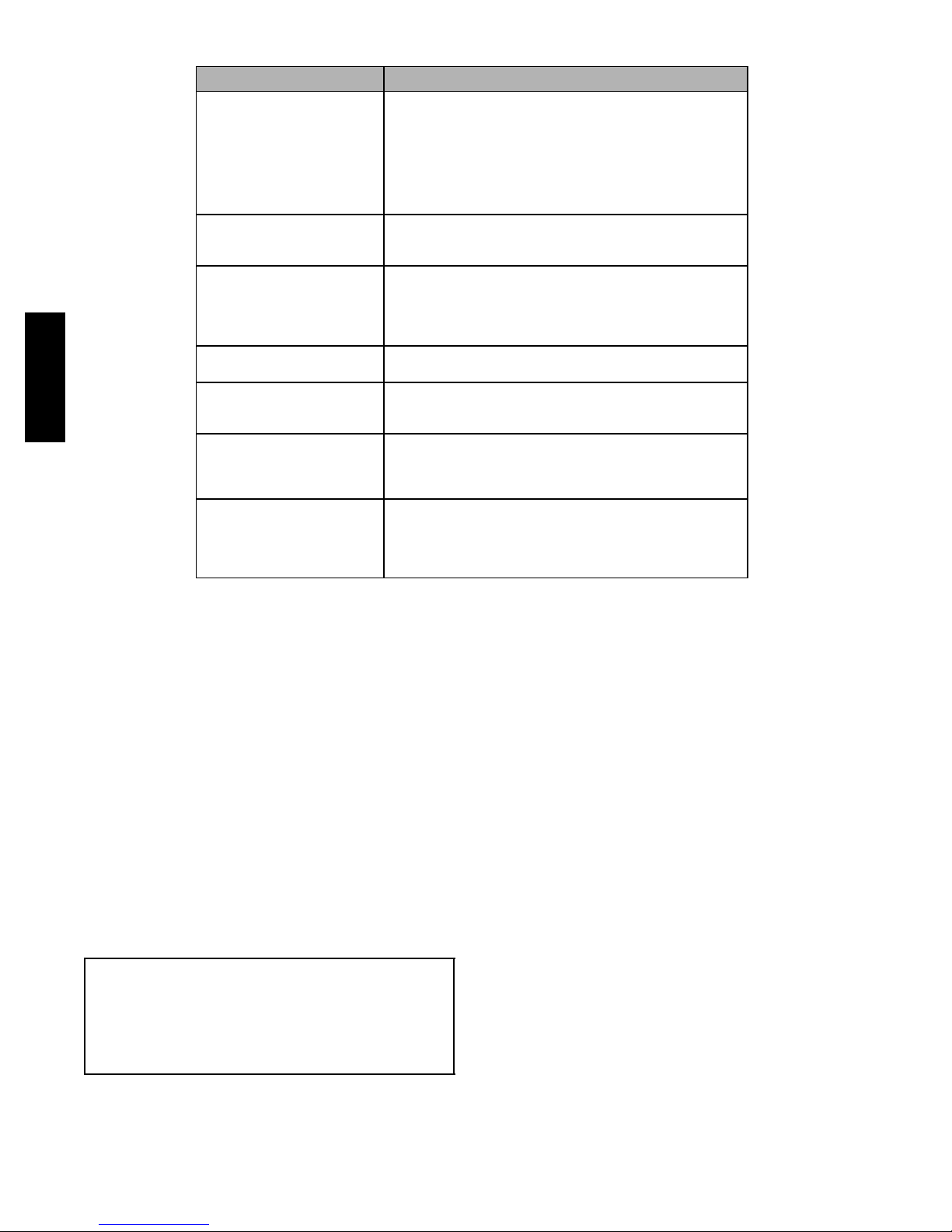
Table 10 – CADM Troubleshooting
Miswired Module Indication Recommended Troubleshooting Action
Green LED is not on,
module does not power up
Green LED Intermittent,
module powers up only
when compressor runs
TRIP LED is on but system
and compressor check OK
TRIP LED and ALERT LED
flashing together
38AUD
ALERT Flash Code 3
(Compressor Short Cycling)
displayed incorrectly
ALERT Flash Code 5 or 6
(Open Circuit, Missing Phase)
displayed incorrectly
Alert Flash Code *
(Welded Contactor)
displayed incorrectly
Determine if both R and C module terminals are connected.
Verify voltage in present at module’s R and C terminals.
NOTE: The CADM requires a constant nominal 24VAC power
supply. The wiring to the module’s R and C terminals must be
directly from the control transformer. The module cannot receive its power from another device that will interrupt the 24VAC
power supply. See the 38AUD Wiring Diagrams (Fig. 18 and
Fig. 19).
Determine if R and Y terminals are wired in reverse. Verify module’s R and C terminals have a constant source. See “NOTE”
above for details on R and C wiring.
Verify Y terminal is wired properly per the 38AUD wiring diagram (see Fig. 18 and Fig. 19). Verify voltage at contactor coil
falls below 0.5VAC when off. Verify 24VAQC is present across Y
and C when thermostat demand signal is present. If not, R and
C a re reverse wired.
Verify R and C terminals are supplied with 19-28VAC.
Verify Y terminal is connected to 24VAC at contactor coil. Verify
voltage at contactor coil falls below 0.5VAC when off.
Check that compressor T1 and T3 wires are through module’s
current sensing holes. Verify Y terminal is connected to 24VAC
at contactor coil. Verify voltage at contactor coil falls below
0.5VAC when off.
Determine if module’s Y terminal is connected. Verify Y terminal
is connected to 24VAC at contactor coil. Verify 24VAC is present
across Y and C when thermostat demand signal is present. If
not, R and C are reverse wired. Verify voltage at contactor coil
falls below 0.5VAC when off.
Crankcase Heater — The heater prevents refrigerant
migration and compressor oil dilution during shutdown
whenever compressor is not operating. The heater is wired
to cycle with the compressor; the heater is off when
compressor is running, and on when compressor is off.
The crankcase heater will operate as long as the power
circuit is energized.
Compressor Protection
COMPRESSOR OVERTEMPERATURE PROTECTION
(IP) — A thermostat installed on the compressor motor
winding reacts to excessively high winding temperatures
and shuts off the compressor.
CRANKCASE HEATER — The heater minimizes
absorption of liquid refrigerant by oil in the crankcase
during brief or extended shutdown periods. The main
disconnect must be on to energize the crankcase heater.
IMPORTANT: Never open any switch or disconnect
that energizes the crankcase heater unless unit is
being serviced or is to be shut down for a prolonged
period. After a prolonged shutdown on a service job,
energize the crankcase heater for 24 hours before
starting the compressor.
ADVANCED SCROLL TEMPERATURE PROTECTION
(ASTP) — See “Advanced Scroll Temperature Protection
(ASTP)” on page 18.
Low-Pressure Switch — The low-pressure switch is
stem-mounted on the suction line. Switches are all fixed,
non-adjustable type.
High--Pressure Switch — The high--pressure switch is
stem mounted on the discharge line. The switch is a fixed,
non-adjustable type.
Outdoor Fans — Each fan is supported by a formed-wire
mount bolted to the fan deck and covered with a wire
guard. Fan motors have permanently lubricated bearings.
Lubrication
FAN MOTORS have sealed bearings. No provisions are
made for lubrication.
COMPRESSOR has its own oil supply. Loss of oil due to
a leak in the system should be the only reason for adding
oil after the system has been in operation.
28
Page 69
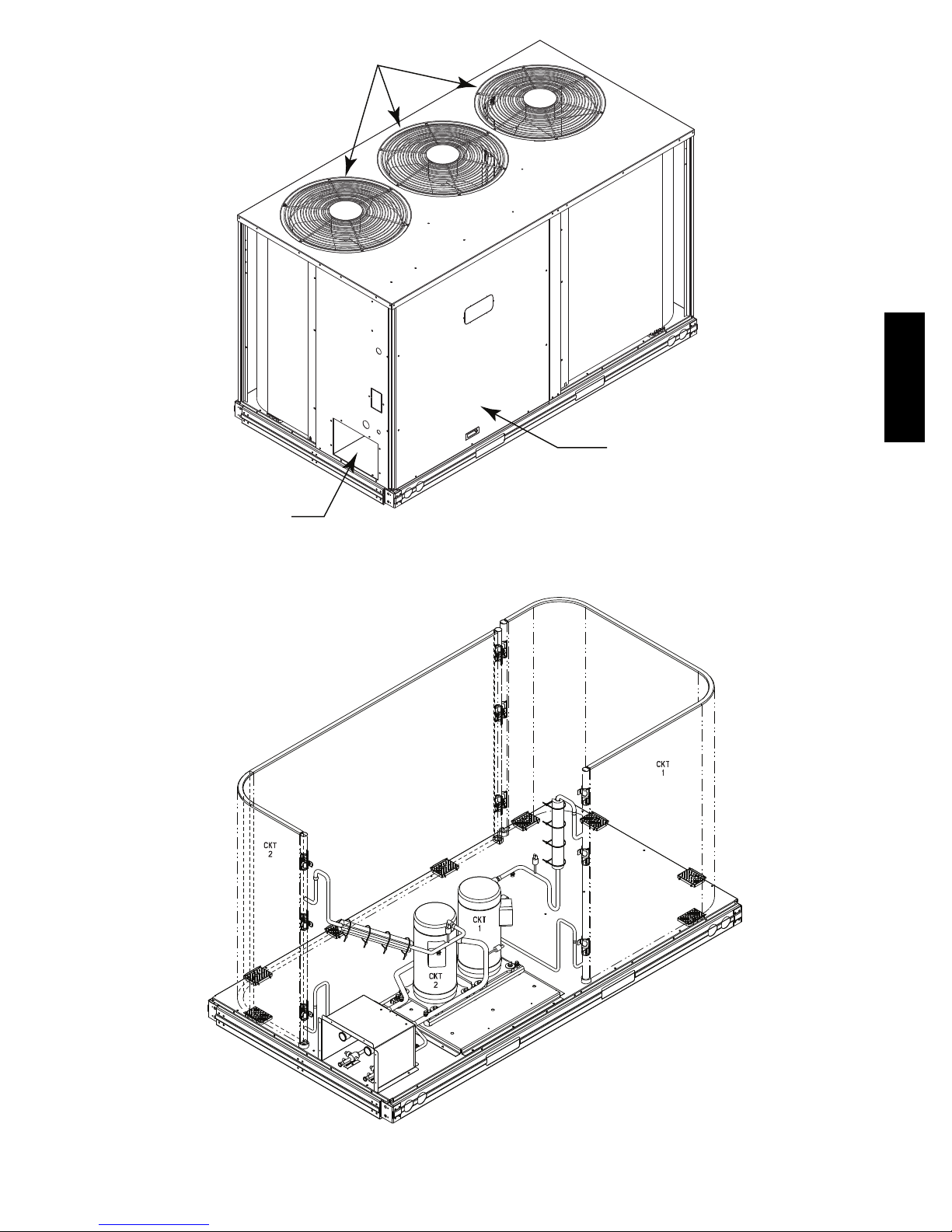
Condenser Fans/Motors
38AUD
Access Panel Control Box &
Compressors
Service
Valves
C10087
Fig. 22 -- 38AUD Size 16 Cabinet
C10095
Fig. 23 -- 38AUD*16 Piping
29
Page 70
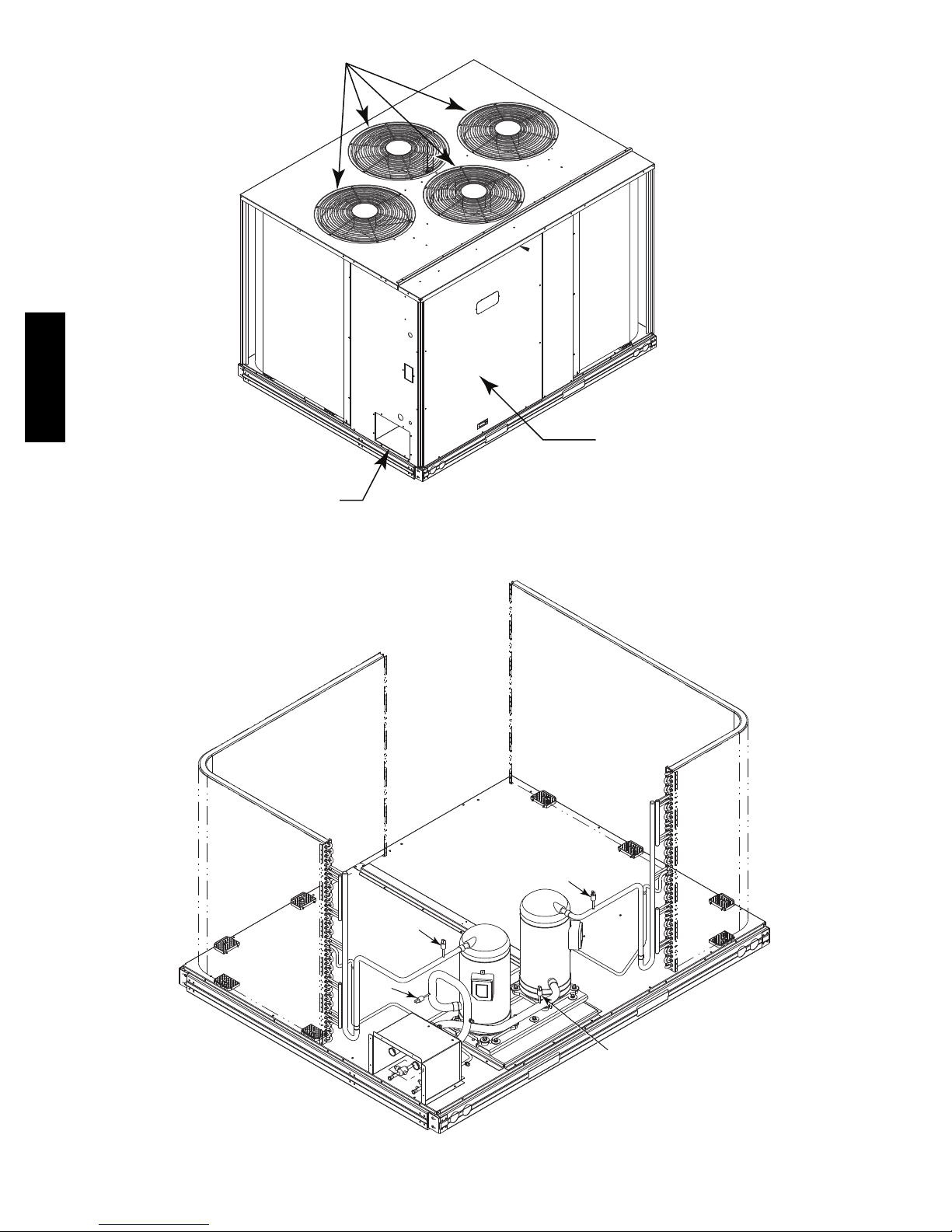
Condenser Fans/Motors
38AUD
Access Panel Control Box &
Compressors
Service
Valves
C10089
Fig. 24 -- 38AUD Size 25 Cabinet
CKT
2
HPS
LPS
CKT
2
Fig. 25 -- 38AUD*25 Piping
30
CKT
CKT
1
HPS
1
LPS
C10090
Page 71
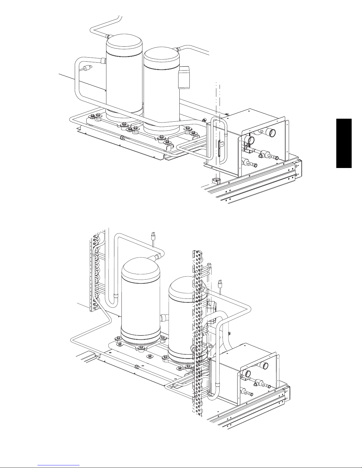
Fig. 26 -- 38AUD*16 Compressor Assembly (Rear View)
38AUD
C10088
Fig. 27 -- 38AUD*25 Compressor Assembly (Rear View)
C10091
31
Page 72
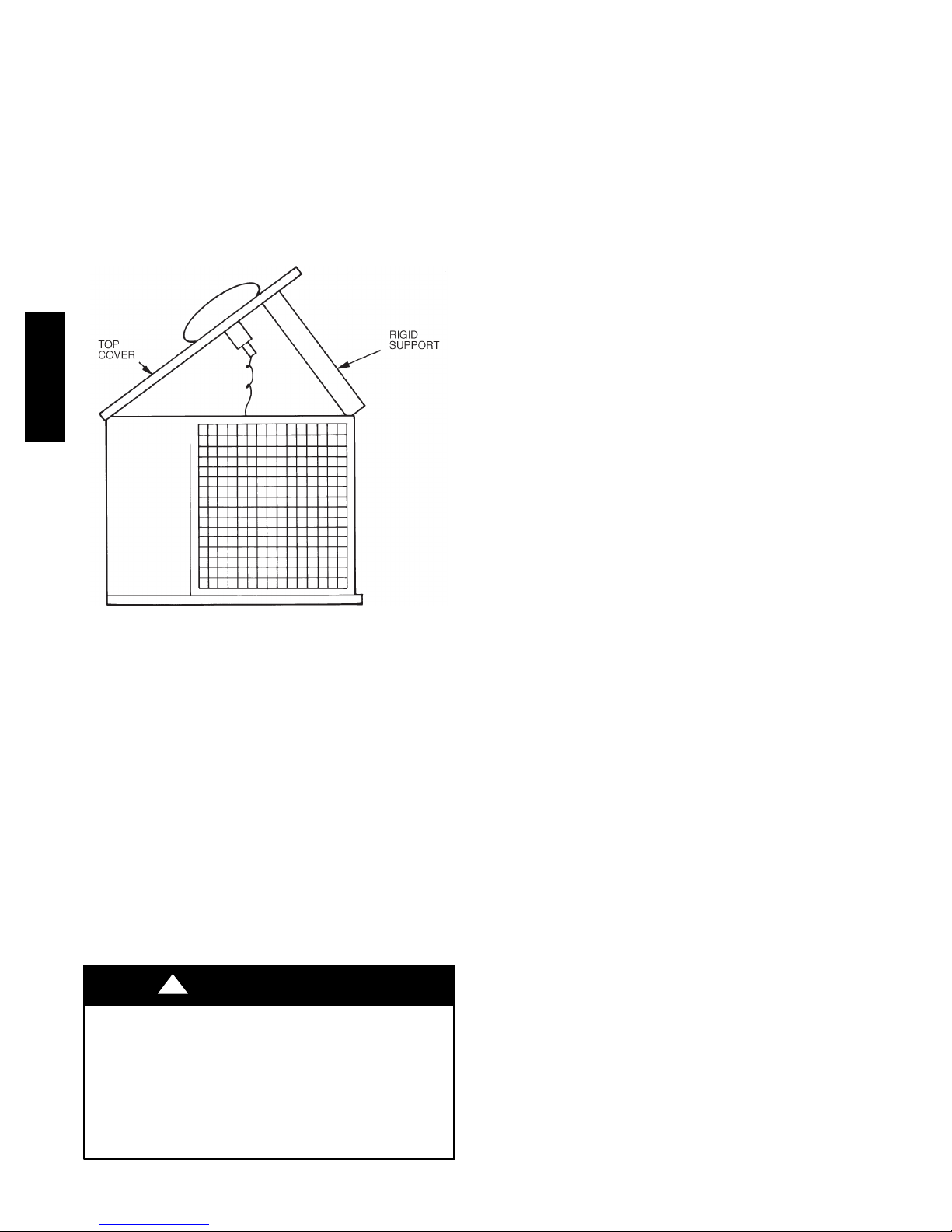
NOVATIONt Coil Cleaning and Maintenance — To
clean the NOVATION condenser coil, chemicals are NOT to
be used; only water is approved as the cleaning solution.
Only clean potable water is authorized for cleaning
NOVATION condensers.
Clean the coil as follows:
1. Turn off unit power.
2. Remove screws holding rear corner posts and top
cover in place. Pivot top cover up 305 to 457 mm (12
to 18 in.) and support with a rigid support. See
Fig. 27.
38AUD
Repairing NOVATION Condenser Tube Leaks
RCD offers service repair kit Part Number 50TJ660007 for
repairing tube leaks in the NOVATION coil crosstubes. This
kit includes approved braze materials (aluminum fluxcore
braze rods), a heat shield, a stainless steel brush, replacement
fin segments, adhesive for replacing fin segments, and
instructions specific to the NOVATION aluminum coil. See
EPIC for instruction sheet 99TA526379.
The repair procedure requires the use of MAPP gas and
torch (must be supplied by servicer) instead of conventional
oxyacetylene fuel and torch. While the flame temperature
for MAPP is lower than that of oxyacetylene (and thus
provides more flexibility when working on aluminum), the
flame temperature is still higher than the melting
temperature of aluminum, so user caution is required. Follow
instructions carefully. Use the heat shield.
Replacing NOVATION Condenser Coil
The service replacement coil is preformed and is equipped
with transition joints with copper stub tubes. When
brazing the connection joints to the unit tubing, use a wet
cloth around the aluminum tube at the transition joint.
Avoid applying torch flame directly onto the aluminum
tubing.
C10092
Fig. 28 -- Pivot and Support Top Cover
3. Carefully remove any foreign objects or debris attached to the coil face or trapped within the mounting
frame and brackets.
4. Using a high pressure water sprayer, purge any soap
or industrial cleaners from hose and/or dilution tank
prior to wetting the coil. Clean condenser face by
spraying the coil core steadily and uniformly from top
to bottom, directing the spray straight into or toward
the coil face. Do not exceed 6205 kPa (900 psig) or a
45 degree angle; nozzle must be at least 30 cm
(12 in.) from the coil face. Reduce pressure and use
caution to prevent damage to air centers (fins). Do not
fracture the braze between air centers and refrigerant
tubes. Allow water to drain from the coil core and
check for refrigerant leaks prior to start up.
5. Replace top cover and rear corner posts.
!
CAUTION
EQUIPMENT DAMAGE HAZARD
Failure to follow this caution may result in equipment
damage.
Chemical cleaning should NOT be used on the
aluminum microchannel (NOVATION) condenser.
Damage to the coil may occur. Only approved
cleaning is recommended.
Routine Cleaning of Round-Tube Plate Fin (RTPF) Coils
— Periodic cleaning with Totaline
coil cleaner is essential to extend the life of RTPF coils. This
cleaner is available from Carrier Replacement parts division
as part number P902-0301 for a one gallon container, and
part number P902-0305 for a 5 gallon container. It is
recommended that all RTPF coils, with the exception of
NOVATION coils, be cleaned with the Totaline
environmentally sound coil cleaner as described below.
NOTE: Do NOT use Totaline
cleaner, or any other coil cleaner on NOVATION coils. See
“NOVATION Coil Cleaning and Maintenance” for
instructions on cleaning NOVATION coils.
Coil cleaning should be part of the unit’s regularly
scheduled maintenance procedures to ensure long life of
the coil. Failure to clean the coils may result in reduced
durability in the environment.
Avoid the use of:
S coil brighteners
S acid cleaning prior to painting
S high pressure washers
S poor quality water for cleaning
Totaline environmentally sound coil cleaner is
non-flammable, hypoallergenic, non-bacterial, and a
USDA accepted biodegradable agent that will not harm
the coil or surrounding components such as electrical
wiring, painted metal surfaces, or insulation. Use of
non-recommended coil cleaners is strongly discouraged
since coil and unit durability could be affected.
®
environmentally sound
®
environmentally sound coil
32
Page 73
Totaline Environmentally Sound Coil Cleaner
Application Equipment
1
S 2
/2gallon garden sprayer
S water rinse with low velocity spray nozzle
!
CAUTION
UNIT DAMAGE HAZARD
Failure to follow this caution may result in corrosion
and damage to the unit.
Harsh chemicals, household bleach or acid or basic
cleaners should not be used to clean outdoor or indoor
coils or any kind. These cleaners can be very difficult
to rinse out of the coil and can accelerate corrosion at
the fin/tube interface where dissimilar materials are in
contact. If there is dirt below the surface of the coil
use the Totaline environmentally sound coil cleaner as
described above.
!
CAUTION
UNIT RELIABILITY HAZARD
Failure to follow this caution may result in reduced
unit performance.
High velocity water from a pressure washer, garden
hose, or compressed air should never be used to clean
a coil. The force of the water or air jet will bend the
fin edges and increase airside pressure drop.
Totaline Environmentally Sound Coil Cleaner
Application Instructions
NOTE: Proper eye protection such as safety glasses is
recommended during mixing and application.
1. Turn off unit power.
2. Remove screws holding rear corner post and top cover
in place. Pivot top cover up 305 to 457 mm (12 to 18
in.) and support with a rigid support. See Fig. 27.
3. Remove all surface loaded fibers and dirt with a vacuum cleaner. If a vacuum cleaner is not available, a
soft non-metallic bristle brush may be used. In either
case, the tool should be applied in the direction of the
fins. Coil surfaces can be easily damaged (fin edges
can be easily bent over and damage to the coating of
a protected coil) if the tool is applied across the fins.
NOTE: Use of a water stream, such as a garden hose,
against surface loaded coil will drive the fibers and dirt
into the coil, making cleaning efforts more difficult.
Surface loaded fibers must be completely removed prior
to using low velocity clean water rinse.
4. Using a low velocity garden hose thoroughly wet
finned surfaces with clean water. Be careful not to
bend the fins.
5. Mix Totaline environmentally sound coil cleaner in a
1
/2gallon garden sprayer according to the instruc-
2
tions included with the cleaner. The optimum solution
temperature is 38°C (100°F).
NOTE: Do NOT USE water in excess of 54°C (130°F),
as the enzymatic activity will be destroyed.
6. Thoroughly apply Totaline environmentally sound
coil cleaner solution to all coil surfaces including the
finned area, tube sheets and coil headers.
7. Hold garden sprayer nozzle close to finned areas and
apply cleaner with a vertical, up-and-down motion.
Avoid spraying in horizontal pattern to minimize potential for fin damage.
8. Ensure cleaner thoroughly penetrates deep into finned
areas.
9. Interior and exterior finned areas must be thoroughly
cleaned.
10. Finned surfaces should remain wet with cleaning
solution for 10 minutes.
11. Ensure surfaces are not allowed to dry before rinsing.
Reapply cleaner as needed to ensure 10-minute saturation is achieved.
12. Thoroughly rinse all surfaces with low velocity clean
water using downward rinsing motion of water spray
nozzle. Protect fins from damage from the spray
nozzle.
13. Replace top cover and rear corner posts.
38AUD
Compressor mounting bolts 734–847 N–cm (120--- 168 in–lbs)
Condenser fan motor mounting bolts 226 ±23 N–cm (20 ±2in–lbs)
Condenser fan hub setscrew 949 ±136 N–cm (84 ±2in–lbs)
High-flow service port 1085 ±23 N–cm (96 ±10 in–lbs)
Schrader-type service check valve 23–34 N–cm (2–3 in–lbs)
Compressor oil sightglass thread 3730 ±340 N ---cm (330 ±31 in–lbs)
FASTENER TORQUE VALUES
Table 11 – Torque Values
33
Page 74
PROBLEM SOLUTION
COMPRESSOR DOES NOT R UN
Contactor Open
1. Power off. 1. Restore power.
2. Fuses blown in field power circuit. 2. After finding cause and correcting, replace with correct size fuse.
3. No control power. 3. Check control transformer primary connections and circuit breaker.
4. Thermostat circuit open. 4. Check thermostat setting.
5. Safety device lockout circuit active. 5. Reset lockout circuit.
6. Low-pressure switch open. 6. Check for refrigerant undercharge, obstruction of indoor airflow. Make
7. High-pressure switch open. 7. Check for refrigerant overcharge, obstruction of outdoor airflow, air in system.
8. Compressor overtemperature switch open . 8. Check for open condition. Allow for reset. Replace if defective.
9. Loose electrical connections. 9. Tighten all connections.
10. Compressor stuck. 10. See compressor service literature.
Contactor Closed
38AUD
1. Compressor leads loose. 1. Check connections.
2. Motor windings open. 2. See compressor service literature.
3. Single phasing. 3. Check for blown fuse. Check for loose connection at compressor terminal.
COMPRESSOR STOPS ON HIGH-PRESSURE SWITCH
Outdoor Fan On
1. High-pressure switch faulty. 1. Replace switch.
2. Reversed fan rotation. 2. Confirm rotation, correct if necessary.
3. Airflow restricted. 3. Remove obstruction.
4. Air recirculating. 4. Clear airflow area.
5. Noncondensables in system. 5. Recover refrigerant and recharge as required.
6. Refrigerant overcharge. 6. Recover refrigerant as required.
7. Line voltage incorrect. 7. Consult power company.
8. Refrigerant system restrictions. 8. Check or replace filter drier, expansion valve, etc.
Outdoor Fan Off
1. Fan slips on shaft. 1. Tighten fan hub setscrews.
2. Motor not running. 2. Check power and capacitor.
3. Motor bearings stuck. 3. Replace bearings.
4. Motor overload open. 4. Check overload rating. Check for fan blade obstruction.
5. Motor burned out. 5. Replace motor.
COMPRESSOR CYCLES ON LOW-PRESSURE SWITCH
Indoor-Air Fan Running
1. Liq uid line solenoid valve(s) fails to open. 1. Check liquid line solenoid valve(s) for proper operation. Replace if necessary.
2. Filter drier plugged. 2. Replace filter drier.
3. Expansion valve power head defective. 3. Replace power head.
4. Low refrigerant charge. 4. Add charge. Check low-pressure switch setting.
Airflow Restricted
1. Coil iced up. 1. Check refrigerant charge.
2. Coil dirty. 2. Clean coil fins.
3. Air filters dirty. 3. Clean or replace filters.
4. Dampers closed. 4. Check damper operation and p osition.
Indoor-Air Fan Stopped
1. Electrical connections loose. 1. Tighten all connections.
2. Fan relay defective. 2. Replace relay.
3. Motor overload open. 3. Power supply.
4. Motor defective. 4. Replace motor.
5. Fanbeltbrokenorslipping. 5. Replace or tighten belt.
TROUBLESHOOTING
sure liquid line solenoid valve(s) is open.
Be sure outdoor fans are operating correctly.
34
Page 75

TROUBLESHOOTING (cont)
PROBLEM SOLUTION
COMPRESSOR RUNNING BUT COOLING INSUFFICIENT
Suction Pressure Low
1. Refrigerant charge low. 1. Add refrigerant.
2. Head pressure low. 2. Check refrigerant charge. Check outdoor-air fan thermostat settings.
3. Air filters dirty. 3. Clean or replace filters.
4. Expansion valve power head defective. 4. Replace power head.
5. Indoor coil partially iced. 5. Check low-pressure setting.
6. Indoor airflow restricted. 6. Remove obstruction.
Suction Pressure High
1. Unloaders not functioning 1. Check unloader adjustments. Check unloader setting.
2. Heat load excessive. 2. Check for open doors or windows in vicinity of fan coil.
UNIT OPERATES TOO LONG OR CONTINUOUSLY
1. Low refrigerant charge. 1. Add refrigerant.
2. Control contacts fused. 2. Replace control.
3. Air in system. 3. Purge and evacuate system.
4. Partially plugged expansion valve or filter drier. 4. Clean or replace.
SYSTEM IS NOISY
1. Piping vibration. 1. Support piping as required.
2. Compressor noisy. 2. Replace compressor if bearings are worn.
COMPRESSOR LOSES OIL
1. Leak in system. 1. Repair leak.
2. Crankcase heaters not energized during shutdown. 2. Check wiring and relays. Check heater and replace if defective.
3. Improper interconnecting piping design. 3. Check piping for oil return. Replace if necessary.
FROSTED SUCTION LINE
Expansion valve admitting excess refrigerant. Adjust expansion valve.
HOT LIQUID LINE
1. Shortage of refrigerant due to leak. 1. Repair leak and recharge.
2. Expansion valve opens too wide. 2. Adjust expansion valve.
FROSTEDLIQUIDLINE
1. Restricted filter drier. 1. Remove restriction or replace.
2. Liquid line solenoid valve partially closed. 2. Replace valve.
38AUD
35
Page 76
APPENDIX A
AIR CONDITIONER & HEAT PUMP WITH
PURON®— QUICK REFERENCE GUIDE
S Puron®(R-410A) refrigerant operates at 50 percent to
70 percent higher pressures than R-22. Be sure that
servicing equipment and replacement components are
designed to operate with Puron®.
S Puron® refrigerant cylinders are rose colored.
S Recovery cylinder service pressure rating must be
2758 kPa (400 psig), DOT 4BA400 or DOT BW400.
S Puron® systems should be charged with liquid
refrigerant. Use a commercial type metering device in
the manifold hose when charging into suction line with
compressor operating.
S Manifold sets should be 4826 kPa (700 psig) high side
38AUD
and 180 psig low side with 3290 kPa (550 psig)
low-side retard.
S Use hoses with 4826 kPa (700 psig) service pressure
rating.
S Leak detectors should be designed to detect HFC
refrigerant.
S Puron®, as with other HFCs, is only compatible with
POE oils.
S Vacuum pumps will not remove moisture from oil.
S Use only factory specified liquid-line filter driers with
rated working pressures greater than 4137kPa (600 psig).
S Do not install a suction-line filter drier in liquid-line.
S POE oils absorb moisture rapidly. Do not expose oil to
atmosphere.
S POE oils may cause damage to certain plastics and
roofing materials.
S Wrap all filter driers and service valves with wet cloth
when brazing.
S A factory approved, liquid-line filter drier is required on
every unit.
S Do not use an R-22 TXV.
S If indoor unit is equipped with a TXV, it must be
®
changedtoaPuron
TXV.
S Never open system to atmosphere while it is under a
vacuum.
S When system must be opened for service, recover
refrigerant, break vacuum with dry nitrogen before
opening system.
S Always replace filter drier after opening system for
service.
®
S Do not vent Puron
into the atmosphere.
S Do not use capillary tube coils.
S Observe all warnings, cautions,andbold text.
®
S All Puron
S Do not leave Puron
heat pumps must have indoor TXV.
®
suction line driers in place for
more than 72 hours.
APPENDIX B
WIRING DIAGRAM LIST
Unit Electrical Characteristics Diagram Number
38AD*16 400---3---50 38AU500824
38AD*25 400---3---50 38AU500825
36
Page 77

APPENDIX C
r
MOTORMASTER SENSOR LOCATIONS
Motormaster
Sensor
Motormaster Senso
Must be positioned
on Vapor Stub
38AUD
254 mm (10 in)
Fig. 29 -- Motormaster Sensor Location:
38AUD*16
C10093
C10094
Fig. 30 -- Motormaster Sensor Location:
38AUD*25
37
Page 78
38AUD
Copyright 2010 Ca rrier Corp. D 7310 W. Morris St. D Indianapolis, IN 46231 Printed in U.S.A. Edition Date: 01/10
Manufacturer reserves the right to change, at any time, specifications and designs without notice and without obligations.
Catalog No: 38AU ---C02SI
Replaces: New
38
Page 79
START-UP CHECKLIST
I. PRELIMINARY INFORMATION
OUTDOOR: MODEL NO. SERIAL NO.
INDOOR: AIRHANDLER MANUFACTURER
MODEL NO. SERIAL NO.
ADDITIONAL ACCESSORIES
II. PRE-START-UP
OUTDOOR UNIT
IS THERE ANY SHIPPING DAMAGE? (Y/N)
IF SO, WHERE:
WILL THIS DAMAGE PREVENT UNIT START-UP? (Y/N)
CHECK POWER SUPPLY. DOES IT AGREE WITH UNIT? (Y/N)
HAS THE GROUND WIRE BEEN CONNECTED? (Y/N)
HAS THE CIRCUIT PROTECTION BEEN SIZED AND INSTALLED PROPERLY? (Y/N)
ARE THE POWER WIRES TO THE UNIT SIZED AND INSTALLED PROPERLY? (Y/N)
CONTROLS
ARE THERMOSTAT AND INDOOR FAN CONTROL WIRING CONNECTIONS MADE AND CHECKED?
(Y/N)
ARE ALL WIRING TERMINALS (including main power supply) TIGHT? (Y/N)
HAS CRANKCASE HEATER BEEN ENERGIZED FOR 24 HOURS? (Y/N)
INDOOR UNIT
HAS WATER BEEN PLACED IN DRAIN PAN TO CONFIRM PROPER DRAINAGE? (Y/N)
ARE PROPER AIR FILTERS IN PLACE? (Y/N)
HAVE FAN AND MOTOR PULLEYS BEEN CHECKED FOR PROPER ALIGNMENT? (Y/N)
DO THE FAN BELTS HAVE PROPER TENSION? (Y/N)
HAS CORRECT FAN ROTATION BEEN CONFIRMED? (Y/N)
PIPING
ARE LIQUID LINE SOLENOID VALVES LOCATED AT THE INDOOR COILS AS REQUIRED? (Y/N)
38AUD
HAVE LEAK CHECKS BEEN MADE AT COMPRESSOR, OUTDOOR AND INDOOR COILS,
TXVs (Thermostatic Expansion Valves), SOLENOID VALVES, FILTER DRIERS, AND FUSIBLE PLUGS
WITH A LEAK DETECTOR? (Y/N)
LOCATE, REPAIR, AND REPORT ANY LEAKS.
HAVE LIQUID LINE SERVICE VALVES BEEN OPENED? (Y/N)
HAVE SUCTION SERVICE VALVES BEEN OPENED? (Y/N)
39
Page 80
CHECK VOLTAGE IMBALANCE
LINE-TO-LINE VOLTS: AB V AC V BC V
(AB + AC + BC)/3 = AVERAGE VOLTAGE = V
MAXIMUM DEVIATION FROM AVERAGE VOLTAGE = V
VOLTAGE IMBALANCE = 100 X (MAX DEVIATION)/(AVERAGE VOLTAGE) =
IF OVER 2% VOLTAGE IMBALANCE, DO NOT ATTEMPT TO START SYSTEM!
CALL LOCAL POWER COMPANY FOR ASSISTANCE.
CHECK INDOOR UNIT FAN SPEED AND RECORD.
CHECK OUTDOOR UNIT FAN SPEED AND RECORD.
AFTER AT LEAST 10 MINUTES RUNNING TIME, RECORD THE FOLLOWING MEASUREMENTS:
CIRCUIT 1 CIRCUIT 2
SUCTION PRESSURE
38AUD
SUCTION LINE TEMP
LIQUID PRESSURE
LIQUID LINE TEMP
ENTERING OUTDOOR UNIT AIR TEMP
LEAVING OUTDOOR UNIT AIR TEMP
INDOOR UNIT ENTERING-AIR DB (dry bulb) TEMP
INDOOR UNIT ENTERING-AIR WB (wet bulb) TEMP
INDOOR UNIT LEAVING-AIR DB TEMP
INDOOR UNIT LEAVING-AIR WB TEMP
COMPRESSOR AMPS (L1/L2/L3)
CIRCUIT 1 / /
CIRCUIT 2 / /
NOTES:
Copyright 2010 Ca rrier Corp. D 7310 W. Morris St. D Indianapolis, IN 46231 Printed in U.S.A. Edition Date: 01/10
Manufacturer reserves the right to change, at any time, specifications and designs without notice and without obligations.
Catalog No: 38AU ---C02SI
Replaces: New
40
 Loading...