


Fig. 1 — Typical 30RAP Unit (018-030 Shown)
30RAP010-150 Air-Cooled Chillers and
30RAP011-060 Air-Cooled Chillers
with Greenspeed® Intelligence
with Puron® Refrigerant (R-410A)
Installation Instructions
AquaSnap
50/60 Hz
®
CONTENTS
Page
SAFETY CONSIDERATIONS
INSTALLATION
Storage Recommendations . . . . . . . . . . . . . . . . . . . . . . 2
Step 1 — Place and Rig the Unit
•PLACING UNIT
•RIGGING
• MOUNTING UNIT
Step 2 — Check Compressor Mounting
Step 3 — Connect Cooler Fluid and
Drain Piping
• ALL UNITS
• VICTAULIC COUPLING INSTALLATION
• UNITS WITH FACTORY-INSTALLED
HYDRONIC PACKAGES
•AIR SEPARATION
Step 4 — Fill the Chilled Water Loop
• WATER SYSTEM CLEANING
• FILLING THE SYSTEM
•PUMP VFD
• SENSORLESS CONTROL (CLOSED LOOP) —
ACTIVE SETUP 1
• REMOTE SENSOR (CLOSED LOOP) —
ACTIVE SETUP 2
• REMOTE CONTROLLER (OPEN LOOP) —
ACTIVE SETUP 3
• PREPARATION FOR YEAR-ROUND OPERATION
• FREEZE PROTECTION
• PREPARATION FOR WINTER SHUTDOWN
Step 5 — Make Electrical Connections
• POWER SUPPLY
•POWER WIRING
• CONTROL POWER
Step 6 — Install Accessories
• ELECTRICAL
Step 7 — Check Refrigerant Circuit
• LEAK TESTING
• DEHYDRATION
• REFRIGERANT CHARGE
BACnet Communication Option Wiring
APPENDIX A (PRESSURE DROP CURVES)
. . . . . . . . . . . . . . . . . . . . . . . . . . . . . . . 2-59
. . . . . . . . . . . . . . . . . . . . . . . . . . . . . . . . . . 16
. . . . . . . . . . . . . . . . . . . . .1,2
. . . . . . . . . . . . . . . . . . 2
. . . . . . . . . 16
. . . . . . . . . . . . 33
. . . . . . . . . . 44
. . . . . . . . . . . . . . . . . . . . 68
. . . . . . . . . . . . . 68
. . . . . . . . . 69
. . . 72-84
SAFETY CONSIDERATIONS
Installing, starting up, and servicing air-conditioning equip-
ment can be hazardous due to system pressures, electrical
com
ponents, and equipment location (roofs, elevated struc-
tures, etc.).
Only trained, qualified installers and service mechanics
should install, start up, and service
Untrained personnel can perform basic
tions such as cleaning coils. All other operations should be
performed by trained
When working on the equipment, observe precautions in the
literature an
equipment.
• Follow all safety codes.
d on tags, stickers, and labels attached to the
service personnel.
this equipment (Fig. 1).
maintenance func-
• Wear safety glasses and work gloves.
• Keep quenching cloth and fire extinguisher nearby when
brazing
• Use care in handling, rigging, and setting bulky
.
.
equipment.
WARNING
Electrical shock can cause personal injury and death. Shut off
all power to this equipment during installation. There may be
more than one disconnect switch. Tag all disconnect locations
to alert others not to restore power until work is completed.
WARNING
DO NOT USE TORCH to remove any component. System
contains oil and refrigerant under pressure.
To remove a component, wear protective gloves and goggles and proceed as follows:
a. Shut off electrical po
b. Recover refrigerant to relieve all pressure
tem using both high-pressure and low pressure ports.
c. Traces of vapor should be displaced with nitrogen
and the work area
erant in contact with an open flame produces toxic
gases.
d. Cut component connection tubing with tubing cutter
and rem
any oil that may come out of the lines and as a gage
for how much oil to add to the system.
e. Carefully unsweat remaining tubing stubs when nec-
essary. Oil can ignite when
Failure to follow these procedures may
injury or death.
ove component from unit. Use a pan to catch
wer to unit.
from sys-
should be well ventilated. Refrig-
exposed to torch flame.
result in personal
Manufacturer reserves the right to discontinue, or change at any time, specifications or designs without notice and without incurring obligations.
Catalog No. 04-53300163-01 Printed in U.S.A. Form 30RAP-16SI Pg 1 4-16 Replaces: 30RAP-13SI
CAUTION
6 ft
(1.8 m)
MINIMUM*
3.5 ft (1.1 m)
MINIMUM†
* Minimum for when coils face each other. Less clearance is
required in other configurations.
† Clearance of 3.5 ft is required when a coil faces the wall. When
there is no coil facing the wall, see the certified drawing for the
required service clearance.
a30-4873
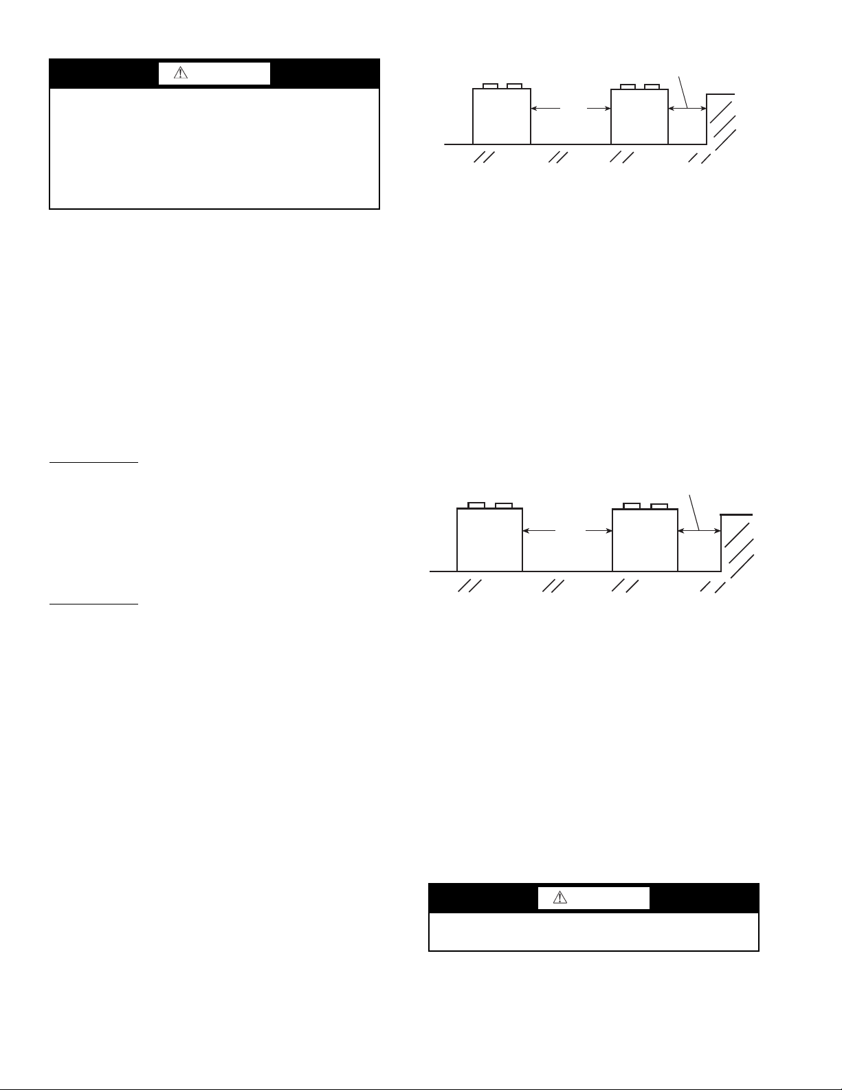
Fig. 2 — 30RAP010-060 Multiple Unit Separation
10 ft
(3 m)
MINIMUM
6 ft (1.8 m)
MINIMUM
a30-4904
Fig. 3 — 30RAP070-150 Multiple Unit Separation
DO NOT re-use compressor oil or any oil that has been
exposed to the atmosphere. Dispose of oil per local codes
and regulations. DO NOT leave refrigerant system open to
air any longer than the actual time required to service the
equipment. Seal circuits being serviced and charge with
dry nitrogen to prevent oil contamination when timely
repairs cannot be completed. Failure to follow these proce
-
dures may result in damage to equipment.
INSTALLATION
Storage Recommendations — The 30RAP air-
cooled chillers are designed for outdoor installations. At
times, a delay in construction or other factors require that a
unit be stored for a period of time prior to installation. The
following guidelines should be used for unit storage.
PROVIDE MACHINE PROTECTION — Place and store
the unit in an area that will protect it from vandalism, acciden
tal contact with vehicles, falling debris or construction waste.
Ideally, do not remove the shipping protection such as the coil
protectors. This will provide additional protection for the unit.
The unit can be stored outdoors.
INSPECTION DURING STORAGE — To ensure faster
installation when the time comes, the following inspection
schedule is recommended:
Every 3 Months — The 30RAP units are shipped with a complete operating charge of R-410A. Check each refrigerant circuit to be sure that there is positive pressure, at least 26 psig
(180 kPa) in the circuit. If a circuit is found to be without pres
sure, contact a qualified refrigeration mechanic. The system
should be pressurized to find the leak. It should be repaired, dehydrated and recharged with refrigerant. If a positive circuit
pressure was not found, the compressor oil should be changed
or at least sampled to determine if moisture is present. If mois
ture is found in the compressor oil, the oil should be changed.
Every 6 Months — Check the unit for damage, both physical
and from wildlife. Check the unit for nests from rodents, birds,
or insects. Depending on location, these organisms can cause
deterioration of components which may result in failure. Con
sider an exterminator if necessary. If damage is found and it
will interfere with the installation, consider repairing the dam
age before installation. Check the unit control box for signs of
moisture. If moisture is found, determine the entry path and
seal the leak.
Step 1 — Place and Rig the Unit
PLACING UNIT — Units are suitable for outdoor use only.
For 30RAP010-060 units, see Fig.
are aligned such that coils face each other, a minimum of
6
ft (1829 mm) separation is recommended. When the parallel arrangement has only one coil drawing air from the space
between chillers, a minimum of 3.5 ft (1067 mm) is recom
mended. When parallel chillers have no coils facing each
other (a back-to-back arrangement), be sure to maintain the
larger of the recommended service clearances associated
with each chiller (see the certified drawings). Due to NEC
(National Electric Code) regulations, a minimum clearance
of 4
ft (1219 mm) must be maintained on the side of the
chiller that has an electrical box. Chiller fan discharge must
be at least as high as adjacent solid walls. Installation in pits
is not recommended.
2. When parallel chillers
For 30RAP070-150 units, see Fig. 3. When chillers are arranged in parallel, a minimum of 10 ft (3048 mm) between
chillers is recommended. Acceptable clearance on the cooler
connection side or end opposite the control box of the unit can
be reduced to 3 ft (1 m) without sacrificing performance as
-
long as the remaining three sides are unrestricted. Acceptable
clearance on the side with a control box can be reduced to 4 ft
(1.3 m) due to NEC (National Electric Code) regulations, with
out sacrificing performance as long as the remaining three
sides are unrestricted. Clearances between chillers in dual
chiller applications may be reduced to 6 ft (1.8 m) without sac
rificing performance provided the remaining sides are unrestricted. For acceptable clearance with layout involving more
than 2 chillers, please contact application engineering.
-
-
-
-
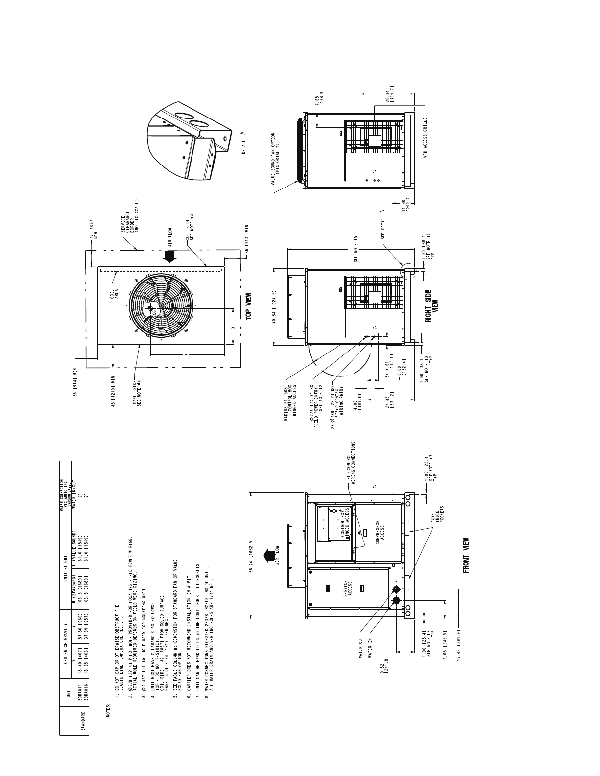
These instructions cover installation of 30RAP010-150 air-
cooled liquid chillers. Refer to Fig.
4 and 5 for model number
to determine factory-installed options.
RIGGING — Preferred method for rigging is with spreader
bars from above the unit. Use shackles in lifting holes. Rig at a
single point with 4 cables for size 010-115 units, 6 cables for size
130 and 150 units, or use spread bars. All panels must be in place
when rigging. See rigging label on unit for details concerning
shipping weights, distance between lifting holes, center of gravi
ty, and lifting ring dimensions. See Tables 1-3 and Fig. 6 for
unit weights. See Tables 4 and 5 for physical data. See Fig. 7
and 8 for rigging label.
If overhead rigging is not possible, place chiller on skid or
-
pad for rolling or dragging. When rolling, use a minimum of
3 rollers. When dragging, pull the pad. Do not apply force to
the unit. When in final position, raise from above to lift unit
off pad.
CAUTION
All panels must be in place when rigging. If they are not,
damage to unit could result.
2

Fig. 4 — AquaSnap® Chiller Model Number Designation, 30RAP010-060
LEGEND
EMM —
Energy Management Module
GFI —
Ground Fault Interrupting
MCHX —
Microchannel Heat Exchanger
SCCR — Short Circuit Current Rating
a30-5718
*High-efficiency variable condenser fans (codes D, F, G, H, J, and K)
are not available on unit sizes 010 and 015, and are the only choices
for sizes 011 and 016.
†Digital compressors (codes 2, 5, 8, C, G, and K) are not available on
unit sizes 011 and 016.
P00030RA 0 66D010
30RA
–
Air-Cooled AquaSnap Chiller
Refrigerant Type
P – Puron
Revision Level
C –
Current Revision Level
Unit Sizes
010 020 045
011 025 050
015 030 055
016 035 060
018 040
Voltage
1 –
575-3-60
2 –
380-3-60
5 –
208/230-3-60
6 –
460-3-60
9 –
380/415-3-50
Condenser Coil and Low Sound Options
5 –
MCHX, Value Sound Fan
6 –
MCHX, E-Coat, Value Sound Fan
D –
MCHX, AeroAcoustic Fan
F –
MCHX, E-Coat, AeroAcoustic Fan
J –
MCHX, AeroAcoustic Fan, Compressor Blanket(s)
K –
MCHX, E-Coat, AeroAcoustic Fan, Compressor Blanket(s)
Hydronic System
0 –
No Pump
2 –
Single Pump, 1.5 Hp
3 –
Single Pump, 3 Hp
4 –
Single Pump, 3 Hp High Head
5 –
Single Pump, 5 Hp
6 –
Single Pump, 5 Hp High Head
7 –
Single Pump, 7.5 Hp
Z –
Single Pump, 10 Hp
9 –
Dual Pump, 1.5 Hp
B –
Dual Pump, 3 Hp
C –
Dual Pump, 3 Hp High Head
D –
Dual Pump, 5 Hp
F –
Dual Pump, 5 Hp High Head
G –
Dual Pump, 7.5 Hp
H – Dua
l Pump, 10 Hp
Ambient/Capacity Control/High SCCR Options*†
0 –
Std Comp
1 –
Hot Gas Bypass
2 –
Digital Comp
3 –
Std Comp, High SCCR
4 –
Hot Gas Bypass, High SCCR
5 –
Digital Comp, High SCCR
6 –
Low Ambient, Std Comp
7 –
Low Ambient, Hot Gas Bypass
8 –
Low Ambient, Digital Comp
9 –
Low Ambient, Std Comp, High SCCR
B –
Low Ambient, Hot Gas Bypass, High SCCR
C –
Low Ambient, Digital Comp, High SCCR
D –
Std Comp, High-Efficiency Variable Condenser Fans
F –
Hot Gas Bypass, High-Efficiency Variable Condenser Fans
G –
Digital Comp, High-Efficiency Variable Condenser Fans
H –
Std Comp, High SCCR, High-Efficiency Variable
Condenser Fans
J –
Hot Gas Bypass, High SCCR, High-Efficiency Variable
Condenser Fans
K –
Digital Comp, High SCCR, High-Efficiency Variable
Condenser Fans
Electrical Options
0 –
No Disconnect, No Cooler Heater
1 –
No Disconnect, Cooler Heater
D –
Non-Fused Disconnect, No Cooler Heater
F –
Non-Fused Disconnect, Cooler Heater
Controls/Communications Options
0 –
Std
1 –
Std, BACnet Communication
5 –
EMM
6 – EMM,
BACnet Communication
B –
EMM, GFI
C – EMM, GFI,
BACnet Communication
H – GFI
J – GFI,
BACnet Communication
Packaging/Security Options
0 –
Std Packaging
4 –
Security Grilles/Hail Guards Only
8 –
Skid Only
D –
Skid, Security Grilles/Hail Guards
J –
Skid, Top Crate, Bag
N –
Skid, Top Crate, Bag, Security Grilles/Hail Guards
®
C
a30-6071
3

LEGEND
EMM —
Energy Management Module
GFI —
Ground Fault Interrupting
MCHX —
Microchannel Heat Exchanger
SCCR — Short Circuit Current Rating
VFD —
Variable Frequency Drive
Fig. 5 — AquaSnap® Chiller Model Number Designation, 30RAP070-150
P00030RA 0 66D070
30RA
–
Air-Cooled AquaSnap Chiller
Refrigerant Type
P – Puron
Revision Level
B –
Current Revision Level
Unit Sizes
070 115
080 130
090 150
100
Voltage
1 –
575-3-60
2 –
380-3-60
5 –
208/230-3-60
6 –
460-3-60
9 –
380/415-3-50
Condenser Coil and Low Sound Options
0 –
Aluminum/Copper, Value Sound Fan
1 –
Copper/Copper, Value Sound Fan
2 –
Aluminum/Copper, Pre-Coat, Value Sound Fan
3 –
Aluminum/Copper, E-Coat, Value Sound Fan
4 –
Copper/Copper, E-Coat, Value Sound Fan
5 –
MCHX, Value Sound Fan
6 –
MCHX, E-Coat, Value Sound Fan
7 –
Aluminum/Copper, AeroAcoustic™ Fan
8 –
Copper/Copper, AeroAcoustic Fan
9 –
Copper/Aluminum, Pre-Coat, AeroAcoustic Fan
B – Copper/
Aluminum, E-Coat, AeroAcoustic Fan
C –
Copper/Copper, E-Coat, AeroAcoustic Fan
D –
MCHX, AeroAcoustic Fan
F –
MCHX, E-Coat, AeroAcoustic Fan
J –
MCHX, AeroAcoustic Fan, Compressor Blanket(s)
K –
MCHX, E-Coat, AeroAcoustic Fan, Compressor Blanket(s)
L –
Aluminum/Copper, AeroAcoustic Fan, Compressor Blanket(s)
M –
Copper/Copper, AeroAcoustic Fan, Compressor Blanket(s)
N –
Aluminum/Copper, Pre-Coat, AeroAcoustic Fan, Compressor Blanket(s)
P –
Aluminum/Copper, E-Coat, AeroAcoustic Fan, Compressor Blanket(s)
Q –
Copper/Copper, E-Coat, AeroAcoustic Fan, Compressor Blanket(s)
Hydronic System
Ambient/Capacity Control/High SCCR Options
0 –
Std Comp
1 –
Hot Gas Bypass
2 –
Digital Comp
3 –
Std Comp, High SCCR
4 –
Hot Gas Bypass, High SCCR
5 –
Digital Comp, High SCCR
6 –
Low Ambient, Std Comp
7 –
Low Ambient, Hot Gas Bypass
8 –
Low Ambient, Digital Comp
9 –
Low Ambient, Std Comp, High SCCR
B –
Low Ambient, Hot Gas Bypass, High SCCR
C –
Low Ambient, Digital Comp, High SCCR
D –
Std Comp, Suction Service Valve
F –
Hot Gas Bypass, Suction Service Valve
G –
Digital Comp, Suction Service Valve
H –
Std Comp, High SCCR, Suction Service Valve
J –
Hot Gas Bypass, High SCCR, Suction Service Valve
K –
Digital Comp, High SCCR, Suction Service Valve
L –
Low Ambient, Std Comp, Suction Service Valves
M –
Low Ambient, Hot Gas Bypass, Suction Service Valves
N –
Low Ambient, Digital Comp, Suction Service Valves
P –
Low Ambient, Std Comp, High SCCR, Suction Service
Valves
Q –
Low Ambient, Hot Gas Bypass, High SCCR, Suction Service
Valves
R –
Low Ambient, Digital Comp, High SCCR, Suction Service
Valves
Electrical Options
Controls/Communications Options
0 –
Std
1 –
Std, BACnet Communication
5 –
EMM
6 – EMM,
BACnet Communication
B –
EMM, GFI
C – EMM, GFI,
BACnet Communication
H – GFI
J – GFI,
BACnet Communication
Packaging/Security Options
0 –
Std Packaging
4 –
Security Grilles/Hail Guards Only
8 –
Skid Only
D –
Skid, Security Grilles/Hail Guards
J –
Skid, Top Crate, Bag
N –
Skid, Top Crate, Bag, Security Grilles/Hail Guards
®
0 –
No Pump
1 –
Single Pump, 3 Hp
2 –
Single Pump, 5 Hp
3 –
Single Pump, 7.5 Hp
4 –
Single Pump, 10 Hp
5 –
Single Pump, 15 Hp
6 –
Dual Pump, 3 Hp
7 –
Dual Pump, 5 Hp
8 –
Dual Pump, 7.5 Hp
9 –
Dual Pump, 10 Hp
B –
Dual Pump, 15 Hp
D –
Single Pump, 5 Hp with VFD
F –
Single Pump, 7.5 Hp with VFD
G –
Single Pump, 10 Hp with VFD
H –
Single Pump, 15 Hp with VFD
J –
Dual Pump, 3 Hp with VFD
K –
Dual Pump, 5 Hp with VFD
L –
Dual Pump, 7.5 Hp with VFD
M –
Dual Pump, 10 Hp with VFD
N –
Dual Pump, 15 Hp with VFD
0 – Single Point,
No Disconnect, No Cooler Heater
1 – Single Point,
No Disconnect, Cooler Heater
2 – Single Point,
Non-Fused Disconnect, No Cooler Heater
3 – Single Point,
Non-Fused Disconnect, Cooler Heater
4 – Dual Point,
No Disconnect, No Cooler Heater
5 – Dual Point,
No Disconnect, Cooler Heater
B
a30-6072
4

Table 1 — MCHX Unit Operating Weights
MCHX STANDARD UNITS
30RAP
SIZE
010 188 209 161 146 — — 704 010 86 95 73 66 — — 319
011 216 209 161 176 — — 762 011 98 95 73 80 — — 346
015 193 213 163 149 — — 718 015 88 97 74 67 — — 326
016 245 213 163 179 — — 800 016 111 97 74 81 — — 363
018 363 264 209 288 — — 1125 018 165 120 95 131 — — 510
020 365 266 211 290 — — 1133 020 166 121 96 132 — — 514
025 393 290 237 321 — — 1242 025 178 132 108 146 — — 564
030 405 301 246 331 — — 1283 030 184 136 112 150 — — 582
035 652 730 413 369 — — 2163 035 296 331 187 167 — — 981
040 704 697 390 394 — — 2185 040 319 316 177 179 — — 991
045 675 758 425 379 — — 2238 045 306 344 193 172 — — 1015
050 732 724 401 405 — — 2263 050 332 328 182 184 — — 1026
055 744 762 437 427 — — 2369 055 337 346 198 194 — — 1075
060 746 762 438 429 — — 2375 060 338 346 199 195 — — 1077
070 930 984 727 770 — — 3410 070 422 446 330 349 — — 1547
080 936 1038 791 877 — — 3641 080 425 471 359 398 — — 1652
090 952 1057 800 888 — — 3697 090 432 479 363 403 — — 1677
100 779 805 963 617 595 931 4690 100 353 365 437 280 270 422 2127
115 796 824 1027 697 672 991 5008 115 361 374 466 316 305 450 2272
130 1100 1179 1430 680 682 1380 6451 130 499 535 649 309 309 626 2926
150 1120 1205 1554 779 781 1499 6938 150 508 546 705 353 354 680 3147
A B C D E F Total Weight A B C D E F Total Weight
WEIGHT AT MOUNTING POINTS (lb)
30RAP
SIZE
MCHX SINGLE PUMP UNITS
30RAP
SIZE
010 215 264 213 174 — — 866 010 98 120 97 79 — — 393
011 243 264 213 204 — — 924 011 110 120 97 93 — — 419
015 220 268 215 177 — — 880 015 100 122 98 80 — — 399
016 272 268 215 207 — — 962 016 123 122 98 94 — — 436
018 404 306 249 329 — — 1288 018 183 139 113 149 — — 584
020 406 308 251 331 — — 1296 020 184 140 114 150 — — 588
025 434 332 277 362 — — 1405 025 197 151 126 164 — — 637
030 446 342 286 372 — — 1446 030 202 155 130 169 — — 656
035 677 877 537 415 — — 2507 035 307 398 244 188 — — 1137
040 728 846 513 441 — — 2529 040 330 384 233 200 — — 1147
045 701 906 550 425 — — 2582 045 318 411 249 193 — — 1171
050 756 873 524 453 — — 2606 050 343 396 238 206 — — 1182
055 768 910 561 474 — — 2713 055 349 413 254 215 — — 1231
060 771 910 562 476 — — 2719 060 350 413 255 216 — — 1233
070 1036 1032 871 874 — — 3812 070 470 468 395 396 — — 1729
080 1054 1070 963 948 — — 4035 080 478 485 437 430 — — 1830
090 1063 1082 967 950 — — 4061 090 482 491 438 431 — — 1842
100 1105 871 886 823 554 850 5089 100 501 395 402 373 252 385 2308
115 1121 892 948 904 631 912 5407 115 508 405 430 410 286 414 2453
130 1418 1252 1415 817 615 1333 6850 130 643 568 642 370 279 605 3107
150 1437 1280 1537 916 714 1453 7337 150 652 581 697 415 324 659 3328
A B C D E F Total Weight A B C D E F Total Weight
WEIGHT AT MOUNTING POINTS (lb)
30RAP
SIZE
MCHX DUAL PUMP UNITS
30RAP
SIZE
010 242 319 266 202 — — 1029 010 110 145 121 92 — — 467
011 270 319 266 232 — — 1087 011 123 145 121 105 — — 493
015 247 323 268 205 — — 1043 015 112 147 121 93 — — 473
016 299 323 268 235 — — 1125 016 136 147 121 107 — — 510
018 445 347 288 370 — — 1450 018 202 157 131 168 — — 658
020 447 349 290 372 — — 1458 020 203 158 132 169 — — 661
025 475 373 316 403 — — 1567 025 216 169 144 183 — — 711
030 487 383 325 413 — — 1608 030 221 174 147 187 — — 729
035 705 1022 664 459 — — 2850 035 320 463 301 208 — — 1293
040 755 992 639 486 — — 2872 040 343 450 290 221 — — 1303
045 729 1051 677 469 — — 2925 045 331 477 307 213 — — 1327
050 783 1019 649 499 — — 2950 050 355 462 295 226 — — 1338
055 796 1055 687 518 — — 3056 055 361 479 312 235 — — 1386
060 798 1056 688 520 — — 3062 060 362 479 312 236 — — 1389
070 1123 1036 928 1005 — — 4092 070 509 470 421 456 — — 1856
080 1159 1094 1038 1099 — — 4390 080 526 496 471 499 — — 1991
090 1167 1104 1041 1099 — — 4411 090 529 501 472 499 — — 2001
100 1353 908 820 990 506 797 5374 100 614 412 372 449 229 361 2438
115 1367 931 881 1070 583 860 5692 115 620 422 400 485 264 360 2582
130 1658 1297 1404 922 559 1295 7135 130 752 588 637 418 254 587 3236
150 1676 1326 1526 1020 659 1415 7622 150 760 601 692 463 299 642 3457
NOTE: See Fig. 6 for unit mounting points.
A B C D E F Total Weight A B C D E F Total Weight
WEIGHT AT MOUNTING POINTS (lb)
30RAP
SIZE
WEIGHT AT MOUNTING POINTS (kg)
WEIGHT AT MOUNTING POINTS (kg)
WEIGHT AT MOUNTING POINTS (kg)
5

Table 2 — RTPF Unit Operating Weights (
AL/CU COIL NO PUMP UNITS
Al/Cu Coil)
30RAP
SIZE
070 1017 1030 862 851 — — 3759 070 461 467 391 386 — — 1705
080
090
100
115
130
150
A B C D E F
1062 1100 968 935
1035 1153 1018 914
887 911 1179 724
913 940 1261 813
1183 1261 1596 763
1213 1296 1739 871
WEIGHT AT MOUNTING POINTS (lb)
— —
— —
702 1145
789 1223
765 1545
873 1682
Total
Weight
4064
4119
5548
5939
7113
7673
30RAP
SIZE
080
090
100
115
130
150
WEIGHT AT MOUNTING POINTS (kg)
A B C D E F
482 499 439 424
469 523 462 414
402 413 535 328
414 427 572 369
537 572 724 346
550 588 789 395
— —
— —
319 519
358 555
347 701
396 763
AL/CU COIL SINGLE PUMP UNITS
30RAP
SIZE
070 1126 1140 954 942 — — 4161 070 511 517 433 427 — — 1887
080
090
100
115
130
150
A B C D E F
1164 1206 1062 1025
1126 1255 1108 994
1215 982 1098 929
1240 1012 1178 1019
1506 1337 1577 901
1534 1373 1718 1009
WEIGHT AT MOUNTING POINTS (lb)
— —
— —
664 1059
750 1140
696 1495
804 1634
Total
Weight
4457
4483
5947
6338
7512
8072
30RAP
SIZE
080
090
100
115
130
150
WEIGHT AT MOUNTING POINTS (kg)
A B C D E F
528 547 482 465
511 569 502 451
551 445 498 421
562 459 534 462
683 606 715 409
696 623 779 458
— —
— —
301 480
340 517
316 678
365 741
AL/CU COIL DUAL PUMP UNITS
30RAP
SIZE
070 1201 1216 1018 1005 — — 4441 070 545 552 462 456 — — 2014
080
090
100
115
130
150
LEGEND
AL/CU — Aluminum Fin/Copper Tube
A B C D E F
1237 1282 1128 1089
1197 1333 1177 1057
1459 1023 1034 109
1483 1055 1113 1180
1744 1383 1565 1005
1771 1421 1706 1112
WEIGHT AT MOUNTING POINTS (lb)
— —
— —
622 1004
708 1085
641 1458
750 1597
Total
Weight
4737
4763
6232
6623
7797
8357
30RAP
SIZE
080
090
100
115
130
150
NOTE: See Fig. 6 for unit mounting points.
WEIGHT AT MOUNTING POINTS (kg)
A B C D E F
561 581 512 494
543 605 534 479
662 464 469 495
673 478 505 535
791 627 710 456
803 645 774 504
— —
— —
282 455
321 492
291 661
340 724
Total
Weight
1843
1868
2516
2694
3226
3480
Total
Weight
2022
2033
2697
2875
3407
3661
Total
Weight
2149
2160
2827
3004
3536
3790
6
Table 3 —
B
A
C
D
CONTROL
BOX
SIDE
30RAP010-030
UNITS
30RAP035-090
UNITS
a30-4861
Fig. 6 — Unit Mounting Points
30RAP100-150
UNITS
a30-5439
RTPF Unit Operating Weights (Cu/Cu Coil)
CU/CU COIL NO PUMP UNITS
30RAP
SIZE
WEIGHT AT MOUNTING POINTS (lb)
A B C D E F
Total
Weight
30RAP
SIZE
WEIGHT AT MOUNTING POINTS (kg)
A B C D E F
070 1179 1194 999 987 — — 4359 070 535 542 453 448 — — 1977
080
1250 1294 1140 1100
090
1216 1354 1196 1073
100
115
130
150
992 1016 1389 829
1033 1060 1501 933
1319 1395 1867 898
1363 1445 2039 1021
— —
— —
808 1354
909 1463
900 1814
1023 1981
4784
4839
6388
6899
8193
8873
080
090
100
115
130
150
567 587 517 499
552 614 542 487
450 461 630 376
469 481 681 423
598 633 847 407
— —
— —
366 614
412 664
408 823
618 655 925 463 464 899 4025
CU/CU COIL SINGLE PUMP UNITS
30RAP
SIZE
A B C D E F
WEIGHT AT MOUNTING POINTS (lb)
Total
Weight
30RAP
SIZE
070 1288 1304 1091 1078 — — 4761 070 584 591 495 489 — — 2160
080
1352 1401 1233 1191
090
1307 1456 1285 1154
100
1317 1090 1308 1030
115
1357 1135 1418 1135
130
1639 1474 1846 1035
150
1682 1525 2017 1158 955 1935 9272 150 763 692 915 525 433 878 4206
— —
— —
773 1268
873 1379
832 1766
5177
5203
6787
7298
8592
080
090
100
115
130
WEIGHT AT MOUNTING POINTS (kg)
A B C D E F
613 635 559 540
593 660 583 524
597 494 593 467
615 515 643 515
743 668 837 469
— —
— —
351 575
396 626
377 801
CU/CU COIL DUAL PUMP UNITS
30RAP
SIZE
A B C D E F
WEIGHT AT MOUNTING POINTS (lb)
Total
Weight
30RAP
SIZE
070 1364 1381 1156 1141 — — 5041 070 618 626 524 518 — — 2287
080
1425 1476 1300 1255
090
1378 1534 1355 1216
100
1558 1134 1246 1187
115
1597 1181 1356 1291
130
1875 1523 1834 1137
150
1917 1575 2004 1260
— —
— —
735 1211
836 1323
778 1730
902 1899
5457
5483
7072
7583
8877
080
090
100
115
130
9557 150 870 715 909 571 406 861 4335
LEGEND NOTE: See Fig. 6 for unit mounting points.
CU/CU — Copper Fin/Copper Tube
WEIGHT AT MOUNTING POINTS (kg)
A B C D E F
647 670 590 569
625 696 614 552
707 514 565 539
724 536 615 586
851 691 832 516
— —
— —
333 549
379 600
353 785
Total
Weight
2170
2195
2898
3129
3716
Total
Weight
2348
2360
3078
3310
3897
Total
Weight
2475
2487
3208
3440
4026
C
CONTROL
BOX
SIDE
B
A
B
CONTROL
BOX
SIDE
A
C
F
D
E
D
7
Table 4 —
Physical Data, 30RAP — English
UNIT 30RAP 010 011 015 016 018 020 025
OPERATING WEIGHT (lb)
MCHX Condenser Coil, No Pump 704 762 718 800 1125 1133 1242
MCHX Condenser Coil, Single Pump
(60 Hz only)
MCHX Condenser Coil, Dual Pump
(60 Hz only)
Al-Cu Condenser Coil, No Pump — — — — — — —
Al-Cu Condenser Coil, Single Pump
(60 Hz only)
Al-Cu Condenser Coil, Dual Pump
(60 Hz only)
Cu-Cu Condenser Coil, No Pump — — — — — — —
Cu-Cu Condenser Coil, Single Pump
(60 Hz only)
Cu-Cu Condenser Coil, Dual Pump
(60 Hz only)
REFRIGERANT TYPE R-410A, EXV Controlled System
Total Refrigerant Charge (lb) 8.6 8.3 9.6 10.0 14.6 15.2 16.7
Refrigerant Charge (lb) Ckt A/Ckt B 8.6/— 8.3/— 9.6/— 10.0/— 14.6/— 15.2/— 16.7/—
Total Refrigerant Charge RTPF (lb) — — — — — — —
Refrigerant Charge RTPF (lb)
Ckt A/Ckt B
COMPRESSORS Scroll, Hermetic
Quantity 1 2 1 2 2 2 2
Speed (Rpm)
(Qty) Tons, Ckt A (1) 11 (2) 6/4 (1) 15 (2) 9/6 (2) 9 (2) 10 (2) 13
(Qty) Tons, Ckt B — — — — — — —
Oil Charge (Pt) Ckt A/Ckt B 6.9/— 6.4/—
No. Capacity Steps
Standard 1 2 1 2 2 2 2
With Hot Gas Bypass — — — — 3 3 3
Digital Compressor Option 13 21 13 21 22 22 22
Minimum Capacity Step (%)
Standard 100 40 100 40 50 50 50
With Hot Gas Bypass — — — — 20 24 29
Digital Compressor Option 20 20 20 20 17 17 17
Capacity (%)
Circuit A 100 100 100 100 100 100 100
Circuit B — — — — — — —
COOLER Brazed, Direct-Expansion Plate Heat Exchanger
Weight (lb) (empty) 22.4 22.4
Net Fluid Volume (gal) 0.6 0.6 0.8 0.9 0.9 1.2 1.4
Maximum Refrigerant Pressure (psig) 505 505 505 505 505 505 505
Maximum Water-Side Pressure
Without Pump(s) (psig)
Maximum Water-Side Pressure
With Pump(s) (psig)
CHILLER WATER CONNECTIONS (in.)
Inlet and Outlet, Victaulic (IPS Carbon Steel)* 2 2 2 2 2 2 2
Drain (NPT)
CONDENSER FANS
Standard Low-Sound AeroAcoustic™ Type Plastic Type, Axial, Vertical Discharge
Fan Speed (Rpm) 850 (60 Hz)/710 (50 Hz)
No. Blades...Diameter (in.) 9...30 9...30 9...30 9...30 9...30 9...30 9...30
No. Fans 1 1 1 1 2 2 2
Total Airflow 60 Hz (Cfm) 9400 9400 9400 9400 17,500 17,500 19,400
Total Airflow 50 Hz (Cfm) 7849 7849 7849 7849 14,613 14,613 16,199
Optional Value Sound Type
Fan Speed (Rpm) 1140 (60 Hz)/950 (50 Hz)
No. Blades...Diameter (in.) 4...30 4...30 4...30 4...30 4...30 4...30 4...30
No. Fans 1 1 1 1 2 2 2
Total Airflow 60 Hz (Cfm) 10,100 10,100 10,100 10,100 18,500 18,500 20,900
Total Airflow 50 Hz (Cfm) 8434 8434 8434 8434 15,448 15,448 17,452
CONDENSER COILS Novation
Quantity (Ckt A/Ckt B) 1/— 1/— 1/— 1/— 1/— 1/— 1/—
Total Face Area (sq ft) 17 19 17 19 26 26 33
Maximum Refrigerant Pressure (psig) 656 656 656 656 656 656 656
HYDRONIC MODULE (Optional, 60 Hz only)†
Pump Single or Dual, Centrifugal Monocell Pump(s), 3500 Rpm. D
Expansion Tank Volume (gal)
Total/Acceptance 4.4/3.2
CHASSIS DIMENSIONS (ft - in.)
Length 5-7 5-7 5-7 5-7 7-5 7-5 7-5
Width 3-5 3-5 3-5 3-5 3-5 3-5 3-5
Height 5-6 5-6 5-6 5-6 5-6 5-6 6-6
EXV — Electronic Expansion Valve
MCHX — Microchannel Heat Exchanger
RTPF — Round Tube, Plate Fin (Condenser Coil)
LEGEND
866 924 880 962 1288 1296 1405
1029 1087 1043 1125 1450 1458 1567
— — — — — — —
— — — — — — —
— — — — — — —
— — — — — — —
— — — — — — —
3500 (60 Hz)/2900 (50 Hz)
6.9/—
9.1/—
13.8/— 13.8/— 13.8/—
27.5 31.8 31.8 40.3 46.3
300 300 300 300 300 300 300
150 150 150 150 150 150 150
1
/
4
Pump(s), Strainer with Blowdown Valve, Expansion Tank,
1
/
4
1
/
4
Propeller Type, Axial, V
®
MCHX Aluminum Tube, Aluminum Fin
*Unit connection is IPS Carbon Steel piping.
†Flow switch and strainer are standard on all units, with or without hydronic
package.
NOTE: 30RAP chillers with Greenspeed
sizes 010, 015, and 070-150.
1
/
4
1
/
4
1
/
4
ertical Discharge
Pressure Taps, Drain and Vent Plugs, Flow Switch, and
Balance Valve
ual pumps with check valves and isolation valves.
®
intelligence are not available on unit
1
/
4
8

Table 4 — Physical Data, 30RAP — English (cont)
UNIT 30RAP 030 035 040 045 050 055 060
OPERATING WEIGHT (lb)
MCHX Condenser Coil, No Pump 1283 2163 2185 2238 2263 2369 2375
MCHX Condenser Coil, Single Pump
(60 Hz only)
MCHX Condenser Coil, Dual Pump
(60 Hz only)
Al-Cu Condenser Coil, No Pump — — — — — — —
Al-Cu Condenser Coil, Single Pump
(60 Hz only)
Al-Cu Condenser Coil, Dual Pump
(60 Hz only)
Cu-Cu Condenser Coil, No Pump — — — — — — —
Cu-Cu Condenser Coil, Single Pump
(60 Hz only)
Cu-Cu Condenser Coil, Dual Pump
(60 Hz only)
REFRIGERANT TYPE
Total Refrigerant Charge (lb) 19.6 29.2 29.9 33.5 33.7 34.3 34.5
Refrigerant Charge (lb) Ckt A/Ckt B 19.6/— 14.3/14.9 14.9/15.0 16.5/17.0 16.7/17.0 16.9/17.4 17.1/17.4
Total Refrigerant Charge RTPF (lb) — — — — — — —
Refrigerant Charge RTPF (lb)
Ckt A/Ckt B
COMPRESSORS
Quantity 2 4 4 4 4 4 4
Speed (Rpm) 3500 (60 Hz)/2900 (50 Hz)
(Qty) Tons, Ckt A (2) 15 (2) 10 (2) 10 (2) 11 (2) 13 (2) 13 (2) 15
(Qty) Tons, Ckt B — (2) 9 (2) 11 (2) 13 (2) 13 (2) 15 (2) 15
Oil Charge (Pt) Ckt A/Ckt B
No. Capacity Steps
Standard 2 4 4 4 4 4 4
With Hot Gas Bypass 3 5 5 5 5 5 5
Digital Compressor Option 22 44 44 44 44 44 44
Minimum Capacity Step (%)
Standard 50 23 23 24 25 23 25
With Hot Gas Bypass 32 9 11 12 14 13 16
Digital Compressor Option 17 9 8 8 8 8 8
Capacity (%)
Circuit A 100 54 47 47 50 46 50
Circuit B — 46 53 53 50 54 50
COOLER
Weight (lb) (empty) 99.3 99.4
Net Fluid Volume (gal) 2.62 2.6 3.3 3.5 4.1 5.0 5.0
Maximum Refrigerant Pressure (psig) 565 565 565 565 565 565 565
Maximum Water-Side Pressure
Without Pump(s) (psig)
Maximum Water-Side Pressure
With Pump(s) (psig)
CHILLER WATER CONNECTIONS (in.)
Inlet and Outlet, Victaulic (IPS Carbon Steel)* 2 2
Drain (NPT)
CONDENSER FANS
Standard Low-Sound AeroAcoustic™ Type Plastic Type, Axial, Vertical Discharge
Fan Speed (Rpm) 850 (60 Hz)/710 (50 Hz)
No. Blades...Diameter (in.) 9...30 9...30 9...30 9...30 9...30 9...30 9...30
No. Fans 2 3 3 3 3 4 4
Total Airflow 60 Hz (Cfm) 19,400 29,600 29,600
Total Airflow 50 Hz (Cfm) 16,199 24,716 24,716 25,468 25,468 32,398 32,398
Optional Value Sound Type
Fan Speed (Rpm) 1140 (60 Hz)/950 (50 Hz)
No. Blades...Diameter (in.) 4...30 4...30 4...30 4...30 4...30 4...30 4...30
No. Fans 2 3 3 3 3 4 4
Total Airflow 60 Hz (Cfm) 20,900 32,000 32,000 33,300 33,300 41,800 41,800
Total Airflow 50 Hz (Cfm) 17,452 26,720 26,720 27,805 27,805 34,903 34,903
CONDENSER COILS Novation
Quantity (Ckt A/Ckt B) 1/— 1/1 1/1 1/1 1/1 1/1 1/1
Total Face Area (sq ft) 33 53 53 66 66 66 66
Maximum Refrigerant Pressure (psig) 656 656 656 656 656 656 656
HYDRONIC MODULE (Optional, 60 Hz only)†
Pump Single or Dual, Centrifugal Monocell Pump(s), 3500 Rpm. Dual pumps with
Expansion Tank Volume (gal)
Total/Acceptance 4.4/3.2 10.3/10.3
CHASSIS DIMENSIONS (ft - in.)
Length 7-5 7-5 7-5 7-5 7-5 7-5 7-5
Width 3-5 7-9 7-9 7-9 7-9 7-9 7-9
Height 6-6 5-6 5-6 6-6 6-6 6-6 6-6
LEGEND *Unit connection is IPS Carbon Steel piping.
EXV — Electronic Expansion Valve
MCHX — Microchannel Heat Exchanger
RTPF — Round Tube, Plate Fin (Condenser Coil)
1446 2507 2529 2582 2606 2713 2719
1608 2850 2872 2925 2950 3056 3062
— — — — — — —
— — — — — — —
— — — — — — —
— — — — — — —
R-410A, EXV Controlled System
— — — — — — —
Scroll, Hermetic
13.8/— 13.8/13.8 13.8/13.8 13.8/13.8 13.8/13.8 13.8/13.8 13.8/13.8
Brazed, Direct-Expansion Plate Heat Exchanger
117.9 125.3 137.5 160.4 160.4
300 300 300 300 300 300 300
150 150 150 150 150 150 150
1
/
1
/
4
2
1
/
4
21/
2
1
/
4
21/
2
1
/
4
21/
2
1
/
4
21/
2
1
/
2
30,500 30,500 38,800 38,800
Propeller Type, Axial, V
Pump(s), Strainer with Blowdown Valve,
†Flow switch and strainer are standard on all units, with or without hydronic
package.
NOTE: 30RAP chillers with Greenspeed
sizes 010, 015, and 070-150.
®
MCHX Aluminum Tube, Aluminum Fin
Expansion Tank, Pressure Taps, Drain and Vent Plugs, Flow Switch, and
Balance Valve
ertical Discharge
check valves and isolation valves.
®
intelligence are not available on unit
21/
1
/
2
2
9

Table 4 — Physical Data, 30RAP — English (cont)
UNIT 30RAP 070 080 090 100 115 130 150
ERATING WEIGHT (lb)
OP
MCHX Condenser Coil, No Pump 3410 3641 3697 4690 5008 6451 6938
MCHX Condenser Coil, Single Pump (60 Hz only) 3812 4035 4061 5089 5407 6850 7337
MCHX Condenser Coil, Dual Pump (60 Hz only) 4092 4390 4411 5374 5692 7135 7622
Al-Cu Condenser Coil, No Pump 3759 4064 4119 5548 5939 7113 7673
Al-Cu Condenser Coil, Single Pump (60 Hz only) 4161 4457 4483 5947 6338 7512 8072
Al-Cu Condenser Coil, Dual Pump (60 Hz only) 4441 4737 4763 6232 6623 7797 8357
Cu-Cu Condenser Coil, No Pump 4359 4784 4839 6388 6899 8193 8873
Cu-Cu Condenser Coil, Single Pump (60 Hz only) 4761 5177 5203 6787 7298 8592 9272
Cu-Cu Condenser Coil, Dual Pump (60 Hz only) 5041 5457 5483 7072 7583 8877 9557
REFRIGERANT TYPE R-410A, EXV Controlled System
Total Refrigerant Charge MCHX (lb) 60.5 70.2 71.0 88.3 100.9 110.4 119.5
Refrigerant Charge MCHX (lb) Ckt A/Ckt B 25.5/35 35.1/35.1 35.5/35.5 39.3/49.0 50.6/50.3 51.2/59.2 60.0/59.5
Total Refrigerant Charge RTPF (lb) 150.0 169.2 170.0 192.0 213.0 239.2 264.0
Refrigerant Charge RTPF (lb) Ckt A/Ckt B 65.5/84.5 84.6/84.6 85.0/85.0 87.0/105.0 106.5/106.5 107.5/131.7 132.0/132.0
COMPRESSORS Scroll, Hermetic
Quantity 5665666
Speed (Rpm) 3500 (60 Hz)/ 2900 (50Hz)
(Qty, Tons) Ckt A (2) 15 (3) 13 (3) 15 (1) 20 (1) 25 (3) 20 (3) 20 (3) 25
(Qty, Tons) Ckt B (3) 15 (3) 15 (3) 15 (3) 20 (3) 20 (3) 25 (3) 25
Oil Charge (Pt) Ckt A/Ckt B
No. Capacity Steps
Standard 5665666
With Hot Gas Bypass 6776777
Digital Compressor Option 55 66 66 — — — —
Minimum Capacity Step (%)
Standard 20 15 17 19 17 15 17
With Hot Gas Bypass 13 9 11 13 11 9 11
Digital Compressor Option 7 5 6 — ———
Capacity (%)
Circuit A 40 46 50 43 50 44 50
Circuit B 60 54 50 57 50 56 50
COOLER Brazed, Direct-Expansion Plate Heat Exchanger
Weight (lb) (empty) 197 228 245 267 304 334 378
Net Fluid Volume (gal) 4.3 5.0 6.8 7.4 8.6 9.5 10.9
Maximum Refrigerant Pressure (psig) 450 450 450 450 450 450 450
Maximum Water-Side Pressure
Without Pump(s) (psig)
Maximum Water-Side Pressure
With Pump(s) (psig)
CHILLER WATER CONNECTIONS (in.)
Inlet and Outlet, Victaulic (IPS Carbon Steel)* 3334444
Drain (NPT)
CONDENSER FANS
Standard Low-Sound AeroAcoustic™ Type Plastic Type, Axial, Vertical Discharge
Fan Speed (Rpm) 850 (60 Hz)/710 (50 Hz)
No. Blades...Diameter (in.) 9...30 9...30 9...30 9...30 9...30 9...30 9...30
No. Fans 56678910
Total Airflow, 60 Hz (Cfm) 48,500 58,200 58,200 67,900 77,600 87,300 97,000
Total Airflow, 50 Hz (Cfm) 40,512 48,614 48,614 56,716 64,819 72,921 81,024
Optional Value Sound Type
Fan Speed (Rpm) 1140 (60 Hz)/950 (50 Hz)
No. Blades...Diameter (in.) 4...30 4...30 4...30 4...30 4...30 4...30 4...30
No. Fans 56678910
Total Airflow, 60 Hz (Cfm) 51,250 61,500 61,500 71,750 82,000 92,250 102,500
Total Airflow, 50 Hz (Cfm) 42,809 51,371 51,371 59,932 68,494 77,056 85,618
CONDENSER COILS Novation
Quantity (Ckt A/Ckt B) 2/3 3/3 3/3 3/4 4/4 4/5 5/5
Total Face Area (sq ft) 124.7 149.6 149.6 174.5 199.4 224.4 249.3
Maximum Refrigerant Pressure (psig) 656 656 656 656 656 656 656
HYDRONIC MODULE (Optional, 60 Hz Only)†
Pump
Expansion Tank Volume (gal)
Total/Acceptance ———————
CHASSIS DIMENSIONS (ft - in.)
Length 12-7 12-7 12-7 15-11 15-11 19-4 19-4
Width 7-47-47-47-47-47-47-4
Height 6-66-66-66-66-66-66-6
LEGEND
EXV — Electronic Expansion Valve
MCHX — Microchannel Heat Exchanger
RTPF — Round Tube, Plate Fin (Condenser Coil)
*Unit connection is IPS Carbon Steel piping.
†Flow switch and strainer are standard on all units, with or without hydronic
ckage.
pa
NOTE: 30RAP chillers with Greenspeed intelligence are not available on unit
010, 015, and 070-150.
sizes
13.8/20.6 20.6/20.6 20.6/20.6
28.4/42.6
42.6/42.6 42.6/42.6 42.6/42.6
300 300 300 300 300 300 300
150 150 150 150 150 150 150
1
/
2
1
/
2
1
/
2
1
/
2
1
/
2
1
/
2
1
/
2
Propeller Type, Axial, Vertical Discharge
®
MCHX Aluminum Tube, Aluminum Fin or RTPF
Pump(s), Strainer with Blowdown Valve, Expansion Tank, Pressure Taps, Drain and Vent Plugs, Flow Switch,
Single or Dual, Centrifugal Monocell Pump(s), 3500 Rpm. Dual pumps with check valves and isolation
and Balance Valve
valves.
10

Table 5 — Physical Data, 30RAP — SI
UNIT 30RAP 010 011 015 016 018 020 025
OPERATING WEIGHT (kg)
MCHX Condenser Coil, No Pump 319 346 326 363 510 514 564
MCHX Condenser Coil, Single Pump
(60 Hz only)
MCHX Condenser Coil, Dual Pump
(60 Hz only)
Al-Cu Condenser Coil, No Pump — — — — — — —
Al-Cu Condenser Coil, Single Pump
(60 Hz only)
Al-Cu Condenser Coil, Dual Pump
(60 Hz only)
Cu-Cu Condenser Coil, No Pump — — — — — — —
Cu-Cu Condenser Coil, Single Pump
(60 Hz only)
Cu-Cu Condenser Coil, Dual Pump
(60 Hz only)
REFRIGERANT TYPE R-410A, EXV Controlled System
Total Refrigerant Charge (kg) 3.8 3.8 4.4 4.5 6.6 7.1 7.6
Refrigerant Charge (kg) Ckt A/Ckt B 3.8/— 3.8/— 4.4/— 4.5/— 6.6/— 7.1/— 7.6/—
Total Refrigerant Charge RTPF (kg) — — — — — — —
Refrigerant Charge RTPF (kg)
Ckt A/Ckt B
COMPRESSORS Scroll, Hermetic
Quantity 1 2 1 2 2 2 2
Speed (R/s)
(Qty) kW, Ckt A (1) 38 (2) 21/14 (1) 53 (2) 31/21 (2) 32 (2) 35 (2) 46
(Qty) kW, Ckt B — — — — — — —
Oil Charge (L) Ckt A/Ckt B 3.3/— 3/—
No. Capacity Steps
Standard 1 2 1 2 2 2 2
With Hot Gas Bypass — — — — 3 3 3
Digital Compressor Option 13 21 13 21 22 22 22
Minimum Capacity Step (%)
Standard 100 40 100 40 50 50 50
With Hot Gas Bypass — — — — 20 24 29
Digital Compressor Option 20 20 20 20 17 17 17
Capacity (%)
Circuit A 100 100 100 100 100 100 100
Circuit B — — — — — — —
COOLER Brazed, Direct-Expansion Plate Heat Exchanger
Weight (kg) (empty) 10.1 10.1 12.5 14.4
Net Fluid Volume (L) 2.3 2.3 3.0 3 3.4 4.5 5.3
Maximum Refrigerant Pressure (kPa) 3482 3482 3482 3482 3482 3482 3482
Maximum Water-Side Pressure
Without Pump(s) (kPa)
Maximum Water-Side Pressure
With Pump(s) (kPa)
CHILLER WATER CONNECTIONS (in.)
Inlet and Outlet, Victaulic (IPS Carbon Steel)* 2 2 2 2 2 2 2
Drain (NPT)
CONDENSER FANS
Standard Low-Sound AeroAcoustic™ Type Plastic Type, Axial, Vertical Discharge
Fan Speed (R/s) 14.2 (60 Hz)/11.8 (50 Hz)
No. Blades...Diameter (mm) 9...762 9...762 9...762 9...762 9...762 9...762 9...762
No. Fans 1 1 1 1 2 2 2
Total Airflow 60 Hz (L/s) 4437 4437 4437 4437 8260 8260 9157
Total Airflow 50 Hz (L/s) 3705 3705 3705 3705 6897 6897 7646
Optional Value Sound Type
Fan Speed (R/s)
No. Blades...Diameter (mm) 4...762 4...762 4...762 4...762 4...762 4...762 4...762
No. Fans 1 1 1 1 2 2 2
Total Airflow 60 Hz (L/s) 4767 4800 4767 4800 8732 8732 9865
Total Airflow 50 Hz (L/s) 3981 3981 3981 3981 7291 7291 8237
CONDENSER COILS Novation
Quantity (Ckt A/Ckt B) 1/— 1/— 1/— 1/— 1/— 1/— 1/—
Total Face Area (sq m) 1.6 1.8 1.6 1.8 2.4 2.4 3.1
Maximum Refrigerant Pressure (kPa) 4523 4523 4523 4523 4523 4523 4523
HYDRONIC MODULE (Optiona
Pump Single or Dual, Centrifugal Monocell Pump(s), 3500 Rpm. Dual pump
Expansion Tank Volume (L)
Total/Acceptance 17.4/12.3
CHASSIS DIMENSIONS (mm)
Length 1689 1689 1689 1689 2242 2242 2242
Width 1029 1029 1029 1029 1025 1025 1025
Height 1689 1689 1689 1689 1689 1689 1994
l, 60 Hz Only)†
LEGEND
EXV — Electronic Expansion Valve
MCHX — Microchannel Heat Exchanger
RTPF — Round Tube, Plate Fin (Condenser Coil)
393 419 399 436 584 588 637
467 493 473 510 658 661 711
— — — — — — —
— — — — — — —
— — — — — — —
— — — — — — —
— — — — — — —
58.3 (60 Hz)/48.3 (50 Hz)
3.3/—
4.3/—
6.5/— 6.5/— 6.5/—
14.4 18.3 21.0
2068 2068 2068 2068 2068 2068 2068
1034 1034 1034 1034 1034 1034 1034
1
/
4
Pump(s), Strainer with Blowdown Valve, Expansion Tank, Pre
1
/
4
1
/
4
Propeller Type, Axial, Vertical Discharge
19.0 (60 Hz)/15.8 (50 Hz)
®
MCHX Aluminum Tube, Aluminum Fin
1
/
4
Balance Valve
ssure Taps, Drain and Vent Plugs, Flow Switch, and
1
/
4
s with check valves and isolation valves.
1
/
4
*Unit connection is IPS Carbon Steel piping.
†Flow switch and strainer are standard on all units, with or without hydronic
package.
NOTE: 30RAP chillers with Greenspeed intelligence are not available on unit
10, 015, and 070-150.
sizes 0
1
/
4
11

Table 5 — Physical Data, 30RAP — SI (cont)
UNIT 30RAP 030 035 040 045 050 055 060
OPERATING WEIGHT (kg)
MCHX Condenser Coil, No Pump 582 981 991 1015 1026 1075 1077
MCHX Condenser Coil, Single Pump
(60 Hz only)
MCHX Condenser Coil, Dual Pump
(60 Hz only)
Al-Cu Condenser Coil, No Pump — — — — — — —
Al-Cu Condenser Coil, Single Pump
(60 Hz only)
Al-Cu Condenser Coil, Dual Pump
(60 Hz only)
Cu-Cu Condenser Coil, No Pump — — — — — — —
Cu-Cu Condenser Coil, Single Pump
(60 Hz only)
Cu-Cu Condenser Coil, Dual Pump
(60 Hz only)
REFRIGERANT TYPE R-410A, EXV Controlled System
Total Refrigerant Charge (kg) 8.9 13.4 13.6 15.6 15.7 15.6 15.7
Refrigerant Charge (kg) Ckt A/Ckt B 8.9/— 6.8/6.7 6.8/6.8 7.8/7.8 7.8/7.8 7.7/7.9 7.8/7.9
Total Refrigerant Charge RTPF (kg) — — — — — — —
Refrigerant Charge RTPF (kg)
Ckt A/Ckt B
COMPRESSORS Scroll, Hermetic
Quantity 2 4 4 4 4 4 4
Speed (R/s)
(Qty) kW, Ckt A (2) 53 (2) 35 (2) 35 (2) 38 (2) 46 (2) 46 (2) 53
(Qty) kW, Ckt B — (2) 32 (2) 38 (2) 46 (2) 46 (2) 53 (2) 53
Oil Charge (L) Ckt A/Ckt B
No. Capacity Steps
Standard 2 4 4 4 4 4 4
With Hot Gas Bypass 3 5 5 5 5 5 5
Digital Compressor Option 22 44 44 44 44 44 44
Minimum Capacity Step (%)
Standard 50 23 23 24 25 23 25
With Hot Gas Bypass 32 9 11 12 14 13 16
Digital Compressor Option 17 9 8 8 8 8 8
Capacity (%)
Circuit A 100 54 47 47 50 46 50
Circuit B — 46 53 53 50 54 50
COOLER Brazed, Direct-Expansion Plate Heat Exchanger
Weight (kg) (empty) 45 45.1 53.5 56.8
Net Fluid Volume (L) 9.9 9.8 12.5 13.2 15.5 18.9 18.9
Maximum Refrigerant Pressure (kPa) 3896 3896 3896 3896 3896 3896 3896
Maximum Water-Side Pressure
Without Pump(s) (kPa)
Maximum Water-Side Pressure
With Pump(s) (kPa)
CHILLER WATER CONNECTIONS (in.)
Inlet and Outlet, Victaulic
(IPS Carbon Steel)*
Drain (NPT)
CONDENSER FANS
Standard Low-Sound AeroAcoustic™ Type Plastic Type, Axial, Vertical Discharge
Fan Speed (R/s) 14.2 (60 Hz)/11.8 (50 Hz)
No. Blades...Diameter (mm) 9...762 9...762 9...762 9...762 9...762 9...762 9...762
No. Fans 2 3 3 3 3 4 4
Total Airflow 60 Hz (L/s) 9157 13 971 13 971 14 396
Total Airflow 50 Hz (L/s) 7646 11 666 11 666 12 021 12 021 15 292 15 292
Optional Value Sound Type
Fan Speed (R/s) 19.0 (60 Hz)/15.8 (50 Hz)
No. Blades...Diameter (mm) 4...762 4...762 4...762 4...762 4...762 4...762 4...762
No. Fans 2 3 3 3 3 4 4
Total Airflow 60 Hz (L/s) 9865 15 104 15 104 15 718 15 718 19 730 19 730
Total Airflow 50 Hz (L/s) 8237 12 612 12 612 13 124 13 124 16 474 16 474
CONDENSER COILS Novation
Quantity (Ckt A/Ckt B) 1/— 1/1 1/1 1/1 1/1 1/1 1/1
Total Face Area (sq m) 3.1 4.9 4.9 6.1 6.1 6.1 6.1
Maximum Refrigerant Pressure (kPa) 4523 4523 4523 4523 4523 4523 4523
HYDRONIC MODULE (Optional, 60 Hz Only)†
Pump Single or Dual, Centrifugal Monocell Pump(s), 3500 Rpm. D
Expansion Tank Volume (L)
Total/Acceptance 17.4/12.3 39.0/39.0
CHASSIS DIMENSIONS (mm)
Length 2242 2248 2248 2248 2248 2248 2248
Width 1025 2350 2350 2350 2350 2350 2350
Height 1994 1689 1689 1994 1994 1994 1994
LEGEND
EXV — Electronic Expansion Valve
MCHX — Microchannel Heat Exchanger
RTPF — Round Tube, Plate Fin (Condenser Coil)
656 1137 1147 1171 1182 1231 1233
729 1293 1303 1327 1338 1386 1389
— — — — — — —
— — — — — — —
— — — — — — —
— — — — — — —
— — — — — — —
58.3 (60 Hz)/48.3 (50 Hz)
6.5/— 6.5/6.5 6.5/6.5 6.5/6.5 6.5/6.5 6.5/6.5 6.5/6.5
62.4 72.8 72.8
2068 2068 2068 2068 2068 2068 2068
1034 1034 1034 1034 1034 1034 1034
2 2
1
/
4
/
2
1
/
4
21/
2
1
/
4
21/
2
1
/
4
21/
2
1
/
4
21/
2
1
/
2
21/
1
1
14 396 18 314 18 314
Propeller Type, Axial, V
®
MCHX Aluminum Tube, Aluminum Fin
Pump(s), Strainer with Blowdown Valve, Expansion Tank, Pressure Taps, Drain and Vent Plugs, Flow Switch, and
Bala
ertical Discharge
nce Valve
ual pumps with check valves and isolation valves.
*Unit connection is IPS Carbon Steel piping.
†Flow switch and strainer are standard on all units, with or without hydronic
package.
NOTE: 30RAP chillers with Greenspeed intel
sizes 010, 015, and 070-150.
ligence are not available on unit
2
/
2
12

Table 5 — Physical Data, 30RAP — SI (cont)
UNIT 30RAP 070 080 090 100 115 130 150
OPERATING WEIGHT (kg)
MCHX Condenser Coil, No Pump 1547 1652 1677 2127 2272 2926 3147
MCHX Condenser Coil, Single Pump (60 Hz only) 1729 1830 1842 2308 2453 3107 3328
MCHX Condenser Coil, Dual Pump (60 Hz only) 1856 1991 2001 2438 2582 3236 3457
Al-Cu Condenser Coil, No Pump 1705 1843 1868 2517 2694 3226 3480
Al-Cu Condenser Coil, Single Pump (60 Hz only) 1887 2022 2033 2698 2875 3407 3661
Al-Cu Condenser Coil, Dual Pump (60 Hz only) 2014 2149 2160 2827 3004 3537 3791
Cu-Cu Condenser Coil, No Pump 1977 2170 2195 2898 3129 3716 4025
Cu-Cu Condenser Coil, Single Pump (60 Hz only) 2160 2348 2360 3079 3310 3897 4206
Cu-Cu Condenser Coil, Dual Pump (60 Hz only) 2287 2475 2487 3208 3440 4027 4335
REFRIGERANT TYPE R-410A, EXV Controlled System
Total Refrigerant Charge MCHX (kg) 27.5 31.8 32.2 40.1 45.8 50.1 54.2
Refrigerant Charge MCHX (kg) Ckt A/Ckt B 11.6/15.9 15.9/15.9 16.1/16.1 17.8/22.3 23.0/22.8 23.2/26.9 27.2/27.0
Total Refrigerant Charge RTPF (kg) 68.0 76.8 77.2 87.1 96.6 108.5 119.8
Refrigerant Charge RTPF (kg) Ckt A/Ckt B 29.7/38.3 38.4/38.4 38.6/38.6 39.5/47.6 48.3/48.3 48.8/59.7
COMPRESSORS Scroll, Hermetic
Quantity 5 6 6 5 6 6 6
Speed (R/s) 58.3 (60 Hz)/48.3 (50 Hz)
(Qty, kW) Ckt A (2) 53 (3) 46 (3) 53 (1) 70 (1) 87.9 (3) 70 (3) 70 (3) 87.9
(Qty, kW) Ckt B (3) 53 (3) 53 (3) 53 (3) 70 (3) 70 (3) 87.9 (3) 87.9
Oil Charge (L) Ckt A/Ckt B
No. Capacity Steps
Standard 5 6 6 5 6 6 6
With Hot Gas Bypass 6 7 7 6 7 7 7
Digital Compressor Option 55 66 66 — — — —
Minimum Capacity Step (%)
Standard 20 15 17 19 17 15 17
With Hot Gas Bypass 13 9 11 13 11 9 11
Digital Compressor Option 7 5 6 — — — —
Capacity (%)
Circuit A 40 46 50 43 50 44 50
Circuit B 60 54 50 57 50 56 50
COOLER Brazed, Direct-Expansion Plate Heat Exchanger
Weight (kg) (empty) 89.4 103.4 111.1 121.0 137.7 151.3 171.2
Net Fluid Volume (L) 16.3 18.9
Maximum Refrigerant Pressure (kPa) 3103 3103 3103 3103 3103 3103 3103
Maximum Water-Side Pressure
Without Pump(s) (kPa)
Maximum Water-Side Pressure
With Pump(s) (kPa)
CHILLER WATER CONNECTIONS (in.)
Inlet and Outlet, Victaulic (IPS Carbon Steel)* 3 3 3 4 4 4 4
Drain (NPT)
CONDENSER FANS
Standard Low-Sound AeroAcoustic™ Type Plastic Type, Axial, Vertical Discharge
Fan Speed (R/s) 14.2 (60 Hz)/11.8 (50 Hz)
No. Blades...Diameter (mm) 9...762 9...762 9...762 9...762 9...762 9...762 9...762
No. Fans 5 6 6 7 8 9 10
Total Airflow, 60 Hz (L/s) 22 890 27 467 27 467 32 045 36 623 41 201 45 779
Total Airflow, 50 Hz (L/s) 19 120 22 943 22 943 26 767 30 591 34 415 38 239
Optional Value Sound Type
Fan Speed (R/s) 19.0 (60 Hz)/15.8 (50 Hz)
No. Blades...Diameter (mm) 4...762 4...762 4...762 4...762 4...762
No. Fans 5 6 6 7 8 9 10
Total Airflow, 60 Hz (L/s) 24 187 29 025 29 025 33 862 38 700 43 537 48 375
Total Airflow, 50 Hz (L/s) 20 204 24 245 24 245 28 285 32 326 36 367 40 407
CONDENSER COILS Novation
Quantity (Ckt A/Ckt B) 2/3 3/3 3/3 3/4 4/4 4/5 5/5
Total Face Area (sq m) 11.6 13.9 13.9 16.2 18.5 20.8 23.2
Maximum Refrigerant Pressure (kPa) 4523 4523 4523 4523 4523 4523 4523
HYDRONIC MODULE (Optiona
Pump Single or Dual, Centrifugal Monocell Pump(s), 3500 Rpm. Dual
Expansion Tank Volume (L)
Total/Acceptance
CHASSIS DIMENSIONS (mm)
Length 3826 3826 3826 4864 4864 5893 5893
Width 2241 2241 2241 2241 2241 2241 2241
Height 1976 1976 1976 1976 1976 1976 1976
LEGEND
EXV — Electronic Expansion Valve
MCHX — Microchannel Heat Exchanger
RTPF — Round Tube, Plate Fin (Condenser Coil)
*Unit connection is IPS Carbon Steel piping.
†Flow switch and strainer are standard on all units, with or without hydronic
ckage.
pa
NOTE: 30RAP chillers with Greenspeed intelligence are not available on unit
010, 015, and 070-150.
sizes
l, 60 Hz Only)†
6.5/9.7 9.7/9.7 9.7/9.7 13.4/20.1 20.1/20.1 20.1/20.1 20.1/20.1
25.7 28.0 32.5 35.9 41.2
2068 2068 2068 2068 2068 2068 2068
1034 1034 1034 1034 1034 1034 1034
1
/
2
1
/
2
1
/
2
1
/
2
1
/
2
1
/
2
Propeller Type, Axial, Vertical Discharge
4...762 4...762
®
MCHX Aluminum Tube, Aluminum Fin or RTPF
Pump(s), Strainer with Blowdown Valve, Expansion Tank, Pr
and Balance Valve
essure Taps, Drain and Vent Plugs, Flow Switch,
pumps with check valves and isolation valves.
— — — — — — —
59.9/59.9
1
/
2
13

Fig. 7 — Unit Rigging Label Detail (010-060 Sizes)
14

38AP503120
Fig. 8 — Unit Rigging Label Detail (070-150 Sizes)
a30-5719
CAUTION - NOTICE TO RIGGERS:
ALL PANELS MUST BE IN PLACE WHEN RIGGING. DO NOT FORK THIS UNIT WITHOUT SKID.
NOTES:
RIG WITH FOUR CABLES USING A MINIMUM 24 FT. (7315MM) LENGTH FOR 070-115 SIZES. RIG
1.
WITH SIX CABLES FOR 130, 150 TON.
2.
CENTRAL LIFTING POINTS MUST BE A MINIMUM OF 12 FT. (3658MM) ABOVE THE TOP OF THE
UNIT.
LIFTING HOLES PROVIDED ARE 2.5 IN. (63.5MM) DIAMETER. 30RAP130 AND 30RAP150 HAVE
3.
A MIDDLE LIFTING HOLE, WHICH IS LOCATED 115.5 IN. (2921 MM) FROM THE CONTROL BOX
SIDE LIFTING HOLE.
4.
CHECK BILL OF LADING FOR SHIPPING WEIGHT OF UNIT.
MAX. SHIP WT.
MODEL
W/O PACKAGING
NUMBER
30RAP070 3991
30RAP080
30RAP090
30RAP100
30RAP115
30RAP130
30RAP150 7485 3394
30RAP070
30RAP080
30RAP090
30RAP100
30RAP115
30RAP130
30RAP150
LBS KGS LBS KGS LBS KGS LBS KGS LBS KGS LBS KGS
30RAP 070,080,090
30RAP 100,115,130,150
MCHX COILS
1810 4121 1869
1945
4289
1955
4310
2389
5267
2528
5575
3179
7010
LIFTING HOLES
A
IN
MM IN MM IN
2235
88.0
2235 131.6 3343
88.0
2235 131.6 3343
88.0
2235 171.8 4364 87.1 2212 45.3
88.0
2235
88.0
2235 212.1 5387
88.0
2235
88.0
DEDUCT THESE VALUES FOR UNITS WIT H NO PUMP OPTIONS
MAX. SHIP WT.
W/PACKAGING
4419 2004
4440 2014
5417 2457 6125
5725 2596 6507
7190 3261 7672
7665 3476
131.6 3343
171.8 4364
212.1 5387
SINGLE PUMP DEDUCT LBS/KGS
MAX. SHIP WT.
W/O PACKAGING
4340
4637
4663
8220 3728
B
68.8 1748 44.4
70.7
70.8 1798 46.5
90.5
104.3
108.1 2746 45.3
280/127
285/129
AL-CU COILS CU-CU COILS
1968 4470 2027
2103
2114
2778
2951
3479
CENTER OF GRAVITY
X
MM IN
1796
2299
2649
MAX. SHIP WT.
W/PACKAGING
4767 2194
4793 2205
6275 2846 6965
6657 3019 7467
7852 3561 8752
8400 3809
Y
44.9 1140
45.2 1148
45.4 1153
NO PUMP DEDUCT LBS/KGS
MAX. SHIP WT.
W/O PACKAGING
4940
5357
5383
9420 4272
MM
1128
1181
1151
1151
635/288
675/306
MAX. SHIP WT.
W/PACKAGING
2240 5070 2299
2429
5487 2520
2441
5513 2532
3159
7118 3228
3386
7617 3454
3969
8932 4051
9600 4354
15

MOUNTING UNIT — When unit is in proper location, use
of mounting holes in base rails is recommended for securing
unit to supporting structure, or for mounting unit on vibration
isolators if required. See Fig.
are field supplied. Be sure unit is level to within 1/8 in.
(3.2 mm) per foot for proper oil return to compressor.
9-17. Fasteners for mounting unit
Step 2 — Check Compressor Mounting — As
shipped, units with single compressors are held down with 4
bolts through rubber grommets. All units with tandem com
pressors are held down with 6 bolts per pair through grommets.
After unit is installed, verify mounting bolt torque 7 to 10 ft-lb
(9.5 to 13.6 Nm).
For 30RAP100-150 units, RED bolts from compressor
mounting rail must be removed. These RED bolts are for ship
ping purposes only. Also remove the shipping braces that tie
the compressors in a circuit together. Using a 15-mm socket,
loosen each bolt and nut on each compressor tab and remove
all braces before unit start-up.
Step 3 — Connect Cooler Fluid and Drain Piping
ALL UNITS — These chillers are supplied with factoryinstalled strainer (including blow-down valve) in the entering
fluid piping and flow switch in the leaving fluid piping. Flow
switch wiring is factory installed.
CAUTION
Do not circulate water through unit without strainer in
place. Failure to use the strainer represents abuse and may
impair or otherwise negatively affect the Carrier product
warranty.
Piping connections are located on the front of the chiller
when facing the control panel for sizes 010-030 and at the end
opposite the control panel for sizes 035-060. For sizes 070-150,
piping connections are on the right side when facing the control
panel and (Circuit B) of the chiller. See Fig.
model. See Fig. 18-20 for accessory storage tank dimensions.
All sizes have carbon steel Victaulic IPS connections as
shown in the physical data tables. Any connecting pipe to the
-
-
30RAP unit must be of a material that will not cause any gal
vanic corrosion. For this reason, dissimilar metals must not be
used unless joined by a dielectric coupling.
Provide a means of venting air from the high point of the
field-installed piping as required. Install field-supplied drains
in both the entering and leaving fluid connections.
After field piping is complete, freeze-up protection is recommended using inhibited glycol or other suitable inhibited
antifreeze solution and electric heat tapes in areas where piping
is exposed to low ambient temperatures (34 F [1° C] or below).
Heat tapes should possess a rating for area ambient tempera
tures and be covered with a suitable thickness of closed-cell insulation. Route power for heating tapes from a separately fused
disconnect. Identify disconnect as heat tape power source with
a warning that power must not be turned off except when unit
is being serviced.
Installation of water systems should follow sound engineering practice as well as applicable local and industry standards.
Improperly designed or installed systems may cause unsatisfactory operation and/or system failure. Consult a water treatment specialist or appropriate literature for information regarding filtration, water treatment, and control devices.
9-17, depending on
-
-
16

17
Fig. 9 — Dimensions — 30RAP010 and 015 Units
DIMENSIONS ARE IN INCHES [MM]
Fig. 10 — Dimensions — 30RAP011 and 016 Units
18

Fig. 11 — Dimensions — 30RAP018-030 Units with Fixed Speed Fans
DIMENSIONS ARE IN INCHES [MM]
19

Fig. 12 — Dimensions — 30RAP018-030 Units with Greenspeed
®
Intelligence
DIMENSIONS ARE IN INCHES [MM]
20

DIMENSIONS ARE IN INCHES [MM]
Fig. 13 — Dimensions — 30RAP035-060 Units with Fixed Speed Fans
21

Fig. 14 — Dimensions — 30RAP035-060 Units with Greenspeed
®
Intelligence
DIMENSIONS ARE IN INCHES [MM]
22

23
Fig. 15 — Dimensions — 30RAP070-090 Units

24
Fig. 16 — Dimensions — 30RAP100,115 Units

25
Fig. 17 — Dimensions — 30RAP130,150 Units
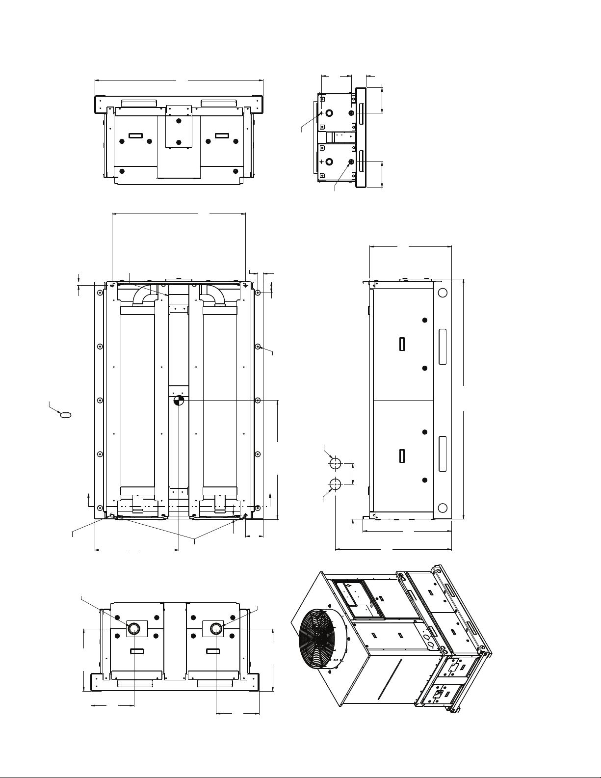
Fig. 18 — Accessory Storage Tank 30RA-900-050 Dimensions — 30RAP010-016 Units
2 X 1" [25]
a30-5429
TANK
ACCESS
TANK
ACCESS
.88" [22.35]Ø KNOCKOUT
FOR POWER TO CONTROL BOX
[1193]
3' 10-63/64"
C.B.
ACCESS
BOX END
CONTROL
TANK
ACCESS
2 X 3' 1-1/4" [946]
CHILLER MOUNTING SLOT
1-1/2"
[38.1]
3" [76.2]
MOUNTING HOLES,
FOUR CORNERS (TYP)
2 PLCS
1/4" VENT
[357.25]
2 X 14.07
2 PLCS
2" SQ DRAIN
[178.68]
2 X 7.03
[305.66]
2 X 12.03
2 PLCS
SECTION A-A
[305.64]
2 X 12.03
TANK ACCESS
[581]
1' 10-7/8"
BOX END
CONTROL
Ø7/16" [11] X 1" [25] LG SLOT
SEE DETAIL A
DETAIL A
AT (4) PLCS
A
Ø2-1/2 IN. VICTAULIC WATER
INLET/OUTLET
[442]
1' 5-13/32"
TANK
ACCESS
1' 11-1/2" [597]
CENTER OF GRAVITY
TANK
ACCESS
CHILLER MOUNTING SLOT
TANK
ACCESS
TANK
ACCESS
[27]
2 X 1-1/16"
[124]
2 X 4-7/8"
Ø2-1/2" VICTAULIC WATER
Ø .395/.405 (TYP)
MOUNTING HOLES
MIDDLE EACH SIDE
2' 9-15/32" [850]
CENTER OF GRAVITY
A
INLET/OUTLET
[442]
1' 5-13/32"
CHILLER WATER OUT (REF)
CHILLER WATER IN (REF)
[146]
5-3/4"
[248]
9-25/32"
TANK ACCESS
[823]
2' 8-13/32"
[628]
2' 47/64"
[1700]
5' 6-15/16"
[306]
1' 1/32"
[306]
1' 1/32"
26

1' 5-13/32"
[442]
1' 1/32"
[305]
TANK
ACCESS
TANK
ACCESS
TANK
ACCESS
TANK
ACCESS
1' 1/32"
[306]
1' 5-13/32"
[442]
Ø2-1/2" VICTAULIC WATER
INLET/OUTLET
SEE DETAIL A
A
1' 11-17/32" [597]
CENTER OF GRAVITY
CHILLER MOUNTING SLOT
1" [26]
2 X 4-7/8"
[124]
Ø2-1/2" VICTAULIC WATER
INLET/OUTLET
CHILLER WATER IN (REF)
1' 3-7/16" [392]
2' 8-13/32"
[823]
2' 23/32"
[628]
7' 4-31/32"
[2260]
TANK ACCESS TANK ACCESS
5-3/4"
[146]
CHILLER WATER OUT (REF)
3' 8-1/2" [1130]
CENTER OF GRAVITY
DETAIL A
AT (4) PLCS
Ø7/32" [6] X 1" [25] LG SLOT
2 X 1" [25]
Ø.88" (22.35) KNOCKOUT FOR
POWER TO THE CONTROL BOX
TANK
ACCESS
TANK
ACCESS
2 X 3' 1-1/4" [946]
CHILLER MOUNTING
SLOT
CONTROL
BOX END
TANK
ACCESS
Ø.395/.405 (TYP)
MOUNTING HOLES,
MIDDLE EACH SIDE
3" [76.2]
MOUNTING HOLES
FOUR CORNERS (TYP)
1-1/2"
[38.1]
2" SQ DRAIN
2 PLCS
TANK ACCESS
CONTROL
BOX END
1' 10-7/8"
[581]
SECTION A-A
2 PLCS
2 X 12.2
[305.24]
2 X 12.03
[305.52]
2 X 7.03
[178.68]
2 X 14.07
[357.25]
1/4" VENT
2 PLCS
3' 10-63/64"
[1193]
C.B.
ACCESS
Fig. 19 — Accessory Storage Tank 30RA-900-051 Dimensions — 30RAP018-030 Units
a30-5430
27

Fig. 20 — Accessory Storage Tank 30RA-900-052 Dimensions — 30RAP035-060 Units
1' [305]
1' 5-13/32"
[442]
TAN K
ACCESS
TAN K
ACCESS
TAN K
ACCESS
1' 1/16"
[306]
1' 5-13/32"
[442]
CHILLER MOUNTING SLOT
Ø2-1/2" VICTAULIC WATER
INLET/OUTLET
DETAIL A
AT (4) PLCS
Ø7/32" [6] X 1" [25] LG SLOT
SEE DETAIL A
1-1/2"
[38.1]
3" [76.2]
MOUNTING HOLES,
FOUR CORNERS (TYP)
A
4' 1-3/8" [1254]
CENTER OF GRAVITY
3' 7-31/32"
[111 7]
MOUNTING HOLES
3' 7-31/32"
[111 7]
A
3' 8-1/2" [1130]
CENTER OF GRAVITY
3' 8-3/32" [1120]
4' 6-5/8"
[1387]
2' 10-3/32"
[866]
2' 47/64"
[628]
TAN K
ACCESS
TAN K
ACCESS
TAN K
ACCESS
CONTROL
BOX END
1' 10-7/8"
[581]
7' 4-31/32"
[2260]
CHILLER WATER OUT
FAR SIDE (REF)
2 X 12.02
[305.23]
2 X 22.94
[582.56]
2" SQ DRAIN
4 PLCS
CHILLER WATER IN
FAR SIDE (REG)
2 X 0' -1 1/6"
2 X 0' -4 7/8"
2 X 28.84
[732.43]
SECTION A-A
2 PLCS
CONTROL
BOX END
MOUNTING HOLES
Ø.88" (22.35) KNOCKOUT FOR
POWER TO THE CONTROL BOX
2 X 7' 5" [2260]
CHILLER MOUNTING SLOT
TAN K
ACCESS
CONTROL
BOX END
Ø.88" (22.35) KNOCKOUT FOR
POWER TO THE CONTROL BOX
TAN K
ACCESS
Ø.395/.405 (TYP)
MOUNTING HOLES,
MIDDLE EACH SIDE
TANK
ACCESS
8' 2-3/4"
[2508]
1/4" VENT
4 PLCS
2 X 22.90
[581.65]
2 X 12.06
[306.43]
4 X 14.07
[357.25]
4 X 7.03
[178.68]
TANK
ACCESS
TANK
ACCESS
TANK
ACCESS
C.B.
ACCESS
C.B.
ACCESS
a30-5431
28
Dual Chiller Control Option — If the dual chiller algorithm is
A
B
1/4 N.P.T.
0.505/0.495
0.61
DIA
6” MINIMUM
CLEARANCE FOR
THERMISTOR
REMOVAL
Fig. 21 — Dual Leaving Water Thermistor Well
PART
NUMBER
DIMENSIONS in. (mm)
A B
10HB50106801 3.10 (78.7) 1.55 (39.4)
10HB50106802 4.10 (104.1) 1.28 (32.5)
Fig. 22 — Dual Chiller Piping Diagram
Depending on piping sizes, use either:
• HH79NZ014 sensor/10HB50106801 (3-in. sensor/well)
• HH79NZ029 sensor/10HB50106802 (4-in. sensor/well)
NOTE: This is a simplified piping diagram—not all hydronic specialties are shown.
Pump and Check Valve
or Isolation Valve
Pump and Check Valve
or Isolation Valve
Dual Chiller
LWT Sensor
and Well
Control
Box
Cooler
Master Chiller
Slave Chiller
Control
Box
Cooler
CCN Bus
LEGEND
LWT —
Leaving Water (Fluid) Temperature
—
Field Wiring
—
Field Communication Wiring
utilized the machines must be installed in parallel. An additional chilled water sensor must be installed. Install
the well in the
common leaving water header. See Fig. 21 and 22.
Parallel chiller control with dedicated
pumps is recommended. Chiller must start and stop its own water pump located in its own piping. If pumps are not dedicated for each
chiller, then isolation valves are required. Each chiller m
ust
open and close its own isolation valve through the unit control
(the valve must be connected to the pump outputs). See Fig. 22.
Do not relocate the chiller’s leaving water thermistors. They
must
remain in place for the unit to operate properly. The
thermistor well is a
1
/4-in. NPT fitting for mounting the well in
the piping. Select a location that will allow for removal of the
thermistor without any restrictions. Once the well is installed,
insert the thermistor into the well utilizing thermal conductive
grease. Once the thermistor is in place, it is recommended that
a thermistor wire loop be made and secured with a wire tie to
the well. Attach the dual leaving water temperature thermistor
to LVT-22 and 23. A Carrier Comfort Network® (CCN) bus
must be connected between the two chillers. For more information regarding Communication Bus Wiring, see the Carrier
Comfort Network®
(CCN) Interface section of the Controls,
Start-Up, Operation, Service, and Troubleshooting guide.
29
VICTAULIC COUPLING INSTALLATION
1. The outside surface of the pipe, between the groove and
the pipe end, must be smooth and free from indentations,
projections (including weld seams), and roll marks to en
sure a leak-tight seal. All oil, grease, loose paint, and dirt
must be removed.
2. Apply a thin coat of Victaulic lubricant or silicone lubricant to the gasket sealing lips and exterior.
CAUTION
Always use a compatible lubricant to prevent the gasket
from pinching or tearing during installation. Failure to fol
low this instruction could result in joint leakage.
3. Position the gasket over the pipe end. Make sure the gasket does not overhang the pipe end.
4. Align and bring the two pipe ends together. Slide the gasket into position and center it between the groove in each
pipe end. Make sure no portion of the gasket extends into
the groove in either pipe end.
5. Install the housings over the gasket.
NOTE: Make sure the housings’ keys engage the
grooves completely on both pipe ends.
-
CAUTION
Make sure the gasket does not become rolled or pinched
while installing the housings. Failure to follow this instruc
tion could cause damage to the gasket, resulting in joint
leakage.
6. Install the bolts, and thread a nut finger-tight onto each
bolt. For couplings supplied with stainless steel hardware,
apply an anti-seize compound to the bolt threads. Make
sure the oval neck of each bolt seats properly in the bolt
hole.
7. Tighten the nuts evenly by alternating sides until metalto-metal contact occurs at the bolt pads. Make sure the
housings’ keys engage the grooves completely.
NOTE: It is important to tighten the nuts evenly to prevent gasket pinching.
8. Visually inspect the bolt pads at each joint to ensure metal-to-metal contact is achieved.
UNITS WITH FACTORY-INSTALLED HYDRONIC
PACKAGES —
hydronic packages are designed for use with closed sys
tems, meaning that there is no more than one water-air interface in the water loop. Cooling tower loops, for example,
have two water-air interfaces (sump and nozzles) and would
thus be classified as open, whereas a correctly designed
chilled water loop with the only water-air interface being in
the expansion tank is closed. Since closed and open water
The 30RAP chillers with factory-installed
-
systems behave very differently, these instructions assume
that the chilled water loop is closed. A system installed in
correctly such that air is not handled properly — pipe leaks,
-
-
vent leaks, air in pipes, etc. — may behave as an open sys
tem and thus have unsatisfactory operation. Pump seal wear
can also cause leaks that cause poor system operation.
Proper closed system design and installation procedures
should be followed closely. The system must be constructed
with pressure-tight components and thoroughly tested for
installation leaks. Factory-supplied hydronic systems are avail
able with single or dual (for back-up) pumps.
Figure 23 shows a typical installation with components that
might be installed with the hydronic package of the 30RAP
unit. The factory-installed system includes all of the compo
nents within the dashed lines. Figure 24 illustrates a typical
dual pump package for the 010-030 size models.
NOTE: For units with single pumps, it is recommended that
isolation (shutoff) valves be placed exterior to the unit to
allow removal and service of the entire pump assembly, if
necessary. Units with dual pumps have pump isolation
valves provided. Also, if the unit is isolated with valves, a
properly sized pressure relief valve should be installed in
the piping between the unit and the valves, following all
applicable state and local codes.
System Pressurization — A proper initial cold fill pressure
must be established before the filling of the unit. The initial
cold fill pressure is the pressure applied at the filling point to
fill a system to its highest point, plus a minimum pressure at the
top of the system (4 psi [28 kPa] minimum) to operate air vents
and positively pressurize the system.
The compression tank (sometimes called expansion tank) is
very important to system pressurization. The compression tank
actually serves several purposes:
1. Provides net positive suction head required (NPSHR) for
the pump to operate satisfactorily.
2. Sets system pressure.
3. Accommodates expansion/contraction of water due to
temperature changes.
4. Acts as a pressure reference for the pump.
The compression tank pressure must be set BEFORE the
system is filled. Expansion tanks are factory supplied on sizes
010-060 only and field supplied on all other sizes. The tanks
are pre-charged at the factory to 40 psig (276 kPa). If the
30RAP unit with expansion tank is the high point in the sys
tem, tank pre-charge pressure of 40 psig (276 kPa) will be adequate. If the 30RAP unit with expansion tank is NOT at the
high point in the system, then the minimum pre-charge pres
sure for the water system must be determined using Table 6
and the method below:
Tank Pressure = 4 + (height from tank to top of
system in feet/“X”)
[27.6 + (height in m x 22.6/“X”)]
-
-
-
-
-
-
30
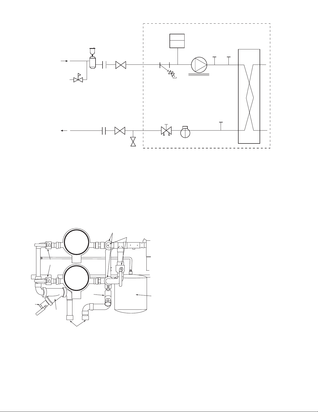
8
9
10
12
11
14
12
11
13
2
1
3
4
5
6
7
6
LEGEND
1—
Strainer/Blow-Down Valve
2—
Expansion Tank (010-060 sizes only)
3—
Pump
4—
Electric Heater
5—
Air Vent Connection Port
6—
Pressure/Temperature Access Port
7—
Heat Exchanger
8—
Flow Switch
9—
Balance Valve/Drain Plug
10 —
Pressure Relief
11 —
Isolation Valves
12 —
Flex Connections
13 —
Pressure Reducing/Fill Valve
14 —
Air Separator and Vent
---
Factory Supplied
a30-4871
Fig. 23 — Typical Piping Diagram — 30RAP Units with Hydronic Package
LEGEND
1—Strainer
2—Blow-Down Valve
3—Service Valves
4—Discharge Check Valve
(Dual Pumps Only)
5—Expansion Tank
6
— Balancing Valve with
Drain Plug
7—Field Connections
Fig. 24 — Typical Dual Pump Package
(010-030 sizes only)
4
3
3
2
1
7
6
31
5

For example, assuming a system containing a 20% concentration of ethylene glycol and 50 ft (15.2 m) in height from the
top of the system to the expansion tank, the minimum tank precharge pressure would be:
Tank Pressure = 4 + (50 / 2.38) = 25.0 psig
= 27.6 + (15.2 x 22.6 / 2.38) = 171.9 kPa
Table 6 — “X” Factor for Setting Tank Pressure
% GLYCOL
0 (pure water) 2.31 2.31
10 2.36 2.33
20 2.38 2.36
30 2.40 2.38
40 2.43 2.38
50 2.47 2.40
NOTE: If expansion tanks are placed elsewhere in the system this
method cannot be used since extra pressure drop between the tank
and the pump must be accounted for.
ETHYLENE
GLYCOL
PROPYLENE
GLYCOL
NOTE: If the system requires a pre-charge greater than
40 psig (276 kPa), increase pressure as described below.
Expansion Tank Pre-Charge — To pre-charge the expansion
tank, do the following steps:
1. Check the tank air pressure at the pre-charge connection
with an accurate pressure gage. Adjust as needed.
2. If additional pressure is required, charge the tank with oilfree compressed air or nitrogen gas. Occasionally check
the pressure as when filling a tire.
3. Check the air valve for leakage. If it leaks, relieve the
pressure and replace the core with a Schrader type tire
core. DO NOT depend on the valve cap to seal the leak.
Once the system is pressurized, the pressure at the connection point of the expansion tank to water piping will not change
unless the water loop volume changes (either due to addition/
subtraction of water or temperature expansion/contraction).
The pressure at this point remains the same regardless of
whether or not the pump is running.
Since the expansion tank acts as a reference point for the
pump, there cannot be two reference points (two expansion
tanks) in a system (unless manifolded together). If system
volume or other design considerations warrant the placement
of another expansion tank somewhere in the system, the expan
sion tank in the 30RAP hydronic package MUST be disconnected from its hose and the end of the hose securely plugged.
This is also true for applications where two or more 30RAP
chillers are placed in parallel. There should not be more than
one expansion tank in the system (as seen in Fig.
24) unless
manifolded together. When multiple 30RAP chillers are applied in parallel, and the chillers include the optional hydronic
package which contain expansion tanks (sizes 010-060), the
expansion tanks must be disconnected from the 30RAP hy
dronic package. It is permissible to install the expansion tank(s)
in a portion of the return water line that is common to all
pumps, providing that the tank is properly sized for combined
system volume.
If the application involves two or more chillers in a primary/
secondary system, a common place for mounting the
expansion tank is in the chilled water return line, just before the
decoupler. See Fig.
25 for placement of expansion tank in
primary/secondary systems.
The expansion tank included in the 30RAP hydronic package is a diaphragm tank, meaning that a flexible diaphragm
physically separates the water/air interface. With this type of
expansion tank, it is undesirable to have any air in the water
loop. See the section on air separation below for instructions on
providing air separation equipment.
AIR SEPARATION — For proper system operation, it is
essential that water loops be installed with proper means to
manage air in the system. Free air in the system can cause
noise, reduce terminal output, stop flow, or even cause pump
failure due to pump cavitation. For closed systems, equipment
should be provided to eliminate all air from the system.
The amount of air that water can hold in solution depends
on the pressure and temperature of the water/air mixture. Air is
less soluble at higher temperatures and at lower pressures.
Therefore, separation can best be done at the point of highest
water temperature and lowest pressure. Typically, this point
would be on the suction side of the pump as the water is return
ing from the system or terminals. Generally speaking, this is
the best place to install an air separator, if possible.
1. Install automatic air vents at all high points in the system.
(If the 30RAP unit is located at the high point of the
system, a vent can be installed on the piping entering the
heat exchanger on the ¼-in. NPT female port.)
2. Install an air separator in the water loop, at the place
where the water is at higher temperatures and lower
pressures — usually in the chilled water return piping.
On a primary-secondary system, the highest temperature
water is normally in the secondary loop, close to the
decoupler. Preference should be given to that point on the
system (see Fig.
24). In-line or centrifugal air separators
are readily available in the field.
It may not be possible to install air separators at the place of
lowest pressure and highest temperature. In such cases, preference should be given to the points of highest temperature. It is
-
important that pipe be sized correctly so that free air can be
moved to the point of separation. Generally, a water velocity of
at least 2 ft (610 mm) per second will keep free air entrained
and prevent it from forming air pockets.
Automatic vents should be installed at all physically elevated points in the system so that air can be eliminated during
system operation. Provision should also be made for manual
venting during the water loop fill. It is important that the
automatic vents be located in accessible locations for
-
maintenance purposes, and that they be located where they can
be prevented from freezing.
32

Distribution Pump
Expansion
Tank(s)
Air Separator
with Vent
Decoupler
Chiller 1
Chiller 2
Zone 1
Zone 2
Zone 3
NOTE: Expansion tanks in the 30RAP hydronic kits must be disconnected for chillers placed parallel in the primary water loop.
Fig. 25 — Typical Air Separator and Expansion Tank Location on Primary-Secondary Systems
Step 4 — Fill the Chilled Water Loop
WATER SYSTEM CLEANING — Proper water system
cleaning is of vital importance. Excessive particulates in the
water system can cause excessive pump seal wear, reduce or
stop flow, and cause damage of other components. Water
quality should be maintained within the limits indicated in
Table 7. Failure to maintain proper water quality may result in
heat exchanger failure.
CAUTION
Failure to properly clean all piping and components of the
chilled water system before unit start-up may result in
plugging of the heat exchanger, which can lead to poor performance, nuisance alarms and damage from freezing.
Freezing
represents abuse and may impair or otherwise negatively
affect the Carrier product warranty.
1. Install a temporary bypass around the chiller to avoid cir-
2. Be sure to use a cleaning agent that is compatible with all
3. It is a good idea to fill the system through a water meter.
4. Use a feeder/transfer pump to mix the solution and fill the
damage caused by an improperly cleaned system
culating dirty water and particulates into the pump package and chiller during the flush. Use a temporary circulating pump during the cleaning process. Also, be sure that
ther
e is capability to fully drain the system after cleaning.
(See Fig. 26.)
materials. Be especially careful if the system
system
contains any galvanized or aluminum components. Both
detergent-dispersant and alkaline-dispersant cleaning
agents are available.
This provides a reference point
for the future for loop
volume readings, and it also establishes the correct
quantity of cleaner needed in order to get the required
concentration.
tem. Circulate the cleaning system for the length of
sys
time recommended by the cleaning agent manufacturer.
a. After cleaning, drain the cleaning fluid and flush
the
system with fresh water.
b. A slight amount of cleaning residue in the
can help keep the desired, slightly alkaline, water
pH of 8 to 9. Avoid a pH greater than 10, since this
system
will adversely affect pump seal components.
c. A side stream filter is recommended (see Fig. 27)
during the cleaning process.
Filter side flow rate
should be enough to filter the entire water volume
every 3 to 4 hours. Change filters as often as necessary during the cleaning process.
d. Remove temporary bypass when cleaning is
co
mplete.
Table 7 — Water Quality Characteristics
a
nd Limitations
WATER CHARACTERISTIC QUALITY LIMITATION
Alkalinity (HCO
Sulfate (SO
-
/SO
HCO
3
Electrical Conductivity 10 – 500S/cm
pH 7.5 – 9.0
Ammonia (NH
Chorides (Cl
Free chlorine (Cl
Hydrogen Sulfide (H
Free (aggressive) Carbon
Dioxide (CO
Total Hardness (°dH) 4.0 – 8.5
Nitrate (NO
Iron (Fe) Less than 0.2 ppm
Aluminum (Al) Less than 0.2 ppm
Manganese (Mn) Less than 0.1 ppm
*Sulfides in the water quickly oxidize when exposed to air, requiring that
no agitation occur as the sample is taken. Unless tested immediately
at the site, the sample will require stabilization with a few drops of one
Molar zinc acetate solution, allowing accurate sulfide determination up
to 24 hours after sampling. A low pH and high alkalinity cause system
problems, even when both values are within the ranges shown. The
term pH refers to the acidity, basicity, or neutrality of the water supply.
Below 7.0, the water is considered to be acidic. Above 7.0, water is
considered to be basic. Neutral water contains a pH of 7.0.
†Dissolved carbon dioxide can either be calculated from the pH and
tal alkalinity values, shown below, or measured on the site using a
to
test kit. Dissolved Carbon Dioxide, PPM = TA x 2
= Total Alkalinity, PPM as CaCO
-
) 70 – 300 ppm
3
2-
) Less than 70 ppm
4
2-
4
) Less than 2 ppm
3
-
) Less than 300 ppm
) Less than 1 ppm
2
S)* Less than 0.05 ppm
2
)†
2
) Less than 100 ppm
3
Greater than 1.0
Less than 5 ppm
.
3
[(6.3-pH)/0.3]
where TA
A 40-mesh strainer with a blow-down valve is standard on
all 30RAP units, both with and without hydronic packages.
The blow-down valve allows removal of particulates caught in
the strainer without complete removal of the screen. A female
NPT connection is provided on the valve, allowing hose connection for drainage outside the unit.
Carrier’s Comf
ortLink controls have a built-in feature to
remind building owners or operators to clean the strainer by
discharging the blow-down valve at a pre-set time interval.
Properly installed and cleaned systems will rarely need the
strainer cleaned after the initial fill. This time interval is
user-configurable.
33

SYSTEM
Fig. 26 — Typical Set Up for Cleaning Process
a30-5289
x
x
DILUTED
CLEANING
AGENT
SYSTEM
SIDE
STREAM
FILTER
POT FEEDER AND
TRANSFER PUMP
30RAP UNIT
TO DRAIN
TEMPORARY
PUMP
TEMPORARY
BYPASS
Fig. 27 — Cleaning Using a Side Stream Filter
a30-5290
POT FEEDER AND
DILUTED
CLEANING
AGENT
TRANSFER PUMP
TEMPORARY
PUMP
TO DRAIN
x
x
TEMPORARY
BYPASS
FILLING THE SYSTEM — The initial fill of the chilled
water system must accomplish three purposes:
1. The entire piping system must be filled with water.
2. The pressure at the top of the system must be high enough
to vent air from the system (usually 4 psig [28 kPa] is adequate for most vents).
3. The pressure at all points in the system must be high
enough to prevent flashing in the piping or cavitation in
the pump.
The pressure created by an operating pump affects system
pressure at all points except one — the connection of the
compression tank to the system. This is the only location in the
system where pump operation will not give erroneous pressure
indications during the fill. Therefore, the best location to install
the fill connection is close to the expansion tank. An air vent
should be installed close by to help eliminate air that enters
during the fill procedure.
Ensure the following when filling the system:
1. Remove temporary bypass piping and cleaning/flushing
equipment.
2. Check to make sure all drain plugs are installed.
3. Open the blow-down valve to flush the strainer.
Normally, a closed system needs to be filled only once. The
actual filling process is generally a fairly simple procedure. All
air should be purged or vented from the system. Thorough
venting at the high points and circulation at room temperature
for several hours is recommended.
30RAP UNIT
NOTE: Local codes concerning backflow devices and other
protection of the city water system should be consulted and
followed to prevent contamination of the public water
supply. This is especially important when antifreeze is used
in the system.
Set Water Flow Rate — Once the system is cleaned, pressurized, and filled, the flow rate through the chiller must be established. On units with the hydronic package, this can best be
done using the balancing valve.
In order to adjust the balancing valve, put a differential
pressure gage across the pressure taps on the valve. Make sure
that all system isolation and control valves are open. Use Ta
-
bles 8-11 to determine gpm.
1. Measure the pressure drop across the balancing valve. If
the pressure reading is in psig, multiply psig by 2.31 to
convert to feet of water before using Tables
8-12.
2. Go to the row in the chart corresponding to the setting on
the valve, interpolating if necessary.
3. The gpm corresponding to the pressure drop measured is
the flow through the balancing valve.
NOTE: Carrier recommends a differential pressure gage when
measuring pressures across the pumps or balancing valves.
This provides for greater accuracy and reduces error build-up
that often occurs when subtracting pressures made by different
gages.
On primary/secondary systems, it is advisable to set the
30RAP balancing valve to maintain design flow plus 10%
through the chiller.
A rough estimate of water flow can also be obtained from
the pressure gages across the 30RAP heat exchanger.
Figures
28-35 show the relationship between gpm and heat exchanger pressure drop. It should be noted that these curves are
for “clean” heat exchangers; they do not apply to heat exchang
ers with fouling. To read the chart, subtract the readings of the
two pressure gages on the hydronic kit. This number is the
pressure drop across the heat exchanger. Adjust the factoryinstalled balancing valve or external balancing valve (units
without hydronic package) until the correct pressure drop is ob
tained for the required gpm. Total unit pressure drop is found in
Appendix A.
Water Treatment — Fill the fluid loop with water (or suitable
inhibited antifreeze solution) and a corrosion-resistant inhibitor
suitable for the water of the area. Consult the local water treat
ment specialist for characteristics of system water and a recommended inhibitor for the cooler fluid loop.
Untreated or improperly treated water may result in corrosion, scaling, erosion, or algae. The services of a qualified water treatment specialist should be obtained to develop and monitor a treatment program.
CAUTION
Water must be within design flow limits, clean, and treated
to ensure proper chiller performance and reduce the poten
tial of tube damage due to corrosion, scaling, erosion, and
algae. Carrier assumes no responsibility for chiller damage
resulting from untreated or improperly treated water.
-
34

Table 8 — Balancing Valve Readings — 30RAP010-030
2.0 in.
SETTING
0.5 8.3 0.8 3.4 7.5 13.4 21.0 30.2 41.1 53.7 67.9 83.8
1.0 10.2 0.6 2.2 5.0 8.9 13.9 20.0 27.2 35.5 45.0 55.5
1.5 13.0 0.3 1.4 3.1 5.5 8.5 12.3 16.7 21.9 27.7 34.2
2.0 16.9 0.2 0.8 1.8 3.2 5.1 7.3 9.9 12.9 16.4 20.2
2.5 20.5 0.1 0.5 1.2 2.2 3.4 4.9 6.7 8.8 11.1 13.7
3.0 25.9 0.1 0.3 0.8 1.4 2.2 3.1 4.2 5.5 7.0 8.6
3.5 29.0 0.1 0.3 0.6 1.1 1.7 2.5 3.4 4.4 5.6 6.9
4.0 35.8 0.0 0.2 0.4 0.7 1.1 1.6 2.2 2.9 3.6 4.5
5.0 37.0 0.0 0.2 0.4 0.7 1.1 1.5 2.1 2.7 3.4 4.2
VALVE
COEFFICIENT
(C
)
v
5 101520253035404550
WATER PRESSURE DROP (ft)
GPM
2.0 in.
SETTING
0.5 8.3 101.4 120.7 141.7 164.3 188.6 214.6 242.3 271.6 302.6 335.3
1.0 10.2 67.2 79.9 93.8 108.8 124.9 142.1 160.4 179.8 200.4 222.0
1.5 13.0 41.3 49.2 57.8 67.0 76.9 87.5 98.8 110.7 123.4 136.7
2.0 16.9 24.5 29.1 34.2 39.6 45.5 51.8 58.4 65.5 73.0 80.9
2.5 20.5 16.6 19.8 23.2 26.9 30.9 35.2 39.7 44.5 49.6 55.0
3.0 25.9 10.4 12.4 14.5 16.9 19.4 22.0 24.9 27.9 31.1 34.4
3.5 29.0 8.3 9.9 11.6 13.5 15.5 17.6 19.8 22.2 24.8 27.5
4.0 35.8 5.5 6.5 7.6 8.8 10.1 11.5 13.0 14.6 16.3 18.0
5.0 37.0 5.1 6.1 7.1 8.3 9.5 10.8 12.2 13.7 15.2 16.9
VALVE
COEFFICIENT
(C
)
v
55 60 65 70 75 80 85 90 95 100
WATER PRESSURE DROP (ft)
GPM
NOTE: See Table 12 for Glycol Correction Factors.
Table 9 — Balancing Valve Readings — 30RAP035-060
2.5 in.
SETTING
1.0 15.6 15.2 19.2 23.7 28.7 34.2 40.1 46.5 53.4 60.7 68.6 76.9
2.0 21.1 8.3 10.5 13.0 15.7 18.7 21.9 25.4 29.2 33.2 37.5 42.0
3.0 24.5 6.2 7.8 9.6 11.6 13.9 16.3 18.9 21.6 24.6 27.8 31.2
4.0 38.0 2.6 3.2 4.0 4.8 5.8 6.8 7.8 9.0 10.2 11.6 13.0
4.5 52.0 1.4 1.7 2.1 2.6 3.1 3.6 4.2 4.8 5.5 6.2 6.9
5.0 69.0 0.8 1.0 1.2 1.5 1.7 2.0 2.4 2.7 3.1 3.5 3.9
2.5 in.
SETTING
1.0 15.6 85.7 94.9 104.7 114.9 125.5 136.7 148.3 160.4 173.0 186.0 199.6
2.0 21.1 46.8 51.9 57.2 62.8 68.6 74.7 81.1 87.7 94.6 101.7 109.1
3.0 24.5 34.7 38.5 42.4 46.6 50.9 55.4 60.1 65.0 70.1 75.4 80.9
4.0 38.0 14.4 16.0 17.6 19.4 21.2 23.0 25.0 27.0 29.2 31.4 33.6
4.5 52.0 7.7 8.5 9.4 10.3 11.3 12.3 13.3 14.4 15.6 16.7 18.0
5.0 69.0 4.4 4.9 5.3 5.9 6.4 7.0 7.6 8.2 8.8 9.5 10.2
VALVE
COEFFICIENT
(C
)
v
VALVE
COEFFICIENT
(C
)
v
40 45 50 55 60 65 70 75 80 85 90
95 100 105 110 115 120 125 130 135 140 145
WATER PRESSURE DROP (ft)
GPM
WATER PRESSURE DROP (ft)
GPM
2.5 in.
SETTING
1.0 15.6 213.6 228.0 243.0 258.4 274.3 290.7 307.5 324.9 342.7 360.9 379.7
2.0 21.1 116.7 124.7 132.8 141.3 149.9 158.9 168.1 177.6 187.3 197.3 207.5
3.0 24.5 86.6 92.5 98.5 104.8 111.2 117.9 124.7 131.7 138.9 146.3 153.9
4.0 38.0 36.0 38.4 41.0 43.6 46.2 49.0 51.8 54.8 57.8 60.8 64.0
4.5 52.0 19.2 20.5 21.9 23.3 24.7 26.2 27.7 29.2 30.8 32.5 34.2
5.0 69.0 10.9 11.7 12.4 13.2 14.0 14.9 15.7 16.6 17.5 18.4 19.4
VALVE
COEFFICIENT
(C
)
v
150 155 160 165 170 175 180 185 190 195 200
WATER PRESSURE DROP (ft)
GPM
NOTE: See Table 12 for Glycol Correction Factors.
35
Table 10 — Balancing Valve Readings — 30RAP070-090
3.0 in.
STRAIGHT
SETTING
1.0 20.0 28.3 37.0 46.8 57.8 69.9 83.2 97.6 113.2 129.9 147.8 166.9 187.1 208.5
1.5 22.9 21.6 28.2 35.7 44.0 53.3 63.4 74.4 86.3 99.1 112.8 127.3 142.7 159.0
2.0 25.6 17.3 22.6 28.6 35.2 42.6 50.8 59.6 69.1 79.3 90.2 101.9 114.2 127.2
2.5 27.0 15.5 20.3 25.7 31.7 38.3 45.6 53.6 62.1 71.3 81.1 91.6 102.7 114.4
3.0 30.0 12.6 16.4 20.8 25.7 31.1 37.0 43.4 50.3 57.8 65.7 74.2 83.2 92.7
3.5 36.5 8.5 11.1 14.0 17.3 21.0 25.0 29.3 34.0 39.0 44.4 50.1 56.2 62.6
4.0 56.0 3.6 4.7 6.0 7.4 8.9 10.6 12.4 14.4 16.6 18.9 21.3 23.9 26.6
4.5 76.0 2.0 2.6 3.2 4.0 4.8 5.8 6.8 7.8 9.0 10.2 11.6 13.0 14.4
5.0 94.5 1.3 1.7 2.1 2.6 3.1 3.7 4.4 5.1 5.8 6.6 7.5 8.4 9.3
VALVE
COEFFICIENT
(C
)
v
70 80 90 100 110 120 130 140 150 160 170 180 190
WATER PRESSURE DROP (ft)
GPM
3.0 in.
STRAIGHT
SETTING
1.0 20.0 231.0 254.7 279.5 305.5 332.6 360.9 390.4 421.0 452.8 485.7 519.8 555.0 591.4
1.5 22.9 176.2 194.3 213.2 233.0 253.7 275.3 297.8 321.1 345.3 370.5 396.4 423.3 451.1
2.0 25.6 141.0 155.4 170.6 186.5 203.0 220.3 238.3 257.0 276.3 296.4 317.2 338.7 360.9
2.5 27.0 126.7 139.7 153.4 167.6 182.5 198.0 214.2 231.0 248.4 266.5 285.2 304.5 324.5
3.0 30.0 102.7 113.2 124.2 135.8 147.8 160.4 173.5 187.1 201.2 215.9 231.0 246.7 262.8
3.5 36.5 69.4 76.5 83.9 91.7 99.9 108.4 117.2 126.4 135.9 145.8 156.1 166.6 177.6
4.0 56.0 29.5 32.5 35.7 39.0 42.4 46.0 49.8 53.7 57.8 61.9 66.3 70.8 75.4
4.5 76.0 16.0 17.6 19.4 21.2 23.0 25.0 27.0 29.2 31.4 33.6 36.0 38.4 41.0
5.0 94.5 10.3 11.4 12.5 13.7 14.9 16.2 17.5 18.9 20.3 21.8 23.3 24.9 26.5
3.0 in.
STRAIGHT
SETTING
1.0 20.0 628.9 667.6 707.4 748.4 790.6 833.9 878.4 924.0 970.8 1018.7 1067.8 1118.0 1169.4
1.5 22.9 479.7 509.2 539.6 570.9 603.0 636.1 670.0 704.8 740.5 777.0 814.5 852.8 892.0
2.0 25.6 383.8 407.5 431.8 456.8 482.5 509.0 536.1 564.0 592.5 621.8 651.7 682.4 713.8
2.5 27.0 345.1 366.3 388.2 410.7 433.8 457.6 482.0 507.0 532.7 559.0 585.9 613.5 641.7
3.0 30.0 279.5 296.7 314.4 332.6 351.4 370.6 390.4 410.7 431.5 452.8 474.6 496.9 519.8
3.5 36.5 188.8 200.4 212.4 224.7 237.4 250.4 263.7 277.4 291.5 305.9 320.6 335.7 351.1
4.0 56.0 80.2 85.2 90.2 95.5 100.8 106.4 112.0 117.9 123.8 129.9 136.2 142.6 149.2
4.5 76.0 43.6 46.2 49.0 51.8 54.8 57.8 60.8 64.0 67.2 70.5 73.9 77.4 81.0
5.0 94.5 28.2 29.9 31.7 33.5 35.4 37.4 39.3 41.4 43.5 45.6 47.8 50.1 52.4
VALVE
COEFFICIENT
(C
)
v
VALVE
COEFFICIENT
(C
)
v
200 210 220 230 240 250 260 270 280 290 300 310 320
330 340 350 360 370 380 390 400 410 420 430 440 450
WATER PRESSURE DROP (ft)
GPM
WATER PRESSURE DROP (ft)
GPM
NOTE: See Table 12 for Glycol Correction Factors.
36

Table 11 — Balancing Valve Readings — 30RAP100-150
4.0 in.
STRAIGHT
SETTING
1.0 21.5 32.0 40.5 50.0 60.5 72.0 84.5 97.9 112.4 127.9 144.4 161.9 180.4 199.9
1.5 25.0 23.7 29.9 37.0 44.7 53.2 62.5 72.4 83.2 94.6 106.8 119.8 133.4 147.8
2.0 27.2 20.0 25.3 31.2 37.8 45.0 52.8 61.2 70.3 79.9 90.2 101.2 112.7 124.9
2.5 43.0 8.0 10.1 12.5 15.1 18.0 21.1 24.5 28.1 32.0 36.1 40.5 45.1 50.0
3.0 68.0 3.2 4.0 5.0 6.0 7.2 8.4 9.8 11.2 12.8 14.4 16.2 18.0 20.0
3.5 100.0 1.5 1.9 2.3 2.8 3.3 3.9 4.5 5.2 5.9 6.7 7.5 8.3 9.2
4.0 129.0 0.9 1.1 1.4 1.7 2.0 2.3 2.7 3.1 3.6 4.0 4.5 5.0 5.6
4.5 162.0 0.6 0.7 0.9 1.1 1.3 1.5 1.7 2.0 2.3 2.5 2.9 3.2 3.5
5.0 190.0 0.4 0.5 0.6 0.8 0.9 1.1 1.3 1.4 1.6 1.8 2.1 2.3 2.6
5.5 216.0 0.3 0.4 0.5 0.6 0.7 0.8 1.0 1.1 1.3 1.4 1.6 1.8 2.0
6.0 249.0 0.2 0.3 0.4 0.5 0.5 0.6 0.7 0.8 1.0 1.1 1.2 1.3 1.5
VALVE
COEFFICIENT
(C
)
v
80 90 100 110 120 130 140 150 160 170 180 190 200
WATER PRESSURE DROP (ft)
GPM
4.0 in.
STRAIGHT
SETTING
1.0 21.5 220.4 241.9 264.4 287.8 312.3 337.8 364.3 391.8 420.3 449.8 480.2 511.7 544.2
1.5 25.0 163.0 178.9 195.5 212.9 231.0 249.8 269.4 289.8 310.8 332.6 355.2 378.5 402.5
2.0 27.2 137.7 151.1 165.2 179.8 195.1 211.1 227.6 244.8 262.6 281.0 300.1 319.7 340.0
2.5 43.0 55.1 60.5 66.1 72.0 78.1 84.5 91.1 97.9 105.1 112.4 120.1 127.9 136.1
3.0 68.0 22.0 24.2 26.4 28.8 31.2 33.8 36.4 39.2 42.0 45.0 48.0 51.2 54.4
3.5 100.0 10.2 11.2 12.2 13.3 14.4 15.6 16.8 18.1 19.4 20.8 22.2 23.7 25.2
4.0 129.0 6.1 6.7 7.3 8.0 8.7 9.4 10.1 10.9 11.7 12.5 13.3 14.2 15.1
4.5 162.0 3.9 4.3 4.7 5.1 5.5 6.0 6.4 6.9 7.4 7.9 8.5 9.0 9.6
5.0 190.0 2.8 3.1 3.4 3.7 4.0 4.3 4.7 5.0 5.4 5.8 6.1 6.6 7.0
5.5 216.0 2.2 2.4 2.6 2.9 3.1 3.3 3.6 3.9 4.2 4.5 4.8 5.1 5.4
6.0 249.0 1.6 1.8 2.0 2.1 2.3 2.5 2.7 2.9 3.1 3.4 3.6 3.8 4.1
4.0 in.
STRAIGHT
SETTING
1.0 21.5 577.7 612.2 647.6 684.1 721.6 760.1 799.6 840.0 881.5 924.0 967.5 1012.0
1.5 25.0 427.3 452.8 479.0 506.0 533.7 562.2 591.4 621.3 652.0 683.4 715.5 748.4
2.0 27.2 360.9 382.5 404.6 427.4 450.9 474.9 499.6 524.9 550.8 577.3 604.5 632.3
2.5 43.0 144.4 153.0 161.9 171.0 180.4 190.0 199.9 210.0 220.4 231.0 241.9 253.0
3.0 68.0 57.8 61.2 64.7 68.4 72.1 76.0 79.9 84.0 88.1 92.4 96.7 101.2
3.5 100.0 26.7 28.3 29.9 31.6 33.4 35.1 37.0 38.8 40.7 42.7 44.7 46.8
4.0 129.0 16.0 17.0 18.0 19.0 20.0 21.1 22.2 23.3 24.5 25.7 26.9 28.1
4.5 162.0 10.2 10.8 11.4 12.0 12.7 13.4 14.1 14.8 15.5 16.3 17.0 17.8
5.0 190.0 7.4 7.8 8.3 8.8 9.2 9.7 10.2 10.8 11.3 11.8 12.4 13.0
5.5 216.0 5.7 6.1 6.4 6.8 7.1 7.5 7.9 8.3 8.7 9.2 9.6 10.0
6.0 249.0 4.3 4.6 4.8 5.1 5.4 5.7 6.0 6.3 6.6 6.9 7.2 7.5
VALVE
COEFFICIENT
(C
)
v
VALVE
COEFFICIENT
(C
)
v
210 220 230 240 250 260 270 280 290 300 310 320 330
340 350 360 370 380 390 400 410 420 430 440 450
WATER PRESSURE DROP (ft)
GPM
WATER PRESSURE DROP (ft)
GPM
NOTE: See Table 12 for Glycol Correction Factors.
CONCENTRATION
40 (4.5) 70 (21) 40 (4.5) 70 (21)
0 1.00 1.00 1.00 1.00
10 0.99 0.99 0.99 0.99
20 0.99 0.99 0.99 0.99
30 0.98 0.98 0.99 0.99
40 0.97 0.97 0.98 0.98
50 0.96 0.96 0.97 0.98
Glycol Corrections:
GPM [actual] = GPM [tested] x Correction Factor
Table 12 — Glycol Correction Factors
GLYCOL CORRECTION FACTOR
Ethylene Propylene
Water Temp — F (C)
37
Fig. 28 — Heat Exchanger Pressure Drop (Water Only) — 30RAP010-030 (English)
LEGEND
1 — 30RAP010,011 4 — 30RAP020
2 — 30RAP015 5 — 30RAP025
3 — 30RAP016,018 6 — 30RAP030
0
5
10
15
20
25
30
35
40
45
50
01020304050607080 90 100 110 120 130 140 150
WATER PRESSURE DROP (ft wg)
GPM
12
3
4
56
Fig. 29 — Heat Exchanger Pressure Drop (Water Only) — 30RAP035-060 (English)
LEGEND
7 — 30RAP035 10 — 30RAP050
8 — 30RAP040 11 — 30RAP055
9 — 30RAP045 12 — 30RAP060
0
5
10
15
20
25
30
35
40
45
50
0 50 100 150 200 250
WATER PRESSURE DROP (ft wg)
7
8
9
10
11&12
GPM
38

1
2
3
50
40
30
20
10
WATER PRESSURE DROP (ft wg)
0
100
GPM
150
200
250 300
350
60
Fig. 30 — Heat Exchanger Pressure Drop (Water Only) — 30RAP070-090 (English)
LEGEND
1 — 30RAP070
2 — 30RAP080
3 — 30RAP090
Fig. 31 — Heat Exchanger Pressure Drop (Water Only) — 30RAP100-150 (English)
0
5
10
15
20
25
30
35
40
45
50
150 200 250 300 350 400 450 500
GPM
WATER PRESSURE DROP (ft wg)
1
2
3
4
a30-5444
LEGEND
1 — 30RAP100
2 — 30RAP115
3 — 30RAP130
4 — 30RAP150
39

Fig. 32 — Heat Exchanger Pressure Drop (Water Only) — 30RAP010-030 (SI)
LEGEND
1 — 30RAP010,011 4 — 30RAP020
2 — 30RAP015 5 — 30RAP025
3 — 30RAP016,018 6 — 30RAP030
0
25
50
75
100
125
150
0123 45678 910
WATER PRESSURE DROP (kPa)
123 45 6
LITERS/SECOND
Fig. 33 — Heat Exchanger Pressure Drop (Water Only) — 30RAP035-060 (SI)
LEGEND
7 — 30RAP035 10 — 30RAP050
8 — 30RAP040 11 — 30RAP055
9 — 30RAP045 12 — 30RAP060
150
125
7 8 910
11&12
100
75
50
WATER PRESSURE DROP (kPa)
25
0
LITERS/SECOND
40
510150

Fig. 34 — Heat Exchanger Pressure Drop (Water Only) — 30RAP070-090 (SI)
40
60
80
100
120
140
160
0
20
40
0 5 10 15 20 25
LITERS/SECOND
WATER PRESSURE DROP (kPa)
1
2
3
LEGEND
1 — 30RAP070
2 — 30RAP080
3 — 30RAP090
a30-5351
Fig. 35 — Heat Exchanger Pressure Drop (Water Only) — 30RAP100-150 (SI)
0
20
40
60
80
100
5101520253035
LITERS/SECOND
WATER PRESSURE DROP (kPa)
1
2
3
4
120
140
160
LEGEND
1 — 30RAP100
2 — 30RAP115
3 — 30RAP130
4 — 30RAP150
a30-5445
41
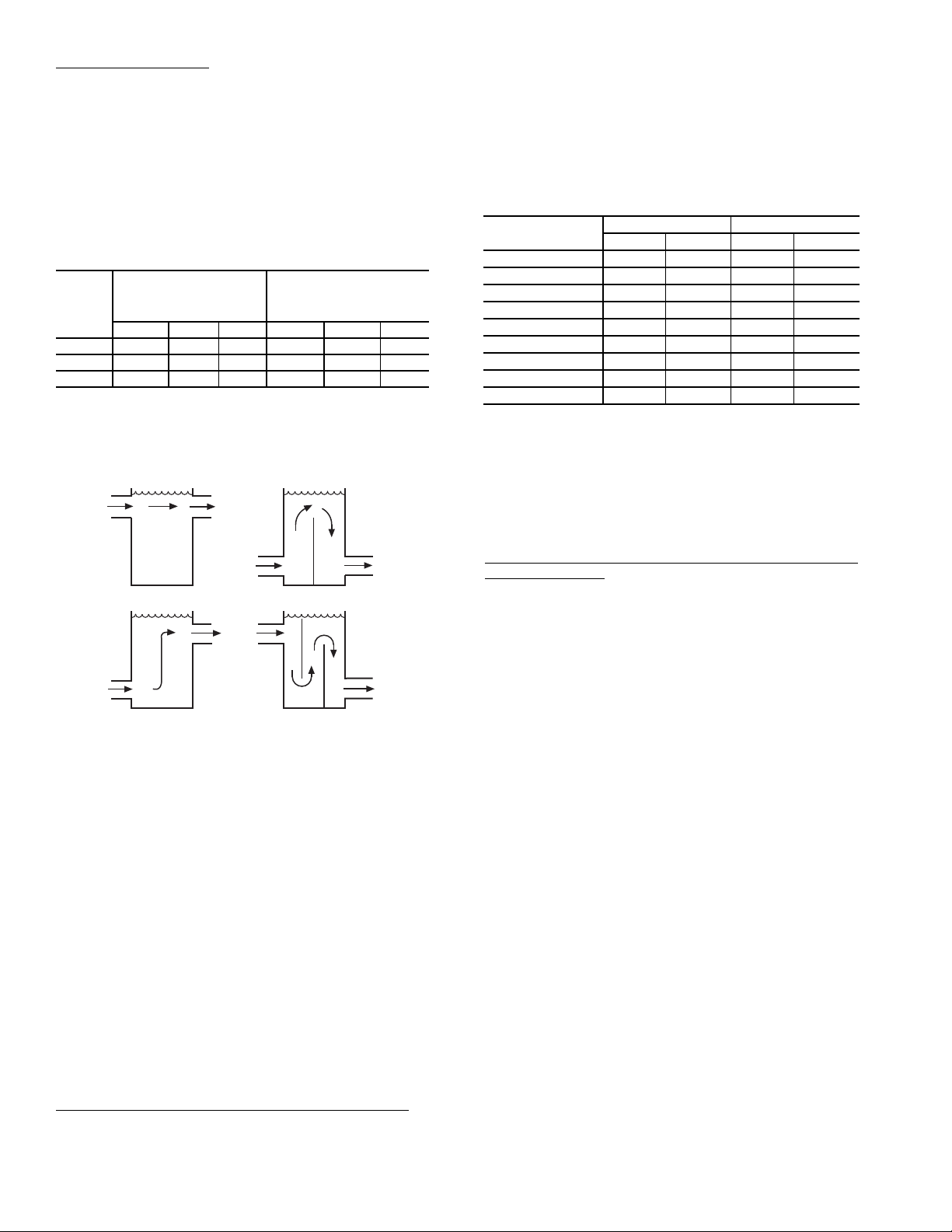
Minimum Loop Volume — The minimum volume of fluid
BAD
BAD
GOOD
GOOD
Fig. 36 — Tank Baffling
required to be in circulation is a function of the number of com
pressors in the chiller as well as the type of application. The
minimum fluid in circulation must equal or exceed the values
in Table
13.
To achieve this fluid volume, it is often necessary to install a
tank in the loop. The tank should be baffled to ensure there is
no stratification and that water (or suitable inhibited antifreeze
solution) entering the tank is adequately mixed with liquid in
the tank. See Fig.
36.
Table 13 — Minimum Fluid Volume In Circulation
NORMAL AIR
30RAP
UNIT
SIZE
010-016 12 (13.0) N/A 3 (3.3) 12 (13.0) N/A 6 (6.5)
018-030 6 (6.5) 4 (4.3) 3 (3.3) 10 (10.8) 10 (10.8) 6 (6.5)
035-150 3 (3.3) 3 (3.3) 3 (3.3) 6 (6.5) 6 (6.5) 6 (6.5)
LEGEND
HGBP —
CONDITIONING
APPLICATION
gal./ton (L per kW)
Std Unit HGBP Digital Std Unit HGBP Digital
Hot Gas Bypass
PROCESS COOLING OR
LOW AMBIENT
OPERATION APPLICATION
gal./ton (L per kW)
The limits are dependent on the maximum and minimum tem-
-
peratures of the water, the maximum and minimum pressures
seen by the expansion tank, and the heat transfer fluid. Expansion tank and maximum loop volume data is as follows:
30RAP010-030 30RAP035-060
Volume gal. (L) 5.0 (18.9) 10.0 (37.9)
Acceptance Volume gal. (L) 2.9 (11.0) 5.5 (20.8)
Table 14 — Maximum Loop Volume Limits
CONCENTRATION
PURE WATER 412 1560 1356 5131
10% EG 239 906 795 3009
20% EG 233 880 767 2902
30% EG 206 781 692 2620
40% EG 200 755 655 2478
10% PG 233 880 767 2902
20% PG 200 755 655 2478
30% PG 170 645 561 2124
40% PG 157 595 514 1947
LEGEND
EG —
PG —
NOTE: Maximum loop volume is based on typical system of 12 psig
(83 kPa) and 30 psig (207 kPa) of min/max pressures, and 100 F
(37.8 C) mean temperature. If the volume in the system is greater
than the limits listed, then extra expansion tank volume must be
added to the system.
Ethlyene Glycol
Propylene Glycol
30RAP010-030 30RAP035-060
Gal. L Gal. L
The piping between the chiller and the accessory tank can
be done to allow the tank to be on the return side of the chiller
(tank piped to chiller inlet) or the supply side of the chiller
(tank piped to the chiller outlet). For standard compressors, it is
recommended that the tank be piped to the return side of the
chiller to buffer any changes in load to allow more stable
chiller operation. For digital compressor applications, it is rec
ommended that the tank be piped to the supply side of the
chiller to provide a more stable supply temperature.
A properly baffled storage tank is available from the factory
as an accessory for sizes 010-060 only. These tanks are de
signed to physically fit beneath the corresponding 30RAP unit,
taking up the same footprint.
• 30RAP010-016 83 gallons (314 liters)
• 30RAP018-030 119 gallons (450 liters)
• 30RAP035-060 241 gallons (912 liters)
Storage tank weight (water weight included) is as follows:
• 30RAP010-016 1673 lb (759 kg)
• 30RAP018-030 2193 lb (995 kg)
• 30RAP035-060 4361 lb (1978 kg)
Maximum Loop Volume (Units with Hydronic Package) —
Since the minimum size of the expansion tank is dependent
upon loop volume, units with the integrated hydronic kit must
not exceed the maximum loop volume limits (see Table
14).
Pump Modification/Trimming (Units with Factory-Installed
Hydronic Package) — Since the pumps are constant speed,
the only way to obtain greater flow with a given pump/impeller
is to decrease system head. This will allow the pump to “ride”
its curve to the right, resulting in increased flow. If greater flow
is necessary, look at opening the balance valve. Also, verify
that the strainer is clean, and that no unnecessary system resis
-
tance is present, such as partially closed isolation valves.
Increasing system resistance by closing the balancing valve
will force the pump to “ride” its curve to the left, resulting in
less flow. Although this does reduce power consumption
slightly, it may not be the desirable method of reducing the
flow, especially if a rather large reduction is needed.
The other method for reducing flow on a constant speed
pump is impeller trimming. The impellers in the pumps provid
ed in the 30RAP hydronic kit are easily removable for this purpose. Refer to the pump literature packet supplied with the
hydronic package information on Seal Replacement in the
Service Section, and follow its instructions for impeller remov
-
al. Trimming should only be done by a qualified machine shop
-
that has experience in this operation. Contact your local Carrier
representative for a recommended machine shop. After trim
ming, the impeller MUST be balanced. Failure to balance
-
trimmed impellers can result in excessive vibration, noise, and
premature bearing failure. Impeller trimming has the added
benefit of maximum bhp savings.
Power savings may pay for the trimming cost very quickly.
The 30RAP pump option may be applied with a field-supplied
VFD. When applied with a VFD, the maximum length of wir
ing between the drive and the pump motor is 50 ft (15.2 m).
The maximum allowable carrier frequency of the inverter is 12
kHz, with 3 kHz recommended.
PUMP VFD — Pumps may be ordered with a variable frequency drive (VFD) for speed control (sizes 070-150 only).
Armstrong pump VFD password is 00002323 to allow access
to parameters.
42
SENSORLESS CONTROL (CLOSED LOOP) — ACTIVE
SETUP 1 —
The VFD provided with the pump from the factory is configured for sensorless control. Default set points are
entered for the unit according to nominal tonnage of the unit.
Table
15 shows the settings from the factory. For details on operating the drive display, see the pump installation and operation manual, and for more detailed information on the drive,
see IVS 102 Operating Instructions. These manuals are sup
plied in the control box of the chiller.
The following set points should be verified or modified for
the actual installation.
Parameter 20-21 Setpoint, Hd, Ft-Wc
Parameter 22-89 Design Flow Setpoint, GPM
Parameter 22-87 Pressure at no-flow speed, Hmin, Ft-Wc
(40% of Hd)
When changing set points, assure values are within the
pump curve for the pump provided with the unit.
Minimum speed for the pump is set at 50 Hz, Parameter
4-12. This may be changed as long as the corresponding flow
rate meets the minimum flow requirement for the chiller.
-
REMOTE SENSOR (CLOSED LOOP) — ACTIVE
SETUP 2 —
The drive may be set up to use a remote sensor
instead of sensorless pump control. For a remote sensor control
change Active Setup on the drive from 1 to 2, Parameter 0-10.
The drive will read a 0-10 vdc or a 0/4-20 mA signal from the
sensor. Switch S2-01 must be set to Off (default setting) for 010 vdc or On for 0/4-20 mA. The switch is located behind the
display. The cover must be removed and the display will snap
off to access this switch.
The set point is defined by Parameter 20-21, Setpoint 1.
This is a percentage of the maximum signal from the sensor.
The default is 80%.
REMOTE CONTROLLER (OPEN LOOP) — ACTIVE
SETUP 3 —
Drive may be controlled by external sources. For
a remote control of the drive change Active Setup on the drive
to 3, Parameter 0-10, and change Parameter 1-00 to 0 (open
loop). An input signal can used to control the drive speed. Input
signal may be 0-10 vdc or 0/4-20 mA. The setup is the same as
a remote sensor.
A BACnet* card is also included with the drive. For
BACnet, use Setup 3. The communication settings are in section 8 of the drive parameters. See drive manual for details.
Table 15 — Default Settings for Sensorless Control — Setup 1
SINGLE PUMP
Unit Size (tons) 070 080, 090, 100 115,130 150
Hydronic System Option F G D F GHD F GHDFGH
Pump Number
HP 7.5 10 7.5 15 5 7.5 10 15 5 7.5 10 15
Impeller Dia (in.) 5.25 5.75 5.25 6.5 4.5 5.0 5.4 6.1 6.5 7.4 4.6 5.2
Param. Desc.
20-21 Setpoint 1 Hd ft wc 55 95 50 120 35 45 80 115 25 50 70 95
22-89
22-87
Flow at Design
Point
Press at No
Flow Speed
gpm 170 200 300 340
40%Hd ft wc 22 38 20 48 14 18 32 46 10 20 28 38
4360
3D
4380
3x3x5
4360
3D
4380
3x3x6
4380
4x4x8
4380
4x4x6
DUAL PUMP
Unit Size (tons) 070 080, 090, 100 115, 130 150
4382
3x3x6
M
K L M N K L M N L M N
4382
4x4x6
*Sponsored by ASHRAE (American Society of Heating, Refrigerating, and Air-Conditioning Engineers).
4382
4x4x6
4382
4x4x6
Hydronic System Option J K L
4382
Pump Number
HP 3 5 7.5 10 5 7.5 10 15 5 7.5 10 15 7.5 10 15
Impeller Dia (in.) 6.5 4.5 5.25 5.9 4.5 5.0 5.4 6.0 4.5 5.0 5.4 6.0 5.0 5.4 6.0
Param. Desc.
20-21 Setpoint 1 Hd ft wc 30 45 55 95 40 50 90 120 35 45 80 115 50 70 95
22-89
22-87
Flow at Design
Point
Press at No
Flow Speed
gpm 170 200 300 340
40%Hd ft wc 12 18 22 38 16 20 36 48 14 18 32 46 14 18 32
4x4x8
4382
4x4x6
43

PREPARATION FOR YEAR-ROUND OPERATION — If
the unit is in operation year-round, add sufficient suitable
inhibited antifreeze solution such as propylene or ethylene gly
col to chilled water to prevent freezing under low-ambient
temperature operating conditions. Consult a local water treat
ment specialist on characteristics of water and recommended
inhibitor.
IMPORTANT: Glycol antifreeze solutions are highly
recommended since heater tapes provide no protection
in the event of a power failure.
Motormaster® low ambient temperature head pressure control is required if ambient temperatures are below 45 F (7 C) on
size 018-030 units, and 32 F (0° C) on size 035-150 units. Mo
tormaster control is standard on size 010 and 015 units. The
Motormaster low ambient control option is not available on
any unit which employs high-efficiency variable condenser
fans (because units with such fans already have low ambient
capability).
Accessory wind baffles are required with Motormaster head
pressure control and high-efficiency variable condenser fans if
the wind velocity is anticipated to be greater than 5 mph (8 km/
h). Unit sizes 010-030 require one baffle and unit sizes 035-060
require two baffles. Unit sizes 070-150 require one baffle. See
Table
16.
NOTE: Do not use automobile antifreeze, or any
other fluid that is not approved for heat exchanger
-
duty. Use only appropriately inhibited glycols, con
-
centrated to provide adequate protection for the tem-
-
perature considered.
2. Use an electric tape heater for the internal piping if unit
will be exposed to freezing temperature.
3. Ensure that power is available to the chiller at all times,
even during the off-season, so that the pump and cooler
heaters have power. Also make sure that the piping tape
heaters have power.
4. On units with pump packages, a heater is supplied that
will protect this section from freezing in outdoor-air tem
-
peratures down to –20 F (–29 C), except in case of a pow-
-
er failure.
5. Cooler heaters that will protect down to –20 F (–29 C)
can be installed as a factory option. It should be noted that
these heaters will not protect the cooler from freezing in
the event of a power failure.
PREPARATION FOR WINTER SHUTDOWN — If the
unit is not operational during the winter months, at the end of
the cooling season complete the following steps.
CAUTION
Table 16 — Wind Baffle Accessory Quantities
ACCESSORY
PART NO.
30RA-900---
054 1 ———— —
055 —1—2——
056 —— 1 — 2 —
005 ————— 1
010-
016
UNIT SIZE 30RAP
018,
025,
020
030
035,
040
045-
060
070-
150
CAUTION
To avoid damage to refrigerant coils and electronic components, use extreme care when drilling screw holes and
attaching fasteners.
FREEZE PROTECTION — The 30RAP units are provided
with a water strainer and a flow switch to protect against freez
ing situations that occur from no water flow. While the flow
switch (thermal dispersion) is helpful in preventing freezing
during no-flow situations, it does not protect the chiller in case
of power failure, or in other cases where water temperature
falls below the freezing mark. Appropriate concentrations of
inhibited glycol or other suitable inhibited antifreeze solution
should be considered for chiller protection where ambient tem
peratures are expected to fall below 32 F (0.0° C). Consult local water treatment specialist on characteristics of the system
water and add a recommended inhibitor to the chilled water.
Failure to remove power before draining heater-equipped
coolers and hydronic packages can result in heater tape and
insulation damage.
1. If the cooler/pump will not be drained, do not shut off
power during off-season shutdown. If the cooler/pump is
drained, open the circuit breaker for the heater or shut off
power during off-season shutdown.
2. Drain water from the system.
3. Replace drain plug(s) and add sufficient inhibited glycol
(or other suitable inhibited antifreeze) to cooler, pump,
and piping to prevent freezing of residual water.
4. At the beginning of the next cooling season, refill cooler
and add recommended inhibitor.
Step 5 — Make Electrical Connections
WARNING
Electrical shock can cause personal injury and death. Shut
off all power to this equipment during installation. There
may be more than one disconnect switch. Tag all disconnect
locations to alert others not to restore power until work is
completed.
-
POWER SUPPLY — Electrical characteristics of available
power supply must agree with unit nameplate rating. Field
wiring size must be within limits shown in Table
17. See Tables
18-32 for component electrical data.
CAUTION
Do not circulate water through unit without strainer in place.
Failure to use the strainer represents abuse and may impair
or otherwise negatively affect the Carrier product warranty.
1. If the pump will be subjected to freezing temperatures,
steps must be taken to prevent freeze damage. If the
pump will not be used during this time, it is recom
mended to drain the pump and hydronic package and
these components back-flushed with inhibited glycol.
Otherwise, a glycol-water solution should be consid
ered as the heat transfer fluid. Units have a drain
mounted on the piping leaving the heat exchanger.
Drains are located on the sheet metal base of all units.
IMPORTANT: Operating unit on improper supply voltage
or with excessive phase imbalance constitutes abuse and
may affect Carrier warranty.
POWER WIRING — All power wiring must comply with
applicable local and national codes. Install field-supplied
branch circuit fused disconnect per NEC (National Electric
Code) of a type that can be locked OFF or ON. Disconnect
-
must be within sight from and readily accessible from unit in
compliance with NEC Article 440-14.
-
General Wiring Notes
1. The control circuit does NOT require a separate power
source. Control circuit power is obtained by a step-down
transformer from the main three-phase power supply. The
44

LVT (low voltage terminal) strip is provided for fieldwired control devices.
2. Cooler and pump heaters (if factory installed) are wired
in the control circuit so they are operable as long as the
main power supply to the unit and heater safety device is
ON. A factory-installed and set overload device protects
them.
3. Power is at one end only.
4. All field power enters the unit through a hole located
in the corner post of the unit or the bottom of the con
trol box shelf. Refer to Fig. 37 for field wiring details.
Table 17 — Field Wiring Sizes
Refer to Fig. 9-17 for exact location of field power entry. Be sure to seal entering power wire conduit per
NEC requirements.
5. Maximum field wire sizes allowed by lugs on terminal
block/non-fused disconnect are listed in Table
17.
6. Terminals for field power supply are suitable for
copper conductors. Insulation must be rated 167 F (75 C)
minimum.
7. Units with high short circuit ratings and terminal block
-
option require that specific fuses be applied to achieve
this rating. Refer to Table
17.
CONNECTION TYPE
TERMINAL BLOCK
NON-FUSED
DISCONNECT
LEGEND NOTES:
AWG — American Wire Gage
MCA — Minimum Circuit Amps
SCCR — Short Circuit Current Rating
30RAP
UNIT SIZES
010-060
070-150
All MCA up to 100 14 AWG to 3/0 AWG 1 —
All MCA 100.1 to 250 6 AWG to 350 kcmil 1 —
All MCA 250.1 to 600 3/0 AWG to 500 kcmil 2 —
MCA RANGE WIRE SIZE RANGE
MCA up to 175 14 AWG to 2/0 AWG 1 J, T, RK1, RK5, G, CC
MCA 175.1 to 335 6 AWG to 400 kcmil 1 J, T, RK1, RK5, G, CC
MCA up to 420 2 AWG to 600 kcmil 1 J, T, RK1, RK5, G, CC
MCA 420.1 to 760 6 AWG to 500 kcmil 2 J, T, RK1, RK5, G, CC
1. Wiring for main field supply must be rated 75 C. Use copper
conductors only.
2. Units with high SCCR option and terminal block must use
approved fuses to meet high SCCR rating.
3. High SCCR option not available on dual point unit.
MAXIMUM NUMBER
OF WIRES PER PHASE
HIGH SCCR FUSE
TYPE
45

Table 18 — 30RAP Electrical Data — Single Point, No Hydronic Package
UNIT
30RAP
010
011
015
016
018
020
025
030
035
040
045
050
055
060
UNIT VOLTAGE
V-Hz
(3 Ph)
208/230-60 187 253 1 66.1 110 251.0 80 66.7 110 251.6 80
380-60 342 418 1 33.5 50 148.9 40 33.5 50 148.9 40
380/415-50 342 440 1 26.2 40 127.9 35 26.6 45 128.3 35
460-60 414 506 1 26.2 40 127.9 35 26.6 45 128.3 35
575-60 518 633 1 20.8 35 102.4 25 21.0 35 102.6 25
208/230-60 187 253 1 51.0 70 186.0 60 51.6 70 186.6 60
380-60 342 418 1 27.7 35 85.4 35 27.7 35 85.4 35
380/415-50 342 440 1 24.7 35 85.7 30 25.1 35 86.1 30
460-60 414 506 1 24.7 35 85.7 30 25.1 35 86.1 30
575-60 518 633 1 18.0 25 62.1 20 18.2 25 62.3 20
208/230-60 187 253 1 75.8 125 346.0 90 76.4 125 346.6 100
380-60 342 418 1 46.4 80 199.9 60 46.4 80 199.9 60
380/415-50 342 440 1 36.5 60 181.9 45 36.9 60 182.3 45
460-60 414 506 1 36.5 60 181.9 45 36.9 60 182.3 45
575-60 518 633 1 32.0 50 134.4 40 32.2 50 134.6 40
208/230-60 187 253 1 64.5 90 269.2 80 65.1 90 269.8 80
380-60 342 418 1 36.1 50 151.1 40 36.1 50 151.1 40
380/415-50 342 440 1 32.5 45 144.1 40 32.9 45 144.5 40
460-60 414 506 1 32.5 45 144.1 40 32.9 45 144.5 40
575-60 518 633 1 24.4 35 104.0 30 24.6 35 104.2 30
208/230-60 187 253 1 87.2 110 270.4 100 88.4 110 271.6 100
380-60 342 418 1 51.1 70 167.0 60 51.1 70 167.0 60
380/415-50 342 440 1 43.4 60 136.5 50 44.2 60 137.3 50
460-60 414 506 1 43.4 60 136.5 50 44.2 60 137.3 50
575-60 518 633 1 34.9 45 98.2 40 35.3 45 98.6 40
208/230-60 187 253 1 92.6 125 286.8 110 93.8 125 288.0 110
380-60 342 418 1 61.2 80 176.5 70 61.2 80 176.5 70
380/415-50 342 440 1 46.1 60 148.7 60 46.9 60 149.5 60
460-60 414 506 1 46.1 60 148.7 60 46.9 60 149.5 60
575-60 518 633 1 37.0 50 99.1 45 37.4 50 99.5 45
208/230-60 187 253 1 127.4 175 363.3 150 128.6 175 364.5 150
380-60 342 418 1 68.3 90 173.7 80 68.3 90 173.7 80
380/415-50 342 440 1 57.8 80 178.9 70 58.6 80 179.7 70
460-60 414 506 1 57.8 80 178.9 70 58.6 80 179.7 70
575-60 518 633 1 49.6 60 133.7 60 50.0 60 134.1 60
208/230-60 187 253 1 137.6 175 407.8 175 138.8 175 409.0 175
380-60 342 418 1 84.3 110 237.8 100 84.3 110 237.8 100
380/415-50 342 440 1 66.3 90 211.7 80 67.1 90 212.5 80
460-60 414 506 1 66.3 90 211.7 80 67.1 90 212.5 80
575-60 518 633 1 58.1 80 160.5 70 58.5 80 160.9 70
208/230-60 187 253 1 165.4 200 359.6 175 167.2 200 361.4 200
380-60 342 418 1 103.5 125 218.9 110 103.5 125 218.9 110
380/415-50 342 440 1 82.4 100 185.0 90 83.6 100 186.2 90
460-60 414 506 1 82.4 100 185.0 90 83.6 100 186.2 90
575-60 518 633 1 66.1 80 128.2 70 66.7 80 128.8 80
208/230-60 187 253 1 197.8 225 395.0 225 199.6 225 396.8 225
380-60 342 418 1 112.5 125 227.8 125 112.5 125 227.8 125
380/415-50 342 440 1 86.4 100 188.8 100 87.6 100 190.0 100
460-60 414 506 1 86.4 100 188.8 100 87.6 100 190.0 100
575-60 518 633 1 68.9 80 150.9 80 69.5 80 151.5 80
208/230-60 187 253 1 229.6 250 468.7 250 231.4 250 470.5 250
380-60 342 418 1 119.6 125 228.2 125 119.6 125 228.8 125
380/415-50 342 440 1 97.9 110 223.5 110 99.1 110 224.7 110
460-60 414 506 1 97.9 110 223.5 110 99.1 110 224.7 110
575-60 518 633 1 81.4 100 170.7 90 82.0 100 171.3 90
208/230-60 187 253 1 236.0 250 471.9 250 237.8 250 473.7 250
380-60 342 418 1 126.0 150 231.4 150 126.0 150 231.4 150
380/415-50 342 440 1 106.9 125 228.0 125 108.1 125 229.2 125
460-60 414 506 1 106.9 125 228.0 125 108.1 125 229.2 125
575-60 518 633 1 91.8 110 175.9 100 92.4 110 176.5 100
208/230-60 187 253 1 252.2 300 526.9 300 254.6 300 529.3 300
380-60 342 418 1 145.9 175 306.5 175 145.9 175 306.5 175
380/415-50 342 440 1 118.3 125 267.5 125 119.9 125 269.1 125
460-60 414 506 1 118.3 125 267.5 125 119.9 125 269.1 125
575-60 518 633 1 102.7 125 208.9 110 103.5 125 209.7 110
208/230-60 187 253 1 261.2 300 531.4 300 263.6 300 533.8 300
380-60 342 418 1 160.1 175 313.6 175 160.1 175 313.6 175
380/415-50 342 440 1 125.9 150 271.3 150 127.5 150 272.9 150
460-60 414 506 1 125.9 150 271.3 150 127.5 150 272.9 150
575-60 518 633 1 110.3 125 212.7 125 111.1 125 213.5 125
Supplied
Min Max
LEGEND
ICF — Instantaneous Current Flow
MCA — Minimum Circuit Amps
MOCP — Maximum Overcurrent Protection
NOTES:
1. Units are suitable for use on electrical systems where voltage supplied to
the unit terminals is not below or above the listed minimum and maximum
limits. Maximum allowable phase imbalance is: voltage 2%; amps 10%.
2. All units/modules have single point primary power connection. (Each unit/
module requires its own power supply.) Main power must be supplied from
a field-supplied disconnect.
POWER
SUPPLY
QTY
REQD.
STANDARD LOW-SOUND AEROACOUSTIC™ FAN
NO HYDRONIC PACKAGE
MCA MOCP ICF
3. Cooler heater is wired into the control circuit so it is always operable as
long as the power supply disconnect and heater safety device are on.
4. Power draw control circuits include both crankcase heaters and cooler
heaters (where used). Each compressor on sizes 070-090 has a crank
case heater which draws 90 watts of power at 60 Hz or 68 watts of power
at 50 Hz, while each compressor on sizes 100-150 has a crankcase
heater which draws 56 watts of power at 60 Hz or 42 watts of power at
50 Hz.
5. 30RAP chillers with Greenspeed® intelligence are not available on unit
sizes 010, 015, and 070-150.
Rec
Fuse
Size
NO HYDRONIC PACKAGE
OPTIONAL VALUE SOUND FANS
MCA MOCP ICF
Rec
Fuse
Size
-
46
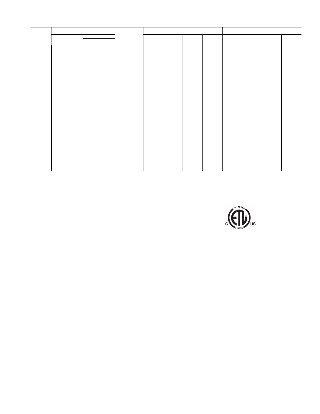
Table 18 — 30RAP Electrical Data — Single Point, No Hydronic Package (cont)
UNIT
30RAP
070
080
090
100
115
130
150
UNIT VOLTAGE
V-Hz
(3 Ph)
208/230-60 187 254 1 323.0 350 593.2 350 326.0 350 596.2 350
380-60 342 418 1 198.0 225 351.5 225 198.0 225 351.5 225
380/415-50 342 440 1 155.7 175 301.1 175 157.7 175 303.1 175
460-60 414 506 1 155.7 175 301.1 175 157.7 175 303.1 175
575-60 518 633 1 136.4 150 238.8 150 137.4 150 239.8 150
208/230-60 187 254 1 371.3 400 641.5 400 374.9 400 645.1 400
380-60 342 418 1 214.6 225 368.1 225 214.6 225 368.1 225
380/415-50 342 440 1 174.1 200 319.5 200 176.5 200 321.9 200
460-60 414 506 1 174.1 200 319.5 200 176.5 200 321.9 200
575-60 518 633 1 151.1 175 253.5 175 152.3 175 254.7 175
208/230-60 187 254 1 384.8 400 655.0 400 388.4 400 658.6 400
380-60 342 418 1 235.9 250 389.4 250 235.9 250 389.4 250
380/415-50 342 440 1 185.5 200 330.9 200 187.9 200 333.3 200
460-60 414 506 1 185.5 200 330.9 200 187.9 200 333.3 200
575-60 518 633 1 162.5 175 264.9 175 163.7 175 266.1 175
208/230-60 187 254 1 459.8 500 902.0 500 464.0 500 906.2 500
380-60 342 418 1 242.5 250 495.9 250 242.5 250 495.9 250
380/415-50 342 440 1 203.1 225 411.1 225 205.9 225 413.9 225
460-60 414 506 1 203.1 225 411.1 225 205.9 225 413.9 225
575-60 518 633 1 164.0 175 331.6 175 165.4 175 333.0 175
208/230-60 187 254 1 516.8 600 908.0 600 521.6 600 912.8 600
380-60 342 418 1 271.2 300 483.2 300 271.2 300 483.2 300
380/415-50 342 440 1 227.6 250 401.7 250 230.8 250 404.9 250
460-60 414 506 1 227.6 250 401.7 250 230.8 250 404.9 250
575-60 518 633 1 183.0 200 325.2 200 184.6 200 326.8 200
208/230-60 187 254 1 585.2 600 1027.4 600 590.6 600 1032.8 600
380-60 342 418 1 310.5 350 563.9 350 310.5 350 563.9 350
380/415-50 342 440 1 259.4 300 467.4 300 263.0 300 471.0 300
460-60 414 506 1 259.4 300 467.4 300 263.0 300 471.0 300
575-60 518 633 1 210.4 225 378.0 225 212.2 225 379.8 225
208/230-60 187 254 1 648.8 700 1091.0 700 654.8 700 1097.0 700
380-60 342 418 1 347.1 350 600.5 350 347.1 350 600.5 350
380/415-50 342 440 1 289.0 300 497.0 300 293.0 300 501.0 300
460-60 414 506 1 289.0 300 497.0 300 293.0 300 501.0 300
575-60 518 633 1 235.9 250 403.5 250 237.9 250 405.5 250
Supplied
Min Max
LEGEND
ICF — Instantaneous Current Flow
MCA — Minimum Circuit Amps
MOCP — Maximum Overcurrent Protection
NOTES:
1. Units are suitable for use on electrical systems where voltage supplied to
the unit terminals is not below or above the listed minimum and maximum
limits. Maximum allowable phase imbalance is: voltage 2%; amps 10%.
2. All units/modules have single point primary power connection. (Each unit/
module requires its own power supply.) Main power must be supplied from
a field-supplied disconnect.
3. Cooler heater is wired into the control circuit so it is always operable as
long as the power supply disconnect and heater safety device are on.
POWER
SUPPLY
QTY
REQD.
STANDARD LOW-SOUND AEROACOUSTIC™ FAN
NO HYDRONIC PACKAGE
MCA MOCP ICF
4. Power draw control circuits include both crankcase heaters and cooler
heaters (where used). Each compressor on sizes 070-090 has a crank
case heater which draws 90 watts of power at 60 Hz or 68 watts of power
at 50 Hz, while each compressor on sizes 100-150 has a crankcase
heater which draws 56 watts of power at 60 Hz or 42 watts of power at
50 Hz.
5. 30RAP chillers with Greenspeed® intelligence are not available on unit
sizes 010, 015, and 070-150.
Rec
Fuse
Size
NO HYDRONIC PACKAGE
OPTIONAL VALUE SOUND FANS
MCA MOCP ICF
Rec
Fuse
Size
-
47

Table 19 — 30RAP Electrical Data — Dual Point, Low-Sound Aeroacoustic™ Fan, No Hydronic Package
UNIT
30RAP
070
080
090
100
115
130
150
ICF — Instantaneous Current Flow
MCA — Minimum Circuit Amps
MOCP — Maximum Overcurrent Protection
NOTES:
1. Units are suitable for use on electrical systems where voltage supplied to
the unit terminals is not below or above the listed minimum and maximum
limits. Maximum allowable phase imbalance is: voltage 2%; amps 10%.
2. All units/modules have dual point primary power connection. (Each unit/
module requires its own power supply.) Main power must be supplied from
a field-supplied disconnect.
3. Cooler heater is wired into the control circuit so it is always operable as
long as the power supply disconnect and heater safety device are on.
UNIT VOLTAGE CIRCUIT 1 CIRCUIT 2
V-Ph-Hz
208/230-3-60 187 254 155.6 200 425.8 175 181.4 225 451.6 200
380-3-60 342 418 96.0 125 249.5 110 110.5 125 264.0 125
380/415-3-50 342 440 75.0 100 220.4 90 87.4 110 232.8 100
460-3-60 414 506 75.0 100 220.4 90 87.4 110 232.8 100
575-3-60 518 632 65.3 80 167.7 80 77.0 100 179.4 90
208/230-3-60 187 254 202.7 250 438.6 225 181.4 225 451.6 200
380-3-60 342 418 110.8 125 216.2 125 110.5 125 264.0 125
380/415-3-50 342 440 92.5 110 213.6 100 87.4 110 232.8 100
460-3-60 414 506 92.5 110 213.6 100 87.4 110 232.8 100
575-3-60 518 632 79.1 90 163.2 90 77.0 100 179.4 90
208/230-3-60 187 254 217.4 250 487.6 250 181.4 225 451.6 200
380-3-60 342 418 133.9 150 287.4 150 110.5 125 264.0 125
380/415-3-50 342 440 104.8 125 250.2 125 87.4 110 232.8 100
460-3-60 414 506 104.8 125 250.2 125 87.4 110 232.8 100
575-3-60 518 632 91.4 110 193.8 100 77.0 100 179.4 90
208/230-3-60 187 254 234.8 300 677.0 300 243.8 300 635.0 300
380-3-60 342 418 127.3 175 380.7 150 124.8 150 336.8 150
380/415-3-50 342 440 105.0 150 313.0 125 106.3 125 280.4 125
460-3-60 414 506 105.0 150 313.0 125 106.3 125 280.4 125
575-3-60 518 632 85.4 125 253.0 100 85.2 110 227.4 100
208/230-3-60 187 254 291.8 350 683.0 350 243.8 300 635.0 300
380-3-60 342 418 156.0 175 368.0 175 124.8 150 336.8 150
380/415-3-50 342 440 129.5 150 303.6 150 106.3 125 280.4 125
460-3-60 414 506 129.5 150 303.6 150 106.3 125 280.4 125
575-3-60 518 632 104.4 125 246.6 125 85.2 110 227.4 100
208/230-3-60 187 254 297.8 350 689.0 350 306.2 400 748.4 350
380-3-60 342 418 159.9 175 371.9 175 160.2 200 413.6 175
380/415-3-50 342 440 132.4 150 306.5 150 135.2 175 343.2 150
460-3-60 414 506 132.4 150 306.5 150 135.2 175 343.2 150
575-3-60 518 632 106.8 125 249.0 125 110.2 125 277.8 125
208/230-3-60 187 254 366.2 450 808.4 400 306.2 400 748.4 350
380-3-60 342 418 199.2 225 452.6 225 160.2 200 413.6 175
380/415-3-50 342 440 164.2 200 372.2 175 135.2 175 343.2 150
460-3-60 414 506 164.2 200 372.2 175 135.2 175 343.2 150
575-3-60 518 632 134.2 150 301.8 150 110.2 125 277.8 125
LEGEND
Supplied
Min Max
MCA MOCP ICF
Rec Fuse
Size
4. Power draw control circuits include both crankcase heaters and cooler
heaters (where used). Each compressor on sizes 070-090 has a crank
case heater which draws 90 watts of power at 60 Hz or 68 watts of power
at 50 Hz, while each compressor on sizes 100-150 has a crankcase
heater which draws 56 watts of power at 60 Hz or 42 watts of power at
50
Hz.
5. 30RAP chillers with Greenspeed® intelligence are not available on unit
sizes 010, 015, and 070-150.
MCA MOCP ICF
Rec Fuse
Size
-
48

Table 20 — 30RAP Electrical Data — Dual Point, Optional Value Sound Fan, No Hydronic Package
UNIT
30RAP
070
080
090
100
115
130
150
ICF — Instantaneous Current Flow
MCA — Minimum Circuit Amps
MOCP — Maximum Overcurrent Protection
NOTES:
1. Units are suitable for use on electrical systems where voltage supplied to
the unit terminals is not below or above the listed minimum and maximum
limits. Maximum allowable phase imbalance is: voltage 2%; amps 10%.
2. All units/modules have dual point primary power connection. (Each unit/
module requires its own power supply.) Main power must be supplied from
a field-supplied disconnect.
3. Cooler heater is wired into the control circuit so it is always operable as
long as the power supply disconnect and heater safety device are on.
UNIT VOLTAGE CIRCUIT 1 CIRCUIT 2
V-Ph-Hz
208/230-3-60 187 254 158.6 200 428.8 175 181.4 225 451.6 200
380-3-60 342 418 96.0 125 249.5 110 110.5 125 264.0 125
380/415-3-50 342 440 77.0 100 222.4 90 87.4 110 232.8 100
460-3-60 414 506 77.0 100 222.4 90 87.4 110 232.8 100
575-3-60 518 632 66.3 90 168.7 80 77.0 100 179.4 90
208/230-3-60 187 254 206.3 250 442.2 225 181.4 225 451.6 200
380-3-60 342 418 110.8 125 216.2 125 110.5 125 264.0 125
380/415-3-50 342 440 94.9 110 216.0 110 87.4 110 232.8 100
460-3-60 414 506 94.9 110 216.0 110 87.4 110 232.8 100
575-3-60 518 632 80.3 100 164.4 90 77.0 100 179.4 90
208/230-3-60 187 254 221.0 250 491.2 250 181.4 225 451.6 200
380-3-60 342 418 133.9 150 287.4 150 110.5 125 264.0 125
380/415-3-50 342 440 107.2 125 252.6 125 87.4 110 232.8 100
460-3-60 414 506 107.2 125 252.6 125 87.4 110 232.8 100
575-3-60 518 632 92.6 110 195.0 100 77.0 100 179.4 90
208/230-3-60 187 254 239.0 300 681.2 300 243.8 300 635.0 300
380-3-60 342 418 127.3 175 380.7 150 124.8 150 336.8 150
380/415-3-50 342 440 107.8 125 315.8 125 106.3 125 280.4 125
460-3-60 414 506 107.8 125 315.8 125 106.3 125 280.4 125
575-3-60 518 632 86.8 110 254.4 100 85.2 110 227.4 100
208/230-3-60 187 254 296.6 350 687.8 350 243.8 300 635.0 300
380-3-60 342 418 156.0 175 368.0 175 124.8 150 336.8 150
380/415-3-50 342 440 132.7 150 306.8 150 106.3 125 280.4 125
460-3-60 414 506 132.7 150 306.8 150 106.3 125 280.4 125
575-3-60 518 632 106.0 125 248.2 125 85.2 110 227.4 100
208/230-3-60 187 254 303.2 350 694.4 350 306.2 400 748.4 350
380-3-60 342 418 159.9 175 371.9 175 160.2 200 413.6 175
380/415-3-50 342 440 136.0 150 310.1 150 135.2 175 343.2 150
460-3-60 414 506 136.0 150 310.1 150 135.2 175 343.2 150
575-3-60 518 632 108.6 125 250.8 125 110.2 125 277.8 125
208/230-3-60 187 254 372.2 450 814.4 400 306.2 400 748.4 350
380-3-60 342 418 199.2 225 452.6 225 160.2 200 413.6 175
380/415-3-50 342 440 168.2 200 376.2 200 135.2 175 343.2 150
460-3-60 414 506 168.2 200 376.2 200 135.2 175 343.2 150
575-3-60 518 632 136.2 150 303.8 150 110.2 125 277.8 125
LEGEND
Supplied
Min Max
MCA MOCP ICF
Rec
Fuse
Size
4. Power draw control circuits include both crankcase heaters and cooler
heaters (where used). Each compressor on sizes 070-090 has a crank
case heater which draws 90 watts of power at 60 Hz or 68 watts of power
at 50 Hz, while each compressor on sizes 100-150 has a crankcase
heater which draws 56 watts of power at 60 Hz or 42 watts of power at
50
Hz.
5. 30RAP chillers with Greenspeed® intelligence are not available on unit
sizes 010, 015, and 070-150.
MCA MOCP ICF
Rec
Fuse
Size
-
49

Table 21 — 30RAP Electrical Data — Single Point, Hydronic Package with Standard Low-Sound
Aeroacoustic™ Fan (60 Hz Only)
30RAP UNIT
SIZE
010
011
015
016
018
020
025
030
035
040
045
050
055
060
VOLTAGE
V-Hz (3 Ph)
208/230-60 70.4 110 255.3 90 74.0 110 258.9 90 78.7 125 263.6 100
380-60 35.9 50 151.3 45 37.9 60 153.3 45 40.5 60 155.9 50
460-60 28.3 45 130.0 35 29.9 45 131.6 35 32.0 50 133.7 40
575-60 22.4 35 104.0 30 23.8 35 105.4 30 25.4 40 107.0 30
208/230-60 55.3 70 190.3 70 58.9 80 193.9 70 63.6 80 198.6 70
380-60 30.1 40 87.8 35 32.1 40 89.8 35 34.7 45 92.4 40
460-60 26.8 35 87.8 30 28.4 35 89.4 35 30.5 40 91.5 35
575-60 19.6 25 63.7 25 21.0 25 65.1 25 22.6 30 66.7 25
208/230-60 80.1 125 350.3 100 83.7 125 353.9 100 88.4 125 358.6 110
380-60 48.8 80 202.3 60 50.8 80 204.3
460-60 38.6 60 184.0 50 40.2 60 185.6 50 42.3 60 187.7 50
575-60 33.6 50 136.0 40 35.0 50 137.4
208/230-60 68.8 90 273.5 80 72.4 100 277.1 80 77.1 100 281.8 90
380-60 38.5 50 153.5 45 40.5 50 155.5 45 43.1 50 158.0 50
460-60 34.6 45 146.2 40 36.2 50 147.8 40 38.3 50 149.9 45
575-60 26.0 35 105.6 30 27.4 35 107.0 30 29.0 40 108.6 35
208/230-60 91.5 110 274.7 100 95.1 125 278.3 110 99.8 125 283.0 110
380-60 53.5 70 169.4 60 55.5 70 171.4 70 58.1 70 174.0 70
460-60 45.5 60 138.6 50 47.1 60 140.2 60 49.2 60 142.3 60
575-60 36.5 45 99.8 40 37.9 50 101.2 45 39.5 50 102.8 45
208/230-60 96.9 125 291.1 110 100.5 125 294.7 110 105.2 125 299.4 125
380-60 63.6 80 178.9 70 65.6 80 180.9 80 68.2 90 183.5 80
460-60 48.2 60 150.8 60 49.8 60 152.4 60 51.9 60 154.5 60
575-60 38.6 50 100.7 45 40.0 50 102.1 45 41.6 50 103.7 50
208/230-60 131.7 175 367.6 150 135.3 175 371.2 150 140.0 175 375.9 175
380-60 70.7 90 176.1 80 72.7 90 178.1 80 75.3 100 180.7 90
460-60 59.9 80 181.0 70 61.5 80 182.6 70 63.6 80 184.7 70
575-60 51.2 70 135.3 60 52.6 70 136.7 60 54.2 70 138.3 60
208/230-60 141.9 175 412.1 175 145.5 200 415.7 175 150.2 200 420.4 175
380-60 86.7 110 240.2 100 88.7 110 242.2 100 91.3 125 244.8 100
460-60 68.4 90 213.8 80 70.0 90 215.4 80 72.1 90 217.5 80
575-60 59.7 80 162.1 70 61.1 80 163.5 70 62.7 80 165.1 70
208/230-60 — — — — 173.3 200 367.5 200 178.0 200 372.2 200
380-60 — — — — 107.9 125 223.3 125 110.5 125 225.9 125
460-60 — — — — 86.1 100 188.7 100 88.2 100 190.8 100
575-60 — — — — 69.1 80 131.2 80 70.7 80 132.8 80
208/230-60 — — — — 205.7 250 402.9 225 210.4 250 407.6 225
380-60 — — — — 116.9 125 232.2 125 119.5 125 234.8 125
460-60 — — — — 90.1 100 192.5 100 92.2 110 194.6 100
575-60 — — — — 71.9 80 153.9 80 73.5 80 155.5 80
208/230-60 — — — — 237.5 250 476.6 250 242.2 250 481.3 250
380-60 — — — — 124.0 150 232.6 150 126.6 150 235.2 150
460-60 — — — — 101.6 110 227.2 110 103.7 125 229.3 110
575-60 — — — — 84.4 100 173.7 90 86.0 100 175.3 100
208/230-60 — — — — 243.9 250 479.8 250 248.6 250 484.5 250
380-60 — — — — 130.4 150 235.8 150 133.0 150 238.4 150
460-60 — — — — 110.6 125 231.7 125 112.7 125 233.8 125
575-60 — — — — 94.8 110 178.9 100 96.4 110 180.5 110
208/230-60 — — — — 260.1 300 534.8 300 264.8 300 539.5 300
380-60 — — — — 150.3 175 310.9 175 152.9 175 313.5 175
460-60 — — — — 122.0 125 271.2 125 124.1 150 273.3 150
575-60 — — — — 105.7 125 211.9 125 107.3 125 213.5 125
208/230-60 — — — — 269.1 300 539.3 300 273.8 300 544.0 300
380-60 — — — — 164.5 175 318.0 175 167.1 200 320.6 200
460-60 — — — — 129.6 150 275.0 150 131.7 150 277.1 150
575-60 — — — — 113.3 125 215.7 125 114.9 125 217.3 125
MCA MOCP ICF REC FUSE MCA MOCP ICF REC FUSE MCA MOCP ICF REC FUSE
LEGEND
ICF — Instantaneous Current Flow
MCA — Minimum Circuit Amps
MOCP — Maximum Overcurrent Protection
NOTES:
1. Units are suitable for use on electrical systems where voltage supplied to
the unit terminals is not below or above the listed minimum and maximum
limits. Maximum allowable phase imbalance is: voltage 2%; amps 10%.
2. All units/modules have single point primary power connection. (Each unit/
module requires its own power supply.) Main power must be supplied from
a field-supplied disconnect.
3. Cooler heater is wired into the control circuit so it is always operable as
long as the power supply disconnect and heater safety device are on.
PUMP SIZE 1.5 hp PUMP SIZE 3.0 hp PUMP SIZE 5.0 hp
60 53.4 80 206.9 70
45 36.6 60 139.0 45
4. Power draw control circuits include both crankcase heaters (sizes 070150 only) and cooler heaters (where used). Each compressor on sizes
070-090 has a crankcase heater which draws 90 watts of power, while
each compressor on sizes 100-150 has a crankcase heater which draws
56 watts of power.
5. 30RAP chillers with Greenspeed® intelligence are not available on unit
sizes 010, 015, and 070-150.
50
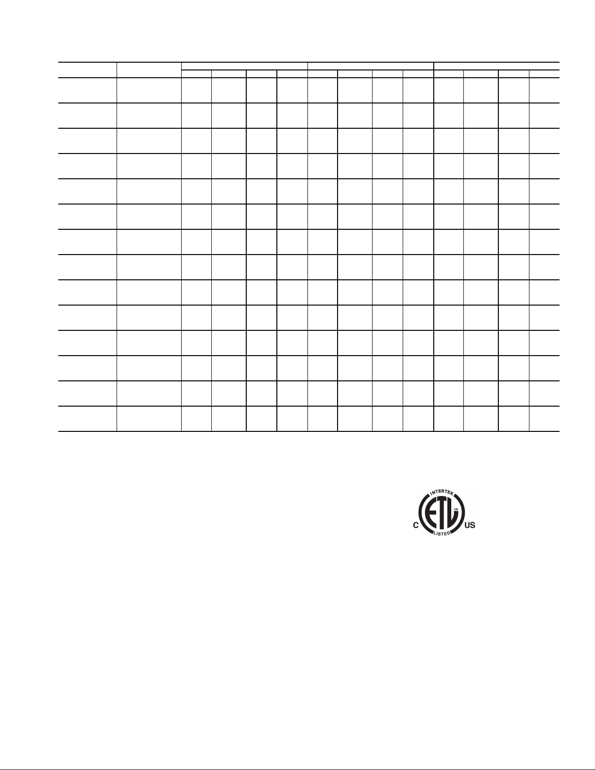
Table 21 — 30RAP Electrical Data — Single Point, Hydronic Package with Standard Low-Sound
Aeroacoustic™ Fan (60 Hz Only) (cont)
30RAP UNIT SIZE
010
011
015
016
018
020
025
030
035
040
045
050
055
060
VOLTAGE
V-Hz (3 Ph)
208/230-60 — — — — — — — — — — — —
380-60 ————————————
460-60 ————————————
575-60 ————————————
208/230-60 — — — — — — — — — — — —
380-60 ————————————
460-60 ————————————
575-60 ————————————
208/230-60 — — — — — — — — — — — —
380-60 ————————————
460-60 ————————————
575-60 ————————————
208/230-60 — — — — — — — — — — — —
380-60 ————————————
460-60 ————————————
575-60 ————————————
208/230-60 — — — — — — — — — — — —
380-60 ————————————
460-60 ————————————
575-60 ————————————
208/230-60 — — — — — — — — — — — —
380-60 ————————————
460-60 ————————————
575-60 ————————————
208/230-60 — — — — — — — — — — — —
380-60 ————————————
460-60 ————————————
575-60 ————————————
208/230-60 — — — — — — — — — — — —
380-60 ————————————
460-60 ————————————
575-60 ————————————
208/230-60 183.9 200 378.1 200 — — — — — — — —
380-60 113.9 125 229.3 125 — — — — — — — —
460-60 91.1 100 193.7 100 — — — — — — — —
575-60 73.1 80 135.2 80 — — — — — — — —
208/230-60 216.3 250 413.5 250 — — — — — — — —
380-60 122.9 125 238.2 125 — — — — — — — —
460-60 95.1 110 197.5 100 — — — — — — — —
575-60 75.9 90 157.9 80 — — — — — — — —
208/230-60 248.1 250 487.2 250 — — — — — — — —
380-60 130.0 150 238.6 150 — — — — — — — —
460-60 106.6 125 232.2 125 — — — — — — — —
575-60 88.4 100 177.7 100 — — — — — — — —
208/230-60 254.5 300 490.4 300 261.0 300 496.9 300 — — — —
380-60 136.4 150 241.8 150 140.0 150 245.4 150 — — — —
460-60 115.6 125 236.7 125 118.4 125 239.5 125 — — — —
575-60 98.8 110 182.9 110 101.0 110 185.1 110 — — — —
208/230-60 270.7 300 545.4 300 277.2 300 551.9 300 — — — —
380-60 156.3 175 316.9 175 159.9 175 320.5 175 — — — —
460-60 127.0 150 276.2 150 129.8 150 279.0 150 — — — —
575-60 109.7 125 215.9 125 111.9 125 218.1 125 — — — —
208/230-60 279.7 300 549.9 300 286.2 300 556.4 300 — — — —
380-60 170.5 200 324.0 200 174.1 200 327.6 200 — — — —
460-60 134.6 150 280.0 150 137.4 150 282.8 150 — — — —
575-60 117.3 125 219.7 125 119.5 125 221.9 125 — — — —
MCA MOCP ICF REC FUSE MCA MOCP ICF REC FUSE MCA MOCP ICF REC FUSE
LEGEND
ICF — Instantaneous Current Flow
MCA — Minimum Circuit Amps
MOCP — Maximum Overcurrent Protection
NOTES:
1. Units are suitable for use on electrical systems where voltage supplied to
the unit terminals is not below or above the listed minimum and maximum
limits. Maximum allowable phase imbalance is: voltage 2%; amps 10%.
2. All units/modules have single point primary power connection. (Each unit/
module requires its own power supply.) Main power must be supplied from
a field-supplied disconnect.
3. Cooler heater is wired into the control circuit so it is always operable as
long as the power supply disconnect and heater safety device are on.
PUMP SIZE 7.5 hp PUMP SIZE 10.0 hp PUMP SIZE 15.0 hp
4. Power draw control circuits include both crankcase heaters (sizes 070150 only) and cooler heaters (where used). Each compressor on sizes
070-090 has a crankcase heater which draws 90 watts of power, while
each compressor on sizes 100-150 has a crankcase heater which draws
56 watts of power.
5. 30RAP chillers with Greenspeed® intelligence are not available on unit
sizes 010, 015, and 070-150.
51

Table 21 — 30RAP Electrical Data — Single Point, Hydronic Package with Standard Low-Sound
LEGEND
®
intelligence are not available on unit
30RAP UNIT SIZE
070
080
090
100
115
130
150
30RAP UNIT SIZE
070
080
090
100
115
130
150 Dual Pump
150 Single Pump
30RAP UNIT SIZE
070
080
090
100
115
130
150
Aeroacoustic™ Fan (60 Hz Only) (cont)
VOLTAGE
V-Hz (3 Ph)
208/230-60 — — — — 332.1 350 602.3 350 338.4 350 608.6 350
380-60 — — — — 203.1 225 356.6 225 206.1 225 359.6 225
460-60 — — — — 159.9 175 305.3 175 162.8 175 308.2 175
575-60 — — — — 139.7 150 242.1 150 141.8 150 244.2 150
208/230-60 — — — — — — — — 386.7 400 656.9 400
380-60 — — — — — — — — 222.7 250 376.2 250
460-60 — — — — — — — — 181.2 200 326.6 200
575-60 — — — — — — — — 156.5 175 258.9 175
208/230-60 — — — — — — — — 400.2 450 670.4 450
380-60 — — — — — — — — 244.0 250 397.5 250
460-60 — — — — — — — — 192.6 200 338.0 200
575-60 — — — — — — — — 167.9 175 270.3 175
208/230-60 — — — — — — — — 475.2 500 917.4 500
380-60 — — — — — — — — 250.6 300 504.0 300
460-60 — — — — — — — — 210.2 250 418.2 225
575-60 — — — — — — — — 169.4 200 337.0 200
208/230-60 — — — — — — — — 532.2 600 923.4 600
380-60 — — — — — — — — 279.3 300 491.3 300
460-60 — — — — — — — — 234.7 250 408.8 250
575-60 — — — — — — — — 188.4 200 330.6 200
208/230-60 — — — — — — — — 600.6 700 1042.8 700
380-60 — — — — — — — — 318.6 350 572.0 350
460-60 — — — — — — — — 266.5 300 474.5 300
575-60 — — — — — — — — 215.8 225 383.4 225
208/230-60 — — — — — — — — 664.2 700 1106.4 700
380-60 — — — — — — — — 355.2 400 608.6 400
460-60 — — — — — — — — 296.1 300 504.1 300
575-60 — — — — — — — — 241.3 250 408.9 250
VOLTAGE
V-Hz (3 Ph)
208/230-60 341.5 350 611.7 350
380-60 208.4 225 361.9 225
460-60 164.4 175 309.8 175
575-60 143.4 150 245.8 150
208/230-60 389.8 400 660.0 400
380-60 225.0 250 378.5 250
460-60 182.8 200 328.2 200
575-60 158.1 175 260.5 175
208/230-60 403.3 450 673.5 450
380-60 246.3 250 399.8 250
460-60 194.2 200 339.6 200
575-60 169.5 175 271.9 175
208/230-60 478.3 500 920.5 500
380-60 252.9 300 506.3 300
460-60 211.8 250 419.8 225
575-60 171.0 200 338.6 200
208/230-60 535.3 600 926.5 600
380-60 281.6 300 493.6 300
460-60 236.3 250 410.4 250
575-60 190.0 200 332.2 200
208/230-60 603.7 700 1045.9 700
380-60 320.9 350 574.3 350
460-60 268.1 300 476.1 300
575-60 217.4 250 385.0 250
208/230-60 667.3 700 1109.5 700
380-60 357.5 400 610.9 400
460-60 297.7 300 505.7 300
575-60 242.9 250 410.5 250
208/230-60 670.8 700 1113.0 700
380-60 359.4 400 612.8 400
460-60 299.1 300 507.1 300
575-60 244.0 250 411.6 250
VOLTAGE
V-Hz (3 Ph)
208/230-60 348.0 400 618.2 400 — — — —
380-60 212.0 225 365.5 225 — — — —
460-60 167.2 175 312.6 175 — — — —
575-60 145.6 150 248.0 150 — — — —
208/230-60 396.3 450 666.5 450 408.0 450 678.2 450
380-60 228.6 250 382.1 250 235.6 250 389.1 250
460-60 185.6 200 331.0 200 191.1 200 336.5 200
575-60 160.3 175 262.7 175 165.1 175 267.5 175
208/230-60 409.8 450 680.0 450 421.5 450 691.7 450
380-60 249.9 250 403.4 250 256.9 300 410.4 300
460-60 197.0 200 342.4 200 202.5 225 347.9 225
575-60 171.7 175 274.1 175 176.5 200 278.9 200
208/230-60 484.8 500 927.0 500 496.5 500 938.7 500
380-60 256.5 300 509.9 300 263.5 300 516.9 300
460-60 214.6 250 422.0 250 220.1 250 428.1 250
575-60 173.2 200 340.8 200 178.0 200 345.6 200
208/230-60 541.8 600 933.0 600 553.5 600 944.7 600
380-60 285.2 300 497.2 300 292.2 300 504.2 300
460-60 239.1 250 413.2 250 244.6 250 418.7 250
575-60 192.2 200 334.4 200 197.0 200 339.2 200
208/230-60 610.2 700 1052.4 700 621.9 700 1064.1 700
380-60 324.5 350 577.9 350 331.5 350 584.9 350
460-60 270.9 300 478.9 300 276.4 300 484.4 300
575-60 219.6 250 387.2 250 224.4 250 392.0 250
208/230-60 673.8 700 1116.0 700 685.5 700 1127.7 700
380-60 361.1 400 614.5 400 368.1 400 621.5 400
460-60 300.5 350 508.5 350 306.0 350 514.0 350
575-60 245.1 250 412.7 250 249.9 250 417.5 250
MCA MOCP ICF REC FUSE MCA MOCP ICF REC FUSE MCA MOCP ICF REC FUSE
MCA MOCP ICF REC FUSE
MCA MOCP ICF REC FUSE MCA MOCP ICF REC FUSE
PUMP SIZE 1.5 hp PUMP SIZE 3.0 hp PUMP SIZE 5.0 hp
PUMP SIZE 7.5 hp
ICF — Instantaneous Current Flow
MCA — Minimum Circuit Amps
MOCP — Maximum Overcurrent Protection
NOTES:
1. Units are suitable for use on electrical systems where voltage supplied to
the unit terminals is not below or above the listed minimum and maximum
limits. Maximum allowable phase imbalance is: voltage 2%; amps 10%.
2. All units/modules have single point primary power connection. (Each unit/
module requires its own power supply.) Main power must be supplied
from a field-supplied disconnect.
3. Cooler heater is wired into the control circuit so it is always operable as
long as the power supply disconnect and heater safety device are on.
4. Power draw control circuits include both crankcase heaters (sizes 070150 only) and cooler heaters (where used). Each compressor on sizes
070-090 has a crankcase heater which draws 90 watts of power, while
each compressor on sizes 100-150 has a crankcase heater which draws
56 watts of power.
5. 30RAP chillers with Greenspeed
sizes 010, 015, and 070-150.
6. All data is the same for single pump or dual pump except for size 150 with
7.5 hp pump.
PUMP SIZE 10.0 hp PUMP SIZE 15.0 hp
52

Table 22 — 30RAP Electrical Data — Dual Point, Hydronic Package with Standard Low-Sound Aeroacoustic™
Fan (60 Hz Only)
30RAP UNIT
SIZE
070
080
090
100
115
130
150
VOLTAGE
V-Ph-Hz
208/230-3-60 155.6 200 425.8 175 190.5 225 460.7 225
380-3-60 96.0 125 249.5 110 115.6 125 269.1 125
460-3-60 75.0 100 220.4 90 91.6 110 237.0 100
575-3-60 65.3 80 167.7 80 80.3 100 182.7 90
208/230-3-60 — — — — — — — —
380-3-60 — — — — — — — —
460-3-60 — — — — — — — —
575-3-60 — — — — — — — —
208/230-3-60 — — — — — — — —
380-3-60 — — — — — — — —
460-3-60 — — — — — — — —
575-3-60 — — — — — — — —
208/230-3-60 — — — — — — — —
380-3-60 — — — — — — — —
460-3-60 — — — — — — — —
575-3-60 — — — — — — — —
208/230-3-60 — — — — — — — —
380-3-60 — — — — — — — —
460-3-60 — — — — — — — —
575-3-60 — — — — — — — —
208/230-3-60 — — — — — — — —
380-3-60 — — — — — — — —
460-3-60 — — — — — — — —
575-3-60 — — — — — — — —
208/230-3-60 — — — — — — — —
380-3-60 — — — — — — — —
460-3-60 — — — — — — — —
575-3-60 — — — — — — — —
MCA MOCP ICF REC FUSE MCA MOCP ICF REC FUSE
PUMP SIZE 3.0 HP PUMP SIZE 3.0 HP
CIRCUIT 1 CIRCUIT 2
30RAP UNIT
SIZE
070
080
090
100
115
130
150
VOLTAGE
V-Ph-Hz
208/230-3-60 155.6 200 425.8 175 196.8 250 467.0 225
380-3-60 96.0 125 249.5 110 118.6 150 272.1 150
460-3-60 75.0 100 220.4 90 94.5 110 241.5 110
575-3-60 65.3 80 167.7 80 82.4 100 184.8 90
208/230-3-60 202.7 250 438.6 225 196.8 250 467.0 225
380-3-60 110.8 125 216.2 125 118.6 150 272.1 150
460-3-60 92.5 110 213.6 100 94.5 110 239.9 110
575-3-60 79.1 90 163.2 90 82.4 100 184.8 90
208/230-3-60 217.4 250 487.6 250 196.8 250 467.0 225
380-3-60 133.9 150 287.4 150 118.6 150 272.1 150
460-3-60 104.8 125 250.2 125 94.5 110 239.9 110
575-3-60 91.4 110 193.8 100 82.4 100 184.8 90
208/230-3-60 234.8 300 677.0 300 259.2 300 650.4 300
380-3-60 127.3 175 380.7 150 132.9 150 344.9 150
460-3-60 105.0 125 313.0 125 113.4 125 287.5 125
575-3-60 85.4 110 253.0 100 90.6 110 232.8 100
208/230-3-60 291.8 350 683.0 350 259.2 300 650.4 300
380-3-60 156.0 175 368.0 175 132.9 150 344.9 150
460-3-60 129.5 150 303.6 150 113.4 125 287.5 125
575-3-60 104.4 125 246.6 125 90.6 110 232.8 100
208/230-3-60 297.8 350 689.0 350 321.6 400 763.8 350
380-3-60 159.9 175 371.9 175 168.3 200 421.7 200
460-3-60 132.4 150 306.5 150 142.3 175 350.3 175
575-3-60 106.8 125 249.0 125 115.6 125 283.2 125
208/230-3-60 366.2 450 808.4 400 321.6 400 763.8 350
380-3-60 199.2 225 452.6 225 168.3 200 421.7 200
460-3-60 164.2 200 372.2 175 142.3 175 350.3 175
575-3-60 134.2 150 301.8 150 115.6 125 283.2 125
MCA MOCP ICF REC FUSE MCA MOCP ICF REC FUSE
PUMP SIZE 5.0 HP PUMP SIZE 5.0 HP
CIRCUIT 1 CIRCUIT 2
LEGEND
ICF — Instantaneous Current Flow
MCA — Minimum Circuit Amps
MOCP — Maximum Overcurrent Protection
NOTES:
1. Units are suitable for use on electrical systems where voltage supplied to
the unit terminals is not below or above the listed minimum and maximum
limits. Maximum allowable phase imbalance is: voltage 2%; amps 10%.
2. All units/modules have single point primary power connection. (Each unit/
module requires its own power supply.) Main power must be supplied from
a field-supplied disconnect.
3. Cooler heater is wired into the control circuit so it is always operable as
long as the power supply disconnect and heater safety device are on.
4. Power draw control circuits include both crankcase heaters (sizes 070150 only) and cooler heaters (where used). Each compressor on sizes
070-090 has a crankcase heater which draws 90 watts of power, while
each compressor on sizes 100-150 has a crankcase heater which draws
56 watts of power.
5. 30RAP chillers with Greenspeed® intelligence are not available on unit
sizes 010, 015, and 070-150.
53

Table 22 —
30RAP UNIT
SIZE
070
080
090
100
115
130
150 Dual Pump
150 Single Pump
30RAP Electrical Data — Dual Point, Hydronic Package with Standard Low-Sound Aeroacoustic™
Fan (60 Hz Only) (cont)
VOLTAGE
V-Ph-Hz
208/230-3-60 155.6 200 425.8 175 199.9 250 470.1 225
380-3-60 96.0 125 249.5 110 120.9 150 274.4 150
460-3-60 75.0 100 220.4 90 96.1 110 241.5 110
575-3-60 65.3 80 167.7 80 84.0 100 186.4 90
208/230-3-60 202.7 250 438.6 225 199.9 250 470.1 225
380-3-60 110.8 125 216.2 125 120.9 150 274.4 150
460-3-60 92.5 110 213.6 100 96.1 110 241.5 110
575-3-60 79.1 90 163.2 90 84.0 100 186.4 90
208/230-3-60 217.4 250 487.6 250 199.9 250 470.1 225
380-3-60 133.9 150 287.4 150 120.9 150 274.4 150
460-3-60 104.8 125 250.2 125 96.1 110 241.5 110
575-3-60 91.4 110 193.8 100 84.0 100 186.4 90
208/230-3-60 234.8 300 677.0 300 262.3 300 653.5 300
380-3-60 127.3 175 380.7 150 135.2 150 347.2 150
460-3-60 105.0 125 313.0 125 115.0 125 289.1 125
575-3-60 85.4 110 253.0 100 92.2 110 234.4 100
208/230-3-60 291.8 350 683.0 350 262.3 300 653.5 300
380-3-60 156.0 175 368.0 175 135.2 150 347.2 150
460-3-60 129.5 150 303.6 150 115.0 125 289.1 125
575-3-60 104.4 125 246.6 125 92.2 110 234.4 100
208/230-3-60 297.8 350 689.0 350 324.7 400 766.9 350
380-3-60 159.9 175 371.9 175 170.6 200 424.0 200
460-3-60 132.4 150 306.5 150 143.9 175 351.9 175
575-3-60 106.8 125 249.0 125 117.2 150 284.8 150
208/230-3-60 366.2 450 808.4 400 324.7 400 766.9 350
380-3-60 199.2 225 452.6 225 170.6 200 424.0 200
460-3-60 164.2 200 372.2 175 143.9 175 351.9 175
575-3-60 134.2 150 301.8 150 117.2 150 284.8 150
208/230-3-60 366.2 450 808.4 400 328.2 400 770.4 350
380-3-60 199.2 225 452.6 225 172.5 200 425.9 200
460-3-60 164.2 200 372.2 175 145.3 175 353.3 175
575-3-60 134.2 150 301.8 150 118.3 150 285.9 150
MCA MOCP ICF REC FUSE MCA MOCP ICF REC FUSE
PUMP SIZE 7.5 HP PUMP SIZE 7.5 HP
CIRCUIT 1 CIRCUIT 2
30RAP UNIT
SIZE
070
080
090
100
115
130
150
VOLTAGE
V-Ph-Hz
208/230-3-60 155.6 200 425.8 175 206.4 250 476.6 225
380-3-60 96.0 125 249.5 110 124.5 150 278.0 150
460-3-60 75.0 100 220.4 90 98.9 125 244.3 110
575-3-60 65.3 80 167.7 80 86.2 100 188.6 100
208/230-3-60 202.7 250 438.6 225 206.4 250 476.6 225
380-3-60 110.8 125 216.2 125 124.5 150 278.0 150
460-3-60 92.5 110 213.6 100 98.9 125 244.3 110
575-3-60 79.1 90 163.2 90 86.2 100 188.6 100
208/230-3-60 217.4 250 487.6 250 206.4 250 476.6 225
380-3-60 133.9 150 287.4 150 124.5 150 278.0 150
460-3-60 104.8 125 250.2 125 98.9 125 244.3 110
575-3-60 91.4 110 193.8 100 86.2 100 188.6 100
208/230-3-60 234.8 300 677.0 300 268.8 300 660.0 300
380-3-60 127.3 175 380.7 150 138.8 175 350.8 150
460-3-60 105.0 125 313.0 125 117.8 150 291.9 150
575-3-60 85.4 110 253.0 100 94.4 110 236.6 110
208/230-3-60 291.8 350 683.0 350 268.8 300 660.0 300
380-3-60 156.0 175 368.0 175 138.8 175 350.8 150
460-3-60 129.5 150 303.6 150 117.8 150 291.9 150
575-3-60 104.4 125 246.6 125 94.4 110 236.6 110
208/230-3-60 297.8 350 689.0 350 331.2 400 773.4 400
380-3-60 159.9 175 371.9 175 174.2 225 427.6 200
460-3-60 132.4 150 306.5 150 146.7 175 354.7 150
575-3-60 106.8 125 249.0 125 119.4 150 287.0 150
208/230-3-60 366.2 450 808.4 400 331.2 400 773.4 400
380-3-60 199.2 225 452.6 225 174.2 225 427.6 200
460-3-60 164.2 200 372.2 175 146.7 175 354.7 150
575-3-60 134.2 150 301.8 150 119.4 150 287.0 150
MCA MOCP ICF REC FUSE MCA MOCP ICF REC FUSE
PUMP SIZE 10.0 HP PUMP SIZE 10.0 HP
CIRCUIT 1 CIRCUIT 2
LEGEND
ICF — Instantaneous Current Flow
MCA — Minimum Circuit Amps
MOCP — Maximum Overcurrent Protection
NOTES:
1. Units are suitable for use on electrical systems where voltage supplied to
the unit terminals is not below or above the listed minimum and maximum
limits. Maximum allowable phase imbalance is: voltage 2%; amps 10%.
2. All units/modules have single point primary power connection. (Each unit/
module requires its own power supply.) Main power must be supplied from
a field-supplied disconnect.
3. Cooler heater is wired into the control circuit so it is always operable as
long as the power supply disconnect and heater safety device are on.
4. Power draw control circuits include both crankcase heaters (sizes 070150 only) and cooler heaters (where used). Each compressor on sizes
070-090 has a crankcase heater which draws 90 watts of power, while
each compressor on sizes 100-150 has a crankcase heater which draws
56 watts of power.
5. 30RAP chillers with Greenspeed® intelligence are not available on unit
sizes 010, 015, and 070-150.
54

Table 22 — 30RAP Electrical Data — Dual Point, Hydronic Package with Standard Low-Sound Aeroacoustic™
Fan (60 Hz Only) (cont)
30RAP UNIT
SIZE
070
080
090
100
115
130
150
VOLTAGE
V-Ph-Hz
208/230-3-60 — — — — — — — —
380-3-60 — — — — — — — —
460-3-60 — — — — — — — —
575-3-60 — — — — — — — —
208/230-3-60 202.7 250 438.6 225 218.1 250 488.3 250
380-3-60 110.8 125 216.2 125 131.5 150 285.0 150
460-3-60 92.5 110 213.6 100 104.4 125 249.8 125
575-3-60 79.1 90 163.2 90 91.0 110 193.4 100
208/230-3-60 217.4 250 487.6 250 218.1 250 488.3 250
380-3-60 133.9 150 287.4 150 131.5 150 285.0 150
460-3-60 104.8 125 250.2 125 104.4 125 249.8 125
575-3-60 91.4 110 193.8 100 91.0 110 193.4 100
208/230-3-60 234.8 300 677.0 300 280.5 350 671.7 300
380-3-60 127.3 175 380.7 150 145.8 175 357.8 175
460-3-60 105.0 125 313.0 125 123.3 150 297.4 150
575-3-60 85.4 110 253.0 100 99.2 125 241.4 110
208/230-3-60 291.8 350 683.0 350 280.5 350 671.7 300
380-3-60 156.0 175 368.0 175 145.8 175 357.8 175
460-3-60 129.5 150 303.6 150 123.3 150 297.4 150
575-3-60 104.4 125 246.6 125 99.2 125 241.4 110
208/230-3-60 297.8 350 689.0 350 342.9 400 785.1 400
380-3-60 159.9 175 371.9 175 181.2 225 434.6 200
460-3-60 132.4 150 306.5 150 152.2 175 360.2 175
575-3-60 106.8 125 249.0 125 124.2 150 291.8 150
208/230-3-60 366.2 450 808.4 400 342.9 400 785.1 400
380-3-60 199.2 225 452.6 225 181.2 225 434.6 200
460-3-60 164.2 200 372.2 175 152.2 175 360.2 175
575-3-60 134.2 150 301.8 150 124.2 150 291.8 150
MCA MOCP ICF REC FUSE MCA MOCP ICF REC FUSE
PUMP SIZE 15.0 HP PUMP SIZE 15.0 HP
CIRCUIT 1 CIRCUIT 2
LEGEND
ICF — Instantaneous Current Flow
MCA — Minimum Circuit Amps
MOCP — Maximum Overcurrent Protection
NOTES:
1. Units are suitable for use on electrical systems where voltage supplied to
the unit terminals is not below or above the listed minimum and maximum
limits. Maximum allowable phase imbalance is: voltage 2%; amps 10%.
2. All units/modules have dual point primary power connection. (Each unit /
module requires its own power supply.) Main power must be supplied from
a field-supplied disconnect.
3. Cooler heater is wired into the control circuit so it is always operable as
long as the power supply disconnect and heater safety device are on.
4. Power draw control circuits include both crankcase heaters (sizes 070150 only) and cooler heaters (where used). Each compressor on sizes
070-090 has a crankcase heater which draws 90 watts of power, while
each compressor on sizes 100-150 has a crankcase heater which draws
56 watts of power.
5. 30RAP chillers with Greenspeed® intelligence are not available on unit
sizes 010, 015, and 070-150.
55

Table 23 — 30RAP Electrical Data — Single Point, Hydronic Package with Optional Value Sound Fans
(60 Hz Only)
30RAP UNIT
SIZE
010
011
015
016
018
020
025
030
035
040
045
050
055
060
VOLTAGE
V-Hz (3 Ph)
208/230-60 71.0 110 255.9 90 74.6 110 259.5 90 79.3 125 264.2 100
380-60 35.9 50 151.3 45 37.9 60 153.3 45 40.5 60 155.9 50
460-60 28.7 45 130.4 35 30.3 45 132.0 35 32.4 50 134.1 40
575-60 22.6 35 104.2 30 24.0 35 105.6 30 25.6 40 107.2 30
208/230-60 55.9 70 190.9 70 59.5 80 194.5 70 64.2 80 199.2 70
380-60 30.1 40 87.8 35 32.1 40 89.8 35 34.7 45 92.4 40
460-60 27.2 35 88.2 30 28.8 40 89.8 35 30.9 40 91.9 35
575-60 19.8 25 63.9 25 21.2 25 65.3 25 22.8 30 66.9 25
208/230-60 80.7 125 350.9 100 84.3 125 354.5 100 89.0 125 359.2 110
380-60 48.8 80 202.3
460-60 39.0 60 184.4 50 40.6 60 186.0 50 42.7 60 188.1 50
575-60 33.8 50 136.2
208/230-60 69.4 90 274.1 80 73.0 100 277.7 90 77.7 100 282.4 90
380-60 38.5 50 153.5 45 40.5 50 155.5 45 43.1 50 158.1 50
460-60 35.0 45 146.6 40 36.6 50 148.2 45 38.7 50 150.3 45
575-60 26.2 35 105.8 30 27.6 35 107.2 35 29.2 40 108.8 35
208/230-60 92.7 125 275.9 110 96.3 125 279.5 110 101.0 125 284.2 110
380-60 53.5 70 169.4 60 55.5 70 171.4 70 58.1 70 174.0 70
460-60 46.3 60 139.4 60 47.9 60 141.0 60 50.0 60 143.1 60
575-60 36.9 50 100.2 45 38.3 50 101.6 45 39.9 50 103.2 45
208/230-60 98.1 125 292.3 110 101.7 125 295.9 125 106.4 125 300.6 125
380-60 63.6 80 178.9 70 65.6 80 180.9 80 68.2 90 183.5 80
460-60 49.0 60 151.6 60 50.6 60 153.2 60 52.7 70 155.3 60
575-60 39.0 50 101.1 45 40.4 50 102.5 45 42.0 50 104.1 50
208/230-60 132.9 175 368.8 150 136.5 175 372.4 150 141.2 175 377.1 175
380-60 70.7 90 176.1 80 72.7 90 178.1 80 75.3 100 180.7 90
460-60 60.7 80 181.8 70 62.3 80 183.4 70 64.4 80 185.5 80
575-60 51.6 70 135.7 60 53.0 70 137.1 60 54.6 70 138.7 60
208/230-60 143.1 175 413.3 175 146.7 200 416.9 175 151.4 200 421.6 175
380-60 86.7 110 240.2 100 88.7 110 242.2 100 91.3 125 244.8 100
460-60 69.2 90 214.6 80 70.8 90 216.2 80 72.9 90 218.3 80
575-60 60.1 80 162.5 70 61.5 80 163.9 70 63.1 80 165.5 70
208/230-60 — — — — 175.1 200 369.3 200 179.8 200 374.0 200
380-60 — — — — 107.9 125 223.2 125 110.5 125 225.9 125
460-60 — — — — 87.3 100 189.9 100 89.4 100 192.0 100
575-60 — — — — 69.7 80 131.8 80 71.3 80 133.4 80
208/230-60 — — — — 207.5 250 404.7 225 212.2 250 409.4 225
380-60 — — — — 116.9 125 232.2 125 119.5 125 234.8 125
460-60 — — — — 91.3 100 193.7 100 93.4 110 195.8 100
575-60 — — — — 72.5 80 154.5 80 74.1 80 156.1 80
208/230-60 — — — — 239.3 250 478.4 250 244.0 250 483.1 250
380-60 — — — — 124.0 150 232.6 150 126.6 150 235.2 150
460-60 — — — — 102.8 125 228.4 110 104.9 125 230.5 125
575-60 — — — — 85.0 100 174.3 90 86.6 100 175.9 100
208/230-60 — — — — 245.7 250 481.6 250 250.4 300 486.3 300
380-60 — — — — 130.4 150 235.8 150 133.0 150 238.4 150
460-60 — — — — 111.8 125 232.9 125 113.9 125 235.0 125
575-60 — — — — 95.4 110 179.5 110 97.0 110 181.1 110
208/230-60 — — — — 262.5 300 537.2 300 267.2 300 541.9 300
380-60 — — — — 150.3 175 310.9 175 152.9 175 313.5 175
460-60 — — — — 123.6 150 272.8 150 125.7 150 274.9 150
575-60 — — — — 106.5 125 212.7 125 108.1 125 214.3 125
208/230-60 — — — — 271.5 300 541.7 300 276.2 300 546.4 300
380-60 — — — — 164.5 175 318.0 175 167.1 200 320.6 200
460-60 — — — — 131.2 150 276.6 150 133.3 150 278.7 150
575-60 — — — — 114.1 125 216.5 125 115.7 125 218.1 125
MCA MOCP ICF REC FUSE MCA MOCP ICF REC FUSE MCA MOCP ICF REC FUSE
LEGEND
ICF — Instantaneous Current Flow
MCA — Minimum Circuit Amps
MOCP — Maximum Overcurrent Protection
NOTES:
1. Units are suitable for use on electrical systems where voltage supplied to
the unit terminals is not below or above the listed minimum and maximum
limits. Maximum allowable phase imbalance is: voltage 2%; amps 10%.
2. All units/modules have single point primary power connection. (Each unit/
module requires its own power supply.) Main power must be supplied from
a field-supplied disconnect.
PUMP SIZE 1.5 HP PUMP SIZE 3.0 HP PUMP SIZE 5.0 HP
60 50.8 80 204.3 60 53.4 80 206.9 70
40 35.2 50 137.6 45 36.8 60 139.2 45
3. Cooler heater is wired into the control circuit so it is always operable as
long as the power supply disconnect and heater safety device are on.
4. Power draw control circuits include both crankcase heaters (sizes 070150 only) and cooler heaters (where used). Each compressor on sizes
070-090 has a crankcase heater which draws 90 watts of power, while
each compressor on sizes 100-150 has a crankcase heater which draws
56 watts of power.
5. 30RAP chillers with Greenspeed® intelligence are not available on unit
sizes 010, 015, and 070-150.
n
56

Table 23 — 30RAP Electrical Data — Single Point, Hydronic Package with Optional Value Sound Fans
(60 Hz Only) (cont)
30RAP UNIT
SIZE
070
080
090
100
115
130
150
VOLTAGE
V-Hz (3 Ph)
208/230-60 — — — —
380-60 — — — —
460-60 — — — —
575-60 — — — —
208/230-60 — — — — — — — —
380-60————————
460-60————————
575-60————————
208/230-60 — — — — — — — —
380-60————————
460-60————————
575-60————————
208/230-60 — — — — — — — —
380-60————————
460-60————————
575-60————————
208/230-60 — — — — — — — —
380-60————————
460-60————————
575-60————————
208/230-60 — — — — — — — —
380-60————————
460-60————————
575-60————————
208/230-60 — — — — — — — —
380-60————————
460-60————————
575-60————————
MCA MOCP ICF REC FUSE MCA MOCP ICF REC FUSE MCA MOCP ICF REC FUSE
LEGEND
ICF — Instantaneous Current Flow
MCA — Minimum Circuit Amps
MOCP — Maximum Overcurrent Protection
NOTES:
1. Units are suitable for use on electrical systems where voltage supplied to
the unit terminals is not below or above the listed minimum and maximum
limits. Maximum allowable phase imbalance is: voltage 2%; amps 10%.
2. All units/modules have single point primary power connection. (Each unit/
module requires its own power supply.) Main power must be supplied from
a field-supplied disconnect.
PUMP SIZE 1.5 HP PUMP SIZE 3.0 HP PUMP SIZE 5.0 HP
335.1 350 605.3 350 341.4 350 611.6 350
203.1 225 356.6 225 206.1 225 359.6 225
161.9 175 307.3 175 164.8 175 310.2 175
140.7 150 243.1 150 142.8 150 245.2 150
390.3 400 660.5 400
222.7 250 376.2 250
183.6 200 329.0 200
157.7 175 260.1 175
403.8 450 674.0 450
244.0 250 397.5 250
195.0 200 340.4 200
169.1 175 271.5 175
479.4 500 921.6 500
250.6 300 504.0 300
213.0 250 421.0 225
170.8 200 338.4 200
537.0 600 928.2 600
279.3 300 491.3 300
237.9 250 412.0 250
190.0 200 332.2 200
606.0 700 1048.2 700
318.6 350 572.0 350
270.1 300 478.1 300
217.6 250 385.2 250
670.2 700 1112.4 700
355.2 400 608.6 400
300.1 350 508.1 350
243.3 250 410.9 250
3. Cooler heater is wired into the control circuit so it is always operable as
long as the power supply disconnect and heater safety device are on.
4. Power draw control circuits include both crankcase heaters (sizes 070150 only) and cooler heaters (where used). Each compressor on sizes
070-090 has a crankcase heater which draws 90 watts of power, while
each compressor on sizes 100-150 has a crankcase heater which draws
56 watts of power.
5. 30RAP chillers with Greenspeed® intelligence are not available on unit
sizes 010, 015, and 070-150.
n
57

Table 23 — 30RAP Electrical Data — Single Point, Hydronic Package with Optional Value Sound Fans
(60 Hz Only) (cont)
30RAP UNIT
SIZE
010
011
015
016
018
020
025
030
035
040
045
050
055
060
VOLTAGE
V-Hz (3 Ph)
208/230-60 — — — — — — — — — — — —
380-60 — — — — — — — — — — — —
460-60 — — — — — — — — — — — —
575-60 — — — — — — — — — — — —
208/230-60 — — — — — — — — — — — —
380-60 — — — — — — — — — — — —
460-60 — — — — — — — — — — — —
575-60 — — — — — — — — — — — —
208/230-60 — — — — — — — — — — — —
380-60 — — — — — — — — — — — —
460-60 — — — — — — — — — — — —
575-60 — — — — — — — — — — — —
208/230-60 — — — — — — — — — — — —
380-60 — — — — — — — — — — — —
460-60 — — — — — — — — — — — —
575-60 — — — — — — — — — — — —
208/230-60 — — — — — — — — — — — —
380-60 — — — — — — — — — — — —
460-60 — — — — — — — — — — — —
575-60 — — — — — — — — — — — —
208/230-60 — — — — — — — — — — — —
380-60 — — — — — — — — — — — —
460-60 — — — — — — — — — — — —
575-60 — — — — — — — — — — — —
208/230-60 — — — — — — — — — — — —
380-60 — — — — — — — — — — — —
460-60 — — — — — — — — — — — —
575-60 — — — — — — — — — — — —
208/230-60 — — — — — — — — — — — —
380-60 — — — — — — — — — — — —
460-60 — — — — — — — — — — — —
575-60 — — — — — — — — — — — —
208/230-60 185.7 200 379.9 200 — — — — — — — —
380-60 113.9 125 229.3 125 — — — — — — — —
460-60 92.3 110 194.9 100 — — — — — — — —
575-60 73.7 80 135.8 80 — — — — — — — —
208/230-60 218.1 250 415.3 250 — — — — — — — —
380-60 122.9 125 238.2 125 — — — — — — — —
460-60 96.3 110 198.7 110 — — — — — — — —
575-60 76.5 90 158.5 90 — — — — — — — —
208/230-60 249.9 300 489.0 300 — — — — — — — —
380-60 130.0 150 238.6 150 — — — — — — — —
460-60 107.8 125 233.4 125 — — — — — — — —
575-60 89.0 100 178.3 100 — — — — — — — —
208/230-60 256.3 300 492.2 300 262.8 300 498.7
380-60 136.4 150 241.8 150 140.0 150 245.4 150 — — — —
460-60 116.8 125 237.9 125 119.6 125 240.7
575-60 99.4 110 183.5 110 101.6 110 185.7 110 — — — —
208/230-60 273.1 300 547.8 300 279.6 300 554.3
380-60 156.3 175 316.9 175 159.9 175 320.5 175 — — — —
460-60 128.6 150 277.8 150 131.4 150 280.6 150 — — — —
575-60 110.5 125 216.7 125 112.7 125 218.9
208/230-60 282.1 300 552.3 300 288.6 300 558.8
380-60 170.5 200 324.0 200 174.1 200 327.6
460-60 136.2 150 281.6 150 139.0 150 284.4 150 — — — —
575-60 118.1 125 220.5 125 120.3 125 222.7 125 — — — —
MCA MOCP ICF REC FUSE MCA MOCP ICF REC FUSE MCA MOCP ICF REC FUSE
PUMP SIZE 7.5
LEGEND
ICF — Instantaneous Current Flow
MCA — Minimum Circuit Amps
MOCP — Maximum Overcurrent Protection
NOTES:
1. Units are suitable for use on electrical systems where voltage supplied to
the unit terminals is not below or above the listed minimum and maximum
limits. Maximum allowable phase imbalance is: voltage 2%; amps 10%.
2. All units/modules have single point primary power connection. (Each unit/
module requires its own power supply.) Main power must be supplied from
a field-supplied disconnect.
3. Cooler heater is wired into the control circuit so it is always operable as
long as the power supply disconnect and heater safety device are on.
HP PUMP SIZE 10.0 HP PUMP SIZE 15.0 HP
300 — — — —
125 — — — —
300 — — — —
125 — — — —
300 — — — —
200 — — — —
4. Power draw control circuits include both crankcase heaters (sizes 070150 only) and cooler heaters (where used). Each compressor on sizes
070-090 has a crankcase heater which draws 90 watts of power, while
each compressor on sizes 100-150 has a crankcase heater which draws
56 watts of power.
5. 30RAP chillers with Greenspeed® intelligence are not available on unit
sizes 010, 015, and 070-150.
58

Table 23 — 30RAP Electrical Data — Single Point, Hydronic Package with Optional Value Sound Fans
(60 Hz Only) (cont)
30RAP UNIT
SIZE
070
080
090
100
115
130
150 Dual Pump
150 Single Pump
VOLTAGE
V-Hz (3 Ph)
208/230-60 344.5 400 614.7 400 351.0 400 621.2 400 — — — —
380-60 208.4 225 361.9 225 212.0 225 365.5 225 — — — —
460-60 166.4 175 311.8 175 169.2 175 314.6 175 — — — —
575-60 144.4 150 246.8 150 146.6 150 249.0 150 — — — —
208/230-60 393.4 400 663.6 400 399.9 450 670.1 450 411.6 450 681.8 450
380-60 225.0 250 378.5 250 228.6 250 382.1 250 235.6 250 389.1 250
460-60 185.2 200 330.6 200 188.0 200 333.4 200 193.5 200 338.9 200
575-60 159.3 175 261.7 175 161.5 175 263.9 175 166.3 175 268.7 175
208/230-60 406.9 450 677.1 450 413.4 450 683.6 450 425.1 450 695.3 450
380-60 246.3 250 399.8 250 249.9 250 403.4 250 256.9 300 410.4 300
460-60 196.6 200 342.0 200 199.4 225 344.8 225 204.9 225 350.3 225
575-60 170.7 175 273.1 175 172.9 175 275.3 175 177.7 200 280.1 200
208/230-60 482.5 500 924.7 500 489.0 500 931.2 500 500.7 600 942.9 600
380-60 252.9 300 506.3 300 256.5 300 509.9 300 263.5 300 516.9 300
460-60 214.6 250 422.6 250 217.4 250 425.4 250 222.9 250 430.9 250
575-60 172.4 200 340.0 200 174.6 200 342.2 200 179.4 200 347.0 200
208/230-60 540.1 600 931.3 600 546.6 600 937.8 600 558.3 600 949.5 600
380-60 281.6 300 493.6 300 285.2 300 497.2 300 292.2 300 504.2 300
460-60 239.5 250 413.6 250 242.3 250 416.4 250 247.8 250 421.9 250
575-60 191.6 200 333.8 200 193.8 200 336.0 200 198.6 200 340.8 200
208/230-60 609.1 700 1051.3 700 615.6 700 1057.8 700 627.3 700 1069.5 700
380-60 320.9 350 574.3 350 324.5 350 577.9 350 331.5 350 584.9 350
460-60 271.7 300 479.7 300 274.5 300 482.5 300 280.0 300 488.0 300
575-60 219.2 250 386.8 250 221.4 250 389.0 250 226.2 250 393.8 250
208/230-60 673.3 700 1115.5 700 679.8 700 1122.0 700 691.5 700 1133.7 700
380-60 357.5 400 610.9 400 361.1 400 614.5 400 368.1 400 621.5 400
460-60 301.7 350 509.7 350 304.5 350 512.5 350 310.0 350 518.0 350
575-60 244.9 250 412.5 250 247.1 250 414.7 250 251.9 300 419.5 300
208/230-60 676.8 700 1119.0 700 679.8 700 1122.0 700 691.5 700 1133.7 700
380-60 359.4 400 612.8 400 361.1 400 614.5 400 368.1 400 621.5 400
460-60 303.1 300 511.1 350 304.5 350 512.5 350 310.0 350 518.0 350
575-60 246.0 250 413.6 250 247.1 250 414.7 250 251.9 300 419.5 300
MCA MOCP ICF REC FUSE MCA MOCP ICF REC FUSE MCA MOCP ICF REC FUSE
PUMP SIZE 7.5
LEGEND
ICF — Instantaneous Current Flow
MCA — Minimum Circuit Amps
MOCP — Maximum Overcurrent Protection
NOTES:
1. Units are suitable for use on electrical systems where voltage supplied to
the unit terminals is not below or above the listed minimum and maximum
limits. Maximum allowable phase imbalance is: voltage 2%; amps 10%.
2. All units/modules have single point primary power connection. (Each unit/
module requires its own power supply.) Main power must be supplied from
a field-supplied disconnect.
3. Cooler heater is wired into the control circuit so it is always operable as
long as the power supply disconnect and heater safety device are on.
HP PUMP SIZE 10.0 HP PUMP SIZE 15.0 HP
4. Power draw control circuits include both crankcase heaters (sizes 070150 only) and cooler heaters (where used). Each compressor on sizes
070-090 has a crankcase heater which draws 90 watts of power, while
each compressor on sizes 100-150 has a crankcase heater which draws
56 watts of power.
5. 30RAP chillers with Greenspeed® intelligence are not available on unit
sizes 010, 015, and 070-150.
59

Table 24 — 30RAP Electrical Data — Dual Point, Hydronic Package with Optional Value Sound Fans
(60 Hz Only)
30RAP UNIT
SIZE
070
080
090
100
115
130
150
VOLTAGE
V-Ph-Hz
208/230-3-60 158.6 200 428.8 175 190.5 225 460.7 225
380-3-60 96.0 125 249.5 110 115.6 125 269.1 125
460-3-60 77.0 100 222.4 90 91.6 110 237.0 100
575-3-60 66.3 90 168.7 80 80.3 100 182.7 90
208/230-3-60 — — — — — — — —
380-3-60 — — — — — — — —
460-3-60 — — — — — — — —
575-3-60 — — — — — — — —
208/230-3-60 — — — — — — — —
380-3-60 — — — — — — — —
460-3-60 — — — — — — — —
575-3-60 — — — — — — — —
208/230-3-60 — — — — — — — —
380-3-60 — — — — — — — —
460-3-60 — — — — — — — —
575-3-60 — — — — — — — —
208/230-3-60 — — — — — — — —
380-3-60 — — — — — — — —
460-3-60 — — — — — — — —
575-3-60 — — — — — — — —
208/230-3-60 — — — — — — — —
380-3-60 — — — — — — — —
460-3-60 — — — — — — — —
575-3-60 — — — — — — — —
208/230-3-60 — — — — — — — —
380-3-60 — — — — — — — —
460-3-60 — — — — — — — —
575-3-60 — — — — — — — —
MCA MOCP ICF REC FUSE MCA MOCP ICF REC FUSE
PUMP SIZE 3.0 HP PUMP SIZE 3.0 HP
CIRCUIT 1 CIRCUIT 2
30RAP UNIT
SIZE
070
080
090
100
115
130
150
30RAP UNIT
SIZE
070
080
090
100
115
130
150 Dual Pump
150 Single Pump
VOLTAGE
V-Ph-Hz
208/230-3-60 158.6 200 428.8 175 196.8 250 467.0 225
380-3-60 96.0 125 249.5 110 118.6 150 272.1 150
460-3-60 77.0 100 222.4 90 94.5 110 239.9 110
575-3-60 66.3 90 168.7 80 82.4 100 184.8 90
208/230-3-60 206.3 250 442.2 225 196.8 250 467.0 225
380-3-60 110.8 125 216.2 125 118.6 150 272.1 150
460-3-60 94.9 110 216.0 110 94.5 110 239.9 110
575-3-60 80.3 100 164.4 90 82.4 100 184.8 90
208/230-3-60 221.0 250 491.2 250 196.8 250 467.0 225
380-3-60 133.9 150 287.4 150 118.6 150 272.1 150
460-3-60 107.2 125 252.6 125 94.5 110 239.9 110
575-3-60 92.6 110 195.0 100 82.4 100 184.8 90
208/230-3-60 239.0 300 681.2 300 259.2 300 650.4 300
380-3-60 127.3 175 380.7 150 132.9 150 344.9 150
460-3-60 107.8 125 315.8 125 113.4 125 287.5 125
575-3-60 86.8 110 254.4 100 90.6 110 232.8 100
208/230-3-60 296.6 350 687.8 350 259.2 300 650.4 300
380-3-60 156.0 175 368.0 175 132.9 150 344.9 150
460-3-60 132.7 150 306.8 150 113.4 125 287.5 125
575-3-60 106.0 125 248.2 125 90.6 110 232.8 100
208/230-3-60 303.2 350 694.4 350 321.6 400 763.8 350
380-3-60 159.9 175 371.9 175 168.3 200 421.7 200
460-3-60 136.0 150 310.1 150 142.3 175 350.3 175
575-3-60 108.6 125 250.8 125 115.6 125 283.2 125
208/230-3-60 372.2 450 814.4 400 321.6 400 763.8 350
380-3-60 199.2 225 452.6 225 168.3 200 421.7 200
460-3-60 168.2 200 376.2 200 142.3 175 350.3 175
575-3-60 136.2 150 303.8 150 115.6 125 283.2 125
VOLTAGE
V-Ph-Hz
208/230-3-60 158.6 200 428.8 175 199.9 250 470.1 225
380-3-60 96.0 125 249.5 110 120.9 150 274.4 150
460-3-60 77.0 100 222.4 90 96.1 110 241.5 110
575-3-60 66.3 90 168.7 80 84.0 100 186.4 90
208/230-3-60 206.3 250 442.2 225 199.9 250 470.1 225
380-3-60 110.8 125 216.2 125 120.9 150 274.4 150
460-3-60 94.9 110 216.0 110 96.1 110 241.5 110
575-3-60 80.3 100 164.4 90 84.0 100 186.4 90
208/230-3-60 221.0 250 491.2 250 199.9 250 470.1 225
380-3-60 133.9 150 287.4 150 120.9 150 274.4 150
460-3-60 107.2 125 252.6 125 96.1 110 241.5 110
575-3-60 92.6 110 195.0 100 84.0 100 186.4 90
208/230-3-60 239.0 300 681.2 300 262.3 300 653.5 300
380-3-60 127.3 175 380.7 150 135.2 150 347.2 150
460-3-60 107.8 125 315.8 125 115.0 125 289.1 125
575-3-60 86.8 110 254.4 100 92.2 110 234.4 100
208/230-3-60 296.6 350 687.8 350 262.3 300 653.5 300
380-3-60 156.0 175 368.0 175 135.2 150 347.2 150
460-3-60 132.7 150 306.8 150 115.0 125 289.1 125
575-3-60 106.0 125 248.2 125 92.2 110 234.4 100
208/230-3-60 303.2 350 694.4 350 324.7 400 766.9 350
380-3-60 159.9 175 371.9 175 170.6 200 424.0 200
460-3-60 136.0 150 310.1 150 143.9 175 351.9 175
575-3-60 108.6 125 250.8 125 117.2 150 284.8 150
208/230-3-60 372.2 450 814.4 400 324.7 400 766.9 350
380-3-60 199.2 225 452.6 225 170.6 200 424.0 200
460-3-60 168.2 200 376.2 200 143.9 175 351.9 175
575-3-60 136.2 150 303.8 150 117.2 150 284.8 150
208/230-3-60 372.2 450 814.4 400 328.2 400 770.4 400
380-3-60 199.2 225 452.6 225 172.5 200 425.9 200
460-3-60 168.2 200 376.2 200 145.3 175 353.3 175
575-3-60 136.2 150 303.8 150 118.3 150 285.9 150
MCA MOCP ICF REC FUSE MCA MOCP ICF REC FUSE
MCA MOCP ICF REC FUSE MCA MOCP ICF REC FUSE
PUMP SIZE 5.0 HP PUMP SIZE 5.0 HP
CIRCUIT 1 CIRCUIT 2
PUMP SIZE 7.5 HP PUMP SIZE 7.5 HP
CIRCUIT 1 CIRCUIT 2
60
Table 24 — 30RAP Electrical Data — Dual Point, Hydronic Package with Optional Value Sound Fans
(60 Hz Only) (cont)
30RAP UNIT
SIZE
070
080
090
100
115
130
150
VOLTAGE
V-Ph-Hz
208/230-3-60 158.6 200 428.8 175 206.4 250 476.6 225
380-3-60 96.0 125 249.5 110 124.5 150 278.0 150
460-3-60 77.0 100 222.4 90 98.9 125 244.3 110
575-3-60 66.3 90 168.7 80 86.2 100 188.6 100
208/230-3-60 206.3 250 442.2 225 206.4 250 476.6 225
380-3-60 110.8 125 216.2 125 124.5 150 278.0 150
460-3-60 94.9 110 216.0 110 98.9 125 244.3 110
575-3-60 80.3 100 164.4 90 86.2 100 188.6 100
208/230-3-60 221.0 250 491.2 250 206.4 250 476.6 225
380-3-60 133.9 150 287.4 150 124.5 150 278.0 150
460-3-60 107.2 125 252.6 125 98.9 125 244.3 110
575-3-60 92.6 110 195.0 100 86.2 100 188.6 100
208/230-3-60 239.0 300 681.2 300 268.8 300 660.0 300
380-3-60 127.3 175 380.7 150 138.8 175 350.8 150
460-3-60 107.8 125 315.8 125 117.8 150 291.9 150
575-3-60 86.8 110 254.4 100 94.4 110 236.6 110
208/230-3-60 296.6 350 687.8 350 268.8 300 660.0 300
380-3-60 156.0 175 368.0 175 138.8 175 350.8 150
460-3-60 132.7 150 306.8 150 117.8 150 291.9 150
575-3-60 106.0 125 248.2 125 94.4 110 236.6 110
208/230-3-60 303.2 350 694.4 350 331.2 400 773.4 400
380-3-60 159.9 175 371.9 175 174.2 225 427.6 200
460-3-60 136.0 150 310.1 150 146.7 175 354.7 175
575-3-60 108.6 125 250.8 125 119.4 150 287.0 150
208/230-3-60 372.2 450 814.4 400 331.2 400 773.4 400
380-3-60 199.2 225 452.6 225 174.2 225 427.6 200
460-3-60 168.2 200 376.2 200 146.7 175 354.7 175
575-3-60 136.2 150 303.8 150 119.4 150 287.0 150
MCA MOCP ICF REC FUSE MCA MOCP ICF REC FUSE
PUMP SIZE 10.0 HP PUMP SIZE 10.0 HP
CIRCUIT 1 CIRCUIT 2
30RAP UNIT
SIZE
070
080
090
100
115
130
150
ICF — Instantaneous Current Flow
MCA — Minimum Circuit Amps
MOCP — Maximum Overcurrent Protection
NOTES:
1. Units are suitable for use on electrical systems where voltage supplied to the unit terminals is not below or above the listed minimum and maximum limits. Maximum allowable phase imbalance is: voltage 2%; amps 10%.
2. All units/modules have dual point primary power connection. (Each unit/module
requires its own power supply.) Main power must be supplied from a field-supplied disconnect.
3. Cooler heater is wired into the control circuit so it is always operable as long as the
power supply disconnect is on, even if any safety device is open.
VOLTAGE
V-Ph-Hz
208/230-3-60 — — — — — — — —
380-3-60 — — — — — — — —
460-3-60 — — — — — — — —
575-3-60 — — — — — — — —
208/230-3-60 206.3 250 442.2 225 218.1 250 488.3 250
380-3-60 110.8 125 216.2 125 131.5 150 285.0 150
460-3-60 94.9 110 216.0 110 104.4 125 249.8 125
575-3-60 80.3 100 164.4 90 91.0 110 193.4 100
208/230-3-60 221.0 250 491.2 250 218.1 250 488.3 250
380-3-60 133.9 150 287.4 150 131.5 150 285.0 150
460-3-60 107.2 125 252.6 125 104.4 125 249.8 125
575-3-60 92.6 110 195.0 100 91.0 110 193.4 100
208/230-3-60 239.0 300 681.2 300 280.5 350 671.7 300
380-3-60 127.3 175 380.7 150 145.8 175 357.8 175
460-3-60 107.8 125 315.8 125 123.3 150 297.4 150
575-3-60 86.8 110 254.4 100 99.2 125 241.4 110
208/230-3-60 296.6 350 687.8 350 280.5 350 671.7 300
380-3-60 156.0 175 368.0 175 145.8 175 357.8 175
460-3-60 132.7 150 306.8 150 123.3 150 297.4 150
575-3-60 106.0 125 248.2 125 99.2 125 241.4 110
208/230-3-60 303.2 350 694.4 350 342.9 400 785.1 400
380-3-60 159.9 175 371.9 175 181.2 225 434.6 200
460-3-60 136.0 150 310.1 150 152.2 175 360.2 175
575-3-60 108.6 125 250.8 125 124.2 150 291.8 150
208/230-3-60 372.2 450 814.4 400 342.9 400 785.1 400
380-3-60 199.2 225 452.6 225 181.2 225 434.6 200
460-3-60 168.2 200 376.2 200 152.2 175 360.2 175
575-3-60 136.2 150 303.8 150 124.2 150 291.8 150
LEGEND
MCA MOCP ICF REC FUSE MCA MOCP ICF REC FUSE
PUMP SIZE 15.0 HP PUMP SIZE 15.0 HP
CIRCUIT 1 CIRCUIT 2
4. Power draw control circuits include both crankcase heaters (sizes 070-150 only) and
cooler heaters (where used). Each compressor on sizes 070-090 has a crankcase
heater which draws 90 watts of power, while each compressor on sizes 100-150 has a
crankcase heater which draws 56 watts of power.
5. 30RAP chillers with Greenspeed® intelligence are not available on unit sizes 010, 015,
and 070-150.
61

Table 25 — Fan Electrical Data — Single Point,
Standard Low-Sound Aeroacoustic™ Fans
Unit Sizes 010-060
Table 26 — Fan Electrical Data — Single Point,
Standard Low-Sound Aeroacoustic™ Fans
Unit Sizes 070-150
UNIT
30RAP
010,011
015,016
018
020
025
030
035
040
045
050
055
060
UNIT VOLTAGE
V-Hz (3 Ph)
208/230-60 1 6.0
380-60 1 3.9
380/415-50 1 2.9
460-60 1 2.9
575-60 1 2.4
208/230-60 1 6.0
380-60 1 3.9
380/415-50 1 2.9
460-60 1 2.9
575-60 1 2.4
208/230-60 2 6.0
380-60 2 3.9
380/415-50 2 2.9
460-60 2 2.9
575-60 2 2.4
208/230-60 2 6.0
380-60 2 3.9
380/415-50 2 2.9
460-60 2 2.9
575-60 2 2.4
208/230-60 2 6.0
380-60 2 3.9
380/415-50 2 2.9
460-60 2 2.9
575-60 2 2.4
208/230-60 2 6.0
380-60 2 3.9
380/415-50 2 2.9
460-60 2 2.9
575-60 2 2.4
208/230-60 3 6.0
380-60 3 3.9
380/415-50 3 2.9
460-60 3 2.9
575-60 3 2.4
208/230-60 3 6.0
380-60 3 3.9
380/415-50 3 2.9
460-60 3 2.9
575-60 3 2.4
208/230-60 3 6.0
380-60 3 3.9
380/415-50 3 2.9
460-60 3 2.9
575-60 3 2.4
208/230-60 3 6.0
380-60 3 3.9
380/415-50 3 2.9
460-60 3 2.9
575-60 3 2.4
208/230-60 4 6.0
380-60 4 3.9
380/415-50 4 2.9
460-60 4 2.9
575-60 4 2.4
208/230-60 4 6.0
380-60 4 3.9
380/415-50 4 2.9
460-60 4 2.9
575-60 4 2.4
STANDARD CONDENSER
Quantity
FANS
FLA
(each)
LEGEND
FLA — Full Load Amps
NOTES:
1. Units are suitable for use on electrical systems where voltage supplied to
the unit terminals is not below or above the listed minimum and maximum
limits. Maximum allowable phase imbalance is: voltage 2%; amps 10%.
2. All units/modules have single point primary power connection. (Each unit/
module requires its own power supply.) Main power must be supplied from
a field-supplied disconnect.
3. The unit control circuit power transformer (24 v, single-phase for all voltages) is factory supplied.
4. Cooler heater is wired into the control circuit so it is always operable as
long as the power supply disconnect and heater safety device are on.
5. 30RAP chillers with Greenspeed® intelligence are not available on unit
sizes 010, 015, and 070-150.
UNIT
30RAP
070
080
090
100
115
130
150
UNIT VOLTAGE
V-Hz (3 Ph)
208/230-60 5 6.0
380-60 5 3.9
380/415-50 5 2.9
460-60 5 2.9
575-60 5 2.4
208/230-60 6 6.0
380-60 6 3.9
380/415-50 6 2.9
460-60 6 2.9
575-60 6 2.4
208/230-60 6 6.0
380-60 6 3.9
380/415-50 6 2.9
460-60 6 2.9
575-60 6 2.4
208/230-60 7 6.0
380-60 7 3.9
380/415-50 7 2.9
460-60 7 2.9
575-60 7 2.4
208/230-60 8 6.0
380-60 8 3.9
380/415-50 8 2.9
460-60 8 2.9
575-60 8 2.4
208/230-60 9 6.0
380-60 9 3.9
380/415-50 9 2.9
460-60 9 2.9
575-60 9 2.4
208/230-60 10 6.0
380-60 10 3.9
380/415-50 10 2.9
460-60 10 2.9
575-60 10 2.4
STANDARD CONDENSER
Quantity
FANS
FLA
(each)
LEGEND
FLA — Full Load Amps
NOTES:
1. Units are suitable for use on electrical systems where voltage supplied to
the unit terminals is not below or above the listed minimum and maximum
limits. Maximum allowable phase imbalance is: voltage 2%; amps 10%.
2. All units/modules have single point primary power connection. (Each unit/
module requires its own power supply.) Main power must be supplied from
a field-supplied disconnect.
3. The unit control circuit power transformer (24 v, single-phase for all voltages) is factory supplied.
4. Cooler heater is wired into the control circuit so it is always operable as
long as the power supply disconnect and heater safety device are on.
5. 30RAP chillers with Greenspeed® intelligence are not available on unit
sizes 010, 015, and 070-150.
62

Table 27 — Fan Electrical Data — Single Point,
Optional Value Sound Fans
Unit Sizes 010-060
Table 28 — Fan Electrical Data — Single Point,
Optional Value Sound Fans
Unit Sizes 070-150
UNIT
30RAP
010,011
015,016
018
020
025
030
035
040
045
050
055
060
UNIT VOLTAGE
V-Hz (3 Ph)
208/230-60 1 6.6
380-60 1 3.9
380/415-50 1 3.3
460-60 1 3.3
575-60 1 2.6
208/230-60 1 6.6
380-60 1 3.9
380/415-50 1 3.3
460-60 1 3.3
575-60 1 2.6
208/230-60 2 6.6
380-60 2 3.9
380/415-50 2 3.3
460-60 2 3.3
575-60 2 2.6
208/230-60 2 6.6
380-60 2 3.9
380/415-50 2 3.3
460-60 2 3.3
575-60 2 2.6
208/230-60 2 6.6
380-60 2 3.9
380/415-50 2 3.3
460-60 2 3.3
575-60 2 2.6
208/230-60 2 6.6
380-60 2 3.9
380/415-50 2 3.3
460-60 2 3.3
575-60 2 2.6
208/230-60 3 6.6
380-60 3 3.9
380/415-50 3 3.3
460-60 3 3.3
575-60 3 2.6
208/230-60 3 6.6
380-60 3 3.9
380/415-50 3 3.3
460-60 3 3.3
575-60 3 2.6
208/230-60 3 6.6
380-60 3 3.9
380/415-50 3 3.3
460-60 3 3.3
575-60 3 2.6
208/230-60 3 6.6
380-60 3 3.9
380/415-50 3 3.3
460-60 3 3.3
575-60 3 2.6
208/230-60 4 6.6
380-60 4 3.9
380/415-50 4 3.3
460-60 4 3.3
575-60 4 2.6
208/230-60 4 6.6
380-60 4 3.9
380/415-50 4 3.3
460-60 4 3.3
575-60 4 2.6
OPTIONAL CONDENSER FANS
Quantity
FLA
(each)
LEGEND
FLA — Full Load Amps
NOTES:
1. Units are suitable for use on electrical systems where voltage supplied to
the unit terminals is not below or above the listed minimum and maximum
limits. Maximum allowable phase imbalance is: voltage 2%; amps 10%.
2. All units/modules have single point primary power connection. (Each unit/
module requires its own power supply.) Main power must be supplied from
a field-supplied disconnect.
3. The unit control circuit power transformer (24 v, single-phase for all voltages) is factory supplied.
4. Cooler heater is wired into the control circuit so it is always operable as
long as the power supply disconnect and heater safety device are on.
5. 30RAP chillers with Greenspeed® intelligence are not available on unit
sizes 010, 015, and 070-150.
UNIT
30RAP
070
080
090
100
115
130
150
UNIT VOLTAGE
V-Hz (3 Ph)
208/230-60 5 6.6
380-60 5 3.9
380/415-50 5 3.3
460-60 5 3.3
575-60 5 2.6
208/230-60 6 6.6
380-60 6 3.9
380/415-50 6 3.3
460-60 6 3.3
575-60 6 2.6
208/230-60 6 6.6
380-60 6 3.9
380/415-50 6 3.3
460-60 6 3.3
575-60 6 2.6
208/230-60 7 6.6
380-60 7 3.9
380/415-50 7 3.3
460-60 7 3.3
575-60 7 2.6
208/230-60 8 6.6
380-60 8 3.9
380/415-50 8 3.3
460-60 8 3.3
575-60 8 2.6
208/230-60 9 6.6
380-60 9 3.9
380/415-50 9 3.3
460-60 9 3.3
575-60 9 2.6
208/230-60 10 6.6
380-60 10 3.9
380/415-50 10 3.3
460-60 10 3.3
575-60 10 2.6
OPTIONAL CONDENSER FANS
Quantity
FLA
(each)
LEGEND
FLA — Full Load Amps
NOTES:
1. Units are suitable for use on electrical systems where voltage supplied to
the unit terminals is not below or above the listed minimum and maximum
limits. Maximum allowable phase imbalance is: voltage 2%; amps 10%.
2. All units/modules have single point primary power connection. (Each unit/
module requires its own power supply.) Main power must be supplied from
a field-supplied disconnect.
3. The unit control circuit power transformer (24 v, single-phase for all voltages) is factory supplied.
4. Cooler heater is wired into the control circuit so it is always operable as
long as the power supply disconnect and heater safety device are on.
5. 30RAP chillers with Greenspeed® intelligence are not available on unit
sizes 010, 015, and 070-150.
63

Table 29 — Pump Electrical Data (60 Hz Only
30RAP SIZE PUMP OPTION PUMP SIZE PUMP RPM UNIT VOLTAGE V-Hz (3 Ph) FLA (each)
3500 208/230-60
2, 9 1.5 HP
3, 4, B, C 3.0 HP
010-060
070-150
LEGEND
FLA — Full Load Amps
NOTES:
1. Units are suitable for use on electrical systems where voltage supplied to
the unit terminals is not below or above the listed minimum and maximum
limits. Maximum allowable phase imbalance is: voltage 2%; amps 10%.
5, 6, D, F 5.0 HP
7, G 7.5 HP
Z, H 10.0 HP
1, 6, J 3.0 HP
2, 7, D, K 5.0 HP
3, 8, F, L 7.5 HP
4, 9, G, M 10.0 HP 3500
5, B, H, N 15.0 HP 3500
3500 380-60
3500 460-60
3500 575-60
3500 208/230-60
3500 380-60
3500 460-60
3500 575-60
3500 208/230-60 12.6
3500 380-60 7.0
3500 460-60 5.8
3500 575-60 4.6
3500 208/230-60
3500 380-60
3500 460-60
3500 575-60
3500 208/230-60
3500 380-60
3500 460-60
3500 575-60
3500 - Single
1750 - Dual
1750 - 150 ton single
3500 - All other
1750 - 150 ton single
3500 - All other
2. All units/modules have single point primary power connection. (Each
unit/module requires its own power supply.) Main power must be sup
plied from a field-supplied disconnect.
3. The unit control circuit power transformer (24 v, single-phase for all voltages) is factory supplied.
4. Cooler heater is wired into the control circuit so it is always operable as
long as the power supply disconnect and heater safety device are on.
5. 30RAP chillers with Greenspeed® intelligence are not available on unit
sizes 010, 015, and 070-150.
)
208/230-60 9.1
380-60 5.1
460-60 4.2
575-60 3.3
208/230-60 15.4
380-60 8.1
460-60 7.1
575-60 5.4
208/230-60
380-60
460-60
575-60
208/230-60
380-60
460-60
575-60
208/230-60
380-60
460-60
575-60
208/230-60 36.7
380-60 21.0
460-60 17.0
575-60 14.0
4.3
2.4
2.1
1.6
7.9
4.4
3.7
3.0
18.5
10.4
8.7
7.0
25.0
14.0
11.5
9.2
22.0
12.3
10.1
8.1
18.5
10.4
8.7
7.0
25.0
14.0
11.5
9.2
-
Table 30 — Accessory Tank Electrical Data (010-060 sizes only)
UNIT VOLTAGE
(V-Hz)
208/230-60
460-60
575-60
380-60
380/415-50
LEGEND NOTE: The storage tank obtains its power from the chiller. No sepa-
FLA — Full Load Amps
ACCESSORY PART NO.
30RA-900---
050 11.3
051 11.3
052 22.6
050 5.7
051 5.7
052 11.3
050 7.1
051 7.1
052 14.1
050 4.7
051 4.7
052 9.3
050 4.9
051 4.9
052 9.8
rate power source is required.
FLA
64

Table 31 — Compressor Electrical Data, Single/Dual Point, Unit Sizes 010-060
UNIT
30RAP
010
011
015
016
018
020
025
030
035
040
045
050
055
060
LEGEND
LRA —
RLA —
Locked Rotor Amps
Rated Load Amps
NUMBER OF
COMPRESSORS
PER CIRCUIT
1
2
1
2
2
2
2
2
2
2
2
2
2
2
UNIT VOLTAGE
V-Hz (3 Ph)
208/230-60 48.1 245 — —
380-60 23.7 145 — —
380/415-50
460-60 18.6 125 — —
575-60 14.7 100 — —
208/230-60 23.2 / 16.0 164 / 110 — —
380-60 12.2 / 8.5 73 / 66 — —
380/415-50 11.2 / 7.8 75 / 52 — —
460-60 11.2 / 7.8 75 / 52 — —
575-60 7.9 / 5.7 54 / 39 — —
208/230-60
380-60
380/415-50 26.9 179
460-60
575-60
208/230-60 28.2 / 23.2 240 / 164 — —
380-60 16.0 / 12.2 135 / 73 — —
380/415-50 14.7 / 11.2 130 / 75 — —
460-60 14.7 / 11.2 130 / 75 — —
575-60 11.3 / 7.9 94 / 54 — —
208/230-60 33.4 225 — —
380-60 19.2 140 — —
380/415-50
460-60 16.7 114 — —
575-60 13.4 80 — —
208/230-60 35.8 239 — —
380-60 23.7 145 — —
380/415-50
460-60 17.9 125 — —
575-60 14.3 80 — —
208/230-60 51.3 300 — —
380-60 26.9 139 — —
380/415-50
460-60 23.1 150 — —
575-60 19.9 109 — —
CIRCUIT A CIRCUIT B
RLA LRA RLA LRA
18.6 125 — —
55.8 340
34.0 196
26.9 179
23.7 132
16.7 114 — —
17.9 125 — —
23.1 150 — —
CIRCUIT*
——
——
——
——
——
208/230-60 55.8 340 — —
380-60 34.0 196 — —
380/415-50
460-60 26.9 179 — —
26.9 179 — —
575-60 23.7 132 — —
208/230-60 35.8 239 33.4 225
380-60 23.7 145 19.2 140
380/415-50
460-60 17.9 125 16.7 114
575-60 14.3 80 13.4 80
208/230-60 35.8 239 48.1 245
380-60 23.7 145 23.7 145
380/415-50
460-60 17.9 125 18.6 125
575-60 14.3 80 14.7 100
17.9 125 16.7 114
17.9 125 18.6 125
208/230-60 48.1 245 51.3 300
380-60 23.7 145 23.7 145
380/415-50
460-60 18.6 125 23.1 150
18.6 125 23.1 150
575-60 14.7 100 19.9 109
208/230-60 51.3 300 51.3 300
380-60 26.9 139 26.9 139
380/415-50
460-60 23.1 150 23.1 150
575-60 19.9 109 19.9 109
208/230-60 51.3 300 55.8 340
380-60 26.9 139 34.0 196
380/415-50
460-60 23.1 150 26.9 179
575-60 19.9 109 23.7 132
23.1 150 23.1 150
23.1 150 26.9 179
208/230-60 55.8 340 55.8 340
380-60 34.0 196 34.0 196
380/415-50
460-60
26.9 179 26.9 179
26.9 179 26.9 179
575-60 23.7 132 23.7 132
* All data is per individual compressor. A1/A2 for unit sizes 011 and
016.
NOTE: 30RAP chillers with Greenspeed
able on unit sizes 010, 015, and 070-150.
®
intelligence are not avail-
65

Table 32 — Compressor Electrical Data, Single/Dual Point, Unit Sizes 070-150
UNIT
30RAP
070
080
090
100
115
130
150
LEGEND
LRA —
RLA —
Locked Rotor Amps
Rated Load Amps
NUMBER OF
COMPRESSORS
PER CIRCUIT (A/B)
2/3
3
3
2/3
3
3
3
UNIT VOLTAGE
V-Hz (3 Ph)
208/230-60 55.8 340 55.8 340
380-60 34.0 196 34.0 196
380/415-50 26.9
460-60 26.9 179 26.9 179
575-60 23.7 132 23.7 132
CIRCUIT A CIRCUIT B
RLA LRA RLA LRA
CIRCUIT*
179 26.9 179
208/230-60 51.3 300 55.8 340
380-60 26.9 139 34.0 196
380/415-50
460-60 23.1 150 26.9 179
23.1 150 26.9 179
575-60 19.9 109 23.7 132
208/230-60 55.8 340 55.8 340
380-60 34.0 196 34.0 196
380/415-50
460-60 26.9 179 26.9 179
575-60 23.7 132 23.7 132
208/230-60 75.0 / 94.2 485 / 560 75.0 485.0
380-60 38.4 / 49.3 260 / 315 38.4 260.0
380/415-50
460-60 32.7 / 41.6 215 / 260 32.7 215.0
575-60 26.2 / 33.9 175 / 210 26.2 175.0
26.9 179 26.9 179
32.7 / 41.6 215 / 260 32.7 215.0
208/230-60 75.0 485 75.0 485
380-60 38.4 260 38.4 260
380/415-50
460-60 32.7 215 32.7 215
32.7 215 32.7 215
575-60 26.2 175 26.2 175
208/230-60 75.0 485 94.2 560
380-60 38.4 260 49.3 315
380/415-50
460-60 32.7 215 41.6 260
32.7 215 41.6 260
575-60 26.2 175 33.9 210
208/230-60 94.2 560 94.2 560
380-60 49.3 315 49.3 315
380/415-50 32.7
460-60 41.6 260 41.6 260
575-60 33.9 210 33.9 210
* All data is per individual compressor. A1/A2 for unit size 100.
NOTE: 30RAP chillers with Greenspeed
260 41.6 260
®
intelligence are not avail-
able on unit sizes 010, 015, and 070-150.
66

Fig. 37 — Typical Main Power and Control Connections
a30-5514
67

CONTROL POWER
IMPORTANT: To ensure power to the heaters, make sure
auxiliary power to the unit and the compressor circuit
breakers is always on (except for servicing or prolonged
shutdown). Since all water cannot be drained completely,
add an appropriate amount of inhibited glycol as noted for
winter shutdown.
CAUTION
Proper rotation of condenser fan(s), pumps and compressors MUST be verified. Consult the Controls, Start-Up,
Operation, Service, and Troubleshooting manual provided
with this chiller for correct procedure. If pump(s) have
been removed for trimming, verify that wiring is recon
nected in the original manner. Failure to follow these procedures may result in damage to equipment.
Control power is obtained from the main power supply and
does NOT require a separate source. A toggle switch (marked
Emergency On-Off on the unit label diagram and by the
switch) allows the control circuit to be manually disconnected
when necessary.
IMPORTANT: For 208-v systems, the primary connection
tap for all transformers must be changed. The factory
default setting is for 230 v. Failure to connect to the proper
tap may result in unreliable operation.
-
Step 6 — Install Accessories
ELECTRICAL — A number of electrical accessories are
available to provide the following optional features (for details,
refer to the Controls, Start-Up, Operation, Service, and
Troubleshooting book):
Energy Management Module (Used for any of the following
types of temperature reset, demand limit and ice features):
• 4 to 20 mA leaving fluid temperature reset (requires
field-supplied 4 to 20 mA generator)
• 4 to 20 mA cooling set point reset (requires fieldsupplied 4 to 20 mA generator)
• Discrete inputs for 2-step demand limit (requires fieldsupplied dry contacts)
• 4 to 20 mA demand limit (requires field-supplied 4 to
20 mA generator)
• Discrete input for Ice Done switch (requires fieldsupplied dry contacts)
Navigator™ Display — The device provides hand-held,
mobile capability using an easy to read 4-line display. The key
pad function is the same as the scrolling marquee module. A
magnet is provided for ‘hands free’ service of components.
Low Ambient Operation — If outdoor ambient operating
temperatures below 45 F (7 C) on size 018-030 units or 32 F
(0° C) on size 035-150 units are expected, refer to separate in
stallation instructions for low ambient operation using accessory Motormaster® V control. Size 010 and 015 units have
Motormaster V installed as standard. The Motormaster low
ambient control option is not available on any unit which em
ploys high-efficiency variable condenser fans (because units
with such fans already have low ambient capability).
Minimum Load Accessory — If minimum load accessory is
required, refer to unit Price Pages or contact your local Carrier
representative for more details. For installation details, refer to
separate installation instructions supplied with the accessory
package.
Miscellaneous Accessories — For applications requiring special accessories, the following packages are available: external
vibration isolation, remote enhanced display, temperature reset,
hail guard/security grilles, storage tank, wind baffles, and re
mote cooler. For installation details, refer to separate installation instructions supplied with these accessory packages.
-
-
Step 7 — Check Refrigerant Circuit
LEAK TESTING — Units are shipped with complete operating charge of R-410A (refer to physical data tables) and should
be under sufficient pressure to conduct a leak test. Perform a
leak test to ensure that leaks have not developed during unit
shipment. Dehydration of the system is not required unless the
entire refrigerant charge has been lost. Repair any leak found
using good refrigeration practice.
DEHYDRATION — Refer to Carrier Standard Service Techniques Manual, Chapter 1, Refrigerants, Sections 6 and 7 for
details. Do not use compressor to evacuate system.
REFRIGERANT CHARGE (Refer to Tables 4 and 5) —
Immediately after the condenser coil in each circuit is a 1/4-in.
Schrader connection for charging liquid refrigerant.
Utilization of Novation® heat exchanger technology coils
enable the 30RAP chiller to have a very low refrigerant charge.
Therefore, if field charging is required, accurately charging to
the correct quantity is very important. It is necessary to ensure
that the system is completely evacuated before charging and
that the refrigerant charge is accurately weighed to within 1%
of the nameplate quantity or the unit may not operate correctly.
CAUTION
When charging, circulate water through the cooler at all
times to prevent freezing. Freezing damage is considered
abuse and may impair or otherwise negatively affect the
Carrier warranty.
CAUTION
-
-
DO NOT OVERCHARGE system. Overcharging results
in higher discharge pressure, increased power consump
tion, and possible compressor damage.
The suction lines are provided with a 1/4-in. Schrader fitting
for connecting to low-side system pressure. The location of the
suction access port is shown in Fig.
38.
-
68

SUCTION
Fig. 38 — Suction Access Port (Sizes 018-030 Shown)
ACCESS
PORT
BACnet Communication Option Wiring — The
BACnet communication option uses the UPC Open controller.
The controller communicates using BACnet on an MS/TP network segment communications at 9600 bps, 19.2 kbps, 38.4
kbps, or
sy-chain configuration. Wire specifications f
22 AWG (American Wire Gage) or 24 AWG, low-capacitance,
twisted, stranded, shielded copper wire. The maximum length
is 2000 ft.
a
due to echoing. See Fig. 39-41.
tomation System) network:
NOTE: Use the same polarity throughout the network
se
76.8 kbps.
Wire the controllers on an MS/TP network segment in a dai-
or the cable are
Install a BT485 terminator on the first and last controller on
network segment to add bias and prevent signal distortions
To wire the UPC Open controller to the BAS (Building Au-
1. Pull the screw terminal connector from the controller's
BAS Por
t.
2. Check the communications wiring for shorts and
grounds.
3. Connect the communications wiring to the BAS port’s
screw terminal
s labeled Net +, Net -, and Shield.
gment.
4. Insert the power screw terminal connector into the UPC
controller's power terminals if they are not current-
Open
ly connected.
5. Verify communication with the network by viewing a
module status report. To
perform a module status report
using the BACview keypad/display unit, press and hold
the “FN” key then press the “.” key.
To install a BT485 terminator, push the BT485 terminator
on to t
he BT485 connector located near the BACnet connector.
NOTE: The BT485 terminator has no polarity associated with it.
To order a BT485 terminator, consult Commercial Products
®
i-Vu
Open Control System Master Prices.
MS/TP WIRING RECOMMENDATIONS — Recommendations are shown in Tables 33 and 34. The wire jacket and UL
temperature rating specifications list two acceptable alternatives. The Halar* specification has a higher temperature rating
and
a tougher outer jacket than the SmokeGard† specification,
and it is appropriate for use in applications where the user is
concerned about abrasion. The Halar jacket is also less likely to
crack in extremely low temperatures.
NOTE: Use the specified type of wire and cable for maximum
signal integrity.
*Registered trademark of Solvay Plastics.
†Trademark of AlphaGary-Mexichem Corp.
69

Fig. 39 — UPC Open Controller
Fig. 40 — Network Wiring
BT485
TERMINATOR
BACNET
CONNECTION
(BAS PORT)
Tx1 LED
Rx1 LED
Tx2 LED
POWER LED
Rx2 LED
EIA-485
JUMPERS
BACNET
BAUD RATE
8
7
9
6
0
10
5
1
4
2
3
8
7
9
6
0
1
5
1
4
2
3
DIP SWITCHES
ADDRESS
ROTARY
SWITCHES
RUN LED
ERROR LED
70

SPECIFICATION RECOMMMENDATION
Fig. 41 — BT485 Terminator Installation
Cable Single twisted pair, low capacitance, CL2P, 22 AWG (7x30), TC foam FEP, plenum rated cable
Conductor 22 or 24 AWG stranded copper (tin plated)
Insulation Foamed FEP 0.015 in. (0.381 mm) wall 0.060 in. (1.524 mm) O.D.
Color Code Black/White
Twist Lay 2 in. (50.8 mm) lay on pair 6 twists/foot (20 twists/meter) nominal
Shielding Aluminum/Mylar shield with 24 AWG TC drain wire
Jacket
DC Resistance 15.2 Ohms/1000 feet (50 Ohms/km) nominal
Capacitance 12.5 pF/ft (41 pF/meter) nominal conductor to conductor
Characteristic Impedance 100 Ohms nominal
Weight 12 lb/1000 feet (17.9 kg/km)
UL Temperature Rating
Voltage 300 Vac, power limited
Listing UL: NEC CL2P, or better
LEGEND
AWG — American Wire Gage
CL2P — Class 2 Plenum Cable
DC — Direct Current
FEP — Fluorinated Ethylene Polymer
NEC — National Electrical Code
O.D. — Outside Diameter
TC — Tinned Copper
UL — Underwriters Laboratories
Table 34 — Open System Wiring Specifications and Recommended Vendors
Table 33 — MS/TP Wiring Recommendations
SmokeGard Jacket (SmokeGard PVC) 0.021 in. (0.5334 mm) wall 0.175 in. (4.445 mm) O.D.
Halar Jacket (E-CTFE) 0.010 in. (0.254 mm) wall 0.144 in. (3.6576 mm) O.D.
SmokeGard 167°F (75°C)
Halar -40 to 302°F (-40 to 150°C)
WIRING SPECIFICATIONS RECOMMENDED VENDORS AND PART NUMBERS
Wire Type Description
22 AWG, single twisted shielded pair, low capacitance, CL2P,
TC foam FEP, plenum rated. See MS/TP Installation Guide for
MS/TP
Network (RS-485)
Rnet 4 conductor, unshielded, CMP, 18 AWG, plenum rated. W184C-2099BLB 6302UE 21450 CLP0442
LEGEND
AWG — American Wire Gage
CL2P — Class 2 Plenum Cable
CMP — Communications Plenum Rated
FEP — Fluorinated Ethylene Polymer
TC — Tinned Copper
specifications.
24 AWG, single twisted shielded pair, low capacitance, CL2P,
TC foam FEP, plenum rated. See MS/TP Installation Guide
for specifications.
71
Connect Air
International
W221P-22227 — 25160PV CLP0520LC
W241P-2000F 82841 25120-OR —
Belden RMCORP
Contractors
Wire and Cable

APPENDIX A
0
5
10
15
20
25
30
35
40
45
50
0102030405060708090100
WATER PRESSURE DROP (ft wg)
123 45
6
GPM
NOTES:
1. Use the following formula to convert feet of water to psig:
ft of water (.4335) = psig
2. Use the following formula to convert psig to feet of water:
psig (2.306) = ft of water
3. Pressure drop curves are suitable for water only.
4. Includes strainer and unit piping.
LEGEND
1 — 30RAP010,011 4 — 30RAP020 7 — 30RAP035 10 — 30RAP050
2 — 30RAP015 5 — 30RAP025 8 — 30RAP040 11 — 30RAP055
3 — 30RAP016,018 6 — 30RAP030 9 — 30RAP045 12 — 30RAP060
UNITS WITHOUT HYDRONIC PACKAGE
0
20
40
60
80
100
050100150200250
WATER PRESSURE DROP (ft wg)
7 8 9
10
11&12
GPM
Unit Pressure Drop Curves, 30RAP010-060 (English)
72

APPENDIX A (cont)
0
25
50
75
100
125
150
0123 45678 910
WATER PRESSURE DROP (kPa)
123 456
LITERS/SECOND
UNITS WITHOUT HYDRONIC PACKAGE (cont)
LEGEND
1 — 30RAP010,011 4 — 30RAP020 7 — 30RAP035 10 — 30RAP050
2 — 30RAP015 5 — 30RAP025 8 — 30RAP040 11 — 30RAP055
3 — 30RAP016,018 6 — 30RAP030 9 — 30RAP045 12 — 30RAP060
NOTES:
1. Pressure drop curves are suitable for water only.
2. Includes strainer and unit piping.
0
25
50
75
100
125
150
175
200
225
250
510150
WATER PRESSURE DROP (kPa)
7
8
9
10
11&12
LITERS/SECOND
Unit Pressure Drop Curves, 30RAP010-060 (SI)
73
APPENDIX A (cont)
20
30
40
50
60
70
80
90
0
10
20
100 150 200 250 300 350
400
GPM
WATER PRESSURE DROP (ft)
1
2
3
a30-5356
LEGEND
1 — 30RAP070
2 — 30RAP080
3 — 30RAP090
NOTES:
1. Use the following formula to convert feet of water to psig:
ft of water (.4335) = psig
2. Use the following formula to convert psig to feet of water:
psig (2.306) = ft of water
3. Pressure drop curves are suitable for water only.
4. Includes strainer and unit piping.
50
100
150
200
250
0
50
0 5 10
15
20
25
LITERS/SECOND
WATER PRESSURE DROP (kPa)
1
2
3
a30-5357
LEGEND
1 — 30RAP070
2 — 30RAP080
3 — 30RAP090
NOTES:
1. Pressure drop curves are suitable for water only.
2. Includes strainer and unit piping.
Unit Pressure Drop Curves, 30RAP070-090 (English)
Unit Pressure Drop Curves, 30RAP070-090 (SI)
UNITS WITHOUT HYDRONIC PACKAGE (cont)
74

APPENDIX A (cont)
20
30
40
50
60
70
80
0
10
20
150 200 250 300
350
400
GPM
WATER PRESSURE DROP (ft wg)
450
500
1
2
4
3
a30-5461
LEGEND
1 — 30RAP100
2 — 30RAP115
3 — 30RAP130
4 — 30RAP150
NOTES:
1. Use the following formula to convert feet of water to psig:
ft of water (.4335) = psig
2. Use the following formula to convert psig to feet of water:
psig (2.306) = ft of water
3. Pressure drop curves are suitable for water only.
4. Includes strainer and unit piping.
50
100
150
200
250
0
50
5
10 15
20 25
LITERS/SECOND
WATER PRESSURE DROP (kPa)
30
35
1
2
3
4
LEGEND
1 — 30RAP100
2 — 30RAP115
3 — 30RAP130
4 — 30RAP150
a30-5462
NOTES:
1. Pressure drop curves are suitable for water only.
2. Includes strainer and unit piping.
Unit Pressure Drop Curves, 30RAP100-150 (English)
Unit Pressure Drop Curves, 30RAP100-150 (SI)
UNITS WITHOUT HYDRONIC PACKAGE (cont)
75

APPENDIX A (cont)
0
5
10
15
20
25
30
35
40
45
50
0102030405060708090100
WATER PRESSURE DROP (ft wg)
123 456
GPM
LEGEND
1 — 30RAP010,011 4 — 30RAP020 7 — 30RAP035 10 — 30RAP050
2 — 30RAP015 5 — 30RAP025 8 — 30RAP040 11 — 30RAP055
3 — 30RAP016,018 6 — 30RAP030 9 — 30RAP045 12 — 30RAP060
UNITS WITH SINGLE PUMP HYDRONIC PACKAGE
NOTES:
1. Use the following formula to convert feet of water to psig:
ft of water (.4335) = psig
2. Use the following formula to convert psig to feet of water:
psig (2.306) = ft of water
3. Pressure drop curves are suitable for water only.
4. Includes strainer and unit piping.
0
20
40
60
80
100
120
050100150200250
WATER PRESSURE DROP (ft wg)
7 8 910
11&12
GPM
Unit Pressure Drop Curves, 30RAP010-060 (English)
76
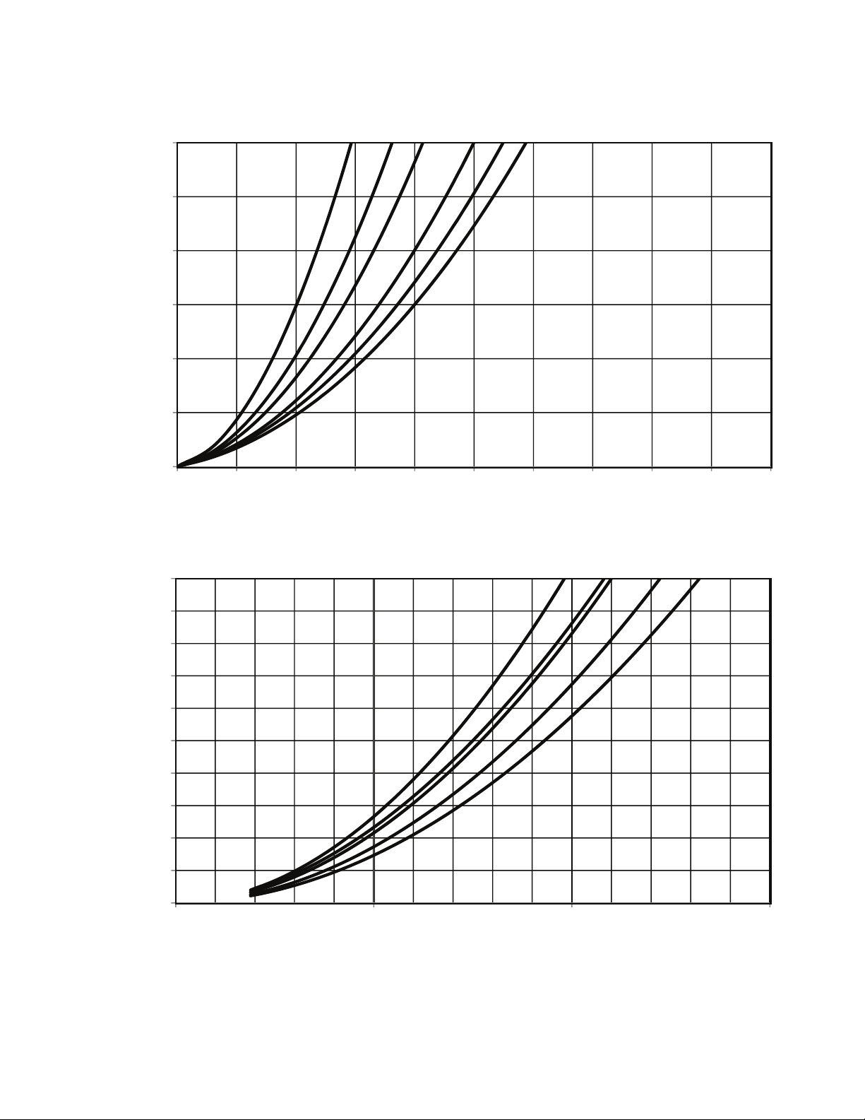
APPENDIX A (cont)
0
25
50
75
100
125
150
0123 45678 910
WATER PRESSURE DROP (kPa)
123 456
LITERS/SECOND
LEGEND
1 — 30RAP010,011 4 — 30RAP020 7 — 30RAP035 10 — 30RAP050
2 — 30RAP015 5 — 30RAP025 8 — 30RAP040 11 — 30RAP055
3 — 30RAP016,018 6 — 30RAP030 9 — 30RAP045 12 — 30RAP060
UNITS WITH SINGLE PUMP HYDRONIC PACKAGE (cont)
NOTES:
1. Pressure drop curves are suitable for water only.
2. Includes strainer and unit piping.
0
25
50
75
100
125
150
175
200
225
250
510150
WATER PRESSURE DROP (kPa)
7 8 9 10 11&12
LITERS/SECOND
Unit Pressure Drop Curves, 30RAP010-060 (SI)
77
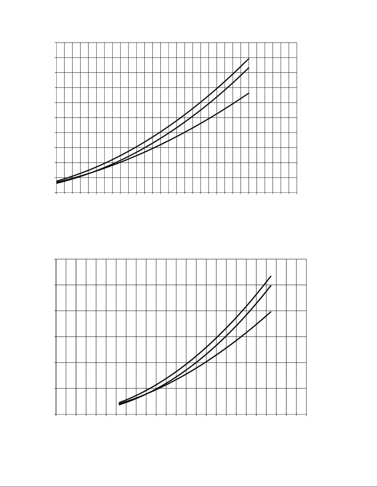
APPENDIX A (cont)
20
30
40
50
60
70
80
90
100
0
10
20
100 150 200 250 300 350 400
GPM
WATER PRESSURE DROP (ft)
1
2
3
LEGEND
1 — 30RAP070
2 — 30RAP080
3 — 30RAP090
a30-5352
NOTES:
1. Use the following formula to convert feet of water to psig:
ft of water (.4335) = psig
2. Use the following formula to convert psig to feet of water:
psig (2.306) = ft of water
3. Pressure drop curves are suitable for water only.
4. Includes strainer and unit piping.
100
150
200
250
300
0
50
0 5 10 15 20 25
1
2
3
LITERS/SECOND
WATER PRESSURE DROP (kPa)
LEGEND
1 — 30RAP070
2 — 30RAP080
3 — 30RAP090
a30-5353
NOTES:
1. Pressure drop curves are suitable for water only.
2. Includes strainer and unit piping.
UNITS WITH SINGLE PUMP HYDRONIC PACKAGE (cont)
Unit Pressure Drop Curves, 30RAP070-090 (English)
Unit Pressure Drop Curves, 30RAP070-090 (SI)
78

APPENDIX A (cont)
20
30
40
50
60
70
80
90
100
0
10
20
150
200
250
350
400
450
500
GPM
WATER PRESSURE DROP (ft wg)
1
2
3
300
4
LEGEND
1 — 30RAP100
2 — 30RAP115
3 — 30RAP130
4 — 30RAP150
a30-5446
NOTES:
1. Use the following formula to convert feet of water to psig:
ft of water (.4335) = psig
2. Use the following formula to convert psig to feet of water:
psig (2.306) = ft of water
3. Pressure drop curves are suitable for water only.
4. Includes strainer and unit piping.
1
2
3
4
100
150
200
250
300
0
50
WATER PRESSURE DROP (kPa)
5
10 15 20 25 30
LITERS/SECOND
35
LEGEND
1 — 30RAP100
2 — 30RAP115
3 — 30RAP130
4 — 30RAP150
a30-5448
NOTES:
1. Pressure drop curves are suitable for water only.
2. Includes strainer and unit piping.
Unit Pressure Drop Curves, 30RAP100-150 (English)
Unit Pressure Drop Curves, 30RAP100-150 (SI)
UNITS WITH SINGLE PUMP HYDRONIC PACKAGE (cont)
79

APPENDIX A (cont)
0
5
10
15
20
25
30
35
40
45
50
0102030405060708090100
WATER PRESSURE DROP (ft wg)
1
2
3 456
GPM
LEGEND
1 — 30RAP010,011 4 — 30RAP020 7 — 30RAP035 10 — 30RAP050
2 — 30RAP015 5 — 30RAP025 8 — 30RAP040 11 — 30RAP055
3 — 30RAP016,018 6 — 30RAP030 9 — 30RAP045 12 — 30RAP060
UNITS WITH DUAL PUMP HYDRONIC PACKAGE
NOTES:
1. Use the following formula to convert feet of water to psig:
ft of water (.4335) = psig
2. Use the following formula to convert psig to feet of water:
psig (2.306) = ft of water
3. Pressure drop curves are suitable for water only.
4. Includes strainer and unit piping.
Unit Pressure Drop Curves, 30RAP010-060 (English)
WATER PRESSURE DROP (ft wg)
120
7 8 9 10 11&12
100
80
60
40
20
0
0 50 100 150 200 250
GPM
80

APPENDIX A (cont)
a30-5136a
0
25
50
75
100
125
150
0123 45678 910
WATER PRESSURE DROP (kPa)
123 456
LITERS/SECOND
LEGEND
1 — 30RAP010,011 4 — 30RAP020 7 — 30RAP035 10 — 30RAP050
2 — 30RAP015 5 — 30RAP025 8 — 30RAP040 11 — 30RAP055
3 — 30RAP016,018 6 — 30RAP030 9 — 30RAP045 12 — 30RAP060
UNITS WITH DUAL PUMP HYDRONIC PACKAGE (cont)
a30-5137a
NOTES:
1. Pressure drop curves are suitable for water only.
2. Includes strainer and unit piping.
0
25
50
75
100
125
150
175
200
225
250
510150
WATER PRESSURE DROP (kPa)
7
8
9 10 11&12
LITERS/SECOND
Unit Pressure Drop Curves, 30RAP010-060 (SI)
81

APPENDIX A (cont)
30
40
50
60
70
80
90
0
10
20
100 150 200 250 300 350 400
GPM
WATER PRESSURE DROP (ft)
1
2
3
a30-5354
LEGEND
1 — 30RAP070
2 — 30RAP080
3 — 30RAP090
NOTES:
1. Use the following formula to convert feet of water to psig:
ft of water (.4335) = psig
2. Use the following formula to convert psig to feet of water:
psig (2.306) = ft of water
3. Pressure drop curves are suitable for water only.
4. Includes strainer and unit piping.
100
150
200
250
300
0
50
0 5 10 15 20
25
LITERS/SECOND
WATER PRESSURE DROP (kPa)
2
1
3
a30-5355
LEGEND
1 — 30RAP070
2 — 30RAP080
3 — 30RAP090
NOTES:
1. Pressure drop curves are suitable for water only.
2. Includes strainer and unit piping.
Unit Pressure Drop Curves, 30RAP070-090 (English)
Unit Pressure Drop Curves, 30RAP070-090 (SI)
UNITS WITH DUAL PUMP HYDRONIC PACKAGE (cont)
82

90
LEGEND
1 — 30RAP100
2 — 30RAP115
3 — 30RAP130
4 — 30RAP150
a30-5447
NOTES:
1. Use the following formula to convert feet of water to psig:
ft of water (.4335) = psig
2. Use the following formula to convert psig to feet of water:
psig (2.306) = ft of water
3. Pressure drop curves are suitable for water only.
4. Includes strainer and unit piping.
1
2
3
4
100
150
200
250
0
50
WATER PRESSURE DROP (kPa)
5
10 15 20 25
30
LITERS/SECOND
35
LEGEND
1 — 30RAP100
2 — 30RAP115
3 — 30RAP130
4 — 30RAP150
a30-5449
NOTES:
1. Pressure drop curves are suitable for water only.
2. Includes strainer and unit piping.
APPENDIX A (cont)
Unit Pressure Drop Curves, 30RAP100-150 (English)
80
70
60
50
40
30
20
WATER PRESSURE DROP (ft wg)
10
0
150
200
250
300
350 400 450
1
2
3
4
500
GPM
Unit Pressure Drop Curves, 30RAP100-150 (SI)
UNITS WITH DUAL PUMP HYDRONIC PACKAGE (cont)
83
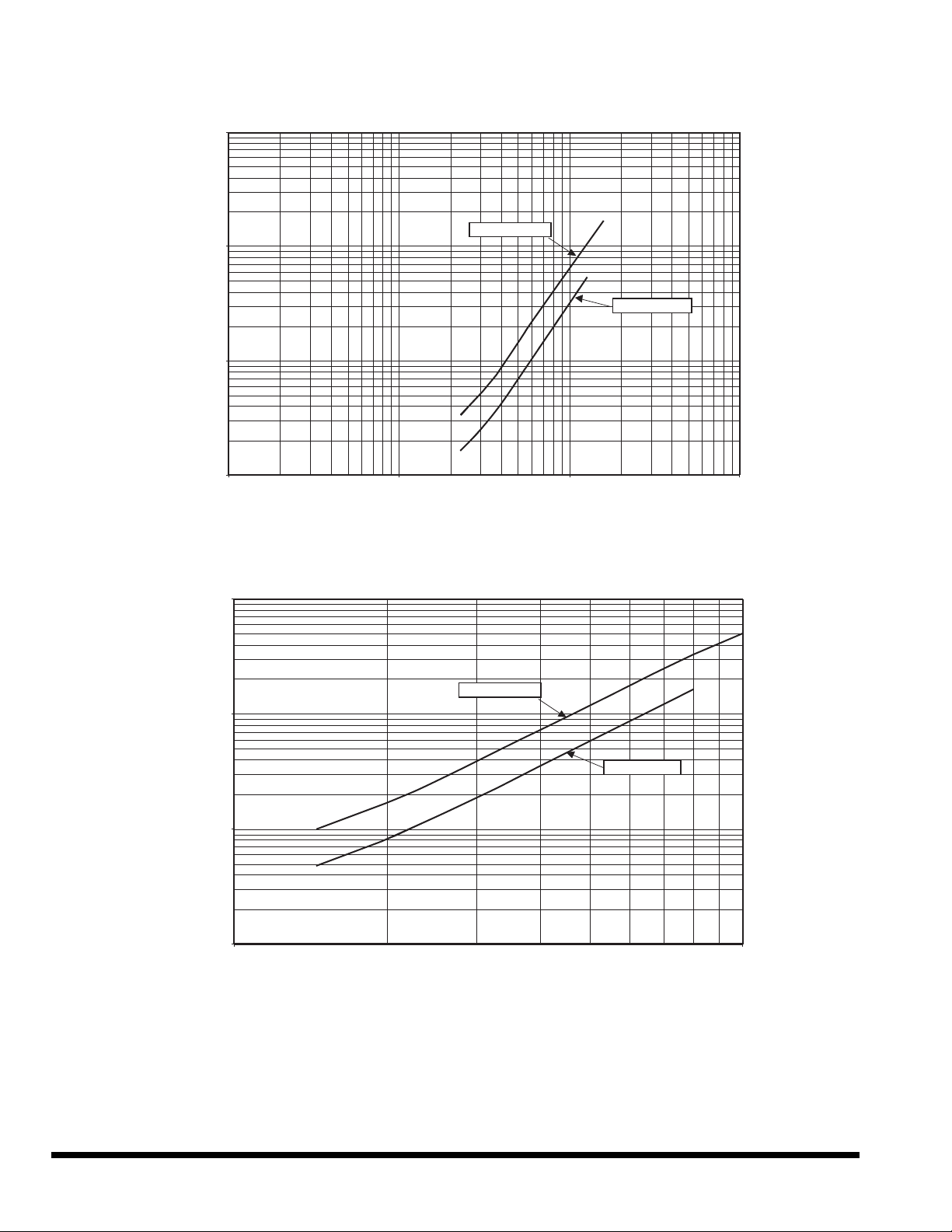
APPENDIX A (cont)
1
ACCESSORY TANK FLOW RATE (gpm)
PRESSURE DROP (ft wg)
30RAP035-060
30RAP010-030
100.0
10.0
1.0
0.1
10
100 1000
0.1
1.0
10.0
1.0 10.0
ACCESSORY TANK FLOW RATE (L/s)
PRESSURE DROP (kPa)
30RAP035-060
30RAP010-030
100.0
Pressure Drop Curves, Accessory Storage Tanks
© Carrier Corporation 2016
Manufacturer reserves the right to discontinue, or change at any time, specifications or designs without notice and without incurring obligations.
Catalog No. 04-53300163-01 Printed in U.S.A. Form 30RAP-16SI Pg 84 4-16 Replaces: 30RAP-13SI
 Loading...