

Page 1
Product
Data
AQUASNAP
®
30RA010-055
Air-Cooled Chillers
10 to 55 Nominal Tons
(25 to 200 kW)
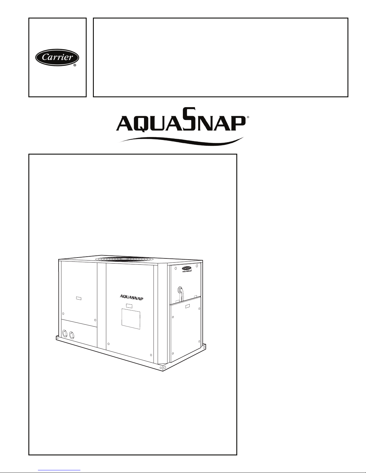
The AquaSnap chiller is an effective allin-one package that is easy to install
and easy to own. AquaSnap chillers
cost less to purchase and install, and
operate quietly and efficiently. Valueadded features include:
• Scroll compression
• Low profile construction
• Quiet AeroAcoustic™ fan system
• Easy to use ComfortLink™ controls
• Integrated hydronic pump package
• Accessory fluid storage tank
Features/Benefits
Carrier’s superior chiller
design provides savings at
initial purchase, at installation, and for years afterward.
Costs less right from the start
Only Carrier’s AquaSnap chillers feature a compact, all-in-one package design that installs quickly and easily on
the ground or the rooftop. The optional pump and hydronic components are
already built in; this costs less than buying and installing the components individually. The chiller’s fully integrated
and pre-assembled hydronic system installs in minutes. No other chiller in
this class installs so easily and inexpensively. The preassembled and integrated hydronic module utilizes top-quality
components and pumps to ensure
years of reliable operation. Use of the
optional fluid storage tank reduces installation costs and ensures sufficient
fluid volume is available for close-coupled and process cooling applications.
The AquaSnap unit’s high efficiency
keeps costs down.
Copyright 2009 Carrier Corporation Form 30RA-5PD
Page 2

Features/Benefits (cont)
AquaSnap® chillers make
noise in the marketplace, not
the workplace.
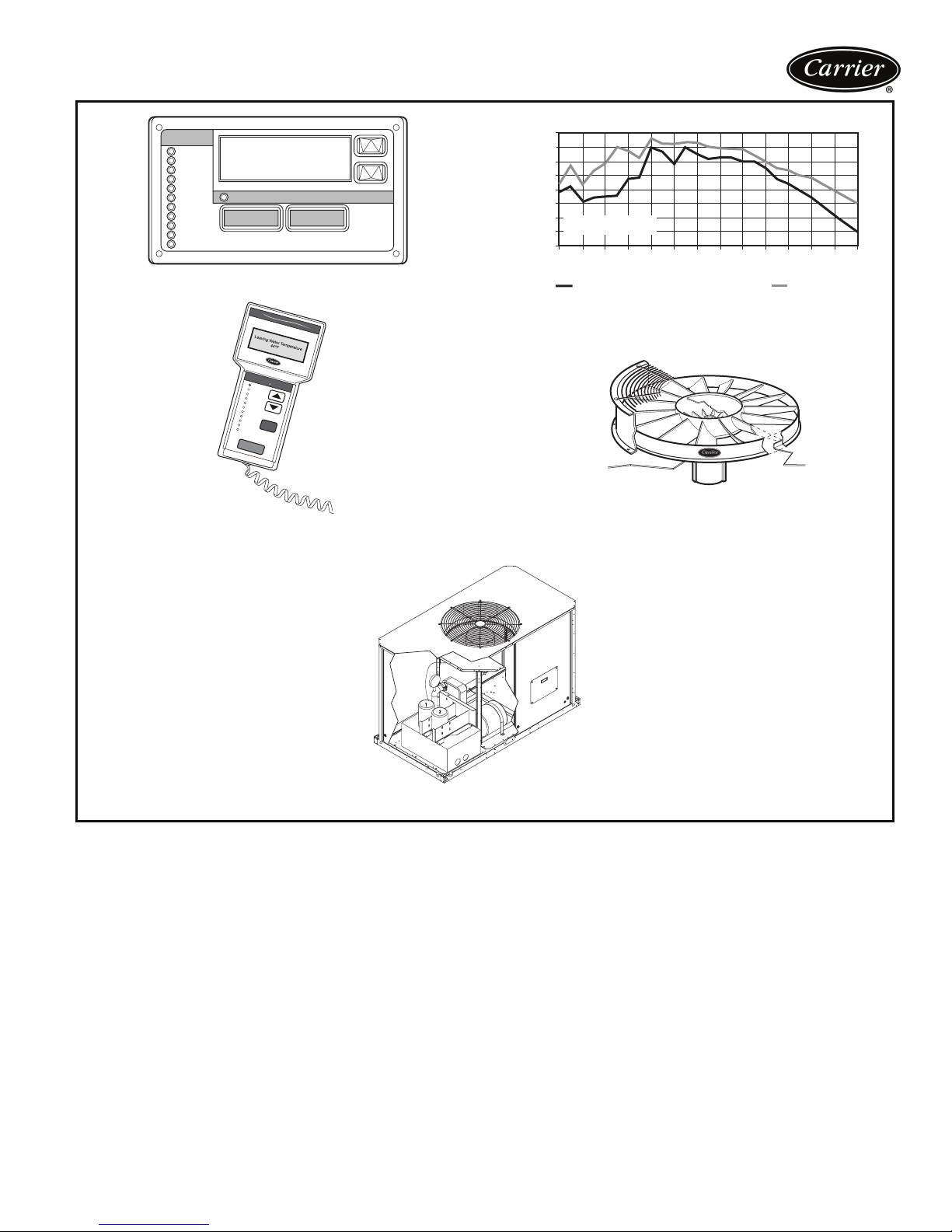
The AquaSnap chiller’s AeroAcoustic™ fan is almost twice as quiet as the
competition’s per cfm, which makes
AquaSnap chillers ideal for soundsensitive environments. When lower
ambient temperatures allow part-load
operation or during scheduled nighttime operation, the units operate with
fewer fans and become even quieter.
AquaSnap chillers are quiet during the
day and even quieter at night.
The fan is mounted to an extremely
rigid tower, which further reduces
vibrations and noise by preventing
them from being amplified through the
unit’s casing.
The savings will continue to
mount
Besides costing less to buy and install,
AquaSnap chillers are also more affordable to operate. They are very efficient air-cooled models, with full-load
EER (Energy Efficiency Ratio) up to
10.1. AquaSnap chillers use ultraquiet,
high-efficiency scroll compressors, operated in tandem for greater efficiency
at partial loads.
Proven reliability that’s built in
Thousands of AquaSnap chillers are
already in service around the world.
This field-proven design is backed by a
12-month warranty that includes the
hydronic system. The compressors are
maintenance-free and protected by an
auto-adaptive control that minimizes
compressor wear. Unit sizes 035 and
up have two independent refrigerant
circuits. Year-round operation is
standard, from –20 F (–29 C) (with
optional cooler heater and low ambient
control) to 125 F (52 C).
ComfortLinkTM controls speak
your language
The ComfortLink controls communicate in plain English, making it as easy
as possible to monitor and control
each AquaSnap chiller while accurately
maintaining fluid temperatures. The
large scrolling marquee display acts as
a window into the unit’s operation,
providing easy-to-read information
about chiller performance and over
15 diagnostic functions. Carrier 30
Series chillers’ ComfortLink controls
provide features such as chilled water
temperature reset, demand limiting,
compressor wear minimization and
protection, temperature and pressure
displays and diagnostic functions.
These controls result in higher chiller
reliability, simplified training and more
productive service calls with correspondingly lower operational and
maintenance costs.
Carrier’s exclusive handheld
Navigator™ display provides convenience and powerful information in the
palm of your hand. The Navigator
display helps technicians to quickly
diagnose problems and even prevent
them from occurring.
All AquaSnap units are ready to
be used with the Carrier Comfort
Network
®
(CCN) system.
AquaSnap units minimize the
impact on your roofline, as
well as your bottom line
The AquaSnap chiller’s low profile —
all models are just 4'-4" (1321 mm)
high — means it will not stand out if installed on the roof. The other dimensions are equally compact. The integrated hydronics and the chilled fluid
storage tank’s placement under the
chiller further minimize the footprint,
allowing easy installation almost anywhere.
2
Page 3
MODE
Run Status
Service Test
Temperature
Pressures
Setpoints
Inputs
Outputs
Configuration
Time Clock
Operating Modes
Alarms
Alarm Status
ESCAPE
ENTER
SCROLLING MARQUEE DISPLAY
Comfort
Link
MODE
Alarm
Run Status
S
tatus
Service Test
Temperatures
Pressures
Setpoints
Inputs
Outputs
Configuration
Tim
e Clock
ESC
Operating Modes
Alarms
ENTER
NAVIGATOR™ DISPLAY MODULE
90
85
80
75
70
65
60
PENETRATES BUILDING
STRUCTURE
55
SOUND POWER [dB(A)]
50
25
40
130 168
63
400
250
630 1080
1600
2400
4000
1/3 OCTAVE BAND CENTER FREQUENCY (Hz)
AEROACOUSTIC™ FAN vs. PROPELLER FAN
AEROACOUSTIC FAN
PROPELLER FAN
AEROACOUSTIC FAN VS PROPELLER FAN
LOW-NOISE AEROACOUSTIC FAN
WITH NIGHTTIME LOW SOUND
6300
8000
Table of contents
Features/Benefits . . . . . . . . . . . . . . . . . . . . . . . . . . . . . . . . . . . . . . . . . . .1-3
Model Number Nomenclature . . . . . . . . . . . . . . . . . . . . . . . . . . . . . . . . . . . 4
ARI Capacity Ratings . . . . . . . . . . . . . . . . . . . . . . . . . . . . . . . . . . . . . . . . . 4
Physical Data . . . . . . . . . . . . . . . . . . . . . . . . . . . . . . . . . . . . . . . . . . . . . .5-7
Options and Accessories . . . . . . . . . . . . . . . . . . . . . . . . . . . . . . . . . . . . . .8,9
Dimensions . . . . . . . . . . . . . . . . . . . . . . . . . . . . . . . . . . . . . . . . . . . . .10-18
Selection Procedure . . . . . . . . . . . . . . . . . . . . . . . . . . . . . . . . . . . . . . .19-25
Performance Data . . . . . . . . . . . . . . . . . . . . . . . . . . . . . . . . . . . . . . . .26,27
Typical Piping and Wiring . . . . . . . . . . . . . . . . . . . . . . . . . . . . . . . . . . .28,29
Electrical Data . . . . . . . . . . . . . . . . . . . . . . . . . . . . . . . . . . . . . . . . . . .30-32
Controls . . . . . . . . . . . . . . . . . . . . . . . . . . . . . . . . . . . . . . . . . . . . . . .33,34
Typical Control Wiring Schematic . . . . . . . . . . . . . . . . . . . . . . . . . . . . .35-37
Application Data . . . . . . . . . . . . . . . . . . . . . . . . . . . . . . . . . . . . . . . . .38-43
Guide Specifications . . . . . . . . . . . . . . . . . . . . . . . . . . . . . . . . . . . . . . .44-48
OPTIONAL HYDRONIC PACKAGE
Page
3
Page 4
Model number nomenclature
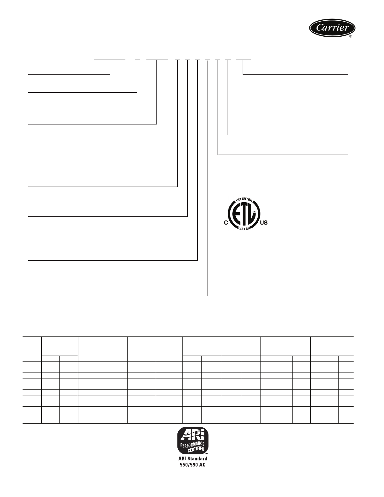
AQUASNAP® CHILLER MODEL NUMBER DESIGNATION
3 0 R A N 0 1 0 – – – 6 1 1 – –
38RA – Air-Cooled AquaSnap Chiller
Compressor Start Option
N– Standard Across-the-Line Start
Unit Sizes
010 025
015 030
018
022
Chilled Fluid Pump Options
–– No pump installed
A–Single Pump, 1.5 HP
B–Single Pump, 2 HP
C – Single Pump, 2 HP High Head
D–Single Pump, 3 HP
E–Single Pump, 5 HP
F–Dual Pump, 1.5 HP
G–Dual Pump, 2 HP
H–Dual Pump, 2 HP High Head
J–Dual Pump, 3 HP
K–Dual Pump, 5 HP
Display, Energy Management, GFI Option
––Standard Scrolling Marquee (SM) Display
E–SM + EMM
S – SM + EMM + GFI Convenience Outlet
Condenser Coil Options
––Standard Copper Tube/Aluminum Fin
C– Copper Tube/Copper Fin, Copper Tube Sheet/Mylar
E–Copper Tube/Aluminum Fin with E-Coat
F–Copper Tube/Copper Fin, Copper Tube Sheet,
K– Copper Tube/Aluminum Fin Precoated
045
050
035
055
040
(120 Volt, 4 Amp) [1,4,5,6 Voltages Only)
Coil Separator
Mylar Sep
arator with E-Coat
Factory-Installed Options (FIOP)
Packaging
1 – Standard Domestic (Coil Cover and
Bottom Skid)
3 – Standard Export with Coil Cover,
Top and Bottom Skid & Shipping Bag
4–Full Export Crate
5–Option #1 with Factory-Installed Coil Grilles
7–Option #
8 – Option #4 with Factory-Installed Coil Grilles
Series – 1
3 with Factory-Installed Coil Grilles
LEGEND
EMM — Energy Management Module
GFI — Ground Fault Interrupting
Quality Assurance
Voltage
1–575-3-60
2–380-3-60
4–230-3-60
5–208/230-3-60
6–460-3-60
Certified to ISO 9001: 2000
a30-4595
ARI* capacity ratings
UNIT
30RA
010 9.6 33.7 9.7 1.9 11.7 9.8 2.9 12.9 3.8 22.9 1.4 5.6 16.7
015 13.7 48.1 14.8 1.9 16.8 9.8 2.9 12.8 3.7 33.0 2.1 6.8 20.3
018 15.9 55.9 18.0 1.9 20.0 9.6 2.8 13.4 3.9 38.2 2.4 7.5 22.4
022 21.1 74.2 23.4 1.7 25.2 10.0 2.9 14.1 4.1 50.6 3.2 9.7 29.0
025 23.8 83.6 27.9 1.7 29.7 9.6 2.8 13.9 4.1 57.1 3.6 10.7 32.0
030 27.2 95.6 31.7 1.7 33.5 9.8 2.9 14.0 4.1 65.3 4.1 12.6 37.7
035 34.8 122.3 37.8 3.6 41.5 10.1 2.9 14.5 4.2 83.4 5.3 7.7 23.0
040 37.7 132.5 42.8 3.6 46.6 9.7 2.8 13.6 4.0 90.6 5.7 8.2 24.5
045 43.1 151.5 47.5 3.4 51.1 10.1 3.0 15.2 4.4 103.4 6.5 11.2 33.5
050 47.4 166.6 55.8 3.4 59.4 9.6 2.8 14.1 4.1 113.8 7.2 12.1 36.2
055 54.3 190.8 63.4 3.4 67.0 9.7 2.8 14.1 4.1 130.4 8.2 14.3 42.7
LEGEND
COP — Coefficient of Performance
EER — Energy Efficiency Ratio
IPLV — Integrated Part Load Value
* Air Conditioning and Refrigeration Institute.
NOTE: Based on ARI-550/590 standard rating conditions. Ratings are for
standard chillers only. Ratings do not include options.
CAPACITY
Tons kW EER COP EER COP GPM L/s Ft wg kPa
COMPRESSOR
POWER INPUT
(kW)
FAN
POWER
(kW)
TOTAL
POWER
(kW)
FULL LOAD IPLV
COOLER FLOW
RATE
COOLER
WATER
PRESSURE
DROP
4
Page 5
Physical data
ENGLISH
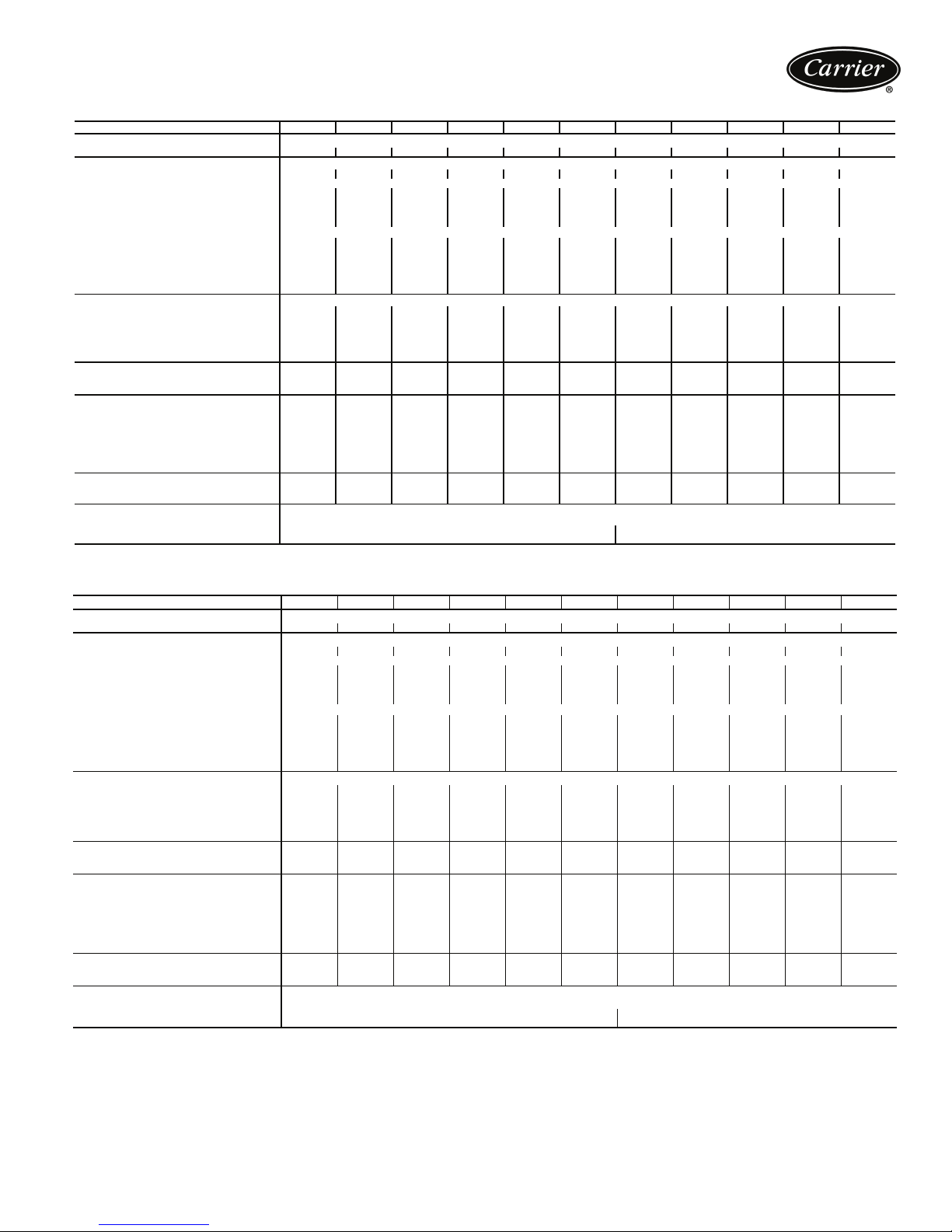
UNIT 30RA 010 015 018 022 025 030 035 040 045 050 055
REFRIGERANT TYPE R-22, TXV Controlled System
Refrigerant Charge (lb) Ckt A/Ckt B 16/— 24/— 31/— 40/— 45/— 55/— 44/30 45/30 44/44 45/45 55/55
COMPRESSORS Scroll, Hermetic
Quantity 11222233444
Speed (Rpm) 3500
(Qty) Ckt A
(Qty) Ckt B
Oil Charge (Compressor/Pt) SM110/5.7, SM115/6.7, SM125/6.7, SM160/7.0, SM185/11.6
No. Capacity Steps
Standard 11222233444
Optional (Maximum) 22333344555
Minimum Capacity Step (%)
Standard 100 100 50 41 50 50 25 32 22 25 25
Optional 69 79 32 27 38 39 16 24 15 19 20
COOLER Welded, Direct-Expansion Plate Heat Exchanger
Net Fluid Volume (gal) 1.12 1.61 1.86 2.41 2.84 3.40 6.30 7.00 6.55 7.44 8.56
Maximum Refrigerant Pressure (psig) 450 450 450 450 450 450 450 450 450 450 450
Maximum Water Side Pressure
Without Pump(s) (psig)
Maximum Water Side Pressure
With Pump(s) (psig)
WATER CONNECTIONS (in.)
Inlet and Outlet, FPT 2222222
Drain (NPT)
CONDENSER FANS
Standard Low Noise Type
Fan Speed (Rpm) Standard/Low Noise 1140/570 1140/570 1140/570 —/850 —/850 —/850 —/850 —/850 —/850 —/850 —/850
No. Blades...Diameter (in.) Ckt A/Ckt B
(1) SM125 (1) SM185 (2) SM110
——————(1) SM185(1) SM185
150 150 150 150 150 150 150 150 150 150 150
150 150 150 150 150 150 150 150 150 150 150
1
/
2
1
/
2
15...30/— 15...30/— 15...30/— 11...30/— 11...30/— 11...30/—
No. Fans...Total kW 1...1.8 1...1.8 1...1.8 2...2.0 2...2.0 2...2.0
Total Airflow (Cfm) 10,500 10,500 10,500 13,600 13,600 14,500 21,000 21,000 27,300 27,300 29,000
CONDENSER COILS
Quantity...No. Rows 1...2 1...3 1...3 1...3 1...3 1...3 2...3 2...3 2...3 2...3 2...3
Total Face Area (sq ft) 23 23 23 32 32 40 55 55 64 64 80
HYDRONIC MODULE (Optional)* Pump(s), Strainer with Blowdown Valve, Expansion Tank, Pressure Taps, Drain and Vent Plugs, Flow Switch, and Balance Valve
Pump Single or Dual, Centrifugal Monocell Pump(s), 3500 Rpm
Expansion Tank Volume (gal)
Total/Acceptance 5.0/2.9 10.0/5.5
(1) SM115,
(1) SM160
1
/
2
(2) SM160 (2) SM185
1
/
2
1
/
2
(1) SM115,
(1) SM160
1
/
2
11...30/
11...30
2...2.0 (A),
1...1.8 (B)
(2) SM160
1
/
2
1
/
2
11...30/
11...30
2...2.0 (A),
1...1.8 (B)
(1) SM125,
(1) SM160
(1) SM125,
(1) SM160
21/
2
1
/
2
11...30/
11...30
(2) SM160 (2) SM185
(2) SM160 (2) SM185
21/
2
1
/
2
21/
1
/
2
11...30/
11...30
21/
2
1
/
2
11...30/
11...30
2
4...4.0 4...4.0 4...4.0
SI
UNIT 30RA 010 015 018 022 025 030 035 040 045 050 055
REFRIGERANT TYPE R-22, TXV Controlled System
Refrigerant Charge (kg) Ckt A/Ckt B 7.3/— 10.9/— 14.1/— 18.2/— 20.5/— 22.7/— 20.0/13.6 20.4/13.6 20.0/20.0 20.4/20.4 25.0/25.0
COMPRESSORS Scroll, Hermetic
Quantity 11222233444
Speed (r/s) 58.3
(Qty) Ckt A
(Qty) Ckt B
Oil Charge (Compressor/Pt) SM110/5.7, SM115/6.7, SM125/6.7, SM160/7.0, SM185/11.6
No. Capacity Steps
Standard 11222233444
Optional (Maximum) 22333344555
Minimum Capacity Step (%)
Standard 100 100 50 42 50 50 25 32 22 25 25
Optional 69 79 32 27 38 39 16 24 15 19 20
COOLER Welded, Direct-Expansion Plate Heat Exchanger
Net Fluid Volume (L) 4.22 6.08 7.03 9.12 10.75 12.84 23.84 26.49 24.79 28.12 32.34
Maximum Refrigerant Pressure (kPa) 3103 3103 3103 3103 3103 3103 3103 3103 3103 3103 3103
Maximum Water Side Pressure
Without Pump(s) (kPa)
Maximum Water Side Pressure
With Pump(s) (kPa)
WATER CONNECTIONS (mm)
Inlet and Outlet, FPT 50.8 50.8 50.8 50.8 50.8 50.8 63.5 63.5 63.5 63.5 63.5
Drain (NPT) 12.7 12.7 12.7 12.7 12.7 12.7 12.7 12.7 12.7 12.7 12.7
CONDENSER FANS
Standard Low Noise Type
Fan Speed (r/s) Standard/Low Noise 19/9.5 19/9.5 19/9.5 —/14.2 —/14.2 —/14.2 —/14.2 —/14.2 —/14.2 —/14.2 —/14.2
No. Blades...Diameter (mm) Ckt A/Ckt B
(1) SM125 (1) SM185 (2) SM 110
——————(1) SM185(1) SM185
1034 1034 1034 1034 1034 1034 1034 1034 1034 1034 1034
1034 1034 1034 1034 1034 1034 1034 1034 1034 1034 1034
15...762/— 15...762/— 15...762/— 11...762/— 11...762/— 11...762/—
No. Fans...Total kW 1...1.8 1...1.8 1...1.8 2...2.0 2...2.0 2...2.0
Total Airflow (L/s) 4,955 4,955 4,955 6,419 6,419 6,843 9,595 9,595 12,884 12,884 13,687
CONDENSER COILS
Quantity...No. Rows 1...2 1...3 1...3 1...3 1...3 1...3 2...3 2...3 2...3 2...3 2...3
Total Face Area (sq m) 2.14 2.14 2.14 2.97 2.97 3.72 5.11 5.11 5.95 5.95 7.43
HYDRONIC MODULE (Optional)* Pump(s), Strainer with Blowdown Valve, Expansion Tank, Pressure Taps, Drain and Vent Plugs, Flow Switch, and Balance Valve
Pump Single or Dual, Centrifugal Monocell Pump(s), 58.3 r/s
Expansion Tank Volume (L)
Total/Acceptance 18.9/11.0 37.9/20.8
(1) SM115,
(1) SM160
(2) SM160 (2) SM185
(1) SM115,
(1) SM160
11...762/
11...762
2...2.0 (A),
1...1.8 (B)
(2) SM160
11...762/
11...762
2...2.0 (A),
1...1.8 (B)
(1) SM125,
(1) SM160
(1) SM125,
(1) SM160
11...762/
11...762
(2) SM160 (2) SM185
(2) SM160 (2) SM185
11...762/
11...762
4...4.0 4...4.0 4...4.0
11...762/
11...762
LEGEND
TXV — Thermostatic Expansion Valve
*Flow switch and strainer are standard on all units, with or without hydronic package.
5
Page 6
Physical data (cont)
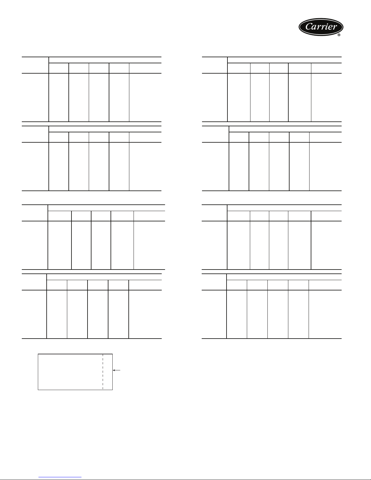
UNIT WEIGHTS
STD UNITS
30RA
SIZE
010 182 210 255 299 946 010 194 231 274 326 1025
015 197 245 291 335 1068 015 216 280 321 382 1199
018 206 268 377 358 1209 018 220 303 411 404 1338
022 336 451 381 355 1523 022 364 521 418 410 1713
025 350 464 395 380 1589 025 380 532 432 436 1780
030 378 518 409 400 1705 030 409 606 441 474 1930
035 748 642 604 850 2844 035 854 721 691 958 3224
040 763 653 616 882 2914 040 869 731 702 992 3294
045 860 709 746 903 3218 045 965 790 833 1011 3599
050 876 721 770 946 3313 050 978 805 859 1051 3693
055 977 753 831 954 3515 055 1096 857 931 1082 3966
30RA
SIZE
010 83 95 116 136 430 010 88 105 124 148 465
015 89 111 132 152 484 015 98 127 146 173 544
018 93 122 171 162 548 018 100 137 186 183 606
022 152 205 173 161 691 022 165 236 190 186 777
025 159 210 179 172 720 025 172 241 196 198 807
030 171 235 186 181 773 030 186 275 200 215 876
035 339 291 274 386 1290 035 387 327 313 435 1462
040 346 296 279 400 1321 040 394 332 318 450 1494
045
050 397 327 349 429 1502 050 444 365 390 477 1676
055 443 342 377 433 1595 055 497 389 422 491 1799
ABCD
ABCD
390 322 338 410 1460 045 438 358 378 459 1633
POUNDS — ALUMINUM
KILOGRAMS — ALUMINUM
Tot al
Weight
Tot al
Weight
30RA
SIZE
30RA
SIZE
ABCD
ABCD
SINGLE PUMP UNITS
30RA
SIZE
010 209 241 293 343 1086 010 221 262 312 370 1165
015 223 277 329 379 1208 015 242 312 359 426 1339
018 230 299 421 399 1349 018 244 334 455 445 1478
022 367 492 416 388 1663 022 395 562 453 443 1853
025 381 505 430 413 1729 025 411 573 467 469 1920
030 409 561 443 433 1845 030 440 649 475 507 2070
035 801 687 646 910 3044 035 907 766 733 1018 3424
040 815 698 658 943 3114 040 921 776 744 1053 3494
045 913 753 792 959 3418 045 1018 834 879 1067 3799
050 929 765 816 1003 3513 050 1031 849 905 1108 3893
055 1033 796 878 1008 3715 055 1152 900 978 1136 4166
30RA
SIZE
010 95 109 133 156 493 010 108 129 152 181 570
015 101 126 149 172 548 015 117 151 174 206 648
018 104 136 191 181 612 018 117 161 218 215 711
022 166 224 189 176 755 022 187 268 215 211 881
025 173 229 195 187 784 025 194 272 221 224 911
030 185 254 201 196 836
035 363 311 293 413 1380 035 422 356 341 474 1593
040 370 316 298 427 1411 040 429 361 346 490 1626
045 414 342 359 435 1550 045 473 387 408 496 1764
050 421 347 370 455 1593 050 479 394 421 514 1808
055 468 361 398 458 1685 055 533 417 453 527 1930
ABCD
ABCD
POUNDS — ALUMINUM
KILOGRAMS — ALUMINUM
Tot al
Weight
Tot al
Weight
30RA
SIZE
30RA
SIZE
030 208 308 224 241 981
ABCD
ABCD
POUNDS — COPPER
KILOGRAMS — COPPER
POUNDS — COPPER
KILOGRAMS — COPPER
Tot al
Weigh t
Tot al
Weight
Tot al
Weight
Tot al
Weight
B
C
A
D
CONTROL
BOX END
6
a30-4596
Page 7
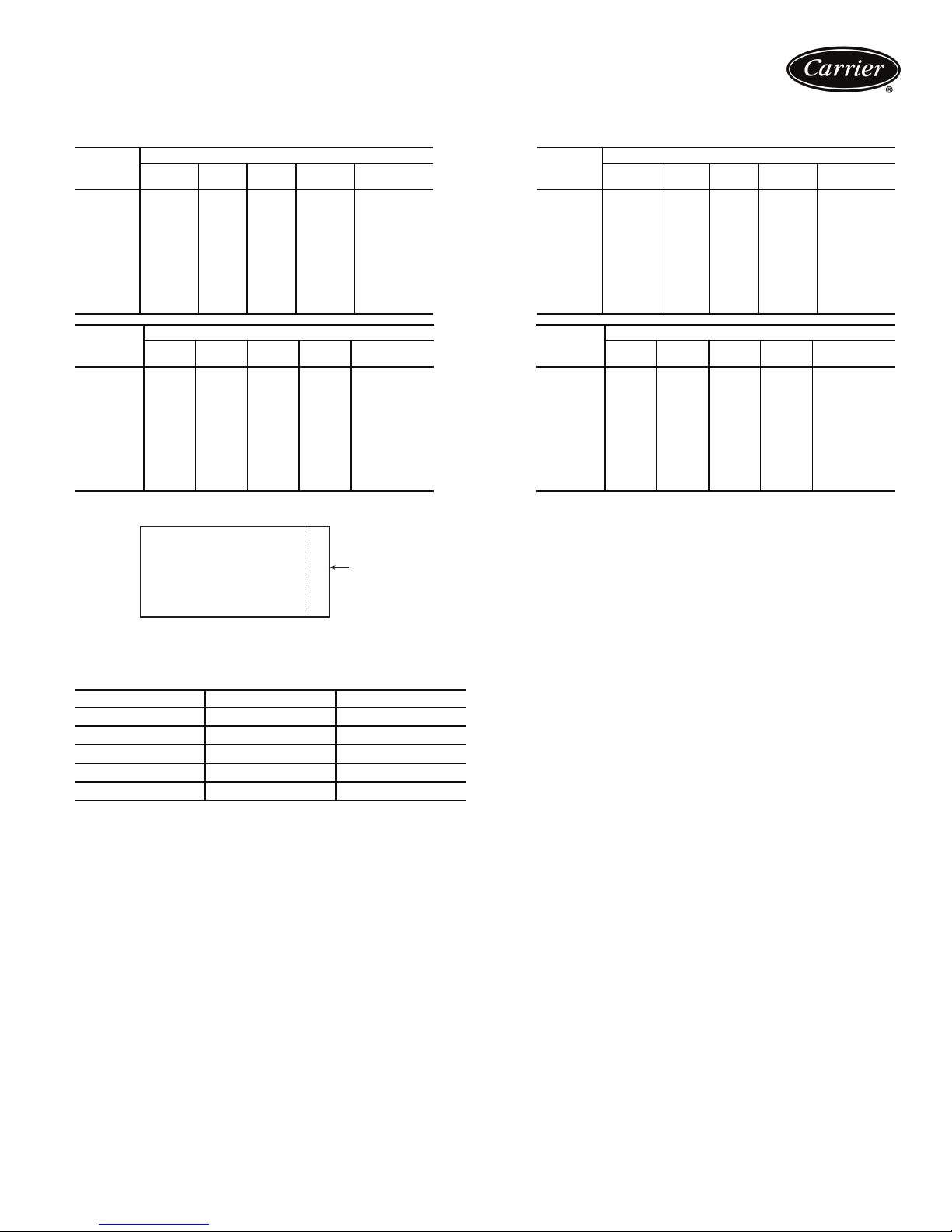
UNIT WEIGHTS (cont)
DUAL PUMP UNITS
30RA
SIZE
010 226 262 316 372 1176 010 238 283 335 399 1255
015 238 299 353 408 1298 015 257 334 383 455 1429
018 244 320 448 427 1439 018 258 355 482 473 1568
022 385 521 437 410 1753 022 413 591 474 465 1943
025 399 533 451 436 1819 025 429 601 488 492 2010
030 427 590 462 456 1935 030 458 678 494 530 2160
035 825 707 666 936 3134 035 931 786 753 1044 3514
040 840 717 678 969 3204 040 946 795 764 1079 3584
045 938 773 813 984 3508 045 1043 854 900 1092 3889
050 953 784 837 1029 3603 050 1055 868 926 1134 3983
055 1057 816 899 1033 3805 055 1176 920 999 1161 4256
30RA
SIZE
010 103 119 144 169 535 010 108 129 152 181 570
015 108 135 160 185 588 015 117 151 174 206 648
018 110 146 203 194 653 018 117 161 218 215 711
022 174 237 198 186 795 022 187 268 215 211 881
025 181 241 204 198 824 025 194 272 221 224 911
030 193 268 210 207 878 030 208 308 224 241 981
035 374 320 302 425 1421 035 422 356 341 474 1593
040 381 325 307 440 1453 040 429 361 346 490 1626
045
050 432 356 380 466 1634 050 479 394 421 514 1808
055 479 370 408 469 1726 055 533 417 453 527 1930
ABCD
ABCD
425 351 368 447 1591 045 473 387 408 496 1764
POUNDS — ALUMINUM
KILOGRAMS — ALUMINUM
Tot al
Weight
Tot al
Weight
30RA
SIZE
30RA
SIZE
ABCD
ABCD
POUNDS — COPPER
KILOGRAMS — COPPER
Tot al
Weight
Tot al
Weigh t
B
C
A
D
CONTROL
BOX END
PUMP IMPELLER SIZES
PUMP OPTION PUMP DIAMETER (in.)
A,F
B,G 1
C,H
D,J 1
E,K 1
3
/4AAB 4.25
1
/4AAB 3.88
3
/4AAB 4.75
1
/4AAB 4.50
1
/2AAB 4.63
7
Page 8
Options and accessories
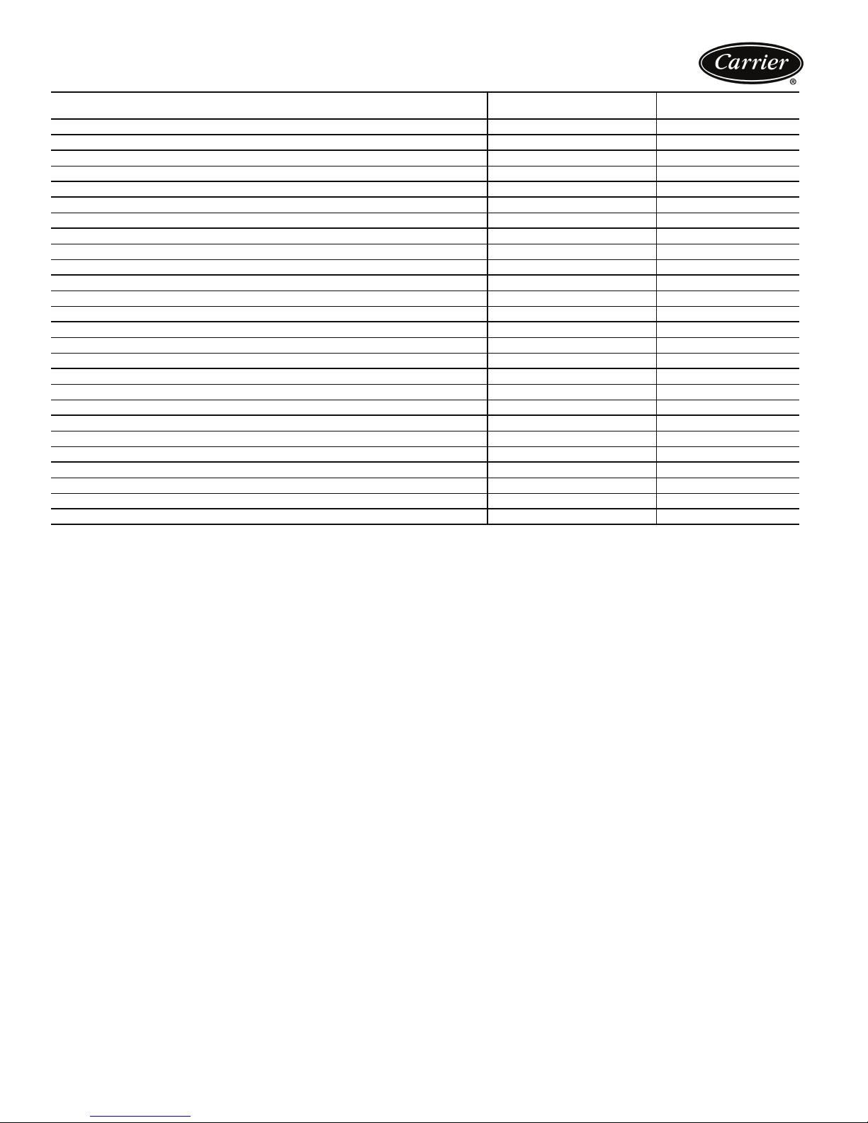
ITEM
Hydronic Pump Package X
Enviro-Shield™ System Condenser Coil Protection Options X
Copper Fins X
Aluminum Fins, E-coat X
Copper Fins, E-coat X
Aluminum Fins, Pre-coated X
Medium Temperature Brine, 15 F to 40 F LBT X
Non-Fused Disconnect X
Low-Ambient Protection Package (Cooler Heater) X
Motormaster® V Low-Ambient Control XX
Minimum Load Control XX
Security Grilles XX
Hail Guards X
Navigator™ Hand Held Display X
Control Display Access Door X
Remote Enhanced Display X
Chillervisor System Manager III Multi-Unit Control X
GFI Convenience Outlet XX
Energy Management Module (EMM) XX
Vibration Isolation X
Chilled Water Storage Tank X
Touch Pilot™ Display X
LON Translator Control X
BACnet™ Modbus Translator Control X
Liquid Line Solenoid Kit X
Wind Baffle Kit X
FACTORY-INSTALLED
OPTION
FIELD-INSTALLED
ACCESSORY
LEGEND
GFI —Ground Fault Interrupter
LBT—Leaving Brine Temperature
Factory-installed options
Hydronic pump package — This option adds circulat-
ing pumps, complete with controls, contactor, and insulated expansion tank. Available in single or dual (lead/lag
controlled) cooler pump versions, with total dynamic head
external to the chiller from approximately 15 to 75 feet.
Low ambient protection package — Cooler heaters
provide protection from cooler freeze-up to –20 F (–29 C).
Includes low ambient protection for optional hydronic
package, when provided.
Energy management module — This module provides
energy management capabilities to minimize chiller energy
consumption. Several features are provided with this module including leaving fluid temperature reset, cooling set
point reset or demand limit control from a 4 to 20 mA signal, 2-point demand limit control (from 0 to 100%) activated by a remote contact closure, and discrete input for
“Ice Done” indication for ice storage system interface.
GFI convenience outlet — The factory installed convenience outlet includes 4-amp GFI (ground fault interrupter) receptacle with independent fuse protection.
Convenience outlet is 115-v female receptacle.
Low-ambient Motormaster® V control — This option
permits operation of the 30RA units down to –20 F
(–29 C) outdoor ambient temperature. The control is also
available as a field-installed accessory. Also requires
field-installed wind baffles, minimum load control, and the
liquid line solenoid accessory.
Non-fused disconnect — This option provides nonfused disconnect capability for power and control located
at the unit.
Minimum load control — This option allows additional
capacity reduction for unit operation below the minimum
step of unloading (down to 15% of the minimum unit
capacity, depending on unit size). Minimum load control is
also available as a field-installed accessory.
Condenser coil options — These options are available
to match coil construction to the site conditions for the best
durability. Refer to the Environmental Corrosion Protection white paper for more information.
Security grilles — One-in. by four-in. coated wire grille
protects condenser coil from damage.
Medium temperature brine — This option permits
supply liquid temperatures to be set from 15 F (–9.4 C) to
40 F (4.4 C). Refrigeration circuit components, such as the
expansion device, are modified at the factory to adjust for
lower refrigerant flow rates. The use of this option also
requires the addition of the Motormaster V low ambient
control, field-installed wind baffles or accessory wind baffle
kit, minimum load control, and the accessory liquid line
solenoid.
8
Page 9
Field-installed accessories
Minimum load control — This option allows additional
capacity reduction for unit operation below the minimum
step of unloading (down to 15% of the minimum unit
capacity). Minimum load control is also available as a
factory-installed option.
Control display access door — This option provides
easy access to the unit control module through a
see-through door without having to open the control box
panels.
Navigator™ display module — Provides a portable,
hand held display module for convenient access to unit
status, operation, configuration and troubleshooting diagnostics capability. The 4-line, 80-character LCD display
provides clear language information in English, French,
Spanish or Portuguese. The weatherproof enclosure and
industrial grade extension cord makes the Navigator ideally
suited for outdoor applications. Magnets located on the
back of the module allow attachment of any sheet metal
component for hands free operation.
Remote enhanced display — This accessory kit contains a remotely mounted 40-character per line, 16-line
display panel for unit diagnostics.
Chillervisor System Manager III multi-unit control
— This accessory allows sequencing of between 2 and
8 chillers in parallel or 2 chillers in series. Pump control is
also provided.
Hail guards — Sheet metal hood provides protection
against hail and flying debris damage.
Security grilles — One-in. x 4-in. coated wire grille protects condenser coil from damage.
Low ambient Motormaster
trol — Permits starting and operating down to –20 F
(–29 C) outside ambient temperature. This control is also
available as a factory-installed option. Requires fieldinstalled wind baffles, minimum load control, and accessory liquid line solenoid.
Liquid line solenoid kit — The kit provides a liquid line
solenoid valve (per refrigerant circuit) which causes a
®
V head pressure con-
complete liquid line shutoff when the chiller is shut down.
This accessory is required when the medium temperature
brine option or the Motormaster V are used.
Wind baffle kit — This kit provides a factory designed
wind baffle for applications requiring protection. Fieldinstalled wind baffles are required when the Motormaster V
is used.
Energy management module — This module provides
energy management capabilities to minimize chiller energy
consumption. Several features are provided with this module including leaving fluid temperature reset, cooling set
point reset or demand limit control from a 4 to 20 mA
signal; 2-point demand limit control (from 0 to 100%)
activated by a remote contact closure; and discrete input
for “Ice Done” indication for ice storage system interface.
GFI convenience outlet — The field-installed convenience outlet includes 4-amp GFI (Ground Fault Interrupter) receptacle with independent fuse protection.
Convenience outlet is 115-v female receptacle.
Chilled water storage tank — Provides additional loop
volume for improved temperature control and chilled water
loop stability. Will provide up to 6 gallons per ton. Heater
supplied (additional 230-1-60 field power supply required)
to protect to –20 F (–29 C).
Vibration isolation — The field-installed
1
/4-in. neoprene isolator pads (24-in. x 3-in.) reduce vibration transmission from the compressor through the floor and into
the conditioned space.
BACnet translator control — The control provides an
interface between the chiller and a BACnet Local Area
Network (LAN, i.e., MS/TP EIA-485).
LON translator control — The control provides an
interface between the chiller and a Local Operating Network (LON, i.e., LonWorks FT-10A ANSI/EIA-709.1).
Touch Pilot™ display — The display, when used as an
accessory, is a cost-effective, touch-screen, remote-mount
device that can be used in lieu of the remote enhanced
display.
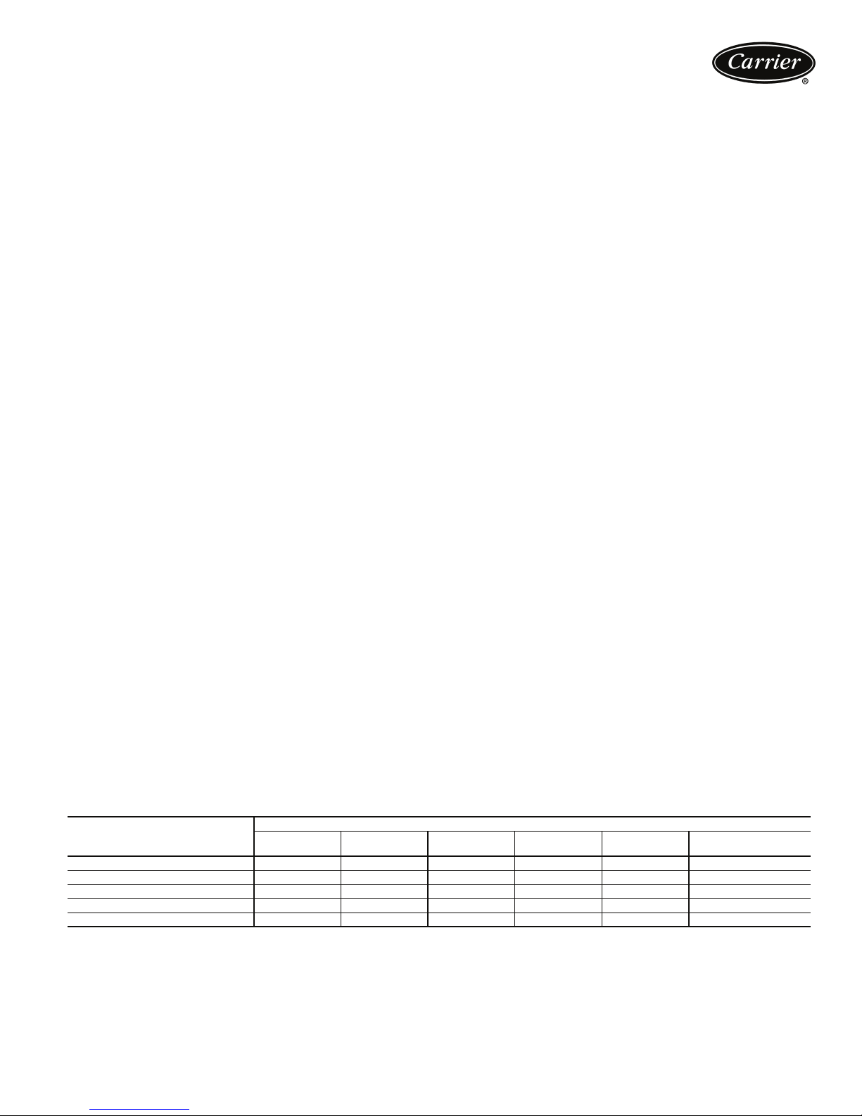
CONDENSER COIL CORROSION PROTECTION OPTIONS
ENVIRO-SHIELD™
OPTION*
AL Fins (Standard Coils) X
CU Fins XX
AL Fins, E-coat XX X
CU Fins, E-coat X
AL Fins, Precoated X
LEGEND
AL — Aluminum
CU — Copper
*See page 42 for further description, also see “Environmental Corrosion Protection” white paper for more information (Publication 04-581006-01).
Standard
Mild
Coastal
Moderate
Coastal
ENVIRONMENT
Severe
Coastal
Industrial
Combined
Industrial/Coastal
9
Page 10
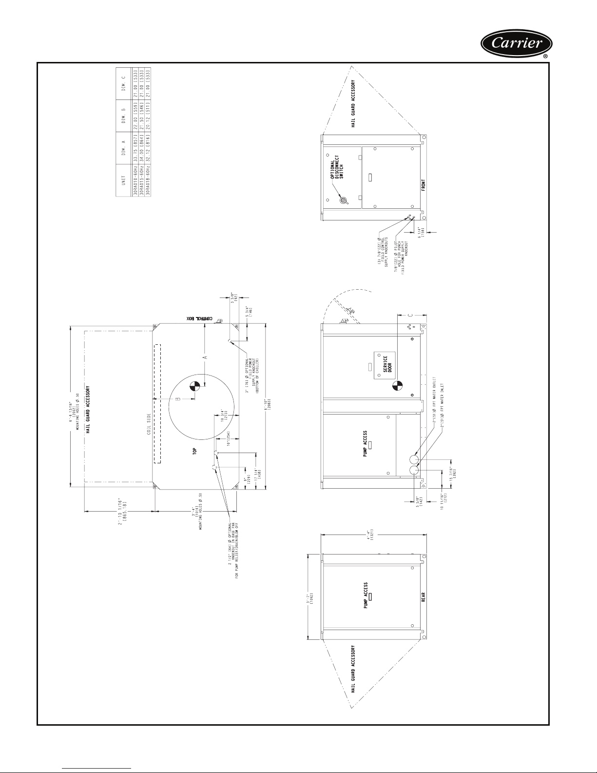
Dimensions — 30RA010,015,018
installed is 3 ft [914 mm] to outside edge of hail
guard top panel.
6 ft [1981 mm].
TOP — Do not restrict in any way
COIL SIDE — 3 1/2 ft [1067 mm] from solid surface
OTHER SIDE AND ENDS — 3 ft [914 mm] from
solid surface (for service access)
1. Unit must have clearances for airflow as follows:
NOTES:
2. Coil side clearance with accessory hail guard
entering fluid piping.
3. Coil side clearance for multiple chiller installation is
4. Flow switch and strainer are factory installed in
5. Dimensions in [ ] are in mm.
10
a30-4597
Page 11
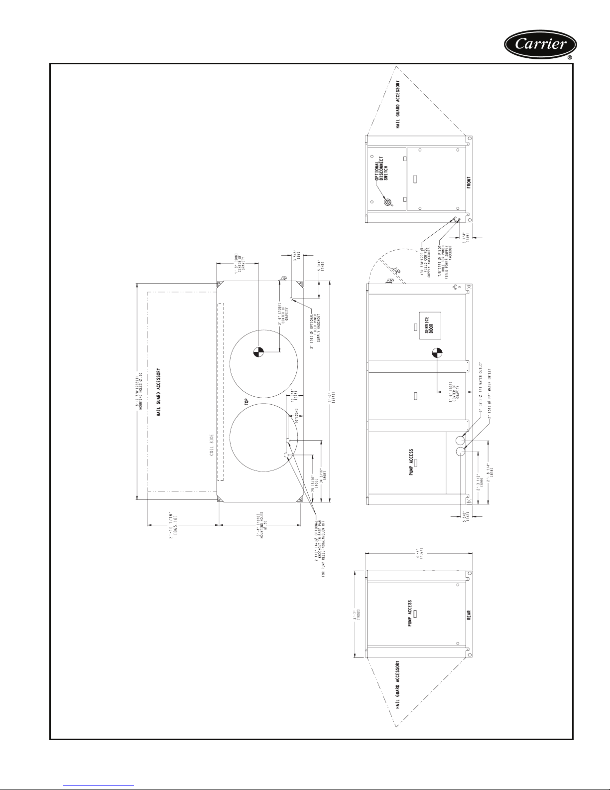
Dimensions — 30RA022,025
installed is 3 ft [914 mm] to outside edge of hail
guard top panel.
2. Coil side clearance with accessory hail guard
3. Coil side clearance for multiple chiller installation is
6 ft [1981 mm].
4. Flow switch and strainer are factory installed in
TOP — Do not restrict in any way
COIL SIDE — 3 1/2 ft [1067 mm] from solid surface
OTHER SIDE AND ENDS — 3 ft [914 mm] from
solid surface (for service access)
1. Unit must have clearances for airflow as follows:
NOTES:
entering fluid piping.
5. Dimensions in [ ] are in mm.
a30-4598
11
Page 12
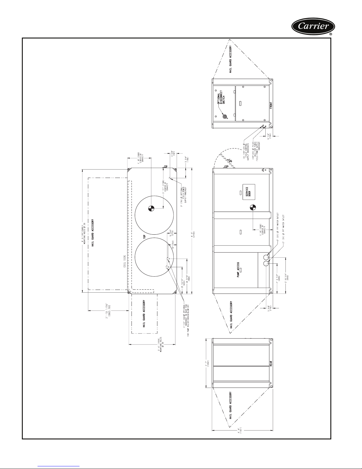
Dimensions — 30RA030
installed is 3 ft [914 mm] to outside edge of hail
guard top panel.
6 ft [1981 mm].
TOP — Do not restrict in any way
COIL SIDE — 3 1/2 ft [1067 mm] from solid surface
OTHER SIDE AND ENDS — 3 ft [914 mm] from
solid surface (for service access)
1. Unit must have clearances for airflow as follows:
NOTES:
2. Coil side clearance with accessory hail guard
entering fluid piping.
3. Coil side clearance for multiple chiller installation is
4. Flow switch and strainer are factory installed in
5. Dimensions in [ ] are in mm.
12
a30-4599
Page 13
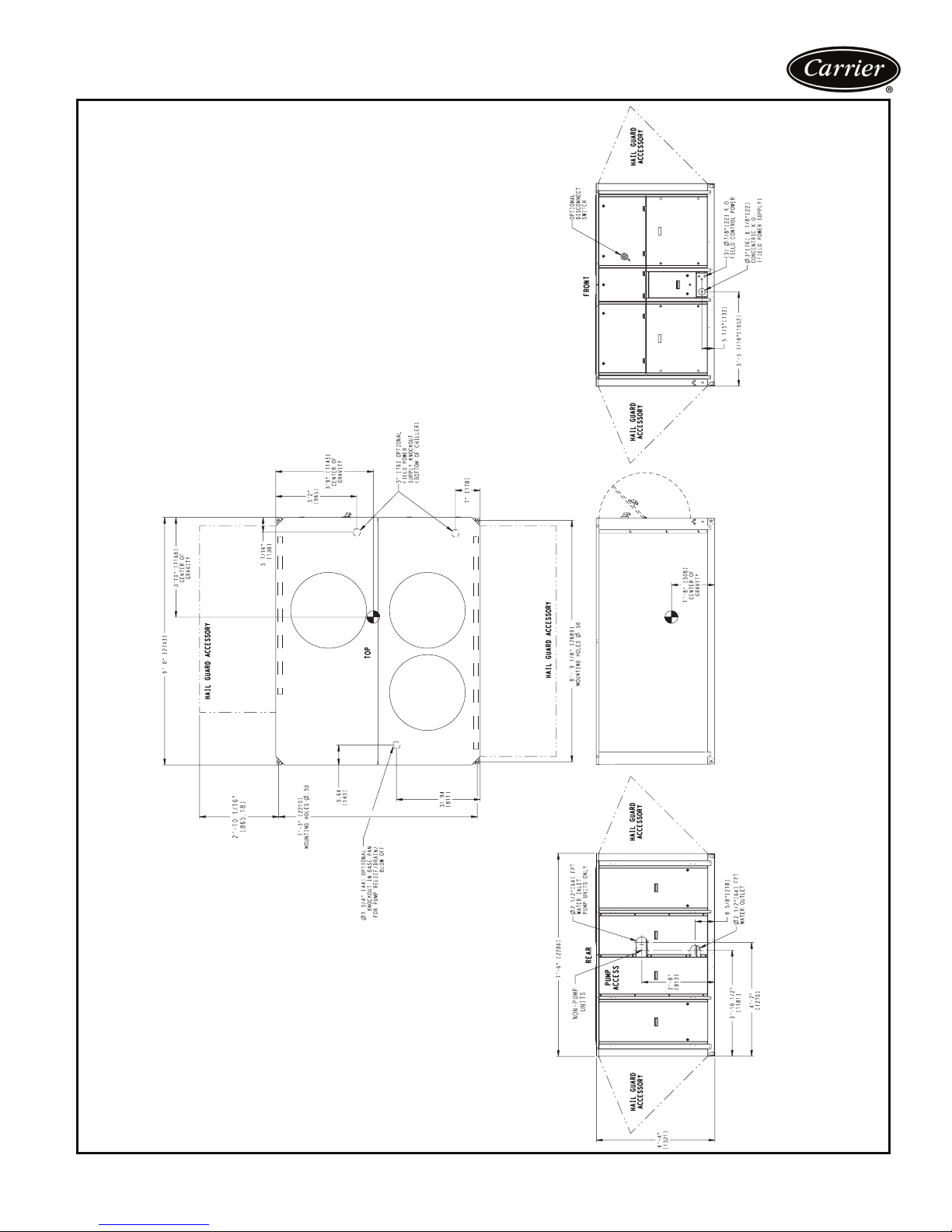
Dimensions — 30RA035,040
installed is 3 ft [914 mm] to outside edge of hail
guard top panel.
6 ft [1981 mm].
Flow switch is factory installed in the leaving fluid
TOP — Do not restrict in any way
COIL SIDE — 3 1/2 ft [1067 mm] from solid surface
OTHER SIDE AND ENDS — 3 ft [914 mm] from
solid surface (for service access)
1. Unit must have clearances for airflow as follows:
NOTES:
2. Coil side clearance with accessory hail guard
piping.
3. Coil side clearance for multiple chiller installation is
4. Strainer is factory installed in entering fluid piping.
5. Dimensions in [ ] are in mm.
13
Page 14
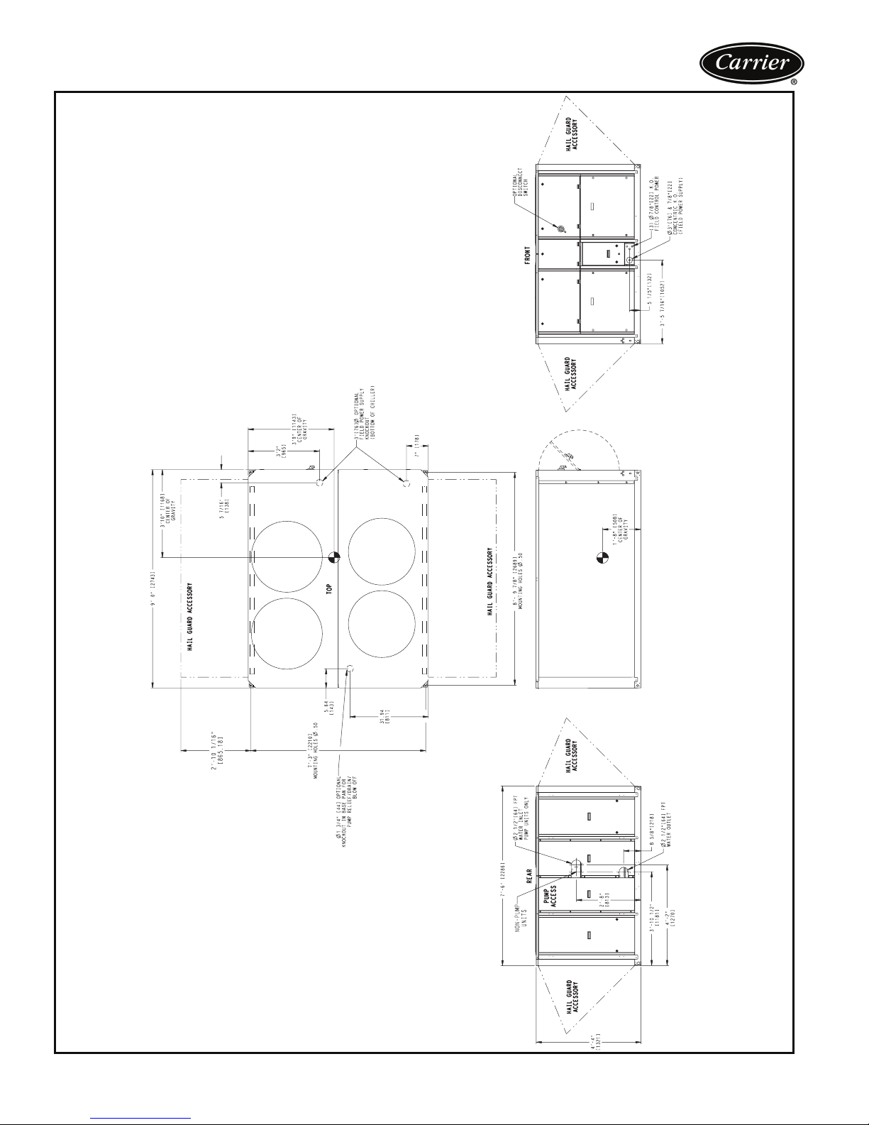
Dimensions — 30RA045,050
installed is 3 ft [914 mm] to outside edge of hail
guard top panel.
6 ft [1981 mm].
Flow switch is factory installed in the leaving fluid
TOP — Do not restrict in any way
COIL SIDE — 3 1/2 ft [1067 mm] from solid surface
OTHER SIDE AND ENDS — 3 ft [914 mm] from
solid surface (for service access)
1. Unit must have clearances for airflow as follows:
NOTES:
2. Coil side clearance with accessory hail guard
piping.
3. Coil side clearance for multiple chiller installation is
4. Strainer is factory installed in entering fluid piping.
5. Dimensions in [ ] are in mm.
14
a30-4601
Page 15
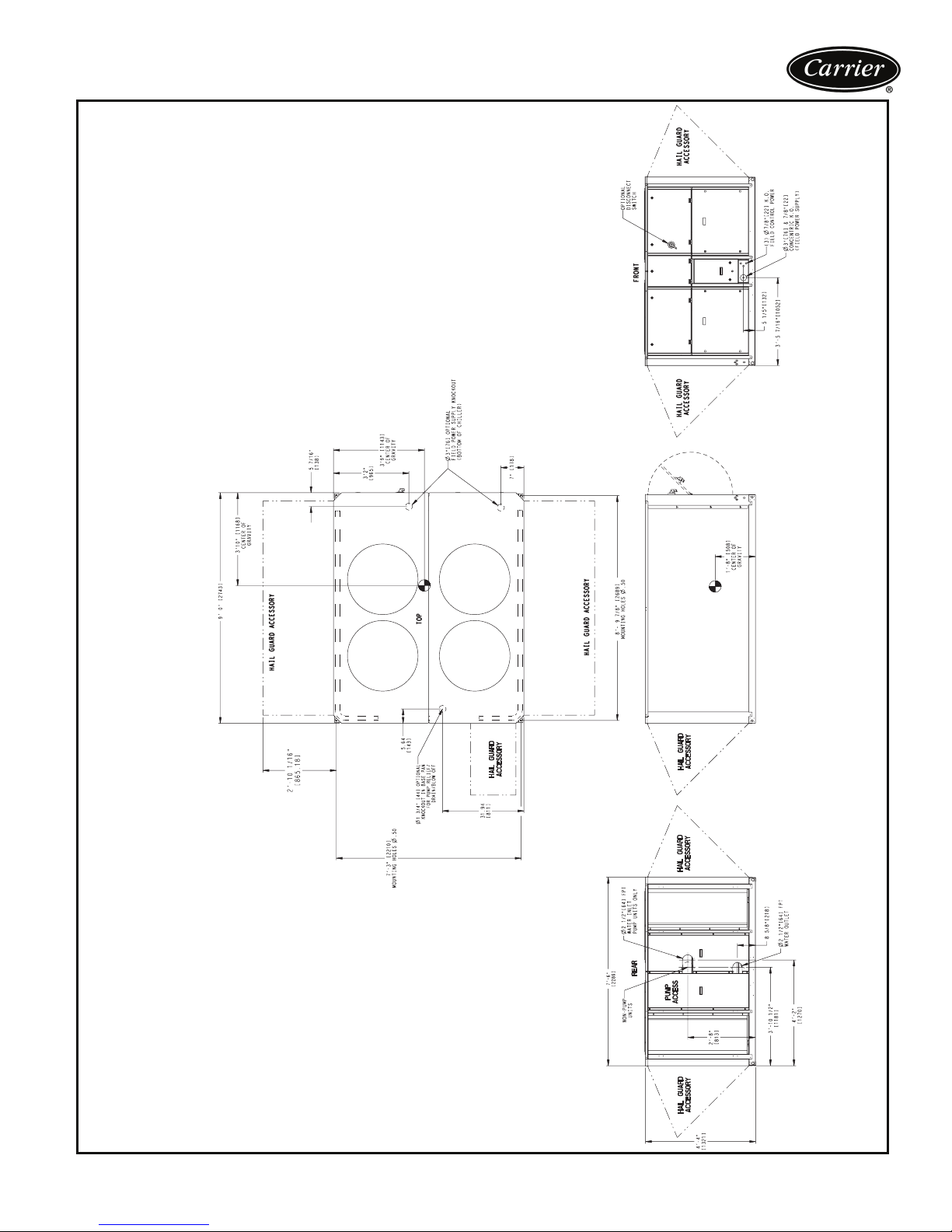
Dimensions — 30RA055
installed is 3 ft [914 mm] to outside edge of hail
guard top panel.
6 ft [1981 mm].
Flow switch is factory installed in the leaving fluid
TOP — Do not restrict in any way
COIL SIDE — 3 1/2 ft [1067 mm] from solid surface
OTHER SIDE AND ENDS — 3 ft [914 mm] from
solid surface (for service access)
1. Unit must have clearances for airflow as follows:
NOTES:
2. Coil side clearance with accessory hail guard
3. Coil side clearance for multiple chiller installation is
piping.
4. Strainer is factory installed in entering fluid piping.
a30-4602
5. Dimensions in [ ] are in mm.
15
Page 16
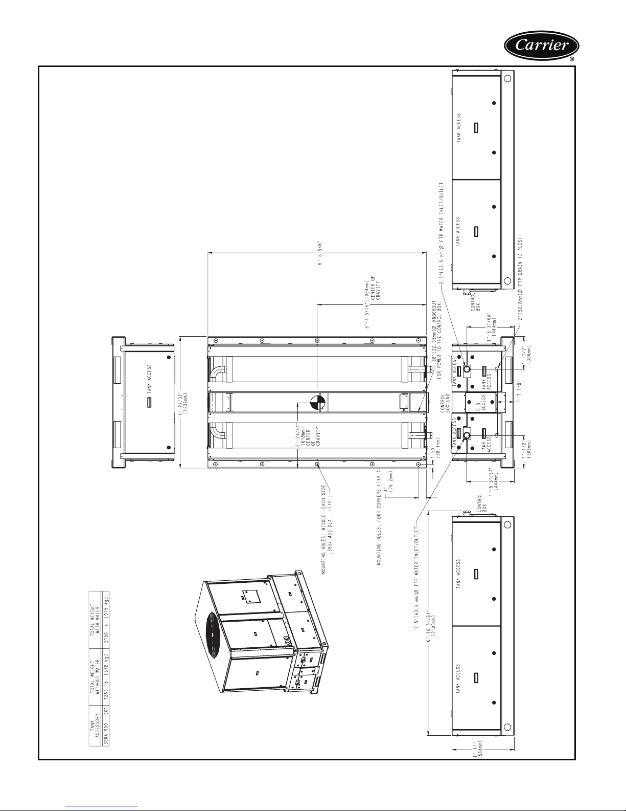
Dimensions — storage tank 30RA010-018
16
a30-4603
Page 17
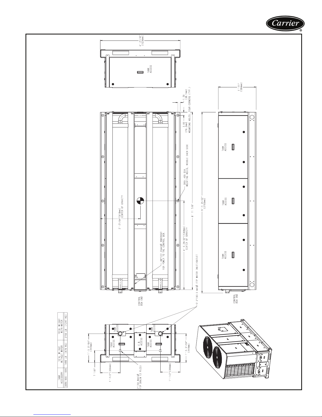
Dimensions — storage tank 30RA022-030
a30-4604
17
Page 18
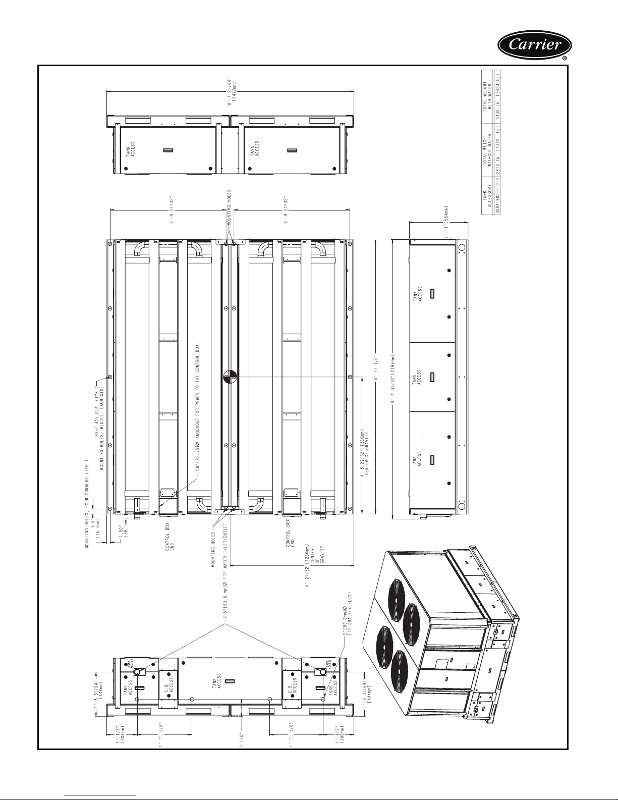
Dimensions — storage tank 30RA035-055
18
a30-4605
Page 19

Selection procedure
Carrier’s electronic catalog chiller selection program provides quick, easy selection of Carrier chillers. The program
considers specific temperature, fluid, and flow requirements and other factors, such as fouling and altitude
correction.
To select a 30RA chiller, use the electronic catalog or
follow one of the procedures below.
ENGLISH EXAMPLE
I Determine 30RA unit size and operating
conditions required to meet given capacity at
given conditions.
Given:
Capacity. . . . . . . . . . . . . . . . . . . . . . . . . 43 Tons
Leaving Chilled Water Temp (LCWT) . . . . . . .44 F
Cooler Water Temp Rise . . . . . . . . . . . . . . . 10° F
Condenser Entering Air Temp . . . . . . . . . . . .95 F
Fouling Factor (Cooler) . . . . . . . . . . . . . .0.00010
NOTE: For other than 10° F temperature rise, data
corrections must be made using the chiller program
in the electronic catalog.
II From Chiller Ratings table on page 26 and
pressure drop curves on page 23, determine
operating data for selected unit.
Unit . . . . . . . . . . . . . . . . 30RA-045 (single pump)
Capacity. . . . . . . . . . . . . . . . . . . . . . . .43.1 Tons
Chiller Power Input . . . . . . . . . . . . . . . . .51.1 kW
Cooler Water Flow . . . . . . . . . . . . . . . 103.3 gpm
Internal Pressure Drop. . . . . . . . . .20.5 ft of water
III Single pump selection. (See AquaSnap
pump selection on page 20.)
Required GPM (from above) . . . . . . . . . 103.3 gpm
Chiller Pressure Drop
(from chart on page 23) . . . . . . . . . . 20.5 ft wg
Additional External System
Pressure Drop (from jobsite) . . . . . . . . . 40 ft wg
Add Chiller Pressure and External
Pressure Drop . . . . . . . . . . . . . . . . . 60.5 ft wg
Using Pump Curve on page 21
Select . . . . . . . . . . Pump E at 103.1, 60.5 ft wg
To find pump horsepower, follow the 4.63-in. im-
peller curve for pump E on page 21.
Hp: . . . . . . . . . . . . . . . . . . . . . . . . . . . . 3.6 bhp
Max hp = 5 hp, therefore necessary hp does not exceed pump rating.
SI EXAMPLE
®
I Determine unit size and operating conditions
required to meet given capacity at given
conditions.
Given:
Capacity. . . . . . . . . . . . . . . . . . . . . . . . . 160 kW
Leaving Chilled Water Temp (LCWT) . . . . . . . 6 C
Cooler Water Temp Rise . . . . . . . . . . . . . . 5.6° C
Condenser Entering Air Temp . . . . . . . . . . . 35 C
Fouling Factor (Cooler) . . . . . . . . . . . . .0.000018
NOTE: For other than 6° C temperature rise, data
corrections must be made using the chiller program
in the electronic catalog.
II From Chiller Ratings table on page 27 and
pressure drop curves on page 23, determine
operating data for selected unit.
Unit . . . . . . . . . . . . . . . . 30RA-050 (single pump)
Capacity. . . . . . . . . . . . . . . . . . . . . . . . 163.4 kW
Chiller Power Input . . . . . . . . . . . . . . . . .59.0 kW
Cooler Water Flow . . . . . . . . . . . . . . . . . .7.0 L/s
Chiller Pressure Drop . . . . . . . . . . . . . . 67.0 kPa
III Pump selection. (See AquaSnap pump selec-
tion on page 20.)
Required Flow
(from above) . . . . . . . . .7.0 x 3.6 = 25.2 m
Chiller Pressure Drop
(from chart on page 23) . . . . . . . . . . . 67.0 kPa
Additional External System
Pressure Drop (from jobsite) . . . . . . . . . 176 kPa
Add Chiller Pressure and External
Pressure Drop . . . . . .243 x .1018 = 24.7 m wg
Using Pump Curve on page 21
Select . . . Pump E at 25.2 m
To find pump horsepower, follow the 4.63-in. im-
peller curve for pump E on page 21.
Hp: . . . . . . . . . . . . . . . . . . . . . . . . . . . 3.86 bhp
Max hp = 5 hp, therefore necessary hp does not exceed pump rating.
3
/hr and 24.7 m wg
3
/hr
19
Page 20

Selection procedure (cont)
AquaSnap® pump selection
Several pump sizes are available for each AquaSnap chiller
size to provide flexibility in matching water system requirements. A dual pump option is also available for primary/
standby operation. The Carrier E-Cat Packaged AC Chiller
Builder can be used for pump selection, or selection can be
done manually.
Proper water system design is critical; cooling loads,
water pressure drops and proper water line sizing must be
accounted for in order to ensure proper system operation.
Incorrect or incomplete analysis/design of the water loop
could lead to low water flow, loss of water temperature
control, and excessive cycling of chiller compressors.
The following are the steps for manual selection of water
pumps for the 30RA chillers.
1. Calculate the water flow rate (gpm) and the total
water pressure drop of the system external to the
30RA chiller.
2. Determine the internal pressure drop of the chiller
hydronic package based on the design flow rate (refer
to internal Pressure Drop tables on page 22). Values
given in these charts are based on units with clean
strainers and circuit setter valve wide open.
NOTE: These pressure drops are for water. If glycol is
used, correct by multiplying by the factors below.
3. If an optional storage tank is used, determine the
internal pressure drop by referencing the internal
Pressure Drop tables on page 24.
NOTE: Note that these pressure drops are for water. If glycol is used, correct by multiplying by the factors below.
% GLYCOL
0 (Pure Water) 11
10 1.062 1.077
20 1.114 1.168
30 1.177 1.271
40 1.248 1.393
50 1.316 1.543
ETHYLENE
GLYCOL
PROPYLENE
GLYCOL
4. Add pressure drops found in Steps 1-3. This is the
total pressure drop and total head required by the
pump.
5. Use the pump envelope charts (page 25) to determine proper pump sizing. Plot water flow rate
(Step 1) and total head (Step 4), point on the chart.
The region containing the point corresponds to the
correct pump.
NOTE: Although pump bhp increases with glycol concentration, pumps and pump overloads are selected such that
glycol concentrations up to 50% will not trip pump overloads if run within the recommended gpm ranges.
Example: Required water flow rate for a 30RA018
chiller is 45 gpm. The pressure drop in feet for the water
system external to the chiller is 50 feet. The system does
not have an accessory storage tank. The single pump is
needed. Select the pump.
Since the flow rate and external head losses (Step 1) are
known, the internal losses in the hydronic package must be
found (Step 2). Using the pressure drop graphs (page 22)
for the 30RA018 units, the internal loss at 45 gpm is
15 feet. Since no accessory storage tank is being used
(Step 3), the pressure drop is 0 feet.
Add all losses together (Step 4). The total pressure rise
needed by the pump is 50 + 15 + 0 = 65 feet. The pump
selection becomes pump C.
20
Page 21
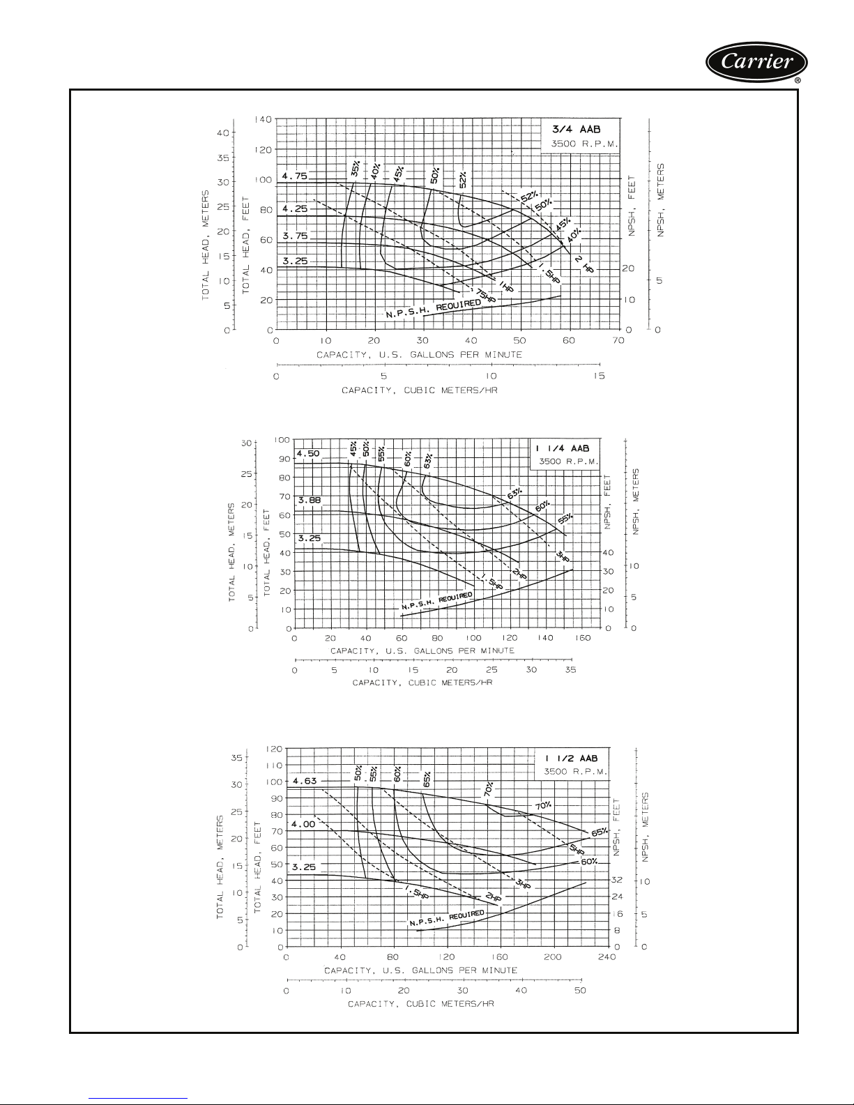
PUMP CURVE FOR HYDRONIC PACKAGE OPTIONS A, C, F, AND H (1.5-2.0 Hp)
PUMP CURVE FOR HYDRONIC PACKAGE OPTIONS B, D, G, AND J (2-3 Hp)
PUMP CURVE FOR HYDRONIC PACKAGE OPTIONS E AND K (5.0 Hp)
NPSH — Net Postive Suction Head
21
Page 22
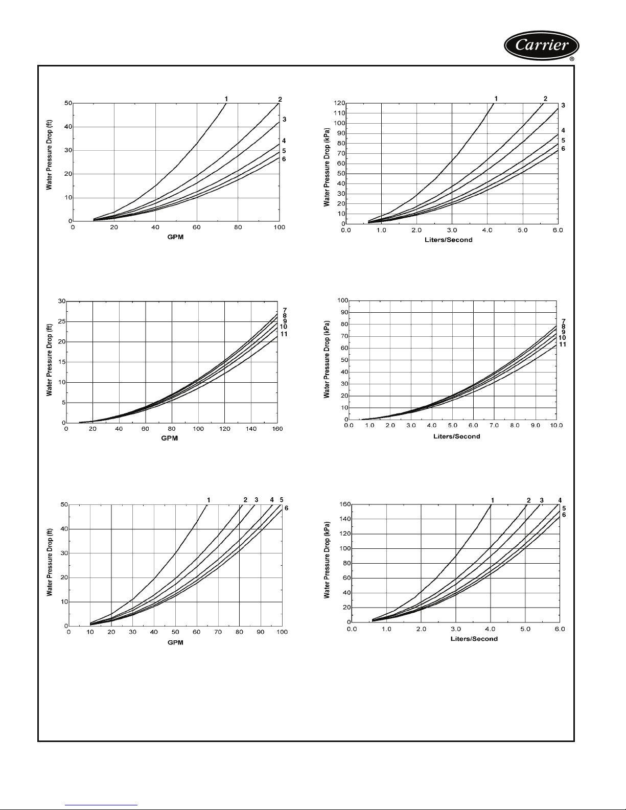
Selection procedure (cont)
PRESSURE DROP, WITHOUT PUMP UNITS,
30RA010-030 (English)
PRESSURE DROP, WITHOUT PUMP UNITS,
30RA035-055 (English)
PRESSURE DROP, WITHOUT PUMP UNITS,
30RA010-030 (SI)
PRESSURE DROP, WITHOUT PUMP UNITS,
30RA035-055 (SI)
PRESSURE DROP, SINGLE PUMP UNITS,
Use the following formula to convert feet of water to psig:
ft of water (.4335) = psig
30RA010-030 (English)
1 — 30RA010 3 — 30RA018 5 — 30RA025 7 — 30RA035 9 — 30RA045 11 — 30RA055
2 — 30RA015 4 — 30RA022 6 — 30RA030 8 — 30RA040 10 — 30RA050
PRESSURE DROP, SINGLE PUMP UNITS,
Use the following formula to convert psig to feet of water:
psig (2.306) = ft of water
LEGEND
30RA010-030 (SI)
22
Page 23
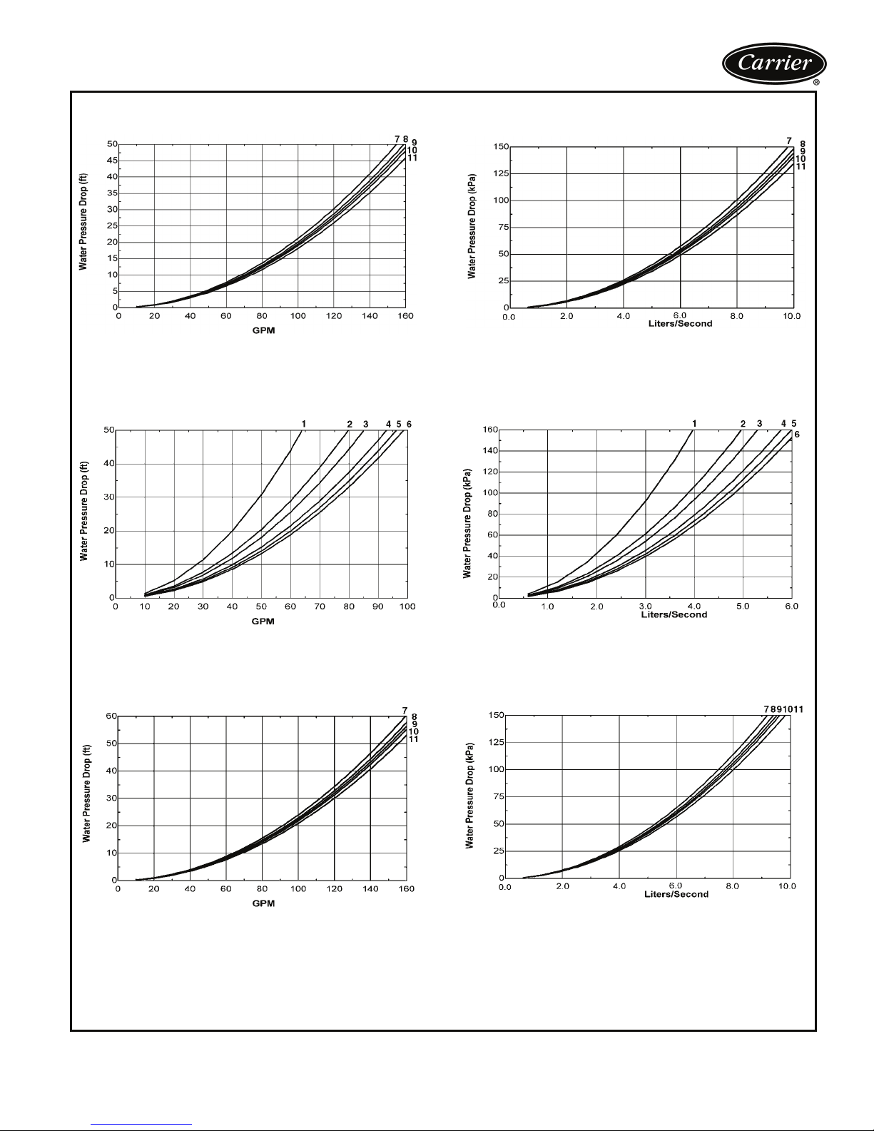
PRESSURE DROP, SINGLE PUMP UNITS,
30RA035-055 (English)
PRESSURE DROP, SINGLE PUMP UNITS,
30RA035-055 (SI)
PRESSURE DROP, DUAL PUMP UNITS,
SIZES 30RA010-030 (English)
PRESSURE DROP, DUAL PUMP UNITS,
SIZES 30RA035-055 (English)
PRESSURE DROP, DUAL PUMP UNITS,
SIZES 30RA010-030 (SI)
PRESSURE DROP, DUAL PUMP UNITS,
SIZES 30RA035-055 (SI)
Use the following formula to convert feet of water to psig:
ft of water (.4335) = psig
1 — 30RA010 3 — 30RA018 5 — 30RA025 7 — 30RA035 9 — 30RA045 11 — 30RA055
2 — 30RA015 4 — 30RA022 6 — 30RA030 8 — 30RA040 10 — 30RA050
Use the following formula to convert psig to feet of water:
psig (2.306) = ft of water
LEGEND
23
Page 24
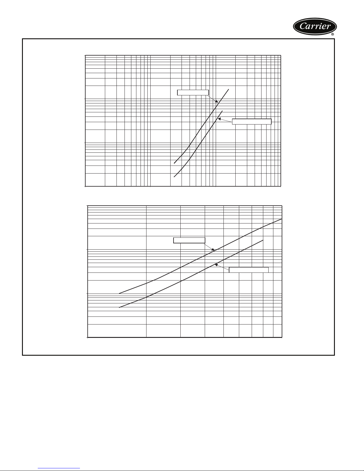
Selection procedure (cont)
STORAGE TANK PRESSURE DROP CURVES
100.0
10.0
PRESSURE DROP (ft wg)
1.0
30RA-900---010
30RA-900---001,009
0.1
1
100.0
10.0
PRESSURE DROP (kPa)
1.0
0.1
1.0 10.0
10
ACCESSORY TANK FLOW RATE (gpm)
30RA-900---010
ACCESSORY TANK FLOW RATE (L/s)
100 1000
30RA-900---001,009
24
Page 25
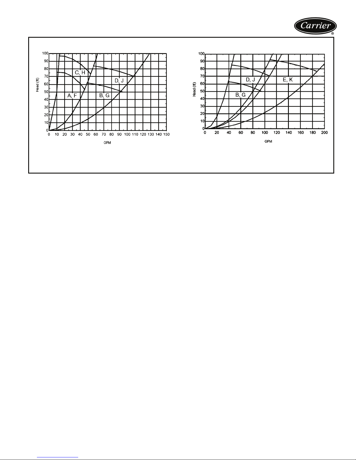
30RA010-030 PUMP ENVELOPES
NOTES:
1. Refer to Position 9 in the unit’s model number for pump identification.
2. To convert gpm to L/s, multiply by 0.063. To convert head pressure to
kPa, multiply by 2.986.
30RA035-055 PUMP ENVELOPES
Expansion tank selection and filling
Expansion tanks are essential to the operation of any
closed, pressurized, hydronic system. They perform four
important functions: 1) provide for expansion of the liquid
as the temperature in the system rises, 2) act as a pressure
reference for the system, 3) supply sufficient pressure to
prevent cavitation, 4) provide a location to charge the
system.
The AquaSnap
bladder-style expansion tank, pre-charged to 40 psig
(277 kPa) pressure and pre-selected for loop volumes up to
6 gallons per ton. If loop volumes in excess of those indicated in the loop volume chart on page 43 are required,
then a field-installed expansion tank must be provided, and
the expansion tank in AquaSnap hydronic package must
be removed.
®
optional hydronic package includes a
If the top of the piping system (the highest point in the
hydronic piping) is more than 80 ft (12.2 m) above the
chiller, then the expansion tank will require additional air
pressure charge. The expansion tank must be pressurized
to provide at least 4 psig (28 kPa) of positive pressure at
the highest point in the hydronic piping system. This will
also ensure no air is drawn into the piping. The amount of
charge pressure in pounds per square inch (psi) that is
required in the expansion tank is equal to 4 psig (28 kPa)
plus the height (in feet) from the chiller to the highest point
in the hydronic system divided by 2.31.
Example: The 30RA AquaSnap elevation is 10 ft (3.1 m).
The hydronic system is piped to an air handler on the roof
with an elevation of 100 ft (30.5 m). The total pressure
required in the expansion tank is:
4 psig + (100 ft – 10 ft)/2.31 = 42.96 psig
28 kPa + (30.5 m – 3.1 m)/0.102 = 296 kPa
The expansion tank will require an additional 3 psig
(19 kPa) of pressure.
25
Page 26

Performance data
PACKAGED AIR-COOLED CHILLER RATINGS TABLE — ENGLISH
LCWT
(F)
40.00
42.00
44.00
45.00
46.00
48.00
50.00
55.00
60.00
LCWT — Leaving Chilled Water Temperature
UNIT
SIZE
30RA-010 9.4 10.5 22.4 8.9 11.5 21.4 8.5 12.7 20.3 8.0 14.0 19.1 7.7 14.7 18.4
30RA-015 13.4 15.1 32.2 12.8 16.5 30.6 12.1 18.1 29.0 11.4 19.8 27.2 11.0 20.7 26.3
30RA-018 15.6 17.8 37.4 14.8 19.6 35.5 14.0 21.6 33.5 13.1 23.8 31.4 12.6 25.1 30.3
30RA-022 20.7 22.5 49.5 19.7 24.7 47.2 18.7 27.3 44.7 17.5 30.1 41.8 16.8 31.6 40.3
30RA-025 23.4 26.6 56.1 22.3 29.1 53.3 21.0 31.8 50.2 19.5 34.8 46.7 18.7 36.4 44.9
30RA-030 26.7 29.8 63.9 25.4 32.8 60.7 24.0 36.1 57.4 22.5 39.8 53.9 11.8 19.2 28.3
30RA-035 34.1 37.2 81.6 32.5 40.8 77.8 30.7 44.8 73.6 28.8 49.3 69.1 27.8 51.7 66.7
30RA-040 37.1 41.8 88.7 35.2 45.6 84.4 33.3 49.9 79.6 31.1 54.7 74.5 29.9 57.2 71.7
30RA-045 42.3 45.5 101.2 40.3 50.1 96.4 38.1 55.2 91.2 35.6 60.9 85.3 34.3 63.9 82.2
30RA-050 46.6 53.1 111.7 44.3 58.1 106.1 41.7 63.5 99.9 38.9 69.5 93.1 37.3 72.7 89.4
30RA-055 53.2 59.7 127.4 50.6 65.5 121.2 47.8 72.1 114.5 44.9 79.5 107.6 23.6 38.3 56.5
30RA-010 9.7 10.6 23.2 9.2 11.6 22.2 8.8 12.7 21.0 8.2 14.1 19.8 8.0 14.8 19.1
30RA-015 13.9 15.3 33.4 13.3 16.7 31.8 12.5 18.2 30.1 11.8 20.0 28.3 11.4 20.9 27.3
30RA-018 16.2 18.0 38.8 15.4 19.8 36.9 14.5 21.8 34.8 13.6 24.0 32.6 13.1 25.3 31.4
30RA-022 21.4 22.7 51.3 20.4 25.0 48.9 19.3 27.5 46.3 18.1 30.3 43.4 17.4 31.9 41.8
30RA-025 24.2 26.9 58.1 23.0 29.4 55.2 21.7 32.1 52.0 20.2 35.2 48.4 19.4 36.8 46.5
30RA-030 27.6 30.2 66.2 26.3 33.1 63.0 24.9 36.5 59.6 23.3 40.2 56.0 12.3 19.3 29.4
30RA-035 35.3 37.5 84.5 33.6 41.1 80.6 31.8 45.2 76.3 29.9 49.7 71.6 28.8 52.1 69.1
30RA-040 38.3 42.2 91.9 36.5 46.1 87.4 34.4 50.4 82.5 32.2 55.2 77.2 31.0 57.8 74.4
30RA-045 43.7 46.0 104.7 41.7 50.6 99.8 39.4 55.7 94.4 36.9 61.4 88.4 35.6 64.5 85.3
30RA-050 48.2 53.7 115.6 45.8 58.7 109.9 43.2 64.2 103.5 40.2 70.3 96.4 38.6 73.5 92.6
30RA-055 55.1 60.3 132.1 52.4 66.3 125.7 49.6 72.9 118.9 46.6 80.3 111.7 24.5 38.5 58.8
30RA-010 10.0 10.6 24.0 9.6 11.7 22.9 9.1 12.8 21.8 8.5 14.1 20.5 8.3 14.8 19.8
30RA-015 14.4 15.4 34.6 13.7 16.8 32.9 13.0 18.4 31.2 12.2 20.1 29.3 11.8 21.1 28.4
30RA-018 16.8 18.2 40.3 15.9 20.0 38.2 15.0 22.0 36.1 14.1 24.2 33.8 13.6 25.5 32.6
30RA-022 22.1 22.9 53.0 21.1 25.2 50.6 20.0 27.8 47.9 18.7 30.6 44.9 18.1 32.1 43.3
30RA-025 25.0 27.2 60.1 23.8 29.7 57.1 22.4 32.5 53.8 20.9 35.5 50.1 11.6 16.9 27.8
30RA-030 28.6 30.5 68.6 27.2 33.5 65.3 25.8 36.8 61.8 24.2 40.6 58.1 12.8 19.4 30.6
30RA-035 36.5 37.9 87.4 34.8 41.5 83.4 32.9 45.6 78.9 30.9 50.1 74.2 29.9 52.5 71.6
30RA-040 39.7 42.7 95.1 37.7 46.6 90.5 35.6 50.9 85.4 33.3 55.7 80.0 23.7 38.2 56.9
30RA-045 45.2 46.5 108.3 43.1 51.1 103.3 40.7 56.3 97.7 38.2 62.0 91.6 36.8 65.0 88.3
30RA-050 49.9 54.3 119.6 47.4 59.4 113.7 44.7 64.9 107.1 41.6 71.0 99.8 23.1 33.9 55.4
30RA-055 57.1 61.0 136.9 54.3 67.0 130.3 51.4 73.7 123.3 48.3 81.2 115.9 25.5 38.8 61.1
30RA-010 10.2 10.7 24.4 9.7 11.7 23.3 9.2 12.9 22.1 8.7 14.2 20.8 8.4 14.9 20.2
30RA-015 14.7 15.5 35.2 14.0 16.9 33.5 13.2 18.5 31.7 12.5 20.2 29.9 12.0 21.2 28.9
30RA-018 17.1 18.2 41.0 16.2 20.0 38.9 15.3 22.1 36.7 14.3 24.3 34.4 13.9 25.6 33.2
30RA-022 22.5 23.0 53.9 21.4 25.3 51.4 20.3 27.9 48.7 19.0 30.7 45.7 18.4 32.3 44.1
30RA-025 25.5 27.4 61.1 24.2 29.9 58.1 22.8 32.7 54.7 21.3 35.7 51.0 11.8 17.0 28.4
30RA-030 29.1 30.7 69.8 27.7 33.7 66.5 26.2 37.0 62.9 24.6 40.8 59.1 13.0 19.4 31.2
30RA-035 37.1 38.1 88.9 35.4 41.7 84.8 33.5 45.8 80.3 31.5 50.3 75.5 30.4 52.7 72.9
30RA-040 40.3 42.9 96.7 38.4 46.8 92.1 36.2 51.2 86.9 33.9 56.0 81.4 24.2 38.3 58.0
30RA-045 45.9 46.7 110.1 43.8 51.4 105.0 41.4 56.5 99.4 38.9 62.3 93.2 37.5 65.3 89.9
30RA-050 50.7 54.7 121.6 48.2 59.7 115.6 45.4 65.3 108.9 42.3 71.3 101.5 23.5 34.0 56.5
30RA-055 58.1 61.4 139.4 55.3 67.4 132.6 52.3 74.1 125.5 49.2 81.6 118.0 26.0 38.9 62.3
30RA-010 10.3 10.7 24.8 9.9 11.7 23.7 9.4 12.9 22.5 8.8 14.2 21.2 8.6 14.9 20.5
30RA-015 14.9 15.6 35.8 14.2 17.0 34.1 13.5 18.5 32.3 12.7 20.3 30.4 12.3 21.3 29.4
30RA-018 17.4 18.3 41.7 16.5 20.1 39.6 15.6 22.2 37.4 14.6 24.4 35.0 14.1 25.7 33.8
30RA-022 22.9 23.2 54.8 21.8 25.5 52.3 20.6 28.0 49.5 19.4 30.9 46.5 18.7 32.4 44.8
30RA-025 25.9 27.5 62.1 24.6 30.1 59.0 23.2 32.9 55.6 21.6 35.9 51.9 12.0 17.0 28.9
30RA-030 29.6 30.8 71.1 28.2 33.9 67.6 26.7 37.2 64.0 25.1 41.0 60.2 13.2 19.5 31.8
30RA-035 37.7 38.3 90.4 35.9 41.9 86.2 34.0 46.0 81.7 32.0 50.5 76.8 30.9 53.0 74.2
30RA-040 41.0 43.1 98.4 39.0 47.1 93.6 36.9 51.5 88.4 34.5 56.3 82.8 24.6 38.4 59.0
30RA-045 46.7 46.9 112.0 44.5 51.6 106.8 42.1 56.8 101.1 39.5 62.5 94.8 38.1 65.6 91.4
30RA-050 51.5 55.0 123.7 49.0 60.1 117.6 46.2 65.6 110.8 43.0 71.7 103.3 24.0 34.1 57.5
30RA-055 59.1 61.7 141.8 56.3 67.8 135.0 53.2 74.5 127.8 50.1 82.0 120.1 26.4 39.0 63.4
30RA-010 10.7 10.8 25.6 10.2 11.8 24.5 9.7 13.0 23.3 9.1 14.3 21.9 8.8 15.0 21.2
30RA-015 15.4 15.7 37.1 14.7 17.1 35.3 13.9 18.7 33.5 13.1 20.5 31.5 12.7 21.4 30.5
30RA-018 18.0 18.5 43.2 17.1 20.3 41.0 16.1 22.4 38.7 15.1 24.6 36.3 14.6 25.9 35.1
30RA-022 23.6 23.4 56.6 22.5 25.7 54.1 21.3 28.3 51.2 20.0 31.2 48.1 19.3 32.7 46.4
30RA-025 26.7 27.9 64.2 25.4 30.4 61.0 24.0 33.2 57.5 22.3 36.3 53.6 12.5 17.2 30.0
30RA-030 30.7 31.2 73.6 29.2 34.3 70.0 27.6 37.7 66.3 26.0 41.4 62.4 13.7 19.6 33.0
30RA-035 38.9 38.6 93.5 37.1 42.3 89.2 35.2 46.4 84.5 33.1 51.0 79.4 32.0 53.4 76.8
30RA-040 42.4 43.6 101.7 40.3 47.6 96.8 38.1 52.0 91.5 35.7 56.8 85.6 25.5 38.7 61.2
30RA-045 48.2 47.4 115.7 46.0 52.1 110.3 43.5 57.3 104.5 40.8 63.1 98.0 39.4 66.2 94.6
30RA-050 53.3 55.6 127.8 50.6 60.7 121.5 47.7 66.4 114.5 44.5 72.5 106.8 24.8 34.3 59.6
30RA-055 61.2 62.4 146.8 58.2 68.5 139.8 55.1 75.3 132.3 51.9 82.9 124.5 27.4 39.3 65.9
30RA-010 11.0 10.8 26.4 10.5 11.9 25.3 10.0 13.0 24.0 9.4 14.3 22.7 9.1 15.1 22.0
30RA-015 16.0 15.8 38.4 15.2 17.3 36.6 14.4 18.9 34.7 13.6 20.7 32.6 13.2 21.6 31.6
30RA-018 18.6 18.7 44.7 17.7 20.5 42.5 16.7 22.5 40.1 15.7 24.8 37.6 15.1 26.1 36.3
30RA-022 24.4 23.6 58.5 23.2 26.0 55.8 22.0 28.6 52.9 20.7 31.4 49.7 20.0 33.0 48.0
30RA-025 27.6 28.2 66.3 26.2 30.8 63.0 24.7 33.6 59.4 23.1 36.7 55.4 12.9 17.3 31.0
30RA-030 31.7 31.6 76.1 30.2 34.6 72.5 28.6 38.1 68.7 26.9 41.9 64.6 14.2 19.7 34.2
30RA-035 40.2 39.0 96.5 38.4 42.7 92.1 36.4 46.8 87.3 34.2 51.4 82.1 33.1 53.9 79.4
30RA-040 43.8 44.1 105.1 41.7 48.1 100.0 39.4 52.5 94.5 36.9 57.4 88.5 26.4 39.0 63.3
30RA-045 49.7 47.9 119.4 47.5 52.7 114.0 44.9 57.9 107.9 42.2 63.7 101.3 40.7 66.8 97.8
30RA-050 55.0 56.3 132.0 52.3 61.5 125.5 49.3 67.1 118.3 46.0 73.2 110.4 25.7 34.5 61.8
30RA-055 63.3 63.2 151.9 60.2 69.3 144.7 57.1 76.2 137.0 53.7 83.8 128.9 28.4 39.5 68.3
30RA-010 11.9 11.0 28.5 11.4 12.0 27.3 10.8 13.2 26.0 10.2 14.5 24.6 9.9 15.2 23.8
30RA-015 17.4 16.2 41.7 16.5 17.7 39.8 15.7 19.3 37.7 14.8 21.1 35.5 14.3 22.1 34.4
30RA-018 20.2 19.2 48.6 19.2 21.0 46.2 18.2 23.1 43.6 17.0 25.4 41.0 16.5 26.6 39.6
30RA-022 26.3 24.3 63.2 25.1 26.6 60.4 23.8 29.3 57.2 22.4 32.1 53.8 21.6 33.7 52.0
30RA-025 29.8 29.1 71.7 28.4 31.7 68.2 26.7 34.5 64.3 25.0 37.7 60.0 13.9 17.5 33.3
30RA-030 34.4 32.5 82.7 32.8 35.7 78.8 31.1 39.2 74.7 29.3 43.0 70.3 15.2 20.0 36.6
30RA-035 43.5 40.0 104.5 41.5 43.8 99.7 39.4 47.9 94.6 37.1 52.6 89.1 35.8 55.0 86.1
30RA-040 47.3 45.3 113.8 45.1 49.4 108.3 42.6 53.9 102.4 40.0 58.9 96.0 28.5 39.7 68.4
30RA-045 53.7 49.2 129.1 51.3 54.0 123.2 48.6 59.3 116.8 45.7 65.1 109.8 44.1 68.3 106.0
30RA-050 59.4 58.0 142.8 56.5 63.3 135.8 53.3 69.0 128.0 49.7 75.2 119.5 27.6 34.9 66.3
30RA-055 68.7 65.1 165.1 65.5 71.4 157.3 62.0 78.4 149.1 58.4 86.1 140.4 30.4 40.0 73.2
30RA-010 12.3 11.1 29.6 11.7 12.1 28.2 11.1 13.3 26.8 10.5 14.6 25.3 10.2 15.3 24.4
30RA-015 18.2 16.5 43.7 17.2 17.9 41.5 16.3 19.5 39.2 15.3 21.3 36.7 14.8 22.3 35.5
30RA-018 21.2 19.5 51.1 20.1 21.3 48.3 18.9 23.3 45.4 17.6 25.6 42.3 9.0 12.3 21.6
30RA-022 27.5 24.6 66.2 26.2 27.0 62.9 24.7 29.6 59.4 23.1 32.4 55.5 22.2 34.0 53.5
30RA-025 31.4 29.7 75.5 29.7 32.2 71.3 27.8 35.1 66.9 25.8 38.1 62.0 13.9 17.5 33.3
30RA-030 36.5 33.3 87.9 34.6 36.4 83.2 32.6 39.8 78.4 30.5 43.6 73.3 15.2 20.0 36.6
30RA-035 45.2 40.5 108.7 43.0 44.2 103.3 40.5 48.4 97.5 37.9 52.9 91.3 36.6 55.4 88.0
30RA-040 49.5 46.2 119.1 46.9 50.2 112.7 44.0 54.6 105.9 41.0 59.4 98.7 28.6 39.8 68.8
30RA-045 56.3 50.1 135.5 53.5 54.8 128.8 50.5 60.0 121.4 47.2 65.8 113.5 45.4 68.9 109.3
30RA-050 62.5 59.3 150.3 59.1 64.4 142.1 55.4 70.0 133.2 51.4 76.1 123.5 27.6 34.9 66.3
30RA-055 73.0 66.6 175.6 69.1 72.8 166.3 65.1 79.7 156.6 60.9 87.3 146.5 30.4 40.0 73.2
LEGEND
Cap.
(Tons)
85 95 105 115 120
Cooler
Input
Flow Rate
kW
(Gpm)
Cap.
(Tons)
Input
kW
CONDENSER ENTERING AIR TEMPERATURE (F)
Cooler
Flow Rate
(Gpm)
Cap.
(Tons)
Input
kW
Cooler
Flow Rate
(Gpm)
Cap.
(Tons)
Input
kW
Cooler
Flow Rate
(Gpm)
Cap.
(Tons)
Input
kW
Cooler
Flow Rate
(Gpm)
26
Page 27
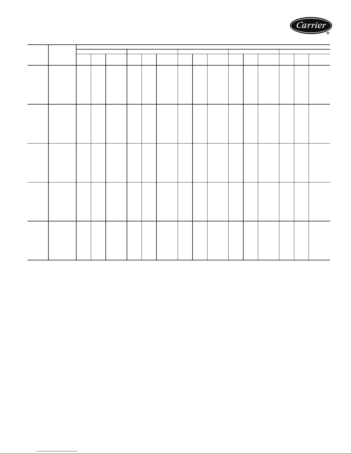
LCWT
(C)
5.00
6.00
7.00
8.00
10.00
LCWT — Leaving Chilled Water Temperature
UNIT
SIZE
30RA-010 33.4 10.6 1.4 32.0 11.6 1.4 30.5 12.6 1.3 28.9 13.7 1.2 27.2 15.0 1.2
30RA-015 47.9 15.3 2.1 45.8 16.6 2.0 43.6 18.0 1.9 41.3 19.5 1.8 38.8 21.2 1.7
30RA-018 55.7 18.1 2.4 53.1 19.7 2.3 50.4 21.5 2.2 47.6 23.5 2.0 44.6 25.7 1.9
30RA-022 73.7 22.8 3.2 70.5 24.9 3.0 67.1 27.1 2.9 63.4 29.6 2.7 59.3 32.4 2.6
30RA-025 83.4 27.0 3.6 79.6 29.2 3.4 75.5 31.7 3.2 70.9 34.4 3.0 38.1 17.1 1.6
30RA-030 95.0 30.3 4.1 90.8 32.9 3.9 86.3 35.9 3.7 81.7 39.2 3.5 41.8 19.6 1.8
30RA-035 121.4 37.7 5.2 116.2 41.0 5.0 110.6 44.6 4.8 104.6 48.5 4.5 98.2 52.9 4.2
30RA-040 132.0 42.4 5.7 126.1 45.9 5.4 119.8 49.7 5.1 112.9 54.0 4.9 77.9 38.4 3.4
30RA-045 150.5 46.2 6.5 144.0 50.3 6.2 1 37.0 54.9 5.9 129.3 60.0 5.6 121.0 65.5 5.2
30RA-050 166.0 53.9 7.1 158.5 58.4 6.8 150.3 63.3 6.5 141.2 68.6 6.1 75.8 34.1 3.3
30RA-055 189.6 60.6 8.1 181.2 65.9 7.8 172.3 71.8 7.4 163.0 78.4 7.0 83.5 39.2 3.6
30RA-010 34.4 10.7 1.5 33.0 11.6 1.4 31.4 12.7 1.4 29.8 13.8 1.3 28.0 15.1 1.2
30RA-015 49.4 15.5 2.1 47.3 16.7 2.0 45.0 18.1 1.9 42.6 19.7 1.8 40.2 21.4 1.7
30RA-018 57.5 18.2 2.5 54.9 19.8 2.4 52.1 21.6 2.2 49.2 23.6 2.1 46.1 25.8 2.0
30RA-022 75.9 23.0 3.3 72.7 25.1 3.1 69.2 27.4 3.0 65.4 29.9 2.8 61.3 32.6 2.6
30RA-025 85.9 27.2 3.7 82.1 29.5 3.5 77.8 32.0 3.3 73.1 34.7 3.1 39.4 17.2 1.7
30RA-030 98.1 30.6 4.2 93.7 33.3 4.0 89.2 36.3 3.8 84.4 39.6 3.6 43.3 19.7 1.9
30RA-035 125.1 38.0 5.4 119.8 41.3 5.2 1 14.1 44.9 4.9 108.0 48.9 4.6 101.4 53.3 4.4
30RA-040 136.1 42.8 5.9 130.0 46.3 5.6 123.5 50.2 5.3 116.5 54.4 5.0 80.6 38.7 3.5
30RA-045 155.0 46.6 6.7 148.5 50.8 6.4 1 41.3 55.4 6.1 133.4 60.5 5.7 124.9 66.0 5.4
30RA-050 171.1 54.4 7.4 163.4 59.0 7.0 154.9 63.9 6.7 145.6 69.3 6.3 78.4 34.3 3.4
30RA-055 195.7 61.2 8.4 187.1 66.6 8.0 178.0 72.5 7.7 168.4 79.1 7.2 86.4 39.4 3.7
30RA-010 35.4 10.7 1.5 34.0 11.7 1.5 32.4 12.7 1.4 30.7 13.9 1.3 28.9 15.2 1.2
30RA-015 51.0 15.6 2.2 48.8 16.9 2.1 46.5 18.3 2.0 44.0 19.8 1.9 41.5 21.5 1.8
30RA-018 59.4 18.4 2.6 56.6 20.0 2.4 53.8 21.8 2.3 50.8 23.8 2.2 26.2 12.3 1.1
30RA-022 78.2 23.2 3.4 74.9 25.3 3.2 71.4 27.6 3.1 67.4 30.1 2.9 63.2 32.9 2.7
30RA-025 88.6 27.5 3.8 84.6 29.8 3.6 80.2 32.3 3.5 75.4 35.0 3.2 40.7 17.3 1.8
30RA-030 101.2 30.9 4.4 96.8 33.6 4.2 92.1 36.6 4.0 87.2 39.9 3.8 44.7 19.8 1.9
30RA-035 128.9 38.3 5.5 123.5 41.6 5.3 1 17.6 45.3 5.1 111.3 49.3 4.8 104.6 53.7 4.5
30RA-040 140.2 43.2 6.0 134.1 46.7 5.8 127.4 50.6 5.5 120.2 54.9 5.2 83.2 38.9 3.6
30RA-045 159.7 47.0 6.9 153.0 51.2 6.6 1 45.6 55.9 6.3 137.6 61.0 5.9 128.9 66.5 5.5
30RA-050 176.3 55.0 7.6 168.4 59.6 7.2 159.7 64.5 6.9 150.1 69.9 6.5 81.0 34.5 3.5
30RA-055 202.0 61.8 8.7 193.1 67.2 8.3 183.8 73.2 7.9 174.0 79.9 7.5 89.4 39.6 3.8
30RA-010 36.4 10.8 1.6 35.0 11.7 1.5 33.4 12.8 1.4 31.7 13.9 1.4 29.9 15.2 1.3
30RA-015 52.6 15.7 2.3 50.4 17.0 2.2 48.0 18.4 2.1 45.5 20.0 2.0 42.9 21.7 1.8
30RA-018 61.3 18.5 2.6 58.5 20.2 2.5 55.5 22.0 2.4 52.4 24.0 2.3 27.1 12.3 1.2
30RA-022 80.5 23.4 3.5 77.2 25.5 3.3 73.5 27.8 3.2 69.5 30.3 3.0 65.2 33.1 2.8
30RA-025 91.2 27.8 3.9 87.1 30.1 3.7 82.6 32.6 3.6 77.7 35.4 3.3 42.1 17.4 1.8
30RA-030 104.4 31.2 4.5 99.8 33.9 4.3 95.0 37.0 4.1 90.0 40.3 3.9 46.3 19.9 2.0
30RA-035 132.8 38.7 5.7 127.2 42.0 5.5 1 21.2 45.6 5.2 114.8 49.7 4.9 107.9 54.1 4.6
30RA-040 144.5 43.6 6.2 138.2 47.2 5.9 131.3 51.1 5.7 123.9 55.4 5.3 85.9 39.2 3.7
30RA-045 164.5 47.5 7.1 157.6 51.7 6.8 1 50.0 56.4 6.5 141.8 61.4 6.1 132.9 67.0 5.7
30RA-050 181.6 55.6 7.8 173.5 60.2 7.5 164.5 65.2 7.1 154.7 70.6 6.7 83.7 34.7 3.6
30RA-055 208.4 62.4 9.0 199.3 67.9 8.6 189.7 74.0 8.2 179.6 80.6 7.7 92.4 39.8 4.0
30RA-010 38.5 10.9 1.7 37.0 11.9 1.6 35.4 12.9 1.5 33.6 14.1 1.4 31.7 15.4 1.4
30RA-015 55.9 16.0 2.4 53.6 17.3 2.3 51.0 18.7 2.2 48.4 20.3 2.1 45.6 22.0 2.0
30RA-018 65.2 18.9 2.8 62.2 20.5 2.7 59.1 22.3 2.5 55.8 24.4 2.4 29.0 12.4 1.2
30RA-022 85.3 23.9 3.7 81.8 26.0 3.5 77.9 28.3 3.4 73.7 30.8 3.2 69.2 33.6 3.0
30RA-025 96.6 28.4 4.2 92.3 30.8 4.0 87.6 33.3 3.8 82.4 36.0 3.5 44.8 17.6 1.9
30RA-030 111.0 31.9 4.8 106.2 34.6 4.6 1 01.1 37.7 4.4 95.8 41.1 4.1 49.4 20.1 2.1
30RA-035 140.8 39.4 6.1 134.9 42.7 5.8 1 28.6 46.4 5.5 121.8 50.5 5.2 114.6 54.9 4.9
30RA-040 153.2 44.5 6.6 146.5 48.1 6.3 139.3 52.1 6.0 131.5 56.4 5.7 91.5 39.7 3.9
30RA-045 174.1 48.4 7.5 166.9 52.7 7.2 1 59.0 57.3 6.8 150.4 62.5 6.5 141.1 68.1 6.1
30RA-050 192.4 56.8 8.3 183.8 61.5 7.9 174.3 66.5 7.5 164.0 72.0 7.1 89.3 35.1 3.8
30RA-055 221.5 63.8 9.5 211.9 69.3 9.1 201.8 75.4 8.7 191.2 82.2 8.2 98.7 40.2 4.3
LEGEND
Cap.
(kW)
PACKAGED AIR-COOLED CHILLER RATINGS TABLE — SI
30 35 40 45 50
Cooler
Input
kW
Flow Rate
(L/s)
Cap.
(kW)
Input
CONDENSER ENTERING AIR TEMPERATURE (C)
kW
Cooler
Flow Rate
(L/s)
Cap.
(kW)
Input
kW
Cooler
Flow Rate
(L/s)
Cap.
(kW)
Input
kW
Cooler
Flow Rate
(L/s)
Cap.
(kW)
Input
kW
Cooler
Flow Rate
(L/s)
27
Page 28
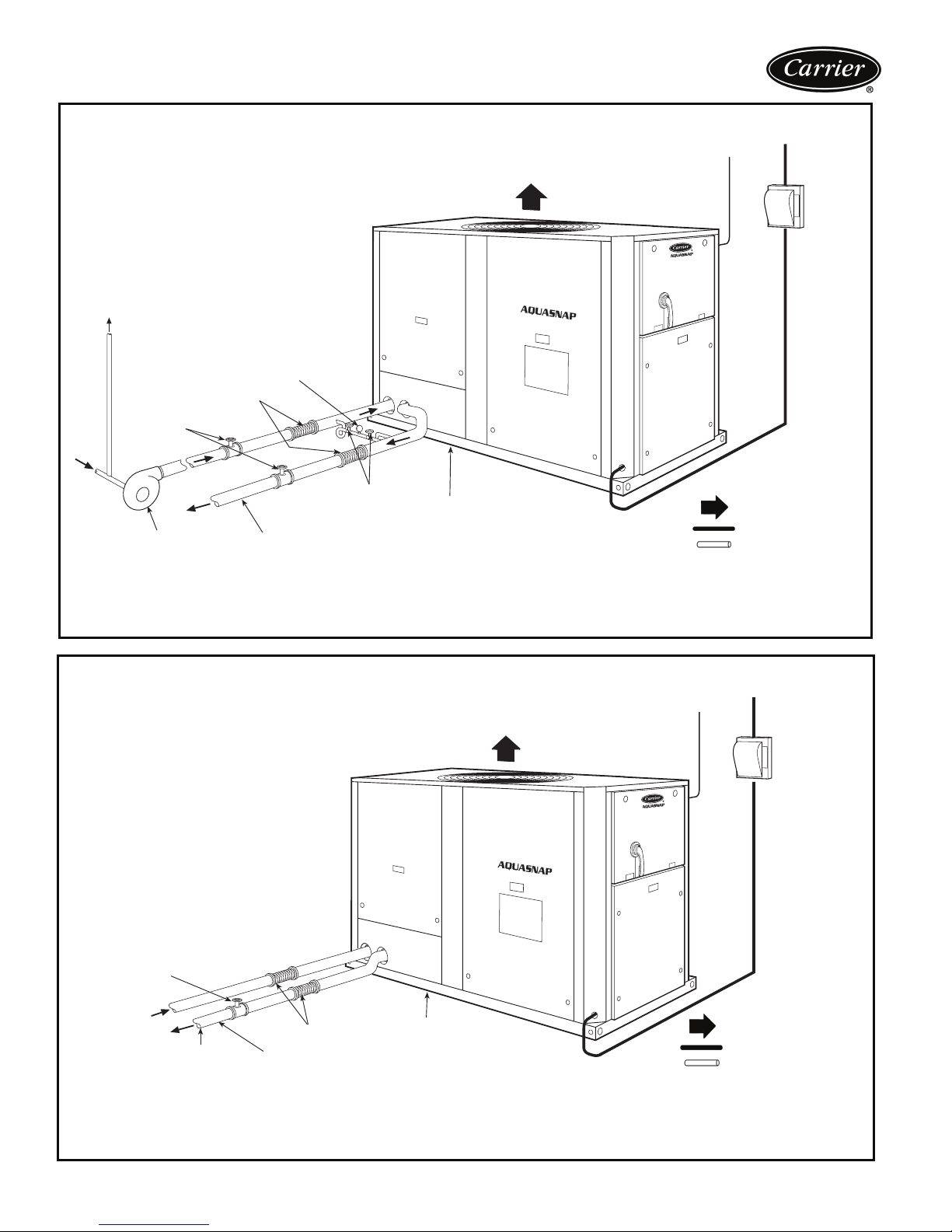
Typical piping and wiring
30RA UNITS WITHOUT HYDRONIC PACKAGE
TO
EXPANSION
TANK
VALV E
PRESSURE
GAGE
FLOW
GATE
VALV E
VIBRATION
ELIMINATOR
AIR FLOW
CONTROL
WIRING
FIELD
POWER
SUPPLY
SHUT OFF
VALV ES
PUMP
NOTES:
1. Chiller must be installed level to within 1/8 in. per foot (10.4 mm per meter) to maintain proper compressor oil retur n and hydraulics.
2. Wiring and piping shown are general points-of-connection guides only and are not intended for a specific installation. Wiring and piping shown are
for a quick overview of system and are not in accordance with recognized standards.
3. All wiring must comply with applicable local and national codes.
4. All piping must follow standard piping techniques. Refer to Carrier System Design Manual or appropriate ASHRAE (American Society of Heating,
Refrigeration, and Air Conditioning Engineers) handbook for details.
HEAT TAPE INSULATION IS RECOMMENDED ON ALL EXPOSED PIPING
IF AMBIENT TEMPERATURE <32 F (0° C) AND NO ANTIFREEZE SOLUTION IS IN SYSTEM
DRAIN
30RA UNITS WITH HYDRONIC PACKAGE
CONTROL
WIRING
AIR FLOW
LEGEND
Airflow Through Condenser
Power Wirin g
Chilled Water Piping
FIELD
POWER
SUPPLY
GATE
VALV E
FLOW
NOTE 5
NOTES:
1. Chiller must be installed level to within 1/8 in. per foot (10.4 mm per meter) to maintain proper compressor oil return and hydraulics.
2. Wiring and piping shown are general points-of-connection guides only and are not intended for a specific installation. Wiring and piping shown are for a
quick overview of system and are not in accordance with recognized standards.
3. All wiring must comply with applicable local and national codes.
4. All pi ping must follow standard piping techniques. Refer to Carrier System Design Manual or appropriate ASHRAE (American Society of Heating,
Refrigeration, and Air Conditioning Engineers) handbook for details.
5. Air separator required as close to chiller as possible (except primary/secondary systems).
HEAT TAPE INSULATION IS RECOMMENDED ON ALL EXPOSED PIPING
IF AMBIENT TEMPERATURE <32 F (0° C) AND NO ANTIFREEZE SOLUTION IS IN SYSTEM
VIBRATION
ELIMINATOR
28
DRAIN
LEGEND
Airflow Through Condenser
Powe r Wiring
Chilled Water Piping
Page 29
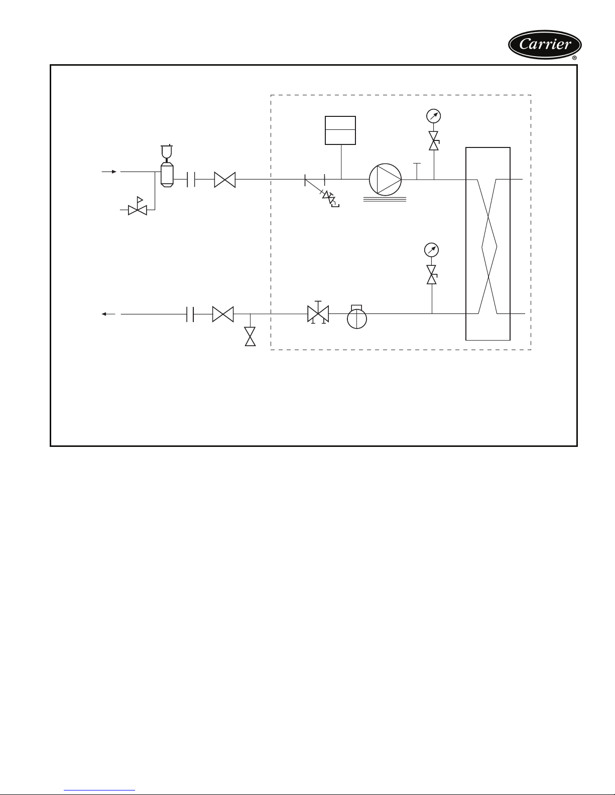
TYPICAL PIPING DIAGRAM ON 30RA UNITS WITH HYDRONIC PACKAGE
14
12
13
12
1— Strainer/Blow-Down Valve
2— Expansion Tank
3— Pump
4— Electric Heater
5— Air Vent Connection Port
6— Pressure Gages/Petcocks
7— Heat Exchanger
2
11
1
11
10
9
3
4
8
6
7
5
6
LEGEND
8— Flow Switch
9— Balance Valve/Drain Plug
10 — Pressure Relief
11 — Isolation Valves
12 — Flex Connections
13 — Pressure Reducing/Fill Valve
14 — Air Separator and Vent
--- Factory Supplied
29
Page 30
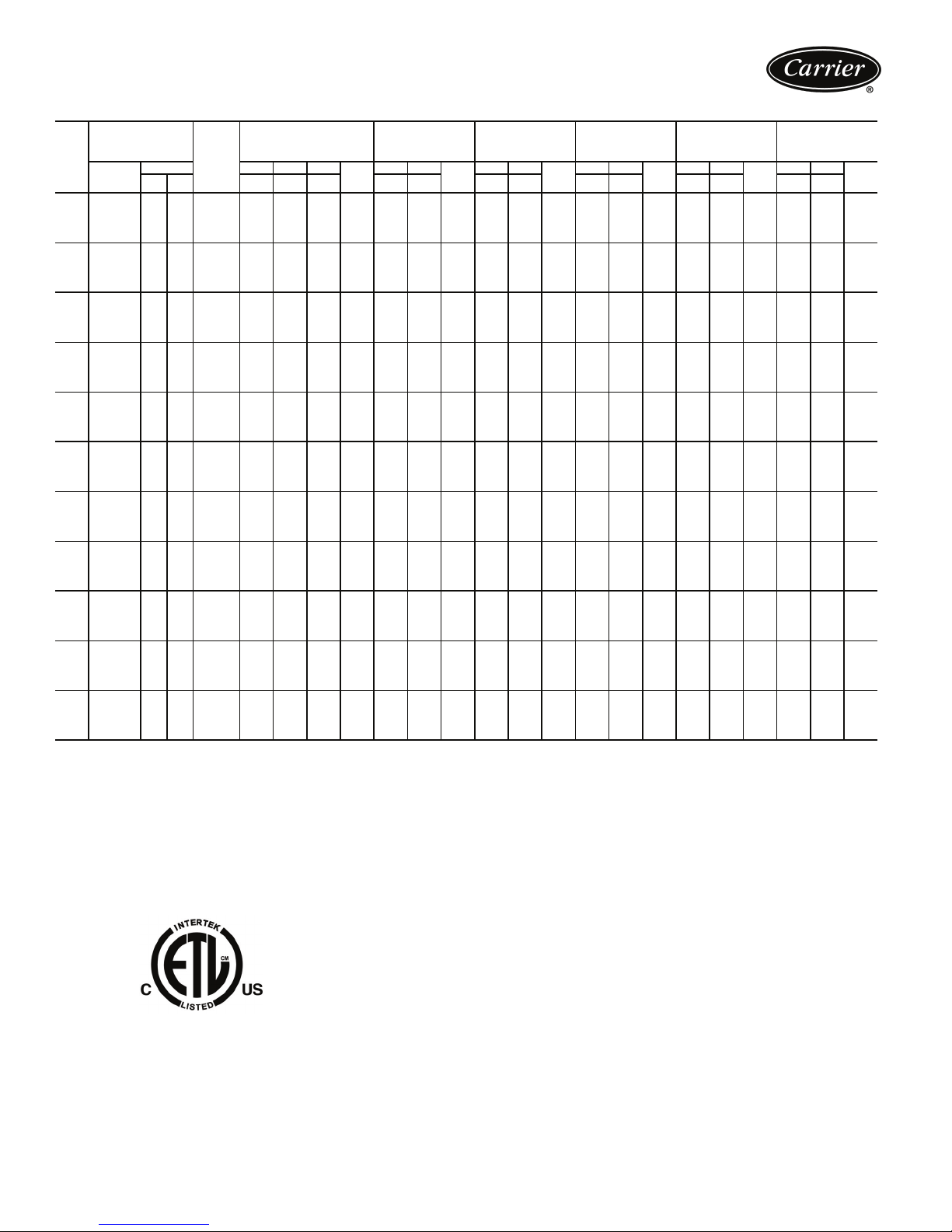
Electrical data
30RA ELECTRICAL DATA
2.0/1.5 HP
(STD) PUMP
Pump Options
‘B’ or ‘G’
MCA MOCP Rec
Fuse
Size
MCA MOCP Rec
Fuse
Size
1.5/1.0 HP PUMP
Pump Options
‘A’ or ‘F’
Fuse
Size
UNIT
30RA
ICF — Instantaneous Current Flow MOCP — Maximum Overcurrent Protection
MCA — Minimum Circuit Amps XL — Across-the-Line Start
NOTES:
1. Units are suitable for use on electrical systems where voltage supplied to the unit terminals
2. All units/modules have single point primary power connection. (Each unit/module requires
3. Cooler heater is wired into the control circuit so it is always operable as long as the power
4. Power draw control circuits include both crankcase heaters and cooler heaters (where
UNIT VOLTAGE
Supplied MCA MOCP ICF Rec
V-H z
(3 Ph)
Min Max XL XL XL XL XL XL XL XL XL XL XL XL XL
230-60 207 253 1 46.2 70 272.6 60 50.2 80 60 51.4 80 60 51.4 80 60 53.6 80 70 — — —
208/230-60 187 253 1 51.3 80 273.4 60 55.7 90 70 57.0 90 70 57.0 90 70 59.5 90 70 — — —
010
460-60 414 506 1 23.8 35 123.8 30 25.8 40 30 26.4 40 35 26.4 40 35 27.5 40 35 — — —
575-60 518 633 1 19.2 30 83.0 25 20.8 30 25 21.2 30 25 21.2 30 25 22.1 35 30 — — —
380-60 342 418 1 29.9 50 159.6 35 32.3 50 40 33.0 50 40 33.0 50 40 34.3 50 40 — — —
230-60 207 253 1 62.4 100 387.6 80 66.4 110 80 67.6 110 80 67.6 110 80 69.8 110 90 — — —
208/230-60 187 253 1 69.3 110 388.4 90 73.7 110 90 75.0 110 90 75.0 110 90 77.5 125 90 — — —
015
460-60 414 506 1 33.6 50 178.8 40 35.6 50 45 36.2 50 45 36.2 50 45 37.3 60 45 — — —
575-60 518 633 1 26.7 45 143.0 35 28.3 45 35 28.7 45 35 28.7 45 35 29.6 45 35 — — —
380-60 342 418 1 42.2 70 239.6 50 44.6 70 60 45.4 70 50 45.4 70 50 46.7 70 60 — — —
230-60 207 253 1 67.3 90 271.2 80 71.3 90 80 72.5 90 80 72.5 90 80 74.7 100 90 — — —
208/230-60 187 253 1 74.8 100 274.9 90 79.2 100 90 80.5 110 90 80.5 110 90 83.0 110 100 — — —
018
460-60 414 506 1 35.5 45 147.9 40 37.5 50 45 38.1 50 45 38.1 50 45 39.2 50 45 — — —
575-60 518 633 1 28.5 35 99.3 35 30.1 40 35 30.5 40 35 30.5 40 35 31.4 40 35 — — —
380-60 342 418 1 44.0 60 182.1 50 46.4 60 60 47.1 60 60 47.1 60 60 48.5 60 60 — — —
230-60 207 253 1 84.9 110 311.3 100 88.9 125 100 90.1 125 100 90.1 125 100 92.3 125 110 — — —
208/230-60 187 253 1 94.3 125 316.4 110 98.7 125 110 100.1 125 125 100.1 125 125 102.5 125 125 — — —
022
460-60 414 506 1 44.7 60 154.4 50 46.7 60 60 47.3 60 60 47.3 60 60 48.4 60 60 — — —
575-60 518 633 1 36.8 50 136.0 45 38.4 50 45 38.9 50 45 38.9 50 45 39.8 50 45 — — —
380-60 342 418 1 57.7 80 194.7 70 60.1 80 70 60.9 80 70 60.9 80 70 62.2 80 70 — — —
230-60 207 253 1 92.2 125 311.3 110 96.2 125 110 97.4 125 110 97.4 125 110 99.6 125 110 — — —
208/230-60 187 253 1 102.4 125 316.4 125 106.8 125 125 108.2 125 125 108.2 125 125 110.6 150 125 — — —
025
460-60 414 506 1 50.3 70 160.0 60 52.3 70 60 52.9 70 60 52.9 70 60 54.0 70 60 — — —
575-60 518 633 1 41.2 50 140.4 50 42.8 50 50 43.3 50 50 43.3 50 50 44.2 60 50 — — —
380-60 342 418 1 65.2 90 202.2 80 67.6 90 80 68.4 90 80 68.5 90 80 69.7 90 80 — — —
230-60 207 253 1 108.2 150 433.4 125 112.2 150 125 113.4 150 125 113.4 150 125 115.6 150 150 — — —
208/230-60 187 253 1 120.2 150 439.3 150 124.6 150 150 125.9 150 150 125.9 150 150 128.4 175 150 — — —
030
460-60 414 506 1 58.4 80 203.6 70 60.4 80 70 61.0 80 70 61.0 80 70 62.1 80 70 — — —
575-60 518 633 1 46.4 60 162.7 60 48.0 60 60 48.4 60 60 48.4 60 60 49.3 60 60 — — —
380-60 342 418 1 73.5 100 270.9 90 76.0 100 90 76.7 100 90 76.7 100 90 78.0 100 90 — — —
230-60 207 253 1 138.1 175 463.4 150 — — — 143.3 175 175 — — — 145.5 175 175 150.7 175 175
208/230-60 187 253 1 153.4 200 472.5 175 — — — 159.1 200 175 — — — 161.6 200 175 167.3 200 200
035
460-60 414 506 1 73.2 90 218.4 80 — — — 75.8 90 90 — — — 76.9 100 90 79.5 100 90
575-60 518 633 1 59.3 70 175.7 70 — — — 61.4 80 70 — — — 62.3 80 70 64.3 80 70
380-60 342 418 1 93.3 110 290.7 110 — — — 96.5 125 110 — — — 97.8 125 110 101.0 125 110
230-60 207 253 1 145.4 175 470.6 175 — — — 150.6 175 175 — — — 152.8 175 175 158.0 200 175
208/230-60 187 253 1 161.5 200 480.6 175 — — — 167.2 200 200 — — — 169.7 200 200 175.4 200 200
040
460-60 414 506 1 78.8 100 224.0 90 — — — 81.4 100 90 — — — 82.5 100 90 85.1 100 100
575-60 518 633 1 63.7 80 180.1 70 — — — 65.8 80 80 — — — 66.7 80 80 68.7 80 80
380-60 342 418 1 100.8 125 298.2 110 — — — 104.0 125 125 — — — 105.3 125 125 108.5 125 125
230-60 207 253 1 162.1 200 382.7 175 — — — 167.3 200 200 — — — 169.5 200 200 174.7 200 200
208/230-60 187 253 1 180.0 200 395.6 200 — — — 185.8 225 200 — — — 188.2 225 225 193.9 225 225
045
460-60 414 506 1 86.0 100 196.8 100 — — — 88.6 100 100 — — — 89.7 110 100 92.3 110 100
575-60 518 633 1 69.9 80 170.1 80 — — — 72.0 80 80 — — — 72.9 90 80 74.9 90 90
380-60 342 418 1 109.9 125 248.4 125 — — — 113.0 125 125 — — — 114.4 125 125 117.5 125 150
230-60 207 253 1 175.3 200 394.4 200 — — — 180.5 200 200 — — — 182.7 200 200 187.9 200 200
208/230-60 187 253 1 194.6 225 408.6 225 — — — 200.4 225 225 — — — 202.8 225 225 208.6 225 225
050
460-60 414 506 1 95.5 110 205.2 110 — — — 98.1 110 110 — — — 99.2 110 110 101.8 110 110
575-60 518 633 1 78.2 90 177.5 90 — — — 80.3 90 90 — — — 81.2 90 90 83.3 90 90
380-60 342 418 1 123.8 150 260.8 150 — — — 127.0 150 150 — — — 128.3 150 150 131.4 150 150
230-60 207 253 1 205.5 225 530.7 225 — — — 210.7 250 225 — — — 212.9 250 225 218.1 250 250
208/230-60 187 253 1 228.2 250 547.3 250 — — — 234.0 250 250 — — — 236.4 250 250 242.1 250 250
055
460-60 414 506 1 110.8 125 256.0 125 — — — 113.4 125 125 — — — 114.5 125 125 117.1 125 125
575-60 518 633 1 88.0 100 204.4 100 — — — 90.1 100 100 — — — 91.0 100 100 93.0 110 100
380-60 342 418 1 139.5 150 336.9 150 — — — 142.7 150 150 — — — 144.0 150 150 147.2 175 175
is not below or above the listed minimum and maximum limits. Maximum allowable phase
imbalance is: voltage, 2%; amps 10%.
its own power supply.) Main power must be supplied from a field-supplied disconnect.
supply disconnect is on, even if any safety device is open.
used). Each compressor has a crankcase heater which draws 180 watts of power.
POWER
SUPPLY
REQD.
NO HYDRONIC PACKAGE
QTY.
LEGEND
2.0/1.5 HP
(ALT) PUMP
Pump Options
‘C’ or ‘H’
MCA MOCP Rec
Fuse
Size
3.0/2.0 HP PUMP
Pump Options
‘D’ or ‘J’
MCA MOCP Rec
Fuse
Size
MCA MOCP Rec
5.0/3.0 HP PUMP
Pump Options
‘E’ or ‘K’
Fuse
Size
30
Page 31
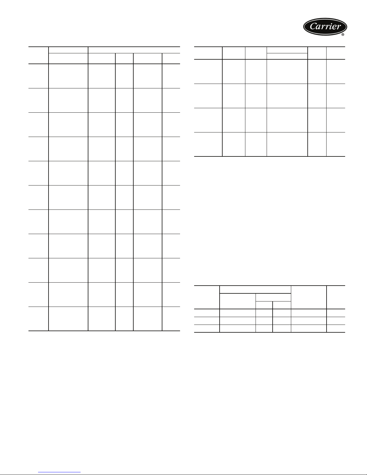
UNIT
30RA
FLA — Full Load Amps
UNIT VOLTAGE STANDARD CONDENSER FANS
V-H z ( 3 P h)
230-60 1 7.6 — —
010
015
018
022
025
030
035
040
045
050
055
208/230-60 1 8.4 — —
460-60 1 3.8 — —
575-60 1 3.0 — —
380-60 1 4.6 — —
230-60 1 7.6 — —
208/230-60 1 8.4 — —
460-60 1 3.8 — —
575-60 1 3.0 — —
380-60 1 4.6 — —
230-60 1 7.6 — —
208/230-60 1 8.4 — —
460-60 1 3.8 — —
575-60 1 3.0 — —
380-60 1 4.6 — —
230-60 2 4.8 — —
208/230-60 2 5.3 — —
460-60 2 2.4 — —
575-60 2 1.9 — —
380-60 2 2.9 — —
230-60 2 4.8 — —
208/230-60 2 5.3 — —
460-60 2 2.4 — —
575-60 2 1.9 — —
380-60 2 2.9 — —
230-60 2 4.8 — —
208/230-60 2 5.3 — —
460-60 2 2.4 — —
575-60 2 1.9 — —
380-60 2 2.9 — —
230-60 2 4.8 1 7.6
208/230-60 2 5.3 1 8.4
460-60 2 2.4 1 3.8
575-60 2 1.9 1 3.0
380-60 2 2.9 1 4.6
230-60 2 4.8 1 7.6
208/230-60 2 5.3 1 8.4
460-60 2 2.4 1 3.8
575-60 2 1.9 1 3.0
380-60 2 2.9 1 4.6
230-60 2 4.8 2 4.8
208/230-60 2 5.3 2 5.3
460-60 2 2.4 2 2.4
575-60 2 1.9 2 1.9
380-60 2 2.9 2 2.9
230-60 2 4.8 2 4.8
208/230-60 2 5.3 2 5.3
460-60 2 2.4 2 2.4
575-60 2 1.9 2 1.9
380-60 2 2.9 2 2.9
230-60 2 4.8 2 4.8
208/230-60 2 5.3 2 5.3
460-60 2 2.4 2 2.4
575-60 2 1.9 2 1.9
380-60 2 2.9 2 2.9
LEGEND
FAN ELECTRICAL DATA
Circuit A
Quantity
FLA
(each)
Circuit B
Quantity
FLA
(each)
PUMP ELECTRICAL DATA
PUMP
OPTION
‘A’ or ‘F’ 1.5 HP
‘B’, ‘C’
‘G’ or ‘H’
‘D’ or ‘J’ 3.0 HP
‘E’ or ‘K’ 5.0 HP
FLA — Full Load Amps
LRA — Locked Rotor Amps
NOTES:
1. Units are suitable for use on electrical systems where voltage supplied
to the unit terminals is not below or above the listed minimum and maximum limits. Maximum allowable phase imbalance is: voltage, 2%;
amps 10%.
2. All units/modules have single point primary power connection. (Each
unit/module requires its own power supply.) Main power must be supplied from a field-supplied disconnect.
3. The unit control circuit power transformer (24 v, single-phase for all
voltages) is factory supplied.
4. Cooler heaters are wired into the main power circuit so they are always
operable as long as the disconnect is on, even if any safety device is
open, and the unit ON/OFF switch is in the OFF position.
5. Incoming wire size ranges are shown below:
a. Size 010-030 terminal block no. 8 - no. 2/0 AWG (American
b. Size 035-055 terminal block no. 6 - 350 kcmil
c. 60 and 100 amp non-fused disconnect option no. 6 - no. 1 AWG
d. 250 amp non-fused disconnect option no. 6 AWG - 350 kcmil
PUMP
SIZE
2.0 HP
LEGEND
Wire Gage)
PUMP
RPM
3500 230-60 4.0 32.0
3500 208/230-60 4.4 36.0
3500 460-60 2.0 16.0
3500 575-60 1.6 14.4
3500 380-60 2.4 21.8
3490 230-60 5.2 42.0
3490 208/230-60 5.8 47.0
3490 460-60 2.6 21.0
3490 575-60 2.1 18.8
3490 380-60 3.1 28.4
3480 230-60 7.4 53.0
3480 208/230-60 8.2 58.0
3480 460-60 3.7 26.5
3480 575-60 3.0 25.6
3480 380-60 4.5 38.7
3450 230-60 12.6 126.0
3450 208/230-60 13.9 136.8
3450 460-60 6.3 63.0
3450 575-60 5.0 55.4
3450 380-60 7.6 83.9
UNIT VOLTAGE
V-H z ( 3 P h)
FLA
(each)
LRA
(each)
ACCESSORY TANK — ELECTRICAL DATA
30RA-
900---
V-H z
(1-Ph)
Supplied
Min Max
001 230-60 207 253 1 14.1
009 230-60 207 253 1 14.1
010 230-60 207 253 1 28.2
LEGEND
FLA — Full Load Amps
UNIT VOLTAGE
POWER
SUPPLY
QUANTITY
REQUIRED
FLA
31
Page 32

Electrical data (cont)
UNIT
30RA
010
015
018
022
025
030
035
040
045
050
055
LEGEND
LRA — Locked Rotor Amps
RLA — Rated Load Amps
UNIT VOLTAGE COMPRESSOR
V-H z ( 3 P h)
230-60 30.9265——————
208/230-60 34.3265——————
460-60 16.0120——————
575-60 12.980——————
380-60 20.2155——————
230-60 43.8380——————
208/230-60 48.7380——————
460-60 23.8175——————
575-60 18.9140——————
380-60 30.1235——————
230-60 26.6 237 26.6 237 — — — —
208/230-60 29.5 237 29.5 237 — — — —
460-60 14.1 130 14.1 130 — — — —
575-60 11.3 85 11.3 85 — — — —
380-60 17.5 160 17.5 160 — — — —
230-60 29.4 265 36.7 265 — — — —
208/230-60 32.7 265 40.8 265 — — — —
460-60 14.6 120 20.2 135 — — — —
575-60 12.2 80 16.6 120 — — — —
380-60 18.9 155 26.4 170 — — — —
230-60 36.7 265 36.7 265 — — — —
208/230-60 40.8 265 40.8 265 — — — —
460-60 20.2 135 20.2 135 — — — —
575-60 16.6 120 16.6 120 — — — —
380-60 26.4 170 26.4 170 — — — —
230-60 43.8 380 43.8 380 — — — —
208/230-60 48.7 380 48.7 380 — — — —
460-60 23.8 175 23.8 175 — — — —
575-60 18.9 140 18.9 140 — — — —
380-60 30.1 235 30.1 235 — — — —
230-60 29.4 265 36.7 265 43.8 380 — —
208/230-60 32.7 265 40.8 265 48.7 380 — —
460-60 14.6 120 20.2 135 23.8 175 — —
575-60 12.2 80 16.6 120 18.9 140 — —
380-60 18.9 155 26.4 170 30.1 235 — —
230-60 36.7 265 36.7 265 43.8 380 — —
208/230-60 40.8 265 40.8 265 48.7 380 — —
460-60 20.2 135 20.2 135 23.8 175 — —
575-60 16.6 120 16.6 120 18.9 140 — —
380-60 26.4 170 26.4 170 30.1 235 — —
230-60 30.9 265 36.7 265 30.9 265 36.7 265
208/230-60 34.3 265 40.8 265 34.3 265 40.8 265
460-60 16.0 120 20.2 135 16.0 120 20.2 135
575-60 12.9 80 16.6 120 12.9 80 16.6 120
380-60 20.2 155 26.4 170 20.2 155 26.4 170
230-60 36.7 265 36.7 265 36.7 265 36.7 265
208/230-60 40.8 265 40.8 265 40.8 265 40.8 265
460-60 20.2 135 20.2 135 20.2 135 20.2 135
575-60 16.6 120 16.6 120 16.6 120 16.6 120
380-60 26.4 170 26.4 170 26.4 170 26.4 170
230-60 43.8 380 43.8 380 43.8 380 43.8 380
208/230-60 48.7 380 48.7 380 48.7 380 48.7 380
460-60 23.8 175 23.8 175 23.8 175 23.8 175
575-60 18.9 140 18.9 140 18.9 140 18.9 140
380-60 30.1 235 30.1 235 30.1 235 30.1 235
COMPRESSOR ELECTRICAL DATA
A1 A2 B1 B2
RLA LRA RLA LRA RLA LRA RLA LRA
32
Page 33
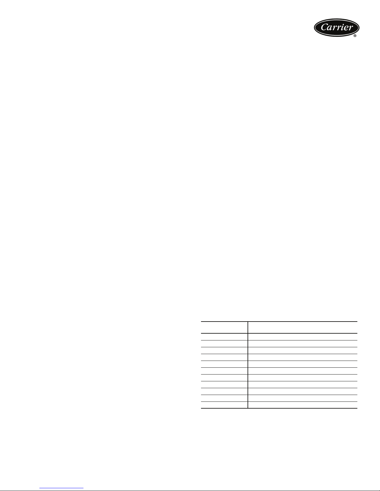
Controls
Microprocessor — The ComfortLink™ microprocessor
controls overall unit operation. Its central executive routine
controls a number of processes simultaneously. These
include internal timers, reading inputs, analog to digital
conversions, fan control, display control, diagnostic control, output relay control, demand limit, capacity control,
head pressure control, and temperature reset. Some processes are updated almost continuously, others every 2 to
3 seconds, and some every 30 seconds. The microprocessor routine is started by switching the Emergency ON-OFF
switch to ON position. Pump control of external pumps
(where so configured) or optional internal pump, will
energize the cooler pump to the internal (or CCN) time
schedule (or input occupied signal from external system).
Where dual pumps are utilized, control will also stagger
start of pumps based on last started. When the unit
receives a call for cooling (based on a deviation from chilled
water set point), the unit stages up in capacity to maintain
the cooler fluid set point. The first compressor starts 1 to
3 minutes after the call for cooling. The ComfortLink
microprocessor controls the capacity of the chiller by
cycling compressors at a rate to satisfy actual dynamic load
conditions. The control maintains leaving-fluid temperature
set point shown on the scrolling marquee display board
through intelligent cycling of compressors. Accuracy
depends on loop volume, loop flow rate, load, outdoor-air
temperature, number of stages, and particular stage being
cycled off. No adjustment for cooling range or cooler flow
rate is required, because the control automatically compensates for cooling range by measuring both return-fluid temperature and leaving-fluid temperature. This is referred to
as leaving-fluid temperature control with return-fluid temperature compensation.
The basic logic for determining when to add or remove a
stage is a time band integration of deviation from set point
plus rate of change of leaving-fluid temperature. When
leaving-fluid temperature is close to set point and slowly
moving closer, logic prevents addition of another stage. If
leaving-fluid temperature is less than 34 F (1.1 C) for
water, or 6° F (3.3° C) below the set point for brine units,
the unit is shut off until the fluid temperature goes to 34 F
(1.1 C) or to 6° F (3.3° C) above the set point to protect
against freezing.
If 1° F per minute (0.6° C per minute) pulldown control
has been selected (adjustable setting), no additional steps of
capacity are added as long as difference between leavingfluid temperature and set point is greater than 4° F (2.2° C)
and rate of change in leaving-fluid temperature is less than
1° F per minute (0.6° C per minute). If it has been less than
90 seconds since the last capacity change, compressors
will continue to run unless a safety device trips. This
prevents rapid cycling and also helps return oil during short
on periods.
Sensors — Three thermistors are used for temperaturesensing inputs to microprocessor. Additional thermistor
sensors may be used as remote temperature sensors for
optional LCWT reset.
• Cooler leaving chilled fluid temperature (T1)
• Cooler entering fluid (return) temperature (T2)
• Outside air temperature (T9)
Two refrigerant pressure transducers are used in each
circuit for sensing suction and discharge pressure. The
microprocessor uses these inputs to control capacity and
fan cycling.
• Saturated condensing temperature
• Cooler saturation temperature
The microprocessor uses these temperatures and pressures to control capacity and fan cycling.
Control sequence
Off cycle — If ambient temperature is below 36 F (2 C),
cooler heaters (if equipped) are also energized.
Start-up — After control circuit switches on, the prestart
process takes place, then microprocessor checks itself,
starts pump (if configured) and waits for temperature to
stabilize. The controlled pulldown feature limits compressor loading on start-up to reduce demand on start-up and
unnecessary compressor usage. The microprocessor limits
supply-fluid temperature decrease (start-up only) to 1° F
(0.6° C) per minute.
Capacity control — On first call for cooling, microprocessor starts initial compressor and fan stage on lead
circuit.
As additional cooling is required, additional compressors
are energized.
Speed at which capacity is added or reduced is controlled by temperature deviation from set point and rate of
temperature change of chilled fluid.
The Main Base Board (MBB) responds to temperature of
supply chilled water to cycle the compressor(s) and to control compressor unloading and loading to match cooling
load requirements.
Minimum load control valve is energized by the MBB.
Valve allows hot gas to pass directly into the cooler circuit
on the final step of unloading, maintaining constant suction pressure and permitting the unit to operate at lower
loads with less compressor cycling.
CAPACITY CONTROL STEPS
UNIT
30RA
010 0,100
015 0,100
018 0, 50, 100
022 0, 41, 100
025 0, 50, 100
030 0, 50, 100
035 0, 25, 60, 100
040 0, 32, 63, 100
045 0, 22, 44, 72, 100
050 0, 25, 50, 75, 100
055 0, 25, 50, 75, 100
STANDARD
CAPACITY STEPS (%)
33
Page 34

Controls (cont)
Standard ComfortLink™ controls with scrolling
marquee display module — A four-digit alphanumeric
display shows all of the ComfortLink control codes (with
60-character expandable clear language), plus set points,
time of day, temperatures, pressures, and superheat. Additional information can be displayed all at once with the
accessory Navigator™ display.
Low-temperature override — This feature prevents
LCWT (leaving chilled fluid temperature) from overshooting the set point and possibly causing a nuisance trip-out
by the freeze protection.
High-temperature override — This feature allows
chiller to add capacity quickly during rapid load variations.
Abnormal conditions — All control safeties in chiller
operate through compressor protection board or control
relay and microprocessor.
Loss of feedback signal to the MBB will cause the compressor(s) to shut down. For other safeties, microprocessor
makes appropriate decision to shut down a compressor
due to a safety trip or bad sensor reading and displays
appropriate failure code on the display. Chiller holds in
safety mode until reset. It then reverts to normal control
when unit is reset.
Low-pressure safety — Safety cuts out if system pressure drops below minimum.
High-pressure cutout — Switch shuts down compressors if compressor discharge pressure increases to
426 psig (2937 kPa).
Compressor anti-cycling — This feature limits compressor cycling.
Loss of flow protection — Proof of flow switches are
standard and installed on all 30RA chillers.
Sensor failures — Failures are detected by the
microprocessor.
Dual chiller control — The ComfortLink controller
allows 2 chillers (piped in parallel) to operate as a single
chilled water plant with standard control functions coordinated through the master chiller controller. This standard
ComfortLink feature requires a communication link
between the 2 chillers and an additional thermistor and
well in the common supply line.
Temperature reset — If applied, microprocessor compares either return fluid, space temperature, or outdoor-air
temperature with the accessory board settings, and adjusts
LCWT appropriately. The energy management module
can also be added for 4 to 20 mA reset.
Accessory controls — Demand can be limited by controlling the chiller capacity through the demand limit
control (the energy management module is required for
this function). This FIOP/accessory interfaces with microprocessor to control unit so that chiller’s kW demand does
not exceed its setting. It is activated from an external
switch or a 4 to 20 mA signal.
The standard ComfortLink control is programmed to
accept various accessory temperature reset options (based
on outdoor-air temperature [std], return-fluid temperature,
or space temperature), that reset the LCWT. An accessory
thermistor (T10) is required if outdoor-air temperature or
space temperature reset is selected. The energy
management module (EMM) is only required for temperature reset that is initiated by a 4 to 20 mA signal.
Demand limit — If applied, the demand limit function
limits the total power draw of unit to selected point by controlling number of operational compressors during periods
of peak electrical demand.
The energy management module is required for either 2-
stage or 4 to 20 mA demand limit.
Navigator display module — An optional 4-line,
20-character per line display an also available as a fieldinstalled accessory.
Thermostatic expansion valve (TXV) — The TXV
controls refrigerant flow to the cooler for different operating conditions. An equalization line and temperaturecontrolled sensing bulb are used to maintain a fixed setting
of super-heated refrigerant leaving the cooler.
Diagnostics — The microprocessor may be put through
a service test (see Controls, Start-Up, Operation, Service,
and Troubleshooting literature). Service test confirms
microprocessor is functional, informs observer through display the condition of each sensor and switch in chiller, and
allows observer to check for proper operation of fans and
compressors.
Default settings — To facilitate quick start-ups, 30RA
chillers with ComfortLink controls are pre-configured with
a default setting that assumes stand-alone operation supplying 44 F (6.7 C) chilled water.
Configuration settings will be based on any options
or accessories included with the unit at the time of
manufacturing.
Date and time are set to U.S.A. Eastern Time zone and
will need reconfiguring based on location and local time
zone. If operation based on occupancy scheduling is
desired, this will also need to be set during installation.
Ice duty — ComfortLink controls have the capability of
reduced leaving fluid temperature operation for thermal
storage, or ice duty. The optional energy management
module includes input contacts for the “ice done” signal
generated by the thermal storage control system. The ice
duty feature may be configured to start on an external
input command or by the ComfortLink standard internal
scheduling function. The ice duty function requires brine
modification for leaving fluid temperatures below 40 F
(4.4 C). Ice duty may be used in combination with any
other standard features offered by the energy management
module and ComfortLink controls.
The production of ice, which is stored for peak cooling
demands, can significantly decrease energy costs. The unit
produces ice (normally at night) by supplying ice storage
tanks with low temperature cooling fluid. The chiller takes
advantage of reduced ambient conditions at night for icemaking mode, so the capacity suffers a lower penalty for
the low leaving fluid temperatures.
At peak cooling demands the chiller and the stored ice
may share the cooling load to reduce operating costs. The
thermal storage system may potentially reduce the size of
the chiller plant required to meet demand loads.
34
Page 35
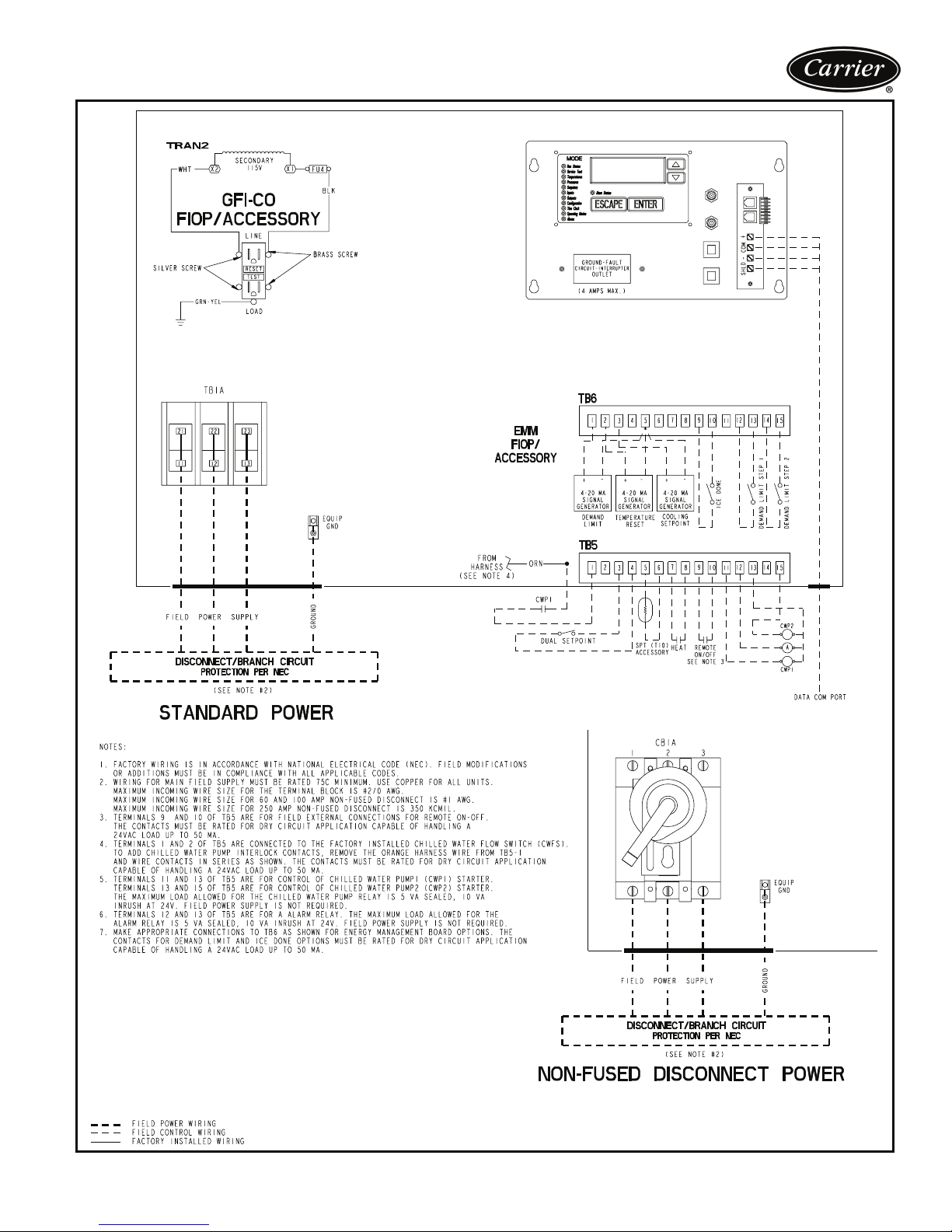
Typical control wiring schematic (30RA010-030)
LEGEND
A—Alarm
AWG — American Wire Gage
CWP — Chilled Water Pump
CWPI — Chilled Water Pump Interlock
EMM — Energy Management Module
GFI-CO — Ground Fault Interrupt Convenience Outlet
FIOP — Factory-Installed Option
NEC — National Electric Code
SPT — Space Temperature
TB — Te rm in al Bl ock
a30-4606
35
Page 36
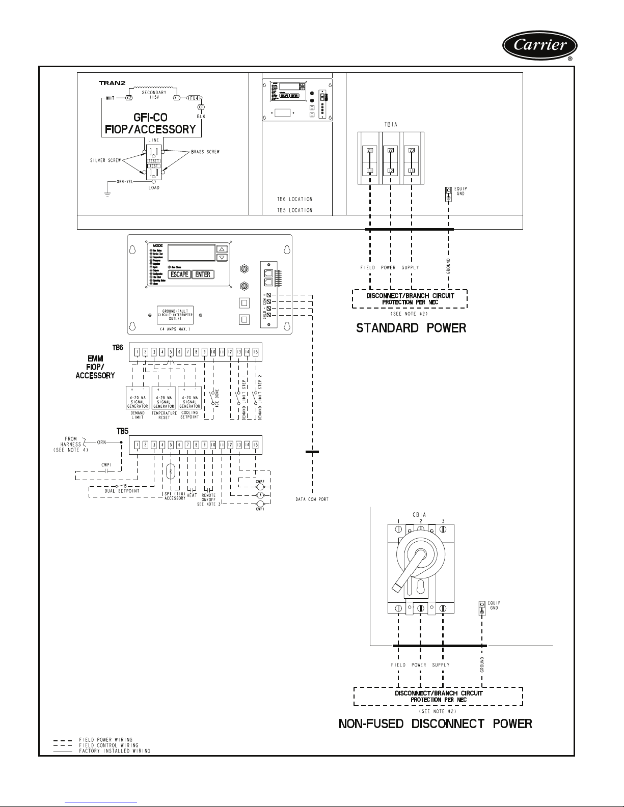
Typical control wiring schematic (30RA035-055)
NOTES:
1. FACTORY WIRING IS IN ACCORDANCE WITH NATIONAL ELECTRICAL CODE (NEC). FIELD MODIFICATIONS OR ADDITIONS MUST BE IN COMPLIANCE WITH ALL APPLICABLE CODES.
2. WIRING FOR MAIN FIELD SUPPLY MUST BE RATED 75C MINIMUM. USE COPPER FOR ALL UNITS. MAXIMUM INCOMING WIRE SIZE FOR THE TERMINAL BLOCK IS 350 KCMIL. MAXIMUM INCOMING WIRE SIZE
FOR 100 AMP NON-FUSED DISCONNECT IS #1 AWG. MAXIMUM INCOMING WIRE SIZE FOR 250 AMP
NON-FUSED DISCONNECT IS 350 KCMIL.
3. TERMINALS 9 AND 10 OF TB5 ARE FOR FIELD EXTERNAL CONNECTIONS FOR REMOTE ON-OFF. THE
CONTACTS MUST BE RATED FOR DRY CIRCUIT APPLICATION CAPABLE OF HANDLING A 24 VAC LOAD
UP TO 50 MA.
4. TERMINALS 1 AND 2 OF TB5 ARE CONNECTED TO THE FACTORY INSTALLED CHILLED WATER FLOW
SWITCH (CWFS). TO ADD CHILLED WATER PUMP INTERLOCK CONTACTS, REMOVE THE ORANGE HARNESS WIRE FROM TB5-1 AND WIRE CONTACTS IN SERIES AS SHOWN. THE CONTACTS MUST BE RATED
FOR DRY CIRCUIT APPLICATION CAPABLE OF HANDLING A 24VAC LOAD UP TO 50 MA.
5. TERMINALS 11 AND 13 OF TB5 ARE FOR CONTROL OF CHILLED WATER PUMP 1 (CWP1) STARTER. TERMINALS 13 AND 15 OF TB5 ARE FOR CONTROL OF CHILLED WATER PUMP 2 (CWP2) STARTER. THE MAXIMUM LOAD ALLOWED FOR THE CHILLED WATER PUMP RELAY IS 5 VA SEALED, 10 VA INRUSH AT 24 V.
FIELD POWER SUPPLY IS NOT REQUIRED.
6. TERMINALS 12 AND 13 OF TB5 ARE FOR AN ALARM RELAY. THE MAXIMUM LOAD ALLOWED FOR THE
ALARM RELAY IS 5 VA SEALED, 10 VA INRUSH AT 24 V. FIELD POWER SUPPLY IS NOT REQUIRED.
7. MAKE APPROPPRIATE CONNECTIONS TO TB6 AS SHOWN FOR ENERGY MANAGEMENT BOARD
OPTIONS. THE CONTACTS FOR DEMAND LIMIT AND ICE DONE OPTIONS MUST BE RATED FOR DRY CIRCUIT APPLICATION CAPABLE OF HANDLING A 24VAC LOAD UP TO 50MA.
LEGEND
A—Alarm
AWG — American Wire Gage
CWP — Chilled Water Pump
CWPI — Chilled Water Pump Interlock
EMM — Energy Management Module
GFI-CO — Ground Fault Interrupt Convenience Outlet
FIOP — Factory-Installed Option
NEC — National Electric Code
SPT — Space Temperature
TB — Terminal Block
36
a30-4607
Page 37
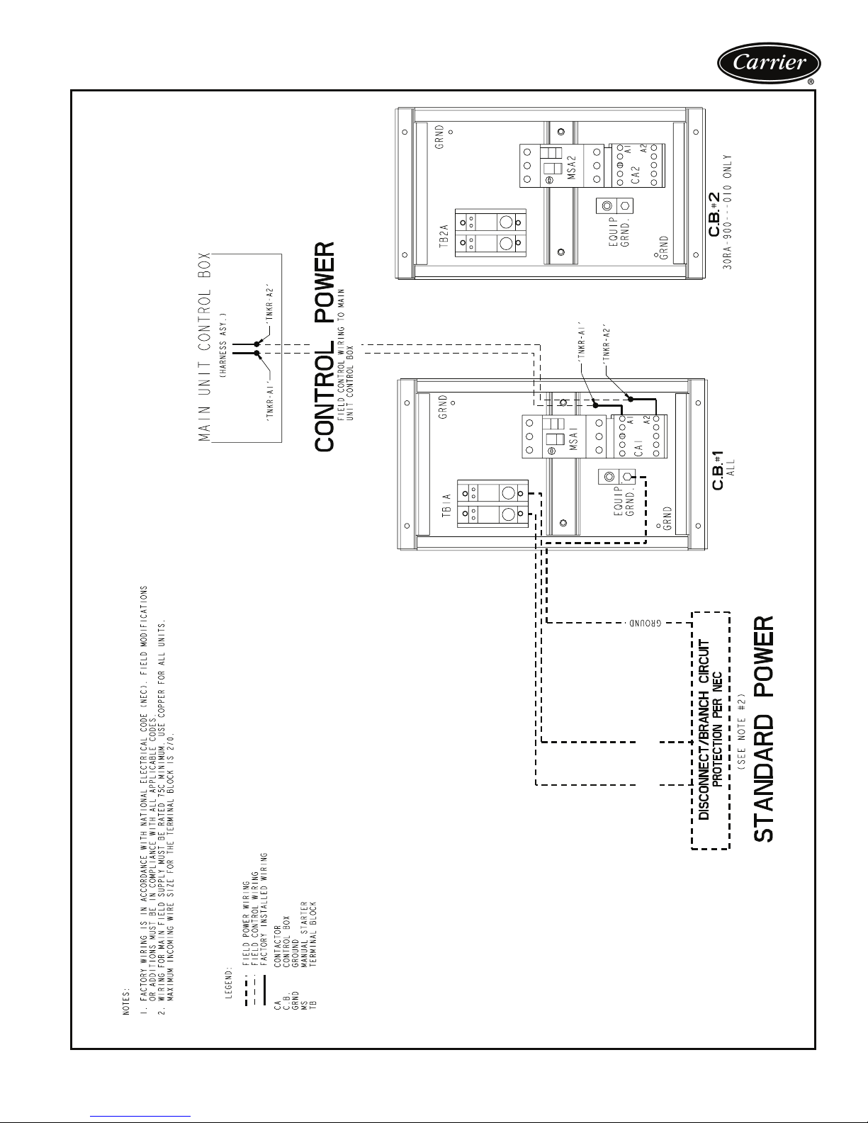
Typical control wiring schematic (storage tank)
230-1-60
FIELD POWER SUPPLY
37
Page 38
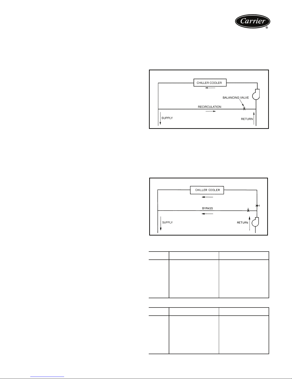
Application data
Chiller location
Do not locate near sound sensitive areas without proper
acoustic consideration. Pad isolated from building rooftop
mounting requires consideration for structure-borne transmission. Unit must be level within
1
/8-in. per ft when
installed to ensure proper oil return to the compressors.
Clearances must be provided around chillers for airflow,
service and local code requirements. See dimensional
drawings for specific unit clearance requirements. Chiller
fan discharge must be at or above adjacent solid walls.
Installation in pits is not recommended.
Oversizing chillers
Oversizing chillers by more than 15% at design conditions
must be avoided as the system operating efficiency is
adversely affected (resulting in greater or excessive electrical demand). When future expansion of equipment is
anticipated, install a single chiller to meet present load
requirements and add a second chiller to meet the additional load demand. It is also recommended that 2 smaller
chillers be installed where operation at minimum load is
critical. The operation of a smaller chiller loaded to a
greater percentage over minimum is preferred to operating
a single chiller at or near its minimum recommended value.
Minimum Load Control should not be used as a means to
allow oversizing chillers. Minimum Load Control should be
given consideration where substantial operating time is
anticipated below the minimum unloading step.
Cooler fluid temperature
1. Maximum leaving chilled fluid temperature (LCWT)
for unit is 60 F (16 C). Unit can start and pull down
with up to 95 F (35 C) entering-fluid temperature. It is
recommended that entering-fluid temperature not
exceed 70 F (21 C).
2. Minimum LCWT for standard unit is 40 F (3.3 C). For
leaving-fluid temperatures from 34 to 39.9 F (1° to
3.28 C) a 20% anti-freeze solution, or greater is
required. Application of chiller within the 39.9 to
15 F (3.3 to –9.4 C) range is possible by ordering the
factory-installed ‘brine’ option.
NOTE: Water flowing through cooler should not exceed
100 F (38 C).
Cooler flow/range
Ratings and performance data in this publication are for a
cooling temperature rise of 10° F (6° C), and are suitable
for a range from 5 to 20 F (2.8 to 11.1 C) temperature rise
without adjustment. The 30RA chillers may be operated
using a different temperature range, provided flow limits
are not exceeded. For minimum flow rates, see Minimum
and Maximum Cooler Flow Rates table. High flow rate is
limited by pressure drop that can be tolerated. Use the
Packaged Chiller Builder Program to obtain the rating if a
temperature rise other than 10° F (6° C) is used.
Minimum cooler flow (maximum cooler temperature rise) — The minimum cooler flow for standard units
is shown in Minimum and Maximum Cooler Fluid Flow
Rates table. When system design conditions require a
lower flow (or higher rise) than the minimum allowable
cooler flow, follow the recommendations below.
1. Multiple smaller chillers may be applied in series, each
providing a portion of the design temperature rise.
2. Cooler fluid may be recirculated to raise the flow rate
to the chiller. However, the mixed temperature entering cooler must be maintained a minimum of at least
5° F (2.8° C) above the LCWT.
NOTE: Recirculation flow is shown below.
RECIRCULATION FLOW
a30-4042
Maximum cooler flow — The maximum cooler flow
(approximately 5° F [2.8° C] rise) results in a practical maximum pressure drop through cooler.
Return fluid may bypass the cooler to keep the pressure
drop through the cooler within acceptable limits. This permits a higher delta T with lower fluid flow through cooler
and mixing after the cooler.
NOTE: Bypass flow is shown below.
BYPASS FLOW
a30-533
MINIMUM AND MAXIMUM COOLER FLOW RATES
ENGLISH
30RA
SIZE
010 12 46
015 16 66
018 19 76
022 25 98
025 29 114
030 33 131
035 42 167
040 45 181
045 52 206
050 57 227
055 65 260
30RA
SIZE
010 0.76 2.90
015 1.01 4.16
018 1.20 4.79
022 1.58 6.18
025 1.83 7.18
030 2.08 8.25
035 2.65 10.52
040 2.84 11.40
045 3.28 12.98
050 3.59 14.30
055 4.10 16.38
MIN. FLOW
RATE (Gpm)
MIN. FLOW
RATE (L/s)
SI
MAX. FLOW
RATE (Gpm)
MAX. FLOW
RATE (L/s)
38
Page 39
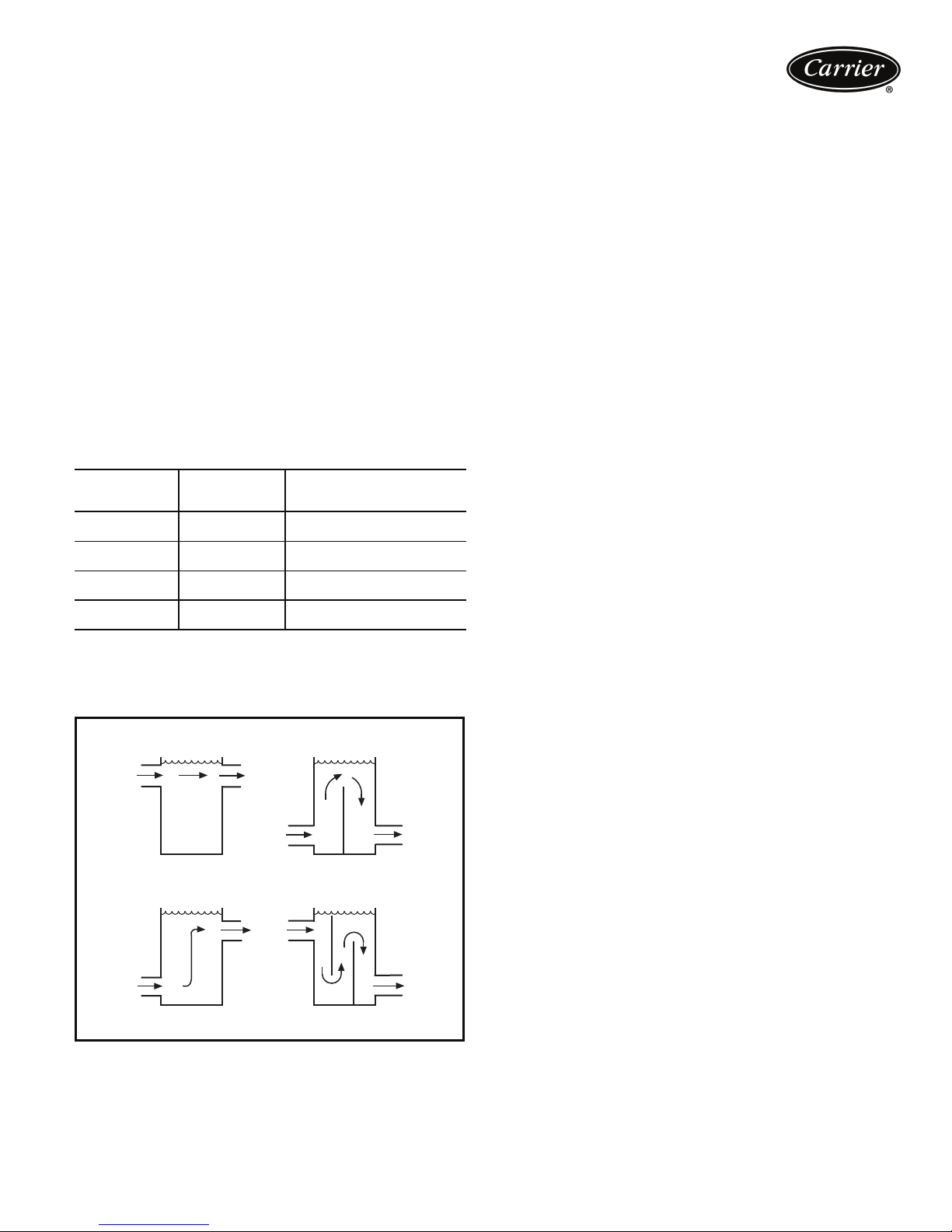
Variable cooler flow rates
Variable rates may be applied to standard chiller. Unit will,
however, attempt to maintain a constant leaving chilled
fluid temperature. In such cases, minimum flow must be in
excess of minimum flow given in Minimum and Maximum
Cooler Flow Rates table on page 38 and Minimum Fluid
Volume in Circulation table below. Flow rate must also
change in steps of less than 10% per minute. Apply 6 gal.
per ton (6.5 L per kW) water loop volume minimum if flow
rate changes more rapidly.
Fluid loop volume
The minimum volume of fluid required to be in circulation
is a function of the number of compressors in the chiller as
well as the type of application. The minimum fluid in circulation must equal or exceed the values in the following table. Note that in process cooling applications, or for operation at ambient temperatures below 32 F (0° C) with low
loading conditions, there should be more volume than is required for normal air-conditioning applications.
MINIMUM FLUID VOLUME IN CIRCULATION
UNIT
30RA010-015
30RA018-030
30RA035-040
30RA045-055
NORMAL AIR
CONDITIONING
APPLICATION
12 gal/ton
(13 L per kW)
6 gal/ton
(6.5 L per kW)
4 gal/ton
(4.3 L per kW)
3 gal/ton
(3.3 L per kW)
To achieve this fluid volume, it is often necessary to install
a tank in the loop. The tank should be baffled to ensure
there is no stratification and that water (or brine) entering
the tank is adequately mixed with liquid in the tank.
TANK INSTALLATION
BAD
BAD
PROCESS COOLING OR
LOW AMBIENT OPERATION
APPLICATION
12 gal/ton (13 L per kW)
10 gal/ton (11 L per kW)
8 gal/ton (8.7 L per kW)
6 gal/ton (6.5 L per kW)
GOOD
GOOD
Tank vo lume
A properly baffled storage tank is available as an accessory.
These tanks are designed to physically fit beneath the
corresponding 30RA unit, taking up the same footprint.
Available volume is as follows:
30RA010-018 110 gallons (416 liters)
30RA022-030 152 gallons (575 liters)
30RA035-055 305 gallons (1155 liters)
NOTE: This tank requires a separate 230/1/60 power
source.
Strainers
A strainer with a minimum of 20 mesh must be installed in
the cooler fluid inlet line, just ahead of (and as close as possible) to the cooler.
Water system overview (closed loop systems
only)
The 30RA chillers are designed for use with closed systems, meaning that there is no more than one water-air
interface in the water loop. Cooling tower loops, for example, have two water-air interfaces (sump and nozzles) and
would thus be classified as open, whereas a correctly
designed chilled water loop with the only water-air interface being in the expansion tank is closed. Since closed
and open water systems behave very differently, the following assumes that the chilled water loop is closed. A system
installed incorrectly such that air is not handled properly —
pipe leaks, vent leaks, air in pipes, etc. — may behave as
an open system and thus have unsatisfactory operation.
Pump seal wear can also cause leaks that cause poor system operation.
Proper closed system design and installation procedures
should be followed closely. The system must be constructed with pressure tight components and thoroughly
tested for installation leaks. Factory-supplied hydronic systems are available with single or dual (for back-up) pumps.
The factory-installed system includes all of the components
within the dashed lines shown in the figure on page 29.
Installation of water systems should follow sound engineering practice as well as applicable local and industry
standards. Improperly designed or installed systems may
cause unsatisfactory operation and/or system failure. Consult a water treatment specialist or appropriate literature
for information regarding filtration, water treatment, and
control devices. A typical installation with components that
might be installed with the hydronic package of the 30RA
unit is shown on page 29. A typical dual pump package for
the 010-030 size models is shown on page 40.
It is recommended that isolation (shut-off) valves be placed
exterior to the unit to allow removal and service of the
entire pump assembly, if necessary. Also, if the unit is isolated with valves, a properly sized pressure relief valve
should be installed in the piping between the unit and the
valves, following all applicable state and local codes.
39
Page 40
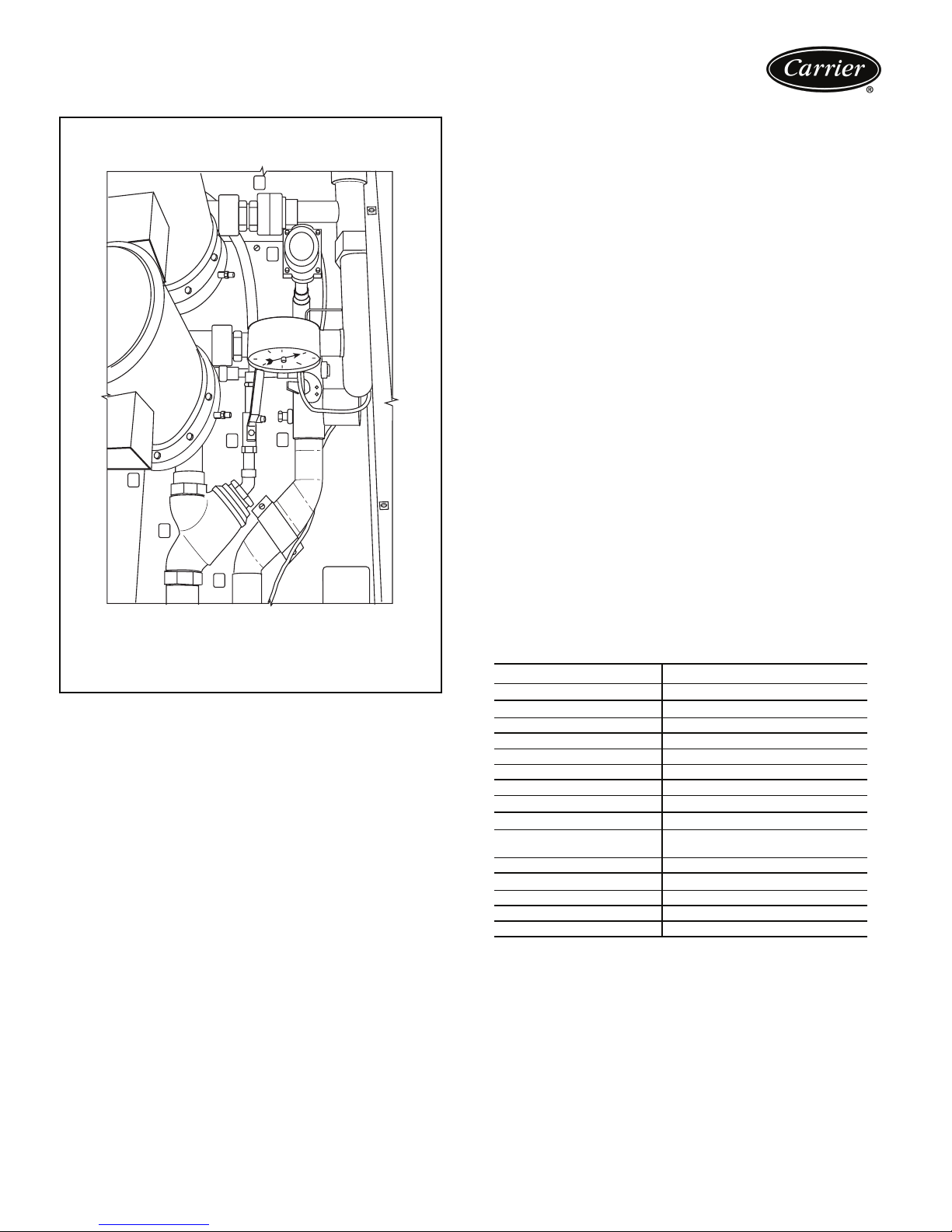
Application data (cont)
TYPICAL DUAL PUMP PACKAGE
3
5
2
7
1
6
1—Strainer
2—Blow-Down Valve
3—Discharge Check Valve
(Dual Pumps Only)
4—Balancing Valve with Drain Plug
LEGEND
Water system cleaning
Proper water system cleaning is of vital importance. Excessive particulates in the water system can cause excessive
pump seal wear, reduce or stop flow, and cause damage of
other components. Water quality should be maintained
within the limits indicated in the Water Quality Characteristics and Limitations Table.
1. Install a temporary bypass around the chiller to avoid
circulating dirty water and particulates into the pump
package and chiller during the flush. Use a temporary
circulating pump during the cleaning process. Also,
be sure that there is capability to fully drain the system after cleaning.
2. Be sure to use a cleaning agent that is compatible
with all system materials. Be especially careful if the
system contains any galvanized or aluminum components. Both detergent-dispersant and alkaline-dispersant cleaning agents are available.
3. It is a good idea to fill the system through a water
meter. This provides a reference point for the future
for loop volume readings, but it also establishes the
correct quantity of cleaner needed in order to get the
required concentration.
4
5—Flow Switch
6—Field Connections
7—Heater
4. Use a feeder/transfer pump to mix the solution and
fill the system. Circulate the cleaning system for the
length of time recommended by the cleaning agent
manufacturer.
a. After cleaning, drain the cleaning fluid and flush
the system with fresh water.
b. A slight amount of cleaning residue in the system
can help keep the desired, slightly alkaline, water
pH of 8 to 9. Avoid a pH greater than 10, since
this will adversely affect pump seal components.
c. A side stream filter is recommended during the
cleaning process. Filter side flow rate should be
enough to filter the entire water volume every 3 to
4 hours. Change filters as often as necessary during the cleaning process.
d. Remove temporary bypass when cleaning is
complete.
A strainer with a blow-down valve is standard on all 30RA
units, both with and without hydronic packages. The blowdown valve allows removal of particulates caught in the
strainer without complete removal of the screen. A female
NPT connection is provided on the valve, allowing hose
connection for drainage outside the unit.
The ComfortLink™ controls provided have a built-in feature to remind building owners or operators to clean the
strainer by discharging the blow-down valve at a pre-set
time interval. Properly installed and cleaned systems will
rarely need the strainer cleaned after the initial fill. This
time interval is user-configurable.
WATER QUALITY CHARACTERISTICS
WATER CHARACTERISTIC QUALITY LIMITATION
Alkalinity (HCO
Sulfate (SO
HCO
Electrical Conductivity 10 – 500 μS/cm
pH 7.5 – 9.0
Ammonium (NH
Chorides (Cl
Free chlorine (Cl
Hydrogen Sulfide (H
Free (aggressive) Carbon
Dioxide (CO
Total Hardness (dH) 4.0 – 8.5
Nitrate (NO
Iron (Fe) Less than 0.2 ppm
Aluminum (Al) Less than 0.2 ppm
Manganese (Mn) Less than 0.1 ppm
*Sulfides in the water quickly oxidize when exposed to air, requiring that no
agitation occur as the sample is taken. Unless tested immediately at the
site, the sample will require stabilization with a few drops of one Molar
zinc acetate solution, allowing accurate sulfide determination up to 24
hours after sampling. A low pH and high alkalinity cause system prob-
lems, even when both values are within the ranges shown. The term pH
refers to the acidity, basicity, or neutrality of the water supply. Below 7.0,
the water is considered to be acidic. Above 7.0, water is considered to be
basic. Neutral water contains a pH of 7.0.
†Dissolved carbon dioxide can either be calculated from the pH and total
alkalinity values, shown below, or measured on the site using a test kit.
Dissolved Carbon Dioxide, PPM = TA x 2
linity, PPM as CaCO3.
2-
) Less than 70 ppm
4
-
2-
/SO
3
4
-
) Less than 300 ppm
)†
2
) Less than 100 ppm
3
AND LIMITATIONS
-
) 70 – 300 ppm
3
Greater than 1.0
) Less than 2 ppm
3
) Less than 1 ppm
2
S)* Less than 0.05 ppm
2
Less than 5 ppm
[(6.3-pH)/0.3]
where TA = Total Alka-
40
Page 41
Cooler fouling factor
The fouling factor used to calculate tabulated ratings was
0.00010 ft
ing factor is increased, unit capacity decreases and compressor power increases. Standard ratings should be
corrected using the multipliers in the following table.
FOULING
(English)
(ft
2
⋅ hr ⋅ °F/Btu (0.000018 m2 ⋅ °C/W). As foul-
FOULING FACTORS
FACTOR
2
⋅hr⋅F/Btu)
.00025 .000044 0.991 0.995
.00050 .000088 0.977 0.987
.00075 .000132 0.955 0.979
.00175 .000308 0.910 0.952
FOULING
FACTOR
(SI)
(m2⋅C/kW
CAPACITY
MULTIPLIER
COMPRESSOR
POWER
MULTIPLIER
Cooler and hydronic system freeze protection
Freeze protection for down to –20 F (–28.9 C) for the
cooler and hydronic package is available as a factoryinstalled option. Since power is sometimes lost for extended periods during winter storms, freeze protection provided by heater tapes will be effective only if a back-up power
supply can be assured for the unit’s control circuit, heater
and cooler pump. If not protected with an antifreeze solution, draining the cooler and outdoor piping is recommended if the system will not be used during freezing
weather conditions.
Two conditions that must be considered when determining antifreeze concentration are leaving water set point
and ambient freeze conditions. Both of these parameters
can help determine the recommended concentration level.
Higher concentration must be used to adequately protect
the machine.
NOTE: Use only antifreeze solutions approved for heat exchanger duty.
For applications in which the leaving water temperature
set point is less than 40 F (4.4 C), a suitable inhibited antifreeze solution must be used. The solution concentration
must be sufficient to protect the chilled water loop to a
freeze protection (first crystals) concentration of at least
15° F (8.3º C) below the leaving water temperature set
point.
If the chiller refrigerant or fluid lines are in an area where
ambient conditions fall below 34º F (1º C), it is required
that an antifreeze solution be added to protect the unit and
fluid piping to a temperature of 15º F (8.3º C) below the
lowest anticipated ambient temperature.
Select concentration based on either burst or freeze protection as dictated by the application. If the chiller does not
operate during the winter, nor is a start-up expected, a
burst protection concentration is recommended. This concentration may not be high enough to pump the fluid
through the unit. Burst protection is typically a lower concentration that will provide better performance from the
machine. If the chiller does operate during winter, a freeze
protection concentration is recommended. This
concentration will be high enough to keep the fluid in a
condition that it can be pumped at low ambient conditions.
IMPORTANT: Glycol anti-freeze solutions are highly
recommended since heater tapes provide no protection in the event of a power failure.
Consult glycol fluid manufacturers for burst protection
recommendations and fluid specifications.
High ambient temperature operation
High outdoor ambient chiller start-up and operation (fully
loaded) is possible for standard 30RA chillers at ambient
temperatures up to 120 F (50 C) at nominal voltage.
Low ambient temperature operation
Units will start and operate down to 45 F (7.2 C) (sizes
010-018) and 32 F (0° C) (sizes 022-055) as standard.
Operation to –20 F (–29 C) requires optional Motor-
®
master
V condenser head pressure control as well as wind
baffles, minimum load control, and the accessory liquid line
solenoid. Inhibited propylene glycol or other suitable corrosion-resistant anti-freeze solution must be field supplied
and installed in all units for unit operation below 32 F
(0° C). Solution must be added to fluid loop to protect loop
down to 15° F (8° C) below minimum operating ambient
temperature. Concentration should be based on expected
minimum temperature and either “Burst” or “Freeze” protection levels. At least 6 gal. per ton (6.5 L per kW) of fluid
volume is the recommended minimum for a moderate system load.
NOTE: In order for a chiller to operate at –20 F (–29 C)
ambient temperature, the minimum load on the chiller
must be above the minimum step of unloading.
NOTE: As an alternative to requiring a glycol solution, the
cooler may be remotely located. Burying refrigerant lines is
never permitted.
Altitude correction factors
Correction factors must be applied to standard ratings
at altitudes above 2000 ft (610 m) using the following
multipliers:
ALTITUDE CORRECTION FACTORS
ALTITUDE
(ft)
2,000 610 0.99 1.01
4,000 1220 0.98 1.02
6,000 1830 0.97 1.03
8,000 2440 0.96 1.04
10,000 3050 0.95 1.05
ALTITUDE
(m)
CAPACITY
MULTIPLIER
COMPRESSOR
POWER
MULTIPLIER
Freeze versus burst protection
If chiller operation is not required during winter/off season,
lower glycol concentrations based on “burst” protection
criteria should be considered. Often use of burst protection
results in lower fluid costs and has less impact on chiller
cooler capacity and flow rate. Consult glycol fluid manufacturers for burst protection recommendations and fluid
specifications.
41
Page 42
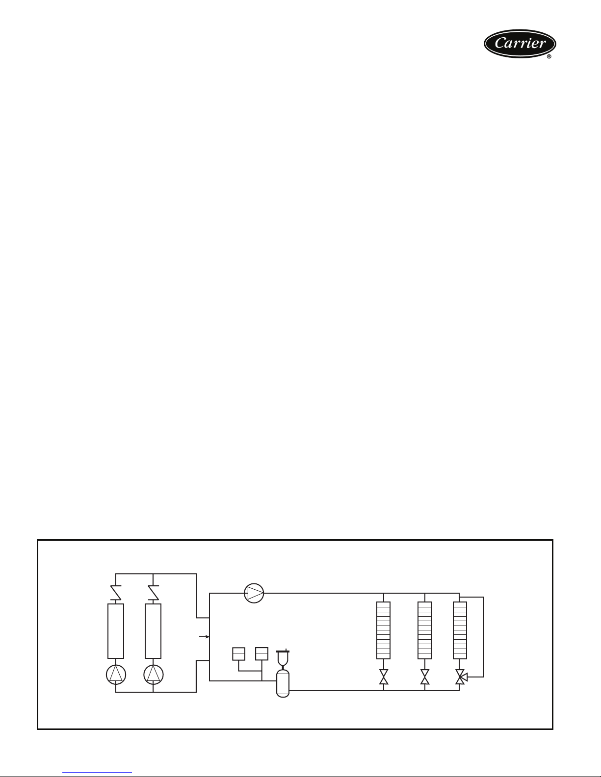
Application data (cont)
Multiple chillers
Where chiller capacities greater than 55 tons (180 kW) are
required, or where standby capability is desired, chillers
may be installed in parallel. The flow must be balanced
according to the recommendations for each chiller.
Where applied in parallel with optional hydronic package, expansion tank must be disconnected and a single
expansion tank must be installed in the system.
Unit software is capable of controlling two units as a single plant. Refer to Controls, Start-Up, Operation, Service,
and Troubleshooting guide for further details. Hydronic
pump package may not be applied in series applications.
Condenser coil protection (Enviro-Shield™)
Refer to the Environmental Corrosion Protection white
paper for more information.
Pre-coated aluminum-fin coils have a durable epoxyphenolic coating applied to the fin prior to the fin stamping
process to provide protection in mildly corrosive coastal
environments. Pre-coated coils have an inert barrier
between the aluminum fin and copper tube. This barrier
electrically disconnects the dissimilar metals to minimize
the potential for galvanic corrosion. This economical
option provides substantial corrosion protection beyond
the standard uncoated coil construction.
Copper-fin coils provide increased corrosion resistance
in moderate coastal environments where industrial air pollution is not present. All-copper coils eliminate bimetallic
construction to eliminate the potential for galvanic corrosion. Application in industrial environments is not recommended due to potential attack from sulfur, sulfur oxide,
nitrogen oxides, carbon and several other industrial airborne contaminants. In moderate seacoast environments,
copper-fin coils have extended life compared to standard
or pre-coated aluminum-fin coils.
E-coated aluminum-fin coils have an extremely flexible
and durable epoxy coating uniformly applied to all coil
surfaces. Unlike brittle phenolic dip and bake coatings,
e-coat provides superior protection with unmatched flexibility, edge coverage, metal adhesion, thermal performance and most importantly, corrosion resistance.
E-coated coils provide this protection since all coil surfaces
are completely encapsulated from environmental contamination. Specify e-coated aluminum-fin coils for industrial
environments with high levels of air pollution. This option
also provides better protection compared to standard or
pre-coated aluminum-fin coils in industrial environments.
E-coated copper-fin coils have the same flexible and
durable epoxy coating as e-coated aluminum-fin coils.
However, this option combines the natural salt and environmental resistance of all-copper construction with the
highest level of corrosion protection. Specify e-coated
copper-fin coils in the harshest combination of coastal and
industrial environments.
Electrical/utility interests
Energy management — Use of energy management
practices can significantly reduce operating costs, especially during off-peak modes of operation. Demand limiting
and temperature reset are 2 techniques for accomplishing
efficient energy management. See Demand Limiting (also
called load shedding) section on this page for further
details.
Demand limiting (load shedding)
When a utility’s demand for electricity exceeds a certain
level, loads are shed to keep electricity demand below a
prescribed maximum level. Typically, this happens on hot
days when air conditioning is most needed. The energy
management module (EMM) can be added to accomplish
this reduction. Demand may be limited on unit by resetting
fluid temperature, or by unloading the chiller to a given
predetermined percentage of the load. Demand limit may
also be driven by an external 4 to 20 mA signal. These features require a signal from an intelligent central control. Do
not cycle demand limiter for less than 10 minutes on and
5 minutes off. Duty cycling cycles electrical loads at regular
intervals regardless of need. This reduces the electrical
operating costs of building by “fooling” demand indicating
devices. Duty cycling of compressors or fans is not recommended since motor winding and bearing life will suffer
from constant cycling.
TYPICAL MULTIPLE CHILLER CONFIGURATION WITH AIR ELIMINATOR AND EXPANSION TANK LOCATION
Chiller 1
Decoupler
Chiller 2
42
Distribution Pump
Expansion
Tank(s)
Air Separator
with Vent
Zone 1
Zone 2
Zone 3
Page 43
Remote on-off control
Remote on-off control may be applied by hard-wired connection (see Controls and Troubleshooting literature) or by
connection to a Carrier Comfort Network
®
(CCN) system.
Optional hydronic system selection
Select pump gpm from resulting chiller selection and total
pressure loss in the system plus the chiller internal pressure
loss.
NOTE: Maximum gpm (L/s), pressure and pump hp must
not exceed maximum on pump curve.
Pump flow can be reduced using factory-supplied balancing valve up to 10%. Beyond that, impeller trimming is recommended to reduce energy consumption. Contact your
Carrier representative for specific amount of trim required.
Expansion tank supplied will allow loop expansion due
to ambient fluctuations for loop volumes of up to the values
in the table below. If loop volume exceeds the maximum
loop volume, a larger expansion tank must be field
supplied.
The supplied expansion tanks have the following specifications: 30RA010-030 — 5.0 total gal., 2.4 gal. acceptance volume, 30RA035-055 — 10.0 total gal., 5.5 gal.
acceptance volume.
Maximum loop volume is based on typical system pressure of 12 psig (83 kPa) and 30 psig (207 kPa) of minimum and maximum pressures, and 100 F (37.8 C) mean
temperature.
MAXIMUM LOOP VOLUME
CONCENTRATION
PURE WATER 310 1173 725 2744
10% EG 180 681 425 1609
20% EG 175 662 410 1552
30% EG 155 587 370 1401
40% EG 150 568 350 1325
10% PG 175 662 410 1552
20% PG 150 568 350 1325
30% PG 128 485 300 1136
40% PG 118 447 275 1041
LEGEND
EG — Ethlyene Glycol
PG — Propylene Glycol
Parallel chillers with hydronic packages require that pump
inlets be equalized to prevent pump cavitation. Pump
expansion tanks must be removed and located together in
the common pump suction header. All materials needed
for expansion tank relocation are field supplied. Appropriate measures must be taken for freeze protection.
30RA010-030 30RA035-055
GAL. L GAL. L
Air separation
For proper system operation, it is essential that water
loops be installed with proper means to manage air in the
system. Free air in the system can cause noise, reduce terminal output, stop flow, or even cause pump failure due to
pump cavitation. For closed systems, equipment should be
provided to eliminate all air from the system.
The amount of air that water can hold in solution depends
on the pressure and temperature of the water/air mixture.
Air is less soluble at higher temperatures and at lower pressures. Therefore, separation can best be done at the point
of highest water temperature and lowest pressure. Typically, this point would be on the suction side of the pump as
the water is returning from the system or terminals. Generally speaking, this is the best place to install an air separator, if possible.
1. Install automatic air vents at all high points in the system. (If the 30RA unit is located at the high point of
the system, a vent can be installed on the piping
entering the heat exchanger on the ¼-in. NPT female
port.)
2. Install an air separator in the water loop, at the place
where the water is at higher temperatures and lower
pressures — usually in the chilled water return piping.
On a primary-secondary system, the highest temperature water is normally in the secondary loop, close to
the decoupler. Preference should be given to that
point on the system. In-line or centrifugal air separators are readily available in the field.
It may not be possible to install air separators at the place
of lowest pressure and highest temperature. In such cases,
preference should be given to the points of highest
temperature. It is important that pipe be sized correctly so
that free air can be moved to the point of separation. Generally, a water velocity of at least 2 ft per second (0.6 m
per second) will keep free air entrained and prevent it from
forming air pockets.
Automatic vents should be installed at all physically elevated points in the system so that air can be eliminated during
system operation. Provision should also be made for manual venting during the water loop fill. It is important that
the automatic vents be located in accessible locations for
maintenance purposes, and that they be located where
they can be prevented from freezing.
Minimum time to power chiller before
start-up
In order to ensure that the crankcase heaters are provided
sufficient time to raise the crankcase temperature to the
required operating point, power must be applied to the
chiller and the compressor circuit breakers must be on a
minimum of 24 hours prior to chiller start-up.
43
Page 44

Guide specifications
Air-Cooled Liquid Chiller
HVAC Guide Specifications
Size Range: 10 to 55 Nominal Tons
(25 to 200 Nominal kW)
Carrier Model Number: 30RA
Part 1 — General
1.01 SYSTEM DESCRIPTION
Microprocessor controlled, air-cooled liquid chiller
utilizing scroll compressors, low sound fans, optional
hydronic pump system and fluid storage tank.
1.02 QUALITY ASSURANCE
A. Unit shall be rated in accordance with ARI Standard
550/590, latest edition (U.S.A.).
B. All units shall be ASHRAE 90.1 compliant.
C. Unit construction shall comply with ASHRAE 15
Safety Code, UL 1995, and ASME applicable codes
(U.S.A. codes).
D. Unit shall be manufactured in a facility registered to
ISO 9001:2000 Manufacturing Quality Standard.
E. Unit shall be full load run tested at the factory.
1.03 DELIVERY, STORAGE AND HANDLING
A. Unit controls shall be capable of withstanding
150 F (66 C) storage temperatures in the control
compartment.
B. Unit shall be stored and handled per unit manufac-
turer's recommendations.
Part 2 — Products
2.01 EQUIPMENT
A. General:
Factory assembled, single-piece chassis, air-cooled
liquid chiller. Contained within the unit cabinet shall
be all factory wiring, piping, controls, refrigerant
charge (R-22), and special features required prior to
field start-up.
B. Unit Cabinet:
1. Frame shall be of heavy-gage galvanized steel.
2. Cabinet shall be galvanized steel casing with a
baked enamel powder or pre-painted finish.
3. Cabinet shall be capable of withstanding
500-hour salt spray test in accordance with the
ASTM (U.S.A.) B-117 standard.
C. Fans:
1. Condenser fans shall be direct-driven, 11-blade
airfoil cross-section, reinforced polymer construction, shrouded-axial type, and shall be statically and dynamically balanced with inherent
corrosion resistance.
2. Two-speed or single fan operation shall allow
reduced sound levels during scheduled unoccupied operating periods. Manufacturers without
unoccupied reduced sound capability shall sub-
1
mit
/3 octave band data and sound power data
as measured according to ARI 370 as confirmation of unit sound characteristics.
3. Air shall be discharged vertically upward.
4. Fans shall be protected by coated steel wire
safety guards.
D. Compressors:
1. Fully hermetic scroll type compressors.
2. Direct drive, 3500 rpm, protected by line break
device, suction gas cooled motor.
3. External vibration isolation - rubber in shear.
E. Cooler:
1. Cooler shall be rated for a refrigerant workingside pressure of 450 psig (3103 kPa) and shall
be tested for a maximum water-side pressure of
150 psig (1034 kPa).
2. Shall be single-pass, ANSI type 316 stainless
steel, brazed plate construction.
3. Shell shall be insulated with
closed-cell, polyvinyl-chloride foam with a maximum K factor of 0.28.
4. Shall incorporate 2 independent refrigerant circuits on sizes 035 to 055; sizes 010 to 030
shall have one independent refrigerant circuit.
5. Cooler shall have an optional factory-installed
heater, to protect cooler from ambient temperature freeze down to –20 F (–29 C).
6. Unit shall be provided with a factory-installed
flow switch.
F. Condenser:
1. Coil shall be air-cooled with integral subcooler,
and shall be constructed of aluminum fins
mechanically bonded to seamless copper tubes.
2. Tubes shall be cleaned, dehydrated, and sealed.
3. Assembled condenser coils shall be leak tested
and pressure tested at 450 psig (3103 kPa).
G. Refrigeration Components:
Refrigerant circuit components shall include filter
drier, moisture indicating sight glass, thermal expansion device, and complete operating charge of both
refrigerant R-22 and compressor oil.
H. Controls, Safeties, and Diagnostics:
1. Controls:
a. Unit controls shall include the following min-
imum components:
b. Microprocessor with non-volatile memory.
Battery backup system shall not be accepted.
c. Single terminal block for power and
controls.
d. Control transformer to serve all controllers,
relays, and control components.
e. ON/OFF control switch.
f. Replaceable solid-state relay panels and
controllers.
g. Pressure sensors installed to measure cooler
entering and leaving saturated temperatures
and outside air temperature. Thermistors
3
/4-in. (19 mm)
44
Page 45

installed to measure cooler entering and
leaving fluid temperatures. Provision for field
installation of accessory sensor to measure
compressor return gas temperature.
2. Unit controls shall include the following functions:
a. Automatic circuit lead/lag for dual circuit
chillers.
b. Capacity control based on leaving chilled
fluid temperature and compensated by rate
of change of return-fluid temperature with
temperature set point accuracy to 0.1° F
(0.06° C).
c. Limiting the chilled fluid temperature pull-
down rate at start-up to an adjustable range
of 0.2° F to 2° F (0.11° C to 1.1° C) per
minute to prevent excessive demand spikes
at start-up.
d. Seven-day time schedule.
e. Leaving chilled fluid temperature reset from
return fluid.
f. Chilled water pump start/stop control and
primary/standby sequencing to ensure equal
pump run time.
g. Dual chiller control for parallel chiller appli-
cations without addition of hardware mod-
ules and control panels (additional
thermistor and well shall be required).
h. Unoccupied low sound operation to
limit condenser fan sound during scheduled
periods.
i. Timed maintenance scheduling to signal
maintenance activities for pumps, condenser
coil cleaning, strainer maintenance and user-
defined maintenance activities.
j. Boiler enable signal to initiate system heat-
ing mode.
k. Low ambient protection to energize cooler
and hydronic system heaters.
l. Periodic pump start to ensure pump seals
are properly maintained during off-season
periods.
3. Diagnostics:
a. The control panel shall include, as standard,
a scrolling marquee display capable of indicating the safety lockout condition by displaying a code for which an explanation may
be scrolled at the display.
b. Information included for display shall be:
1) Compressor lockout.
2) Loss of charge.
3) Low fluid flow.
4) Cooler freeze protection.
5) Thermistor malfunction.
6) Entering and leaving-fluid temperature.
7) Evaporator and condenser pressure.
8) Time of day:
a) Display module, in conjunction with
the microprocessor, must also be
capable of displaying the output
(results) of a service test. Service test
shall verify operation of every switch,
thermistor, fan, and compressor
before chiller is started.
b) Diagnostics shall include the ability to
review a list of the 20 most recent
alarms with clear language descriptions of the alarm event. Display of
alarm codes without the ability for
clear language descriptions shall be
prohibited.
c) An alarm history buffer shall allow the
user to store no less than 20 alarm
events with clear language descriptions, time and date stamp event
entry.
d) The chiller controller shall include
multiple connection ports for communicating with the local equipment
network, the Carrier Comfort Net-
®
work
(CCN) system and the ability
to access all chiller control functions
from any point on the chiller.
e) The control system shall allow soft-
ware upgrade without the need for
new hardware modules.
4. Safeties:
a. Unit shall be equipped with thermistors and
all necessary components in conjunction
with the control system to provide the unit
with the following protections:
1) Loss of refrigerant charge.
2) Reverse rotation.
3) Low chilled fluid temperature.
4) Thermal overload.
5) High pressure.
6) Electrical overload.
7) Loss of phase.
b. Condenser fan and factory pump motors
shall have external overcurrent protection.
I. Operating Characteristics:
1. Unit shall be capable of starting and running at
outdoor ambient temperatures from 45 F (7 C)
to 120 F (50 C) for sizes 010-018 or 32 F to
120 F (0° to 52 C) for sizes 022-055.
2. Unit shall be capable of starting up with 95 F
(35 C) entering fluid temperature to the cooler.
J. Motors:
Condenser fan motors shall be totally enclosed
single or dual speed, 3-phase type with permanently
lubricated bearings and Class F insulation (except
Motormaster
®
V control motors which shall be open
type and shall have Class B insulation).
45
Page 46

Guide specifications (cont)
K. Electrical Requirements:
1. Unit primary electrical power supply shall enter
the unit at a single location.
2. Primary electrical power supply shall be rated to
withstand 120 F (50 C) operating ambient.
3. Unit shall operate on 3-phase power at the voltage shown in the equipment schedule.
4. Control points shall be accessed through terminal block.
5. Unit shall be shipped with factory control and
power wiring installed.
6. Accessory storage tank cooler heater requires a
separate power source.
L. Chilled Water Circuit:
1. Chilled water circuit shall be rated for 300 psig
(2068 kPa). Units with optional pump package
are rated for 150 psig (1034 kPa) working
pressure.
2. Solid-state flow monitor with integral relay shall
be factory installed and wired.
3. Brass body strainer with 20 mesh screen and
ball type blow down.
4. Optional hydronic package:
a. Field pipe connections shall be copper FTP
type.
b. Optional single or primary/stand-by opera-
tion pump systems. Dual pump systems shall
have a pump discharge check valve.
c. Pumps shall be single stage design, for instal-
lation in vertical position and capable of
being serviced without disturbing piping
connections.
1) Pump casing shall be of class 30 cast
iron.
2) The impeller shall be of cast bronze,
closed type, dynamically balanced,
keyed to the shaft and secured by locking cap screw.
3) The hydronic kit will be provided with
a flush line connection to ensure lubrication at the seal face and allow for
positive venting of the seal chamber.
4) Pump shall be rated for 150 psig
(1034 kPa) working pressure.
5) The pump case shall have gage tappings
at the suction and discharge nozzles and
include drain ports.
6) Motors shall totally enclosed 3-phase
type with grease lubricated ball bearings.
7) Each pump shall be factory tested per
Hydraulic Institute Standards.
d. Fluid expansion tank shall be factory
installed within the chiller cabinet insulates,
pre-charged and rated for a maximum working pressure of 150 psig (1034 kPa).
e. Water pressure taps (2) shall be factory
installed across the cooler and rated for
150 psig (1034 kPa).
f. Balancing valve shall be factory installed to
set flow gage ports shall be factory installed
and rated for 300 psig (2068 kPa).
g. Hydronic assembly shall have factory
supplied electric freeze protection to –20 F
(–29 C) when optional heaters are used.
h. Piping shall be type-L seamless copper
tubing.
M. Special Features:
Certain standard features are not applicable when
the features designated by * are specified. For assistance in amending the specifications, contact your
Carrier representative.
* 1. Low-Ambient Operation:
Unit shall be capable of operating down to
–20 F (–29 C) with the addition of the field or
factory-installed solid-state Motormaster
control with condenser coil temperature sensor.
In addition, adequate field-supplied antifreeze
with suitable corrosion inhibitor protection shall
be field-installed in the evaporator circuit. Additional components shall be required and used in
conjunction with the low ambient device. Components include field-installed wind baffles, minimum load control, and accessory liquid line
solenoid.
2. Non-Fused Disconnect:
Unit shall be supplied with factory-installed,
non-fused electrical disconnect for main power
supply.
3. Optional Condenser Coil Materials:
a. Pre-coated aluminum-fin coils:
Shall have a durable epoxy-phenolic coating
to provide protection in mildly corrosive
coastal environments. Coating shall be
applied to the aluminum fin stock prior to
the fin stamping process to create an inert
barrier between the aluminum fin and copper tube. Epoxy-phenolic barrier shall minimize galvanic action between dissimilar
metals.
b. Copper-fin coils:
Shall be constructed of copper fins mechanically bonded to copper tubes and copper
tube sheets. Galvanized steel tube sheets
shall not be acceptable. A polymer strip shall
prevent coil assembly from contacting sheet
metal coil pan to minimize potential for galvanic corrosion between the coil and pan.
All copper construction shall provide protection in moderate coastal applications.
c. E-coated aluminum-fin coils:
Shall have a flexible epoxy polymer coating
uniformly applied to all coil surface areas
®
V
46
Page 47

without material bridging between fins.
Coating process shall ensure complete coil
encapsulation. Color shall be high gloss
black with gloss — 60° of 65 to 90% per
ASTM ID523-89. Uniform dry film
thickness from 0.8 to 1.2 mil on all surface
areas including fin edges. Superior hardness
characteristics of 2H per ASTM D336392A and cross hatch adhesion of 4B-5B per
ASTM D3359-93. Impact resistance shall be
up to 160 in./lb (ASTM D2794-93). Humidity and water immersion resistance shall be
up to minimum 1000 and 250 hours respectively (ASTM D2247-92 and ASTM D870-
92). Corrosion durability shall be confirmed
through testing to no less than 3000 hours
salt spray per ASTM B117-90. Coil construction shall be aluminum fins mechanically bonded to copper tubes.
d. E-coated copper-fin coils:
Shall have a flexible epoxy polymer coating
uniformly applied to all coil surface areas
without material bridging between fins.
Coating process shall ensure complete coil
encapsulation. Color shall be high gloss
black with gloss — 60° of 65 to 90% per
ASTM D523-89. Uniform dry film thickness
from 0.8 to 1.2 mil on all surface areas
including fin edges. Superior hardness characteristics of 2H per ASTM D3363-92A
and cross hatch adhesion of 4B-5B per
ASTM D3359-93. Impact resistance shall be
up to 160 in./lb (ASTM D2794-93). Humidity and water immersion resistance shall be
up to minimum 1000 and 250 hours respectively (ASTM D2247-92 and ASTM D870-
92). Corrosion durability shall be confirmed
through testing to no less than 3000 hours
salt spray per ASTM B117-90. Coil construction shall be copper-fins mechanically
bonded to copper tube sheets. Galvanized
steel tube sheets shall not be acceptable. A
polymer strip shall prevent coil assembly
from contacting sheet metal coil pan to
maintain coating integrity and minimize corrosion potential between the coil and pan.
4. Liquid Line Solenoid Kit:
Unit shall be provided with a field-installed liquid
line solenoid (per refrigerant circuit) to be used
in low ambient and medium temperature brine
applications.
5. Wind Baffle Kit:
Field-installed accessory kit shall provide wind
baffles for use with low ambient operation.
6. Remote Enhanced Display:
Unit shall be supplied with indoor-mounted,
remote, 40-character per line, 16-line display
panel for field installation.
7. Medium Temperature Brine:
Unit shall be factory modified to start and oper-
ate at leaving chilled fluid temperatures between
15 F (–9 C) and 40 F (4.4 C).
8. Chillervisor System Manager III Multi-Unit
Control:
Field-installed control shall sequence between 2
and 8 chillers in parallel in a single system.
System shall control chilled water pumps.
9. Minimum Load Control:
Unit shall be equipped with factory (or field)
installed, microprocessor-controlled, minimumload control that shall permit unit operation
down to a minimum of 15% capacity (varies
with unit size).
10. Energy Management Module:
A factory or field-installed module shall provide
the following energy management capabilities:
4 to 20 mA signals for leaving fluid temperature
reset, cooling set point or demand limit control;
2-point demand limit control (from 15% to
100%) activated by a remote contact closure;
and discrete input for “Ice Done” indication for
ice storage system interface.
11. Security Grilles:
Unit shall be supplied with factory (or field)
installed painted grilles to protect the condenser, cooler, and compressor from physical
damage.
12. Hail Guards:
Field-installed accessory kit shall consist of hail
guards for the protection of the condensing
coils from hail damage.
13. Vibration Isolation:
Vibration isolation pads shall be supplied for
field installation at unit mounting points. Pads
shall help to reduce vibration transmission into
the occupied space.
14. Control Display Access Door:
Unit shall be provided with a transparent con-
trol box door that allows see-through viewing of
control display without opening the control
box.
15. Chilled Water Storage Tank:
a. Fluid storage tank shall be rated for a maxi-
mum of 150 psig (1034 kPa).
b. Shall provide a minimum 6 gallon per ton
(6.5 L per kW) fluid storage capacity.
c. Shall fit under the chiller to minimize system
footprint requirements. Tanks fitted outside of the chiller footprint shall not be
acceptable.
d. Tank shall be constructed a cold rolled car-
bon steel shell.
47
Page 48

Guide specifications (cont)
e. Tank shall be insulated with 3/4-in.
(19 mm) closed-cell, polyvinyl-chloride
foam with a maximum K factor of 0.28.
f. Tank shall be baffled to prevent tempera-
ture stratification.
g. Tank shall have NPT threaded connections.
h. Tank shall have vent and drain plugs acces-
sible from outside tank enclosure.
i. Internal heaters shall provide freeze protec-
tion to –20 F (–29 C). A separate 230/1/
60 power source is required.
16. BACnet™ Translator Control:
Unit shall be supplied with field-installed inter-
face between the chiller and a BACnet Local
Area Network (LAN, i.e., MS/TP EIA-485).
17. LON Translator Control:
Unit shall be supplied with field-installed inter-
face between the chiller and a Local Operating Network (LON, i.e., LonWorks FT-10A
ANSI/EIA-709.1).
18. Navigator™ Hand Held Display Module:
a. Portable hand held display module with a
minimum of 4 lines and 20 characters per
line, or clear English, Spanish, Portuguese
or French language.
b. Display menus shall provide clear language
descriptions of all menu items, operating
modes, configuration points and alarm
diagnostics. Reference to factory codes
shall not be accepted.
c. RJ-14 connection plug shall allow display
module to be connected to factory-installed
receptacle.
d. Industrial grade coiled extension cord shall
allow the display module to be moved
around the chiller.
e. Magnets shall hold the display module to
any sheet metal panel to allow hands-free
operation.
f. Display module shall have NEMA 4x hous-
ing suitable for use in outdoor environments.
g. Display shall have back light and contrast
adjustment for easy viewing in bright sunlight or night conditions.
h. Raised surface buttons with positive tactile
response.
19. Touch Pilot™ display:
Unit shall be supplied with a remote mount
touch screen display for network attachment
to the chiller
20. GFI Convenience Outlet:
Shall be factory or field-installed or mounted
with easily accessible 115-v female receptacle.
Shall include 4 amp GFI receptacle.
Carrier Corporation • Syracuse, New York 13221 6-09
Book 9
Section 9b
Manufacturer reserves the right to discontinue, or change at any time, specifications or designs without notice and without incurring obligations.
Pg 48 Catalog No. 04-52300014-01 Printed in U.S.A. Form 30RA-5PD
Replaces: 30RA-4PD
 Loading...