

Carrier 25HNB5 User Manual
Installation Instructions
SAFETY CONSIDERATIONS
Improper installation, adjustment, alteration, service,
maintenance, or use can cause explosion, fire, electrical shock, or
other conditions which may cause death, personal injury, or
property damage. Consult a qualified installer, service agency, or
your distributor or branch for information or assistance. The
qualified installer or agency must use factory-authorized kits or
accessories when modifying this product. Refer to the individual
instructions packaged with the kits or accessories when installing.
Follow all safety codes. Wear safety glasses, protective clothing,
and work gloves. Use quenching cloth for brazing operations.
Have fire extinguisher available. Read these instructions
thoroughly and follow all warnings or cautions included in
literature and attached to the unit. Consult local building codes
and current editions of the National Electrical Code ( NEC )
NFPA 70. In Canada, refer to current editions of the Canadian
electrical code CSA 22.1.
Recognize safety information. This is the safety-alert symbol/_
When you see this symbol on the unit and in instructions or
manuals, be alert to the potential for personal injury. Understand
these signal words; DANGER, WARNING, and CAUTION.
These words are used with the safety-alert symbol. DANGER
identifies the most serious hazards which will result in severe
personal injury or death. WARNING signifies hazards which
could result in personal injury or death. CAUTION is used to
identify unsafe practices which would result in minor personal
injury or product and property damage. NOTE is used to
highlight suggestions which will result in enhanced installation,
reliability, or operation.
ELECTRICALSHOCK HAZARD
Failure to follow this warning could result in personal
injury or death.
Before installing, modifying, or servicing system, main
electrical disconnect switch must be in the OFF
position. There may be more than 1 disconnect switch.
Lock out and tag switch with a suitable warning label.
IMPORTANT: Always install the factory-supplied liquid-line
filter drier. Obtain replacement filter driers from your distributor
or branch.
INSTALLATION RECOMMENDATIONS
NOTE: In some cases noise in the living area has been traced
to gas pulsations from improper installation of equipment.
1. Locate unit away from windows, patios, decks, etc. where
unit operation sound may disturb customer.
2. Ensure that vapor and liquid tube diameters are appropri-
ate for unit capacity.
3. Run refrigerant tubes as directly as possible by avoiding
unnecessary turns and bends.
4. Leave some slack between structure and unit to absorb vi-
bration.
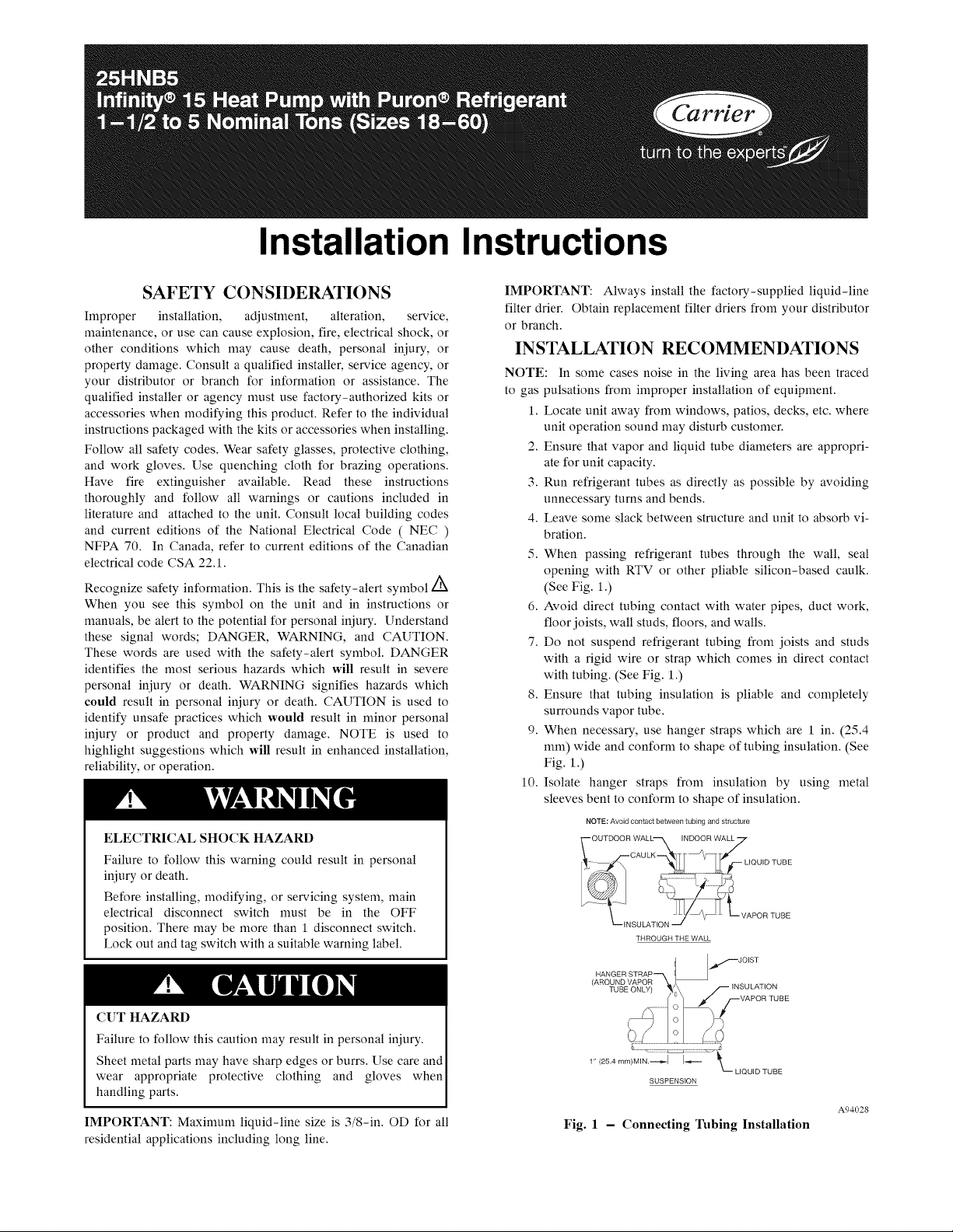
5. When passing refrigerant tubes through the wall, seal
opening with RTV or other pliable silicon-based caulk.
(See Fig. 1.)
6. Avoid direct tubing contact with water pipes, duct work,
floor joists, wall studs, floors, and walls.
7. Do not suspend refrigerant tubing from joists and studs
with a rigid wire or strap which comes in direct contact
with tubing. (See Fig. 1.)
8. Ensure that tubing insulation is pliable and completely
surrounds vapor tube.
9. When necessary, use hanger straps which are 1 in. (25.4
mm) wide and conform to shape of tubing insulation. (See
Fig. 1.)
10. Isolate hanger straps from insulation by using metal
sleeves bent to conform to shape of insulation.
NOTE: Avoid contact between tubing and structure
THROUGH THE WALL
CUT HAZARD I
Failure to follow this caution may result in personal injury. I
Sheet metal parts may have sharp edges or burrs. Use care and I
wear appropriate protective clothing and gloves when
handling parts.
IMPORTANT: Maximum liquid-line size is 3/8-in. OD for all
residential applications including long line.
SUSPENSION
A94028
Fig. 1 - Connecting Tubing Installation
When outdoor unit is connected to factory-approved indoor unit,
outdoor unit contains system refrigerant charge for operation with
AHRI rated indoor unit when connected by 15 ft/4.57 m. of
field-supplied or factory accessory tubing. For proper unit
operation, check refrigerant charge using charging information
located on control box cover and/or in the Check Charge section
of this instruction.
INSTALLATION
Check Equipment and Job Site
Unpack Unit
Move to final location. Remove carton taking care not to damage
unit.
Inspect Equipment
File claim with shipping company prior to installation if shipment
is damaged or incomplete. Locate unit rating plate on unit corner
panel. It contains information needed to properly install unit,
Check rating plate to be sure unit matches job specifications,
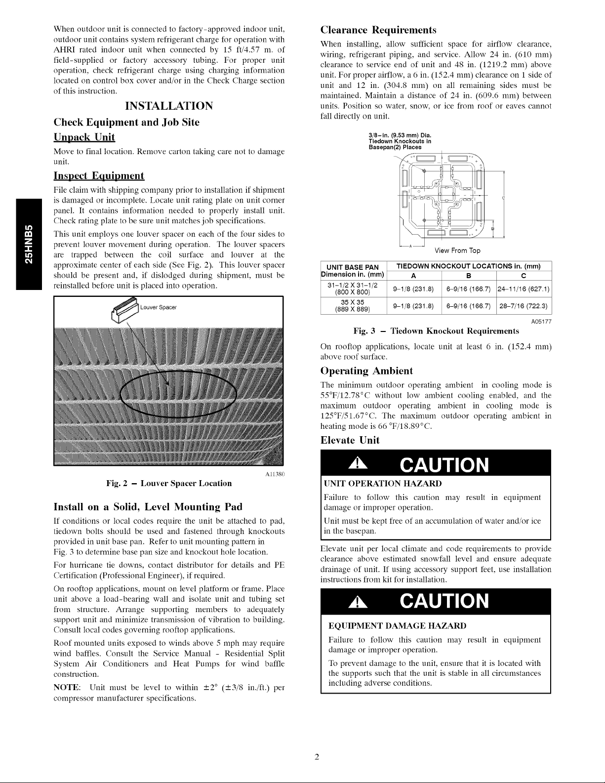
This unit employs one louver spacer on each of the four sides to
prevent louver movement during operation, The louver spacers
are trapped between the coil surface and louver at the
approximate center of each side (See Fig. 2). This louver spacer
should be present and, if dislodged during shipment, must be
reinstalled before unit is placed into operation,
Clearance Requirements
When installing, allow sufficient space for airflow clearance,
wiring, refrigerant piping, and service. Allow 24 in. (610 ram)
clearance to service end of unit and 48 in. (1219.2 ram) above
unit. For proper airflow, a 6 in. (152.4 ram) clearance on 1 side of
unit and 12 in. (304.8 ram) on all remaining sides must be
maintained. Maintain a distance of 24 in. (609.6 ram) between
units. Position so water, snow, or ice from roof or eaves cannot
fall directly on unit.
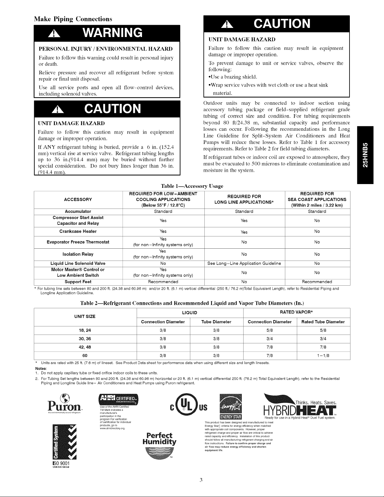
3/8-in. (9.53 mm) Dia.
Tiedown Knockouts in
Basepan(2) Places
1
View From Top
UNIT BASE PAN TIEDOWN KNOCKOUT LOCATIONS in. (mm)
Dimension in. (mm) A B C
31-1/2 X 31-1/2
(800 X 800) 9-1/8 (231.8) 6-9/16 (166.7) 24-11/16 (627.1)
35 X 35
(889 X 889) 9-1/8 (231.8) 6-9/16 (166.7) 28-7/16 (722.3)
A05177
Fig. 3 - Tiedown Knockout Requirements
On rooftop applications, locate unit at least 6 in. (152.4 ram)
above roof surface.
Operating Ambient
The minimum outdoor operating ambient in cooling mode is
55°F/12.78°C without low ambient cooling enabled, and the
maximum outdoor operating ambient in cooling mode is
125°F/51.67°C. The maximum outdoor operating ambient in
heating mode is 66 °F/18.89°C.
Elevate Unit
A11380
Fig. 2 - Louver Spacer Location
Install on a Solid, Level Mounting Pad
If conditions or local codes require the unit be attached to pad,
tiedown bolts should be used and fastened through knockouts
provided in unit base pan. Refer to unit mounting pattern in
Fig. 3 to determine base pan size and knockout hole location.
For hurricane tie downs, contact distributor for details and PE
Certification (Professional Engineer), if required.
On rooftop applications, mount on level platform or frame. Place
unit above a load-bearing wall and isolate unit and tubing set
from structure. Arrange supporting members to adequately
support unit and minimize transmission of vibration to building.
Consult local codes governing rooftop applications.
Roof mounted units exposed to winds above 5 mph may require
wind baffles. Consult the Service Manual - Residential Split
System Air Conditioners and Heat Pumps for wind baffle
construction.
NOTE: Unit nmst be level to within ---2° (---3/8 in./ft.) per
compressor manufacturer specifications.
UNIT OPERATION HAZARD
Failure to follow this caution may result in equipment
damage or improper operation.
Unit nmst be kept free of an accumulation of water and/or ice
in the basepan.
Elevate unit per local climate and code requirements to provide
clearance above estimated snowfall level and ensure adequate
drainage of unit. If using accessory support feet, use installation
instructions from kit for installation.
EQUIPMENT DAMAGE HAZARD
Failure to follow this caution may result in equipment
damage or improper operation,
To prevent damage to the unit, ensure that it is located with
the supports such that the unit is stable in all circumstances
including adverse conditions,
Make Piping Connections
UNIT DAMAGE HAZARD
PERSONAL INJURY / ENVIRONMENTAL HAZARD
Failure to follow this warning could result in personal injury
or death.
Relieve pressure and recover all refrigerant before system
repair or final unit disposal.
Use all service ports and open all flow-control devices,
including solenoid valves.
UNIT DAMAGE HAZARD
Failure to follow this caution may result in equipment
damage or improper operation.
If ANY refrigerant tubing is buried, provide a 6 in. (152.4
ram) vertical rise at service valve. Refrigerant tubing lengths
up to 36 in.(914.4 ram) may be buried without further
special consideration. Do not bury lines longer than 36 in.
(914.4 ram).
Table 1--Accessom Usage
REQUIRED FOR LOW-AMBIENT REQUIREDFOR
ACCESSORY COOLING APPLICATIONS SEA COAST APPLICATIONS
(Below 55°F / 12.8°C) (Within2 miles/ 3.22 km)
Accumulator Standard Standard Standard
Compressor Start Assist Yes Yes No
Capacitor and Relay
Crankcase Heater Yes Yes No
Yes
Evaporator Freeze Thermostat (for non-Infinity systems only) No No
Yes
Isolation Relay (for non-Infinity systems only) No No
Liquid Line Solenoid Valve No See Long-Line Application Guideline No
Motor Master@Control or Yes
LowAmbient Switch (for non-Infinity systems only)
Support Feet Recommended No Recommended
For tubing line sets between 80 and 200 ft. (24.38 and 60.96 m) and/or 20 ft. (6.1 m) vertical differential (250 ft./76.2 m)Total Equivalent Length), refer to Residential Piping and
Longline Application Guideline.
Table 2--Refrigerant Connections and Recommended Liquid and Va
UNIT SIZE
18, 24
30, 36
42, 48
60
Units are rated with 25 ft. (7.6 m) of lineset. See Product Data sheet for performance data when using different size and length linesets,
Notes:
1, Do not apply capillary tube or fixed orifice indoor coils to these units.
2, For Tubing Set lengths between 80 and 200 ft, (24,38 and 60,96 m) horizontal or 20 ft. (6.1 m) vertical differential 250 ft. (76.2 m) Total Equivalent Length), refer to the Residential
Piping and Longline Guide line- Air Conditioners and Heat Pumps using Puron refrigerant.
Connection Diameter
3/8
3/8
3/8
3/8
LIQUID
Failure to follow this caution may result in equipment
damage or improper operation.
To prevent damage to unit or service valves, observe the
following:
• Use a brazing shield.
• Wrap service valves with wet cloth or use a heat sink
material.
Outdoor units may be connected to indoor section using
accessory tubing package or field-supplied refrigerant grade
tubing of correct size and condition. For tubing requirements
beyond 80 ft/24.38 m, substantial capacity and performance
losses can occur. Following the recommendations in the Long
Line Guideline for Split-System Air Conditioners and Heat
Pumps will reduce these losses. Refer to Table 1 for accessory
requirements. Refer to Table 2 for field tubing diameters.
If refrigerant tubes or indoor coil are exposed to atmosphere, they
must be evacuated to 500 microns to eliminate contamination and
moisture in the system.
REQUIRED FOR
LONG LINEAPPLICATIONS*
No No
,or 1hbe Diameters (In.)
RATEDVAPOR*
Tube Diameter
3/8
3/8
3/8
3/8
Connection Diameter
5/8
3/4
7/8
7/8
Rated Tube Diameter
5/8
3/4
7/8
1-1/8
Pu olrl
IS0 9001
Use of the AHRI Certified
TM Mark _ndicates a
manufacturer's
participation _nthe
program For ver ff_cat_on
of certNcat_on for _ndMdua[
products, go to
w_ ahddgectory org
Q _Thinks. Heats.Saves.
c us HYBRIDEAT
TNS product has b_n designed and manufactured to meet
Energy StarB cdteria for energy efficiency when matched
w_th appropriate co_[ components Ho_ve_ proper
Perfect .........................................................
Humidity .............................................................flow _nstruct_ons Failure to confirm proper charge and
rated capacity and efficiency Installation oftNs product
air flow may reduce energy efficiency and shorten
equipment life.
Ready for use in a Hybrid Heat ® Duel Fuel system
Outdoor Unit Connected to Factory Approved
Indoor Unit
These outdoor units are carefully evaluated and listed with
specific indoor coils for proper system performance.
Install Adapter Tube
1. Remove plastic retainer holding outdoor piston in liquid
service valve,
2. Check outdoor piston size with matching number listed on
unit rating plate.
3. Locate plastic bag taped to unit containing adapter tube,
4. Remove TeflonD seal from bag and install on open end of
liquid service valve, (See Fig. 4.)
5. Remove adapter tube from bag and connect threaded nut
to liquid service valve. Tighten nut finger-tight and then
with wrench an additional 1/2 turn (15 ft-lb). DO NOT
OVER TIGHTEN!
-- TEFLON ® SEAL
A05227
Fig. 5 - Liquid Line Filter Drier
Leak Testing
Leak test all joints; indoors, outdoors, and refrigerant tubing.
Evacuate Refrigerant Tubing and Indoor Coil
L SWEAT/FLARE
L PISTON
PISTON BODY
-- LIQUID SERVICE VALVE
Fig. 4 - Liquid Service Valve
ADAPTER
A05226
Refrigerant Tubing and Sweat Connections
Connect vapor tube to fitting on outdoor unit vapor service
valves (see Table 2). Connect liquid tubing to adapter tube on
liquid service valve, Use refrigerant grade tubing.
UNIT DAMAGE HAZARD
Failure to follow this caution may result in equipment
damage or improper operation,
Service valves nmst be wrapped in a heat-sinking
material such as a wet cloth while brazing.
UNIT DAMAGE HAZARD
Failure to follow this caution may result in equipment
damage or improper operation,
Installation of filter drier in liquid line is required,
Install Liquid Line Filter Drier Indoor
Refer to Fig. 5 and install filter drier as follows:
1. Braze 5 in. (127 ram) liquid tube to the indoor coil.
2. Wrap filter drier with damp cloth.
3. Braze filter drier to 5 in. (127 ram) long liquid tube from
step 1.
4. Connect and braze liquid refrigerant tube to the filter drier.
UNIT DAMAGE HAZARD
Failure to follow this caution may result in equipment
damage or improper operation,
Never use the system compressor as a vacuum pump,
Refrigerant tubes and indoor coil should be evacuated using the
recommended deep vacuum method of 500 microns. An alternate
triple evacuation method may also be used, See Service Manual
for Triple Evacuation Method,
IMPORTANT: Always break a vacuum with dry nitrogen,
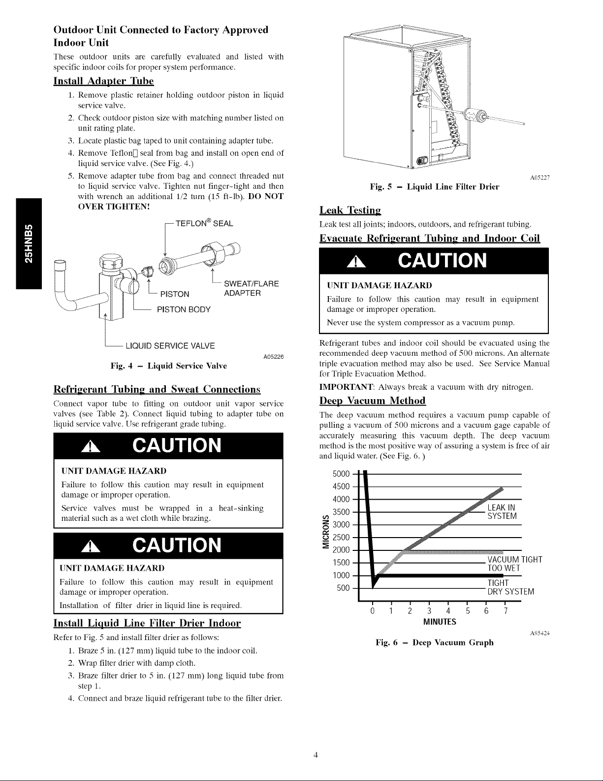
Deep Vacuum Method
The deep vacuum method requires a vacuum pump capable of
pulling a vacuum of 500 microns and a vacuum gage capable of
accurately measuring this vacuum depth. The deep vacuum
method is the most positive way of assuring asystem is free of air
and liquid water. (See Fig. 6. )
5000
4500
4000
3500
3000
M 2500
2000
1500
1000
500
TOOWET
TIGHT
DRYSYSIEM
0 1 2 3 4 5 6
MINUTES
Fig. 6 - Deep Vacuum Graph
TIGHT
A95424
 Loading...