

Page 1
Installation Instructions
SAFETY CONSIDERATIONS
Screw liquid chillers are designed to provide safe and reliable service when operated within design specifications. Whenoperatingthisequipment, use good judgment
and follow safety precautions to avoid damage to equipment and property or injury to personnel.
Be sure you understand and follow the procedures and
safety precautions contained in the machine instructions as well as those listed in this guide.
DO NOT VENT refrigerant relief devices within a building. Outlet
from rupture disc or relief valve must be vented outdoors in accordance with the latest edition of ANSI/ASHRAE 15 (American
National Standards Institute/American Society of Heating,
Refrigeration, and Air Conditioning Engineers). The accumulation
of refrigerant in an enclosed space can displace oxygen and cause
asphyxiation.
PROVIDE adequate ventilation in accordance with ANSI/ASHRAE
15, especially for enclosed and low overhead spaces. Inhalation of
high concentrations of vapor is harmful and may cause heart irregularities, unconsciousness, or death. Intentional misuse can be
fatal. Vapor is heavier than air and reduces the amount of oxygen
available for breathing. Product causes eye and skin irritation. Decomposition products are hazardous.
DO NOT USE OXYGEN to purge lines or to pressurize a machine
for any purpose. Oxygen gas reacts violently with oil, grease, and
other common substances.
DO NOT USE air to leak test. Use only refrigerant or dry
nitrogen.
NEVER EXCEED specified test pressures. VERIFY the allowable
test pressure by checking the instruction literature and the
design pressures on the equipment nameplate.
DO NOT VALVE OFF any safety device.
BE SURE that all pressure relief devices are properly installed and
functioning before operating any machine.
DO NOT WELD OR FLAMECUT any refrigerant line or vessel
until all refrigerant (liquid and vapor) has been removed from chiller .
Traces of vapor should be displaced with dry air or nitrogen and
the work area should be well ventilated. Refrigerant in contact with
an open flame produces toxic gases.
DO NOT USE eyebolts or eyebolt holes to rig machine sections or
the entire assembly.
DO NOT work on high-voltage equipment unless you are a qualified electrician.
DO NOT WORK ON electrical components, including control
center,switches, starters, or oil heater until you are sureALLPOWER
IS OFF and no residual voltage can leak from capacitors or solidstate components.
LOCK OPEN AND T AGelectricalcircuits during servicing. IF WORK
IS INTERRUPTED, confirm that all circuits are deenergized before resuming work.
DO NOT syphon refrigerant.
AVOID SPILLING liquid refrigerant on skin or getting it into the
eyes. USE SAFETY GOGGLES. Wash any spills from the skin
with soap and water. If liquid refrigerant enters the eyes, IMMEDIATELY FLUSH EYES with water and consult a physician.
23XL
50/60 Hz
Hermetic Screw Liquid Chillers
With HCFC-22 and HFC-134a
NEVER APPLY an open flame or live steam to a refrigerant
cylinder. Dangerous over pressure can result. When it is necessary
to heat refrigerant, use only warm (110 F [43 C]) water.
DO NOT REUSE disposable (nonreturnable) cylinders or
attempt to refill them. It is DANGEROUS AND ILLEGAL. When
cylinder is emptied, evacuate remaining gas pressure, loosen
the collar, and unscrew and discard the valve stem. DO NOT
INCINERATE.
CHECK THE REFRIGERANT TYPE before adding refrigerant to
the machine. The introduction of the wrong refrigerant can cause
machine damage or malfunction.
Operation of this equipment with refrigerants other than those
cited herein should comply with ANSI/ASHRAE-15 (latest
edition). Contact Carrier for further information on use of this
machine with other refrigerants.
DO NOTATTEMPTTO REMOVE fittings, covers, etc., while machine is under pressure or while machine is running. Be sure pressure is at 0 psig (0 kPa) before breaking any refrigerant connection.
CAREFULLY INSPECT all relief valves, rupture discs, and other
relief devices AT LEAST ONCE A YEAR. If machine operates in
a corrosive atmosphere, inspect the devices at more frequent
intervals.
DO NOT ATTEMPT TO REPAIR OR RECONDITION any
relief valve when corrosion or build-up of foreign material (rust,
dirt, scale, etc.) is found within the valve body or mechanism. Replace the valve.
DO NOT install relief devices in series or backwards.
USE CARE when working near or in line with a compressed spring.
Sudden release of the spring can cause it and objects in its path to
act as projectiles.
DO NOT STEP on refrigerant lines. Broken lines can whip about
and release refrigerant, causing personal injury.
DO NOT climb over a machine. Use platform, catwalk, or staging.
Follow safe practices when using ladders.
USE MECHANICAL EQUIPMENT (crane, hoist, etc.) to lift or
move inspection covers or other heavy components. Even if components are light, use mechanical equipment when there is a risk of
slipping or losing your balance.
BE AWARE that certain automatic start arrangements CAN
ENGAGE THE STARTER, TOWER FAN, OR PUMPS. Open the
disconnect ahead of the starter, tower fan and pumps. Shut off the
machine or pump before servicing equipment.
USE only repaired or replacement parts that meet the code requirements of the original equipment.
DO NOT VENTOR DRAIN waterboxes containing industrial brines,
liquid, gases, or semisolids without the permission of your process
control group.
DO NOT LOOSEN waterbox cover bolts until the waterbox has
been completely drained.
DOUBLE-CHECK that coupling nut wrenches, dial indicators, or
other items have been removed before rotating any shafts.
DO NOT LOOSEN a packing gland nut before checking that the
nut has a positive thread engagement.
PERIODICALLY INSPECT all valves, fittings, and piping for corrosion, rust, leaks, or damage.
PROVIDE A DRAIN connection in the vent line near each pressure relief device to prevent a build-up of condensate or rain
water.
Manufacturer reserves the right to discontinue, or change at any time, specifications or designs without notice and without incurring obligations.
Book 2
Tab 5e
PC 211 Catalog No. 532-303 Printed in U.S.A. Form 23XL-2SI Pg 1 9-94 Replaces: 23XL-1SI
Page 2
CONTENTS
Page
SAFETY CONSIDERATIONS ...................1
INTRODUCTION ..............................2
General ......................................2
Job Data ....................................2
Equipment Required .........................2
INSTALLATION .............................2-34
Receiving the Machine .......................2
• INSPECT SHIPMENT
• IDENTIFY MACHINE
• PROVIDE MACHINE PROTECTION
Rigging the Machine .........................4
• RIG MACHINE ASSEMBLY
• RIG MACHINE COMPONENTS
Install Machine Supports ....................16
• INSTALL STANDARD ISOLATION
• INSTALL OPTIONAL OR ACCESSORY
ISOLATION
• INSTALL SPRING ISOLATION
Connect Piping .............................18
• INSTALL WATER PIPING
TO HEAT EXCHANGERS
• INSTALL VENT PIPING
TO RELIEF DEVICES
Make Electrical Connections .................25
• CONNECT CONTROL INPUTS
• CONNECT CONTROL OUTPUTS
• CONNECT STARTER
• INSULATE MOTOR TERMINALS
AND LEAD WIRE ENDS
• CONNECT POWER WIRE TO OIL
HEATER CONTACTOR (Frame 1 and 2)
• CONNECT COMMUNICATION AND CONTROL
WIRING FROM STARTER TO POWER PANEL
• CARRIER COMFORT NETWORK
INTERFACE
Install Field Insulation .......................30
• FACTORY-INSTALLED INSULATION
INSTALLATION START-UP REQUEST
CHECKLIST ..........................CL-1, CL-2
INSTALLATION
Receiving the Machine
INSPECT SHIPMENT
Do not open any valves or break any connections. The
standard 23XL machine is shipped with a full refrigerant charge. Some machines may be shipped with a
nitrogen holding charge as an option.
1. Inspect for shipping damage while the machine is still on
shipping conveyance. If the machine appears to be damaged or has been torn loose from its anchorage, have it
examined by transportation inspectors before removal. Forward claim papers directly to the transportation company. The manufacturer is not responsible for any dam-
age incurred in transit.
2. Check all items against shipping list. Immediately notify
the nearest Carrier representative if any item is missing.
3. To prevent loss or damage, leave all parts in original packages until installation. All openings are closed with
covers or plugs to prevent dirt and debris from entering
during shipping. The 23XL is shipped with a full operating oil charge.
IDENTIFY MACHINE — The machine model number, serial number, and heat exchanger sizes are stamped on machine information plate (Fig. 1, 2, and 3). Check this information against shipping papers and job data.
INTRODUCTION
General—
and leak tested. Installation (not by Carrier) consists primarily of establishing water and electrical services to the machine. Rigging, installation, field wiring, and field piping are
the responsibility of the contractor and/or customer. Carrier
has no installation responsibilities for the equipment.
The 23XLmachine is factory assembled, wired,
Job Data
Necessary information consists of:
• job contract or specifications
• machine location prints
• rigging information
• piping prints and details
• field wiring drawings
• starter manufacturer’s installation details
• Carrier certified prints
Equipment Required
• mechanic’s tools (refrigeration)
• volt-ohmmeter and clamp-on ammeter
• leak detector (halide or electronic)
• absolute pressure manometer or wet-bulb vacuum
indicator
• portable vacuum pumps
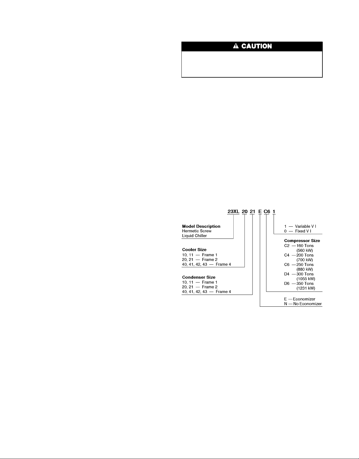
LEGEND
VI — Volumetric Index
Fig. 1 — Model Number Identification
PROVIDE MACHINE PROTECTION — Protect machine
and starter from construction dirt and moisture. Keep protective shipping covers in place until machine is ready for
installation.
If machine is exposed to freezing temperatures after water
circuits have been installed, open waterbox drains and remove all water from cooler and condenser.Leave drains open
until system is filled.
2
Page 3
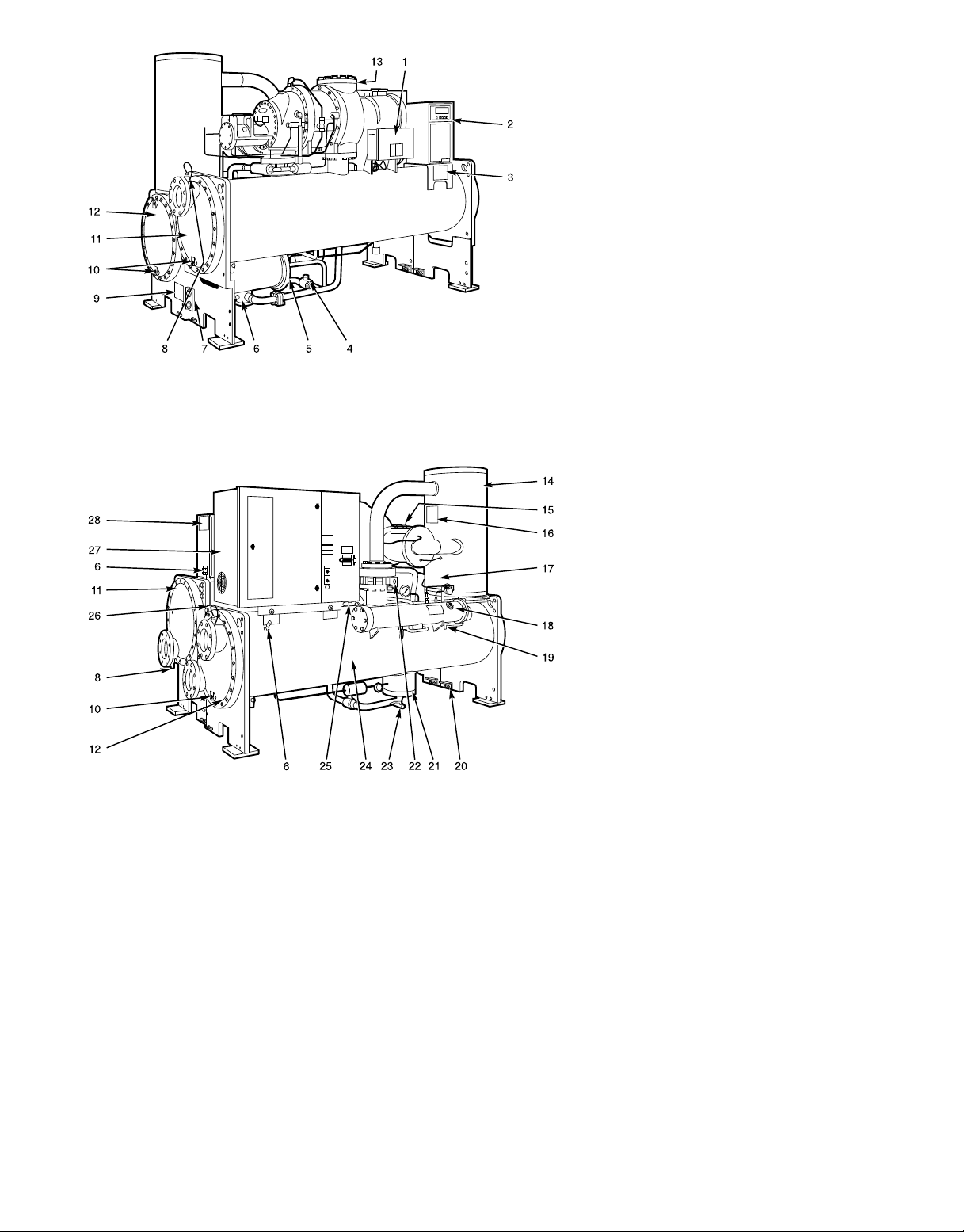
FRONT VIEW
REAR VIEW
1—Power Panel
2—Local Interface Display (LID) Control Center
3—ASME Nameplate, Cooler
4—Cooler Refrigerant Isolation Valve
5—ASME Nameplate, Economizer (Hidden)
6—Service Valve
7—Take-Apart Rabbet Fit Connector (Lower)
8—Cooler Temperature Sensor
9—ASME Nameplate, Condenser
10 — Typical Waterbox Drain Port
11 — Cooler Supply/Return End
Waterbox Cover
12 — Condenser Supply/Return End
Waterbox Cover
13 — Compressor Nameplate (Hidden)
14 — Oil Separator
15 — ASME Nameplate, Muffler (Hidden)
16 — ASME Nameplate, Oil Separator
17 — Cooler Relief Valves (Hidden)
18 — Oil Sump Filter Assembly
19 — Oil Charging Valve
20 — Vessel Separation Feet
21 — Float Chamber
22 — Condenser Isolation Valve (Option or
Accessory)
23 — Refrigerant Charging Valve
24 — Condenser
25 — Condenser Relief Valves (Hidden)
26 — Take-Apart Rabbet Fit Connector
(Upper)
27 — Unit Mounted Starter (Option)
28 — Machine Identification Nameplate
Fig.2—Typical 23XL Installation (Frame 1 and 2 Machines)
3
Page 4
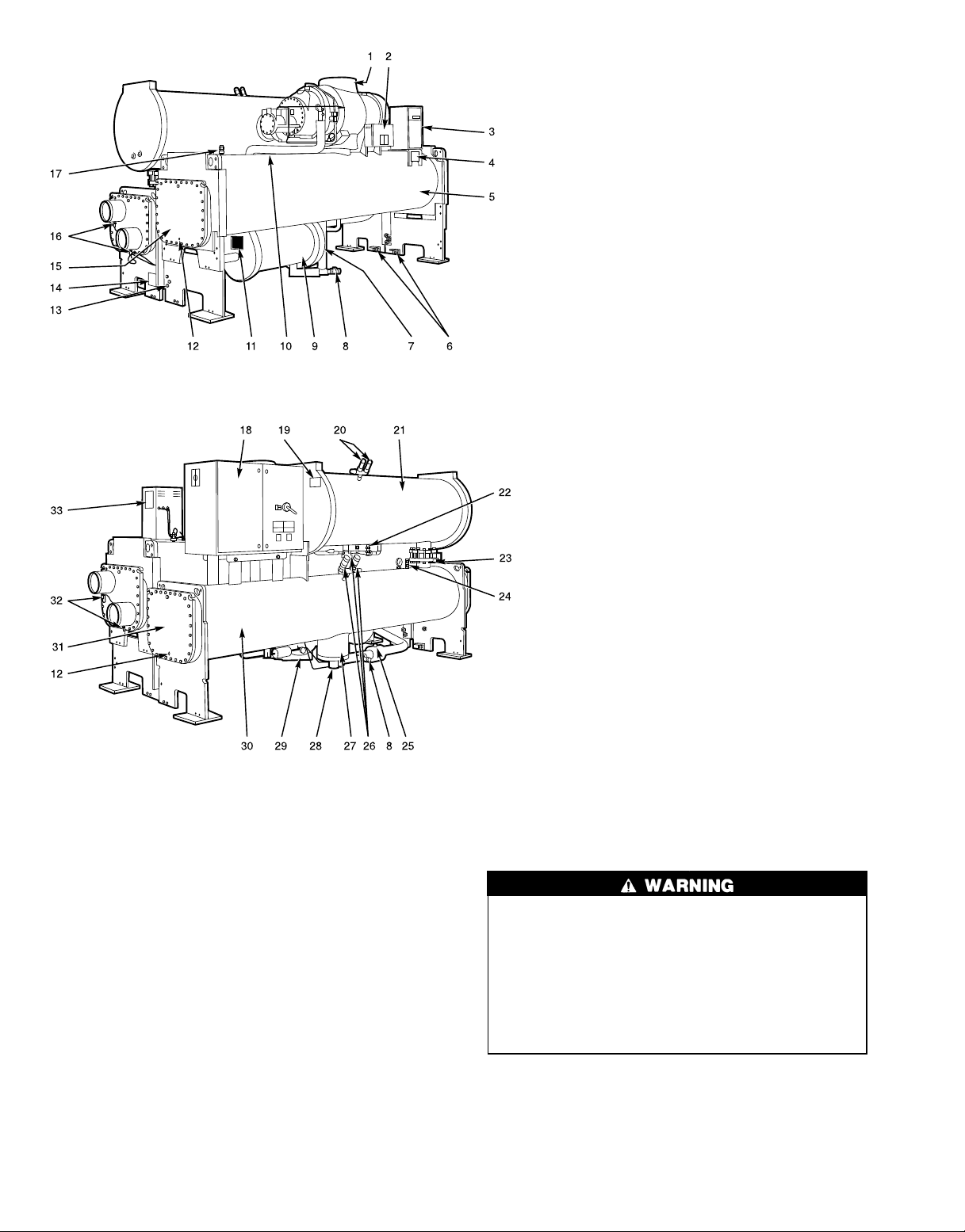
FRONT VIEW
REAR VIEW
1—Compressor Nameplate (Hidden)
2—Power Panel
3—Local Interface Display (LID) Control Center
4—ASME Nameplate, Cooler
5—Cooler
6—Vessel Separation Feet
7—Economizer Float Valve Access Cover
(Hidden)
8—Refrigerant Charging Valve
9—Economizer
10 — Oil Filter Assembly (Hidden)
11 — ASME Nameplate, Economizer
12 — Typical Waterbox Drain Port
13 — Take-Apart Rabbet Fit Connector
14 — ASME Nameplate, Condenser
15 — Cooler Supply/Return End Waterbox Cover
16 — Condenser Temperature Sensors
17 — Cooler Relief Valve
18 — Unit Mounted Starter (Option)
19 — ASME Nameplate, Oil Separator
20 — Oil Separator Relief Valves
21 — Oil Separator
22 — Oil Charging Valve
23 — Condenser Isolation Valve (Option or
Accessory)
24 — Service Valve
25 — Cooler Refrigerant Isolation Valve
26 — Condenser Relief Valves and Oil Filter
27 — Float Chamber
28 — Poppet Valve Assembly
29 — Motor Cooling Isolation Valve
30 — Condenser
31 — Condenser Supply/Return End
Waterbox Cover
32 — Cooler Temperature Sensors
33 — Machine Identification Nameplate
Fig.3—Typical 23XL Installation (Frame 4 Machine)
Rigging the Machine — The 23XL can be rigged as
an entire assembly. It also has flanged connections that
allow the compressor, cooler, condenser, and oil separator
sections to be separated to fulfill specific installation
requirements.
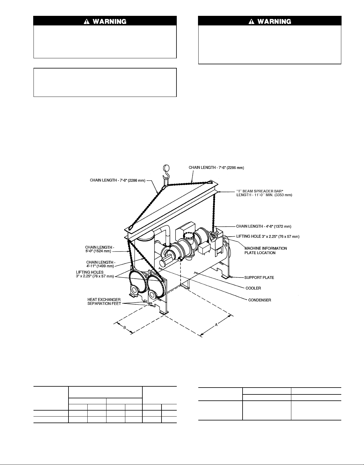
RIG MACHINE ASSEMBLY — See rigging instructions
in plastic envelope attached to machine. Also refer to rigging guide (Fig. 4 and 5), physical data in Fig. 6 and 7, and
Tables 1-6. Lift machine only from the 3 points indicated in
the rigging guide. Spreader bar must be used. Each lifting
cable or chain must be capable of supporting the entire weight
of the machine.
Lifting machine from points other than those specified
may result in serious damage and personal injury. Rigging equipment and procedure must be adequate for
machine weight. See Tables 1-6 for machine weights.
NOTE: These weights are broken down into component
sections for use when installing the unit in sections. For
complete machine weight, add all section components
together. Total machine weight (Table 6) is also stenciled on the cooler and condenser sections.
4
Page 5
→
The compressor is heavy. To avoid bodily injury, lift
the compressor only by using cables or slings. Do not
lift thecompressor using threaded eyebolts. Metric threaded
eyebolts are provided only for lifting individual compressor castings.
Do not attempt to cut refrigeration lines or disconnect
flanges or fittings while machine is under pressure. Cutting lines or disconnecting flanges or fittings can result
in personal injury or damage to the unit. Be sure both
refrigerant and oil charge are removed from the machine before separating the components.
IMPORTANT: Only a qualified service technician
should disassemble and reassemble the machine. After
reassembly, the machine must be dehydrated and leak
tested.
RIG MACHINE COMPONENTS — Refer to instructions
below, Fig. 8-12, and Carrier certified prints for machine
disassembly.
NOTE: If the cooler and condenser vessels must be separated, the heat exchanger separation feet must be unbolted,
rotated, and rebolted in order to keep each heat exchanger
level. See Fig. 4, 5, and 8-12.
NOTE: Sensor wiring must be disconnected. Label each wire
before removal (see Carrier certified prints). Remove all transducer and thermistor wires at the sensor. Clip all wire ties
necessary to remove the wires from the heat exchangers. Remove the control wiring and oil heater wiring
(Frame 1 and 2 machines) at the power panel and the main
motor leads at the starter lugs before disconnecting the starter
from the machine.
*Carrier recommends that ‘‘I’’ Beam Spreader Bars be field supplied and installed.
NOTES:
1. Each chain must be capable of supporting the entire weight of the machine. Maximum weight of machine is 13,200 lbs (5940 Kg).
2. Chain lengths shown are typical for 15 ft (4572 mm) lifting height. Some minor
adjustment may be required.
HEAT
EXCHANGER
SIZE
10 or 11 3- 8 1117 1-11 572 11,810 5357
20 or 21 3-10 1161 2- 0 600 13,200 5940
CENTER OF GRAVITY —
APPROXIMATE DIMENSIONS
A (Length) B (Width)
ft-in. mm ft-in. mm lb Kg
MAXIMUM
WEIGHT
Fig. 4 — Machine Rigging Guide (Frame 1 and 2 Machines)
5 796
Suggested ‘‘I’’ Beam Spreader Bar*
OPTIONS
1 S12 x 31.8 S30 x 464
2 S10 x 35 S25.4 x 511
3 W12 x 22 W30 x 321
4 W10 x 25 W25.4 x 365
ENGLISH SI
in. x lb/ft cm x N/m
Page 6
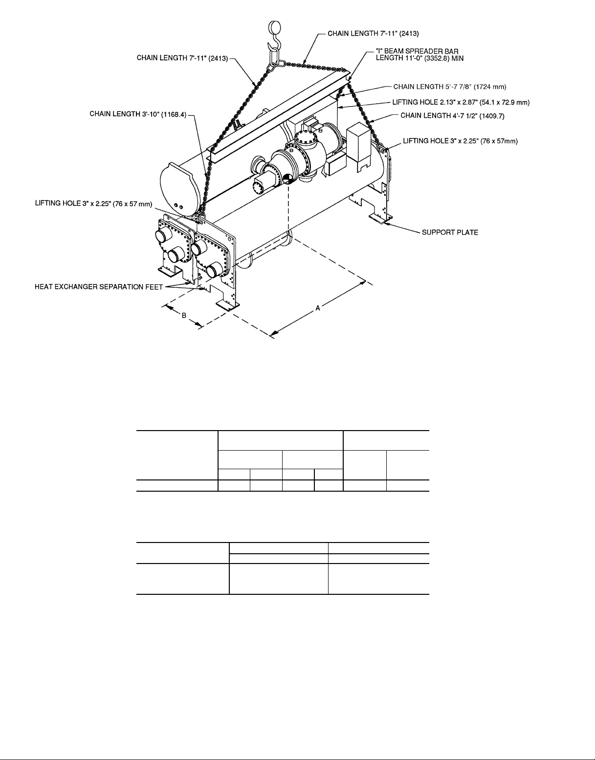
NOTES:
1. Each chain must be capable of supporting the entire weight of the machine. Maximum weight of machine is 22,300 lbs (10,116 Kg).
2. Chain lengths shown are typical for 15 ft (4572 mm) lifting height. Some minor adjustment may be required.
3. [ ] indicates millimeters.
CENTER OF GRAVITY —
HEAT EXCHANGER
SIZE
40, 41, 42, or 43 6-4 1930 2-8 813 22,300 10,116
*Includes marine waterboxes and refrigerant charge.
APPROXIMATE DIMENSIONS
A
(Length)
ft-in. mm ft-in. mm
B
(Width)
MAXIMUM WEIGHT*
lb kg
Suggested ‘‘I’’ Beam Spreader Bar†
OPTIONS
1 S12 x 31.8 S30 x 464
2 S10 x 35 S25.4 x 511
3 W12 x 22 W30 x 321
4 W10 x 25 W25.4 x 365
†Carrier recommends that ‘‘I’’ beam spreader bars be field supplied and installed.
ENGLISH SI
in. x lb/ft cm x N/m
Fig. 5 — Machine Rigging Guide
(Frame 4 Machines)
6
Page 7
23-22
HEAT EXCHANGER
SIZE
10 or 11
20 or 21 4-11 1499 6-11
1 Pass 2 and 3 Pass*
ft-in. mm ft-in. mm ft-in. mm ft-in. mm 1-Pass 2 and 3-Pass
9-5 2870 9-6
A (LENGTH)
1
⁄
2
2908
OVERALL
B (WIDTH)
1
4- 9
⁄
4
*2 and 3-pass length applies if either (or both) cooler or condenser isa2or3-pass design.
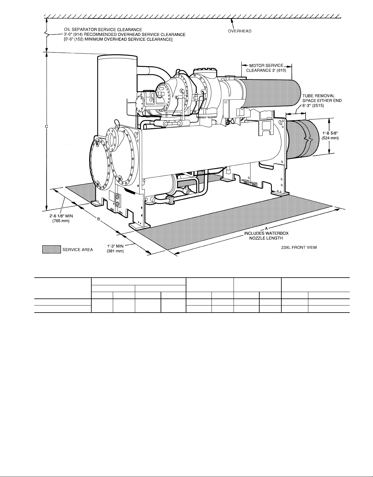
NOTES:
1. Service access should be provided per ANSI/ASHRAE 15 (American National Standards
Institute/American Society of Heating Refrigeration and Air Conditioning Engineers), Latest Edition. NFPA (National Fire Protection Association) 70 and local safety codes.
2. Allow at least 6 in. (152 mm) overhead clearance for service rigging.
3. Certified drawings available upon request.
→
Fig. 6 — 23XL Dimensions (Frame 1 and 2 Machines)
OVERALL
C (HEIGHT)
1454 6- 95⁄
NOZZLE PIPE SIZE
8
2073 6 6
3
⁄
8
2118 8 6
(in.)
7 796
Page 8
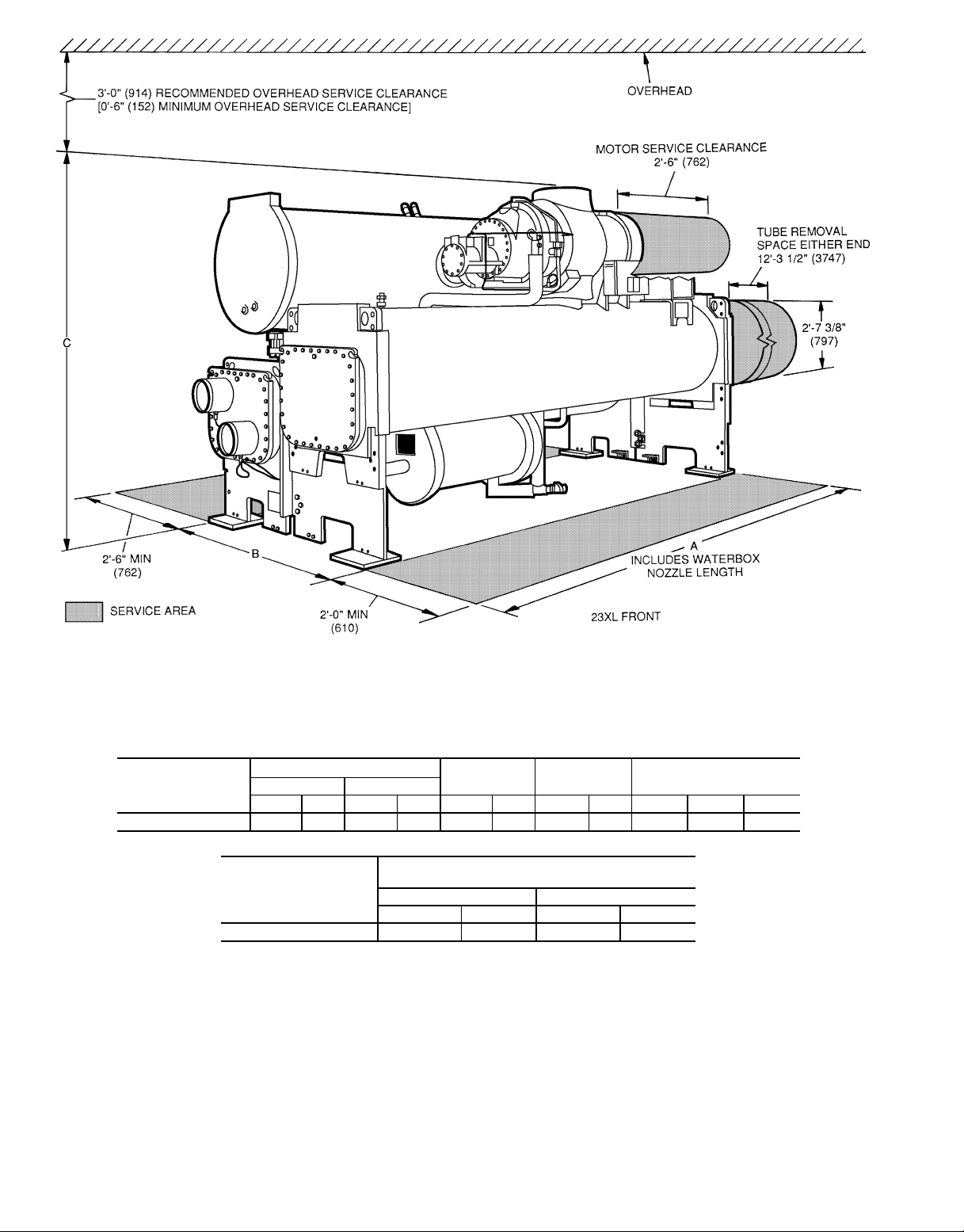
NOTES:
1. For flanged waterbox nozzles, refer to the certified drawings for length addition measurements.
2. Service access should be provided based onAmerican Society of Heating, Refrigeration, and Air Conditioning Engineers
(ASHRAE) 15, latest edition, National Fire Protection Association (NFPA) 70, and local safety codes.
3. A minimum 6 in. (152 mm) overhead clearance for service rigging is recommended.
4. Certified drawings are available upon request.
5. [ ] indicates millimeters.
HEAT EXCHANGER
(Cooler and
Condenser Size)
40-43 13-7
*Assumes both cooler and condenser nozzles on same end of chiller.
†1 or 3 pass length applies if either (or both) cooler or condenser isa1or3pass
design.
A (LENGTH)
2 Pass* 1 or 3 Pass†
OVERALL
B (WIDTH)
OVERALL
C (HEIGHT)
NOZZLE PIPE SIZE (in.)
(Nominal Pipe Size)
ft-in. mm ft-in. mm ft-in. mm ft-in. mm 1-Pass 2-Pass 3-Pass
3
⁄44159 14-31⁄44350 5-107⁄81800 7-611⁄162303 10 8 6
HEAT EXCHANGER
(Cooler and
Condenser Size)
40-43 14-9
Marine Waterbox — Not Shown)
2 Pass* 1 or 3 Pass†
ft-in. mm ft.-in. mm
5
⁄
8
A (Length With
4512 16-51⁄
2
5017
Fig. 7 — 23XL Dimensions (Frame 4 Machines)
9
Page 9
Table 1 — 23XL Compressor Weights
Table 2 — 23XL Component Weights
23XL
UNIT
Frame 1
Frame 2 C6 2400 1088
Frame 4
COMPRESSOR SIZE
(Tons)
C2 2270 1029
C4 2300 1043
D4 3300 1497
D6 3400 1542
ASSEMBLY
(Less Motor)
lb kg
COMPONENT
Oil Separator 1180 535 2880* 1306*
Economizer† 296 134 560 254
Muffler 170 77 * *
Discharge Piping:
Pipe 44 20 — —
Isolation Valve† 30 14 30 14
Adaptor Flange 76 34 76 34
Power Panel 20 9 20 9
Starter† 500 227 500 227
Control Center 31 14 31 14
*The Frame 4 muffler is included in the oil separator weight.
†Optional.
FRAME 1 AND 2 FRAME 4
lb kg lb kg
Table 3 — 23XL Motor Weights*
COMPRESSOR
Size VI Type lb kg lb kg lb kg
C2 0 125 230 104 58 26 310 141
C4 0 155 249 113 63 29 310 141
C4 1
C6 0or1
D4 0 or 1 280 460 208 110 49 370 167
D6 0 or 1 280 460 208 110 49 370 167
LEGEND
VI — Volumetric Index
*C2-C6 listed weights are for low-voltage motors (200-600 v). D4-D6 listed weights are for
low-voltage motors (320-600 v).
MAX IkW
195 276 125 69 31 310 141
STATOR ROTOR MOTOR CASING AND COVER
→
Dry Wt (lb)* Machine Charge
SIZE
10 2480 2890 650 ** 600 ** 34 39.2
11 2650 3020 650 ** 600 ** 40 44.4
20 2845 3250 750 ** 700 ** 45 49.2
21 3000 3445 750 ** 700 ** 49 56.4
40 5030 4690 1000 850 900 800 49.2 51.6
41 5180 4835 1100 900 1000 850 54 57
42 5345 5005 1200 950 1100 900 60 63
43 5525 5185 1300 1000 1200 950 66 70
SIZE
10 1125 1310 295 ** 272 ** 130 150
11 1202 1370 295 ** 272 ** 152 168
20 1291 1474 340 ** 318 ** 170 186
21 1361 1563 340 ** 318 ** 186 214
40 2282 2127 454 385 408 363 186 195
41 2350 2193 499 408 454 385 204 216
42 2424 2270 544 431 499 408 227 239
43 2506 2352 590 454 544 431 250 264
LEGEND
NIH — Nozzle-In-Head
*Weight based on: .035 in. wall copper Turbo-B2 tubes in cooler, Turbo chill in condenser.
†Weight of optional economizer is not included and must be added to cooler weight.
**Not available.
NOTE: Standard shipment is with refrigerant charged, so be sure to add refrigerant charge to dry weight.
Cooler
Only†
Dry Wt (kg)* Machine Charge
Cooler
Only†
2-pass, 150 psi NIH waterbox arrangements (sizes 10, 11, 20, 21)
3-pass, 300 psi NIH waterbox arrangements (sizes 40, 41, 42, 43)
Cond
Only
Cond
Only
Table 4 — 23XL Heat Exchanger Weights
ENGLISH
Refrigerant (lb) Water (gal)
Economizer No Economizer
HCFC-22 HFC-134a HCFC-22 HFC-134a
SI
Refrigerant (kg) Water (L)
Economizer No Economizer
HCFC-22 HFC-134a HCFC-22 HFC-134a
Cooler Cond
Cooler Cond
9 796
Page 10
Table 5A — 23XL Waterbox Cover Weights (Frame 1 and 2 Machines)*
HEAT EXCHANGER
NIH, 1 Pass
Cooler or
Condenser
LEGEND
NIH — Nozzle-In-Head
*These weights are given for reference only.Theyhave been includedin heat exchangerweights
shown in Table 4.
NOTE: Add 30 lb (14 Kg) for bolts.
NIH, 2 Pass (Plain) 100 46 148 67
NIH, 2 Pass (With Pipe Nozzles) 185 84 200 91
NIH, 3 Pass
WATERBOX
DESCRIPTION
PSI
(kPa)
150
(1034)
150
(1034)
Table 5B — 23XL Waterbox Cover Weight (Frame 4 Machines)*
ENGLISH (lb) SI (kg)
HEAT
EXCHANGER
COOLER
CONDENSER
LEGEND
CS — Contact Syracuse
MWB — Marine Waterbox
NIH — Nozzle-In-Head
*These weights are given for reference only. The 150 psig (1034 kPa) standard waterbox cover
weights have been included in the heat exchanger weights shown in Table 4.
WATERBOX
DESCRIPTION
NIH, 1 Pass Cover 284 414 324 491 129 188 147 223
NIH, 2 Pass Cover 285 411 341 523 129 187 155 237
NIH, 3 Pass Cover 292 433 309 469 133 197 140 213
NIH, Plain End Cover 243 292 243 292 110 133 110 133
MWB Cover CS 621 CS 621 CS 282 CS 282
Plain End Cover CS 482 CS 482 CS 219 CS 219
NIH, 1 Pass Cover 306 446 346 523 139 202 157 237
NIH, 2 Pass Cover 288 435 344 547 131 197 156 248
NIH, 3 Pass Cover 319 466 336 502 145 212 153 228
NIH, Plain End Cover 226 271 226 271 103 123 103 123
MWB Cover CS 474 CS 474 CS 215 CS 215
Plain End Cover CS 359 CS 359 CS 163 CS 163
Frame 4,
Std Nozzles
150 psig 300 psig 150 psig 300 psig 1034 kPa 2068 kPa 1034 kPa 2068 kPa
Frame 4,
Flanged
FRAME 1 FRAME 2
lbs kg lbs kg
118 54 128 58
166 76 180 82
Frame 4,
Std Nozzles
Frame 4,
Flanged
→
COOLER SIZE CONDENSER SIZE
10 or 11 10 or 11
20 or 21 20 or 21
40, 41, 42, or 43 40, 41, 42, or 43
LEGEND
VI — Volumetric Index
*Total rigging weight includes HCFC-22 and water.
NOTE: Starter weight is included in total weights. Subtract 500 lbs (227 kg) if a starter is not used.
Table 6 — 23XL Machine Rigging Weights
ECONOMIZER
INDICATOR
YES
NO 11,110 5,039
YES
NO 12,260 5,561
YES
NO 19,520 8,855
COMPRESSOR
SIZE
C2 or C4 0 or 1
C6 0or1
D4 or D6 0 or 1
796 10
VI TYPE
TOTAL RIGGING WEIGHT*
lbs kg
11,410 5,175
12,560 5,697
20,020 9,081
Page 11
NOTE: Before proceeding with disassembly, make sure the
machine is at atmospheric pressure.
NOTE: The screw compressor uses all metric dimensions
→
and metric fasteners. The heat exchangers and oil separator
use American standard dimensions and English fasteners.
Metric wrenches are required to remove the compressor.
To Separate Cooler and Condenser (Frame 1 and 2
Machines)
1. Turn vessel separation feet to the lowered position
(Fig. 8).
2. Disconnect and/or cut the following lines:
a. cooler liquid feed (Fig. 8).
b. condenser refrigerant vapor to oil reclaim ejector
(Fig. 9).
c. motor cooling supply from condenser (Fig. 9).
d. optional hot gas bypass and associated solenoid valve
wiring (not shown).
3. Separate compressor from oil supply system by disconnecting the following:
a. discharge flange from compressor and remove check
valve (Fig. 8).
b. oil supply line to compressor and associated solenoid
valve wiring (Fig. 8).
c. oil scavenging/sump vent to compressor (Fig. 8
and 9).
4. Cover all openings.
5. Be sure all wiring is properly marked. Detach all transducers, switches, and sensor wires. Remove all wire ties
required to remove wires from the cooler to the condenser. Do not cut the wires.
6. Disconnect the rabbet fit connectors on the tube sheets
(Fig. 9).
7. Rig vessels apart.
To Separate Compressor from Cooler (Frame 1 and 2
Machines)
→
The compressor is heavy. To avoid bodily injury, lift
the compressor only by using cables or slings. Do not
lift the compressor using threaded eyebolts. The metric
threaded eyebolts are provided only for lifting individual compressor castings.
1. Unbolt the suction flange (Fig. 8).
2. Disconnect the following lines:
a. oil reclaim to compressor (Fig. 9).
b. motor cooling to motor (Fig. 9).
c. motor cooling drain (Fig. 9).
d. optional economizer gas line to compressor rotors
(Fig. 9).
3. Separate compressor from oil supply system by disconnecting the following:
a. discharge flange from compressor and remove check
valve (Fig. 8).
b. oil supply line to compressor and associated solenoid
valve wiring (Fig. 8 and 9).
c. oil scavenging/sump vent to compressor (Fig. 8
and 9).
4. Cover all openings.
5. Be sure the following electrical connections are
disconnected:
a. motor power cables from optional unit-mounted starter
lugs (not shown).
b. motor winding temperature sensor (Fig. 9).
c. slide valve increase and decrease capacity control so-
lenoid valves (Fig. 9).
d. optional variable VI solenoid valves (Fig. 9).
e. discharge (condenser) pressure transducer (Fig. 8).
6. Unbolt motor support foot (Fig. 8).
7. Rig compressor.
To Separate Oil Separator from Condenser (Frame 1 and 2
Machines)
1. Separate the compressor and oil separator by disconnecting the following:
a. discharge flange from compressor and remove check
valve (Fig. 8).
b. oil feed from separator to sump (Fig.9).
c. oil scavenging/sump vent to compressor (Fig. 8
and 9).
d. oil sump relief to separator (Fig. 8).
2. Unbolt the discharge adaptor flange from the condenser
(Fig. 9).
3. Cover all openings.
4. Be sure the following electrical connections are
disconnected:
a. high discharge pressure cutout switch (Fig. 8).
5. Unbolt the four securing bolts from the bottom of the oil
separator (Fig. 8 and 9).
6. Rig oil separator.
NOTE: Before proceeding with disassembly, make sure the
machine is at atmospheric pressure.
To Separate Cooler and Condenser (Frame 4 Machines)
→
The compressor is heavy. To avoid bodily injury, lift
the compressor only by using cables or slings. Do not
lift the compressor using threaded eyebolts. The metric
threaded eyebolts are provided only for lifting individual compressor castings.
11 796
Page 12

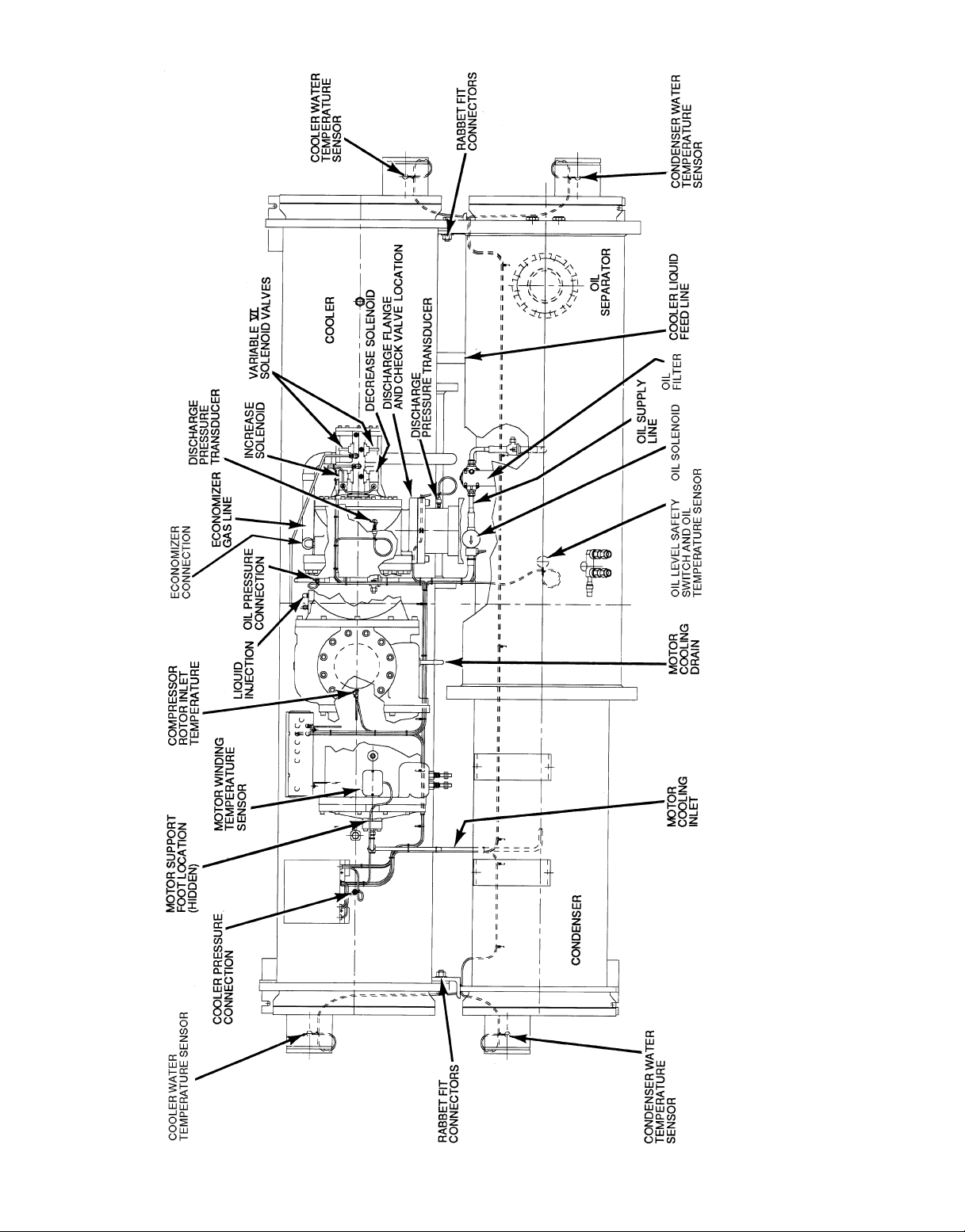
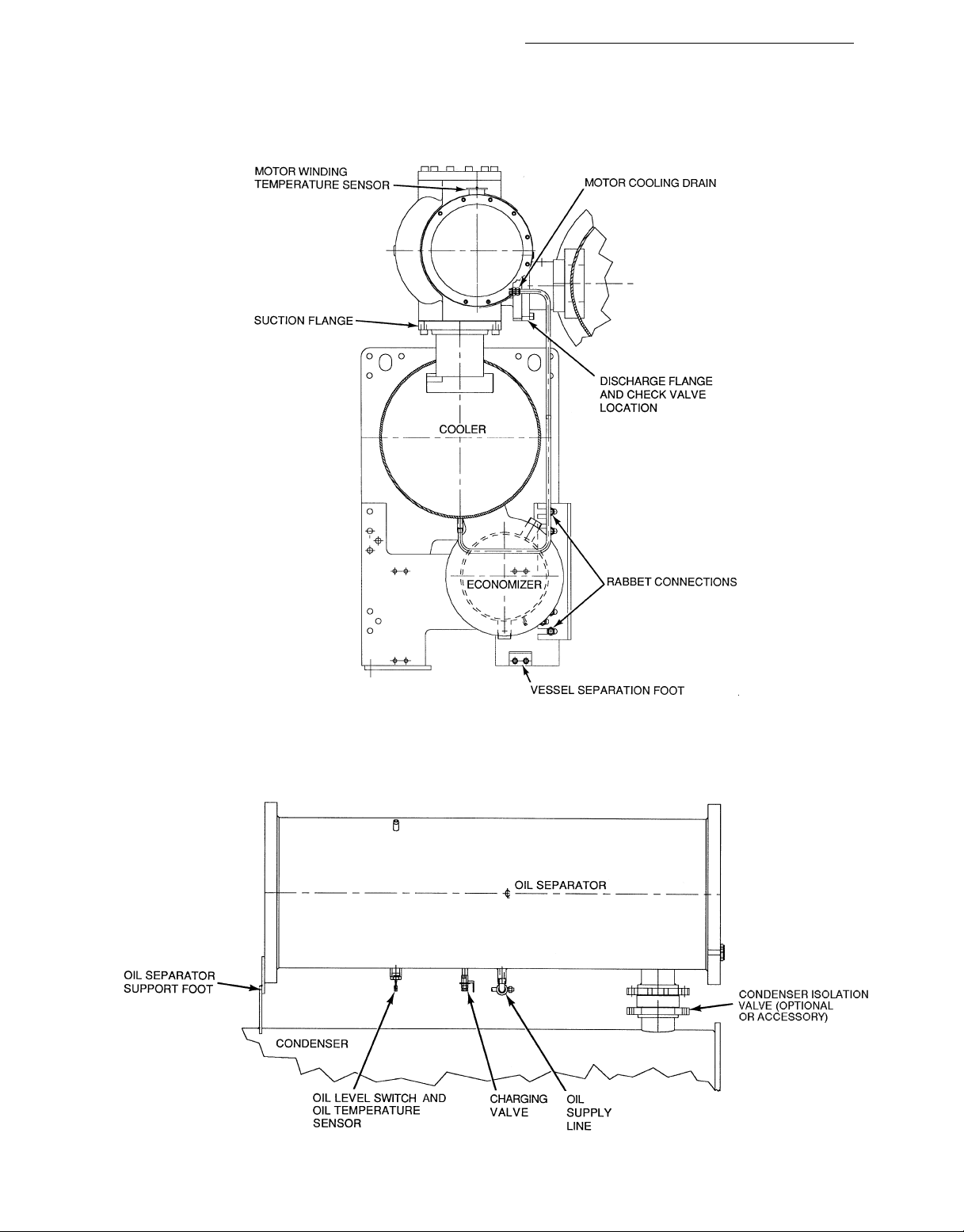
Fig. 8 — 23XL Drive End View (Frame 1 and 2 Machines)
Refer to Fig. 10 unless otherwise specified.
1. Turn all 4 vessel separation feet to the lowered position
(Fig. 11).
2. Disconnect and/or cut the following lines, as required:
a. cooler liquid feed.
b. motor cooling supply from condenser.
c. liquid injection to compressor.
d. bubble line to float chamber (not shown).
e. optional hot gas bypass and associated solenoid valve
wiring (not shown).
f. motor power cables from optional unit mounted starter
lugs (not shown).
3. Separate compressor by disconnecting the following:
a. discharge flange from compressor (remove the check
valve).
b. oil supply line to compressor and associated solenoid
valve wiring.
4. Cover all openings.
5. Be sure all wiring is properly marked. Detach all transducers, switches, and sensor wires. Remove all wire ties
required to remove wires from the cooler to the condenser. Do not cut the wires.
6. Disconnect the rabbet fit connectors on the tube sheets.
7. Rig vessels apart.
To Separate Compressor from Cooler (Frame 4 Machines)
1. Unbolt the suction flange (Fig. 11).
2. Disconnect the following lines:
a. motor cooling to motor (Fig. 10).
b. motor cooling drain (Fig. 11).
c. optional economizer gas line to compressor rotors
(Fig. 10).
d. liquid injection to compressor (Fig. 10).
3. Separate compressor from oil supply system by disconnecting the following:
a. discharge flange from compressor and remove check
valve (Fig. 10).
b. oil supply line to compressor and associated solenoid
valve wiring (Fig. 10).
4. Cover all openings.
5. Be sure the following electrical connections are
disconnected:
a. motor power cables from optional unit-mounted starter
lugs (not shown).
b. motor winding temperature sensor (Fig. 10).
c. slide valve increase and decrease capacity control so-
lenoid valves (Fig. 10).
d. optional variable VI solenoid valves (Fig. 10).
e. discharge (condenser) pressure transducer (Fig. 10).
6. Unbolt motor support foot (Fig. 10).
7. Rig compressor.
To Separate Oil Separator from Condenser (Frame 4
Machines)
Refer to Fig. 12 unless otherwise specified.
1. Separate the compressor and oil separator by disconnecting the following:
a. discharge flange from compressor (secure the check
valve). See Fig. 11.
b. oil supply line from separator to compressor.
12
Page 13

13
Fig. 9 — 23XL Top View (Frame 1 and 2 Machines)
Page 14
14
Fig. 10 — 23XL Top View (Frame 4 Machines)
Page 15
2. Cover all openings.
3. Be sure the switches, sensor, and transducers are
disconnected.
4. Cut oil separator from its support foot.
5. Rig oil separator.
Additional Notes For Frame 1, 2, and 4 Machines:
1. Use silicon grease on new O-rings when refitting.
2. Use gasket sealant on new gaskets when refitting.
3. Cooler and condenser may be vertically rigged. Rigging
should be fixed to 4 corners of the cooler and condenser
tube sheet.
→
Fig. 11 — Motor Cooling Drain Section
(Frame 4 Machines)
Fig. 12 — Oil Separator Section
(Frame 4 Machines)
15 796
Page 16
Install Machine Supports
INSTALLSTANDARDISOLATION— Figures 13-18 show
the position of support plates and shear flex pads that form
the standard machine support system.
INSTALL OPTIONAL OR ACCESSORY ISOLATION (if
required) — Uneven floors or other considerations may
dictate the use of soleplates and leveling pads. Refer to
Fig. 13-18.
Level machine by using jacking screws in isolation sole-
plates. Use a level at least 24 in. (600 mm) long.
DIMENSION
A 4-51⁄
B 4-4
C 1-0
NOTES:
1. Dimensions in ( ) are in millimeters.
2. Use grout and package components to establish the level base line.
3. If chiller is set on concrete pad, electrical contractor is to locate conduit stub-ups outside of pad.
4. See Fig. 15 and 16 for additional information.
HEAT EXCHANGER SIZE
10 or 11 20 or 21
ft-in. mm ft-in. mm
4
1
⁄
2
3
⁄
8
1353 4-71⁄
1334 4-61⁄
314 1-13⁄
4
1403
2
1384
8
340
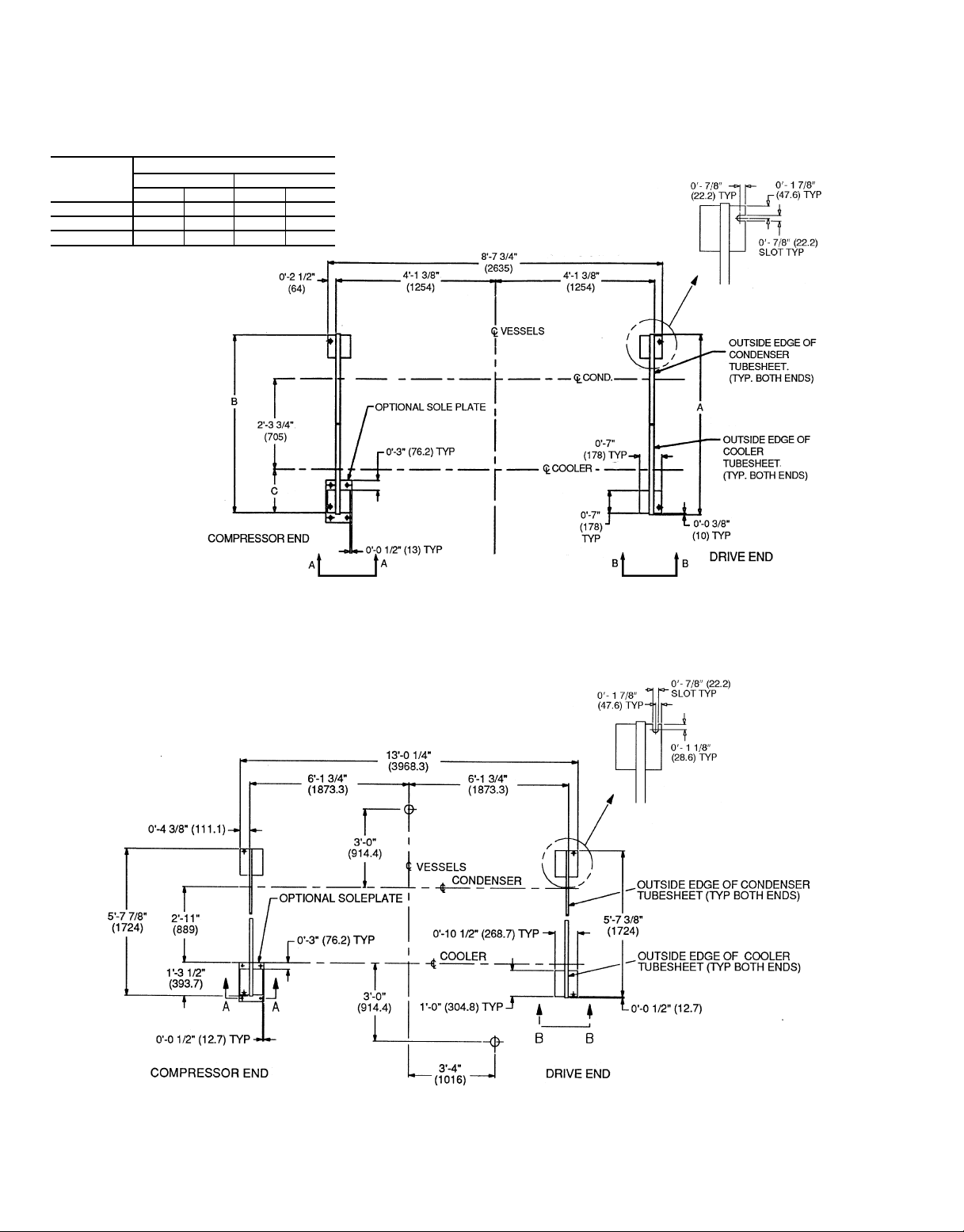
Fig. 13 — 23XL Machine Footprint (Frame 1 and 2 Machines)
Approximate
location shown.
NOTES:
1. Dimensions in ( ) are in millimeters.
2. Use grout and package components to establish the level base line.
3. If chiller is set on concrete pad, electrical contractor is to locate conduit stub-ups outside of pad.
4. See Fig. 15 and 16 for additional information.
Fig. 14 — 23XL Machine Footprint (Frame 4 Machine)
16
Approximate
location shown.
Page 17

VIEW B-B
NOTES:
1. Dimensions in ( ) are in millimeters.
2. Isolation package includes 4 shear flex pads.
Fig. 15 — Standard Isolation
HRS — Hot Rolled Steel
NOTES:
1. Dimensions in ( ) are in millimeters.
2. Accessory (Carrier supplied, field installed) soleplate package in-
cludes 4 soleplates, 16 jacking screws and leveling pads. Requires accessory spring vibration isolation package.
3. Jacking screws to be removed after grout has set.
4. Thickness of grout will vary, depending on the amount necessary
to level chiller. Use only pre-mixed non-shrinking grout, Celcote
HT-648or Master Builders 636, 08-1
Fig. 16 — Accessory Isolation
1
⁄29 (38.1) to 08-21⁄49 (57) thick.
NOTE: The accessory spring vibration isolation package is supplied
by Carrier for installation in the field.
Fig 17 — 23XL Accessory Spring Vibration Isolation (Shown With Accessory Soleplates)
17
Page 18

NOTE:Afield supplied and installed low profile isolation is suggested
to keep operation height low.
Fig. 18 — Typical Low Profile Isolation Assembly
(Field Supplied and Installed)
For adequate andlong-lasting machine support, proper grout
selection and placement is essential. Carrier recommends that
only epoxy-type grout be used for machine installation. Follow manufacturer’s instructions in applying grout.
1. Check machine location prints for required grout
thickness.
2. Carefully wax jacking screws for easy removal from grout.
3. Grout must extend above the base of the soleplate and
there must be no voids in grout beneath the plates.
4. Allow grout to set and harden, per manufacturer’s in-
structions, before starting machine.
5. Back jacking screws off leveling pads after grout has
hardened.
INSTALL SPRING ISOLATION — Field-supplied spring
isolators may be placed directly under machine support plates
or located under machine soleplates. See Fig. 17. Consult
job data for specific arrangement. Low profile spring isolation assemblies are recommended so that the machine is kept
at a convenient working height inside of the tube sheet.
Obtain specific details on spring mounting and machine
weight distribution from job data. Also, check job data for
methods for supporting and isolating pipes that are attached
to the spring isolated machines.
Connect Piping
INSTALL WATER PIPING TO HEAT EXCHANGERS —
Install piping using job data, piping drawings, and procedure outlined below. A typical piping installation is shown
in Fig. 19.
Factory-supplied insulation is not flammable but can be
damaged by welding sparks and open flame. Protect insulation with a wet canvas cover.
Remove chilled and condenser water sensors before welding connecting piping to water nozzles. Refer to Fig. 2
and 3. Replace sensors after welding is complete.
1. If the machine is a nozzle-in-head arrangement, offset pipe
flanges to permit removal of waterbox cover for maintenance and to provide clearance for pipe cleaning. No
flanges are necessary with marine waterboxes; however,
water piping should not cross in front of the waterbox or
access will be blocked off.
2. Provide openings in water piping for required pressure
gages and thermometers. Openings should be at least 6 to
10 pipe diameters from the waterbox nozzle. For thorough mixing and temperature stabilization, wells in the
leaving water pipe should extend inside pipe at least
2 in. (50 mm).
3. Install air vents at all high points in piping to remove air
and prevent water hammer.
4. Install pipe hangers where needed. Make sure no weight
or stress is placed on waterbox nozzles or flanges.
5. Water flow direction information is shown in Fig. 20 and
21.
NOTE: Entering water is always the lower of the two
nozzles. Leaving water is always the upper nozzle for cooler
or condenser.
6. Water flow switches must be of vapor-tight construction
and must be installed on top of the pipe in a horizontal
run and at least 5 pipe diameters from any bend.
Differential pressure type flow switches may be connected at the nozzle of the waterbox.
7. Install waterbox vent and drain piping in accordance with
individual job data. All connections are
8. Install waterbox drain plugs in the unused waterbox drains
and vent openings.
9. Install water piping to the optional pumpout system con-
denser storage tank as shown in Fig. 20-25.
3
⁄4-in. FPT.
18
Page 19

Fig. 19 — Typical Nozzle Piping
19
Page 20

Cooler and Condenser Nozzle Arrangements
NOZZLE ARRANGEMENT CODES
Cooler Condenser
Pass In Out Code Pass In Out Code
1
2
3
12A
21B 1211 K
34C
56D 1516M
78E
9 10 F 19 20 P
1
2
3
11 12 J
13 14 L
17 18 N
Waterbox Nozzle Sizes
NOMINAL PIPE
FRAME PASS
1
2
LEGEND
ID — Inside Diameter
NOTE: All nozzles are nozzle-in-head (NIH) type with 150 psig (1034 kPa) ASA (American Standards Association) flanged
connections.
1 6 6.065
2 6 6.065
3 6 6.065
1 8 7.981
2 6 6.065
3 6 6.065
SIZE (in.)
Cooler and Condenser Cooler and Condenser
ACTUAL PIPE
ID (in.)
Fig. 20 — Piping Flow Data (Frame 1 and 2)
20
Page 21

Cooler and Condenser Nozzle Arrangements
NOZZLE ARRANGEMENT CODES
Cooler Condenser
Pass In Out Code Pass In Out Code
1
2
3
85 A
58 B 211 Q
79 C
46 D 13 S
76 E
4 9 F 1 12 U
1
2
3
11 2 P
10 12 R
10 3 T
Waterbox Nozzle Sizes
NOMINAL PIPE
FRAME PASS
4*
*Frame 4 waterboxes are factory fabricated with bolt-on covers.
1 10 10.020
2 8 7.981
3 6 6.065
SIZE (in.)
Cooler and Condenser Cooler and Condenser
Fig. 21 — Piping Flow Data (Frame 4)
21
ACTUAL PIPE
ID (in.)
Page 22

DIMENSIONS
ENGLISH (ft-in.)
TANK SIZE A B C D E F G H J K L M N P R S T
0428 10- 5 9-10 4-9 2-4
0452 14-111⁄414- 41⁄25-07⁄82-81⁄21-41⁄43-47⁄167- 21⁄44-0 3-117⁄83-15⁄163-57⁄80-33⁄87-11⁄21-83⁄41-79⁄163-8 5-01⁄
TANK SIZE A B C D E F G H J K L M N P R S T
0428 3175 2997 1448 730 365 945 1499 1121 1118 849 965 89 1442 505 491 1111 1530
0452 4553 4382 1546 826 413 1027 2191 1219 1216 948 1064 86 2172 528 497 1118 1537
3
⁄41-23⁄83-13⁄164-11 3-81⁄83- 8 2-97⁄163-2 0-31⁄24-83⁄41-77⁄81-75⁄163-73⁄45-01⁄
SI (mm)
4
2
NOTES:
1. Denotes center of gravity.
2. Dimensions in ( ) are in millimeters.
3. The weights and center of gravity values given
are for an empty storage tank.
4. For additional information on the pumpout unit,
see certified drawings.
5. The available conduit knockout sizes are:
TRADE
SIZE
1
⁄2( 1 top
3
⁄4( 1 bottom
1( 1 middle
1
1
⁄4( 1 middle
QTY LOCATION
TANK
SIZE
0428 24.00 2380 1842 1860 1704 1716
0452 27.25 3460 3527 3563 3264 3286
TANK
SIZE
LEGEND
ANSI — American National Standards
ASHRAE — American Society of Heating,
OD — Outside Diameter
UL — Underwriters’ Laboratories
→
Institute
Refrigeration, and Air Condition-
ing Engineers
Fig. 22 — Optional Pumpout System and/or Storage Tank
0428 610 1080 836 844 773 778
0452 592 1569 1600 1616 1481 1491
*The above dry weight includes the pumpout condensing unit weight of 210 lbs (95 kg).
796 22
RATED DRY WEIGHT AND REFRIGERANT CAPACITY
ENGLISH (lb)
TANK
OD
(in.)
TANK
OD
(mm)
DRY
WEIGHT*
(lb)
DRY
WEIGHT*
(kg)
MAXIMUM REFRIGERANT CAPACITY (lb)
ASHRAE/ANSI 15 UL 1963
(HCFC-22) (HFC-134a) (HCFC-22) (HFC-134a)
SI (kg)
MAXIMUM REFRIGERANT CAPACITY (kg)
ASHRAE/ANSI 15 UL 1963
(HCFC-22) (HFC-134a) (HCFC-22) (HFC-134a)
Page 23

LEGEND
Hidden Piping
Field Supplied and Installed Piping
Factory Supplied and Installed Piping
Fig. 23 — Typical Optional Pumpout System Piping Schematic with Storage Tank
23
Page 24

LEGEND
Field Supplied and Installed Piping
Factory Supplied and Installed Piping
Fig. 24 — Typical Optional Pumpout System Piping Schematic without Storage Tank
24
Page 25

OIL RETURN
LINE
CONNECTION
VENT VALVE
PUMPOUT
CONTROL BOX
(WIRING BY
CONTRACTOR)
Do not run 120-v wiring into the control center. The
control center should only be used for additional extra
low-voltage wiring (50 v maximum).
Wiring diagrams in this publication (Fig. 27-31) are for
reference only and are not intended for use during actual
installation; follow job specific wiring diagrams.
CONDENSER
WATER
CONNECTIONS
(FIELD
INSTALLED)
REFRIGERANT
INLET VALVE
Fig. 25 — Pumpout Unit
INSTALL VENT PIPING TO RELIEF DEVICES — The
23XL chiller is factory equipped with relief devices on the
cooler and condenser shells. Refer to Fig. 26 and Table 7.
Vent relief devices to the outdoors in accordance with ANSI/
ASHRAE-15 (latest addition) Safety Code for Mechanical
Refrigeration and all other applicable codes.
To ensure relief valve serviceability and to fulfill
ASHRAE 15, latest edition, 3-way valves and redundant relief valves are installed. See Fig. 26. Only one half of the
total number of relief valves listed in Table 7 are in service
at any time.
Refrigerant discharged into confined spaces can displace oxygen and cause asphyxiation.
1. If relief devices are manifolded, the cross-sectional area
of the relief pipe must at least equal the sum of the areas
required for individual relief pipes.
2. Provide a pipe plug near outlet side of each relief device
for leak testing. Provide pipe fittings that allow vent piping to be disconnected periodically for inspection of valve
mechanism.
3. Piping to relief devices must not apply stress to the
device. Adequately support piping. A length of flexible
tubing or piping near the device is essential on springisolated machines.
4. Cover the outdoor vent with a rain cap and place a
condensation drain at the low point in the vent piping to
prevent water build-up on the atmospheric side of the
relief device.
Make Electrical Connections — Field wiring must
be installed in accordance with job wiring diagrams and all
applicable electrical codes.
NOTE: The relief valve tree is available on all condensers. It is also applicable to Frame 4 machines with
accessory isolation packages.
Fig. 26 — Typical 23XL Relief Valve Tree
Table 7 — Relief Device Locations
LOCATION
1
FL
3
⁄
2
⁄
4
Storage
Tank
(Optional)
Size
Qty
(in.)
2
FPT
2
FPT
1
1
FRAME
SIZE
1or2 1
4 1
FPT — Female Pipe Thread
FL — Flare
*Relief valve is only available when an optional (factory installed) or
accessory (field installed) refrigerant isolation package is used.
Cooler Condenser
Size
Qty
LEGEND
(in.)
3
⁄
FPT
1
FPT
Qty
4
2
2
Size
(in.)
3
⁄
4
FPT
1
1
FPT
⁄
4
Oil
Separator
Size
Qty
(in.)
1*
2*
FPT
Do not attempt to start compressor or apply test voltage
of any kind while machine is under dehydration vacuum.
Motor insulation breakdown and serious damage may
result.
25
Page 26

CONNECT CONTROL INPUTS — Connect the control input wiring from the chilled and condenser water flow switches
to the starter terminal strip. Wiring may also be specified for
a spare safety switch and a remote start/stop contact can be
wired to the starter terminal strip. Additional spare sensors
and Carrier Control Network modules may be specified as
well. These are wired to the machine control center as indicated in Fig. 29-31.
Connect only 24 v wiring to the control center.
CONNECT CONTROL OUTPUTS — Connect auxiliary
equipment, chilled and condenser water pumps, and spare
alarms as required and indicated on job wiring drawings.
CONNECT STARTER— The 23XL is available with either
a unit-mounted, factory-installed starter or a free-standing,
field-installed starter (Fig. 27 and 28).
Unit-Mounted, Factory-InstalledStarter —Attach power leads
by connecting them from inside the starter cabinet to the line
side circuit breaker terminals. Machines with electromechanical starters (wye-delta) will have a top hat shipped
with the machine if the RLA is greater than 432 amps. The
top hat is shipped in the knocked-down position and must be
assembled and installed on top of the starter cabinet, over
the line side circuit breaker. During assembly, remove the
access plate and use it as the cover piece of the top hat. The
top hat provides additional wire bending space to attach line
side power leads to the circuit breaker within the starter. The
solid-state starter does not require a top hat.
IMPORTANT: Be sure to ground the power circuit in
accordance with the National Electrical Code (NEC),
applicable local codes, and job wiring diagrams.Also,
make sure correct phasing is observed for proper
rotation.
Freestanding, Field-Installed Starter — Assemble and install compressor terminal box in desired orientation, and cut
necessary conduit openings in conduit support plates. One
side of the box has a 45 degree surface next to the
90 degree surface. This additional surface permits the power
leads to enter the box at an angle which allows greater lead
separation with less bending. In addition, the shape of the
base of the terminal box is square with symmetrical screw
holes on all sides. This permits the cover assembly of the
box to be oriented on the base frame so that the 45 degree
surface mentioned above can be positioned on the top, side
or bottom for greater adaptation with respect to power lead
entry direction. Attach power leads to compressor terminals
in accordance with job wiring drawings, observing caution
label in terminal box. While holding bottom terminal stationary, torque top nut to 10-15 ft/lb (13.6-20.3 Nm). While
holding bottom terminal nut stationary, torque top nut down
until washer is flat and dome portion is not recognizable (10-15
ft-lb). Useonly copper conductors. Themotor must be grounded
in accordance with NEC, applicable local codes, and job wiring diagrams.
26
Page 27

LEGEND
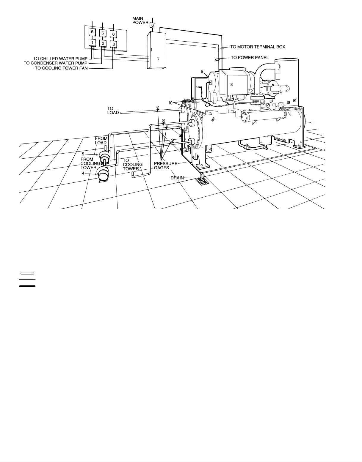
1—Chilled Water Pump Starter
2—Condenser Water Pump Starter
3—Cooling Tower Fan Starter
4—Chilled Water Pump
5—Condenser Water Pump
6—Disconnect
7—Vents
Piping
Control Wiring
Power Wiring
Fig. 27 — Typical 23XL with Optional Unit Mounted Starter (Frame 1 and 2 Machines)
NOTES:
1. Wiring and piping shown are for general point-of-connection only and are not
intended to show details for a specific installation. Certified field wiring and dimensional diagrams are available on request. 23XL machines should be installed using certified drawings.
2. All wiring must comply with applicable codes.
3. Refer to Carrier System Design Manual for details regarding piping techniques.
4. Wiring not shown for optional devices such as:
• remote start/stop
• remote alarm
• optional safety device
• 4 to 20 mA resets
• optional remote sensors
27
Page 28
LEGEND
1—Chilled Water Pump Starter
2—Condenser Water Pump Starter
3—Cooling Tower Fan Starter
4—Condenser Water Pump
5—Chilled Water Pump
6—Disconnect
7—Freestanding Compressor Motor Starter
8—Compressor Motor Terminal Box
9—Power Panel (Hidden)
10 — Vents
Piping
Control Wiring
Power Wiring
Fig. 28 — Typical 23XL with Free-Standing Starter (Frame 1 and 2 Machines)
NOTES:
1. Wiring and piping shown are for general point-of-connection only and are not
intended to show details for a specific installation. Certified field wiring and dimensional diagrams are available on request. 23XL machines should be installed using certified drawings.
2. All wiring must comply with applicable codes.
3. Refer to Carrier System Design Manual for details regarding piping techniques.
4. Wiring not shown for optional devices such as:
• remote start/stop
• remote alarm
• optional safety device
• 4 to 20 mA resets
• optional remote sensors
28
Page 29

IMPORTANT: Do not insulate terminals until wiring
arrangement has been checked and approved by
Carrier start-up personnel.Also, make sure correct phasing is followed for proper motor rotation.
INSULATE MOTOR TERMINALS AND LEAD WIRE
ENDS — Insulatecompressor motor terminals, lead wire ends,
and electrical wires to prevent moisture condensation and
electrical arcing. Obtain insulation material from machine
shipping package (located inside the motor terminal box) consisting of 3 rolls of insulation putty and one roll of vinyl
tape.
1. Insulate each terminal by wrapping with one layer of insulation putty.
2. Overwrap putty with 4 layers of vinyl tape.
NOTE: Installer is responsible for any damage caused by
improper wiring between starter and compressor motor.
CONNECT POWER WIRE TO OIL HEATER CONTAC-
→
TOR (FRAME 1 AND 2) — Connect control power wiring
between the oil heater contactor terminals (Fig. 29) and
terminals LL1 and LL2 on the field wiring strip in the
compressor motor starter. Refer to Fig. 29 and wiring label
on the chiller power panel
Voltage to terminals LL1 and LL2 comes from a control transformer in a starter built to Carrier specifications. Do not connect an outside source of control
power to the compressor motor starter (terminals LL1
and LL2). An outside power source will produce dangerous voltage at the line side of the starter, because
supplying voltage at the transformer secondary terminals produces input level voltage at the transformer
primary terminals.
The optional hot gas bypass valve is factory wired for
115 volts. If 230 v is used for control voltage, disconnect the red wire from the piggy-back terminal oil heater
contactor terminal 23 and yellow wire from the piggyback on pilot relay 3C terminal No. 4. Then connect
the red and yellow wires together with a splice
connector.
CARRIER COMFORT NETWORK INTERFACE — The
Carrier Comfort Network (CCN) communication bus wiring
is supplied and installed by the controls/electrical contractor
(if required). The wiring consists of shielded, 3-conductor
cable with drain wire.
The system elements are connected to the communication
bus in a daisy chain arrangement. The positive pin of each
system element communication connector must be wired to
the positive pins of the system element on either side of it.
The negative pins must be wired to the negative pins. The
signal ground pins must be wired to the signal ground pins.
See Fig. 30 for location of the CCN network connector
(COMM1) on the processor module.
NOTE: The voltage selector switch in the machine power
panel is factory set for 115 v control power source. When a
230 v control power source is used, set the voltage selector
switch at 230 v.
LEGEND
Field Wiring
Power Panel Component Terminal
Fig. 29 — Oil Heater and Control Power
Wiring Diagram (Frame 1 and 2 Machines)
CONNECT COMMUNICATION AND CONTROL WIRING FROM STARTER TO POWER PANEL — Connect
control wiring from main motor starter to the machine power
panel. All control wiring must use shielded cable. Also,
connect the communications cable. Refer to the job wiring
diagrams for cable type and cable number. Make sure the
control circuit is grounded in accordance with applicable
electrical codes and instructions on machine control wiring
label.
Fig. 30 — Carrier Comfort Network
Communication Bus Wiring
NOTE: Conductors and drain wire must be 20 AWG
(American Wire Gage) minimum stranded, tinned copper. Individual conductors must be insulated with PVC,
PVC/nylon, vinyl, Teflon, or polyethylene. An aluminum/
polyester 100% foil shield and an outer jacket of PVC, PVC/
nylon, chrome vinyl, or Teflon with a minimum operating temperature range of −4 F to 140 F (−20 C to 60 C)
is required. See table below for cables that meet the
requirements.
MANUFACTURER CABLE NO.
Alpha 2413 or 5463
American A22503
Belden 8772
Columbia 02525
29 796
Page 30

When connecting the CCN communication bus to a system element, a color code system for the entire network is
recommended to simplify installation and checkout. The following color code is recommended:
SIGNAL TYPE
+ Red 1
Ground White 2
− Black 3
CCN BUS CONDUCTOR
INSULATION COLOR
COMM1 PLUG
PIN NO.
If a cable with a different color scheme is selected, a similar color code should be adopted for the entire network.
At each system element, the shields of its communication
bus cables must be tied together. If the communication bus
is entirely within one building, the resulting continuous shield
must be connected to ground at only one single point. See
Fig. 31. If the communication bus cable exits from one building and entersanother, the shields must be connected to ground
at the lightening suppressor in each building where the cable
enters or exits the building (one point only).
To connect the 23XL chiller to the network, proceed as
follows (Fig. 31):
1. Cut power to the PIC control center.
2. Remove the COMM1 plug from the processor module.
3. Cut a CCN wire and strip the ends of the RED, WHITE,
and BLACK conductors.
4. Using a wirenut, connect the drain wires together.
5. Insert and secure the RED wire to Terminal 1 of the
COMM1 plug.
6. Insert and secure the WHITE wire to Terminal 2 of the
COMM1 plug.
7. Insert and secure the BLACK wire to Terminal 3 of the
COMM1 plug.
8. Mount a terminal strip in a convenient location.
9. Connect the opposite ends of each conductor to separate
terminals on the terminal strip.
10. Cut another CCN wire and strip the ends of the
conductors.
11. Connect the RED wire to the matching location on the
terminal strip.
12. Connect the WHITE wire to the matching location on
the terminal strip.
13. Connect the BLACK wire to the matching location on
the terminal strip.
Install Field Insulation
Protect insulation from weld heat damage and weld splatter. Cover with wet canvas cover during water piping
installation.
When installing insulation at the job site, insulate the fol-
lowing components:
• compressor motor
• cooler shell
• cooler tube sheets
• suction piping
• motor cooling drain
• oil reclaim piping (Frame 1 and 2 machines only)
• cooler liquid inlet piping
• hot gas bypass piping (if applicable)
• economizer and economizer piping (if applicable)
Insulation of the waterbox covers is applied only at the
jobsite. When insulating the covers, make sure there is access for removal of waterbox covers for servicing (Fig. 32
and 33).
Depending upon humidity conditions, field insulation of
the condenser’s bottom half may be required when the machine is not operating.
F ACT ORY-INSTALLED INSULATION (OPTIONAL) — Optional, factory-installed insulation is available for the evaporator shell and tube sheets, suction pipe, compressor motor,
refrigerant lines, oil reclaim piping, hot gas bypass (if applicable), and economizer and economizer piping (if applicable). The insulation is
3
⁄4-in. (19 mm) thick.
30
Page 31

23XL CHILLER 23XL CHILLER 23XLCHILLER
LEGEND
Factory Wiring
Field Wiring
*Field supplied terminal strip must be located in the control center.
Fig. 31 — Typical COMM1 CCN Communication Wiring for Multiple Chillers
31
Page 32

→
Fig. 32 — 23XL Insulation Area for Frame 1 and 2 Machines
→
796 32
Fig. 33 — 23XL Insulation Area for Frame 4 Machines
Page 33

IMPORTANT: Refer to certified drawings for additional information. Certifieddrawings are available upon
request.
LEGEND
Required Power Wiring
Required Control Wiring
Options Wiring
NOTES:
I. GENERAL
1.0 Starters shall be designed and manufactured in accordance with
Carrier Engineering Requirement Z-375.
1.1 All field-supplied conductors, devices, field-installation wiring, and termination of conductors and devices, must be in compliance with all
applicable codes and job specifications.
1.2 The routing of field-installed conduit and conductors and the location
of field-installed, devices must not interfere with equipment access or
the reading, adjusting, or servicing of any component.
1.3 Equipment installation and all starting and control devices must comply with details in equipment submittal drawings and literature.
1.4 Contacts and switches are shown in the position they would assume
with the circuit deenergized and the chiller shut down.
1.5 WARNING — Do not use aluminum conductors.
II. POWER WIRING TO STARTER
2.0 Power conductor rating must meet minimum unit nameplate voltage
and compressor motor RLA (rated load amps).
When (3) conductors are used:
Minimum ampacity per conductor = 1.25 x compressor RLA
When (6) conductors are used:
Minimum ampacity per conductor = 0.721 x compressor RLA
2.1 Lug adaptersmay be required if installationconditions dictate that conductors be sized beyond the minimum ampacity required. Solid-state
starters are provided with:
A. Two (2) 0-250 MCM lugs provided per phase for power conductor
terminations when compressor motor RLA is 400 amps or less.
B. Three (3), 250-500 MCM lugs provided per phase for power con-
ductor terminations when compressor motor RLA is more than
400 amps.
Wye-Delta starters are provided with:
A. Two (2) 250-500 MCM lugs provided per phase for power conduc-
tor terminators when compressor motor RLA is 420 amps or less.
B. Two (2) #1-500 MCM lugs provided per phase for power conductor
terminations when compressor motor RLA is more than
420 amps.
2.2 Power conductors to starter must enter through top of enclosure. Flexible conduit should be used for the last few feet to the enclosure to
provide unit vibration isolation.
2.3 Compressor motor and controls must be grounded by using equipment grounding lugs provided inside starter enclosure.
2.4 Wye-Delta starters require the assembly and the installation of a ‘‘Top
Hat’’ (located inside enclosure) to provide the required wire bending
space for incoming power leads.
III. CONTROL WIRING
3.0 Field supplied control conductors to beat least 18AWG(AmericanWire
Gage) or larger.
3.1 Chilled water and condenser water flow switch contacts, optional remote start device contacts and optional spare safety device contacts,
must have 24 vdc rating. Max current is 60 ma, nominal current
is 10 ma. Switches with gold plated bifurcated contacts are
recommended.
3.2 Remove jumper wire between 12A and 12B before connecting auxiliary safeties between these terminals.
3.3 Pilot relays can control cooler and condenser pump and tower fan motor contactor coil loads rated 10 amps at 115 vac up to 3 amps at 600
vac. Control wiring required for Carrier to start pumps and tower fan
motorsmust be providedto assure machineprotection. If primarypump
and tower fan motor control is by other means, also provide a parallel
means for control by Carrier. Do not use starter control transformer as
the power source for pilot relay loads.
3.4 Do not route control wiring carrying 30 v or less within a conduit which
has wires carrying 50 v or higher or along side wires carrying 50 v or
higher.
Fig. 34 — 23XL Typical Field Wiring with Optional Unit-Mounted Starter (Frame 1 and 2 Machines Shown)
33
Page 34

IMPORTANT: Wiring shown is typical and not intended to show detail
for a specific installation. Refer to certified field wiring diagrams for
additional information. Certified drawings are available upon request.
Required Power Wiring Options Wiring
Required Control Wiring
NOTES:
I. GENERAL
1.0 Starters shall be designed and manufactured in accordance with Carrier Engineering Requirement Z-375.
1.1 All field-supplied conductors, devices, field-installation wiring, and termination of
conductors and devices, must be in compliance with all applicable codes and job
specifications.
1.2 The routing of field-installed conduit and conductors and the location of fieldinstalled devices, must not interfere with equipment access or the reading, adjusting, or servicing of any component.
1.3 Equipment, installation, and all starting and control devices must comply with details in equipment submittal drawings and literature.
1.4 Contacts and switches are shown in the position they would assume with the circuit
deenergized and the chiller shut down.
1.5 WARNING — Do not use aluminum conductors.
1.6 Installer is responsible for any damage caused by improper wiring between starter
and machine.
II. POWER WIRING TO STARTER
2.0 Power conductor rating must meet minimum unit nameplate voltage and compressor motor RLA (rated load amps).
When (3) conductors are used:
Minimum ampacity per conductor = 1.25 x compressor RLA
When (6) conductors are used:
Minimum ampacity per conductor = 0.721 x compressor RLA
2.1 Lug adapters may be required if installation conditions dictate that conductors be
sized beyond the minimum ampacity required. Contact starter supplier for lug
information.
2.2 Compressor motor and controls must be grounded by using equipment grounding
lugs provided inside starter enclosure.
III. CONTROL WIRING
3.0 Field supplied control conductors to be at least 18 AWG (American Wire Gage) or
larger.
3.1 Chilled water and condenser water flow switch contacts, optional remote start
device contacts and optional spare safety device contacts, musthave 24 vdc rating.
Max current is 60 ma, nominal current is 10 ma. Switches with gold plated
biurcated contacts are recommended.
3.2 Remove jumper wire between 12A and 12B before connecting auxiliary safeties between these terminals.
→
Fig. 35 — 23XL Typical Field Wiring with Free-Standing Starter (Frame 1 and 2 Machines Shown)
LEGEND
3.3 Pilot relays can control cooler and condenser pump and tower fan motor contactor
coil loads rated 10 ampsat 115vac up to 3 ampsat 600 vac. Control wiringrequired
for Carrier to start pumps and towerfan motors must be provided toassure machine
protection. If primary pump and tower fan motor control is by other means, also
provide a parallel means for control by Carrier. Do not use starter control transformer as the power source for pilot relay loads.
3.4 Do not route control wiring carrying 30 v or less within a conduit which has wires
carrying 50 v or higher or along side wires carrying 50 v or higher.
3.5 Voltage selector switch in machine powerpanel is factory set for 115 v control power
source. When 230 v control power source is used, set switch to 230 v
position.
3.6 Control wiring cables between starter and power panel must be shielded with minimum rating of 600 v, 80 C. Ground shield at starter.
3.7 Voltage to terminals LL1 and LL2 comes from a control transformer in a starter built
to Carrier specifications. Do not connect an outside source of control power to the
compressor motor starter (terminals LL1 and LL2). An outside power source will
produce dangerous voltage at the lineside of the starter, because supplying voltage
at the transformer secondary terminals produces input level voltage at the transformer primary terminals.
IV. POWER WIRING BETWEEN STARTER AND COMPRESSOR MOTOR
4.0 Low voltage (600 v or less) compressor motors have (6)1⁄2in. terminal studs (lead
connectors not supplied by Carrier). Either 3 or 6 leads must be run between compressor motor and starter, depending on type of motor starter employed. If only 3
leads are required, jumper motor terminals as follows: 1 to 6, 2 to 4, 3 to 5. Center
to center distance between terminals is 2.73 inches.Compressor motor starter must
have nameplate stamped as to conforming with Carrier requirement ‘‘Z-375.’’
4.1 When more than one conduit is used to run conductors from starter to compressor
motor terminal box, one conductor from each phase must be in each conduit, to
prevent excessive heating. (e.g., conductors to motor terminals 1, 2 and 3 in one
conduit, and these to 4, 5 and 6 in another.)
4.2 Compressor motor power connections can be made through top, bottom, or right
side of compressor motor terminal box by rotating the terminal box and using holes
cut by contractor to suitconduit. Flexible conduit should be used for the lastfew feet
to the terminal box for unit vibration isolation. Use of stress cones or 12 conductors
larger than 500 MCM may require an oversize (special) motor terminal box (not
supplied by Carrier). Lead connections between 3-phase motors and their
starters must not be insulated until Carrier personnel have checked compressor
rotation.
4.3 Compressor motor frame to be grounded in accordance with the National Electrical
Code (NFPA-70) and applicable codes. Means for grounding compressor motor is
(2) Thomas and Betts pressure connectors for 350 to 800 MCM wire, supplied and
located in the back upper and lower right side corners of the compressor motor
terminal box.
4.4 Do not allow motor terminals to support weight of wire cables. Use cable supports
and strain reliefs as required.
4.5 Use back up wrenchwhentighteningleadconnectors to motor terminal studs. Torque
to 10-15 lb-ft maximum.
Copyright 1994 Carrier Corporation
Manufacturer reserves the right to discontinue, or change at any time, specifications or designs without notice and without incurring obligations.
Book 2
PC 211 Catalog No. 532-303 Printed in U.S.A. Form 23XL-2SI Pg 34 796 9-94 Replaces: 23XL-1SI
Tab 5e
Page 35

INSTALLATION START-UP REQUEST CHECKLIST
Machine Model Number: 23XL Serial Number:
CUT ALONG DOTTED LINE
To:
Date
Project Name
Attn:
Carrier Job Number
The following information provides the status of the chiller installation.
1. The machine is level.
2. The machine components are installed and connected in
accordance with the installation instructions.
3. The isolation package and grouting (if necessary)
are installed.
4. The relief valves are piped to the atmosphere.
5. All piping is installed and supported. Direction of flow
is indicated in accordance with the installation instructions
and job prints.
a. Chilled water piping
b. Condenser water piping
c. Waterbox drain piping
d. Pumpout unit condenser piping (if installed)
e. Other
6. Gages are installed as called for on the job prints required
to establish design flow for the cooler and condenser.
a. Water pressure gages IN and OUT
b. Water temperature gages IN and OUT
7. The machine’s starter wiring is complete. The wiring is
installed per installation instructions and certified prints.
a. Power wiring to compressor motor. (Motor leads will
not be taped until the Carrier technician megger tests
the motor.)
b. Oil heater/control wiring (if applicable)
c. Other
8. The motor starter has not been supplied by Carrier. It
has been installed according to the manufacturer’s
instructions.
9. The motor starter has not been supplied by Carrier and it
has been checked for proper operation.
COMMENTS:
YES/NO
(N/A)
DATE TO BE
COMPLETED
CL-1
----------------------------------------------------------------------------------------
Page 36

TESTING YES/NO
1. The cooling tower fan has been checked for blade pitch and
proper operation.
2. The chilled water and condenser water lines have been:
a. Filled
b. Tested
c. Flushed
d. Vented
e. Strainers cleaned
3. The chilled water and condenser water pumps have been
checked for proper rotation and flow.
4. The following cooling load will be available for start-up:
a. 25%
b. 50%
c. 75%
d. 100%
5. The refrigerant charge is at the machine.
6. Services such as electrical power and control air will be available at start-up.
7. The electrical and mechanical representatives will be available
to assist in commissioning the machine.
8. The customer’s operators will be available to receive instructions for proper operation of the chiller after start-up.
DATE TO BE
COMPLETED
Concerns about the installation/request for additional assistance:
I am aware that the start-up time for a Carrier chiller can take between 2 and 6 days depending on the model of the machine and
the options and accessories used with it.
Your contact at the job site will be
Phone number
Beeper number
Fax number
In accordance with our contract, we hereby request the services of your technician to render start-up services per contract terms
for this job on (Date). I understand that the technician’s time will be charged as extra services due to correcting items
in this checklist that are incomplete or damaged during rigging or shipping.
Signature of Purchaser
Signature of Job Site Supervisor
Copyright 1994 Carrier Corporation
Manufacturer reserves the right to discontinue, or change at any time, specifications or designs without notice and without incurring obligations.
Book 2
Tab 5e
PC 211 Catalog No. 532-303 Printed in U.S.A. Form 23XL-2SI Pg CL-2 796 9-94 Replaces: 23XL-1SI
 Loading...