

Page 1
Carrier
Start-Up instructions
OSso/c/e. ‘»nd oo /or7^er
S//ó/^/ z^k^/ {do record r) {
19DA
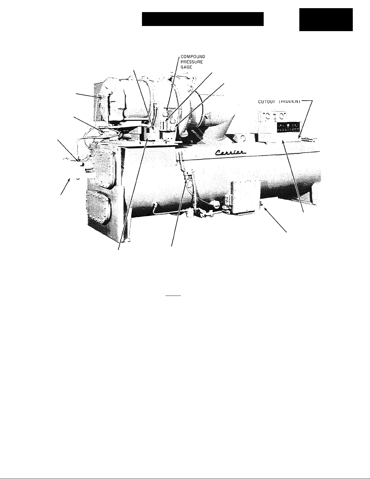
OIL HEATER INDICATOR LIGHT
MOTOR
ROTATION
SIGHT GLASS
LOW OIL PRESSURE
SWITCH
OIL PRESSURE
GAGE
eX
OIL PUMP JL,
ASSEMBLY^
OIL CHARGING
VALVE
---------------------
f—?iii;
a
OIL THERMOSTAT
(HIDDEN)
dr^'^S fcr /~o ôhiio/ô/e {ak)/o^ ZiÂ* )
OIL LEVEL SIGHT GLASS
OIL TEMPERATURE GAGE
REFRIGERANT
LOW TEMP CUTOUT
Fig. 1 - 19DA Hermetic Refrigeration Machine
CONDENSER HIGH-PRESSURE
ANTIRECYCLE
TIMER (HIDDEN)
COOLER
CHARGING
VALVE
INTRODUCTION
General - Use this booklet as a guide for initial
start-up of the 19DA Hermetic Centrifugal Re
frigeration Machine. Read and fully understand
these instructions plus all necessary Job Data
before beginning initial start-up. Instructions are
given in the proper sequence for optimum ma
chine performance.
Job Data Required
1. Machine assembly prints
2. Wiring diagrams
3. Starter details
4. 19DA Installation Instructions
5. 19DA Operation and Maintenance Instructions
Equipment and Materials Required
1. Mechanics' tools
2. Volt-ohmmeter
3. Carrier refrigerant drum charging valve
4. 5/8" SAE X 3/4" MPT cooler charging adapter
5. Five to ten ft of copper tubing or plastic hose
6. Halide or electronic leak detector
7. Low-pressure indicator
a. Absolute pressure manometer
b. Wet-bulb indicator
8. Clamp-on ammeter
9. Portable dehydration pump
INITIAL PREPARATIONS
CAUTION: Do not operate refri^rant pump
unless machine is charged with refrigerant.
Do nor start compressor or oil pump, even for
a rotation check, while machine is at vacuum.
Check rotation only after compressor has been
charged with oil and machine has been charged
with refrigerant.
Machine Tightness - A shipping vacuum was ap
plied to the refrigerant side of the 19DA machine
before shipment from the factory. Over a period
of time, during shipment or storage, part of this
vacuum may be lost. The loss of a small amount
of vacuum may be acceptable and within Carrier's
machine tightness standards. To determine if the
vacuum loss is acceptable or not requires the
following steps:
© Carrier Corporation 1966
Form 19DA-1SS
Page 2

PURGE PUMP
SWITCH
CHILLED WATER
LOW TEMP CUTOUT
PURGE VALVE OPERATION PLATE
PURGE OPERATING VALVES (6)
Fig. 2 - 19DA Rear View
Record and date vacuum reading shown on
1.
compound pressure gage located on compres
sor (Fig. 1).
With this reading and the reading taken when
2.
the machine was received, determine vacuum
leak rate using the following formula:
Leak Rate = Vacuum loss
H- No. of days between readings
3. If vacuum leak rate is 0.05 in. Hg or less per
24 hours, the machine is sufficiently tight.
If vacuum leak rate exceeds this rate, per
form "Refrigerant Pressure Test” and cor
rect leakage.
EXCESSIVE OR TOTAL VACUUM LOSS - Ex
cessive or total vacuum loss can be caused by
accidental opening of a valve or other connec
tion. If this is suspected, proceed as follows:
1. Install a mercury manometer (absolute pres
sure type) to the cooler charging valve (Fig. 1).
A dial type gage can not indicate the small
amount of leakage acceptable during a short
period of time.
2. Pull a vacuum on the machine equal to 25 in.
Hg. Use external vacuum pump or energize
purge pump (Fig. 2) using operation No. 2
described on the purge valve operation plate
shown on Fig. 2.
3. Let the machine stand with this vacuum, and
then perform the leak rate check previously
outlined.
4. If the vacuum leak rate is 0.05 in. Hg or less
per 24 hours, the machine is sufficiently tight.
Perform all steps under "Machine Dehydra
tion" (pg 3).
5. If the vacuum leak rate exceeds 0.05 in. Hg
per 24 hours, perform all steps under "Re
frigerant Pressure Test" (pg 2) and correct
leakage. Perform all steps under "Machine
Dehydration."
6. Remove the mercury manometer from cooler
charging valve.
REFRIGERANT PRESSURE TEST
1. Pull approximately five inches of vacuum on
the machine by energizing machine purge pump
(Fig. 2). Use operation No. 2 described on the
purge valve operation plate or with an external
vacuum pump connected to the cooler charging
valve (Fig. 1).
2. Charge approximately one gallon of Refrig
erant 11 thru the cooler charging valve. Refer
to refrigerant charging instructions (pg 4).
3. Increase pressure to eight to ten psi with dry
air or nitrogen thru the cooler charging valve.
DO NOT EXCEED TEN PSI.
4. Test all joints, valves, fittings, flanges, etc.
with a halide or electronic leak detector.
CAUTION: Due to rupture disc limitations :
DO NOT EXCEED TEN PSI.
Page 3

5. Repair any leaks found.
6. Reinspect joints and flanges with the leak de
tector to ensure that all leaks have been found
and repaired.
Machine Dehydration - The refrigerant side of
the 19DA machine is dehydrated at the factory.
It is usually not necessary to repeat dehydration
at initial start-up. However, if the machine has
been open for a considerable length of time due
to compressor removal, or if there was excessive
loss of shipping vacuum, it is recommended that
dehydration be repeated.
WARMING: Do not start compressor or oil
pump even for a rotation check while machine ;
is under dehydration vacuum.
NOTE: Dehj'dration is rea'dily accomplished at
normal room temperature. If room temper
ature is high, dehydration takes pbace more
quickly. At low room temperature, dehydra
tion is extremely difficult and special tech
niques must be applied. Contact your Carrier
representative.
Perform dehydration as follows:
CHECK WATER FLOW RATE - Water flows thru
cooler and condenser must meet job require
ments. Measure water pressure drop across
cooler and condenser or across the pumps. Check
to see that water flow rates agree with the de
sign flow.
Follow the instructions on the caution tag
attached to the oil cooler which reads:
CAUTION: Clean water at 85 F maximum
temperature to be provided. Valves and/or
controls to limit the following:
Max inlet working press. 100 psi
Water vel in tube, ft/sec 10 max - 6 min ;
Water flow, gaL/min 7 max - 4 min :
Water press, drop, psi diff 5 max - 2 min ;
The necessary valves and/or controls are
field supplied.
Field Wiring - Prior to starting equipment, refer
to wiring diagrams provided in Job Data and
check power supply as follows:
1. Connect a voltmeter across power wires to
compressor motor starter and measure volt
age. Compare this reading with voltage rating
on compressor and starter nameplates.
1. Connect dehydration pump to the cooler charg
ing valve (Fig. 1).
2. Ensure that all valves on the purge assembly
are closed (Fig. 2). Purge valve Identification
numbers are found on the purge valve opera
tion plate at the valves.
3. Remove the A-B swing connection (shown under
Valve Locations on the purge valve operation
plate) and connect a mercury manometer (ab
solute pressure type) to the bottom common
connection.
4. Operate dehydration pump until manometer
reads 0.20 in. Hg (29.80 inches of vacuum
at 30 inches barometer); continue to operate
pump for two more hours.
5. Close cooler charging valve; stop dehydration
pump; record manometer reading.
6. After a two hour waiting period, take another
manometer reading. If reading has not in
creased, dehydration is complete. If reading
has increased, repeat steps 4 and 5.
7. If the reading continues to rise after several
dehydration attempts, suspect a machine leak.
If this is the case, repeat the refrigerant
pressure test.
2. Connect voltmeter across power wires to oil
pump starter and measure voltage. Compare
this reading with voltage rating on oil pump
nameplate.
3. Compare ampere rating on starter nameplate
with ampere rating on motor nameplate for
agreement.
4. Test motor and motor supply cable insulation
resistance using a five-hundred volt insulation
tester such as a megohmeter. Proceed as
follows:
a. Open starter main disconnect switch.
b. Test the three phases of compressor motor,
phase to phase, and phase to ground, with
tester connected on the motor side of the
starter contactor in the starter. Take re
sistance readings at ten-second and sixtysecond intervals for each phase.
c. Divide sixty-second resistance reading by
ten-second reading. This gives polarization
ratio. The polarization ratio must be 1.15
or higher. The ten-second and sixty-second
resistance readings must be 5.0 megohms
or higher.
Inspect Piping - Refer to piping diagrams pro
vided in Job Data and inspect chilled water piping,
condenser water piping, and water piping to oil
cooler. Ensure that flow direction is correct in
all cases and that all specified piping require
ments are met.
NOTE: The above procedure will check condi
tion of compres-sor motor and motor supply
cable insulation. If above requix'ements are
not met, repeat the test at motor terminals
with motor supply cables disconnected.
Page 4

Check Starter - Before starting the 19DA, check
starter as follows:
1. Remove the contactor arc chutes. Be sure con
tactors move freely, and that shipping string
has been removed. Replace arc chutes.
2. If starter has been left on jobsite for a consid
erable period of time, check contactors for
dirt and rust. Clean contact magnet surfaces
with emery cloth. Apply a very thin coating
of vaseline to magnet surfaces, then wipe it
off. If starter has been in a dusty atmosphere,
vacuum clean starter cabinet and wipe with a
lint-free cloth.
3. Remove fluid cups from magnetic overload
relays. Add dashpot oil to cups per instructions
on relay nameplate. Dashpot oil is shipped in
small vials usually attached to starter frame
near relays. Use only the dashpot oil shipped
with starter. Do not substitute. Overload re
lays are factory set for 111 percent of motor
full load amperage and resetting is not nor
mally required.
4. Check transfer timer for proper time setting.
On Star-Delta starters, timers have adjust
able ranges of ten seconds to three minutes
and are factory set for one minute. On Auto-
Transformer starters, timers have adjustable
ranges of ten to forty seconds and are factory
set for thirty seconds.
5. With main disconnect switch open, manually
open and close main control relay (ICR) to be
sure it operates freely.
Charge Oil - Use oil shipped with the machine.
Any substitute must meet Carrier's oil specifica
tion outlined in 19DA Operation and Maintenance
Instructions.
Charge oil thru the oil reservoir charging
valve (Fig. 1). With machine at vacuum, oil is
drawn from the oil container. Continue charging
until oil reaches middle of sight glass (Fig. 1).
3/4 GLOBE
VALVE
5/8"SAE FLARE x
3/4"MPT ADAPTER
Fig. 3 - Drum Charging Valve and Fitting
3. Start chilled water pump and circulate chilled
water during charging process.
4. If machine pressure is eighteen inches of mer
cury (32 F) vacuum or lower, keep refrigerant
drum upright, open valves and admit refrig
erant gas to cooler. The machine under vacuum
will boil off liquid refrigerant, and raise ma
chine pressure, preventing possible freeze-up.
5. Charge the machine with the proper quantity
of refrigerant for the machine size given on
a tag attached to the cooler charging valve
(Fig. 1) or in Table 1.
NOTE: The refrigerant supplied v/ith this ?
machine is in excess of that required for ^
initial charging. Use the correct amount as
shown in T^>ie 1.
The machine under vacuum will draw refrig
erant from the drum.
6. After machine has been started, it may be
necessary to adjust refrigerant charge for
optimum machine performance.
/5
I
CAUTION: After charging oil, energize the
oil heater to minimize absorption of refrig
erant by the oil. The oil heater indicator light
(Fig. 1) comes on when heater is energized.
Set oil heater thermostat (Fig. 1) to maintain s
a minimum oil reservoir temperature of 145 F i
at shutdown.
Charging Refrigerant - To charge the 19DA ma
chine, proceed as follows:
1. Install a charging valve on the 3/4-inch drum
opening as shown in Fig. 3. When the 3/4-inch
pipe nipple is screwed into the drum opening,
the nipple forces the bottle cap off its seat.
2. Connect a short piece of clear plastic hose or
copper tubing from drum valve to cooler charg
ing valve located beneath float chamber.
NOTE: Refer to "Trimming Refrigerant
Charge” (pg II) for full load adjustment.
Table 1 - Charging Quantity
MACHINE
CHARGING
MACHINE
SIZE WT (lbs) SIZE
19DA-102
19DA-112 400
19DA-131
19DA-147 450
400
425
19DA-228
19DA-255
19DA-284
19DA-325
19DA-160 525 19DA-362
19DA-182 550 19DA-397
19DA-198 575
CHARGING
WT (lbs)
575
850
880
900
935
960
Page 5

Check Operation of Safety Controls - Disconnect
main motor leads at starter to prevent compressor
motor operation while performing safety control
check. Push the START button. Manually open
.f
the following safety controls to be sure they de
energize the ICR coil, causing the main starter
contacts to open and stop the compressor. Anti
recycle timer, item 6, Table 2, can be set for
minimum time per this safety check.
1. Chilled water low-temperature cutout and re
cycle switch (item 1, Table 2).
2. Chilled water flow switch (in chilled waterline).
3. Refrigerant low-temperature cutout switch
(item 2, Table 2).
4. Low oil pressure cutout switch (item 5, Table 2).
5. Condenser high-pressure cutout switch (item 4,
Table 2).
6. Bearing and motor winding high-temperature
cutout switch (in motor terminal box - remove
one wire to OPEN switches).
7. Oil pump starter auxiliary contact (in oil pump
starter).
8. Chilled water and condenser water pump safety
interlocks (in pump starters).
9. Any other interlock shown on job blueprint.
Purge - Open all purge operating valves (Fig. 2).
Place valves in NORMAL AUTOMATIC position.
Operate purge pump momentarily by placing purge
switch in MANUAL position. Then place purge
switch in AUTO position.
compressor motor come up to speed, then press
machine STOP button. Check motor rotation thru
sight glass in the motor end bell (Fig. 1). Motor
rotation must be clockwise to result in coun
terclockwise rotation of the compressor (when
viewed from motor end).
COMPRESSOR OPERATION
1. Press machine START button and let com
pressor come up to speed. Press machine
STOP button and listen for any unusual sounds
coming from the compressor and transmission
housing as compressor coasts to a stop.
NOTE: The antirecycietimerprevents rapid
recycling of the compressor and is factory
set to allow one start every twenty minutes, ;
2. Press machine START button and let compres
sor continue running. Check oil pressure and
oil temperature (Fig. 1).
3. Ensure that condenser water and chilled water
are circulating, and that chilled water tem
perature does not drop below the design tem
perature shown in Job Data.
4. Ensure that the refrigerant agitator solenoid
valve(s) are operating. The agitator valve(s)
are open when the inlet guide vanes are closed.
When the vanes open, and the vane motor crank
angle reaches approximately 42° from the ver
tical centerline, the valve closes. The two
valves on the 19DA31 size compressor operate
in step sequence at approximately 42° and 28°
vane motor crank angle.
While the inlet guide vanes are being opened
START-UP
Preliminary Checks
WATER SUPPLY - Before checking compressor
rotation, ensure that water supplies to the cooler,
condenser, and oil cooler are available, and that
the water pumps are running.
COMPRESSOR ROTATION - Set capacity control
to MANUAL (Honeywell), or HOLD (BarberColman). Press machine START button and let
manually (see "Motor Overload Module"),
listen for the sound of the refrigerant agitator
solenoid valve(s) closing.
Setting Safety Controls - Before setting safety
controls, set the capacity control to MANUAL
(Honeywell) position or HOLD (Barber-Colman).
Place a clamp-on ammeter on one of the three
starter leads and slowly open prewhirl vanes.
(Do not exceed 100 percent full load amperage.)
Perform the safety checks in the following table;
Table 2 - Setting Safety Controls
SAFETY OR CONTROL DEVICE RECOMMENDED SETTING
1. Chilled Water Low-Temperature
Cutout and Recycle Switch (Fig. 2)
-TEMPERATURE ADJUSTMENT
1. Set this switch to break at approximately 5 F below de
sign chilled water temperature, or at 36 F, whichever
is higher.
2. Set the differential at 10 F plus or minus 1 F so that
when the machine shuts down automatically at approx
imately 5 F below the design chilled water temperature
it will restart at approximately 5 F above the design
water temperature.
3. This control must break ahead of the refrigerant lowtemperature cutout switch or the machine will not re
cycle automatically.
Page 6

Table 2 - Setting Safety Controls (Contd)
SAFETY OR CONTROL DEVICE RECOMMENDED SETTING
2. Refrigerant Low-Temperature
Cutout (Fig. 1)
1. Install jumper wire or mechanical block in the chilled
water low-temperature cutout and recycle control.
2. Set the refrigerant low-temperature cutout at 33 F while
reading the temperature gage on side of float chamber.
3. Remove jumper wire or block.
3. Oil Heater Thermostat (Fig. 1)
4. Condenser High-Pressure
Cutout (Fig. 1)
CUTOUT ADJUSTMENT .-••c '
COVER-
„
......
........... , BUTTON
CUTOUT SCALE
RESET
5. Low Oil Pressure Cutout (Fig. 1)
RANGE (CUT-IN) .
DIAL ADJUSTMENT
REMOVE METAL
COVER
------
CUTOUT
ADJUSTMENT
Set the oil heater thermostat to maintain a minimum oil
reservoir temperature of 145 F at shutdown.
The condenser high-pressure cutout switch is factory set
to shut the machine down when the condenser pressure
reaches approximately fifteen psig. Isolate the switch, and
check switch setting with a metered supply of air.
Opens switch contacts on drop in oil pressure. Cutout at
9 psi differential. Cut-in at 14 psi differential. While op
erating pump manually, note and record reservoir pres
sure on gage. Remove cap and gasket from oil pressure
regulating valve. Loosen locknut. Turn adjusting screw
counterclockwise to lower oil pressure to within 4 psi of
reservoir pressure. Reset differential to adjust cutout. Set
range (cut-in) by turning adjusting dial clockwise, raising
oil pressure.
6. Antirecycle Timer (Fig. 1)
/TIME SETTING
'LOCKNUT
' N
TIMER
SWITCHES
Time setting is factory set for 20 minutes. Limits the num
ber of machine starts to three per hour.
Page 7

Calibrating Electronic Controls - Honeywell (Fig. 4) or Barber-Colman (Fig. 5)
Table 3 - Motor Overload Module
m
SEQUENCE
1. Check Voltage Signal
from current trans
former - (leads
disconnected)
2. Recheck voltage
signal (leads
connected)
B-C
H
X
X
X
X
X
X
X
A. Shut down compressor:
X
X
X
1. Rotate CRl (6) and CR2 (7) calibration screws fully clockwise.
2. Disconnect leads to terminals 23 and 24 on terminal strip.
3. Place clamp on ammeter on one of three incoming starter wires.
X B. Start compressor:
X
1. Press START button.
2. Open vanes manually by depressing INCREASE button (5).
X
3. Place the capacity control switch (15) on HIGHER position to
NOTE; At- iOO percent Ml load current^ voltmeter must
read at least 0.55 volts. If not in this range, check sizing
of resistor in starter.
X
X
X
X
X
X
A. Shut down compressor:
X
X
X
X
1. Remove voltmeter from leads.
2. Replace leads to terminals 23 and 24.
3. Attach voltmeter to terminals 23 and 24.
B. Start the compressor:
1. Open vanes manually. Voltmeter must read between 0.45-0.55
X
X
X
X
2. Press STOP button and remove voltmeter.
PROCEDURE
Attach voltmeter to these leads.
open vanes manually.
volts at 100 percent full load current.
3. Calibrate motor
current settings
(compressor
operating)
H = Honeywell
B-C = Barber-Colman
A. Barber-Colman:
X
X
1. Open vanes manually until motor current reaches 108 percent
of nameplate current.
2. Adjust CRl calibration screw (6) until vanes begin to close.
Observe movement of vane motor linkage.
3. Set capacity control switch (15) on HIGH. When motor reaches
X
103 percent of full load amperage, adjust CR2 calibration
screw (7) until vanes stop moving.
B. Honeywell:
1. When motor current reaches 103 percent of rated amperage,
X
adjust calibration screw (18) until relay CR2 (23) is open and
relay CRl (22) is closed.
2. Hold relay CR2 (23) closed, and open vanes with INCREASE
X
button (5). When motor current reaches 108 percent of rated
amperage, relay CRl (22) should open.
C. Honeywell and Barber-Colman:
X
X
1. Close vanes and open again to recheck 103 percent and 108
percent settings.
Page 8

Calibrating Electronic Controls - Honeywell Only (Fig. 4)
Table 4 - Chilled Water Module
SEQUENCE
1. Set Differential
Adjustment
2. Calibrate Chilled
Water Temperature
Setting
3. Adjust Capacity
Balance
4. Observe Automatic
Operation
PROCEDURE (Compressor Operating)
A. Place capacity control switch (8) in MANUAL position.
B. Set throttling range screw (19) on counterclockwise stop.
C. Operate machine manually until leaving chilled water temperature is
within the range of the chilled water thermostat (35 F to 55 F).
D. Adjust differential screw (15) for a 3/4 F movement of the chilled water
thermostat (4) between the operation of relay CRO (25) and CRC (24).
A. Open vanes manually until chilled water temperature reaches design
temperature. Place chilled water thermostat in center of dial. (Lowest
division on left corresponds to 35 F. Each division represents IF.)
B. Adjust calibration screw (17) until relay CRC (24) is closed and relay
CRO (25) is open.
A. Connect an a-c voltmeter across test jack (21) and terminal J28. Use
50- or 60-volt scale.
B. Turn chilled water thermostat (4) clockwise or counterclockwise to
obtain lowest voltage reading on voltmeter.
C. Turn capacity balance screw (16) clockwise or counterclockwise until
voltage decreases further.
D. Repeat above steps to decrease voltage to approximately one volt.
A. Place capacity control (8) on THERMO position and thermostat (4) at
design chilled water temperature.
B. Turn throttle range screw (19) clockwise 1/3 of its total travel if chilled
water temperature "hunts.”
C. Recalibrate as in sequences 1 thru 4.
Calibrating Electronic Controls - Barber-Colman Only (Fig. 5)
Table 5 - Chilled Water Module
SEQUENCE
1. Adjust Capacity
Balance
A. Rotate throttling range screw (17) to counterclockwise position.
B. Operate vanes manually until chilled water temperature drops to design
PROCEDURE (Compressor Operating)
temperature.
C. Place capacity control switch (15) on HOLD.
D. Set chilled water thermostat (3) to dial center. (Lowest division on left
corresponds to 35 P. Each division represents IE.)
E. Connect COMMON plug of an a-c voltmeter to terminal X on amplifier
and other plug to terminal T. Use 12-volt scale.
F. Adjust temperature bridge calibration screw (18) until voltage becomes
minimum.
G. Adjust capacity balance screw (16) until voltage decreases further. Re
peat steps above to decrease voltage to one volt or lower.
H. Remove voltmeter.
2. Differential Setting
NOTE: A differential resistor is factor^'installed between terminals X
and Y (10) OR the cMlled water amplifier to give approximately 1 F dif- ;
ferential between the operation of microrelays CRC and CRO (19).
3. Observe Automatic
Operation
A. Place capacity control switch (15) on AUTO position.
B. Rotate throttling range screw (17) clockwise 1/3 of total travel if chilled
water temperature "hunts."
NOTE: If timottling range is added, recalibrate as in sequences 1 thru 3.
Page 9

1 ELECTRONIC CONTROL ON-OFF SWITCH
a MACHINE START BUTTON
3 VANE DECREASE BUTTON
4 CHILLED WATER THERMOSTAT
5 VANE INCREASE BUTTON
6 MACHINE STOP BUTTON
7 OIL PUMP AUTO-MANUAL SWITCH
8 CAPACITY CONTROL THERMOSTATIC-MANUAL
SWITCH
9 3-AMP FUSE - SAFETY CONTROL CIRCUIT
10 3-AMP FUSE - REFRIGERANT PUMP
11 OIL PUMP TIME DELAY RELAY
12 RELAY R-4
13 RELAY R-2
14 RELAY R-1
15 DIFFERENTIAL ADJUSTING SCREW
16 CAPACITY BALANCE ADJUSTING SCREW
17 CALIBRATION ADJUSTING SCREW - CHILLED WATER
18 CALIBRATION ADJUSTING SCREW - MOTOR LOAD
19 THROTTLING RANGE ADJUSTING SCREW
20 ELECTRICAL DEMAND CONTROL KNOB
21 TEST JACK
22 RELAY CRl
23 RELAY CR2
24 RELAY CRC
25 RELAY CRO
Fig. 4 - Honeywell Controls
Page 10

1 ELECTRONIC CONTROL ON-OFF SWITCH 11
2 MACHINE START BUTTON 12
3 CHILLED WATER THERMOSTAT 13
4 MACHINE STOP BUTTON 14
5 OIL PUMP AUTO-MANUAL SWITCH 15
6 CR1 CALIBRATION ADJUSTING SCREW - MOTOR LOAD 16
7 CR2 CALIBRATION ADJUSTING SCREW - MOTOR LOAD 17
8 MOTOR LOAD MICRORELAY 18
9 ELECTRICAL DEMAND CONTROL KNOB
10 MODULE TERMINALS (HIDDEN) 19
Fig. 5 - BarbeT-Colman Controls
10
RELAYS R1 (TOP), R2 (BOTTOM), (HIDDEN)
OIL PUMP TIME DELAY RELAY
3-AMP FUSE - REFRIGERANT PUMP
3-AMP FUSE - SAFETY CONTROL CIRCUIT
CAPACITY CONTROL AUTO-MANUAL SWITCH
CAPACITY BALANCE ADJUSTING SCREW - SENS
THROTTLING RANGE ADJUSTING SCREW
CALIBRATION ADJUSTING SCREW - TEMPERATURE
BRIDGE
CHILLED WATER MICRORELAY
t
Page 11

Calibrating Pneumatic Transducer - Pneumatic
control is accomplished by a transformer which
converts a 3-15 psi pneumatic signal regulated
by a thermostat sensing chilled water temper
ature into an electrical signal. The electrical
signal is transmitted to either a Barber-Colman
or Honeywell Electronic Chilled Water Module
to provide chilled water temperature control. The
same transducer is used for both Barber-Colman
(Fig. 5) and Honeywell (Fig. 4).
MOTOR OVERLOAD MODULE - Calibrate as
outlined under the motor overload sections under
Barber-Colman or Honeywell.
CHILLED WATER MODULE - Calibrate the
Chilled Water Module as outlined in Table 6 for
Barber-Colman or Honeywell.
Table 6 - Chilled Water Module
SEQUENCE PROCEDURE
RESISTANCE COIL WIPER
ARM
1. Supply fixed air
signal to trans
ducer (Fig. 6)
2. Preset chilled
water thermostat
set point
3. Add throttling
range
4. Place machine in
manual control
and start the
compressor
5. To complete the
electro-pneumatic
chilled water con
trol calibration
Use either air signal from
control thermostat or sep
arate air supply (such as
a medical aspirator) to
introduce 9 psi signal to
transducer diaphragm and
hold.
Coil wiper arm (Fig. 6),
should be in center of re
sistance coil.
Turn thermostat dial (4)
Honeywell (Fig. 4), or (3)
Barber-Colman (Fig. 5) to
center of scale (vertical).
Turn the throttling range
screw (19) Honeywell, or
(17) Barber-Colman 1/3
of total clockwise travel.
Turn switch (8) Honeywell
to MANUAL position.
Place the capacity con
trol switch (15) Barber-
Colman on HOLD.
Refer to Table 5- Barber-
Colman, perform steps 1
(E thru H), and 3 (A and
B) or refer to Table 4 Honeywell, perform steps
1 (D), 2 (B), 3 (A thru D),
and 4 (A and B).
CONTROL AIR
SUPPLY
Fig. 6 - 19DA Transducer Assembly
(For either Honeywell or
Barber-Colman)
Trimming Refrigerant Charge - After the ma
chine has been placed in operation, it may be
necessary to adjust the refrigerant charge to
obtain optimum machine performance.
When a machine full load is available, add the
remaining refrigerant slowly until the difference
between the leaving chilled water temperature and
the cooler temperature reaches design conditions
or becomes a minimum. Shut the machine down
and allow refrigerant to drain to the cooler, mark
the level indicator and maintain that shutdown
refrigerant level.
11
Page 12

INSTRUCTING THE CUSTOMER OPERATOR
Use the following as a guide in giving operat
ing instructions to the customer operator:
1. Be sure that the customer operator has a
copy of the 19DA Operation and Maintenance
Instructions and has read them carefully.
2. Point out the following components and ex
plain function of each.
a. Control Panel
b. Automatic Thermal Purge System
c. Compressor-Motor-Transmission
Assembly
(1) Prewhirl Guide Vanes, Vane Motor
and Linkage
(2) Refrigerant-Cooled Motor
(3) Transmission
d. Unishell Cooler-Condenser
(1) Float Chamber
(2) Rupture Disc
(3) Refrigerant Charging Line
(4) Refrigerant Agitator Lines
(5) Purge Collection Chamber
e. Oil Cooler-Filter-Pump Assembly
f. Auxiliary Gages and Thermometers
3. Describe the Refrigeration Cycle.
4. Describe the Compressor Lubricating Oil
System.
a. Oil heater and thermostat function and
setting of oil temperature
b. Oil level requirements
5. Point out safety and operating controls and
explain function of each.
a. Standard Controls
b. Special Controls (if installed)
6. Explain Oil Cooler Water System.
a. Solenoid Valve
b. Water Plug Cock
7. Describe Purge Cycle.
a. Valve Designation
b. Controls and Settings
c. Importance of proper purge operation
8. Review general maintenance items.
a. Daily, Monthly, Yearly
b. Extended Shutdowns
c. Point out importance of maintaining Log
Sheet
d. Importance of water treatment
9. Check operator's knowledge of machine.
a. Start and Stop Procedure
b. Safety and Operating Controls •
10. Advise the customer operator regarding
spare parts ordering and Carrier service
available.
11. Review the Operation and Maintenance In
structions.
Manufacturer reserves the right to change any product specifications without notice
Tab 15 Form 19DA-1SS Supersedes 19D2-4005 Printed in U.S.A.
9-66 Code MA Catalog No. 591-912
 Loading...