

Page 1

Carrier
Airconditioning
Company
G
V
Hermetic Centrifugal Liquid Chillers
CONTENTS
INTRODUCTION
General
Job Data Required
Equipment Required
INITIAL PREPARATION
Machine Tightness
Check for Large Leaks
Check for Small Leaks
Check Leakage Rate
Machine Dehydration
Pumpout Procedures
Oil Charge
Oil Heater
Refrigerant Charge
Inspect Piping
Field Wiring
Check Starter
Check Operation of Safety Controls
Purge
Air Supply (Pneumatic Controls Only)
START-UP
Before Starting Machine
Compressor Rotation
Compressor Operation
Checking Safety Control Settings
Setting Operating Controls — Electronic
Motor Current Calibration
Chilled Water Calibration
Setting Operating Controls — Pneumatic
FINAL MACHINE ADJUSTMENT
Trimming Refrigerant Charge
INSTRUCTING THE CUSTOMER
OPERATOR
© Carrier Corporation 1973
Page
3
3
3
3
3
4
4
4
5
5
5
6
6
7
7
7
7
7
7
7
9
9
10
10
12
12
12
INTRODUCTION
General — All persons involved in start-up and
operation of the 19CB machine should be famihar
with these instructions and all necessary job data
before initial start-up. Instructions are arranged in
proper sequence for machine start-up.
Job Data Required
1. List of applicable design temperatures and
pressures
2. Machine assembly, wiring and piping prints
3 19CB Installation Instructions
4. 19CB Operating and Maintenance Instructions
Equipment Required
1. Mechanic’s tools
2 Volt-ohmmeter and clamp-on ammeter
3. Manometer, absolute pressure type
4. Leak detector, halide or electronic
5. Refrigerant drum charging valve (Fig. 5)
6. 5/8-in. SAE X 3/4-in. MPT adapter
7. Five to ten ft of copper tubing or plastic hose
to fit 5/8-in. SAE connections
8. Portable vacuum pump
INITIAL PREPARATION
CAUTION: Do noi start compr&ssox or oil
pump, even for a rotation check, unless conv
pxessor is charged with <ni and machine charged
with refrigerant.
Do not apply voltage of my kina wihle
machine is under dehydration vacuum.
Form 19CB-2SS
Page 2
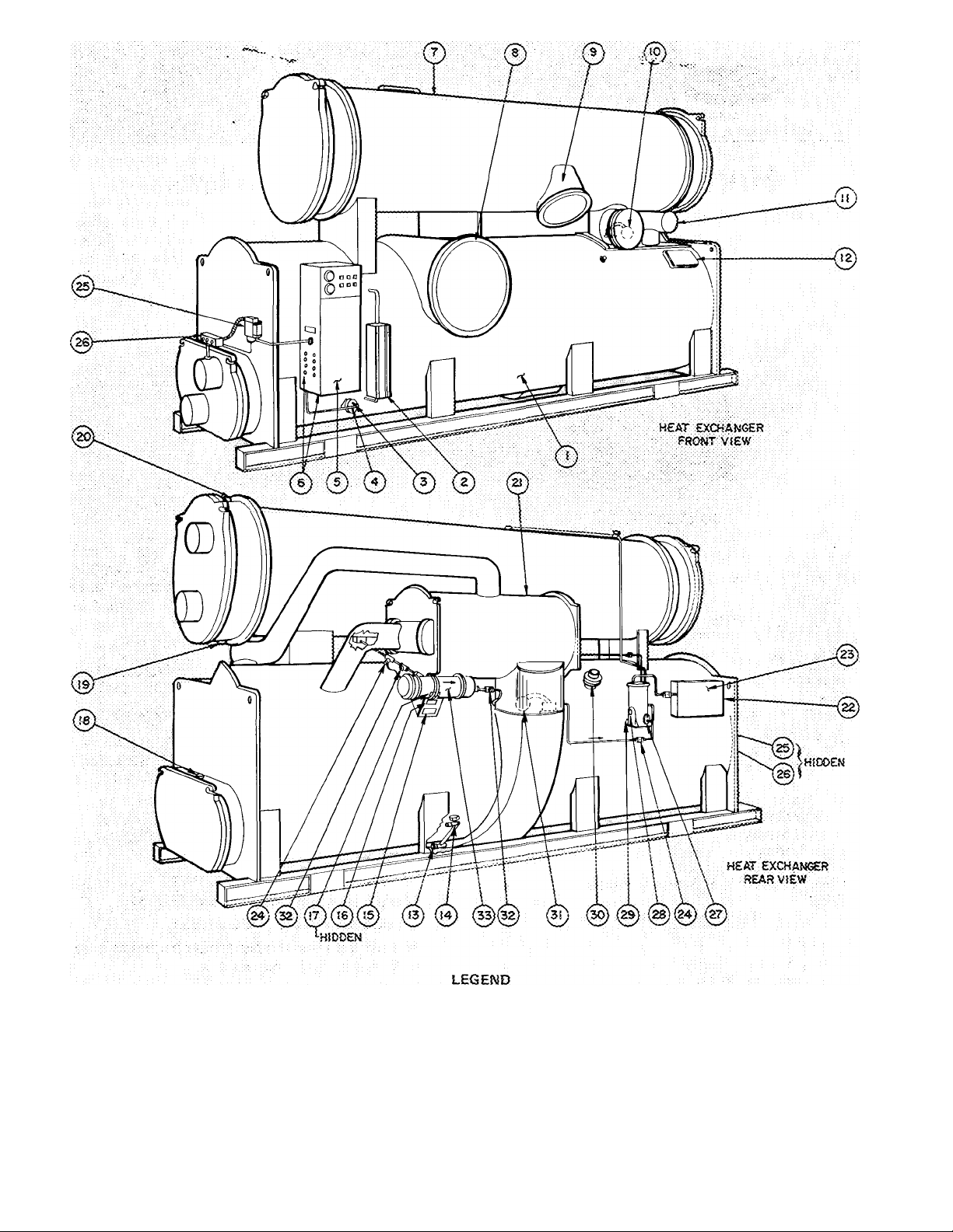
ì
— Cooler
— Cooler Ret:igerant Level Sight Glass
2
— Low Refrigerant Temoerature Sulb
3
— Thermometer Well
4
— Machir.e Control Ceitter
5
(See Rig.:«.) ,
6
~ KnockouwforRieici Wiritts :
— Condenser
7
— Cooler S'.jotion Pipe
S
— Condettser Discharge Ripe
3
—, Condenser Float Valve;
ÎO
— iiconomiser Pipe
n
12 — Cooler-Econorttize: Epuati^iitg Damper
Access Cover
■ 53 - Refrigerant Connection, 1 1/2 NRT
14 — Cooler Charging Valve, 3/4 NPT
15 — AS:Vi£ Nomepiats
16:Machine informative Plate
17 — Safety Code Sticker
IS — Cooler Watsrbcx vent, 3/4 MPT
13 — Condenser W'arerbox Drain, 3/4 MPT
20 — Condenser Waterdox Vent, 3/4 MPT
21 — iiconomizer
22 — Porge Operatirrg Switch
23 24 25 26 27 28 23 30 ~
31 -
32 -
33 ~
Fig. 1 — 19CB Machine Components (R-114 Unit Shown)
P'orge Conderising Chamber
Riiter-Drier Shetoff Valve
Chilled Water Low-Temp Cutout
Chi lied Watsr Terr^p P: obe
Purge Refrigerant Level Sight Giass
Purge Water Level Sight Glass
Purge Water Drain Valve
Rupture Disc Assembly
Economizer Pioat Valve
Moisture Indicator
Pilter-Drier
Page 3
pressure cylinder. Never apply full cylinder
pressure to the pressurizing line. Follow steps 2
thru 5 in proper sequence.
2. Open cooler charging valve fully.
3. Open cylinder regulating valve slowly.
4 Observe cooler or condenser pressure gage and
close cylinder regulating valve when pressure
reaches test pressure listed in Table 1.
Do not exceed test pressure!
5. Close cooler charging valve. Remove copper
tube.
R-11 machines may be pressurized with the
purge pump. Ensure that electrical supply to purge
pump is 120 volts. Then follow Operation 3 on the
purge valve chart.
R-1 14 machines may be pressurized with the
pumpout unit This method is detailed in the
section entitled Pumpout Procedures.
Table 1 — Test Pressures
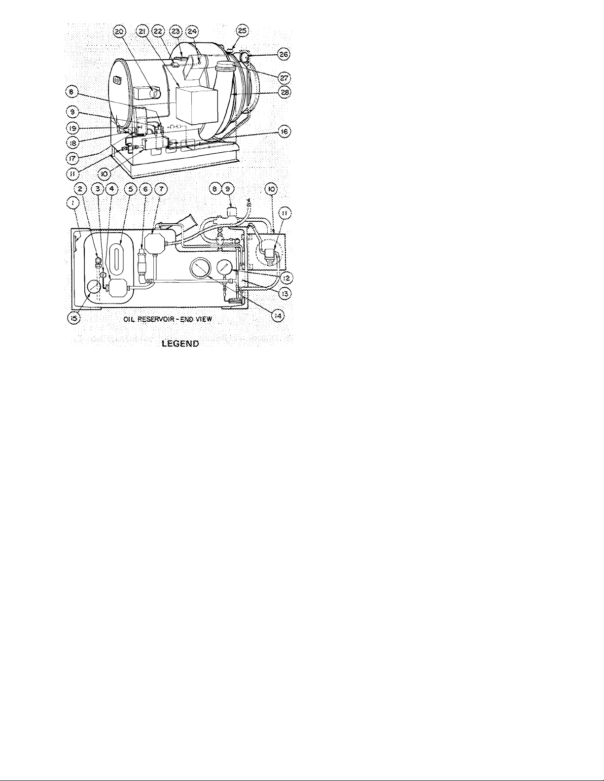
1 Serial Numlser idenritica-
Tior> Piste
2 Oil C^iarairvg Valve
3 Gii Heater Tl>erfr;ost3t
4 Oil Heater ; ern-.inal Sox
5 Oil Reservoir Siijf.t Glass
6 Oil-Pressare Regtila-rioó
Valve. : :
7 Oil Purtiii Temrinal Sox
8 •'!=•■ Solenoid Valve
9 "G" Soteooici Vaive
tO Gii Cooler
Water-Ir, Conr>..Solenoid
Valve and Plue Cook
12 Oli-Pressore Gage
13 OiPPrsssure Oiilerenrial
Switoli
14 Bearing Temperature Gage
15 Oli XemperaTure Gage
Fig. 2 — Compressor (Electronic Capacity Control)
Machine Tightness — If machine leak testing and
16 Oit Cooler Wa‘-:-r-Oor
Gconeotion
17 Oil Pornp Nciirrepiate
18 Gornoressor Nameplate
19 edmpt esser Joriction Sox
20 Economlter inlet
21 Compressor Morof Terminai
Sox (Par side on most ■ :
rncdetsl: r:'.
22 Motor and Stg H i-Temp-
C'-itout iluncticrn Sox ;
23Main Searing inspection Cove'
24 EeonomiKer Darooer Ccn-
r.ection .CR 014 dniy}■ T
25 Guide yiane indicator
{gleotronte ConTrot) : :
26 Hydrau lic V-ane Motcir
27 Oispharoe StuOouT- :
28 DiscP-aige Pipe
dehydration was not completed at installation,
check machine tightness (including pumpout sys
tem) as described below. Dehydration must be
repeated if machine has been idle for several weeks
after initial dehydration.
Check for Large Leaks — Using one of the methods
described below, pressurize the machine to the
level listed in Table 1. Do not exceed test pressure
Listen for large leaks as the pressure builds up. If
test pressure holds for one hour, proceed with
Check for Small Leaks.
All 19CB machines may be pressurized with
cylinders of dry air or nitrogen thni the cooler
charging valve. Dry air or nitrogen charging is
preferable to purge or pumpout charging as it
ensures that moisture will not be introduced into the
machine. To pressurize with nitrogen (or dry air):
1. Connect a copper tube from charging valve to
REFRIGERANT
R-11
R-114
Check for Small Leaks
TEST
PRESSURE
8-10 psig
30 - 35 psig
1. Pull a vacuum equal to 5 in. Hg (12 5 psia) by
using purge pump Operation 2 (R-11
machines), pumpout unit (R-114 machines) or
by applying a vacuum pump at the cooler
charging valve.
2. Charge approximately 25 pounds of the proper
refrigerant thru the cooler cliarging valve.
3
Pressurize machine to test pressure (Table 1)
using purge pump, pumpout unit, dry air or
nitrogen. Do not exceed test pressure
Test all joints, valves, fittings etc. with a halide
4.
or electronic leak detector.
Check Leakage Rate
1 Install a mercury manometer (absolute pressure
type) on a tee at the cooler charging valve.
2.
Pull 25 in. of vacuum on the machine.
Let machine stand with this vacuum for at least
3
8 hours
If leakage rate is less than 0.1 in. Hg in 24 hours
4.
(0.033 in. Hg in 8 hrs), machine is sufficiently
tight. Perform Machine Dehydration.
If leakage rate exceeds 0.1 in. Hg per 24 hours,
5.
repeat Check for Small Leaks, repair leaks and
repeat this Leakage Rate check.
Remove or valve off manometer before re
6.
peating any pressure test.
Machine Dehydration
W.^iRNlNG: Do not attempt to start compres
sor, oil pump or purge motor even fox a
rotation check, nor app.ly test voltage of any
kind while machine is under dehydration
vacuum- Motor insuiation breakdown and
serious damage tnav result.
Page 4
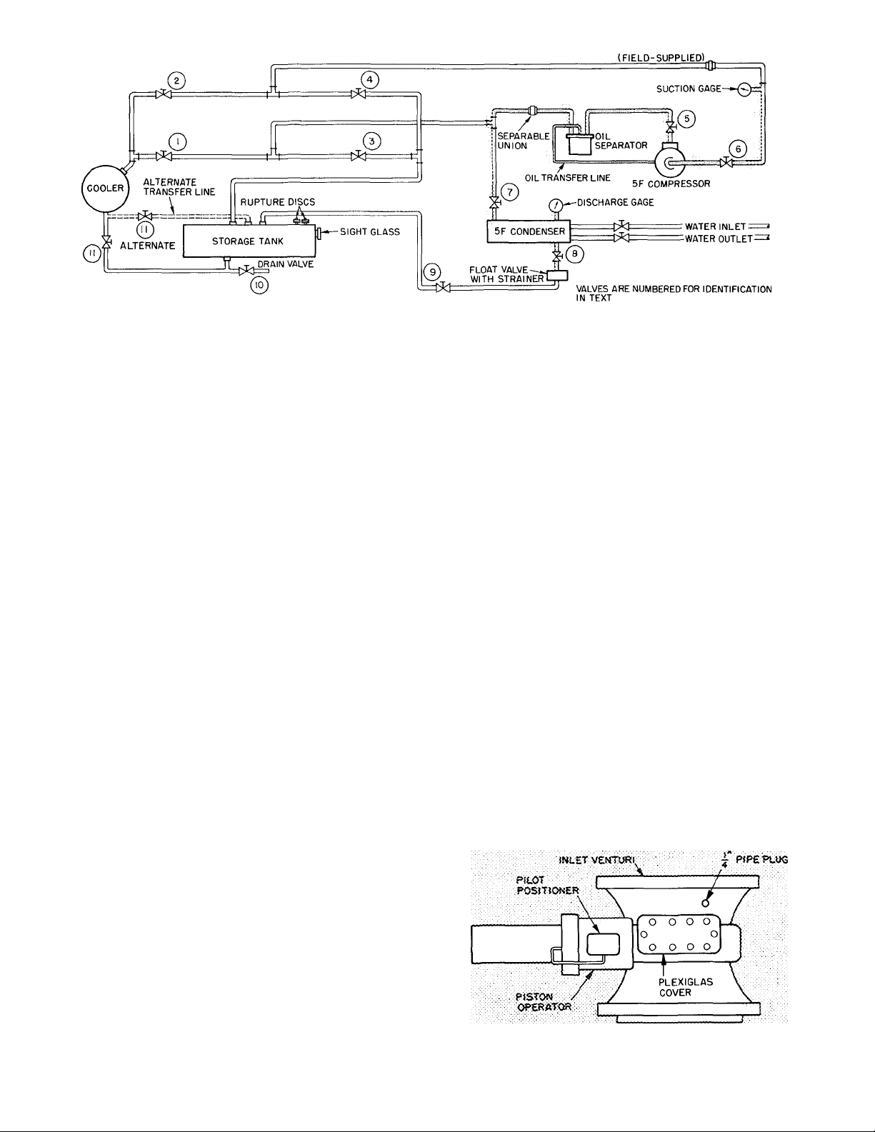
Fig. 3 — Pumpout System Schematic (R-114 Units)
SEPARABLE UNION
PIPING BY CARRIER
FIELD PIPING
1. Connect dehydration pump to cooler charging
valve.
2. Ensure that all valves on purge assembly are
closed; valves on filter-drier system open.
3. Install mercury manometer (absolute pressure
type) at charging valve.
4. Operate pump until manometer reads 0.20 in.
Hg absolute. Continue to operate pump for 2
more hours.
5. Close cooler charging valve; stop pump; record
manometer reading.
6. Wait 2 hours and read manometer again. If ab
solute pressure reading has not increased, dehy
dration is complete. If absolute pressure has
increased, repeat steps 4, 5 and 6.
7. If vacuum fails to hold after several dehy
dration attempts, check for machine leak by
repeating the (?heck for Small Leaks.
Pumpout Procedures (R-114 Units)
MACHINE EVACUATION (No refrigerant in
system)
1. Set purge valves per Operation 5 on purge valve
operation plate.
2. Jumper low-pressure cutout on pumpout
compressor.
3. Close valves 1, 3, 7 and 10.
4. Open valves 2, 4, 5, 6, 8, 9 and 11
5. Disconnect separable union between pumpout
condenser and oil separator.
6. Run pumpout compressor until desired
machine vacuum is reached.
7. Close valve 5 and reassemble union.
8. Stop compressor.
9. Remove jumper.
PRESSURIZING THE MACHINE (No refrigerant
in system)
1. Set purge valves per Operation 4 on purge valve
operation plate.
2. Close valves 2, 4 and 10.
3. Open valves 1, 3, 5, 6, 7, 8, 9 and 1 1.
4. Disconnect separable union in pumpout com
pressor suction Hne.
5.
Operate pumpout compressor until desired
pressure is reached. Do not exceed test pressure
listed in Table 1.
6. Shut off pumpout compressor
7. Reassemble union.
8. Return purge valves to “Normal-Auto” condi
tion when pressurizing is completed.
Oil Charge — Use oil shipped with machine. This
oil conforms to Carrier’s oil specifications for
hermetic centrifugal compressors.
Charge oil thru the oil reservoir charging valve.
Machine vacuum will draw the oil from the
container. Add oil until it reaches the middle of
the oil sight glass. After charging, close valve
completely to prevent air from entering machine.
R-114 machines containing refrigerant will require
a small hand pump for oil charging.
On pneumatic machines, add oil to the vane seal
chamber thru pipe plug opening (see Fig. 4) until
level reaches bottom of rack and gear as seen thru
Plexiglas cover.
Oil Heater — Check for 1 20 volt supply. Energize
oil heater to minimize oil-refrigerant absorption. A
light indicates when the heater is energized. The oil
heater thermostat is set to maintain a temperature
of 140 F ± 3 F at shutdown. Adjust if required.
Fig. 4 — Pneumatic Vane Shaft Seal Chamber
Page 5

r.
Refrigerant Charge
1. Install a charging valve in the 3/4-in. drum
opening as shown in Fig. 5.
Fig. 5 — Drum Charging Valve
Chilled water should enter the lower nozzle of
the cooler and leave at the upper nozzle. Chilled
water temperature probe should be installed in
leaving chilled water hue.
Condenser water should enter the upper con
denser nozzle and leave at the lower.
Insure that pipes are vented and properly
suspended, with no stress on nozzles or on water
box covers.
Check to see that water flow agrees with design
flow. Pressure drop measurements across cooler
and condenser or across the pumps will indicate
approximate flow rate.
Oil cooler water must be clean, with 85 F
maximum temperature and 200 psi maximum inlet
pressure. Refer to tag attached to the inlet line for
pressure drop and velocity limits.
Field Wiring
Connect a short length of plastic hose or copper
tubing from drum valve to cooler charging
valve.
Circulate chilled water during the charging
3.
process.
At a pressure less than that indicated in Table
4.
2, liquid refrigerant will flash into gas and may
cause tube freeze-up. Keep refrigerant drum
upright and admit refrigerant as a gas until
cooler pressure is greater (smaller value of in. of
mercury vacuum) than that listed in Table 2.
Table 2 — Pressures Corresponding to 32 F
Saturation Temperature
REFRIGERANT
R-11
R-114
PRESSURE - INCHES
OF MERCURY VACUUM
18 05
3 85
5 The refrigerant supplied with the machine is in
excess of the amount required for initial charg
ing. Charge the amount shown in Table 3, less
200 pounds
6. After the machine has been started, it may be
necessary to adjust the charge for optimum
machine performance. For this adjustment, see
Trimming Refrigerant Charge.
Table 3 — Refrigerant Shipping Charges
MACHINE SIZE
Model Heat Exch
No. ^ Combn*
19CB1200
19CB1300 19CB33-36 R-11
19CB1400
19CB1500
19CB1600
19CB1800
19CB2000
*First 6 digits of 1 0-digit Machine Model code
Inspect Piping
19CB33-36
19CB43-46 R-11
19CB53-56
19CB64-66 R-11
19CB77-78 R-114
19CB87-88 R-114
REFRIG
R-11 3200
R-11 3750
SHIPPING
CHARGE
3200
3750
4000
5400
5400
Refer to piping diagrams provided in Job Data
and inspect piping to cooler, condenser and oil
cooler.
WARNING: Do not attempt to check high
voltage supply without proper equipment.
Serious personal injury' cajr result.
Refer to Job Data wiring diagrams and check
field wiring as follows:
1. Connect voltmeter across incoming power wires
to compressor motor starter. Compare the
reading with voltage ratings on compressor and
starter nameplates.
2. Check that amperage rating on starter name
plate matches full load amperage rating on
compressor motor nameplate.
3. Ensure that voltage to oil pump starter agrees
with oil pump nameplate value.
4. Ensure that pumpout compressor voltage ^sup
ply agrees with motor nameplate.
5. Check that electrical supply to purge pump
(R-11) is 120 volts.
6. Test compressor motor and motor power lead
insulation resistance with a 500 volt insulation
tester such as a megohmmeter.
a Open starter nmin disconnect switch.
b. With tester connected to the motor side of
the starter contactor in the starter, take
60-second and 10-second megohm readings
as follows’
Six lead motor — Tie all 6 terminals together
and test between terminal group and ground.
Next, tie terminals in pairs, 1 and 4, 2 and 5,
3 and 6. Test between each pair while
grounding the third pair.
Three lead motor — Tie terminals 1,2 and 3
together. Test between terminal group and
ground.
c. Divide the 60-second resistance reading by
the 10-second reading. This ratio, or polar
ization index, must be 1.15:1 or higher.
Both the 10-second and 60-second reading
must be at least 5.0 megohms. If the
readings are unsatisfactory, repeat the test
at the motor terminals with power leads
disconnected. Satisfactory readings in this
second test indicate that the fault is in the
motor leads.
Page 6

Check Starter — Before starting the 19CB machine,
open the main disconnect and check starter.
1. Remove contactor arc chutes. Be sure con
tactors move freely and that shipping string has
been removed. Replaee arc chutes.
2. Check contactors for dirt and rust. Clean
contact magnet surfaces lightly with sandpaper.
Do not sandpaper or file silverplated contacts.
Apply a very thin coat of petroleum jelly to
magnet surfaces and then wipe it off. If starter
has been in a dusty atmosphere, vacuum clean
the cabinet and wipe with hnt-free cloth.
3. Remove fluid cups from magnetic overload
relays. Add dashpot oil to cups per instructions
on relay nameplate. Oil is slripped in small vials
usually attached to starter frame near the
relays. Use only dashpot oil supplied with
starter. Do not substitute. Overload relays are
factory set for 108% of motor full load
amperage. Resetting is not normally required,
nor is it recommended except by a qualified
electrical shop.
4. Check transfer timer for proper setting. On
Star-Delta starter, timers have adjustable range
of 10 seconds to 3 minutes and are factory set
for 1 minute. Auto.-Transformer timers have
adjustable range of 1 to 60 seconds and are
factory set at 30 seconds.
5. With main disconnect open, manually open and
close the main control relay (ICR) to be sure it
operates freely.
Check Operation of Safety Controls — As the
following checks are made, control panel lights
should appear as indicated in the diagrams.
OFF ON
□
1. Open main disconnect (all
power off to starter and
controls). Disconnect
main motor leads in
starter.
2. Provide control circuit
power from separate
115-volt source.
3. Press ON-STOP button
(light goes on). If
n
STOP
POUVER SAFETY LOAD
□
STOP
POWER SAFETY LOAD
■ □ n
STOP
ON
n
CIRCUIT RECYCLE
ON
■
CIRCUIT RECYCLE
ON
□ □
START OIL
□ □
□ □ n
PROGRAM
□
START OIL
PROGRAM
START OIL
PUMP
n
TIMER
□
PUMP
TIMER
PUMP
SAFETY CIRCUIT light
does not go on, check
resets on condenser high-
■ ■ ■ n
SAFETY LOAD
POWER
CIRCUIT RECYCLE
PROGRAM
TIMER
pressure safety, low-refrigerant temperature
safety, bearing and motor Ihgh-temperature
circuit breakers and compressor overloads in
starter. Check 3-amp fuse in control center.
If SAFETY CIRCUIT light goes on but
LOAD RECYCLE light stays off, check the
chilled water recycle switch (auto-reset).
If both lights go on, manually trip and reset
motor and bearing high-temperature circuit
breakers, compressor motor overloads in
starter, and low-refrigerant temperature cutout
to be sure they cut off the safety light.
Tripping the chilled water recycle switch will
cut off the LOAD RECYCLE light only.
ELECTRONIC CONTROL PNEUMATIC CONTROL
Fig. 6 — Control Center Components
4. Press ON-STOP button
(light goes out). Remove
and tag gray striped wire
from control center
□ □
ON
START OIL
STOP
■ □ □ n
POWER SAFETY LOAD
CIRCUIT'RECYCLE
terminal
5. Start chilled water and
condenser water pumps.
Press ON-STOP button
(light goes on).
6. Press OIL PUMP button
for several seconds. Pump
■
STOP
□
ON
START
■
□ □ n
POWER SAFETY LOAD
CIRCUIT RECYCLE
■ □
ON
START
STOP
should raise oil pressure
■
16 - 18 psi above refrig
erant pressure at machine
POWER
■ ■ n
SAFETY LOAD
CIRCUIT RECYCLE
shutdown condition. SAFETY CIRCUIT and
LOAD RECYCLE lights should go on.
7. Release OIL PUMP
button. SAFETY CIR
CUIT light and LOAD
RECYCLE light should go
out.
■ □ n
ON
START OIL
STOP
□ □
■
SAFETY LOAD
POWER
CIRCUIT RECYCLE
□
PUMP
PROGRAM
TIMER
□
PUMP
PROGRAM
TIMER
■
PUMP
PROGRAM
TIMER
PUMP
n
PROGRAM
TIMER
OIL
OIL
Page 7

With OIL PUMP button
depressed, alternately stop
and restart chilled water
and condenser water
pumps. SAFETY
■ □ ■
ON
START OIL
STOP
■
POWER
□ □
SAFETY LOAD
CIRCUIT RECYCLE
n
PROGRAM
TIMER
PUMP
CIRCUIT and LOAD RECYCLE lights should
go out as each pump stops. (Continuous
operation of oil pump is unnecessary during
these checks.)
9. Shut off water pumps. Release OIL PUMP button.
□ □ □
ON START OIL
STOP PUMP
Press ON-STOP button
(light goes out). Replace
tagged wire on terminal
(L),
10. Press ON-STOP button
(light goes on).
11. Press machine START
button (motor leads
disconnected).
■ □ □ □
POWER SAFETY LOAO PROGRAM
CIRCUIT RECYCLE TIMER
■ □ □
ON START OIL
STOP PUMP
■ ■ ■ □
POWER SAFETY LOAD PROGRAM
CIRCUIT RECYCLE TIMER
■ ■ □
ON
■
POWER
START
■ ■
SAFETY LOAD
CIRCUIT RECYCLE
■
PROGRAM
TIMER
STOP
OIL
PUMP
Oil pump starts within 30
seconds.
Compressor motor start
contacts will close 30
seconds later. Starter will
transfer to its run condi
tion 30 to 60 seconds
■ ■ ■
ON
■
START OIL
■ ■
CIRCUIT RECYCLE
PUMP
n
PROGRAM
TIMER
STOP
POWER SAFETY LOAD
after starter is energized.
12. Open oil pump main dis
connect. Starter must de
energize. OIL PUMP light
will remain on for approx
imately 5 minutes.
OIL PUMP light goes out.
13. Close oil pump dis
connect. In approximately
10 minutes the program
timer will complete the
antirecycle portion of its
■
STOP
POWER
□ ■
ON
START
■
□ □ ■
SAFETY LOAO
CIRCUIT RECYCLE
■
STOP
POWER SAFETY LOAO
■
STOP
POWER
□
ON
START
■ □ □ ■
CIRCUIT RECYCLE
□ □
ON
START OIL
■
■ ■ n
SAFETY LOAO
CIRCUIT RECYCLE
OIL
PUNIP
PROGRAM
TIMER
n
OIL
PUMP
PROGRAM
TIMER
PUMP
PROGRAM
TIMER
cycle and machine is
ready to restart. (Total
recycle time — 15
minutes.)
14. Remove all power. Reconnect motor leads.
Restore power.
Purge — Place the purge operating valves (Fig. 1) in
“Normal-Automatic” position as indicated in Oper
ation no. 1 on the purge valve operation plate.
Operate the purge momentarily by placing the
purge switch in “Manual” position; then place
purge switch in “Auto.” position.
Air Supply (Pneumatic Controls Only) — Check 25
psi air supply to pneumatic temperature controller
and pilot positioner.
START-UP
Before Starting Machine — Be sure that-
Power switch is on to circuit breakers, water pumps,
tower fan and control circuit.
Cooling tower water is at proper level.
Oil is visible in reservoir sight glass.
Oil reservoir temperature is 140 F or warmer.
Oil cooler plug cock is cracked open and any other
valve in the oil cooler line is fully open.
Refrigerant is at selected design level.
Valves in cooler and condenser water circuits are
open Do not permit water above 100 F to flow thru
cooler
Filter-drier shutoff valves (Item 24, Fig. 1) are open.
Air supply for pneumatic controls is adequate
COMPRESSOR ROTATION - Electronic Control:
Set capacity control switch on “Hold.”
Pneumatic Capacity Control: Turn off supply air
to chilled water thermostat and vane positioner.
Press machine ON-STOP and START buttons.
As soon as motor begins to turn, press machine
ON-STOP button. Check motor rotation thru sight
glass on motor end bell. Motor rotation must be
counterclockwise as viewed thru sight glass.
COMPRESSOR OPERATION — Press machine
ON-STOP and START buttons and let compressor
come up to speed. Press machine ON-STOP button
and listen for any unusual sounds from compressor
as it coasts to a stop.
The program timer prevents rapid recycling and
allows compressor restart 15 minutes after stop.
Checking Safety Control Settings
■While performiiig these checks, carefully moni
tor cMlied -vt'ateT temperature to prevent
freeze>-up. Protection by safety controls cannot
be assumed until all settings have been con
firmed as follows:
Open main disconnect (all power off to starter
and controls).
Electronic Control: Set capacity control switch on
“Hold.”
Pneumatic Control: Ensure that pilot positioner
operates as described in Setting Operating
Controls-Pneumatic. Then set percent load
Page 8

knob on demand limit control at 100% and turn
calibration screw fully clockwise.
Place a clamp-on ammeter on one of the 3
starter leads. Be sure ammeter scale is set so that
compressor full load amperage will register be
tween midway and just under the top of the scale.
Install jumpers between ^ and [^, and
between and 11
Close disconnects, start
Table 4 — Setting Safety Controls
compressor and check oil pressure and temperature
(Fig. 2). With compressor running, operate the
guide vanes with capacity control switch or pneu
matic thermostat. Do not exceed 100% full load
amps.
1. Check controls 1 and 2 as indicated in Table 4.
2. Stop machine, open disconnects, remove
jumpers and check controls 3, 4 and 5 as
indicated.
SAFETY OR CONTROL DEVICE
1. Chilled Water Low-Temperature Cutout and Recycle Switch
(Fig. 1)
'TEMPERATURE AD.IUSTMENl
^ O,
DIFFERENTIAL ADJUSTMENT
JZ, —’ ''Bi*
Set this switch to break at approximately 5 F below design
chilled water temperature, or at 36 F whichever is higher
Set the differential at 10 ± 1 F so that when the machine shuts
down automatically at approximately 5 F below the design
chilled water temperature it will restart at approximately 5 F
above the design water temperature.
This control must break ahead of the refrigerant low-
temperature cutout switch or the machine will not recycle
automatically
SAFETY OR CONTROL DEVICE
STOP MACHINE, REMOVE JUMPERS AND PEREORM RE
MAINING CHECKS.
3. Condenser High-Pressure Cutout (Fig. 6)
CUTOUT ADJUSTMENT .f.'
COVER
RESET
BUTTON
CUTOUT SCALE
The condenser high-pressute cutout is factory set to shut the
machine down when condenser pressure reaches setting listed.
Isolate the switch and check setting with a metered supply of air
JiEFRlG
114
SETTING
ii
15 psig
45 psig
2. Refrigerant Low-Temperature Cutout (Fig. 6)
CUTOUT
ADJUSTMENT
Set refrigerant low-temperature cutout at 33 F or one degree below
design refrigerant temperature, whichever is lower, while checking
temperature at thermowell near control center
4. Oil Heater Thermostat (Fig. 2)
Set the oil heater thermostat to maintain a minimum oil reservoir
temperature of 140 F at shutdown.
Page 9

Table 4 — Setting Safety Controls (contd)
SAFETY OR CONTROL DEVICE
5. Low Oil Pressure Cutout (Fig, 2)
RESERVOIR
PRESSURE-:^,
RANGE ^
DIAL ADJUSTMENT,
REMOVE METAL
COVER
DIFFERENTIAL-
OIL
PRESSURE
Low oil differential pressure switch is factory set to open at 5 5 ± 1
psi and close at 12 5 ± 1 psi differential pressure Operate oil pump
manually Remove cap and gasket from regulating valve and loosen
locknut Turn adjusting screw counterclockwise to lower oil
pressure to 5 psi differential If safety does not trip, turn range dial
clockwise until cutout occurs
6. Oil-Pressure Regulating Valve (Item 6, Fig 2).
REFRIG
^ R- Vl
R-114
^Settings given are above
reservoir pressure
SEALING
GASKET'
Remove cap and washer and loosen locknut Turn adjusting screw
clockwise to raise oil pressure
SETTING*
1 5 psid
.
15-20 psid
SAFETY OR CONTROL DEVICE
7. Vane Speed Valve (Electronic Machine Only)
Angle valve is located between oil line to main bearing and "F" and
"G" solenoid valves (Items 8 and 9, Fig 2) Set valve at full open
position
8. Chilled Water Flow Switch
Field supplied and ir-rstalled Follow switch manufacturer's instruc
tions for adjustment and maintenance
9. Main Bearing Oil Temperature (Item 14, Fig. 2).
During machine operation, gage should read 145-160 F Adjust
water flow thnr oil cooler with plug cock (item 11, Fig. 2) Do not
exceed 7 gpm or pressure drop of 5 psi Do not exceed 200 psig
working pressure
10. Dual Pressurestat for R-114 Pump-Down Compressor
COVER
LOW-PRESSURE
SWITCH
COMPRESSOR
CONNECTIONS'
High-pressure switch to open on rise at 45 0 psig Low-pressure
switch to open on fall at 2 0 in Hg vacuum
Set high-pressure switch by operating compressor and throttling
pump-down condenser water while watching pressure gage
Set low-pressure switch by operating compressor and gradually
shutting suction valve while watching pressure gage
CUTOUT AND
CUT-IN PRESSURE
ADJUSTMENT
HIGH-
PRESSURE
SWITCH
CUT-IN
PRESSURE
'ADJUSTMENT ONLY
CUTOUT PRESSURE
ADJUSTMENT ONLY
Setting Operating Controls — Electronic
MOTOR CURRENT CATIBRATION (Electronic
Capacity Control)
1. Establish a steady motor current value for this
calibration. Open guide vanes manually
(capacity control to “Inc”) until full load
current is reached. Motor current calibration
(Fig. 7) may need to be turned counterclock
wise to permit vanes to open further. Do not
exceed 105% of nameplate full load amperes.
If system load is sufficient to maintain full
load current for a period of time, calibrate at
this condition. With small loads, pull down to
and maintain design leaving chilled water
temperature (capacity control at “Hold”) and
calibrate at this condition.
2. Measure motor current at selected condition.
Determine its percentage of full load motor
current.
3. Use this percentage figure to set the electrical
demand adjustment (Fig. 7) per the following
table:
Percent of Full
Load Motor Current
105
85 or above
65 to 84
45 to 64
below 45
Electrical Demand
Adjustment Setting
100%
80%
60%
40%
Control cannot be
calibrated
4. Turn the motor current cahbration adjustment
fully clockwise. The guide vanes will close part
way.
5. Turn the thermostat adjustment (Fig. 7) to
“Cooler” (fully counterclockwise).
6. Set capacity control at “Inc
7
Slowly turn the motor current calibration
position.
counterclockwise. Allow the guide vanes to
open until motor current reaches 5% above the
electrical demand setting.
NOTE: There is a time lag of several seconds
due to feedback capacitance in the motor
current circuit. When the motor current cali
bration setting is adjusted, allow for this time
lag.
Page 10

• ^^>4-iXwCr.- ••VJ 'ava>
; «O*«®
Fig. 7 — Capacity Control Module
(Electronic Control)
The electrical demand adjustment permits the
operator to set the maximum current drawn by the
motor and thus minimize the electrical demand
rate during off-season operation.
CHILLED WATER CALIBRATION (Electronic
Controls)
1. Turn throttle range adjustment (Fig. 7) fully
clockwise.
2. Turn chilled water thermostat until design
chilled water temperature is maintained. Mark
thermostat at this position. If capacity control
vanes hunt, turn throttle range adjustment
counterclockwise in small increments until
hunting ceases. Chilled water thermostat may
require resetting.
Setting Operating Controls — Pneumatic Capacity Control
PILOT POSITIONER
Check the foregoing motor current calibrations
with machine under “Auto.” control as
follows'
Close vanes manually (capacity control to
a.
“Dec”).
Turn capacity control to “Auto.” Vanes
b.
should stop opening at electrical demand
setting.
control was calibrated at less than 100%
9. If
load, turn electrical demand adjustment setting
to 100%. Control is now automatically cali
brated for 100% full load current.
10. If control cannot be calibrated with above
procedure, check voltage signal from signal
resistor in starter. At 100% full load current,
voltage between terminals 23 and 24 inside
control center must be 0.5 ±0.1 volts. If not
in this range, check sizing of resistor in starter.
Both excess motor current and chilled water
temperatures below the thermostat set point (Fig.
7) will override the capacity control setting. If the
capacity control knob is in the “Inc” position, the
guide vanes will stop opening. With the knob in any
of the other positions, the vanes will close as needed.
The motor current hmiting circuit operates in
2 steps.
At 100% full load motor current, the vanes
will stop opening further. If the motor current
should increase to 105% due to some change in
load conditions, the vanes will close until the
motor current is reduced to about 102%.
If the motor current is reduced to 98% or
below, control again operates in response to chilled
water temperature.
ITEM DESCRIPTION
1 MAIN AIR CONNECTION (25 PSIG)
2 STARTING POINT ADJUSTMENT NUT
3 LEVER ARM
4 FOLLOWER SPRING
5 PILOT AIR CONNECTION
(FROM CONTROL CENTER)
Preparation:
a. Place jumper between field wiring terminal
and load limiting module terminal*^.
b. Open 25 lb air supply valve.
c. Remove cover from pilot positioner.
Calibration:
Rotate dial on chilled water thermostat to vary
pilot pressure. Observe pressure gage in pilot
supply line near pilot positioner and adjust starting
point nut (2) until piston operator begins to move
at 5 psi pilot pressure. Place follower spring (4) in
proper hole in level arm so that piston operator
opens 100% at 15 psi pilot pressure.
Completion:
Remove jumper from terminals and
Replace cover.
10
Page 11

ELECTRO-PNEUMATIC RELAY
LOCKNUTS SENSITIVITY SCREW
^SET POINT SCREW
COVER
CONTROL AIR
(OUTPUT)
This control is factory calibrated to provide a
linear output signal of 3 psi at 6 volts d-c to 18 psi
at 15 volts d-c. Field recaHbration should not be
necessary.
If calibration is required:
1. Establish 15 volt d-c input with 25 psi supply air.
2. Turn sensitivity screw to obtain 18 psi or higher
output.
3. Adjust setpoint screw, if required, to set output
at \ 8 ±V4 psi.
4. Reduce input to 6 volts. Output should be 3 ±
V4 psi. If low, turn sensitivity screw carefully
clockwise. If high, turn screw counterclockwise.
5. Recheck output at 15 volts. Repeat steps 3 and
4 if necessary.
DEMAND LIMIT CONTROL
CALIBRATION
ADJUSTMENT
COVER
1. Set percent load dial at 100%.
2. Set band width dial at 3.
3. Turn the cahbration adjustment screw fully
clockwise.
4. Run machine at 100% FLA by adjusting dial on
chilled water thermostat.
5. Turn calibration adjustment screw counter
clockwise until guide vanes just begin to close.
6. If hunting occurs, increase bandwidth and re
peat steps 4 and 5.
7. If control cannot be calibrated with above
procedure, check voltage signal from resistor in
starter. At 100% full load, voltage between
termmals 23 and 24 inside control center must
be 3.0 ± 0.1 volts. If not in this range, check siz
ing of resistor in starter.
CHILLED WATER THERMOSTAT (Pneumatic)
HIDDEN
ITEM
1
2
3
4
5
6
7
SET POINT ADJUSTING SCREW
THERMOSTAT DIAL
SENSITIVITY SLIDER
SUPPLY AIR PRESSURE GAGE
SUPPLY AIR CONNECTIONS
CONTROL AIR PRESSURE GAGE
CONTROL AIR CONNECTIONS
DESCRIPTION
Preparation:
1. Ensure 25 psi supply air to thermostat.
2. Loosen Allen setscrew in sensitivity slider and
move slider halfway between midpoint and DA.
Retighten screw.
Calibration:
1. Turn thermostat dial until control air registers
15 psi.
2. Operate machine to reach design chilled water
temperature at design load. Maintain 15 psi
control air during pulldown by adjusting ther
mostat dial as required.
3. On reaching design chilled water temperature,
turn dial until control air pressure holds
machine at design conditions.
4. Hold set-point adjusting screw stationary within
the dial post and set the thermostat dial at de
sign chilled water temperature.
Completion:
If vane hunting occurs, move sensitivity slider
away from DA. Throttle range may be narrowed or
widened by moving slider between the limits of 0.1
psi/F at midpoint to 5 psi/F at DA.
11
Page 12

FINAL MACHINE ADJUSTMENT
Trimming Refrigerant Charge — After the macliine
has been placed in operation, it may be necessary
to adjust the refrigerant charge to obtain optimum
machine performance.
When machine full load is available, using the
extra 200 pounds of refrigerant, add refrigerant
slowly until the difference between the leaving
chilled water temperature and the cooler tempera
ture reaches design conditions or becomes a
minimum. Shut the machine down and allow
refrigerant to drain to the cooler, mark the level
indicator and maintain that shutdown refrigerant
level.
INSTRUCTING THE CUSTOMER OPERATOR
Be sure the operator carefully reads and under
stands the I9CB Operating and Maintenance
Instructions.
Point out the following machine components,
explain their function and that of the system in
which they are used.
1. Compressor—Motor Assembly
a. Guide Vanes, Vane Positioner
b. Refrigerant-Cooled Motor
2. Cooler-Condenser-Economizer
a. Float Chamber, Sight Glasses
b. Thermowells
c. Rupture Disc
d. Refrigerant Charging Valve
3. Purge System
a. Importance of proper operation
b. Valves and System Operation
c. Sight Glasses, Gage
5. Lubrication System
a. Oil Pump, Cooler, Filter
b. Solenoid Valve, Plug Cock
c. Heater, Thermostat, Temperature Gage
d. Pressure Regulating Valve
e. Oil Level, Temperature
6. Control System
a. Manual Switches (ON-STOP, START, OIL-
PUMP)
b. Gages and Lights
c. Safety Controls
d. Operating Controls
e. Auxiliary and Special Controls
7. Auxiliary Equipment
a. Starter(s)
b. Pumps
c. Cooling Tower
d. Pumpout System (where applicable)
Describe Refrigeration Cycle
Review Maintenance
1. Scheduled
2 Extended Shutdown
3 Importance of Log Sheet
4 Importance of Water Treatment
Check Operator Knowledge
1. Start-Stop Procedure
2 Safety and Operating Controls
Discuss Carrier Service
1. Availability
2. Method of Ordering Parts
Review Operating and Maintenance Instructions
4. Filter-Drier System
a. Cartridge Removal
b Moisture Indicator Check
c. Shutoff Valve Function
For replacement items use Carrier Specified Parts. k
Manufacturer reserves the right to discontinue, or change at any time, specifications or designs without notice and without incurring obligations.
Carrier Air Conditioning Company • Syracuse, New York
Tab 15 Foim 19CB-2SS Supeisedes 19CBUSS
Printed in U S A
10^73
Codes MA and ML
Catalog No 531-942
 Loading...