

Page 1
Electronic Control
1995 Room Air Conditioner
Start-Up and Service Instructions
CONTENTS
Page
SAFETY REMINDERS 1
START-UP 1
SERVICE 1-3
General Notes 1
Compressor Replacement 3
PREVENTIVE MAINTENANCE 3
General 3
System Cleaning/Flushing 3
DISASSEMBLY INFORMATION 3 11
Filter Removal 4
Front Grille Removal 4
Chassis Removal 4
Control Box Removal 5
Electronic Control Board Removal 6
Capacitor Removal 7
Air Sweep Motor Removal 7
Air-Handling System Removal 7
Evaporator and Condenser Coils Removal 8
Exhaust Door Removal 8
Indoor Blower Wheel Adjustment
or Removal 9
Propeller Fan Adjustment or Removal 10
Fan Motor Removal 10
Compressor Removal 11
Strainer Removal and Replacement 11
SERVICE POINTS 11
TROUBLESHOOTING 12
SAFETY REMINDERS
1 Carry a fire extinguisher in your truck Keep it within
reach when using a torch Check fire extinguisher peri
odically to be sure it is fully loaded and functional
2 Know how to handle oxyacetylene equipment safely Lock
the equipment in an upright position in the truck and at
the job site
3 Use dry nitrogen or carbon dioxide to pressurize the sys
tem for leak checking Always use a good regulator Be
careful not to exceed 150 psig test pressure in the her
metic compressor
4 Wear safety goggles and gloves when recovering refrig
erant from a system
5 Attend shop safety meetings
START-UP
Refer to opeiating instructions in Owner’s Guide pro
vided with room air conditioner
SERVICE
General Notes — These Start-Up and Seivice Instruc
tions aie provided to assist the trained and qualified service
technician in lepairing or replacing components of Carrier
electronically conti oiled (EC) Room Air Conditionei Dis
assembly photos are included for the unit Unit physical
data is found in Tables 1-9
IMPORTANT Repairing and servicing air condition
ers can be hazardous for untrained individuals The
instructions printed in this publication are for propeily trained and qualified Carrier seivice technicians
only
A WARNING
Before working on any air conditioner, be sure to first
disconnect all electric power to the unit to avoid the
possibility of electrical shock and personal injury
Before disconnecting, discharge capacitors by shorting
capacitors across terminals
Shield coils with cardboard to protect hands against in
jury from sharp metal edges when removing compressor and
other components
When disassembling wiring, use numbered stickers to iden
tify wire leads and terminals This aids in quick, accuiate
reassembly
Check clearances around scroll and housing before in
stalling fans Before securing fan(s) fasteners, rotate fan by
hand to ensure ample clearance
Refer to Carrier Standard Service Techniques, Chap
ters 1 and 2, for information on checking motors, removing
refrigerant, adding oil, and evacuating, dehydrating, and charg
ing system Pay particular attention to all safety warnings
for these procedures
NOTE In Carrier Standard Service Techniques, refrigerant
removal must always include recovering the refrigerant, not
allowing it to escape to the atmosphere
Book|1 14 PC 131 Catalog No 537-323 Printed in USA Form73XC-1SS Pg 1 1-95 Replaces: New
Tab 8a 10a
Manutecturer reserves the right to discontinue, or change at any time, specifications or designs without notice and without incurring obligations
Page 2
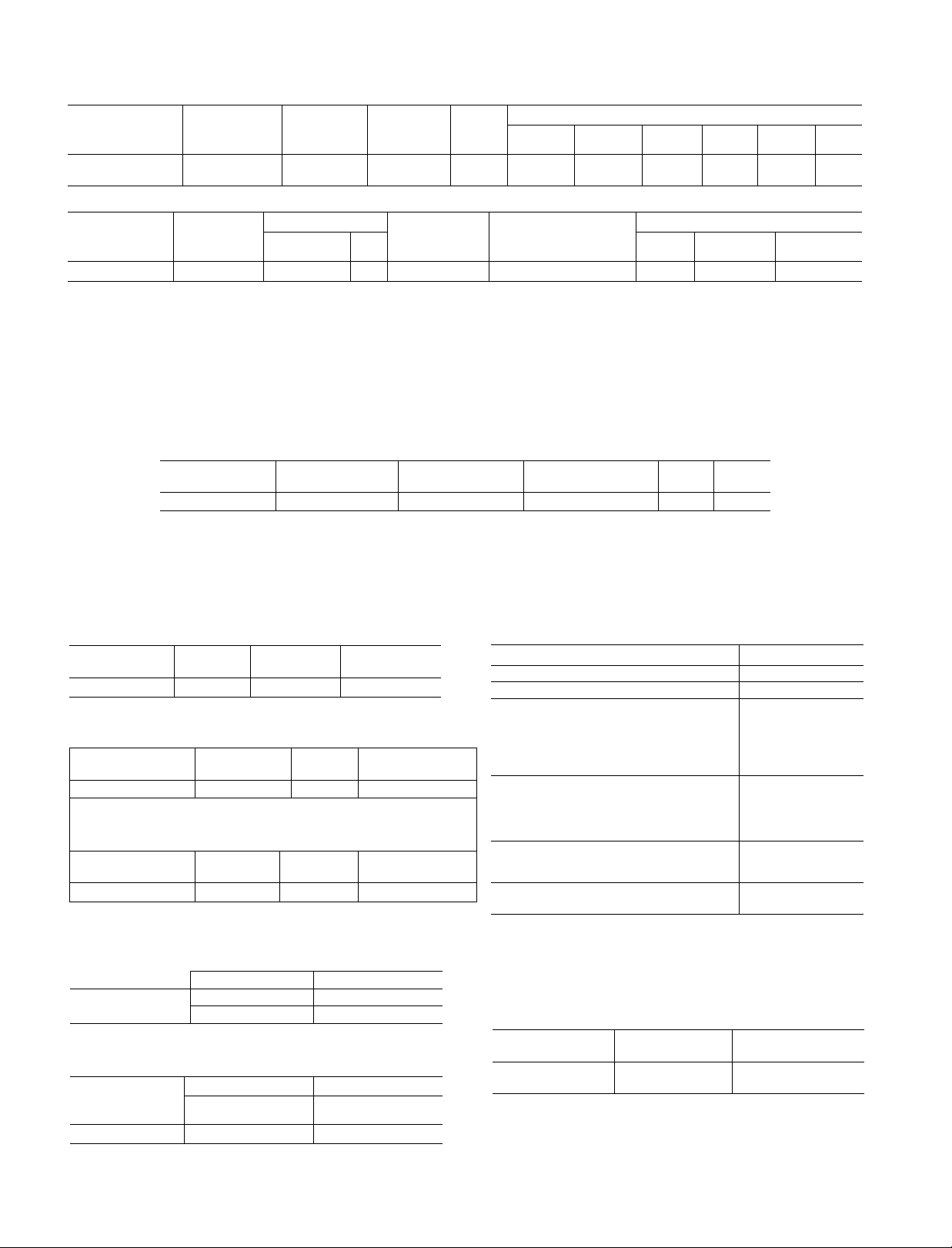
Table 1 — Physical and Electrical Data (Single-Phase, 60 Hz)
SERVICE/
DISCRETE NO
73XCB118301E
SERVICE
DISCRETE NO.
73XCB118301E RC-2
AHAM — Association of Home Appliance Manufacturers
ANSI — American National Standards Institute
DOE — Department of Energy
EER — Energy Efficiency Ratio
FLA — Full Load Amps
PF — Power Factor
CASING
(See Table 5)
305
CAPACITOR
(See Table 4)
LEGEND
KEY NUMBER
(See Table 1)
D-5
LEGEND
FLA — Full Load Amps
LRA — Locked Rotor Amps
COOLING
CAPACITY
(Btuh)‘
18,000/
17,000
FAN MOTOR
Carrier
Part Number
25901051
REPLACEMENT
PART NUMBER
P033-1822
FLA
1 24
R-22
CHG
(OZ. ± 05)
37 0
COMPRESSOR
(See Table 2)
WET
BULB
At F
135
D-5 Z-1
230/208
COMPRESSOR-START
THERMISTOR
At — Entering wet-bulb temperature minus leaving wet-buib temper
*Based on AHAM Standard RAC-1 and ANSI Z234 1
Table 2 — Compressor
OIL RECHARGE
(OZ)
80
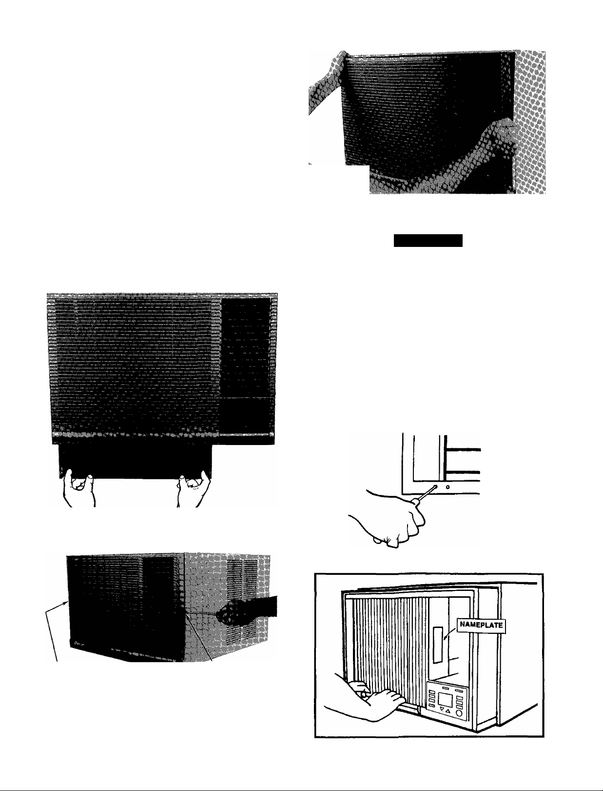
NAMEPLATE
FLA
128
EER
(DOE)PF(%)
96 99
Number
of Tubes
3
Volts
(See Table 3)
ature based on 67 F room wet-bulb temperature and 95 F drybulb outside-air temperature If conditions vary, wet-bulb At will
vary
(Slngle-Ph, 60 Hz)
Voltage
Range
253-187
VOLTS
230/208
Amps
8 3/8 8
CAPILLARY (See Tables 6 and 7)
Data
CD-3
LRA
44 0
Watts
1870/
1840
Insertion
CI-1
Table 3 -- Compressor-Start Thermistor
KEY NUMBER CARRIER
(See Table 1)
Z-1 42320001
NUMBER
VENDOR
NUMBER
CM305C20C
Table 4 — Capacitor
KEY NUMBER
(See Table 1)
RC-2
CARRIER
NUMBER
05706030
MFD
30/5
Table 5 - Casing Dimensions (in.)
KEY NUMBER
(See Table 1)
305 163/4
HEIGHT
WIDTH
253/16
Table 6 — Capillary Data
KEY NUMBER
(See Table 1)
CD-3
Length (± 002)
1 Tube — 47 0 1 Tube - 054
2 Tubes — 29 3
DIMENSIONS (in}
Table 7 — Capillary Insertion
KEY NUMBER
(See Table 1)
CM
DEPTH (In.)
Condenser Coil
Connection Tube
1 1
RESISTANCE
(Ohms)
25
VOLTS
370
DEPTH
233/4
ID(± 002)
2 Tubes — 054
DEPTH (in )
Evaporator Coil
Connection Tube
Table 8 — Receptacle, Fuse Type, Wire Size
UNIT NAMEPLATE VOLTAGE
MAXIMUM NAMEPLATE AMPS
OUTLET RATED VOLTS/AMPS
RECEPTACLE CONFIGURATION
MFR PART NO
Hubbell
P &S
GE
Arrow-Hart
TIME-DELAY FUSE OR CIRCUIT
»
BREAKER SIZE (AMPS)
FUSE TYPE
RECOMMENDED AWG
WIRE SIZE*
LEGEND
AWG — American Wire Gage
‘Based on copper wire at 60 C temperature rating
Table 9 - Electronic Control
ITEM
COOLING-ONLY
CONTROL
CARRIER PART INDOOR
NO THERMISTOR
CEPL130015-01
230/208
12
250/15
5661
5661
GE4069-1
5661
15
Cartridge
14
912-710011-P2216
□El
Page 3
Compressor Replacement
A CAUTION
Stand clear of compressor terminals when working on
compressors With system under pressure, terminals may
blow causing personal injury
Observe the same safety procedures for rotary compres
sors as for reciprocating compressors
When changing compressors
1 Follow all safety codes Reminder use protective
goggles, work gloves, and water-soaked quenching
cloth
2 Shut off all electrical power to unit by removing power
cord from outlet, then disconnect all wiring from the
compressor
3 Apply field-supplied tap-a-lines to the true (closest to
compressor) suction and discharge connections of the
compressor
4 Recover the refrigerant charge from the unit After re
covering, cut the discharge and suction line process tubes
below Sie tube crimps If you choose a good tubing
location for cutting the refrigerant lines initially, the
location is easily accessible when making the final joints
You can braze the oil piping stub into the new compiessor fittings more easily before the compiessor is
put back into the unit
A CAUTION
Oil vapor in piping stubs can ignite from torch flame
and cause serious injury Exeicise extreme care when
brazing, and keep brazing cloth and fire extin
guisher handy for emergency use
PREVENTIVE MAINTENANCE
General
CLEANING — Clean cooling coil and condenser coil Hold
flashlight behind coil to see if all spaces are clear Use a
hooked wire to remove dirt Dust accumulation obstructs or
reduces airflow and results in loss of capacity Coils may
be vacuumed when dry Outdoors, unit can be brushed with
a stiff brush and fins blown out with compiessed aii
Thoioughly clean basepan, motois, fan wheels, other com
ponents, and all drain passages Vacuum insulation Clean
all inside painted surfaces with mild detergent to remove
grease
Clean cabinet and grille Mild detergents reduce electro
static charges on plastic sections of the grille and are good
cleaners Do not use carbon tetrachloride, solvents, or waxes
containing solvents to clean plastic sections
PAINTING — Paint any parts that show evidence of rust
with a good rust-resistant paint
WIRING — Check all wiring for deterioration and all elec
trical contacts for tightness and lack of corrosion
MOUNTING — Make sure unit is secure in window, and
level from left to right and from front to rear according to
installation instructions provided
Check fans to ensure they are correctly positioned, cen
tered in orifice, and tight on shaft
LEAKS — Check any connections that show evidence of
oil oi leaks When unit is propeily installed, centered, and
leveled (see Owners’ Guide), check gaskets and wing pan
els for possible ail leakage
CONTROLS — Check unit to ensure all contiols are func
tioning correctly and unit operation is normal
Vibrations can cause unwanted noise Check to be sure
no piping is vibrating against any side of unit
Connect a nitrogen supply to the unit at one of the tap-
a-line connectors (5 psig maximum flow), leaving the
other connector open to the atmosphere Braze angle
valves with stubs to each process tube
Remove compressor from unit Refer to Compressor
Removal, page 11
Remove tap-a-lines from suction and discharge lines
Carefully braze the holes closed from where the tap-alines were removed
Clean system add or replace liquid line filter drier
For proper cleaning and flushing, use the Carriei
Totalclaim® recovery system or a comparable refriger
ant recycling system
Install new compressor and braze into place with fieldsupplied copper slip couplings
Connect wiring replace wire terminals if necessary
10
Proceed with evacuation and charging Pinch off lines
U
where angle valves were added Cut off angle valves
above pinch-off, and braze tubes
12
Start up unit
System Cleaning/Flushing — For proper cleaning
and flushing, use the Carrier Totalclaim recovery system,
or a comparable refrigerant recycling system
DISASSEMBLY INFORMATION
A WARNING
Before working on any air conditioner, be sure to first
disconnect all electric power to unit to avoid the pos
sibility of electrical shock and personal injury
The Electronic Control Room Air Conditioner is cooling
only and has casing key no 305
All units have a slide-out chassis Units can be serviced
without removing casing
Page 4
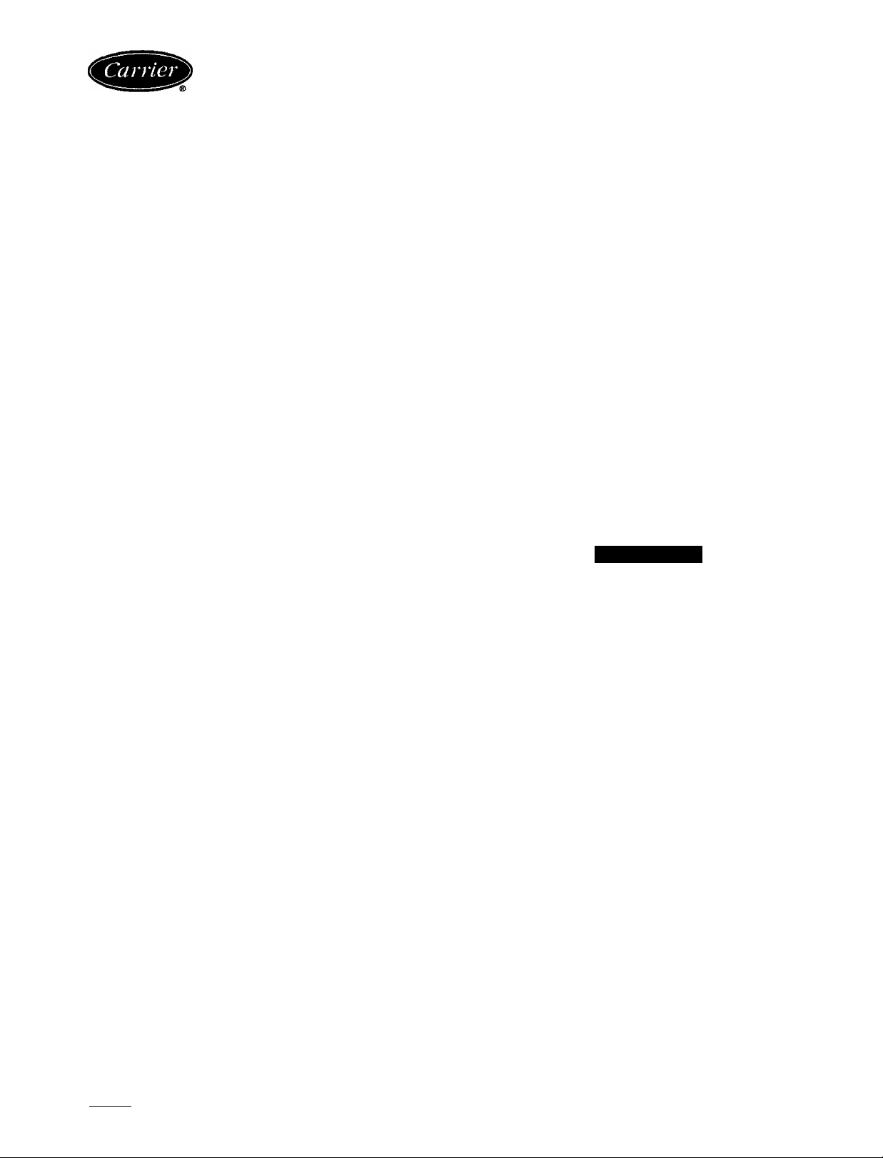
Filter Removal
1 Place index fingers inside the openings on either side of
the filter frame See Fig 1
2 Apply pressure inward toward the center, while pulling
filter down and out
3 Vacuum filter, or wash in lukewarm water Shake off
excess water and dry thoroughly
4 Replace filter by sliding filter upward behind front grille
until filter snaps in place
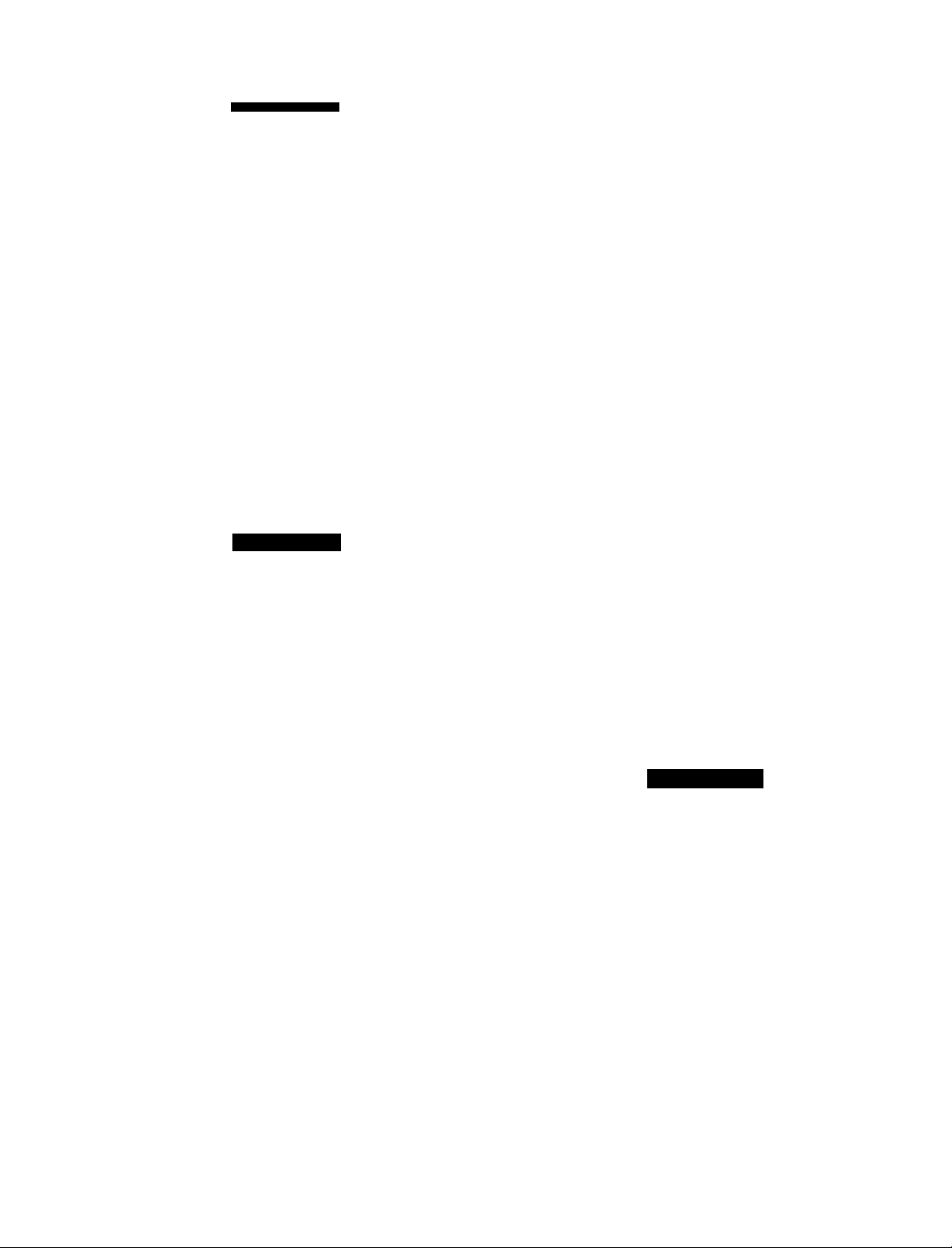
Front Grille Removal
1 Remove 2 screws located on either side of front grille
See Fig 2
NOTE Facing the front of unit, grille screw on the right-
hand side serves as a unit security screw
2 Pull grille out and upward, removing it from chassis
See Fig 3
3 To replace grille, place grille top on unit top edge and
firmly press grille back into position
4 Replace screws
■■
Fig. 3 — Removing Front Grille
Chassis Removal
A CAUTIOH
Coil fins are sharp Use care when removing chassis
from casing to avoid personal injury Do not use plas
tic parts for lifting or pulling, they are not structural
members of the chassis Lift using basepan only Chas
sis is heavy Obtain assistance for lifting
Chassis can be serviced without removing unit casing from
window or wall location
1 Remove front grille See Front Grille Removal instruc
tions, this page
2 If unit has not been installed, remove shipping screw
See Fig 4
3 Slide chassis out from casing See Fig 5
4 Reverse above procedure to reinstall chassis in casing
Be sure to replace and tighten left-hand screw and right-
hand security sciew on the front grille
Fig. 1 — Removing Filter
SCREW (HIDDEN) SCREW (SECURITY)
Fig. 2 — Removing 2 Screws from Front Grille
Fig. 4 - Removing Shipping Screw
Fig. 5 - Sliding Chassis Out from Casing
Page 5

Control Box Removal
1 Remove front grille See Front Grille Removal,
page 4
A CAUTION
Use care when sliding chassis out of casing so that chas
sis does not fall Personal injury and/or damage to the
unit and surroundings can result
NOTE Sliding chassis partly out of casing ensures that the
wiring does not become pinched when the control box is
replaced
2 Slide chassis out of casing far enough to access capac
itor located on back side of partition See Fig 6
3 Remove water seal material from wire raceway See
Fig 6
4 Remove thermistor wire retainer from evaporator coil
See Fig 7
5 Remove screw on lower left front of escutcheon plate
See Fig 8
6 Using a thin screwdriver, lift tab on left side of
escutcheon plate (Fig 9) and swing plate open See
Fig 10
7 Remove screw located in bottom center of control box
See Fig 10
8 Slide out control box, taking care to lift slightly so that
relay board stand-offs clear the basepan See Fig 11
and 12
9 Disconnect fan and compressor leads
When disassembling wiring, use numbered stickers to
identify wire lerds and terminals This aids in quick,
accurate reassembly
10 Reverse above procedure for reassembly
EVAPORATOR THERMISTOR WIRE
COIL RETAINER
Fig. 7 - Removing Thermistor Wire Retainer
PARTITION
SLOTS
'CHASSIS WATER SEAL CAPACITOR
" MATERIAL STRAP SCREW
Fig. 6 — Accessing Capacitor and
Water Seal Material
Fig. 8 - Removing Screw on Escutcheon Plate
CASING
CAPACITOR
Fig. 9 - Lifting Tab on Left Side of Escutcheon Plate
Page 6

Fig. 10 — Escutcheon Piste Open
Electronic Control Board Removal
1 Remove chassis from casing See Chassis Removal in
structions, page 4
2 Remove control box See Control Box Removal instruc
tions, page 5
3 Cut wire tie holding the service cord See Fig 11
4 Gently lift tabs holding LCD (liquid crystal display) board
to rear side of escutcheon plate and lemove board See
Fig 13
5 Release pressure on relay board stand-offs (Fig 12) at
control box, lemove relay board Save stand-offs for
reassembly
6 Disconnect air sweep motor wire leads See Fig 14
A CAUTION
When replacing electronic control board, be sure the
flying wire is attached to the 220 V voltage connection
or electronic control board will be damaged See
Fig 15
7 Attach the flying wire to the 220-V voltage connection
It is important to connect flying wire correctly or elec
tronic control board will be damaged See Fig 15
8 Reverse above procedure for reassembly
LIQUID CRYSTAL
DISPLAY (LCD)
AIR SWEEP
MOTOR CAMWIRE TIE
Fig. 11 — Control Box Removed from Unit
Fig. 12 — Relay Board Stand-Offs
Fig. 13 - Liquid Crystal Display (LCD) Board
AIR SWEEP
MOTOR
AIR SWEEP MOTOR
WIRE LEADS
n 1 i ^
SERVICE CORD
Fig. 14 — Electronic Control Board
Removed from Control Box
Page 7

, ,,— lcd
/y. ■ S“™
f
-------
FLYING
WIRE
(SHOWN
CONNECTED
TO 220 V )
A CAUTION
When replacing electronic control board, be sure
flying wire is attached to the 220-V connection or
electronic control board will be damaged
Fig. 15 — Electronic Control Board
RELAY
BOARD
Remove 2 screws securing partition to basepan as shown
in Fig 16, and 2 screws on left side (Fig 17), and one
screw on rear side of partition (Fig 18), in area of
motor
Remove 2 screws securing evaporator scroll to evapo
rator tube sheet See Fig 17
Remove 4 screws (2 on right side and 2 on left side)
securing condenser orifice to condenser coil tube sheet
See Fig 16 for location of right-side screws, left-side
(2) screws are in similar location on left side
Remove compiessor terminal cover Disconnect wires
from compressor and external oveiload protector ter
minals Label wires to aid in reassembly See Fig 16
1
Remove fan motor clip See Fig 18
8
Carefully disengage one of the vertical air deflectors,
allowing access to assist in removing air handling sys
tem assembly See Fig 19
9
Carefully lift assembly from chassis See Fig 20
10
Reverse above procedure for reassembly, ensuring air
handling system is positioned correctly Tighten all screws
EVAPORATOR
COIL
EVAPORATOR
SCREW
(1 OF 2}
BASEPAN
CONDENSER
ORIFICE
COMPRESSOR
TERMINAL
/COVER
CONDENSER
ORIFICE
SCREW (1 OF 4)
■COMPRESSOR
—CONDENSER
CONDENSER
COIL
COIL SCREW
{1 OF 2)
[SEE NOTE 1)
Capacitor Removal
Slide chassis out of casing far enough to access capac
itor located on back side of partition
Pull back rubber boot
Before disconnecting, discharge capacitor by shorting ca
pacitor across terminals
Remove screw fastening capacitor strap to partition and
remove strap (See Fig 6 )
Carefully disconnect wires from capacitor terminals
Reverse above procedure for reassembly
Air Sweep Motor Removal
1 Remove control box and electronic control board See
Control Box Removal instructions, page 5, and Elec
tronic Control Board Removal instructions, page 6
2 Carefully disconnect air sweep motor (Fig 14) wire ter
minations from electronic control board
3 Carefully pull plastic air sweep motor cam from shaft
See Fig 11
4 Remove 2 screws securing air sweep motor to control
box and remove motor
5 Reverse above procedure for reassembly
Air-Handling System Removal
1 Remove chassis from casing See Chassis Removal in
structions, page 4
2 Remove control box See Control Box Removal in
structions, page 5
PARTITION ORIFICE SCREW
SCREWS (2) (10F4)
NOTES
1 Second condenser coil screw is located on the back of unit
2 Third and fourth condenser orifice screws are located in same
area on opposite end of condenser orifice
CONDENSER
Fig. 16 — Unit Chassis
TOP GUSSET
LEFT SIDE
PARTITION SCREW
SCREW SECURING
EVAP SCROLL TO
EVAP TUBE SHEET
SCREW SECURING
EVAPSCROLL TO
EVAP TUBE SHEET
Fig. 17 — Preparing to Lift Air-Handling System
Page 8

FAN MOTOR
CLIP (SPRING)
AIR HANDLING SYSTEM
REMOVAL SCREW
LEFT SIDE SCREW TOP
Fig. 18 — Removing Fan Motor Ciip
PARTITION
REAR SIDE
PARTITION SCREW
Evaporator and Condenser Coils Removal (See Fig. 16)
1 Recover all refrigerant from system using a Carriei
Totalclaim® or Carrier Totalsave® recovery system,
or a comparable refrigerant recovery system Refer to
Service section, page 1
2 Remove chassis from casing See Chassis Removal in
structions, page 4
3 Remove air-handling system See Air-Handling System
Removal instructions, page 7
4 Cut interconnecting tubing and remove evaporator coil
from basepan by removing 2 evaporator screws See
Fig 16
5 Cut interconnecting tubing and remove condenser coil
from basepan by removing 2 condenser coil screws See
Fig 16
6 Reverse above procedure for reassembly Reconnect tub
ing using field-supplied slip coupling Recharge system
Exhaust Door Removal (See Fig. 21)
1 Remove chassis from casing See Chassis Removal in
structions on page 4
2 Remove control box from chassis See Control Box
Removal instructions, page 5
3 Remove air-handling system See Ait-Handling System
Removal instructions, page 7
4 Remove 3 screws securing partition to indoor plastic scroll
(See Fig 22 and 24 )
5 Carefully separate sheet metal partition slots from scroll
tabs on both sides by spreading sheet metal sides apart
Remove scroll from sheet metal partition (See Fig 6 )
Exhaust door and cable assembly from door to rotary
lever (Fig 21) are now exposed for required repairs or
adjustments
6 Reverse above procedure for reassembly
Fig. 19 — Disengaging Vertical Air Deflector
-.'.if
Fig. 20 — Removing Air-Handling System
ROTARY LEVER
CABLE
EXHAUST DOOR
SPRING CUP
Fig. 21 — indoor Plastic Scroll Assembly
Page 9

INDOOR PLASTIC
SCROLL (HIDDEN)
SCREWS
{2 OUT OF 3)
NOTE: Third screw is located on ieft side of partition as viewed from
front of unit
SHEET METAL
PARTITION
TYPICAL STRAINER
LOCATION
CONDENSER
ORIFICE
CONDENSER
COIL
Fig. 22 — Screws Securing Partition to Indoor
Plastic Scroll Assembly
BLOWER WHEEL
Indoor Blower Wheel Adjustment or Removal
1 Remove ah-handling system See Air-Handling System
Removal instructions, page 7
2 Mark shaft at a point where wheel hub and motor shaft
meet to aid in reassembly
3 Remove 3 screws securing partition to evaporator (in
door) scroll See Fig 22 and 24
4 Separate chassis from partition by disengaging at parti
tion slots See Fig 6
5 Remove spring metal clip from blower wheel hub See
Fig 23
6 Slide off blower wheel from motor shaft
7 Reverse above procedure for reassembly
NOTE Scroll enclosure is insulated with expanded poly
styrene The distance between indoor blower wheel and scroll
enclosure is %4 inch See Fig 25
PARTiTiON
SLOTS
'•■T' s
Fig. 23 — Removing Indoor Blower Wheel
Fig. 24 — Screws Securing Partition to
Evaporator Scroll
Page 10

DETAILA-A
7/64 IN
(3 mm)
t '
------------------------------
VI
Ì
10
Fig. 25 — Distance Between Indoor Blower Wheel and Partition for Cooling-Oniy Units
1 1
Propeller Fan Adjustment or Removal (See
Fig. 26)
1 Remove air-handling system See Air-Handling System
Removal instructions, page 7
2 Mark shaft at a point where fan hub and motor shaft
meet to aid in reassembly
3 Remove spring metal clip from fan hub See Fig 26
4 Remove fan from motor shaft
5 Reverse above procedure for reassembly
IMPORTANT When replacing fan hub, be sure to
place fan hub at the end of the motor shaft
Fan Motor Removal (See Fig. 27)
1 Remove air-handling system See Air-Handling System
Removal instructions, page 7
2 Remove indoor blower wheel and propeller fan See
Indoor Blower Wheel Adjustment or Removal and
Propeller Fan Adjustment or Removal instructions, page 9
and this page
3 Carefully disconnect fan motor wiring from plug
4 Remove 3 screws securing motor to partition See
Fig 27
5 Reverse above procedure for reassembly
SCREW
SCREW
PARTITION
SCREW
SPRING METAL CUP
Fig 26 -- Removing Propelier Fan
Fig. 27 - Removing Fan Motor
10
Page 11

Compressor Removal (See Fig. 16)
NOTE Befoie removing compiessor, refer to Service sec
tion, page 1, and Carrier Standard Service Techniques
Manual, Chapters 1 and 2
1 Recover all refrigerant from system using a Carrier
Totalclaim® or Carrier Totalsave® recoveiy system, or a
comparable refrigerant recovery system
2 Remove chassis from casing See Chassis Removal in
structions, page 4
3 Remove compressor terminal cover (See Fig 16 )
4 Disconnect wires from compressor and external
overload protector terminals Label wiies to aid in
reassembly
NOTE Some models may have compressors with inter
nal overload protectors
5 Replace external overload piotectors, if needed
6 Disconnect piping Refer to Compressor Replacement
section, page 3, being careful to observe all CAUTIONS
Remove compressor mounting hex nuts
Strainer Removal and Replacement
NOTE One strainer is installed in the interconnecting tub
ing between the condenser and capillary tube (For typical
location, see Fig 22 )
1 Remove chassis from casing See Chassis Removal in
structions, page 4
2 Recover all refrigerant from system using a Carrier
Totalclaim® oi Carrier Totalsave® recovery system, or a
comparable system Refer to Service section, page 1
3 Cut tubing 1 in from capillary tube insertion point
4 Use a thin piece of wiie to lemove strainer from tubing
5 Insert new strainei into tubing Reassemble tubing with
field-supplied copper coupling and recharge system
SERVICE POINTS
(Check Annually)
1 Clean evaporator and condenser coils Use a hooked
wire, bristle brush, compressed air, or a vacuum cleaner
to remove dirt from fins
2 Clean basepan and other painted surfaces
3 Clean all drain passages
4 Clean motor and fans
5 Vacuum clean the insulation
6 Paint parts that show evidence of rust with a good rust-
resistant paint
7 Check refrigerant connections for evidence of leakage
Repair if necessary
8 Check wires for deterioration
9 Check damper controls
10 Fans should be tight on motor shaft
11 Run the unit and eliminate any piping vibration
12 Check to be sure protective sleeve is in place around
thermistor
11
Page 12

TROUBLESHOOTING
SYMPTOM AND
PROBABLE CAUSE
COMPRESSOR DOES NOT RUN
Opening in Power Circuit
1 Control off
2. Blown fuse
3 Defective wiring
4 Defective service cord
5 Loose electrical connections
6 Faulty switches, thermostat, or fan
Compressor Power Supply Open
1 Loose leads at compressor terminals
2 Defective motor overload switch
3 Defective capacitor
4. Open compressor windings
5. Seized compressor
COMPRESSOR RUNS BUT CYCLES
Fan Operating Erratically
1 Loose lead at fan motor
2. Defective or burned out motor
3 Outdoor air restricted or recirculating
4 Overcharge or noncondensables in system
5 Restricted discharge line
6 Defective motor overload switch
Cycles on Compressor Overload
1 Defective run capacitor
2 Defective compressor bearings or valves
3 Greatly restricted indoor air (Iced evaporator coil)
4 Low refrigerant charge
5 Evaporator capillary restricted
6 Liquid line restricted
7. Compressor hot
8 Weak or inconsistent iine power
INSUFFICIENT COOLING
Cooling Air Not Adequate
1 Dirty filter or coil
2. Iced evaporator coil (slightly low refrigerant charge)
3 Defective fan motor
Condenser Air Not Adequate
1 Condenser air restricted
2 Dirty coil
3 Defective fan motor
Unit Undersized
Air Leakage
Capillary Restricted
Compressor Flooding
1 Unit overcharged
2 Low evaporator airflow
AIR SWEEP NOT WORKING
1 Cam disengaged from lever
2 Air sweep motor failure
MESSAGE DISPLAY CODES
d
CP
PF
01
PROBABLE REMEDY
1 Reset control button
2 Replace fuse
3 Replace wiring
4 Replace service cord
5 Tighten connections
6 Replace defective component
1 Tighten leads
2 Replace switch
3 Replace capacitor
4 Replace compressor
5 Replace compressor
1 Tighten lead
2 Repair or replace motor
3 Check for dirty filter, proper clearances around unit —
remove any obstructions
4 Recover refrigerant, evacuate and recharge system according to
nameplate specifications
5. Check for obstruction in line, replace tubing if required
6 Replace switch
1 Replace capacitor
2 Replace compressor
3 Defrost evaporator coil
4 Add charge according to approved method
5 Replace capillary
6 Replace strainer
7 Verify refrigerant charge
8 Check line voltage at time of compressor start-up
1 Clean as required
2 Recharge
3 Replace fan motor
1 Check for obstructions and dirty filter Remedy as required
2 Clean coil
3 Replace fan motor
Re-evaluate unit for proper capacity
Check caulking around sleeve Repair if necessary
Replace capillary
1 Recover refrigerant, evacuate and recharge system according to
nameplate specifications
2 Clean filter and/or evaporator coil
1 Activate motor and allow cam to re-engage
2 Replace motor
■
Unit in Dehumidification mode
Unit in Compressor Protection mode Allow 2 minutes for restart
Power failure
Room air thermistor failure
Copyright 1995 Carrier Corporation
Book 11 }4 PC 131 Catalog No 537-323 Printed in USA Form73XC-1SS Pg 12 1-95 Replaces: New
Manufacturer reserves the right to discontinue, or change at any time, specifications or designs without notice and without Incurring obligations
 Loading...