

Page 1
Carrier
A Packaged Hermetic
Centrifugal
Liquid Chillers
19
Series
100-2000 tons
(352-7034 kW)
■ ■ I
On stream, on budget with energy-saving
solutions to comfort air conditioning
and process cooling challenges!
© Carrier Corporation 1979
Form 1 9-2P
Page 2

The 19 Series: Built to save energy, save you money and get the job done right
Dr. Willis Carrier invented centrifugal refrigeration in 1922
and today, more than half a century and 25,000 machines
later. Carrier hermetic centrifugal liquid chillers still lead
the way in comfort air conditioning and process cooling.
What’s more, the modern day 19 Series centrifugals are
specifically designed to afford significant dollar savings on
utility bills, in every way possible.
The Carrier 19 Series centrifugal design philosophy has
always been to offer a variable line which meets each unique
specification while at the same time maintaining low first
costs and low operating costs. Incorporated in this
philosophy are such features as the 19 Series inline
impeller design, hermetically sealed compressor-motors,
gear drives and refrigerant options. The success of this
concept can be seen in the 25,000 plus machines which
have been applied to date.
Carrier’s hermetic centrifugals have always used various
refrigerants at different tonnage ranges in order to keep
the heat exchanger size and cost down. Now, over and
above the low first cost concept, Carrier offers refrigerant
options to meet your specific job requirements in the most
efficient way possible.
Tbe full hermetic line consists of four models, each with
a cycle, refrigerant and tonnage range specifically matched
to your application demands. From 100 tons (352 kW) to
2,000 tons (7034 kW), the Carrier hermetic centrifugals are
capable of performance at levels of .85 KW/Ton (3.0 KW/
kW) to .65 KW/Ton (2.3 KW/kW) and lower, depending on
design conditions. With features such as mix-match capa
bility, high performance heat exchangers, refrigerant
options, multi-pass water boxes as well as tbe 19 Series her
metic compressor designs, a Carrier centrifugal can be opti
mized to meet any job requirement. The “Low Energy Con
sumption Curve” illustrates performance levels possible
within the tonnage capabilities of the 19 Series hermetic line.
You get the most efficient, most reliable, energy-conscious
and completely packaged machine for your particular appli
cation. The hi-lift capabilities (up to 100 F) make the 19
line ideally suited for brine chilling, ice rink applications
and process cooling. In areas with cooling tower restric
tions, you can even specify a hi-lift Carrier centrifugal for
use with closed circuit water condensing systems. The
versatile Carrier centrifugals are also designed for low-lift
requirements of today’s energy-conscious market.
Not only can Carrier Sales Engineers optimize your
refrigeration requirements but they can optimize your total
system as well. Thru various specialized computer pro
grams, for example, a Carrier Sales Engineer can vary your
leaving chilled water temperature a degree or increase your
chilled water temperature differential from 10 to 14 F and
show how the total system is affected with respect to
operating costs. In this complex market of low energy con
sumption as well as low first cost, Carrier can offer you
productive ways to reduce your costs.
Energy-saving, precision
design: extends compressor
motor life, saves on
operating costs, increases
electrical efficiency
• Hermetic design
• Gear-drive compressors
• In-line impeller design
• Refrigerant-cooled motors
• Solid state capacity control
• Thermal purge
• 55 F (13 C) condenser water
• Flash and thermal economizer
• Multi-pass water boxes
• Compressor-motor-heat exchanger mix-match
Engineering excellence
provides lower first costs
and years of trouble-free
service
• Single-unit construction
• Factory-wired oil pump starter
• Permanent shipping bases
• Prepiped motor lubrication package
• Storage tank
• Factory start-up
• Integral chilled water sensor
• Elapsed-time indicator
Carrier’s computer approach to matching the machine
and capacity to a specific application gives you access to
literally thousands of condenser, compressor, cooler,
refrigerant and pass combinations. Initial costs arc lower
because you select only what you need — a smaller
package. Operating costs are reduced because the mix
matching of components allows lower energy consumption
selections. In addition, a Carrier Sales Engineer has the
ability to optimize selections, by varying conditions, thru
the use of the Performance Programs. Should your job
requirements demand performance other than what is
shown in this catalog, contact your Carrier Sales Engineer
(refer to page 50 for the office nearest you). Thru com
puterized selection he will be able to design your “custom
built” hermetic centrifugal.
D
Computer selection saves
time, cuts costs
Full line centrifugal service
centers assure optimal care
of your unit
Convenience options offered
for added energy efficiency,
‘tailor-made’ systems
Page 3
s
g
U.
(T
UI
a
KWAW KW/TON
f 2SÎ U
( 36;
■: 24;
22;
20) '
s 18'
( 16) [—
"Carrier Offers Low Energy-Consumptiors Selections"
Î^OCO) )20C0)
riOOO) (400C)
CAPACITY
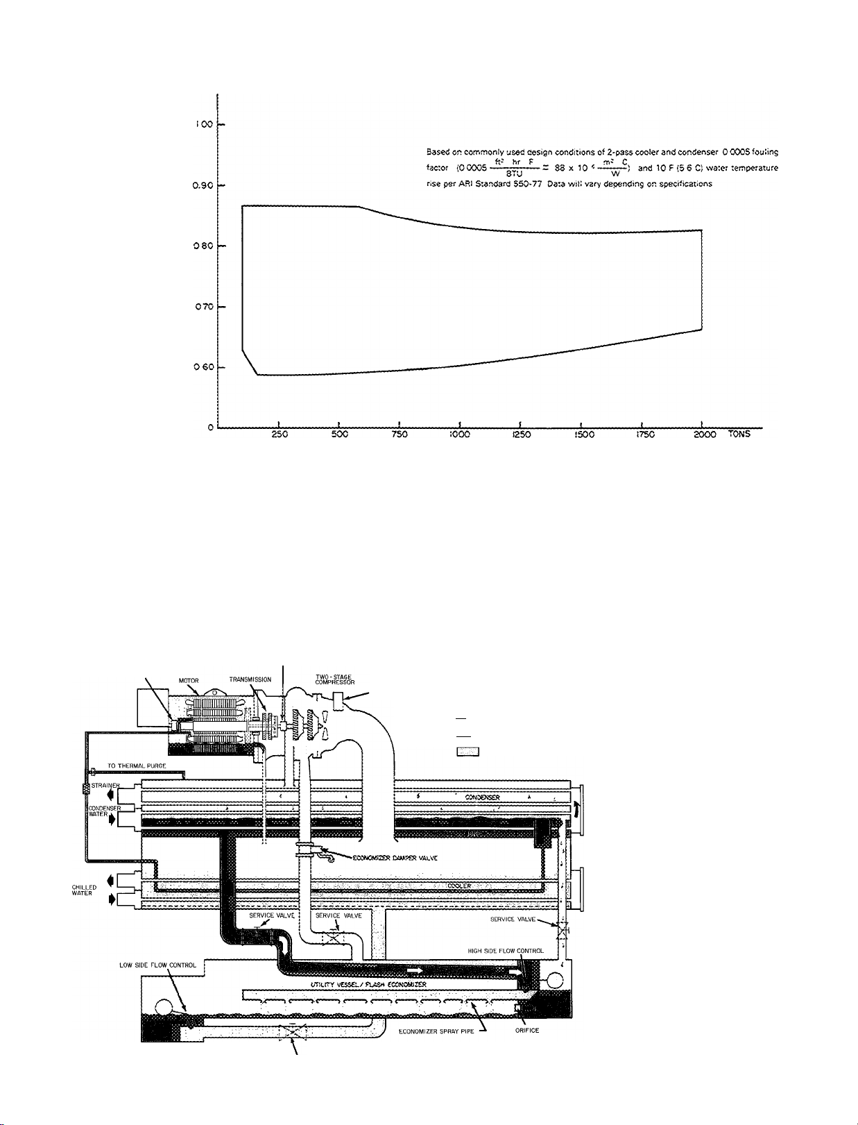
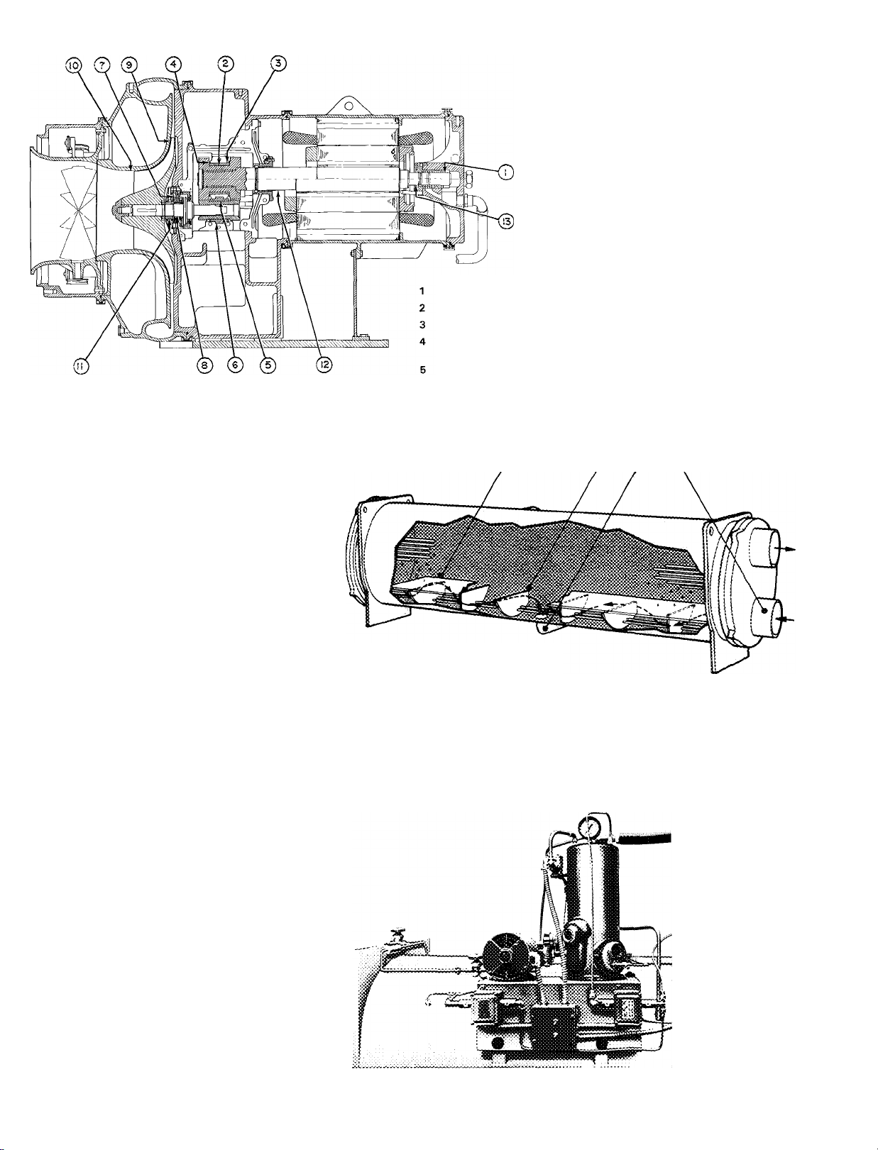
19 Series Centrifugals —
The ideal refrigeration cycle
BEARING AND SEAL
BEARING AND SEAL
VANE MOTOR
i I REFRIGERANT VAPOR
tliiSfel REFRIGERANT LIQUID
SERVICE VALVE
{5COC)
REFRIGERANT LIQUID/VAPOR
•SOCO)
^7000) kW
Carrier centrifugals use refrigerant
(R-11, 114, 12 or 500) in a standard
compression, single- or two-stage
refrigeration cycle. System water in
the cooler is chilled as its heat is
transferred to refrigerant at low tem
perature and pressure. As heat is re
moved from the water, the refrig
erant vaporizes and is drawn into the
compressor at a rate controlled by
the degree of the guide vane opening.
As the compressor raises the vapor
pressure, the saturation temperature
of the refrigerant rises above that of
the condenser water. Refrigerant
vapor is discharged directly into the
condenser, where relatively cool
condenser water removes heat from
the vapor, causing it to condense
again to liquid. The heated water
leaves the system, returning to a
cooling tower or other heat rejection
device. The liquefied refrigerant then
leaves the condenser, draining into
a chamber where a variable metering
device regulates refrigerant flow and
maintains a liquid seal to prevept
vapor from passing into the cooler.
As the refrigerant liquid goes thru
this metering device, part of it vapor
izes because of reduced pressure,
cooling the remaining liquid to the
temperature at which the cycle
began.
Page 4
Energy-saving, precision design: extends compressor motor life, saves on operating costs, increases electrical efficiency
Hermetic design
Hermetic compressor design keeps
motor free of airborne dirf and mois
ture. It also isolates motor to keep heat
and sound from equipment room.
Eliminates shaft seal with its potential
refrigerant leakage.
■ Gear driven compressors
Gear driven compressors allow more
flexibility in selection than direct drive
because gear ratios can be fitted to
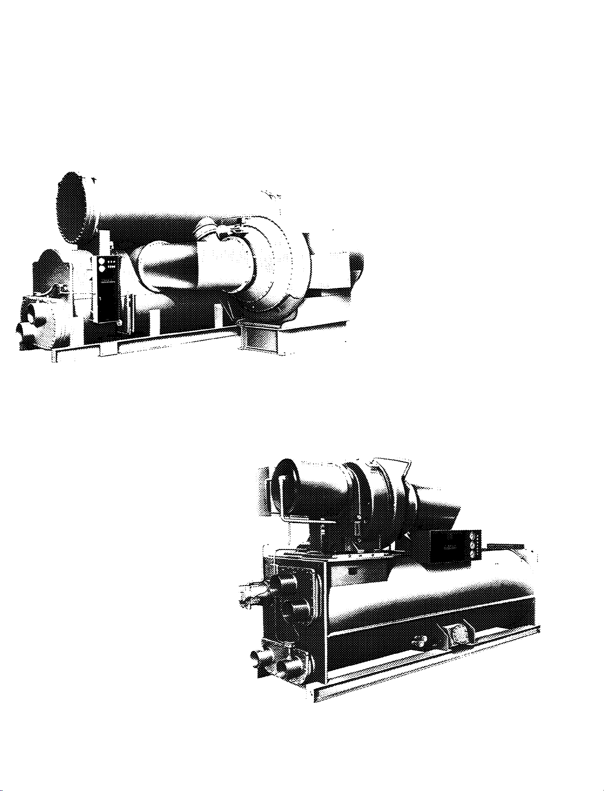
19CB
particular application. Gear driven
compressors also allow optimum im
peller speed, higher head applications
and increased operating efficiency.
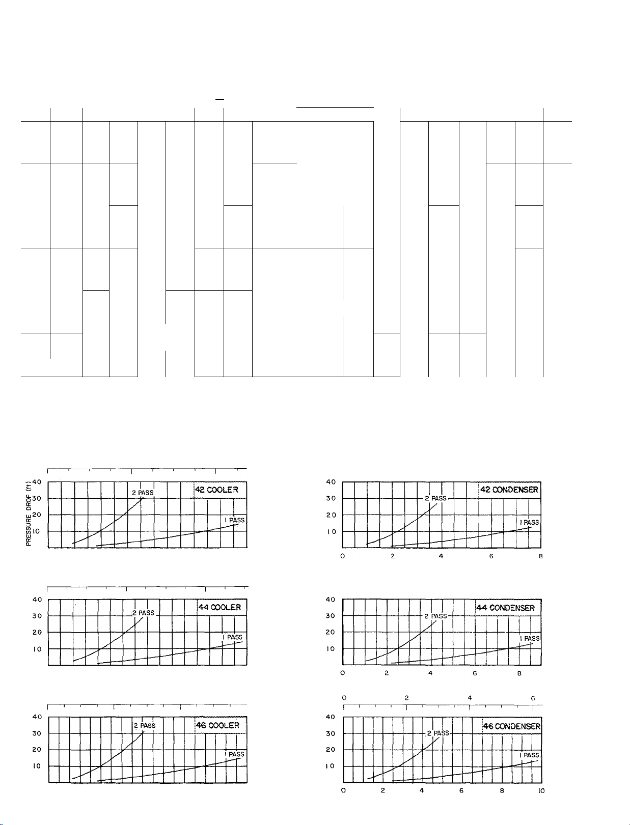
Multi-pass water boxes
The complete 19 Series line offers 1,2,3
and 4 pass water boxes on both the
coolers and condensers. The result is
better heat transfer when needed —
reducing operafing costs. In addition,
all pass arrangements are available at
no extra cost.
Refrigerant-cooled motor
All 19 Series compressors have
refrigerant-cooled motors that operate
at low, even temperatures throughout
the motor windings to insure long motor
life at high electrical efficiency.
19DH
Page 5
Solid state capacity control
The capacity control module offers
solid state compactness and reliability,
with smooth and precise capacity mod
ulation from 100% to 10% of full load,
without hot gas bypass. It is more
efficient in maintaining leaving water
temperatures than any other type of
control. The convenient, centrally
located control center provides fully
automatic machine operation, com
plete with a full complement of safety
interlocks. Check operating status at a
glance, easily monitor all system oper
ating points. The highly sensitive,
factory-installed thermistor probe, solid
state amplifier, and guide vane actuator
are precisely matched and fully re
sponsive to changes in leaving chilled
water temperature. They help to main
tain your selected design temperature
throughout all operating load condi
tions. The result is efficient, trouble-free
operation with longer life expectancy.
All control connections can be made
quickly to a single terminal strip; and
once the solid state control has been
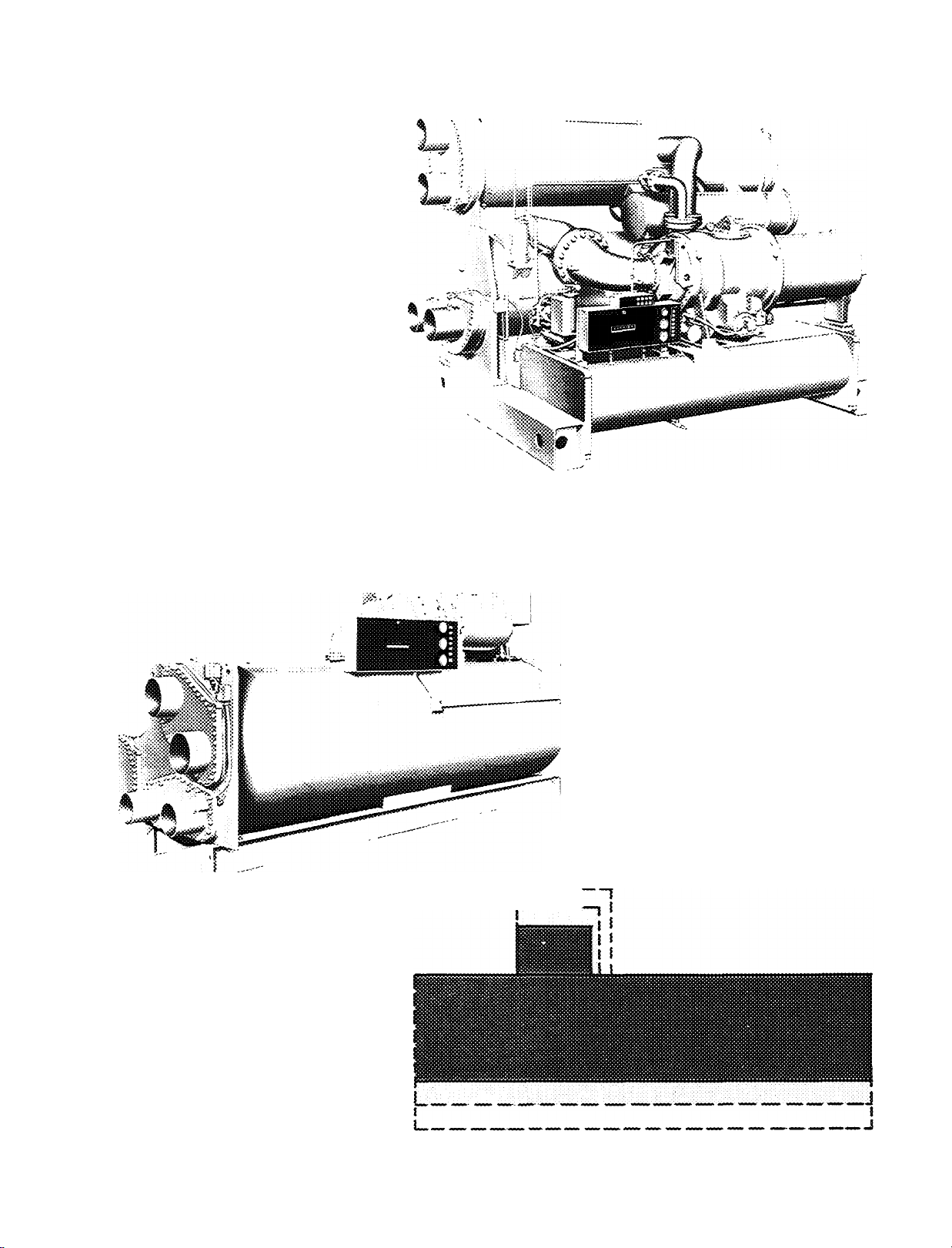
19EB
19FA
calibrated, control settings may be
changed without additional field
calibration.
55 F (13 C) condenser water
The Carrier metered refrigerant design
allows the 19 Series chillers to operate
efficiently with condenser water tem
perature as low as 55 F (13 C) without
condenser water bypass or mixing
tanks. The 55 F (13 C) condenser water
means reduced head pressures which in
turn means lower horsepower require
ments The end result is lower energy
costs and lower annual operating costs.
In addition, the absence of a condenser
water bypass and mixing tanks add up
to lower first costs and lower installation
costs.
m
LZZZ
Compressor-motor-
heat exchanger mix-match
Each model within the 19 Series line
has the capability of mix-matching
various heat exchanger sizes with an
array of compressor-motor combina
tions. As illustrated, mix-matching
allows you to mount a small capacity
compressor on a large heat exchanger.
This design concept optimizes specified
conditions, improving full and part load
performance.
Page 6
19DH
In-line impeller design
In-line impeller design, with diaphragm
between stages, allows for more flexi
bility in compressor component selec
tion, which results in first cost savings
on other machine components. Also
provides higher head capabilities, pre
vents uneven loading and allows for
routine, easy maintenance.
— Motor End Bearing
— Gear Journal Bearing
— Driving Gear Bearing To Housing
— Thrust Clearance on Gear
Bearing (each side)
— Pinion Gear Journal Bearing
— Pinion Gear Bearing To Housing
— Thrust Bearing
LEGEND
8
9
10
11
12
13
— High-Speed Journal Bearing
— Front of Impeller to Volute Wall
— Impeller Eye to ID of Inlet Ring
— Labyrinth Behind Impeller to
Spacer Ring
— Labyrinth Behind Transmission
and Motor Shell
— End-Bell Bearing Labyrinth
Flash and thermal economizer
Two-stage models thru 1,600 ton
(5627 kW) capacity feature a thermal
economizer. The thermal economizer
shown brings warm condensed refriger
ant into contact with the inlet (coldest)
water tubes where water as low as 55 F
(13 C) may be flowing. This low tem
perature water subcools the refrigerant
so when it moves on in the cycle it
has greater cooling potential, thus im
proving cycle efficiency and reducing
power/ton requirements. In addition, all
two-stage models employ a flash econo
mizer, not shown, to further improve
cycle efficiency. The liquefied refrig
erant leaves the condenser thru a
metering device and flows into the flash
economizer where the normal flashing
of part of the refrigerant into vapor is
used to cool the remaining refrigerant.
The flash vapor is diverted directly to
Thermal purge
The thermal purge effectively removes
air, water, and noncondensables from
the refrigerant system, promoting
greater operating efficiency and lower
maintenance costs. It needs no water
connections or air-cooled condenser.
It performs normal system purging
during periods of operation on R-11 and
R-114 machines. In addition, on R-11
machines it doubles as a pump for leak
testing or machine evacuation after
servicing. It also provides recovery of
refrigerant under normal purging
conditions.
19FA THERMAL ECONOMIZER
the compressor’s second stage so that it
does not have to be pumped thru the full
compression cycle. The flash econo
mizer generates savings and signifi
cantly lowers operating costs.
14 *5
14 — Thermal Economizer Partition Plate
15 — Refrigerant Flow Baffle
16 — Refrigerant Liquid Drain Line
17 — Condenser Water Inlet
J6 17
LEGEND
19DH
Page 7

Engineering excellence provides lower first costs and years of trouble-free service
Single unit construction
Carrier centrifugals are the most com
pletely packaged units of their kind.
Chiller is shipped as a single unit com
plete with integral storage tanks where
required. Ready for quick connection
to water and electrical sources at the
job site. (Compressor is field installed
on the 1,600-2,000 ton (5627-7034 kW)
models; the heat exchanger and
economizer are factory assembled.) In
addition. Carrier centrifugals arrive at
the job site with controls mounted and
pre-wired including the chilled water
thermistor. All control connections can
be made to a single terminal strip. Single
unit construction assures minimum in
stallation time, minimum installation
costs.
Factory-wired oil pump starter
Models available for U.L. listing feature
a factory-wired oil pump starter The
starter is factory wired to the machine
with overloads and contactors sized by
Carrier for U.L. compliance. The entire
assembly is factory mounted to save in
stallation time and field labor costs.
Permanent shipping bases
Rigging can be done faster and the need
for costly concrete bases and supports
is eliminated with 19 Series permanent
shipping bases.
Prepiped motor lubrication package
The oil pump, motor, filter, cooler,
pressure controls, and electrical ter
minals are all prepiped and wired to
save on-site labor costs and installation
headaches.
Storage tank
The storage tank is an integral part of
the machine design on all R-12 and
R-500 units. No additional pipings,
fittings or valves are needed. No in
creased floor space is required which
saves you first cost dollars. Servicing or
testing may be easily accomplished
without time-consuming transfer to
separate containers which saves you
service dollars. Models using R-114
offer the storage tank as an option at
minimal cost. They are constructed to
ASME code requirements and include
all necessary connections for refrig
erant transfer system.
Factory start-up
Carrier start-up service for your ma
chine is included in the purchase price.
This assures you of trouble-free, work
ing installation right from the start. It
includes refrigerant transfer, leak test
ing and precision calibrating of the solid
state control settings and safety control
settings.
Integral chilled-water sensor
A chilled-water thermistor probe is fur
nished, installed in the leaving chilled
water nozzle as part of the machine’s
standard control system. A signal from
the sensitive solid-state device to the
central control module automatically
initiates immediate adjustments to com
pressor capacity. This eliminates the
need for accessory pneumatic equip
ment, separate sensing devices, saves
you initial equipment cost, and makes
installation easier, more economical. As
part of the machine’s standard control
system, it does not have to be specified
in another portion of the job, and thus
further reduces first and installation
costs.
Elapsed-time indicator
Every Carrier centrifugal features an
elapsed-time indicator to provide an
immediate and constant record of
machine operating hours. No over- or
underestimating when scheduling
maintenance. Mounted outside of the
control box for easy visibility.
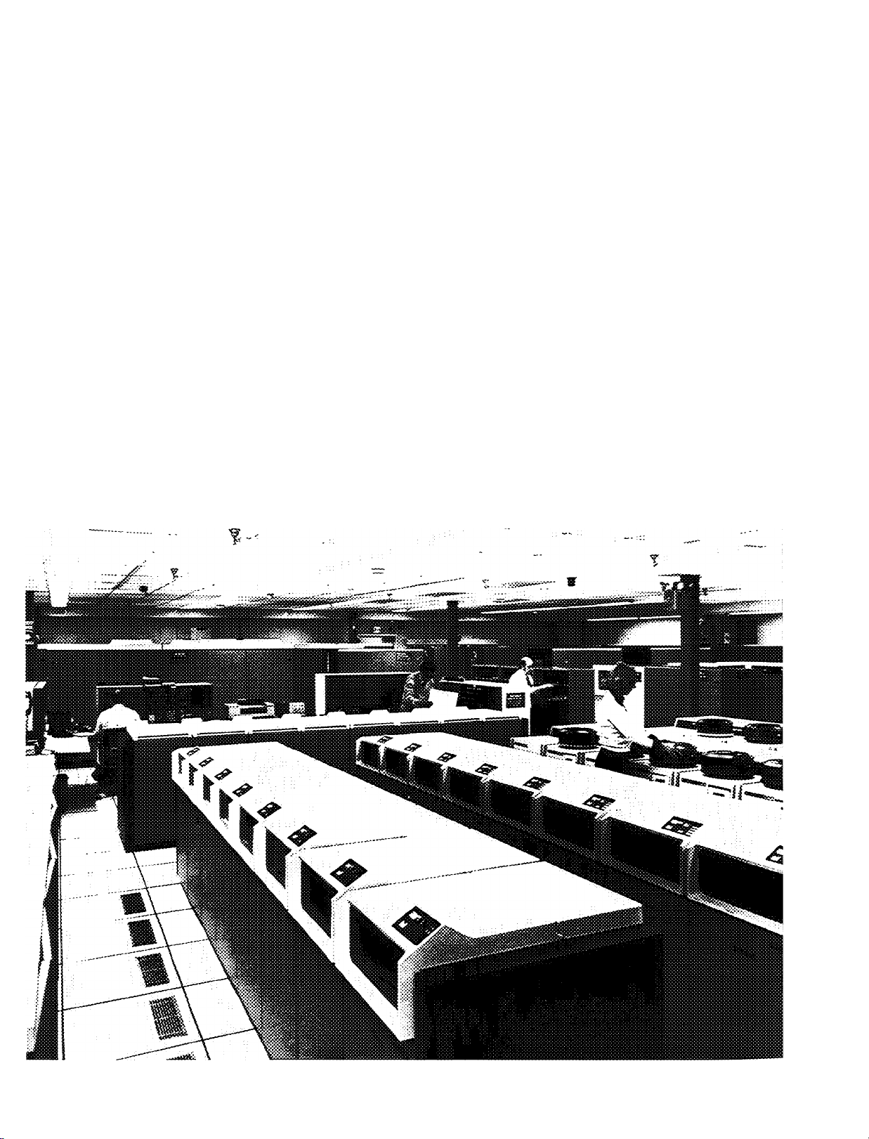
Full line centrifugal service centers assure optimal care of your unit.
When you specify Carrier, you get a complete service
organization unequaled in the industry. Carrier Service
j Operations is a national organization in over 150 key loca
tions throughout the United States and Canada. This is
the one service organization that has grown up with the
air conditioning industry. Today, more and more owners
rely on Carrier Service Operations for an in-depth, practical
approach to energy conservation. This extraordinary full
time commitment to quality maintenance and service
proves Carrier’s interest in continued customer satis
faction. Your centrifugal, in fact your entire HVAC system,
will be in the care of people who are fully versed on the
design, manufacture, installation, start-up and maintenance
of your equipment.
Page 8
Computer selection means “custom built” machinery — saves design time and lowers cost.
Supplementing the selections in this publication, Carrier
has, for your convenience, developed computer selection
and performance programs for 19 Series hermetic units
that incorporate 800,000 combinations of condenser,
compressor, and cooler components. Computerization of
this data allows you to take full advantage of Carrier’s
tremendous job-matching flexibility.
Only Carrier features the truly optimized selection and
performance programs which are far superior to the limited
combination, manual/ computer compromise selection
systems. With Carrier you have the ultimate flexibility —
you can specify an entering OR a leaving condenser water
temperature; a temperature differential or a water flow rate.
This unique service takes a minimal amount of time and
it’s completely free when you select Carrier.
Remember these advantages you’ll get from using
Carrier’s computer selection service when choosing your
19 Series hermetic centrifugal:
• Fast, accurate equipment selection.
• Comprehensive data, comparing best first cost and best
operating cost selection.
• Accurate matching of components at full and part load.
• Reliable forecasting of owning and operating costs.
• A clear picture of how the chiller functions with the
other components of your system.
• The capability to vary conditions, optimize selections
and define part load conditions with the performance
programs.
• Comparative flow rates applied to various condenser
water temperatures to assist you in selecting the cooling
tower.
• Savings all year long.
Page 9
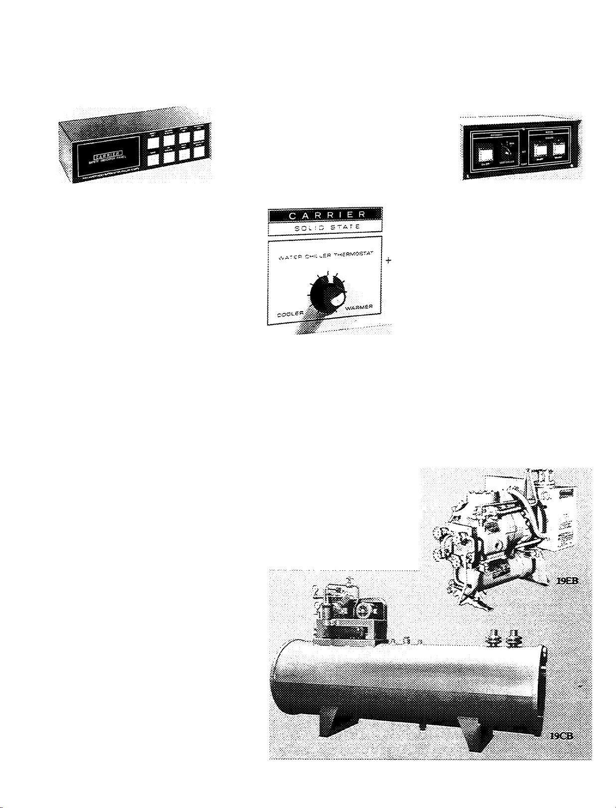
Convenience options offered for added energy-efficient, ‘tailor-made’ systems
Pneumatic capacity control
Complete pneumatic control systems
are available, if desired, for the centri
fugals in the 100 to 2000 ton (3527034 kW) sizes.
Safety indicator panel
This accessory provides the operator
with an instant trouble-shooting capa
bility. Seven panel lights monitor high
motor or bearing temperature, low
refrigerant temperature, high con
denser pressure, starter (overloads and
protective devices), low water flow
(chilled or condenser), low oil pressure,
low chilled water temperature. When
safety is tripped, the light goes on. Panel
does not affect the integrity of the
central control system, is easily con
nected to the machine without disturb
ing factory wiring. In addition, a remote
sound or light alarm can be easily field
installed to alert you, should a safety
light be tripped on the indicator panel.
Only a simple two-wire hook-up is
required.
Selective insulation
The 19 Series machines are adequately
insulated at the factory to meet most
application demands. However, addi
tional insulation packages are available
for specific machine applications.
Isolation assembly
A combination of soleplates, jacking
screws, leveling pads and neoprene
pads are available in isolation packages.
Specify this option for installations
requiring special mounting. Isolation
pads are shipped at no charge.
Remote control set point
Select or alter machine chilled water
temperature from a remote location by
specifying this optional solid state
control.
Pumpout unit
Factory mounted, complete with
starter, controls and all necessary inter
connecting refrigerant piping. Permits
easy transfer of refrigerant between
machine and storage tank. Speeds
servicing and minimizes downtime. On
multiple machine applications, a single
pumpout unit saves first costs. Not
required for R-ll units.
Lead-lag control
Desirable when two or more machines
are installed in series or parallel. Cen
tralized control features the following
capabilities;
• parallel operation
• series operation with split or common
point control
• two or more chiller operations
• uneven sized chillers working
together
• independent control of chillers both
manually and automatically
• automatic lead-lag operation
• reassignment of lead-lag hierarchy
• automatic standby
Panel lights indicate system operating
mode.
Hot gas bypass
When a machine is expected to run at
light load and elevated condensing tem
peratures or at minimum load for ex
tended periods of time, a hot gas bypass
is recommended. The hot gas bypass is
factory mounted and wired, manual or
automatic. It virtually eliminates com
pressor surging at extreme part-load
conditions and smooths out the ma
chine’s full operating cycle, whatever
the load fluctuation.
Page 10
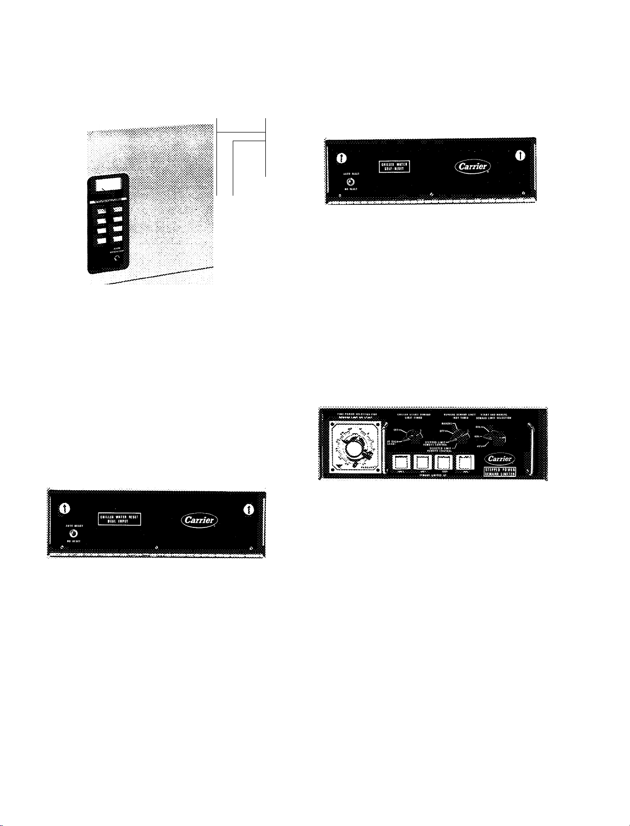
Additional energy-saving options
Chilled water self-reset control
This device permits the leaving chilled water tempera
ture to rise as the load on the machine decreases.
The higher the leaving chilled water temperatures, the
less work the compressor is forced to do.
The power monitor control
An electronic, energy-saving device which continuously
monitors building electric demand and sheds preselected
loads in stages during peak power usage periods. The
power monitor control reduces power consumption and
minimizes power demand charges.
Chilled water reset-dual input
A device that causes the leaving chilled water tempera
ture control set point to change in proportion to a change
in a remote temperature such as return chilled water or
outdoor air temperature.
Adjustable stepped-rcset control
A device that permits leaving chilled water tempera
ture to rise in predetermined adjustable steps. Operator
is in control of demand limit so amount of reset is not
dependent on machine load but on the amount of change
of resistance in the probe circuit.
Stepped power demand limiter
This option makes it possible to limit power demand in
four ways:
1. At start-up each chiller can be held to a preselected
maximum current draw for any time period of up to
one hour.
2. During normal operation, chiller load can be auto
matically reduced in up to 3 stages in response to
increased total building power consumption.
Chiller demand can semi-automatically be lowered in
3.
a single stage in response to increased total building
power consumption.
4.
Chiller demand can also be lowered manually.
Stepped power demand limiter minimizes the likeli
hood of getting demand charges. Also has timer which
increases flexibility of operator. Operator can change
demand limit without being at controls and can also
adjust demand limit manually.
#
10
Page 11
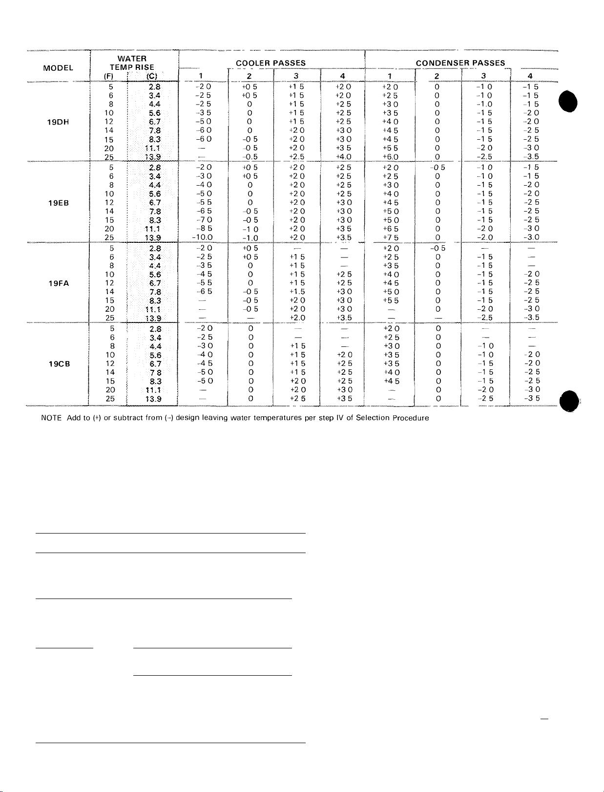
PASS-RISE TEMPERATURE ADJUSTMENT (F/C*)
*To convert the temperature adjustment factor to °C, divide by 1 8
Metric
tech
Area
cm2 100
cm3
m3 1 0
m2
Length
mm 1.0
mm 0 03937
mm 0 003281
m 1 0
m
Mass
kg
kg
Power
kcal/h 1 163
kcal/h 3 968 Btu/h 0 2931
HP metric
HP metric
Mcal/h 1 163
Mcal/h
X =
0 1550
10 76
3 281 ft
2 205
0 9863
0 3307
English
unit X =
ip2
«2
in
ft
lb
HP(550
Ton refr 3 517
645 2
0 09290
25 4
304 8
0 3048
1 0
0 4536
0 7355
0 7457
CONVERSION TABLE
SI unit
mm2
mm2
m2
m2
mm
mm
mm
m
m
kg
kg
w
w
kW
kW
kW
kW
Metric
tech
Pressure
mm w g 4°C
mm w g, 4°C
mm Hg 0°C
mm Hg 0°C
kg/cm^
kg/cm^
Temperature”
Interval
°C
y
Velocity
m/s
m/s
__
m/s _
Volume/Time
m®/h
m^/h
m^/h
L/h
__
L/h
Metric
tech
Temperature
“C
°C
0 03937
0 03937
^14 22
1 8
3.281
196.9
0 5886
4 403
4 403x10-3
Conversion
factor =
(»Cx18)+32 °F
English
unit
inHjO 39 2 F
in Hg 32“ F
psi
°F
ft/s
ft/min
fH/min
U S gal/min
U S gal/min
nEhglish
Un»
0 009806
0 2491
0 1333
3.386
98.07
6 895
1 0
0^5556
1 0
0 3048
0.00508
0 2778
0 4719
0 06309
2 778x10-“'
0 06309 _
Conversion
factor =
“C+273 15
(°F-32)-r1.8
SI unit
kPa
kPa
kPa
kPa
kPa
kPa
K
°C
m/s
m/s
m/s
Us
L7s
tVs
Us
Us
____
SI unit
K
°c
_
#
12
Page 12
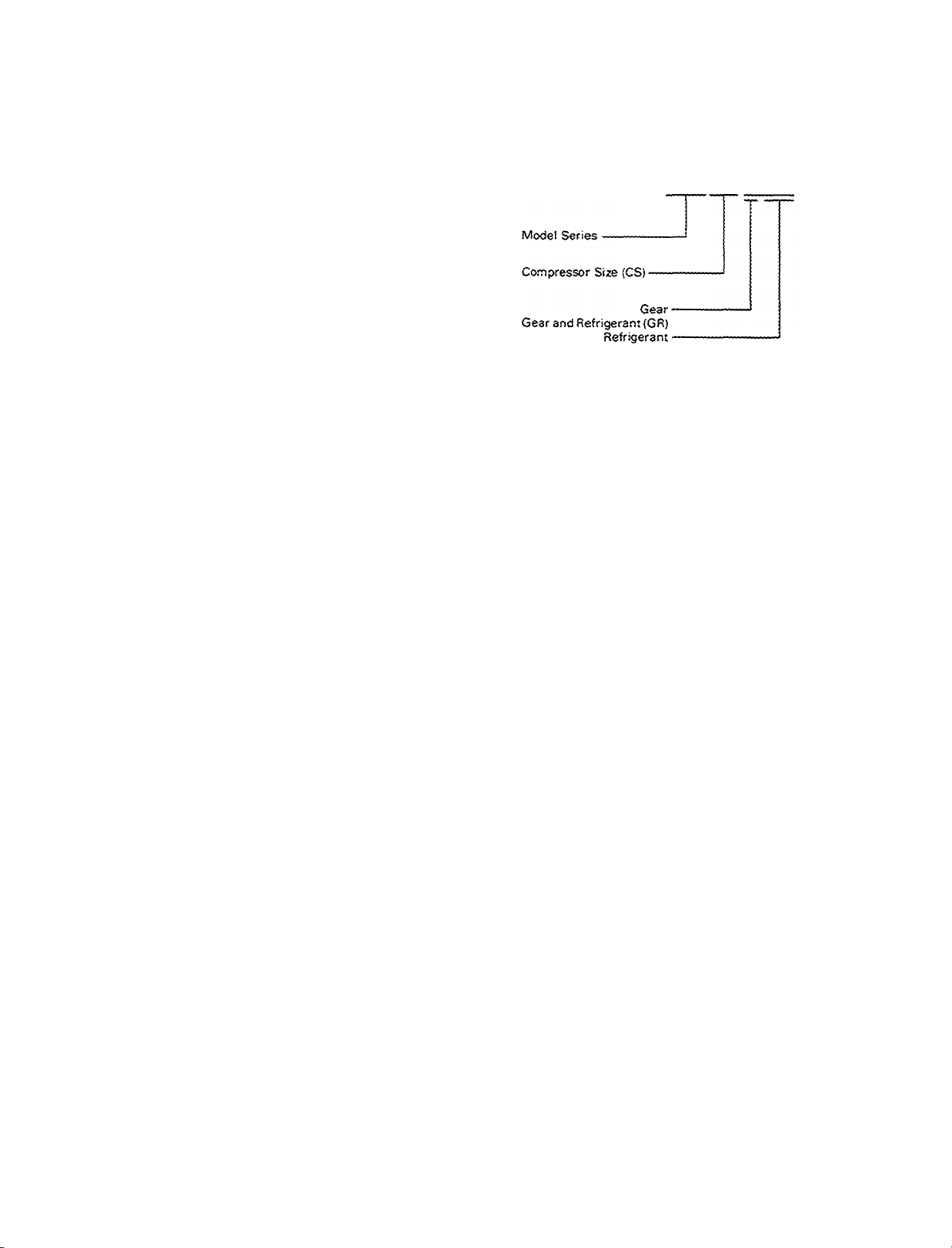
Using the 19DH,EB,CB model numbers
When ordering 19DH, 19EB or 19CB chillers, use the
ordering code described below. Chiller nozzle arrange
ment and compressor voltage must be listed separately.
Using the 19FA model number
When ordering 19FA chillers, use the ordering system
described below.
(19C8) Condenser-------------------------------------------------Heat Exchanger (HE) (UN){19CB) Cooler------------------
19EB8165DK
Model (19DH, 13EB, 19CS)-
Heat Exchanger or Unisheil (UN) •
Compressor (CS)
Motor---------------------------------------
List chiller model in first 4 code number positions
Obtain Unishell or heat exchanger size from step V of the Selec
tion Procedure and enter in positions 5 & 6
Obtain compressor size from step V of the Selection Procedure
and enter in positions 7 & 8
Obtain motor size from step VII of the Selection Procedure and
enter in positions 9 & 10
-----------------------
13FA563-B-500-2425-L-EC
Cooler -
Heat Exchangers (HE)
Condenser-
Base Size (S, small or L, large)
Motor Size (MS)-------------------------------------------------------------
1 List chiller model in first 4 code number positions
2 Obtain compressor size from step V of the Selection Procedure
and enter in positions 5, 6 and 7
3 Also from step V of the Selection Procedure, obtain gear size
and refrigerant used Enter gear size in position 8, next enter
refrigerant in 9-11 (May only need to use 9 & 10 )
4 Obtain heat exchanger size from step V of the Selection Pro
cedure and enter the cooler size in positions 12 & 13 and the
condenser size in positions 14 & 1 5
5 Base size is indicated in position 16
6 Obtain motor size from step VII of the Selection Procedure and
enter in positions 17 & 18
Part-load energy requirements
At part load, chiller energy requirements are aifected by
many variables, such as degree of load, chilled water flow,
condenser water flow, entering condenser water tempera
ture, leaving chilled water temperature, and the percentage
of compressor loading at design conditions.
Because of these many variables, a typical part-load
curve (% Standard Rating Tons versus % Standard
Rating Kw Input) may have appreciable inaccuracies
when applied to a specific chiller and set of conditions.
Carrier, therefore, does not recommend the use of
such curves in making operating cost studies.
Instead, thru computer analysis. Carrier will provide
you with accurate and detailed information on the energy
requirements for your selected chiller at the expected
jobsite conditions.
Energy savings can be significant if the chiller can be
operated with a relatively low entering condenser water
temperature. And, since conditions of design load and
design wet-bulb temperature can occur rather infrequently,
the opportunity for such savings exists during most of the
operating season. Each chiller is capable of operating
efficiently with entering condenser water temperatures
down to 55 F (13 C). This capability assures you of both
energy conservation and excellent part-load performance,
because “custom-made chillers” give the best part-load
performance.
13
Page 13
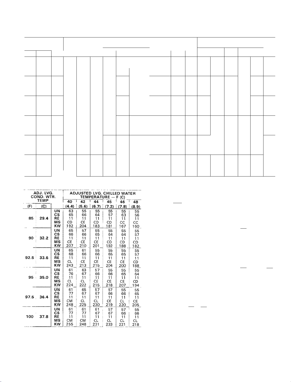
19DH Selection data
19DH*
100-450 TONS
(352-1583 kW)
100 Ton Selections (352 kW)
ADJ. LVG.
COND. WTR.
TEMP.
(F) ! (C)
1
;
85 ! 29.4
90 ; 32.2
92.5 ; 33.6
95 ; 35.0
•
97.5 ! 36.4
:
100 ! 37,8
UN 42 42 42 42
CS 13 13
RE
MS AA
KW 78 76
UN 42 42
CS
RE
MS
KW 86
UN
CS 15
RE 11
MS AA
KW 92 86 83 80
UN
CS
RE
MS AB
KW 97 92
UN 42 42
CS
RE
MS AC AB
KW 107 97
UN 42 42
CS
RE
MS
KW
125 Ton Selections (440 kW)
ADJ. LVG.
CONO. WTR.
TEMP.
(C) (4.4)
(F)
85
29.4
90
32.2
92.5
97.5 36.4 RE
95
100
33.6
35.0
37.8
UN 42
CS 27 20 13 19 12 12
RE 11 11 11 11 11 1 1
MS
KW
UN 42 42 42 42 42 42
CS
RE 11 11
MS AC AC
KW 114 107
UN 42
CS 29 22
RE 11 11
MS AD AC
KW 117 114 106 102 102
UN
CS 30 23
RE 11 11
MS AD AD AC AC
KW 125 121
UN
CS
MS AE AD
KW 136 125
UN
CS 31 24 23 23
RE 11 11
MS AE AE AD AD AD AC
KW 139
ADJUSTED LVG CHILLED WATER
TEMPERATURE — F (C)
42 ! 44 i
40
(4.4)
(5.6) ! (6.7)
11 11
AA AA AA
14 14 13 13
11 11 11 11 11
AA AA AA AA
AC
111
40
AB AB AB AA AA AA
101
r 42
83
42 42 42 42 42
14 14
11 11 11 11
AA AA
42 42 42 42 42
16 15 15 14 14
11 11 11 11 11
AA AA AA AA
17 16 15 15 15
11
11
17 17
11 11 11 11 11
AC
107
ADJUSTED LVG. CHILLED WATER
TEMPERATURE — F (C)
(6.7)
(5.6)
42
97 96
29 21 20 13
42 1
44
42
24 30 22 22
11
11
44 44
135
45
(7.2)
13 12
11 11
74
42
78 77 76
89
42 42
11 11 11
AA AA
92
42 42
16
AB AB AB
97 96
44 T 45
(7.2)
42
11
AB AB
100
42
21
1 1
AC AB
42
21
11 11
110
42 42
11 11
AD
117
42
11
125 122 116 111
46
(7.8)
* *
68
42
42
13
AA
13 13
AA AA
79
84
85
42
AA
91 89
42
16 16
95
46 48
(7.8)
42 42
88 87
13
11 11 11
AB AB
100 98 95
42 42 42
20
13
11 11 11
AB
42 42
21 14 13
11
AC
108 108 101
AC AC AC
115 114 107
42
15
11
42 42 42
22
11 11 11
48
(8.9)
*
*
*
*
*
(8.9)
42
84
13
13
AB
98
42
11
AB
42
14
11
14
150 Ton Selections (528 kW)
ADJ. LVG.
COND. WTR.
TEMP.
85
90
95
100
(C)
29.4
32.2
33.6
35.0
37.8
UN 46
CS 35 27 27 27 26 19
RE 11
MS
KW
UN 46
CS 37
RE 11 11 11 11 11
MS AE AD
KW 141
UN 50 46 46 46 46 ^ 46
CS 37 36
RE 11 11 11 11 11 11
MS AE AE
KW 142 134 127 121 119
UN
CS 37 37 35 28 28 20
RE 11 11 11 11 11 11
MS AE AE AE AE AD AD
KW 141 144
UN 50 53 46 46 46 46
CS 47 36 36 29
MS CB AE AE AE AE AD
KW 156
UN 50 50 51 50 46
CS 47 47 36 29 29
RE 11 11 11 11 11
MS CC CB AE AE AE
KW
(F)
92.5
97.5 36.4 RE 11 11 11 11
ADJUSTED LVG. CHILLED WATER
TEMPERATURE — F (C)
40 42 44
(4.4)
(5.6)
46 46
11 11
AD
AD AC AC AC AB
124
116 112 113 105 102
46 46
35
127 119
53 46 46
136 139
156
160
175 Ton Selections (615 kW)
ADJ. LVG.
COND. WTR.
(F)
85 29.4
90 32.2
92.5 33.6
95
97.5
100
LEGEND
CS — Compressor
GR — Gear-Refrigerant
HE — Heat Exchanger
KW — Power Input
MS — Motor Size
RE — Refrigerant
UN — Unishell
14
TEMP.
(C)
35.0
36.4
37.8
UN
CS 43 43 34
RE
MS
KW
UN
CS 51 44 35 35 35 34
RE 11
MS
KW 147 144 141 142
UN
CS 52 44
RE
MS CC CB
KW
UN
CS
RE
MS CC CC CB CB AE AE
KW
UN
CS 54
RE 11 11
MS CD
KW
UN
CS
RE
MS CD CD
KW
ADJUSTED LVG CHILLED WATER
TEMPERATURE — F (C)
40 1 42
(4.4)
(5.6)
50 50 51 50 50 50
11 11 11 11 11 11
AE
AE AE AE AE AD
133
138
50 50
11 11 11 11 11
CB
CB AE
50 50
11 11
156
150
50 50 50
53 52 44
11 11 11
166 156
50 50 50 50 50
46 45 45 44 34
CC CC
183 169 157 155
50 50
54
47 46 45
11 11 11 11
189 186
(6.7)
(6.7) (7.2)
45
(7.2)
44 44
11
46
27 27 20
AD
AD AD
117 115
27 27
28
AD
AD AD AD
46
130 128 127 119
136
138
139
44
45
34
130
130
143
148
168
51 50
53
AE
50
44
11
AE AE AE
CB
143
11
146 144
11
11
CB
50
CC CC
160
53 51
35
11
50
44
50
r 48
46
(7,8) (8.9)
11 11
46 46
46
28
11 11
130 122
138
46 48
(8.9)
(7.8)
34 26
128 116
AE AE
141 131
35 34
11
142
53 51
35 34
11 11
11 11
CB AE
148 140
50 I 50
45 45
11 11
CC CB
157 153
44
19
11
AC
105
20
115
46
27
46
28
11
AE
129
11
136
138
#
50
50
53
Page 14
200 Ton Selections (703 kW)
ADJ. LVG
COND. WTR.
TEMP.
(C> (4.4)
(F)
85
29.4
90
32.2
92.5 33.6
95
35.0
97.5 36.4
100
37.8
UN 51
CS
RE 11 11
MS
KW
UN
CS
RE
MS CC
KW 166
UN
CS 59
RE
MS CD
KW 176
UN
CS 60 52
RE
MS CD
KW
UN
CS 61
RE
MS
KW
UN
CS
RE 11 11
MS
KW
A
DJUSTED LVG.
TEMPERAT
" 42 “I 44
¡5.6) ; (6.7)
51 51
57
50
CB
CB AE
156 151
53 51 51 51
58 51
11 11
CC
164 155
53 51
58 51 50
11 11
CC CC
170 164 156
53
53 51"’ 51
11
11 11 11
CD CC
188 175 171
53 53
59 51 51
11 11 11
CE CD
207 181 171
53 53
61
60
CE CD
215 193
CHILLED WATER
JRE — F (C)
49 49 42
11
140 136
50
11
CB CB
51 51
11 11
51 51
53 53
CC
53 53
52
11
CD
181 177 171
45
(7.2)
51
11 11
AE
50
11
152
CC
CC
167 164
11
CC CC CC
168 169
52
11 11
CD CC
46
(7.8)
(8.9)
51
AE
136
51
43 42
11
CB AE
152
141
51 51
43
11 11
CC CB
156 151
51
51
11
CC CC
156
51 51
51 44
11 11
166
53 51
51 51
CC
169
275 Ton Selections (%7 kW)
ADJ. LVG.
COND. WTR.
48
51
42 CS
11
AE MS CE
51 UN
11 90
43
51
43
11 95
1 1 100
TEMP.
(F) (C)
85
29.4
32.2
92.5
33.6
35.0
97.5 36.4
37.8
40
(4.4)
UN 61
RE 11
KW
203 197
61 61 65
CS 81
RE
11
CL
MS
KW
219
UN 61
CS 82
RE 11
MS CL CL
KW
233 222
UN 61
CS
RE
11 11
MS CM CL
KW
248 236 221
UN 61
CS
RE 11
MS CN
KW 276
UN
61 61
CS 84
RE
11 11 11
MS CN CN
KW 281
ADJUSTED LVG. CHILLED WA1
TEMPERATURE — F (C)
42
44
(5.6)
(6.7)45(7.2)
61
73
CD CD
CE
210
63 61
73 64 64
11 11
73
11
61
74
11
CD
195
196 178 171
65
11
CE
CL
210
223 202
65
66
11 11
CL CL
11
61
66 64
11 11 11
63 61 61
66 65 64
224 224
83
^ 61 61
75 74
CL CE
11 11
65 61 61
65 67 64
219 241
77 76
11 11
CM CL
251 236
77 76
276 250
6Ì 61
CM CM
61
75 75
11 11 11
CL CL
232 234
61 61
11
246
76
■ ER
48
46
(7.8)
(8.9)
61 61
63
11 11
CD CD
61 61
CE CD
184
11 11
CE
CE
217 201
11 11
CL
CE
208
63 61
66
CL
222
65 61
66 66
11 11
CL
CL
236 236
56
63
65
250 Ton Selections (879 kW)
300 Ton Selections (1055 kW)
ADJ. LVG.
CONO WTR
TEMP.
(F) (C)
85 29.4
90 32.2
92 5 33.6
95 35.0
97 5 36.4
100 37.8
UN
CS
RE
MS
KW.
un'
CS
RE
MS
KW
UN
CS
RE
MS
KW
UIM^
CS
RE
MS
K^
UN
CS
RE
MS
KW
UN
CS
RE
MS
KW
ADJUSTED LVG. CHILLED WATER
40
(4.4Ì
61
80
11
CL
223
61
82
11
CM
252
61
83
11
CN
267
61
90
11
CN
274
éf
84
11
CP
306
63
84
11
CP
307
TEMPERATURE — F JC)
44 "T
42
¡5.6)
61
73
11
CL
219
61
81
11
CL
236
’ 61 ’
81
11
CM
243
61
82
11
CM
259^
61
83
11
CN
274
61
84
11
CP
303
211
(6.7) :
61
73
11
CE
61
73
11
CL
225
6l’
74
11
CL
240
éi"
75
11
CM
255
61
82
11
CM
258
61
83
11
CN
273
45
¡7.2)
61
72
11
CD
197
61
73
11
CL
2M
"'61
73
11
CL
228
61 ’
74
11
CM
242
61
75
11
CM
259
61
76
11
CN
274
46
(7.8)
61
72
11
CD
.1?3
61
73
11
CE
.217„
6Ì"
73
11
CL
224
6l"
74
11
CL
238
61
74
11
CM
246
61
75
11
CM
262
48
63
63
11
CD
189
65
64
11
CE
212
65
64
11
CE
218
73
11
CL
223
61
74
11
CL
238
61
75
11
CM
252
*For additional tonnage and performance selections contact your nearest Carrier Sales Office (see page 50)
15
Page 15
19DH Selection data (cont)
350 Ton Selections (1231 kW) 400 Ton Selections (1407 kW)
ADJ. LVG.
CONO. WTR.
TEMP.
(fT
92.5
97 5 36.4
100
(C) (4.4)
85
29.4
90
32.2
33.6
95
35.0
37.8
UIM
CS 95
RE 11
MS
KW 271
UN 63
CS
RE
MS CP
KW
UN 65
CS 97
RE
MS CP
KW 311
UN 65
CS
RE 11
MS CQ
KW 344
UN 65
CS 98
RE 11
MS CQ
KW 352
UN
CS 98
RE
MS
KW
LEGEND
CS — Compressor
GR - Gear-Refrigerant
HE — Heat Exchanger
ADJUSTED LVG. CHILLED WATER
_ JTEMPERATURE — F (C)
42 44
40
(5.6) (6.7)
63
63
87
CN CM CM CL CL
11 11
255 247
gg
95
97
11
11
CN CM
279 263 259
309
CQ
358
63
96
11 11
11
CP CN
297
63
97 89
98
11 11
CP
317
65 63
97 90
11 11
CP CP
319 316
65
72
91
11 11 11 11 11 11
CQ CP
352 318 321 305
KW — Power Input
MS — Motor Size
RE — Refrigerant
UN — Unishell
45 46
(7.2) (7.8)
63 63 63
80 86
229 225
63 63 63
87
11 11 11 11 90
CM
63 63
88 87 80 80
CN
278 265
63 63 63 63
CP CN CN CM
296 282 276 261
CP
300
65 63 63 63
90 90
CP
79 72 CS
11
11
80
80
CM CM
254
63
11
11
CM
264
88 81 80
11
11
63
63
82
89
11
11
CN CN
294
89
CP CN
ADJ. LVG.
COND. WTR.
48
(8.9)
63 UN
11 85 23.4 RE
CL
220
63
73 CS
249 KW 335 339 309 294
63
11
CM
252
11
63
81
11
276 KW
82 CS 97 97 97 89
295 KW
TEMP.
95
(C>
32.2
35.0
36.4 RE
37.8
(F)
92.5 33.6
97.5
100
MS
KW
UN
RE 11 11
MS
UN
CS
RE
MS
KW
UN
CS 97 97 96 95 87
RE
MS CQ CQ
KW 348 350 333 318 297
UN 77
CS
MS
UN
RE
MS CQ CQ CQ
ADJUSTED LVG. CHILLED WATER
TEMPERATURE — F (C)
40 142 44 45
(4.4)
(5.6) (6.7)
76 71
95 95 94 87 86
11
CP CP CN CN CM CM
298
CQ CQ CP CN CN CN
CQ CQ CQ CP CP CN
338 344
11
301
77 72
97 97
78 73 71
97
97 96 95
1 1
11 11 11 11 11
76
*
11 11 11 11
97
*
11 11 11 11 11
CQ
353
*
*
(7.2)
71
71
11
11
279 275 256
326 313 299 286
CQ
71
71
94
95
11
11
71
71
71
CQ
71
73
97 96
97
CQ
356
352
76 73 72
11 11 11 11
357
358
46 48
(7.8)
(8.9)
71
11 11
71
87 80
11 11
281
288
71
94
71
CP
71
CQ
338 317
356
71
79
247
71
71
87
71
11
CP
71
88
CP
71
CQ
334
UNISHELL COOLER
FLOW RATE L/s
.2
2 4
FLOW RATE. GPM (lOO's)
100;
50
- 100
- 50
iOO
UNISHELL CONDENSER
- 100
50
.2
- 100
-* 0
100
50
16
50
-* 0
Page 16

UNISHELL COOLER
FLOW RATE L/s
2 4
UNISHELL CONDENSER
4 8
FLOW RATE.GPM (lOO's)
- \00d
50 ^
100
50
50
-* 0
40
30
20
10
- 100
50
0
0
-1--^--.
---
r
- 100
50
0
-]—r
/3f
%ss
2 PA 3S
53 CONDENSER
IP ^SS
100
I
100
50
100
50
100
50
- 50
8 1 0
- 100
50
100
50
12
20
17
Page 17

19DH Selection data (cont)
0 10
UNISHELL COOLER
FLOW RATE L/s
5 1.0
FLOW RATE, GPM (lOO's)
10
UNISHELL CONDENSER
Û.
I00c5
CL
o
cn
Q
50 y
ctr
3
(/)
cn
iU
20
I 5
- 100
50
20
i 5 I 0
10
100
20
100
20
I 5
100
10 20
20
1 0
20 30
1 5
50
- 100
50
100
10
20
50
20
1 5
100
50
20
I 5
-I 0
30
15
I 0
100
50
20
30
18
20 30
t
Page 18

UNISHELL COOLER
FLOW RATE L/s
10 15
UNISHELL CONDENSER
0 5 10 15
20
100
50
I
1
19DH
UNISHELL
SIZE
42
44
46 8,600
50 10,000
51
53 10,400 47’lT
55
57
61
63 14,200 6441
65
71 15,800 7167
72
73
76 16,800
77
78
RIGGING
WEIGHT
(lb)
8,400
8,500
10,200
10,600
10,800
13,900 6305
14,400 6532
16,000 7257 18,175 8244
16,300
17,200
17,500
10 20 30
FLOW RATE.GPM (lOO's)
10 15 2 0
10
30 40
Physical data
OPER
WEIGHT
(kg)
(lb) : (kg)
9,260 14200
3810
9,405 14265
3856
9,570:4341
3901
11,105 :5037
4536
11,335 15141
4627
11,600: 5262
4808 11,860; 5380
4899
12,115 15495 625 : 283
15,660:7103 775:352
16,040:7276
16,370,7425
17,91518126 975■442
7394
18,560:8419
7620 19,30018754
7802
19,870:9013 1150'522
7938
20,330:9222 1200 544
CHARGE
(lb) :(kg) (sq ft)
500:227
525:238
550:249
575:261 130
5751261
600 1272 130
625:283 130
810:367
850:386 213
985'447
1010 458
1100:499 218
OPER
R-11
0 Q-
- 100
50
AREA
TO
INSULATE
(m^)
130
12
130 12
130
12
12
130
12
12
12
130
12
213
20
213
20
20
218
20
218
20
218
20
20
218
20
218
20
10 15 20 25
10
Elcctriccd data
MAX
MTR
AA
_
AB LRA Star
AC
AD
AE
CA
CB
CC 172 LRA Star
CD
CE
CL
CM
CN
CP 323 LRA Star
CQ 360 LRA Star 1789
FLA — Full Load Amps
KW — Compressor Power Input (Kilowatts)
LRA — Locked Rotor Amps
WITR — Motor
NOTE Overload Trip Amps = FLA x 1 08
19
VOLTS
KW
FLA per Kw
LRA Star
93
LRA Delta
FLA per Kw
105
LRA Delta
FLA per Kw
115 LRA Star
LRA Delta
FLA per Kw
129 LRA Star
LRA Delta
FLA per Kw
144 LRA Star
LRA Delta
FLA per Kw
144
LRA Star
LRA Delta
FLA per Kw 3^04
1 56
LRA Star
LRA Delta
FLA per Kw
LRA Delta
FLA per Kw
200
LRA Star
LRA Delta
FLA per Kw
219
LRA Star
LRA Delta
FLA per Kw
243 LRA Star
LRA Delta
FLA per Kw
267 LRA Star
LRA Delta
FLA per Kw
295 LRA Star
LRA Delta 4652
FLA per Kw 3.04
LRA Delta
FLA per Kw 3.04
LRA Delta
20
30
20 30 40
208 230
3 08
2 78
439
370
1378 [115^ 577
2 78 1 39
3 08
402 201
480
1254
1500
3 08' 2.78
528 442 221
1648
1380 690 552 — —
3 08
2 78 1 39 1 12
576
482
1800
1506 753 602
3 08
2.78 1 39 1.12
653 546
2040 1706
_
_
_ _
— —
2 75'
776 650
2425 2032
3 04
2.75 1.38
862 722
2256
2695
3 04
2 75
1008
844
3150
2636 1318
З' 04
2 75 1 38
1082
908
3382
2836 1418
3 04 2 75 1.38 1 10
1219
1020 510 408
3186
3810
3 04 2 75
1336 1124 562
3514
4180
3.04 2 75 1 38 1.10
1490 1246 623 497
3888
2 75 1 38 1.10 263
1603
1340
5010 4190
2 75 1.38 1 10 264'^ 153
1502 751 599
5595
4690 2345
" "Г"""
460 j575
1 39
1 12
185
148
462
1 12
161
627
502
1 39 1 12
177
241 192
273 218
853 682
_
_
1 38" 1 10
325
260
1016 813
1 10 262
361
289
1128
903 226
1.38 1 10 265
422
337
1053 265 153
1 10
454
363
1132
1593 1273 320 185
1.10 266
1.38
450
1757 1405 353 204
1944 1554
670 536
2095 1674 421
1874 474
2400
4160
— —
--
__
—
— —
— —
_
— —
—
_ _
—
_
_ _
_
271
187
263 154'
— —
204
_
— —
264
—
284 164
263
— —
.155
— —
264
— —
392 226
.152
— —
— —
100
— _
—
_
_
—
_
_
160
108
118
151
_
130
150
151
_
152
153
243
273
Page 19

19EB Selection data
19EB*
425-1100 TONS
(1495-3870 kW)
450 Ton Selections (1583 kW)
ADJ. LVG
COND WT
TEMP.
Ft.
(F) ; (c>
>"UN 71 71 71 71 71 71
29.4 RE 12 12 12 12 12
85
90 32.2
92.5
33.6 RE
95
35.0
97 5 36.4 RE 12 12 12 12
100
37.8
cs 23
MS
KW 336
UN 71 71 7Ì 71 71
CS
RE 12
MS DC
KW 363 348
UN 71 71
CS
MS
KW 372 360
UN
CS 25
RE 12
MS
KW
UN 71 71
CS 35
MS
KW
UN 71 71
CS
RE
MS
KW
ADJUSTE
4Q I 42
(4.4) i {5.6)
DB
23 23 21
33 23
12
DC DB DB DB
71
DD
396
DD
412 394
27 35
12 12
DE DD
434
500 Ton Selections (1759 kW)
ADJ. LVG. T
CONO WTR. i
TEMP.
(F)
85 29.4
90
32.2
92.5
33.6
95
35.0
97.5
36.4 RE 12 12
100
37.8 RE 12 12
..
_____
(C)
UN
CS
RE 12 12
MS
KW 356 342
UN
CS 33 33
RE 12 12
MS
KW 387 381
UN 73 73
CS
RE 12
MS
KW
UN 73 73
CS
RE 12 12 12
MS
KW 425 403
UN 73 73
CS 35 35
MS DE DE
KW 440 429 406
UN 73 73
CS 37 35
MS DE DE
KW
ADJUSTED LVG CHILLED WATER
40
(4.4)
73
31
DB DB
73
DD DC DB DB
33 33
DD
404
35 33
DE DD
468
D LVG. CHILLED WATER
TEM
PERATURE — F (C)
44
^T 45 T 46 ¡'48'’
{6.7) i (7.2) = (7.8) i (8.9)
21 21 21 21
DB
DB DB DB DB
314
306 303 299 292
12
DB
DB
328
12
350
71
25
12
DC DB
384
359
^71 71
25
DD
DC DC DB
371 366
DD
396 393
416
TEMPERATURE — F (C)
.
....................
42 44
(6.7)
Ì5.6)
73
31
DB DB DB
336 329
73
356 363
12
DD
DC DC DC
390 366
DD DD DD
395 388
DD
442
433
21
12 12 12 12
DB DB
320 317
71 71
71
23 21 21
23
12 12 12 12
347 327
71 71
23 23 23 21
12
12
DB DB
357
23 23
71 71 71
25
25
12 12 12
DD
(7.2)
73 73
21 21 21
12 12
73 73
21
31
12 12
73 73 72
31 23
12 12
377
73 73 72
33 23
12
73
73
33 33 33
12 12
DD
402
73 73 72
25 33
12 12
DE DD DD
416
41 6
21
DB
7Ì
12 12
354 329
71
23 23
12 12
363 357
23 23
DC
375 366
46
(7.8) ¡8.9)
72 72
12 12
329 322
72 72
21 21
1 2 12
DB
360 341
23
12
377
23
12 12
388 366
72
12
DD
403
33 23
12 12
DB
310
DB
320
DB
DB
DC
48
DB
DB
DB
354
DC
DD
389
DD
402
11
12
71
21
71
71
71
71
21
21
31
72
23
12
12
72
12
72
72
550 Ton Selections (1934 kW)
ADJ. LVG.
COND WTR.
TEMP.
(F) (C) i (4.4) (5.6) (6.7)
29.4
85
90
32.2 RE 12 12
92.5
33.6
95
35.0 RE 12 12
97.5 36.4
100
37.8 RE 12 12
UN
CS
RE 12 12
MS
KW
UN
CS 43 33
MS
KW 434 419
UN
CS
RE
MS
KW 459 432
UN
CS 45 35
MS
KW 475 458
UN 73 73
CS 47 45
RE 12
MS DG
KW
UN 73 73
CS 47 37
MS
KW 524 505
ADJUSTED LVG. CHILLED WATER
TEMPERATURE —
'42'"' ''44'“^
40
73 73
31
43
DD DD
409 393
73 73
DE DE
73
45
12
DE DE
73 73
DF DF
508
DH DG
DD DC DB
398
DD DD
409
73
43
12
DE DD DD
DE DE DE
435 425
12
DF
477
475
600 Ton Selections (2110 kW)
ADJUSTED LVG. CHILLED WATER
TEMPERATURE — F (C)
42
40
(4.4)
(5.6) (6.7)
76 76
DE DE
12
76 76
45 43
76 76
45 45
523 495
76
DH
47 47
DJ DH
DD DD
415
401 395 387
76
12
DE DE DE
451 445
76
DG
DG DF DF
DG DG DG
547_
20
ADJ LVG.
COND. WTR
TEMP.
(F)
85
90
92.5
95
97.5 36.4
100
LEGEND
cs
Compressor
GR
Gear-Refrigerant
HE
Heat Exchanger
KW
Power Input
Motor Size
MS
RE
Refrigerant
UN
Unishell
(C)
UN
29.4
32.2 RE
33.6 RE 12 12
35.0 RE 12 12
37.8
CS 43 41
RE 12 12
MS
KW 436
UN 76
CS 37 43
MS DG DF
KW 501 449
UN
CS
MS DG DF
KW 494 472
UN
CS
MS DG DG
KW
UN
CS 47 45
RE 12 12
MS
KW 544 513
UN 76 76
CS
RE 12 12
MS
KW 572
F (C)
45
(7.2) (7.8)
73 73
23 31
12 12
364
73 73 73
33 31 31
12 12
393 383
73 73
33 33 31
12 12
418 416
73 73 73
33 33 33
12 12
73 73
35
12
DF DF
460 442
73 73 73
35 35 33
12 12
DF DF DF
468 448 434
44
(7.2)
76 76
25 31
12 12
76 76
41 33 31
12 12
428 431
76 76
43 33
12 12
DF DF DE
76 76
43 43
12
DF DF DF
465 458
76 76
35 43
12
499 475
76 76
45 45
12 12
512 507
360
DC
399 384
420 397
33 33
12
DE DE
432 423
45 46
(7.8)
DC DC
423 405
439 425
12
453 444
12
466 459
484 482
46
31
31 31
48
(8.9)
73
73
31
12
12
DB
353
73
31
12
12
DC
373
73
73
31
12 12
DC
73
31
12 12
DD
73 73
33
12 12
73
33
12 12
DE
48
(8,9)
76
75
12 12
381
76 75
31
12 12
DD
76 75
33 31
12 12
DE
76 75
33 33
12 12
DF
76 75
43 33
12 12
DF
76 75
43 33
12 12
DG
Page 20

650 Ton Selections (2286 kW)
ADJ. LVG.
CONO. WTR
TEMP.
(F)
85
29.4
90
32.2
92 5
33.6
95
35.0
36.4
97.5
100
37.8
<C) (4.4) S (5.5)
UN 81
CS 43
RE
MS
KW 482
UN 81 77
CS
RE
MS DG DG
KW 520 506
UN 81 77
CS
RE
MS
KW 549
UN 81
CS 47 45
RE
MS
KW
UN
CS 47 47
RE
MS
KW 584
UN 81
CS
RE
MS
KW 599 587
ADJUSTED LVG. CHILLED WATER
_ TEMPERATURE — F (C)
(6.7) 1 (7.2)
12
DG DF
461
45
12
47 45
12 1 2
DH
DH
523
12 12
DJ DH
571
556 521
82
12
DJ
DJ DH
578 541
65 47
12 12
DK DJ
77 77
43 33 41
12
DF
464 425
45
12
DF DF
476 467
DG
498 j_483
77
DH
77 77
12 12
81 77
DJ DH
573
77 77
12
12 12
DE DE
77
77
43 43 41
12 1 2
77
77 77
43
43
12
12
DG DF
77 77
45
43
12
12
DG
510 492
77
45 37
12
DH
560
77
45 45
12
12
550
750 Ton Selections (2638 kW)
ADJ. LVG.
COND. WTR.
TEMP.
(7.8) (8.9) (F)
416 412
DF
456
476
DG
DG
520 492
DH
540
77
41
31
12
DD
77
77 UN
41
12
12
DE
431
77
43 41
12 12
DF
446 KW 61
77
77 UN
43
33
12 12
DG
483
77 77
43 43
12
12
DG MS DL
77
77 UN
45
43 CS
12 12
DG
510
85
90
92 5
95
97.5
100
29.4
32.2 RE
33.6 RE
35.0 RE
36.4 RE
37.8 RE
(C)
: ¡4.4)
UN
CS
CS
CS
CS
MS DK
KW
UN
CS
KW
MS DM DL DL
KW
82
RE
500
MS DH
KW
554
12
MS DJ
KW
587
UN
82
73
12
MS DK
82
73
12 12 12
630
82 82 82
65 73 63
12 12 1 2
665 637 604
82 82 82
67
12
708 661 644
ADJUSTED LVG. CHILLED WATER
TEMPERATURE — F (C)
(6.7)
(5.6)
82 82 82
47
39
500
DH DH DH
554 550 536
82
" 82
63 49 47
500 500
DJ DH DJ
591
82 82 82
63
12
DJ DJ
1
588 563 553
82
63
DK DJ
605 591 586
DK DK
65 65
12 12
(7.2)
45
12 12
82 82
12
542
578
47
500 500
DH DJ
82
63
63
1 2
DJ DJ
63
12
DK
597
12 1 2
DK
616
(7.8) (8.9)
82
45
43 43
12
DG
513
82
45
45
12
DH DH
559 521
82
47
45
12
578
82
82
47
500
564
82
82
63
12
DK DJ
592
82
..
82 82
63 63
DK
608
DG
488
DH
550
DJ
574
594
DK
599
82
12
82
43
12
82
43
12
82
45
12
82
45
12
63
12
m
700 Ton Selections
ADJ. LVG
COND. WTR
TEMP.
(F)
; (C)
85
i 29.4
90
32.2
92.5
33.6
;
95
: 35.0 RE
97 5
i 36.4
100
i
37.8
UN 81 81
CS
RE
MS
KW 570
UN 82
CS 49 47
RE
MS
KW
UN 81
CS
RE
MS
KW
UN 81
CS 65
MS
KW
UKT 81 81
CS 65 65
RE
MS
KW 622
UN 81
CS
RE
MS
KW
ADJUSTED LVG CHILLED WATER
1^5 1 42
1
(4.4)
(5.6) i (6.77
47
12
DJ
500
DJ
565 575
63
12
DJ DJ
570 597 552
12
DK DJ
603
12 12
DK
67
12 12
DL
673
TEMPERATURE — F (C)
4Q
(7.2)
81 81
45
43 43 41
12 1 2
DG DG DF
520 485
81 si
12
DJ
DH
530 517
81 81
47
12
DH
81 81 81
63 47 45
12
571 587
DJ
DK DJ
610 577
81 81
65 65
DK
DK DJ
628 617
12
475
81
45
43
12 1 2
DG
81
45 45
12 12
DH
539
12
12
DH
560 547
81 81
63 45
12
12
DJ
589
81
63
12 12
590
(7.8)
(8.9)
81
12
DF
DE
463 434
81
43 41
12
DG DF
498
478
81
43 43
12
DG DG
523 496
81
45
12
DH
DG
514
81 81
45
12
DJ
DH
566
534
81
45 45
12
DJ
DJ
577
564
800 Ton Selections (2814 kW)
ADJ LVG
COND WTR
TEMP.
81
41
12
81 UN
12
81
2
81 UN
43
12
43
12
81
12
(F) 1 (C)
85 : 29.4
90 i 32.2 RE
92.5 i 33.6 RE
95 : 35.0
97 5 i 36.4 RE
100 i 37.8 RE
UN 87 82 82
CS 47
RE
MS DJ DJ DH
KW 580
CS 71 71 71
MS
KW
UN
CS 73
MS DK
KW
CS
RE
MS
KW 644 647 633 607 600 590
UN
CS 75 65 73 63 63
MS
KW 692 694
UN
CS 75 75 73
MS
KW
ADJUSTEI
"40~1 42
(4.4) 1 (5.6)
500
85
12
DJ
590 592 579 585
85 82
12 12 12 1 2
632
^85 "
73 73 63 71 71 47
12 12 12 1 2 12
DL
85 82 82 82 82 82
12 1 2 12 1 2 12 1 2
DM DM DL
85
12 1 2
DM DM DL
71 1
0 LVG. CHILLE
CERATURE —
TEM
500
589
—82~
DJ DJ DJ
DK
635
DL
44 1
'45
(6.7)
__
47 45
500
547
82
12
12
82 82
71 71
73
DK DJ
593 592
82 82 82
DK
654 641 632 597
82 82 82 82
82
12 1 2 12 1 2
714 675 669
D WATER
F(C)
46 1 48 ^
(7.8) I (8.9)
(7.2
500
DH
522
500 500
DK DK
DL DK DK
DL DL DK
45 45
500 500
DG DG
512
82
47
DJ
567
500
DJ DH
597
73
654
82 82
82 82
47 45
82
47
82 82
63 63
43
478
500
DH
530
82
45
500
557
500
DJ
61
635
*For additional tonnage and performance selections contact your nearest Carrier Sales Office (see page 50)
21
Page 21

19EB Selection data
(cont)
850 Ton Selections (2989 kW)
ADJ LVG.
CONO WTR.
TEMP.
(F) i (C)
UN
85 29.4 RE
CS 71
MS
KW
UN
90 : 32.2 RE 12
CS
MS DL
KW 643
UN
CS
92.5 : 33.6
95 ; 35.0 RE 12
RE
MS DL
KW
UN
CS
MS DL
KW 686
UN
97.5 i 36.4 RE 12
100 i 37.8
CS
MS DM DL
KW 728
UN 85
CS
RE 12
MS DN DM
KW
ADJUSTED LVG. CHILLED WATER
r 40
(4.4)
661
TEMPERATURE —
42
(5.6)
85
85
71 47 47
12 12
DJ DJ
588
575 592 574
85
85
73
71 71 71
12
DK
603 592
85 85
73 71 71
12
12 12 12
DK
625 610 606
85
85
73
73
12
DL
667
85
85 85 85
75 73
12
687
85
75
75 73 73
12
748 736
44
45
(6.7) (7.2)
83
83
500 500
DJ DJ
85 85
12 12
DJ
DK
591 594 577
85 85
71
DK
DK
85 85 85
71
71
12 12
DK
DK
631
622
73 73
12 12
DL DL
675 669 636
85 85
12 12
DL
DM
688 682 646
690
1000 Ton Selections (3517 kW)
F(C)
48
46
(8.9)
(7.8)
83 83
45
500 500
DH
551
500 500 90 ; 32.2 RE 500 12
DJ DJ
DK DJ
598 589
DK DK
617
DK DK
DL DL
43 CS 75
DH
522 KW 686
85 83
47 45
85 85
71 45
12
500
83
71 71
12 12
613
85 83
71 71
12 12
631
85 85
73 71
12
12
ADJ. LVG.
COND WTR.
TEMP.
(F) < (C) (4.4)
UN 89
85 i 29.4 RE 500 12
MS
UN
CS 77
MS
KW 769 709 685
UN 89
92.5 ; 33.6 RE 500 12 12
95 ; 35.0 RE
97.5 i 36.4 RE
100 ; 37.8
CS 79
MS
KW 851
UN 89 89 87
CS
MS
KW
UN 89 89 87
CS
MS DP
KW 804 777
UN 89 89 87 "
CS 85 83
RE
MS DP DN DN
KW 850
ADJUSTED LVG.
40
DL
89 89
DN DM DL DL
DP
*
*
*
TEMPERATURE —
42
(5.6)
89
81
DL
661 639 639 637
81
89
83 81 81
DN
751
83
12 12
DN
773
83 83
12
12
CHILLED WATER
44 I 45 ! 46 ^
(6.7)
(7.2) (7.8) (8.9)
sF*
87 87
71 71
12
DL
DM
703
DN
752
DN
804
12 12 12
DL
89
87
81
81
12
12 12 12
685 672 654
89
87 87
12 12
DM DM DL
702
73
81
12 12 12
DM
730
83 73 71
12
12
DN
777 764
83 83 73
12
12 12 12
803
F (C)
71
DK DK
87 87
71 71
DL
81 71
694
87 87
81 71
DM DM
716 694
87
12
DN DM
...
87 ' 87
DN
792 766
48
87
71
624
DL
87
12
674
12
729
DN
900 Ton Selections (3165 kW)
ADJ. LVG.
COND. WTR.
TEMP.
(F) i (C)
UN 85
85 ; 29.4 RE
90 : 32.2
CS
MS
KW 626 604
UN 85 85 85 85
CS 73 71
RE 12 12
MS
KW 684 649
UN 85 85
92.5 ; 33.6 RE 12 12 12 12
95 : 35.0 RE
j
_
_____i______
;
97.5 ! 36.4 RE
j
100 ; 37.8
CS 83 73 71 71
MS
KW 708 686
UN 85 85
CS 75 73
MS
KW
1
UN 85
CS
MS
KW
UN 85 85
CS
RE 12 12
MS
KW 834
ADJUSTED LVG. CHILLED WATER
TEMPERATURE -
40 42
(4.4)
(5.6) (6.7) (7.2) (7.8) (8.9)
81 71 71 71
12 12
DK
DL DL
DM
12 12
DN
747
703 691 657 642 637
75 73
12
DN
774
735
77
DP
773 734 719 714 673
44
45 1 46 48
85 85 85 85 83
12 12
DK DJ
DL DL DK
DM DL DL DL DK
85 85 85 85 85
12 12
DM
75
DN DM DM DM DL
DJ
595 588 587
71
71
12
12
DK DK DK DK
619
626
643
DM
707 701 712 649
85
85
73
12
73
85
73
12
85
637
85
71
73
DM
12
12
85
73
12
1100 Ton Selections (3869
F(C)
45
25
500
500
DJ DJ
582
85
85
71 71
12 12
613 600 KW
85 85
71
71
12
12
DK
DK
631 618
85 85
71
71
12 12
71
83
12 12
DL
DM
85 85
71
73
12
12
ADJ LVG.
COND. WTR.
TEMP.
(F) ; (C) (4.4)
85 : 29.4 RE
90 ; 32.2 RE
92.5 : 33.6 RE
95 i 35.0 RE
I
97.5 ; 38.4 RE
100 37.8 RE
UN
CS
MS
KW
UN
CS
MS
UN
CS
MS
KW
UN
CS
MS
KW
UN
CS
MS
KW
UN
CS
MS
KW
ADJUSTED LVG. CHILLED WATER
TEMPERATURE —
40
42
(5.6) (6.7)
* *
*•
* *
*
*
*
* *
* *
*
*
*
44 r
*
*
*
45
F(C)
46
(7.2)
(7.8) (8.9)
89
89
73 81 71
500
DL
680 693 676
500
DN
748 739
500
DN
776 772 740
12
DM DL
89 89 89
75
81 81
12
DM DM
89 89
75 81
12 12
DN DM
89
73 81
*
12 12
DP DN
839 762
89 89
77 81
*
500 12
DP
862
*
48
89
12
12
718
89
81
89
DN
802
89
83
*
12
DP
842
LEGEND
CS — Compressor
GR — Gear-Refrigerant
HE — Heat Exchanger
KW — Power Input
MS — Motor Size
UN
Refrigerant
Unishell
RE
22
Page 22

UNISHELL COOLER
UNISHELL CONDENSER
10 20
FLOW RATE, GPM (lOO's)
10
I 0
20
10
lOOo
q:
a
Hi
50 g
(/)
UJ
-* 0 o10
15
10 15
20
1 5
100
50
-■ 0
30
20
100
50
- 100
10
20
15 2 0
30
50
100
10
10
20
20
1 5 2 0
1 5 2 0
50
-* 0
10
20 30
I 5 20
100
- 50
30
10
20
30
I 0 1 5
100
50
50
0
100
50
25
100
50
0
10
20 30 40
20 25
m
10
20
- 100
30
23
10
20 30
40
100
50
0
Page 23

19EB Selection data (cont)
UNISHELL COOLER
FLOW RATE L/s
10 15
10 20
FLOW RATE.GPM OOO's)
1.0 15
10 20
10 1 5 20
20
30
25
30 40
25
- 100 o
- 50
0
50
100
UNISHELL CONDENSER
1.0 I 5 2 0 2.5
10
10
20
10 1,5 20 2 5 3.0
20 30 40 50
10 1,5 20 25 30 35
30
100
50
40
- 100
50
-■ 0
10 20 30
I 0
15 20 2 5 30
10 20
10 15 20 25
10 20 30
30
40
40
3 0
40 50
- 50
100
50
0
100
50
0
100
10
.5 l.O 15 20 25 30 35 40
20 30 40 50
20 40
10 15 2.0 25 30 35 40
20 40
60
60
- 100
- 50
0
100
100
50
0
1 0 15 20 25 30 35
10 20
30
40 50
- 100
- 50
0 5 10 15 20 25 30 3540 45
1 " I I " ' 1 " " 1 ' " ' I ' ' " 1 ' " ' 1 ’ ' " 1 ' " ' 1 ' ' ' ' 1 ' ’
100
t
50
24
Page 24

Physiccil data
19EB
UNISHELL
RIGGING
WEIGHT
SIZE*
(lb) ~| (k¿)
71
72 19,325 j
73 20,675 1
75 21,325 1
76 22,050 i
77 22,525 j
81 (a)
19,175 1
26,800 Í
8,698 19,975
8,766 20,175
9,378
9,673
10,002 23,150
10,217
12,156 28,375
81 (b) 28,300 I 12,837
82 (a)
82 (b)
83 (a) 27,950
83 (b) 29,450 i
85 (a)
85 (b)
87(a) 31,300 i
8/(b)
89 (a) 34,925 i
89 (b)
27,125 1 1Z304
28,625 1
j
29,950 i
31,450 i
32,800 j
36,425 i
12,984
12,678 29,850
13.358 31,350
13,585
14,265 33,550
14,197
14,878
15.842
16,522
*(a) — with 11 thru 49 size compressor
(b) — with 51 thru 89 size compressor
OPERATING
WEIGHT
(lb)
21,625
22,350
23,675
29,875
28,850
30,350
32,040
33,600
35,100
37,465
38,975
(kg)
9,061
9,151
9,809
(lb)
2000
2000
2180
10,138 2180
10,501
2370
10.739 2370
12,871
2600
13,551 2600
13,086
13,767
13.540
2650
2650
2700
14.220 2700
14,533 3000
15,218
15,241
15,921
16,994
17,679
3000
3100
3100
3500
3500
OPERATING
CHARGE
R
12
i (kg)
; 907 1784
i 907 1784
989 1945
i 989 1945
; 1075
; 1075
i 1179 2319
i 1179 2319
i 1202
; 1202 2364
: 1225 2408
i 1225 2408
j 1361 2676
1
1361 2676
! 1406 2765
i 1406
I
1588
j 1588
(lb)
2114
2114
2364
2765
3122
3122
i 1416
1416
t
200 V
3.21 FLA/Kw
MAX
MTR
KW
LRA LRA LRA LRA
Star
Delta
DB 363 2032 6351 1767 5522
DC 388
DD 418 2217 6929 1928 6024 1167
DE 443
DF 478
DG 523 — —
DH 561
DJ
DK 639
DL 692
DM
DN 807
DP
FLA — Full Load Amps
KW — Compressor Power Input (kilowatts)
2032 6351 1767 5522
2494
7795 2169 6777 1312
2494
7795 2169 6777 1312
— — —
597 — —
— — — —
— — — 1993
_
746
875
—
— — — — 2139 6684
— — — — 2139 6684
230 V 380 V
2 79 FLA/Kw
Delta Star
Star
- -
-
-
— 1507
-
—
1.69 FLA/Kw 1.39 FLA/Kw
LRA
1069 3342
1069 3342
1458 4557
1410
1847
2139 6684
Electrical data
460 V
1 12 FLA/Kw
LRA LRA LRA
Star
Delta
883 2761
883 2761
3646 964 3012
1084
4101
4101 1084
1205
4405 1164 3639 932
4709 1245 3890 996
5772 1526
6228 1647 5145
1767
1767 5522
1767 5522
LRA — Locked Rotor Amps
MTR — Motor
LRA LRA
Delta Star
707
707
3388 867 2711
3388 867
3765
4769 1221
5522
771
964
1317 4116 DL 659 837 483
1414
1414
1414
575 V
MAX 270 FLA/Kw
MTR
KW
Delta
2209 DB 344
2209 DC 369 468 271
2410 DD
2711 DF
3012
2912
3112 DJ
3815
4418 DM 709
4418
4418
398 505
DE 421 534
453
497 630
DG
DH 533 678
568
DK
609
DN
770
DP
835
DQ
875
2400 V
LRA LRA LRA
442
576 333 200
722
774 447
900 519
1007
1060 613
1110
NOTE; Overload Trip Amps = FLA x 1 08
4160 V
156 FLA/Kw .094 FLA/Kw
255
292 176
308
364 219
392
417 251
618
644
6900 V
__
186
236
269
291
313
336
370
388
25
Page 25

19FA Selection data
19FA*
1000-1600 TONS
(3517-5627 kW)
1200 Ton Selections (4220 kW)
ADJ. LVG
COIMD. WTR
TEMP.
(C) <4.4)
(F)
85
90 32.2 HE 2224
92.5
95
97 5
100
CS
GR
29.4 HE
MS
KW
CS
GR
MS EB
KW
CS
GR B500
HE
33.6
MS
KW
CS 565
GR
HE
35.0
MS EC
KW 1139
CS
GR
36.4
HE
MS EC
KW 1174
CS
GR
37.8 HE
MS
KW
ADJUSTED LVG CHILLED WATER
TEMPERATURE^— F (C)
(6.7)
(5.6)
561
B500
2224 2224
B500
1057
2225 2224
1078 1064
B500
2225
B500
2225
C500
2225
1216
551 551 557
B500
EB
EA
972
946
563
553 551
B500
2224
EB
1027
563
553
B500
EB
EB EB
563
B500 B500
2225 2224
EC EB
1077
565 555
B500
2225
EC
1 141
563 565
B500 B500 B500
2225
ED
EC
1176 1146 1097
(7.2)
B500 A500 A500 B500
2224 2224
EA EA EA EA
924 910
551
B500
B500
2224 2224
EB
EA
972 963
553 551
B500 B500
2224 2224
1037
1062 1052
B500 B500
2225 2224 2224 2224
1079
2225
EB
991
553 553
B500
2224
EB
553 553
EC EB
1080
555 553
2225
EC EC
(7.8)
2224
B500 A500
2224
B500
2224 2224
B500
2224 2224
1045 977
B500
1068 1051
B500 B500
2225 2225
1078
(8.9)
541
557
2224
885
887
557
551
2224
EA
EA
957 920
551
551
B500
EA
EB
964_
969
551
553
B500
EB EB
553 553
B500
EB
EB
553 553
EB
EC
1066
1100 Ton Selections (3869 kW)
ADJ. LVG
COND WTR
TEMP.
(C) (7.2)
(F)
85
90
CS
GR
29.4 HE
MS
KW
CS
GR
32.2 HE
MS
KW
CS
92 5
95
GR
33.6 HE
MS
KW
CS
GR
HE
35.0
MS
KW
CS
97 5
HE 2224
MS
KW
GR
36.4
CS 561
37.8
GR
HE
MS
KW
100
ADJUSTED LVG
TEMPERATI
'" 40 1 42 1 44
(4.4) ! (5.6) ! (6.7)
551
563 555 556 555 545
B500
2222 2224
i 553"" 551
B500
2224 2222
B500 B500
2224
B500
2224 2224
1047 990
B500 B500
1067
2224 2224
1110
A12
EA DP
883 863 812 793 783 788
B500 B500
EA EA
966 915
553
553 551 551 557
2224 2224 2222
EB
EB EA EA EA DP
980 965
555
553 565 551
B500 A12 B500 A12 A500
EB EB
555
553
2224
EB EB
1020
B12
555 553 553
B500
EC EC EB EB EB EB
1077
CHILLED WAT
JRE - F (C)
”l¥n~46
(7.8) (F)" (C)
A500 A500
2222 2222 2222 2222
DP
551
2222
EA DP DP DP
900 872
B500
917
2224 2224 2224
EA
959 936 903 886
553
B500
2224 2224 2224
EB
998
B500
2224
1023 1015 984 973
A500
DP
563
A12
2224
2224 2222
B500
A500
2222
914
EA
565 565 551
A12 A12 B500
EB
966 954 935
B500 A12 B500
2224 2224
ER
.
(8.9)
A500
DP
DP
541
563
A12 B500
857 868
561
A12
2224
889 837
557
563
2222
EA
EA
2224
EA
EA
543
565
2224
1300 Ton Selections (4572 kW)
AD
ADJ. LVG.
COND. WTR
TEMP.
29.4
85
90 32.2
92 5 33.6 HE
95
35.0
36.4
97.5
100
37.8
LEGEND
CS
HE
KW
RE
UN
GR
MS
Compressor
GearRefrigerant
Heat Exchanger
Power Input
Motor Size
Refrigerant
Unishell
JUSTED LVG.
TEMPERATI
'""40""
(4.4)
(5.6)
563
CS
GR B500
HE 2425
MS
KW 1073 1006
CS
B500
GR
2425
HE
MS
1142 1 104
KW
CS 565
GR B500 B500
2425 2425
MS
KW 1202
CS 565 561
GR B500 C500
HE
2426
MS
KW
1227
CS 563
GR C500
HE
2426
MS ED
KW 1267
CS
GR
C500
HE
2427
MS
KW
1299
561
B500 B500 B500
2425
EB
EB
563
563 561 551
B500 B500 B500
2425
EC
EC EB EB
563
ED
EC
1138
2425
ED
EC
1178
565
B500
2426
ED
1224
563
565
B500
2426
ED ED
1268
CHILLED WATER
JRE — F (C)
" 45 r 46 ' 48
(6.7)
(7.2) ; ¡7.8) 1 ¡8.9)
551 551
2425 2425
EB EB
979
2425 2425
1041
553 561
B500 B500
2425
EC
1109 1063
563 553
B500 B500
2425 2425
EC EC
1138 1123 1106 1046
563 563
B500 B500
2426 2425
EC EC
1160 1156
565 563
B500 B500
2426 2426
ED EC
1231 1178
965
1030
2425
EB
B500 A500
2425 2425
B500 B500
2425 2425
1010 99L.
B500 B500
2425 2425
1046
B500 B500
2425
B500
2425
1143
B500
2425
1175
551 555
EA EA
966 909
551 551
EB EB
561 551
EB EB
1017
553 551
2425
EB
EC
551
553
C500
2425
EC EC
11 29
553
563
B500
2425
EC
EC
1142
26
Page 26

1400 Ton Selections (4924 kW)
ADJ. LVG.
CONO. WTR.
TEMP.
(C) (4.4)
(F)
85
90 32.2
92.5 33.6
95
97.5 36.4 HE
100
29.4
35.0
37.8
■
CS
GR C500
HE
MS
KW 1151
CS 565
GR B500
HE 2526
MS
KW
CS
GR
HE 2526
MS
KW 1300
CS 563
GR C500
HE
MS
KW
CS
GR
MS ED
KW
CS
GR
HE
MS ED
KW
ADJUSTED LVG. CHILLED WATER
TEMPERATURE — F (C)
40 42
(5.6)
561
8500
2526
2526 2526
EC
1081
8500
2526
bD
1261
1187
563 561
C500
C500
2526
ED
1220 1182
8500
2628 2526
ED
1298 1294
565
8500
8500
2829
2529
1303
1300
565
8500
8500
2931
2829 2528
1305
1301
44
(6.7)
561
561
8500
EC E8
1051 1036
563
561
8500
2526
EC
EC
1121
563 563
8500
2526
ED
EC EC
565
563 563
8500
2526
ED
ED ED
1220
565 561
C500
2526 2526
ED
ED ED
1265
565
565 565
8500
ED ED
1310
45
(7.2) (7.8) (8.9) (F)
561
8500
2526
E8
561
8500
2526
EC
1097
8500
2526
1169
8500
2526
1196
561
C500
1239
8500
2527
ED
1300
8500
2526
1023
8500
2526
1080 1054
8500
2526
1117
8500
2526
1184
8500
2526
1216 1191
C500
2526
1261
1600 Ton Selections (5627 kW)
46
48
551
565
A500
2526
E8
EA
956
561
551
8500
2526
EC E8
551
8500
2526
EC
EC
1088
563 561
8500
2526 95
ED
EC
1115
563
563
8500
2526
ED ED
561
563 CS
8500
2526 100
ED
ED
1223 KW
85
90
92 5
97.5
ADJ. LVG.
COND WTR.
TEMP.
1 iC)
j
Ì
; 29.4 HE
Ì
{
i 32.2
!
i 33.6
!
i
1
; 35.0
i
Ì 36.4 HE
Ì
i
;
i 37.8
CS
GR
MS
KW
CS
GR
HE
MS
KW
CS
GR
HE
MS
KW
CS
GR
HE
MS
KW
CS
GR
MS
KW
GR
HE
MS
ADJUSTED LVG. CHILLED WATER
42 T 44 “|—45^’
40
(4.4)
(5.6) 1 (6.7) i {7.2)
561
C500 C500 8500 8500
*
2729 2728 2728
1292
C500 C500 C500
*
2931
1301 1299 1291 1282
561 563 561 561
ED ED
1245 1231 1170 1131
561
561 561 561
2829 2729
ED ED ED ED
i (7.8)
ED EC
561 561 561
* *
C500 C500 C500
2931 2929 2729
ED ED ED
1305 1.308
1296
561
* *
C500 8500 8500
*
2932
ED
1297 1308 1304
* * *
*
* * * *
*
46
48
(8.9) i
8500
2728 2728
C500 8500
2728
EC
561
2728
ED
1198
561
8500
2728
ED
1249
563 563
2930 2729
ED ED
563
8500
*
2930
ED
1.306
*
1500 Ton Selections (5276 kW)
ADJ. LVG.
COND. WTR.
TEMP.
(C) (4.4)
(F)
85 29.4 HE
CS
GR
MS
KW
CS
GR C500
33.6
35.0
HE
MS
KW
CS
GR
HE
MS
KW
CS
GR
HE
MS
KW
90 32.2
92.5
95
CS
97.5 36.4 HE
GR
MS
KW
CS
GR
37.8
HE
MS
KW
100
ADJUSTED LVG. CHILLED WATER
40 42 44
TEMPERATURE — F (C)
45
(5.6) (6.7) (7.2)
561 561
C500
2627
ED ED
1252
561
2829
ED
1279
561
C500
2930
ED
1296
*
C500
*
* *
C500
2627
1198
C500
2627
1280
C500 C500
2629 2627
1301
C500 C500
2829
1309
2931
1303
561
8500
2627
EC
1127 1104
561 561
C500
2627 2627
ED ED
1231 1212
561
561 561
ED
ED
1273 1251
561
561 561
2628 2627
ED
ED
1298 1290
561 561
C500
2829
ED
ED ED
1301 1307
561
C500 8500
2931
ED
1300 1296
561
8500
2627
EC EC
563 561
8500
ED
C500
2627
ED
C500
ED
561
C500
2629
563
2930
ED
(7.8)
8500
2627
1083
8500
2627 2627
1162
8500 8500
2627
1225 1155
C500 8500
2627
1270
C500
2628
1295 1264
8500
2829
1298 1292
46 48
(8.9)
561
551
8500
2627
EB
1073
561
8500
EC EC
1123
563 561
2627
ED
EC
561
561
2627
ED
ED
1198
561
563
8500
2627
ED
ED
563
563
8500
2628
ED
ED
LEGEND
CS —
Compressor
Gear-Refrigerant
GR -
HE —
KW —
MS —
RE —
UN —
Heat Exchanger
Power Input
Motor Size
Refrigerant
Unishell
*For additional tonnage and performance selections contact your nearest Carrier Sales Office (see page 50)
27
Page 27

19FA Selection data (cont)
COOLER
FLOW RATE L/s
4 6
4 8 12
FLOW RATE, GPM (lOO's)
I 0
10
“ 150 ;
100 I
-
150
iOO
50
0
150
CONDENSER
20
150
100
50
0
150
I 00
50
0
I
I
I
I
0 I
0 4 8 12
0 2 4
,6 8
16
10 1 2
I 0 ! 5
150
10
I 0 I 5
20
) 0 I 5
20
100
50
0
150
100
50
0
150
100
50
0
100
50
\ss
0
- 150
- 100
50
0
150
100
50
0
30
10 20
I 0
I 0
60
50
40
30
20
10
¡4 PASS|/
^ '
/i\
/
/
13FASS
/
Î (6 CONDENSER
PAS
|2
20
I 5
I 5
IIP
I 0 15
20 30
150 50
100
50
0
28
0
I—^—r-i-
60
40
30
20
10
l4 PASS
/
/
2 0
rn
PA£iSl
|3
/
/
/
=AS
1
?
''
/
10
Î6 CONDENSER
ii
20 30
\i PASS!
! 50
100
50
0
#
Page 28

COOLER
FLOW RATE L/s
10 15
CONDENSER
1 0
1 5
20
^ §60
^50
o40
k30
§20
UJ
?^I0
4 PASS / i 1 1
/
/
3P
ASS
/■
/
/
¿
/
7
io 20 30
2 PASS
FLOW RATE.GPM (lOO's)
10 20 30 40
10
20 2 5 30
I 5
I !8 CX>0L.ER
—^1 PASS!
—
150^
100 Û
50 OT
q:
0 Cl
150
100
50
0
I 50
100
50
60
Û.
o
u
a:
</)
UJ
50
40
30
20
10
|4RASSL
/
/
|3
PASS!
f
/
I 0
«.Li
K
20
15
/
10 15 20 25
i Ü8C0NDEN
30
2 0 2 5
1 pass:
:rr
SER
150
I 00
- 50
0
40
30
150
100
50
0
150
100
50
0 5
(“T-r-T-n-i
60
50
40
30
20
10
20
10 15 20 25 30 35
30 40
0
50
5 10 15 20 25 30 35
0
I I ' I ' ' ! ' ' ' ‘ I I ' I I I ' I I I ' I I I I I I ' I '
/4 PASSj
3P/
z'
n
/
/
/
>
10
20
I 0
15 20 2 5 30 35 40
20 40 60
10
15 20
T-p-
n~
-7“
1
T
^ss|
FA.s\
30
25 30 35
1 ' ' ' ' I ' ' ' ' I ' ' ' ' 1 '
1 i 21 COOLER
- --
-
40
—
1 WbS [
150
!00
50
mr
0
10 15 20 25 30 3 5 40
! 50
- 100
50
^ 0
0
I 50
I 00
50
20
10 15 20 25 30 35 40 45
60
50
40
30
20
10
20 40
40 60
60
150
100
50
0
150
- 100
50
0
I 50
100
50
0
29
Page 29

19FA Selection data (cont)
COOLER
10 15 20 2 5 30 35 40 45
0 5 10 15 20 25 30 35 40 45 50
[ ■ T l r r [ I r r I I r r i - T - p - r I I I . I I I I I . . . I I I . I I I ■ I . I I I I I I . I I I I
1 0
FLOW RATE L/s
20 40
FLOW RATE, GPM (100's)
2 0
30 40 5 0
60
150Î
Û.
lOoê
ÜJ
50 3
C/Î
(/)
0 ?
150
100
50
0
CONDENSER
10 15 20 25 30 35 40 45 50
’T' l"^' ' ' I ' ' ' ' I ' ' ' ' I '
150
Q
LÜ
1 0
20 30
100
50
0
“1—
150
- 100
^ 50
- 0
1.0
60
60
50
40
30
20
10
I 0 50
4Pt^SS
-
7
•
1/
5PAS
T
/
/
7
20
2 0
25
2
-
r
40 60 80
3 0 4 0
50 75 100
3Sl
23 COOLER
PA
\
50
0
150
100
I 0
2 0 30
40
- (50
100
- 50
0
“I—
60
50
40
30
20
10
5S
150
100
50
0
60
60
150 50
100
50
40
30
20
10
0
4>Ai
i
—
/
,/
PA
3
L
3S
-
— —
12 =ASS
y
25 50
10 20 30 40 50 60
—1
—1
PA
ss] 1
Ti
/
/
7
/
/
=A
/
/
Î P
_
^ss
1Z]
25 50
28 CONDENSER
— —
—
IL
75
1 29C0NDENÎ
75
“I PA
-^1
100
M
ÎER
PA
ss-
>S'
100
150
100
50
0
150
iOO
50
0
10 20 30 40 50 60 70
150
100
50
25
30
50 75 100
125
0
#
Page 30

CONDENSER
FLOW RATE L/s
30 40 5.0 60
20
10
25 50 75 100
10 20 30 40 50 60
19FA
HEAT
EXCHANGER
2121
2122
2222
2224
2225 39,420
2422
2425
2426 43,100
2525 42,780
2526 43,230
2527
2528 45,050 20,434
2529
2627 45,000 20,412
2628
2629
2728
2729
2828
2829
2929 49,780
FLOW RATE, GPM (lOO's)
RIGGING
WEIGHT
(lb)
35,600
35,900 16.284
37,680
38,960
39,480
42,670
44,740
45,350 20870
45,310
45,610
48,930
49,240
49,200
49,500
70
125
70
80 90
~1~
OPERATING
(Kg)
16,148 37,900
17.091 40,160
17,672 41,530
17,881
17,908 42,160
19,355 45,620
19,550 46,140
19,405 45,820
19,609 46,360
20,294
20,552 48,780
20,688 49,170
22,194
22,335 52,960
22,317
22,453 53,320
22,580 53,680
(lb)
38,300
42,180
47,960 21,574
48,420
48,820 22,144
48,320
52,570
52,930
8.0
150:
o
100 e
50
0
~T
150
I 00
50
0
Physiccd data
WEIGHT
()tg)
17,191
17,373 2580
18.216
18,838
19,133 2868
19.123
20,693
20,929 3060
20,784
21.029 3096
21,963 3336
21,918
22,126 3384
22,303 3372
23.845 3660
24.022 3660
24,009 3720 1687
24,186 3708
24.349
(lb)
2700
2880
2892
3060
3096
3336
3336
3384
3780
OPERATING
R-
CHARGE
12
(Stg)
1170 2150 i
1170
1225
1306 2400 i
1301 2390 1084
1312 2410
1388 2550 i
1388 2550 1157
1405
1405
1513
1513
1513
1535
1535
1530
1660
1660 3050 1
1682 3090
1715
2250
2580 !
2580 !
2780
2780 1
3050
3100
3150 >
R-500
(lb) j
2150 1
2780 i
2820 j
2820 !
2810 f
AREA
TO
INSULATE
{k9>
975
975 200 i
1021 200 :
1089
1093 213 1
1157 213 : 19.8
1170 213 i
1170 213 i
1261 213 i 19.8
1261 213 i
1261 213 i
1279
1279
1275
1383
1383
1406
1402
1429
(sq ft) i
200 i 18.6
200 •
200 i 18.6
'■”'Tî3~T“
213 ; 19.8
213 1
213 i
242 !
242 i
242 i
242 1
242 1
(m*)
18.6
18.6
18.6
19.8
19.8
19.8
19.8
19.8
19.8
19.8
22.5
225
22.5
22.5
22.5
Electriccd data
MTR
DM
DP
EA 968 2250 7025 1800
EB
EC 1188 2770 8655 2218 6930
ED
MAX
KW
746 1768
875 1768
1080 2510 7845 2010 6275
1310 3050 9540 2440 7630
460 V 575 V
LRA
Star Delta Star
1.39 FLA/Kw 1.11 FLA/Kw
1.38 FLA/Kw
5523
5523 1414
LRA
Delta
1414
1.10 FLA/Kw
4418 900
4418
5620 1346
2400 V 4160 V
LRA LRA
.270 FLA/Kw
1060
.264 FLA/Kw .153 FLA/Kw
1502 866
1660 958
1828 1053
31
.156 FLA/Kw
519
613
770
6900 V
LRA
.094 FLA/Kw
313
370
.092 FLA/Kw
469
523
577
636
FLA — Full Load Amps
KW — Compressor Power Input (kilowatts)
LRA — Locked Rotor Amps
NOTE: Overload Trip Amps = FLA x 1 08
Page 31

19CB Selection data
19CB*
1600-2000 TONS
(5627-7034 kW)
1600 Ton Selections (5627 kW)
ADJ LVG.
CONO. WTR
TEMP.
iC) ¡4.4!
(F)
85
90
92.5
95
97.5 36.4
100
HE 77 77
CS
29.4 RE 114 114
MS
KW 1144
HE 77
CS 41 41
RE 114
32.2
MS BY BY
KW
HE 77 77
CS
RE 114 114 114
33.6
MS
KW
HE 77 77
CS 41 41
RE 114 114 114
35.0
MS BY BY BY
KW 1292 1257
HE 77
CS 41 41
RE 114 114
MS BY BY
KW
HE
CS
RE
37.8
MS XX BY
KW
1700 Ton Selections (5979 kW)
ADJ. LVG.
COND. WTR.
TEMP.
(F) ; (C)
85 : 29.4
90 ; 32.2 RE
92.5 ' 33.6 RE 114 114
95 35.0 RE 114 114
97.5 36.4 RE
;
100 : 37.8
HE 77 77
CS 41 41 41
RE 114 114 114
MS BY BY BX
KW 1223
HE 77
CS
MS BY BY BY
KW 1300 1264
HE 77 77
CS
MS BY BY
KW 1344 1304
HE
CS 41 41 41
MS
KW
HE 77 77
CS
MS
KW 1467 1392
HE
CS 42 41 41
RE 114 114
MS
KW 1514
ADJUSTED LVG. CHILLED WATER
40
42 44
fS.S) (6.7! (7.2)
41
41 41
BX BX
1120
77 77
114 114
1208 1180
41 41
BY BY
1248 1215
77 77 77
1340 1301 1267
77
77 77
42 41
114
114 114
1409 1349 1310 1294
ADJUSTED LVG. CHILLED WATER
40 42
(4.4!
114 114 114
XX BY
1388 1347 1312
114 114
XX XX
XX
TEMPERATURE — F (C)
¡5.6!
1195
41
41 41
77 77 77
41 41
77 77
42
41 41
77 77 77
XX XX
1446
r“lÌ5”
77 77
114
BX
1098
BX
1160
BY
1189 1176
41 41
1226
41 41
114 114
BY BY
41
BY BY
44 45
(6.7!
1174
1236 1221
114 114 114
BY BY
1272
114
BY
114 114
BY
1355
114 114
1399 1379
41
114
BX
1088
77^
41 41
114
BX
1148 1137 1118
77 77
41 41
114
BY
77
77 77
114
BY
1213
1251
77 77
41 41
114 1 14
(7.2)
77
77 77
41
114
BX
1163 1152
41 41
114
BY
77 77
41 41
1257
77 77
41
114 114
BY BY
1295
77
77 77
41
BY
1338
77
41
XX BY
(7.8) (8.9)
77 77
41
114
BX
1079 1057
77 77
41 41
1 14 1 14
BX BX
77
41
1 14
BX BX
1169 1149
41
1 14
BY
1198
77
41 41
114 1 14
BY BY
1238
BY BY
1278 1249
46
(7.8) (8.9)
41 41
114 1 14
BX
77
1 14 1 14
BY BY
1209 1186
77
41
BY
1243
77
41 41
1280
41 41
114
BY BY
1320 1291
77
41 41
1 14
1365 1331
41
114
BX
77
41
1 14
77
41
114
BY
1176
77
1210
77
41
114
48
77
BX
1128
77
41
77
41
1 14
BY
1218
77
114
BY
1253
77
114
77
114
BY
1800 Ton Selections (6330 kW)
ADJ. LVG.
COND. WTR.
TEMP.
(F) (C)
85 29.4
90
32.2 RE
92 5
33.6
95
35.0
97.5
36.4
100
37.8
HE
CS 41
RE
MS BY
KW
HE
CS
MS
KW
HE
CS 42
RE
MS XX XX
KW
HE
CS 42 41
RE
MS
KW
HE
CS 42
RE
MS XX
KW
HE
CS 42
RE
MS
KW
ADJUSTED LVG. CHILLED WATER
TEMPERATURE — F (C)
i (4.4) (5.6) (6.7)
77
77 77 77
114
1318 1283 1252
114 114 114
XX BY BY BY
1401 1361 1322
114 114
1492
1 14
XX XX
1536 1447
1 14
1585 1537
114
XX
1597
41 41
114 114 114
BY BY
77 77
41 41 41
77
1400
77 77
114 114
77
114
XX XX
88 77 77
114 114
XX
1583 1504
77 77
77
41
41
114
BY
1363 1344
41
XX XX
1402 1382
77 77
42 41 41
114 114
1451 1427
42 41
XX
77 77
77
1900 Ton Selections (6682 kW)
ADJ. LVG.
COND. WTR.
TEMP.
.Jfl _
85
29.4 RE
90
32.2
92.5
33.6
95
35.0
97.5 36.4 RE
100
37.8
LEGEND
CS — Compressor
GR — Gear-Refrigerant
HE — Heat Exchanger
KW — Power Input
MS — Motor Size
RE — Refrigerant
UN — Unishell
32
(C)
HE
CS 41
MS XX XX
KW
HE
CS 42
RE
MS XX
KW
HE
CS 42
RE
MS XX
KW
HE
CS
RE
MS
KW
HE
CS
MS
KW
HE
CS
RE
MS
KW
ADJUSTED LVG. CHILLED WATER
40 42
(4.4! (5.6)
114 114
1422 1374
1 14 114
1564 1465
114 114 114
1593 1562
TEMPERATURE — F (C)
77
77
78 77 77
*
1590
* *
*
(6.7) (7.2)
77 77
41
BY BY
1341
77 77
41 41 41
XX XX
1416 1395
42 41
XX XX
1460
78 77
42 41
114 114
XX XX
1510 1485
XX XX
1541
*
XX XX
1574
41
114 114
114 114
78
41 41
114 114
88 78 77 77
41 41
114 114
(7.2)
<7.8) (8.9)
41
BY
1238
41
114 1 14 114
1308
41 41
114 114
BY
41
114 1 14
XX
77
41
114 114
XX XX
1479
45
77
41
1325
77
XX
77
41
114
XX
1439
77
41
114
XX
77
1535
1566
77 77
41
1 14 114
BY
1224
77 77
41 41
BY BY
1293
77 77
BY BY
1330 1300
77 77
41 41
BY
1369
77
77 77
41 41
114 114
XX XX
1408 1372
77 77
41 41
1455 1417
46
(7.8)48(8.9)
77 77
41 41
114
BY BY
1309 1278
77 77
41 41
114
XX BY
1378 1350
77 77
41 41
114 114
XX
1418 1384
77 77
41 41
114 114
XX
1463 1421
77
41 41
114
XX XX
1511 1466
41 41
114 114
XX XX
1 563
1201
1513
41
BY
1264
41
114
77
114
BY
1338
114
XX
114
14
XX
XX
77
114
t
Page 32

2000 Ton Selections (7034 kW)
ADJ. LVG.
CONO WTR.
TEMP.
(C)
85
29.4
90
32.2
92.5
33.6
95
35.0
97.5 36.4
100 37.8
HE
CS
RE
MS
KW
HE '
CS
RE
MS
KW
he'
CS
RE
MS
KW
'he'"
CS
RE
MS
KW
he'
CS
RE
MS
KW_
he'
CS
RE
MS
KW
ADJUSTED LVG. CHILLED WATER
TEMPERATURE - F (C)
40
42
44
(4.4>
(5.6)
87
41
114
XX
1461
^ 88
42
114
XX
1590
(6.7)
8'7
41
114
XX
1414
41
114
XX
1486
'"si"
41
114
XX
1534
88'
41
114
XX
1586
'T'45 "
i (7.2)
I '8'7
I
I 1 14
88'
41
XX
1397
88'
41
114
XX
1462
88"
41
1 14
XX
1508
41
1 14
XX
1558
(7.:8)
1380_
1458
1484
1530_
1582
46
87
41
114
XX
87
41
114
XX
88'
41
114
XX
88
41
114
XX
88
41
114
XX
48
(8.3)
87
41
114
BY
1350
"s'f '
41
114
XX
1423
87
41
114
XX
1462
88
41
114
XX
1486
' 'is'
41
114
XX
1533
88
41
114
XX
1582
LEGEND
CS
GR
Gear-Refrigerant
HE
Heat Exchanger
KW
Power Input
MS
Motor Size
RE
Refrigerant
UN
Unishell
Compressor
COOLER
I 0
20 30 40 50 60
20 40 60
FLOW RATE.GPM (lOO's)
10 20 30 40 50 60
25 50 75 100
FLOW RATE L/s
80
200 25
I50g
100^
50 (/)
LlI
cc
0 CL
200
I 50
! 00
50
0
CONDENSER
0 10 20 30 40 50 60 70
80
Q_
Û
3
60
''
3PASS
40
20
80
40
20
/
zi
0 10 20 30 40 50 60 70 8 0
|4 PASS
T
/
/'
25 50
I ^ ^ ^ p
!
3PASS
/
1
/
z'
■■
25 50 75 100 125
3A
2
|2 PASS
; 7 CONucNScR
iSi
75 100
8 CONDENSER
,1 PASS
P
200
150
100
50
0
200
150
100
Ï-
- 50
- 0
*For additional tonnage and performance selections contact your nearest Carrier Sales Office (see page 50)
33
Page 33

19CB Selection data (cont)
Physiccil data
r
MACHINE
SIZE
(cooler & condenser)
77
78
87
88
Electrical data
MAX
MTR
BX
BY
XX
1176
1376
1602
KW
VOLTS 440
FLA/Kw
LRA Star
LRA Delta
OLTA
FLA/Kw
LRA Star
LRA Delta
OLTA
FLA/Kw
LRA Star
LRA Delta
OLTA
RIGGING
WEIGHT
(Heavy Section)
(lb)
34,400 15,604 64,240
34,900
35,400
35,900
1 423
2100
6600
1.537
1 437 1 38 1 318
2650
8400
1.549 1.48 1.422
1 428
3000
9400
1 543
(kg)
15,830
16,057
16,284
460 480 550
1 37
1 305
2190
2280
6950 7300 5300 1310
1.47
1.410 1.230
2775 2900 2100
8800
9150
1.37 1 305 1 141
3100
3200
9750
10100
1 47 1 414
OPERATING
(lb)
64,930
65,430
66,110
1 139 272
1680
1 150
6650
1.242
2400
7500
1 234 296
WEIGHT
2300
—
.294
274
—
1370
.296
273
—
1750
(kg)
29,139
29,452
29,679
29,987
4160
735
_ ^ _
830
^.164
" 15Ì
1050
164
OPERATING
CHARGE
R-114
(lb) (kg)
54ÒÒ
5400
5400
5400
244Q 350 i 32.5
2449 350 ■; 32.5
2449
2449
AREA
TO
INSULATE
(sq ft) i
350 ;
350 i 32.5
(m2)
32.5
FLA — Full Load Amps per ea kw input
KW — Compressor Power Input (kilowatts)
LRA — Locked Rotor Amps
OLTA — Overload Trip Amps per ea kw input
f
34
Page 34

Typiceil piping and wiring
LEGEND
— Cooling Tower Fan Starter
1
Condenser Water Pump Starter
2
Cooler Water Pump Starter
3
Pilot Relay
4
— Oil Pump Starter
5
6 — Fused Disconnect for Oil Heater and Thermostat
7 — Fused Disconnect for Purge System
8 — Fused Disconnect
9 — Compressor Motor Terminal Box
10 — Compressor Motor Starter
11 — Cooler Water Pump
12 — Condenser Water Pump
NOTES:
1
Wiring and piping shown are for general point-of-connection only
and are not intended to show details for a specific installation
Certified field wiring and dimensional diagrams for specific 19
Series machines are available on request
All wiring must comply with applicable codes
Refer to Carrier System Design Manual for details regarding piping
techniques
A separate 115-volt fused power source for controls is required
unless compressor motor control is furnished with a transformer
Provide a separate fused 115-volt power source for oil heater and
thermostat
35
Page 35

Nozzle arrangements
19DH
COOLER
NOZZLE NO.
Pass
*3-pass available on 50 thru 78 Size Unishells only
t4-pass available on 61 thru 78 Size Unishells only
Complete nozzle arrangement consists of the cooler arrangement
followed by the condenser arrangement For example
In
11 ” 8 ”
1
4t
8
12
9 7
12^ 7 "
9
12
9 7 J
2-pass cooler with leaving nozzle Number 10 = Arr R
1 -pass condenser with leaving nozzle Number 2 = Arr X
Complete nozzle arrangement = RX
Out
11
10
10
10
ARR
'p
Q
R
S
T
u
H
CONDENSER
NOZZLE NO.
Pass In
2 ~
i
1
5 _
4
2
1
4 "
o *
o
1
4
4t
1
Out
5 ’
2
6
3
3
6
6
3
ARR
w
19EB
(s) © Ó
COMPRESSOR END
COOLER
NOZZLE NO.
Pass
X
Y
Z
M
N
K
L
Complete nozzle arrangement consists of cooler arrangement
followed by condenser arrangement For example
In
11
1
I
8
12 ”
9
9 7 3 1 z
12
o
o
9 10
12 ■
A
9
2-pass cooler with leaving nozzle Number 10 = Arr R
1-pass condenser with leaving nozzle Number 2 = Arr X
Complete nozzle arrangement = RX
ARR NOZZLE NO
Out
s' 2
11
10
7 ~
Q ^
R 2
T -
u ^
H ' \ '
7
J ^
(j$ (¡2)
MOTOR END
CONDENSER
Pass
1" ^
5 2
6
3 4 i\F
6 1 N
6 ^4 k'
3 1
Out
5 w
4 ~
ARR
X
V
L
36
Page 36

19FA 19CB
COOLER
NOZZLE NO
Pass
In
.
T2’
1
15
1 1 '
13
14
16
1 1
13
14
16
11
13
14
16
Complete nozzle arrangement consists of coder arrangement
followed by condenser arrangement For example:
2-pass cooler with leaving nozzle Number 14 = Arr F
1-pass condenser with leaving nozzle Number 3 = Arr R
Complete nozzle arrangement = FR
Out
12
13
11
16
14
14
16
11
13
13
11
16
14
ARR
À
B
c
D
E
F
G
H
J
K
L^
M
N
P
CONDENSER
NOZZLE NO.
Pass
In
1
10
ARR
Out
3
8
8
5 1
4
9
4 "22
9 7
Q
3 R NOZZLE NO.
S
6 T
7
u 17
V
w
X
.
.......
COOLER
Pass In Out
13 17
141812
2
14 16
18
14 1 1
18 15
FRAME
SIZE
7 & 8
Cooler
Condenser
Complete nozzle arrangement consists of the cooler arrangement
followed by the condenser arrangement For example
2-pass cooler with leaving nozzle Number 16 = Arr S
1 -pass condenser with leaving nozzle Number 8 = Arr E
Complete nozzle arrangement = SE
'“Î
ARR
13
R
16
S
T
12
u
V
w
NOZZLE SIZE (in.)
Schedule 20 pipe
Passes
2
16
12
16
14
CONDENSER
NOZZLE NO.
Pass
1
3
101010
10
n Out
3 ~ 8
8
2
7
1
10
6
1
6
10
ARR
3
4
9
5
5
E
X
Y
Z
0
N
A
C
37
Page 37

Dimensions
MOTOR STATOR AND
ROTOR REMOVAL
(SEE SERVICE
CLEARANCE FOR
MOTORS TABLE)
19DH
SPACE FOR SERVICE
AND ACCESS
ALLOW 2'-0"(6IOmm) MIN
CLEARANCE ALL AROUND
UNIT
Certified dimension drawings available on request
UNISHELL
SIZES
19DH
42,44,46 ’
50,51,53,
55,57
61,63,65
71,72;73
76.77,78
‘Length shown is chiller with nozzle on drive end only For length with nozzles at both ends, add 6-1/4 in (159 mm)
II.
Length*
14-3-3/4
14-3-3/4
14-3-3/4'
14-3-3/4'
14-3-3/4'
A
4362
4352
"4362
4352
4352
SERVICE CLEARANCE FOR MOTORS (ft-in.)
DESIGN
CENTER
VOLTAGES
208,230,
460,575
2400 & 4160
Service access should be provided per ANSI Standard B9.1, NFPA
70 (NEC) and local safety codes Clear space adequate for inspec
tion, servicing and rigging of all major components of the chiller is
required Selected component removal spaces, with no allowance
for access or rigging are shown in phantom
Unishell
4i2 thru 65
50 thru 78
50 thru 78
6lThru'78
SIZE
Cornpr I Motor
i 2 thru 38 I AA thru AE
43 thru 68
72 thru 98
43 thru ës
72 thru 98
DIMENSIONS (ft-in.) (mm)
Width
B
3- 7-1/4
3- 7-1/4
4- 5-1/2 ■
4-11-1/4 '
4-1 i-1/4'
.........
CB thru CL
CD thru CQ
CA thru CL ' - , „
1099
1099
'Ts'sé''
1505
1505
AE
6- 4-3/4
6-10-1/2
8- Ò-Ì/2
8- 9-1/2
8- 9-1/2'
CLEARANCE
_
.....................
(in.)
1-1
1-3-1/4 387
B c5 thTë'ë^2-°;^
Height
330
Cooler Passes ^ Condenser Passes
..
1
6
8
8
10 8 8
MACHINE CONTACT SURFACES WITH
OPTIONAL SOLEPLATES
UNISHELL
SIZE*
19DH
42-57
61-65
71-78
*See machine informative plate
r^Al
i 3-10 3-8
; 914
^ 3-11
: 1194
i 4- 7 5-1
Ì1397 1549
DIMENSIONS (ft-in.) (mm)
B
1118
4-5 0-5
1346
NOZZLE SIZE (in.)
4 ■ ■
2 ' 3
4
—
6 6
6 6 6 io
8 6
8
D
C
0-4 0-4
102;
102
0-3'
127 76 38 152!
0-3 0-1 0-5 0-2
0-5
127 76 25
1 2" "'3'
6
—
8
—
6 10 8
Ì2 10 '8'
E
38
0-4 0-2-1/2
102!
0-1-1/2
0-1-1/2 0-6'
127
F
4
6
8" “6"
0-1-1/2
—
4
6
G
64
38
50
38
Page 38

19EB
{225 mm)
Certified dimension drawings available on request
COMPR
SIZE
51-89 85,87
*IVIachine length including nozzles on one end Add 8 in (203 mm) if
nozzles are on both ends
fWith high-voltage(2400-4160 v)terminal box, add 1 ft-2 in (356 mm)
to dimension A if any nozzles are on suction end (shown) Add 6 in
UNISHELL
SIZE
19EB
71,72 ^ 14-1 4293
73,75
76,77 14-1/2 4305 6-8
81,82,83 14-1 4293
85,87
89 14-0
81,82,83
89
Length
A*t
14-1
14-1-1/4 :
14-1
14-1-1/4 :
14-0 4267
4293
4299 8- 2-1/2
4267 8- 4-3/4
4293
4299
DliyiENSIONS (
Width
B
6- 1-1/2
6- 5-1/2
7-10-3/4
7-10-3/4
8- 2-1/2
8- 4-3/4
1867
1969
2032
2407
2502
2559
2407 9-3
2502
2559
MACHINE CONTACT SURFACES WITH OPTIONAL SOLEPLATES
ft-in.J (mm)
Height
ct
8-0
2438
8-4
2540
8-6
2591
9-0
2743
9-3
2819
9-6
2896
2819 4- 2-1/2
9-6
2836
9-9
2972 4-10-1/2
FLOOR CONTACT SURFACE
SPACE FOR SERVICE AND ACCESS
;ZLE
D
3- 4-3/8
3- 6-3/8 1076 10 8 8
3-10-3/8
4- 2-1/2
4- 6-5/8
4-10-1/2
4- 6-5/8
(152 mm) only, if suction-end water boxes are blank
^Subtract 1 ft-1 in {330 mm) from height on high-voltage (2400-
4160 v) machines
UNISHELL
SIZE*
71,72
73,75
76,77 3- 4
81,82,83
85,87
89
*See machine informative plate
1026
1178
1283
1387
1486
1283
1387 16 12 10
1486
2-10
3- 0
3-8-1/8
4-0-1/4 1226
4-4-1/8
C("lwier
10
12
14
16 12 10 8 16
16
Ì4
16 12
DIMENSIONS (ft-in.) (mm)
A
864 3-10
914
1016
1121
1324 5-3-7/8
N02
’asse
2
8
8 8
10
10
12 8 16
12
10 To
12
4- 0
4- 4 i 1321
4-7-7Z8
5- 0
3
6
SIZE
(in,:)
Cor
s
4
6
6 12 10
6 12 10 8 8
6
6
8 16 12 10 10
8
B
dense r Pas 3ses
"^8
10
16
“T6
16 12 12 12
: 1168
: 1219
1413
1524 0-5-7/8 149
1622
8
8
12
10 10
12
10 10
12
12
lo^^
C
^ 0-6
0-6
0-6
0-5-7/8 143
0-5-7/8 149
4
12
10
152
152
152
6
8
Service access should be provided per ANSI Standard B9 1, NFPA 70
(NEC) and local safety codes. Clear space adequate for inspection,
servicing and rigging of all major components of the chiller is required
Selected component removal spaces, with no allowance for access or
rigging are shown in phantom
39
Page 39

Dimensions (cont)
—
-----
5
-A OR A'
19FA
SPACE REQUIRED FOR TUBE
REMOVAL, EITHER END
SPACE REQUIRED FOR FLOAT
BOX MAINTENANCE
SPACE REQUIRED FOR REMOVAL
OF STATOR AND ROTOR
Certified dimension drawings ava
COMPR
SIZE
BASE
SIZE
COOLER
Short Long
10,11,12 40,41,42
421
thru
469
421
thru
569
531
th ru
569
14,15,16 44,45,46
18,19
20,21,22
24,25,26 54,55,56
27,28,29 57,58,59
SIZE
48,49
50,51,52
DIMENSIONS (ft-in.) (mm)
CONDENSER
SIZE
10,11,12
14,15,16
10,11,12
14,15,16
18,19 (4382)
14,15,16
18,19
14-4-1/2
20,21,22
18,19
20,21,22
24,25,26
20,21,22 14-8-3/4
24,25,26 (4480)
27,28,29
24,25,26
27,28,29
LENGTH*
A
A'
18-11-1/4
(5772)
19- 0-3/4
(5810)
19- 1-1/2
(5829)
19- 6-1/2
(5956)
WIDTH
B
8-6
(2591)
10-0
(3048)
HEIGHT
C D D'
7-4-1/2
7-6-1/4
7-2-3/4
8-1-1/4
8-1 1
9-8-1/4
9-9-3/4
10- 3
10- 5
11-0
11- 2
7- 7
7- 9
7- 7
7- 9
9- 3
2248
2292
2203
2311
2362
2311
2362
2470
2718
2819
2953
2991
3124
3175
3353
3404
MACHINE CONTACT SURFACE
SPACE FOR
Tubes
Cooler *
12-3
(3734) (5207)
17-1
Cond
E
12-3
(3734) i (305)
Econ
1-0
‘Length including nozzles on both ends Dimensions A' and D' apply to machines with long coolers (Sizes 40 thru 59)
40
Page 40

NOZZLE SIZES
NOZZLE SIZES (in )*
COOLER CONDENSER
SIZE SIZE
10,11,12
40,41,42
14,15,16
44,45,46
18,19
48,49
20,21,22
50,51,52
24^25,26~
54,55,56
27,28,29
57,58,59
*5- and 6-in nozzles are Schedule 40 8-, 10-, and 20-in nozzles are
Schedule 20 12-in nozzles are 250W, 31 2W, or 375W 14-, 16-, and
18-in nozzles are 312Wor 375W
10,11,12
14,15,16 10
18,19 12
20,21,22
24,25,26
27,28,29 20 14 12
Cooler
Passes Passes
1
2
10 6
8 6
10 8 14 10
16
181012
4 1
3
5 5 10 8 6 5
6 12
10
10 10
10 20
Condenser
2 3 4
161812
12
14
8 6
10108
12
8
10
10
MACHINE CONTACT SURFACES
6
8
BASE
SIZE
]
1 12-11
3937
1 13-2-3/4
4032
DIMENSIONS (ft-in ) (mm)i
1
1 8-6
1 2591 : 203 Î
1 10-0
1 3048 i 305 j 2438 1 152 Ï 1
^”'1 T M "1
0-8 1
1981 j
1 1-0 1
8-0 I
N i P 1
. 0^ j
102 i
0-6 >
3734. 1
12-2-3/4 1
12-3 i
Q
^ -_o~~
305
1-0
305
SERVICE CLEARANCE FOR MOTORS (ft-in.)
COMPR MOTOR
SIZE
421 CB-CN 1-9
thru
469
531
thru
569
Service access should be provided per ANSI Standard B9 1, NFPA 70 (NEC)
and local safety codes Clear space adequate for inspection, servicing and
rigging of all major components of the chiller is required Selected com
ponent removal spaces, with no allowance for access or rigging are shown
in phantom
SIZE
DB-DH 1-11-1/4
DK-DM
DF-DH 1-11-1/4
DK-DP
EA-ED
SERVICE SPACE REQ'D (ft-in
G diam H length
2- 7-1/4
3- 7-1/2
3- 7-1/2
3-10-1/4
1-11-1/4
1-11-1/4
2- 2-3/4
533
591
591
591
591
879
3-2
3-2
794
9S5
n05
96S
110S
'175
41
Page 41

Dimensions (cont)
19CB
ENTRANCE SPACE FOR
HEAT EXCHANGER
PACKAGE (COOLER,
CONDENSER a ECONOMIZER)
<E_ COMPRESSOR
Certified dimension drawings available on request
HEAT
EXCHANGER
COMBINATION
(cooler & condenser)
77,78,87,88
HEAT
EXCHANGER
(cooler & condenser) J
77,78,87,88
Service access should be provided per ANSI Standard 89 1, NFPA 70 (NEC) and
local safety codes Clear space adequate for inspection, servicing and rigging of
all major components of the chiller is required Selected component removal
spaces, with no allowance for access or rigging are shown in phantom
Length
A
18-0-7/8 114-4-5/8 1 9-10 16-0-5/8
5509' "p TiSSS • I 2997 | 4893
16-11
■ 5Î66 " '
DIMENSIONS
(ft-in ) (mm)
Width I Height
B 1 C
K L 1 M N !iP Q
0-6-3/4
.......
iW 2943
9-7-7Z8
Cooler
Passes
2
12
CONTACT SURFACES (ft-in.) (mm)
1 1-3 2-11-3/8 1 6-8
■ 1 381
NOZZLE
SIZES (in.)
4
10
Condenser
Passes
_2_T3__
14 110
899 ; 2032 i 152
-REFERENCE LINE
SPACE FOR TUBE REMOVAL
EITHER END)
SPACE FOR REMOVAL OF
MOTOR STATOR AND ROTOR
MACHINE CONTACT SURFACES
MINIMUM
SERVICE
CLEARANCE
(ft-in.) (mm)
Tubes E
Cooler
15-3
4648 Î4140 12794 i 27.43 1 3145
0-6
Motor
Cond
13-7
9-2
I
R
I 1-7-1/2
: 495
j____________1
F
MINIMUM
ENTRANCE
(ft-in.) (mmj
Width
G
9-0
REQ.
Height
H
10-4
s
5-10
1778
42
Page 42

Electrical data (all models)
CONTROL TRANSFORMER REQUIREMENTS
MODEL
Standard Met
Control Circuit
Inrush va 1800
Sealed va
Purge System
Inrush va
Sealed va
Oil Heater
Inrush va
Sealed va
‘Values shown are for electronic control circuit Values for pneu
matic control circuit are Inrush va, 350, Sealed va, 250
NOTE Oil heater must be on separate circuit providing continuous
service
19DH
550 550
3014
528
1000 1500
—
19EB J 19FA
^ANsTc89 1/NEMA Slf
1800 390*
— —
— —
270*
1000
—
1000
19CB
511
133
44
27
750
Compressor motor controllers
Compressor motors as well as controls and accessories
require the use of starting equipment systems specifically
designed for 19 Series chillers. Refer to Application Data,
Starting Equipment publications or consult Carrier regard
ing design information for selection of controllers.
Capacitors
Power factor considerations may indicate use of capaci
tors Properly sized capacitors improve power factors as
illustrated in the Typical Power Factors curve
However, the P.F. of Carrier are so high that correc
tion is usually not necessary.
TYPICAL POWER FACTORS
I 00
0 95
q;
o
0 90
o
<
ce
LU
0.85
o
Q.
< 0 80
o
Q.
>-
0.75
070
©UNCORRECTED POWER FACTOR
©MAX POWER FACTOR CORRECTION
25 50 75 100
PERCENT OF RATED MOTOR Kw
ITEM
OIL PUMP
19DH
19EB
19FA
19CB
PURGE PUMP
19DH^
PUMPOUT
COMPRESSOR
19EB
19FA
19CB
DESIGN
CENTER LOAD
HP
VOLTAGE AMPS AMPS
220
SUPPLY
VOLTAGE
3-Phase, 60-Hz
200-240 1 6
1/2 430 380-480 9
575
220
1 430
575 550-600 1 28 9 62
550-600 6
200-240
380-480
220 200-240
1-1/2 430
575
—
1/2
—
1/6
2 230
208
460
208
2 230
460
—
380-480 2 6 133
550-600 2 1 107
208-220 2 2
440-480
550 0.9
1-Phase, 60-Hz
115 1 44
3-Ph, 60-Hz
—
—
—
—
—
--
220/240 v
Data available on request
ELECTRICAL DATA
FULL LOCKED
ROTOR
11 5
5 62
4 55
3 52
1 77
52
1 1
27 8
134
28 2
—
—
-
8 8 48 5
7 6
3.8
43 0
22 5
88 48 5
7 6
3.8 22.5
43 0
NOTES:
Listed motor voltages are design voltages Motors are suitable
for use with supply voltages as noted, and will operate satis
factorily at 10% below the minimum and at 10% above the
maximum supply voltage
200 v — for use on 200- to 208-v systems
230 V — for use on 220- to 240-v systems
380 V — for use on 360- to 400-v systems
460 V — for use on 440- to 480-v systems
575 V — for use on 550- to 600-v systems
2400 V — for use on 2300- to 2500-v systems
41 60 V — for use on 4000- to 4300-v systems
6900 V — for use on 6600- to 7200-v systems
To establish electrical data for your selected voltage, if other
than listed voltage, use the following formulas
FLA
OLTA = listed OLTA x
LRA
EXAMPLE Find the full load amperage for a motor listed at
1 12 amps per kw input and 550 volts
LEGEND: FLA — Full Load Amps per kw input
LRA — Locked Rotor Amps
OLTA — Overload Trip Amps (= FLA x
listed FLA x
listed LRA
FLA = 112 X-— = 1 17
listed voltage
selected voltage
listed voltage
selected voltage
selected voltage
listed voltage
575
550
1 08)
43
Page 43

Controls
SAFETY AND CONTROL COMPONENT FEATURES
FEATURE
SAFETY CUTOUTS:
Bearing High Temperature
Motor High Temperature
Gas Discharge High Temperature —
Refrigerant High Pressure (Condenser)
Refrigerant Low Pressure (Cooler)
Refrigerant Low Temperature (Cooler)
Oil Pump Motor Overload
Lube Oil Low Pressure
Impeller Displacement Limit
Cooler and Condenser Water Flow Switches
INTERLOCKS:
Unloaded (Vanes Closed) Start
Pre-Lube and Post-Lube (via Program Timer)
Starting Sequence (via Program Timer)
Low Chilled Water Temp/Recycle Sequence (via Program Timer)
Oil Cooler Water Flow (Solenoid)
Machine Manual Reset after Safety Cutout
CAPACITY CONTROL:
Guide Vane Actuator
Solid State Leaving Chilled Water Control
Motor Current (demand) Limit — Adjustable 40-100%
Manual Leaving Chilled Water Reset
OTHERS:
Elapsed Time Indicator
Start Counter
Manual (Local) Start
Auto. (Remote) Start
Pneumatic Leaving Chilled Water Control
Pneumatic LCW Control Transducer
Safety Indicator panel
Lead-Lag Panel
Mounted Oil Pump Starter
^Factory supplied and installed
/ Required — Field- and/or Factory-Option Supplied
#Optional
— Not applicable to this unit
APPLIES
19DH
.
* * * ♦
* * * *
—
* —
*
*
—
/ y
*
* * * *
*
*
*
*
*
* * * *
*
* * * *
*
*
#
—
#
#
#
*
19EB 19FA 19CB
* * *
* *
*
*•
*
*
* * *
*
*
* * *
*
*
*
* *
*
# # #
—
n
# # tl
#
*
TO THE
—
\/
*
*
\/
*
* *
*
*
*
*
*
# #
— —
# n
/
—
—
*
y
*
Y
*
*
*
*
—
y
Control system
The safety controls of each Carrier centrifugal chiller are
factory wired and mounted to ensure machine protection
against condenser high pressure, cooler low temperature,
bearing or motor overtemperature, motor overload and oil
low pressure. Other safety controls ensure no-load starting
of compressor and prevent compressor restart until a safe,
preset interval has elapsed.
The capacity control system is a fully automatic, modular,
solid state system for precise control of machine capacity
at all loads. When it is desirable to use pneumatic controls
to interface with a complete pneumatic system, control
interface devices or complete pneumatic control systems
are available.
The operating capacity of each chiller is matched directly
with the need for cooling. As cooling needs change, guide
vanes in the refrigerant vapor stream entering the com
pressor change position to maintain the selected chilled
water (brine) temperature.
The changes in vane position are initiated by a solid state
thermistor in the chilled water line. This probe constantly
relays any variations in water temperature to a solid state
capacity control module in the chiller control center. The
control module, in turn, amplifies and modulates the probe
signals. The amplified signals cause a guide vane actuator
motor to adjust the guide vane position as required.
If chilled water temperature drops below the selected
design temperature, the actuator moves the guide vanes
towards a closed position; the rate of refrigerant evap
oration slows and chiller capacity decreases. A rise in
chilled water temperature above the set point causes the
actuator to move the vanes towards a more open position.
Refrigerant begins to evaporate at a more rapid rate and
chiller capacity increases.
Built-in safeguards in the capacity control system
prevent motor overload. When motor full load current is
reached, the guide vanes stop opening immediately If
motor current continues to increase, the guide vanes begin
to close until motor current is reduced. To minimize start
up current demand, capacity control interlocks keep the
guide vanes in a closed (minimum capacity) position until
the compressor motor reaches run condition.
44
Page 44

Control sequence
Before the chiller can start, the condenser and chilled water
pumps must be operating. Field-supplied pilot relays for
pumps and fan are normally applied as shown in the Typical
Control Wiring Schematic.
Closing the chiller ON-STOP switch energizes the tem
perature control circuits in the compressor safety system.
Once these temperature sensing circuits have been ener
gized, the circuits containing pressure sensing devices can
be energized. If condenser pressure and cooler refrigerant
pressure/temperature are satisfactory, the machine control
circuit can then be energized by pressing chiller START
button. A program timer now begins a series of 4 timed
steps (PT-1 thru -4) to ensure the proper sequencing of the
oil pump and compressor start.
When the compressor motor reaches RUN condition, a
normally open contact closes to energize holding relay K3.
This locks in control circuit power to oil pump and water
pump motors whenever the chiller compressor is operating.
Energizing the K2 and K3 relays also permits the capacity
control circuit to position the compressor guide vanes as
required to maintain the selected chilled water temperature.
To guard against stress or damage to the compressor
motor, the program timer keeps the chiller control circuit
de-energized for approximately 15 minutes after a com
pressor stop.
The chiller is stopped by pressing the ON-STOP switch.
The auxiliary water pumps and fan motor are stopped by
pressing the field-supplied STOP button.
Typical control components
Condenser high-pressure cutout (manual reset) —
Shuts down compressor if condenser pressure rises above
cutout set point.
Bearing high-temperature cutout — Prevents damage
to motor and compressor bearings from excessive tem
perature. Keeps compressor from starting or shuts com
pressor off if bearing temperature reaches set point. Chiller
ON-STOP button must be opened and reclosed to reset this
safety circuit.
Motor winding high-temperature cutout — Prevents
compressor start or shuts compressor off if motor
winding temperature reaches set point. Requires opening
and reclosing chiller ON-STOP button to reset.
Cooler low-refrigerant cutout — Switch trips when
refrigerant charge is low, shutting off compressor. Switch
protects the cooler tubes from freeze-up if water flow drops
off or chilled water thermostat is set too low. Switch re
quires manual reset.
Oil low-pressure cutout — Prevents compressor start
until oil pressure is adequate for good bearing lubrication.
Automatically stops compressor if oil pressure falls to
set point. Coastdown lubrication is provided in the
compressor.
Chilled water low-temperature recycle switch — Stops
compressor when chilled water temperature drops to a
point indicating minimum refrigeration load. Allows
chiller to recycle automatically when water temperature
rises to a point that indicates need for further cooling. Also
provides protection against tube freeze-up.
Vane closed switch — Prevents compressor start unless
compressor inlet guide vanes are in closed position. Ensures
no-load starting.
Capacity control module (solid state) — Transmits
signals from temperature sensing element in the chilled
water line to compressor guide vane actuator. Provides
precise control of vane position, and hence, machine
capacity at all loads. Module contains a motor load control
that overrides the chilled water temperature control and
closes the guide vanes to prevent motor overload.
Guide vane actuator — Motor opens and closes com
pressor guide vanes in response to signals from capacity
control module.
Program timer — Sequences the start of oil pump and
compressor motor to ensure adequate lubrication before
compressor starts during operation and as the compressor
coasts down at shutdown. The program timer also provides
a 15-minute delay between any compressor stop and
subsequent start-up.
45
Page 45

Typical control schematic
LEGEND
C — Common
CMS — Compressor Motor Starter
CT — Current Transformer
HPS — High-Pressure Cutout Switch
HTS — High-Temperature Cutout Switch
K — Relay
LTS — Low-Temperature Cutout Switch
NC — Normally Closed
NO — Normally Open
OL — Overload
RD — Signal Resistor
o Component Terminal
______
Factory Wiring
—
------
Field Wiring
A Junction
46
Page 46

Guide specifications
Furnish and install — Hermetic centrifugal liquid chilling
package(s) suitable for chilling water as shown when sup
plied with condenser water and electric power as shown on
the plans.
Selection — Each unit shall allow for water side fouling
factor of .0005 in the cooler tubes and .0005 in the con
denser tubes. Cooler and condenser water pressure drops
shall not exceed those shown on plans. The kw power
draw shall not exceed that shown on plans. Machine shall
be rated in conformance with the most recent ARI Standard
550. Each unit shall conform to ANSI/ASHRAE 15-1978
Safety Codes.
Water chiller shall be complete with compressor and
motor, evaporator, condenser, lubrication system, capacity
control and controller, motor starter, instrument and
control panel mounted and factory wired on the machine,
purge system and other items as herein specified.
For capacities thru 1500 tons, the machine shall be
shipped completely factory assembled with all refrigerant
piping and control wiring factory installed. Models utilizing
R-12 and R-500 shall be shipped pre-charged. Machines
operating on R-11 and R-114 shall be charged at thejob site.
Compressor shall be of high performance single- or multi
stage hermetic design. Multi-stage designs shall include
interstage flash economizer for maximum cycle efficiency
and lowest operating cost. A thrust bearing of the Kingsbury
type with forced-feed lubrication shall axially position the
shaft under unidirectional thrust loading. To prevent
potential machine hazards, the impeller shall be designed so
that the thrust loading is positive and unidirectional under
all operating conditions.
Friction losses shall be maintained at a minimum by an
impeller design utilizing precision shaft placement. Impeller
shall be of an in-line design for even unloading and ease of
maintenance. Multi-stage compressors shall have dia
phragms between stages. Impellers shall be overspeed
tested a minimum of 20% above operating conditions.
Babbitt-lined journal bearings to be self-aligning type,
pressure lubricated. Compressor transmission gears must
be arranged for visual inspection without disassembly or
removal of compressor casing or impeller. The gears are to
be of the double-helical design, symmetrical and center
supported by a spherically seated, self-aligning bearing.
Compressor shall be capable of operation without surge,
cavitation or undue vibration from full load to 10% load
without hot gas bypass when supplied with design entering
water quantity.
Force-feed lubrication system with a hermetic motor
driven oil pump shall be furnished as part of the water
chiller. System shall be complete with oil pump, oil cooler,
pressure regulator, oil filters, thermostatically controlled
oil heater and necessary motor controls. Oil pumps shall
be energized prior to chiller motor energization. Oil pump
starter shall be factory supplied and mounted on the chiller
and factory wired with only field power leads required. (On
19DH and 19EB units only.) Should a substitute oil pump
[starter be offered that is not factory mounted, all required
extra field mounting and wiring is to be done at no cost to
the owner.
Oil pump controls are to have delayed action so that oil
pressure is provided during machine coastdown. Oil pump
is to be provided with a separate 460-volt, 3-phase, 60-Hertz
power source. Oil pump shall have momentary switches to
permit only manual operation of pump when compressor is
not operating. When compressor is not operating, auto
matic operation modes are unacceptable since they are con
ducive to refrigerant absorption.
Motors shall be of the single-speed, non-reversing squirrel-
cage induction type, and shall be suitable for voltage as
shown on plans. The design speed shall be 3550 rpm. The
motor shall be suitable for operation in a refrigerant
atmosphere. Compressor motor to be cooled by atomized
subcooled refrigerant in contact with the motor windings.
Water jacket designs are not acceptable, as they produce
substantial temperature gradients throughout the motor
windings. Motor stator shall be arranged for service or
removal without complete compressor disassembly or
breaking of main refrigerant piping connections. Full-load
operation of the motor shall not exceed nameplate rating.
Motor shall be built for connection to Star Delta type
reduced voltage starter.
Evaporator and condenser shall be fabricated with
integrally-finned copper tubing rolled into the tube sheets
in both the evaporator and condenser as well as expanded
into the tube support sheets in the evaporator. Tubing shall
be finned except in the area adjacent to and in contact with
the tube and tube support sheets. Tube support sheets shall
be spaced at approximately 2-1/2 ft. intervals to maintain
proper tube spacing and to minimize tube vibration
and wear.
Tubes shall be removable from either end of the heat
exchanger without affecting strength and durability of
the tube sheet and without causing leakage at adjacent
tubes.
Water boxes are to be machine welded to the heat
exchanger tube sheet and to be equipped with tapped drain
and vent connections.
Machines using R-12 and R-500 shall be equipped with a
thermal economizer built into the condenser for increased
cycle efficiency.
Construction and materials for the heat exchangers shall
conform to ANSI B9.1 Safety Code for mechanical refrig
eration (which in turn requires conformance to the ASME
Code for Unfired Pressure Vessels where applicable).
Cooling tower bypass valve and associated piping are not
required for proper operation of the specified chiller at
design load. If a substitute chiller is supplied, it must be
capable of operating with condenser water temperatures
as low as 55 F without the need of cooling tower bypass.
Otherwise, a cooling tower bypass valve, bypass piping
and all associated controls must be supplied and installed
by the contractor at no cost to the owner. Working draw
ings pertaining to cooling tower bypass shall be prepared
by the contractor and submitted for approval.
Structural steel shipping skids shall be furnished with
each machine to facilitate transfer of machine from trans
porting conveyance to job site and to provide most effective
lifetime support for the machine. Substitute machines with
out these supports shall be properly supported by the
contractor at no cost to the owner. Vibration isolation
shall be provided in accordance with specifier’s
recommendations.
47
Page 47

Guide specifications (cont)
Controls shall be solid state, fully automatic and “fail-safe.”
Safety shutdown shall be provided for low refrigerant
temperature or pressure, bearing high temperature, high
refrigerant pressure, motor temperature and motor over
load. Each of the above controls shall have manual reset
flags. Recycle shutdown shall be provided for low oil
pressure and low chilled water temperature. These con
trols shall be automatic reset. Motor shall be protected
against drawing more than rated full load amperes. Motordriven elapsed running time meter shall be factory in
stalled on each machine. Solid state chilled water controller
shall be located within control panel and capable of
throttling range setting of 1.5 F. Pneumatic control with
automatic reset, which meets the 1.5 F throttling range
requirements, will be acceptable. If such pneumatic con
trol is used, the refrigeration machine manufacturer shall
furnish the chilled water controller and shall be responsible
for all required pneumatic work and any additional elec
trical work not shown on plans.
Each safety switch shall be wired across its own set of
terminals for easy isolation.
Demand limiter — Demand Limiter Device shall be pro
vided within the standard control panel so that maximum
current may be manually set to any fraction between 40%
and 100% of full load amperes. Limiters with 4-point settings
in the control panel are not acceptable.
Chiller shall be equipped with instrument gage and
control panel indicating condenser pressure, evaporator
pressure and oil pressure. Panel shall contain switches per
mitting manual or automatic operation of oil pump and
purge pump. In addition to gages, pilot lights and switches,
the panel shall contain evaporator low temperature or pres
sure cutout, condenser high pressure cutout, and differ
ential oil pressure controller interlocked so that compressor
will only operate if adequate oil pressure is maintained to
bearings. High pressure cutout and evaporator low tem
perature cutout shall be arranged in a lockout circuit
provided with reset buttons. Panel shall also operate the
capacity control mechanism to limit the load on compressor
motor to a safe maximum.
Purge system supplementing the instrument and control
panel shall be a self-contained purge system provided with
any necessary devices for evacuating air and water vapor
from the system and for condensing, separating and
returning refrigerant to the system. Compression type
purges are not acceptable as they are susceptible to leaks.
If city or other water piping is required for purge operation,
chiller manufacturer shall include same in his bid.
Refrigerant — If low-pressure (R-11) refrigerant is used,
machine shall be furnished with a factory-installed, wired
and piped purge unit suitable for removing noncondensible
gases and water which may enter the machine and for
reclaiming refrigerant. If high-pressure (R-12 or R-500)
refrigerant is used, machine shall come factory equipped
with a refrigerant storage vessel and pumpout compressor
(for multiple
external to the cooler and condenser and of sufficient
capacity that the entire charge may be transferred to the
_____
may be used). Storage vessel shall be
vessel with 20% excess volume remaining in the vessel and
a pumpout compressor factory installed (for multiple
machine installations one pumpout may be used).
Refrigerant flow control shall be by means of a positive
metering device either float or pressure operated. The
chiller shall be capable of operating with entering con
densing water temperatures of 55 F. If a tower water
bypass valve is required to maintain a condensing pressure
head with 55 F entering water, the chiller manufacturer
shall include same in his bid.
Chiller manufacturer shall furnish magnetic motor
starters, Star-Delta closed transition type, with suitable
3-leg overloads. Starters shall be furnished with NEMA 1
enclosures for installation by the electrical contractor.
The disconnect, protection devices and control voltage
shall be provided by others.
Electrical — Electrical contractor shall furnish and install
all electrical lines, disconnect switches, circuit breakers,
auxiliary starters, and shall install the main starter and the
control wiring according to the diagram furnished by the
centrifugal refrigerating machine manufacturer.
Piping — Piping contractor shall make water connections
to the oil cooler, and such other water supply, drain and
vent connections as are required by the drawings and local
codes.
Initial refrigerant and oil charge shall be provided.
Water chiller unit performance data shall be submitted
for approval.
Nameplates — Chiller shall bear firmly attached metal
plates which state name of manufacturer, chiller unit
model number, compressor type and refrigerant used.
Operating and maintenance instructions prepared by
chiller manufacturer shall be included in Operating and
Maintenance Instructions herein before specified.
Start-up — Chillers shall be leak tested, refrigerant
pressure tested, evacuated, dehydrated, charged, started,
controls calibrated, and operating instructions given to
owner’s personnel by a factory trained service mechanic
employed by the chiller manufacturer. Start-up super
vision will not be acceptable.
The drawings are based on a Carrier machine. If another
manufacturer is substituted, that manufacturer shall be
responsible for all electrical, mechanical, structural or
architectural changes.
Equivalent material which qualifies to meet the above
specification will be acceptable. Manufacturers other than
Carrier, shall submit a 1/2-in. scale plan and section drawing
showing proper fit and clearance for tube pull, motor or
compressor removal, other maintenance clearances re
quired and rigging clearance needed within the mechanical
room.
Guarantee — All equipment furnished under this section
of the specifications shall be guaranteed against defective
workmanship and material for a period of one (1) year from
date of beneficial use to the owner or 18 months from time
of delivery whichever occurs first.
48
Page 48

Build your system around
matched Carrier components
ABSORPTION
REClPROCATiNG
HERMET5C CENTRiFUGAL
OPEN-DRIVE
CENTRiFUGAL
COILS
CENTRAL
STATION
FANS
VARIABLE
VOLUME
PLUS — many other speciedized product
lines. . .both packaged units and system
PACKAGED FAN COILS
SMALL FAN COILS
components. CaU your Carrier representative
for information.
Page 49

For systems that involve centrifugal and absorption machinery,
process cooling, and related air system equipment, contact your
Carrier Machinery & Systems Division offices listed below:
Albany, New York
Albuquerque, New Mexico
Atlanta, Georgia
Baltimore, Maryland
Birmingham, Alabama
Boston, Massachusetts
Buffalo, New York
Charlotte, North Carolina
Chicago, Illinois
Cincinnati, Ohio
Cleveland, Ohio
Clifton, New Jersey
Columbia, South Carolina
Columbus, Ohio
Dallas, Texas
Denver, Colorado
Detroit, Michigan
Ft, Worth, Texas
Grand Rapids, Michigan
Greensboro, North Carolina
Greenville, South Carolina
Ffonolulu, Flawaii
Houston, Texas
Indianapolis, Indiana
Jackson, Mississippi
Jacksonville, Florida
Kansas City, Missouri
Knoxville, Tennessee
(518) 456-6411
(505) 344-2345
(404) 351-5520
(301) 252-9310
(205) 879-8654
(617) 890-5500
(716) 668-6574
(704) 523-5211
(312) 986-4200
(513) 984-6900
(216) 228-4500
(201) 473-5850
(803) 254-1852
(614) 457-1551
(214) 368-3631
(303) 922-3648
(313) 522-5000
(817) 335-9622
(616) 942-0670
(919) 294-3914
(803) 288-0471
(808) 839-7431
,(713) 869-3511
(317) 299-5076
(601) 354-8787
(904) 396-6965
(816) 753-3945
(615) 690-3531
Little Rock, Arkansas
Los Angeles, California
Louisville, Kentucky
Madison, Wisconsin
Memphis, Tennessee
Miami, Florida
Milwaukee, Wisconsin
Minneapolis, Minnesota
Mobile, Alabama
Nashville, Tennessee
New Orleans, Louisiana
New York, New York
Norfolk, Virginia
Oklahoma City, Oklahoma
Omaha, Nebraska
Philadelphia, Pennsylvania
Phoenix, Arizona
Pittsburgh, Pennsylvania
Portland, Oregon
Raleigh, North Carolina
Richmond, Virginia
Roanoke, Virginia
Rochester, New York
St Louis, Missouri
Salt Lake City, Utah
San Antonio, Texas
San Diego, California
San Francisco, California
San Jose, California
Seattle, Washington
Syracuse, New York
Tampa, Florida
Tulsa, Oklahoma
Wallingford, Connecticut
Washington, D C.
(501) 664-9849
(213) 965-2441
(502) 491-5151
(608) 231-3477
(901) 345-2300
(305) 621-4802
(414) 781-1470
(612) 866-4091
(205) 666-5774
(615) 244-1100
(504) 733-3780
(212) 644-3330
(804) 499-4195
(405) 947-8791
(402) 330-5252
(215) 265-8600
(602) 277-4407
(412) 279-8777
(503) 641-5540
(919) 821-5520
(804) 282-5431
(703) 366-2471
(716) 424-2360
(314) 878-4661
(801) 268-9200
(512) 342-4106
(714) 276-9410
(415) 658-6717
(408) 247-1077
(206) 767-6340
(315) 451-2660
(813) 623-1711
(918) 664-4233
(203) 265-2316
(703) 573-4724
In Canada contact:
Calgary, Alberta
Dartmouth, Nova Scotia
Edmonton, Alberta
Hamilton, Ontario
London, Ontario
Ottawa, Ontario
Quebec City, Quebec
(403) 287-1723
(902) 463-1277
(403) 454-9602
(416) 529-6963
(519) 471-8410
(613) 225-6974
(418) 681-0073
Number One
AirConditbning
Maker
Division of
Carrier Corporation
Carrier Parkway • Syra
Regina, Saskatchewan
Rexdale, Ontario
Sudbury, Ontario
Vancouver, British Columbia
Ville St. Laurent, Quebec
Windsor, Ontario
Winnipeg, Manitoba
(306) 525-9944
(416) 245-1100
(705) 522-3421
(604) 731-5808
(514) 748-8731
(519) 966-3022
(204) 633-9647
Manufacturer reserves the right to discontinue, or change at any time, specifications or designs without notice and without incurring obligations.
Book
Tab
2
5a
Form 1 9-2P Supersedes 1 9-1 P
Printed in U S A
9-79
PC 211
Catalog No 521-907
 Loading...