

Page 1

Number One
AirConditbninq
Maker
■: <•> > r.- :•:>■
•• ‘.V ••• V V
.■.‘.'.■.V ,■ V.' ■■ ■ .’.% ■■■.■
Division ot
Carrier Corporation
Carrier Parkway • Syracuse NY 13221
Open-Drive Centrifugal Liquid Chillers
SAFETY CONSIDERATIONS
Centrifugal liquid chillers are designed to provide safe
and reliable service when operated within design speci
fications. When operating this equipment, use good
judgment and safety precautions to avoid damage to
equipment and property or injury to personnel.
Be sure you understand and follow the procedures and
safety precautions contained in the machine instructions
as well as those listed in this guide.
A DANGER
DO NOT USE OXYGEN to purge lines or to pressurize a
machine for any purpose. Oxygen gas reacts violently
with oil, grease and other common substances.
NEVER EXCEED specified test pressures. VERIFY the
allowable test pressure by checking the instruction
literature and the design pressures on the equipment
nameplate.
DO NOT VALVE OFF any safety device.
BE SURE that all pressure relief devices are properly
installed and functioning before operating any machine.
A WARNING
DO NOT USE eyebolts or eyebolt holes to rig machine
sections or the entire assembly.
DO NOT woik on high voltage equipment unless you are
a qualified electrician
DO NOT WORK ON electrical components, including
control panels, switches, starters or oil heater until you
are sure ALL POWER IS OFF and no residual voltage
can leak from capacitors or solid-state components
LOCK OPEN AND TAG electrical circuits during servic
ing. IF WORK IS INTERRUPTED, confirm that all
circuits are de-energized before resuming work.
DO NOT syphon refrigerant by mouth.
AVOID SPILLING liquid refrigerant on skin or getting it
into the eyes USE SAFETY GOGGLES. Wash any spills
from the skin with soap and water. If any enters the
eyes, IMMEDIATELY FLUSH EYES with water and
consult a physician.
NEVER APPLY an open flame or live steam to a
refrigerant cylinder. Dangerous overpressure can result.
When necessary to heat refrigerant, use only warm
(llOF/43 C) water
DO NOT REUSE disposable (nonreturnable) cylinders
nor attempt to refill them. It is DANGEROUS AND
ILLEGAL. When cylinder is emptied, evacuate remain
ing gas pressure, loosen the collar and unscrew and
discard the valve stem. DO NOT INCINERATE.
CHECK THE REFRIGERANT TYPE before charging
machine. Higli pressure refrigerant in a low pressure
machine can cause vessels to rupture if the relief devices
cannot handle the refrigerant volume.
DO NOT ATTEMPT TO REMOVE fittings, covers, etc.
while machine is under pressure or while machine is
running. Be sure pressure is at zero psig before breaking
any refrigerant connection.
CAREFULLY INSPECT all relief valves, rupture discs
and other relief devices AT LEAST ONCE A YEAR. If
machine operates in a corrosive atmosphere, inspect the
devices at more frequent intervals.
DO NOT ATTEMPT TO REPAIR OR RECONDITION
any relief valve when corrosion or build-up of foreign
material (rust, dirt, scale, etc.) is found within the valve
body or mechanism. Replace the valve.
DO NOT VENT refrigerant relief valves within a
building, refer to ANSIB9.1. The accumulation of
refrigerant in an enclosed space can displace oxygen and
cause asphyxiation.
DO NOT install relief valves in series or backwards.
USE CARE when working near or in line with a
compressed spring. Sudden release of the spring can
cause it and objects in its path to act as projectiles.
A CAUTION
DO NOT STEP on refrigerant lines. Broken lines can
whip about and cause personal injury.
DO NOT climb over a machine. Use platform, catwalk or
staging. Follow safe practices when using ladders.
USE MECHANICAL EQUIPMENT (crane, hoist, etc ) to
lift or move inspection covers or other heavy compo
nents. Even if components are light, use such equipment
when there is a risk of slipping or losing your balance.
DO NOT WELD OR FLAME CUT any refrigerant line or
vessel until all refrigerant has been transferred from the
vessel to storage.
BE AWARE that certain automatic start arrangements
CAN ENGAGE THE STARTER. Open the disconnect
ahead of the starter in addition to shutting off the
machine or pump
USE only lepair or replacement parts that meet the code
requirements of the original equipment
DO NOT VENT OR DRAIN water boxes containing
industrial brines, liquid, gases or semisolids without
permission of your Process Control Group.
DO NOT LOOSEN water box cover bolts until the water
box has been completely drained.
DOUBLE-CHECK that coupling nut wrenches, dial
indicators or other items have been removed before
rotating any shafts.
DO NOT LOOSEN a packing gland nut before checking
that the nut has a positive thread engagement.
PERIODICALLY INSPECT all valves, fittings and piping
for corrosion, rust, leaks or damage
PROVIDE A DRAIN connection in the vent line near
each pressure relief device to prevent a build-up of
condensate or rain water.
/Oi
___
:,
1 mn
P^rrrv
Page 2
CONTENTS
Page
SAFETY CONSIDERATIONS 1
INTRODUCTION 2
General 2
Job Data Required 2
Equipment Required 2
INITIAL PREPARATION 4
Machine Tightness 4
Check for Large Leaks 4
Check for Small Leaks 4
Check Leakage Rate 5
Machine Dehydration 5
Pumpout Procedures 5
Recheck Alignment 6
Check Grouting 6
Inspect Piping 6
Field Wiring 6
Lubrication 6
Refrigerant Charge 6
Drive 7
Purge 7
Air Supply (Pneumatic Control Only) 7
Check Safety Control Operation
(Electric Motor Drive) 7
Check Safety Control Operation
(Gas or Turbine Drive) 8
START-UP 10
Preliminary Checks 10
Compressor Rotation and Operation 10
Checking Safety Control Settings 10
Setting Operating Controls — Electronic 12
Setting Operating Controls — Pneumatic 13
Trimming Refrigerant Charge 14
Hot Alignment Check 14
Doweling 15
INSTRUCTING THE CUSTOMER
OPERATOR 15
INTRODUCTION
General — All persons involved in start-up and
operation of the 17CB machine should be familiar
with these instructions and all necessary job data
before initial start-up. Instructions are arranged in
the proper sequence for machine start-up.
MACHINES WITH SPECIAL COMPONENTS
AND/OR CONTROLS MAY REQUIRE SPECIAL
START-UP PROCEDURES OR ADJUSTMENTS.
CHECK YOUR INDIVIDUAL JOB
REQUIREMENTS.
Job Data Required
1. List of applicable design temperatures and
pressures
2. Machine assembly, wiring and piping prints
3. Prints and instructions for special controls
4. 17CB Installation Instructions
5. 17CB Operating and Maintenance Instructions
6. Manufacturer’s Installation and Start-Up In
structions for:
a. Drive
b. Gear (if applicable)
7. 5F,H Installation Instructions (Refrigerant 114
machines only)
Equipment Required
1. Mechanic’s tools
2. Volt-ohmmeter and clamp-on ammeter
3. Manometer, absolute pressure type
4. Leak detector, halide or electronic
5. Refrigerant drum charging valve (Fig. 5)
6. 5/8-in. SAE X 3/4-in. MPT adapter
7. Five to 10 ft of copper tubing or plastic hose to
fit 5/8-in. SAE connections
8. Portable vacuum pump, 5 to 7.5 cfm or larger
Page 3
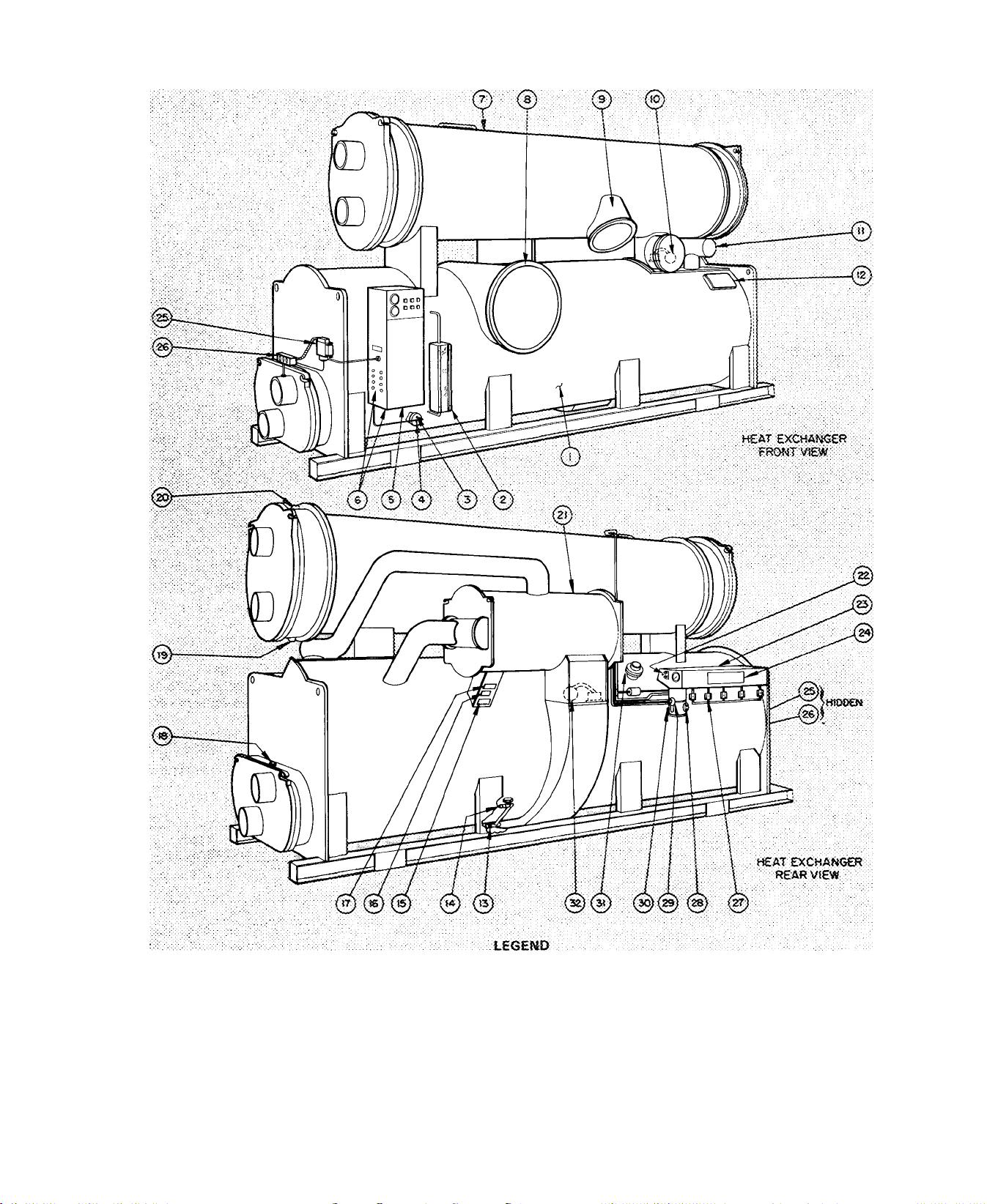
î, Cooier
2. Cooter Befngeranî Lev«} Sight Giass
3. tow Refrigerant Temoerature SiiJb
4. TheroKxneter Weii
5. îv/iachioe Controf Cerner {See P .g. 8 end 9,)
8. Knockouts for P ie!c! Wiring
7. Condenser
S. Cooler Suction Pipe
a. Coocte:Ker Discharge Pipe
■JO. CondenserPloat Veive
■J t. Ecottomizer P'lpe
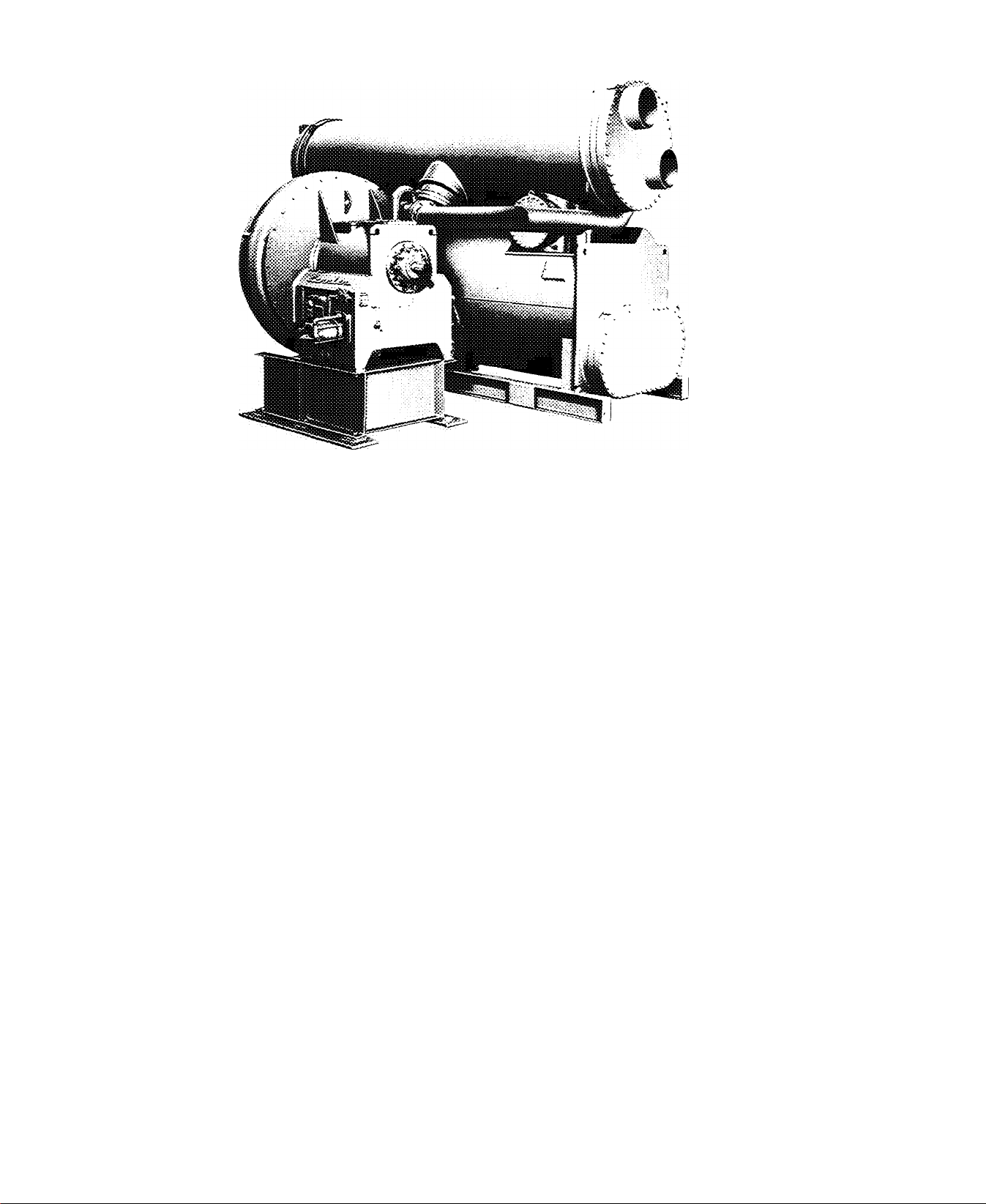
Fig. 1 — 17CB Machine Components (R-11 Unit shown)
12. Cooter-Êconcmizer Ecualiziitg Damper
Access Cover
13. Refrigerant Connection, 1-t/2:MPT
14. Cooter Charging Valve, 3/4 MPT
: 15. ASME Nameplate
16. Machine informative Plate
17. Safety Code Sticker
18. Cooier Waterixix Vent, 3/4 NPT
19. Condenser WaterOox Drain, 3.'4 NPT
20. Condenser Water'oox Vent, 3/4MPT
21. Economizer
22. Purge Operating Switch
23. Tnormal Purge
24. Purge Vaive Operation Plate
25. Chilled Water Low-TemperatureCutout
26. Chilled Water Temperature Probe
27. Purge Operatirig Valves
28. Purge Refrigerant Level Sight Giass
29. Pu:^ Water Level Sight Glass
30. Purge Water Drai n Vaive
31. Rupture Disc Assembl'y
32. Economizer float Vaive
Page 4
I
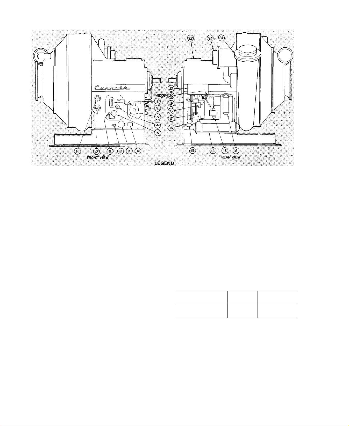
1, OS fieservoif S5g,fit:G:!ass-
2- Oii^C^iargjng EJdow,
Sc&i 01} Return
Sea! Cii Return Pomi>
a
Oil Reservoir Thermosneter
4.
5, Oii Beater Terrninaf Sox
6. Ot! Pump !\tamep!ate
INITIAL PREPARATION
7. 0:i Pomp Terminai Box
a Oii Ciwrging Vatve
■9. Oil Beater Thermostat
10. Oil Pressure Gege
tt. Main Searing Oi!
Thermometer
12. Git Pilte;
Fig. 2 — 17CB Centrifugal Compressor
C.AUTION: Do not start compressor or oil
purap, even for a rotation check, tmiess com
pressor is charged with oil and machine charged
with refri^rant.
Do not apply Yoitage of any kind while
machine is under dehydration vacuum.
Machine Tightness — If machine leak testing and
dehydration was not completed at installation,
check machine tightness (including pumpout sys
tem) as described below. Dehydration must be
repeated if machine has been idle for several weeks
or more after initial dehydration.
Check for Large Leaks — Using one of the methods
described below, pressurize the machine to the
level listed in Table 1. Do not exceed test pressure.
Listen for large leaks as the pressure builds up. If
test pressure holds for one hour, proceed with
Check for Small Leaks.
All 17CB machines may be pressurized with
cylinders of dry air or nitrogen thru the cooler
charging valve. Dry air or nitrogen charging is
preferable to purge or pumpout charging as it
ensures that moisture will not be introduced into the
machine. To pressurize with nitrogen (or dry air):
1. Connect a copper tube from charging valve to
pressure cylinder. Never apply full cylinder
pressure to the pressurizing hne. Follow steps 2
thru 5 in proper sequence.
15. Oii Pressure Oifferenirai
Switch
14. Oi! Cooler
: IS. Gii C>x>}er Solertoid Valve
16. Oil Cooler Plug Cock
T7. Porm "G" Solenoid Valve
15. Vai'te Speed Valve
2.
Open cooler charging valve fully.
3.
Open cylinder regulating valve slowly.
4.
Observe cooler or condenser pressure gage and
IS. form "W' SoiShoid Valve
20. pii PressureReguiating Valve
21. Compressor Controi Wiring
dunctiott 8ox
22. i nspection Cover
23. Economizer Stubout
24. Oischarge Stt:i50ut
close cylinder regulating valve when pressure
reaches test pressure listed in Table 1.
Do not exceed test pressure.!
5. Close cooler charging valve. Remove copper
tube.
Table 1 — Test Pressures
MACHINE SIZE
17CB1300 thru 1600 R-11
17CB1800 thru 2000 R-114
REFRIG
TEST
PRESSURE
8 to 10 psig
30 to 35 psig
Refrigerant 11 machines may be pressurized
with the purge pump. Ensure that electrical supply
to purge pump is 120 volts. Then follow operation
3 on the purge valve chart (item 24, Fig. 1).
Refrigerant 114 machines may be pressurized
with the pumpout unit. This method is detailed in
the section entitled Pumpout Procedures.
Check for Small Leaks
1. Pull a vacuum equal to 5 in. Hg (12.5 psia) by
using purge pump operation 2 (Refrigerant 11
machines), pumpout unit (Refrigerant 114
machines) or by applying a vacuum pump at
the cooler charging valve.
Page 5
r ^
2. Charge approximately 25 lb of the proper
refrigerant thru the cooler charging valve.
3. Pressurize machine to test pressure (Table 1)
using dry air or nitrogen, or purge or pumpout
unit. Do not exceed test pressure.
4. Test all joints, valves, fittings etc. with a halide
or electronic leak detector.
Check Leakage Rate
1. Install a mercury manometer (absolute pressure
type) on a tee at the cooler charging valve.
2. Pull 25 in. of vacuum on the machine.
3. Let machine stand with this vacuum for at least
8 hours.
4. If leakage rate is less than 0.1 in. Hg in 24 hours
(0.033 in. Hg in 8 hours), machine is suffi
ciently tight. Perform Machine Dehydration.
5. If leakage rate exceeds 0.1 in. Hg per 24 hours,
repeat Check for Small Leaks, repair leaks and
repeat this Leakage Rate Check.
6. Remove or valve off manometer before re
peating any pressure test.
Machine Dehydration
Before dehydration, drain shipping oil and flush oil
reservoir. Shipping oil vaporizes under vacuum and
can greatly inhibit dehydration.
6. Wait 2 hours and read manometer again. If
vacuum has not decreased, dehydration is com
plete. If vacuum has decreased, repeat steps 4, 5
and 6.
7. If vacuum fails to hold after several dehydra
tion attempts, check for machine leak by
repeating the refrigerant pressure test.
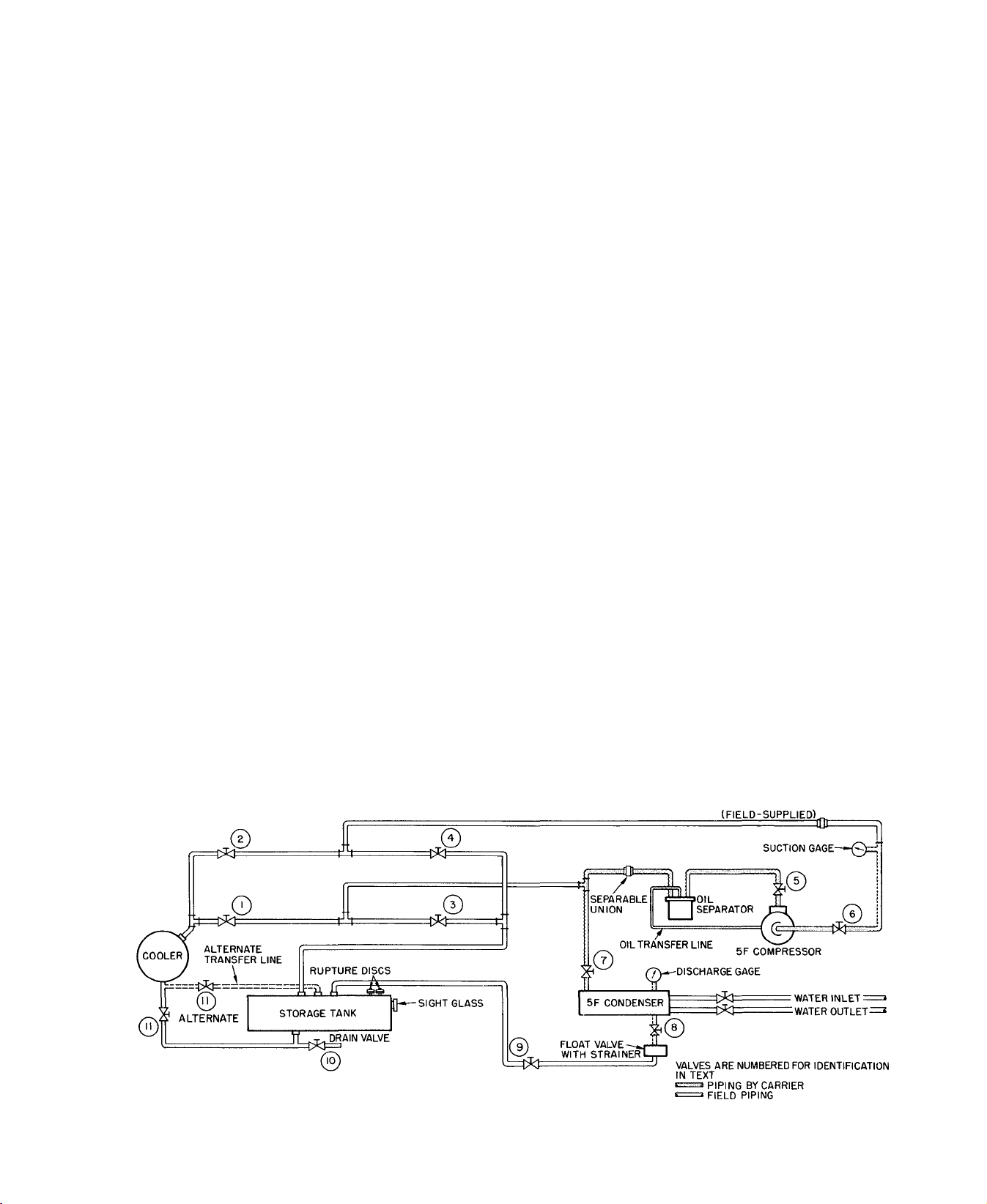
Pumpout Procedures, Refrig 114 Units (See Fig. 3)
MACHINE EVACUATION (No refrigerant in
system)
1. Set purge valves per operation 5 on purge valve
operation plate.
2. Jumper low-pressure cutout on pumpout
compressor.
3. Close valves 1,3,7 and 10.
4. Open valves 2, 4, 5, 6, 8, 9 and 11.
5. Disconnect separable union between pumpout
condenser and oil separator.
6. Run pumpout compressor until desired
machine vacuum is reached.
7. Close valve 5 and reassemble union.
8. Stop compressor.
9. Remove jumper.
CAUTION: Do not attempt to start oil pump
or purge motor even for a rotation check, nor
apply test voltage of any kind while machine is
under dehydration vacuum. Motor insulation
breakdown and serious damage may result,
1. Connect dehydration pump to cooler charging
valve.
2. Ensure that all valves on purge assembly are
closed.
3. Install mercury thermometer (absolute pressure
type) at charging valve tee.
4. Operate pump until manometer reads 29.80 in.
Hg vacuum (0.1 psia). Continue to operate
pump for 2 more hours.
5. Close cooler charging valve; stop pump; record
manometer reading.
PRESSURIZING THE MACHINE (No refrigerant
in system)
1. Set purge valves per operation 4 on purge valve
operation plate.
2.
Close valves 2, 4 and 10.
Open valves 1,3, 5, 6, 7, 8, 9 and 11.
3.
4.
Disconnect separable union in pumpout com
pressor suction line.
5.
Operate pumpout compressor until desired
pressure is reached. Do not exceed test pressure
listed in Table 1.
Shut off pumpout compressor.
6.
7.
Reassemble union.
Return purge valves to Normal-Auto condition
8.
when pressurizing is completed.
SEPARABLE UNION
Fig. 3 — Pumpout System Schematic (R-114 Units)
5
Page 6

I
Recheck Alignment — Angular and parallel align
ment must be within coupling manufacturer’s
specified tolerances before machine is operated.
Refer to Carrier Standard Service Techniques
Manual, Chapter 15, for checking methods.
Leave couplings disassembled until drive is
tested and operated.
Check Grouting — Make sure grouting was applied
during installation. Grouting should be completed
before machine is operated.
Inspect Piping — Refer to piping diagrams provided
in Job Data and inspect piping to cooler, condenser
and oil cooler.
Chilled water should enter the lower nozzle of
the cooler and leave at the upper nozzle. Chilled
water temperature probe should be installed in
leaving chilled water line.
Condenser water should enter the upper con
denser nozzle and leave at the lower.
Ensure that pipes are vented and properly
suspended, with no stress on nozzles or water box
covers.
Measure water pressure drop across cooler and
condenser or across the pumps. Check to see that
water flow agrees with design flow.
Oil cooler water must be clean, with 85 F
maximum temperature and 200 psi maximum inlet
pressure. Refer to tag attached to cooler inlet
connection for pressure drop and velocity limits.
Check that any drive piping is installed per
manufacturer’s instructions.
Field Wiring
Oil may also be added thru charging elbow
(item 2) in seal oil return chamber. The pump
(item 3) automatically transfers oil to the oil
reservoir.
IMPORT.ANT: After char^g oil, energize oil
heater (from its .separate l2D-voit source) to
minimize refrigerant absorption in the oiL Oil
heater indicating light comes on when heater is
energized. The thermostat should be set to
maintain a rhinimum temperature of 140 F at
shutdown. Adjust if required.
On pneumatic machines only, add a small
amount of oil to the vane seal chamber thru 1 /4-in.
pipe plug (Fig. 4) until level reaches bottom of
rack and gear as seen thru Plexiglas cover.
Fig. 4 — Pneumatic Vane Shaft Seal Chamber
WARNING: Do not attempt to check high
voltage supply without proper equipment and
procedure. Serious personal injury can result.
Check with power company for specific
instructions.
Refer to Job Data wiring diagrams and check
field wiring as follows:
1. Wiring, voltage, supply, and rotation of all
electrical equipment; brine pump, condenser
water pump, tower fan.
2. Overload settings on all motor starters.
3. Wiring on all electrical devices on drive; auxil
iary oil pumps, pump starters, etc.
4. Wiring between drive and control center and
compressor junction box.
5. Wiring to pumpout compressor.
6. Oil pump starter voltage against oil pump
nameplate voltage.
Lubrication
COMPRESSOR — Drain and flush out all shipping
oil; then charge oil shipped with machine. It
conforms to Carrier oil specifications for centrif
ugal compressors (listed in the Operating and
Maintenance Instructions). Charge thru oil reser
voir charging valve (item 8, Fig. 2) to middle of
reservoir sight glass. Machine vacuum draws oil
from container.
WARNING: Do not start oU pump^, even for a
rotation check, with madnne in dehydration
vacuum. Check rotation only after compressor
has been charged with oh and cooler has been
charged with refrigerant.
COUPLINGS — Lubricate couplings after they
have been reassembled. Follow manufacturer’s
recommendations for type of lubricant and
lubrication procedure.
NOTE. Do not reassemble couplings until drive has
been run separately.
SPEED INCREASING GEAR - Fill gear casing
with oil recommended by manufacturer. DO NOT
OVERFILL.
DRIVE — Refer to drive manufacturer’s instruc
tions for proper lubrication.
AUXILIARIES — Check all auxiliary pump motor
bearings for proper lubrication. Fill all oilers used
on shaft seals, bearings, etc.
Refrigerant Charge
1. Install a charging valve in the 3/4-in. drum
opening as shown in Fig. 5.
2. Connect a short length of plastic hose (R-11
only) or copper tubing from drum valve to
cooler charging valve.
3. Circulate chilled water during the charging
process.
Page 7

4.
At a vacuiun greater than that indicated in
Table 2, refrigerant will flash into gas and
may cause tube freeze-up. Keep refrigerant
drums upright and admit refrigerant as a gas
until cooler vacuum is less than that listed in
Table 2.
5.
The refrigerant supplied with the machine is in
excess of that required for initial charging.
Charge the amount shown in Table 3, less 200
pounds.
6.
After the machine has been started, it may be
necessary to adjust the charge for optimum
machine performance. For this adjustment, see
Trimming Refrigerant Charge.
Starting procedure of manually started drives may
be initiated after START button is pushed.
Purge — Place the purge operating valves (Fig. 1) in
“Normal-Automatic” position as indicated in
operation 1 on the purge valve operation plate
(item 24, Fig. 1). Operate the purge momentarily
by placing the purge switch in “Manual” position;
then place purge switch in “Auto” position.
Air Supply — Pneumatic Control Only — Check 25
psi air supply to pneumatic temperature controller
and pilot positioner.
Check Safety Control Operation (Electric Motor
Drive)
NOTE: Motor high temperature cutout is field
supplied only per customer’s request.
As the following checks are made, control panel
lights should appear as indicated in the diagrams.
Fig. 5 — Drum Charging Valve
Table 2 — Pressures Corresponding to
32 F Saturation Temperature
REFRIGERANT
n
114
PRESSURE
(in. Hg vacuum)
18.05
3 85
Table 3 — Refrigerant Shipping Charges
MACHINE SIZE REFRIG
17CB1300
17CB1400
17CB1500
17CB1600
17CB1800 114 4400
17CB2000 j 114 4400
11
1 1
11
11
SHIPPING
CHARGE (lb)
2800
3250
3250
3500
Drive — It is good practice to operate the drive
separately before operating compressor. Refer to
drive manufacturer’s instructions for drive pro
tection devices and settings. Check turbine over
speed at this time. Reassemble couplings after
operating drive separately.
If drive is wired for automatic starting, it will
start when compressor START button is pushed.
□ - OFF
1. Open main disconnect (all
power off to starter and
n
ON
STOP
ON
□ n
START OIL
controls). Disconnect main
motor leads in starter.
2. Provide
control circuit
power.
3. Press ON-STOP button
(light goes on). If
n □ □
POWER
SAFETY LOAD
CIRCUIT RECYCLE
n □ n
ON
START OIL
STOP
■ □ □ n
POWER SAFETY LOAD
CIRCUIT RECYCLE
■
ON
STOP
□ n
START
SAFETY CIRCUIT light
does not go on, check
resets on condenser high-
■ ■ ■
POWER
SAFETY LOAD
CIRCUIT RECYCLE
pressure safety, low refrig
erant safety, bearing and motor high tempera
ture circuit breakers and compressor overloads
in starter. Check 3-amp fuse in control center.
If SAFETY CIRCUIT Ught goes on but
LOAD RECYCLE light stays off, check the
chilled water recycle switch (auto-reset).
If both lights go on, manually trip and reset
motor and bearing high temperature circuit
breakers, compressor motor overloads and low
refrigerant temperature cutout to be sure they
cut off the safety Ught. Tripping the chilled
water recycle switch will cut off the LOAD
RECYCLE Ught only.
4. Press ON-STOP button
(Ught goes out). Remove
n □ n
ON
STOP
START
and tag gray striped wire
□ □
from control center ter
■
POWER SAFETY LOAD
CIRCUIT RECYCLE
minal [l^. Refer to ma
chine control schematic in the Operating and
Maintenance Instructions for terminal
location.
PUMP
n
PROGRAM
TIMER
PUMP
PROGRAM
TIMER
OIL
PUMP
n
PROGRAM
TIMER
PUMP
n
PROGRAM
TIMER
OIL
Page 8

5. Start chilled water and
condenser water pumps.
Press ON-STOP button
(Ught goes on).
6. Press OIL PUMP button
for several seconds. Pump
should raise pressure 25 to
27 psi above refrigerant
pressure at machine
shutdown condition.
SAFETY CIRCUIT and
lights should go on.
7. Release OIL PUMP
button. SAFETY CIR
CUIT light and LOAD
RECYCLE light should go
out.
■
ON
STOP
■ □ ■
STOP
START OIL
■
□ □
SAFETY LOAD
POWER
CIRCUIT RECYCLE
ON
START
■ ■ ■
POWER SAFETY LOAD
CIRCUIT RECYCLE
n
□
PUMP
n
PROGRAM
TIMER
PUMP
□
PROGRAM
TIMER
LOAD RECYCLE
■ □ n
ON
STOP
START OIL
■ □ □
POWER SAFETY LOAD
CIRCUIT RECYCLE
PUMP
n
PROGRAM
TIMER
12. Open oil pump main dis
connect. Starter must de
■ □ ■
ON
START OIL
STOP
PUMP
energize. OIL PUMP light
□ □
will remain on for approxi
mately 5 minutes.
OIL PUMP light goes out.
OIL
13. Close oil pump discon
nect. In approximately 10
minutes the program timer
will complete the anti
recycle portion of its cycle
■
POWER SAFETY LOAD
CIRCUIT RECYCLE
■ □ □
ON
STOP
■ □ □ ■
POWER SAFETY LOAD
CIRCUIT RECYCLE
■ □ n
ON
STOP
■
■ ■ n
POWER SAFETY LOAD
CIRCUIT RECYCLE
■
PROGRAM
TIMER
START OIL
STAffT OIL
PUMP
PROGRAM
TIMER
PUMP
PROGRAM
TIMER
and machine is ready to restart. (Total recycle
time is 15 minutes.)
14. Remove all power.
Reconnect motor leads.
Restore power.
8. With OIL PUMP button
depressed, alternately stop
■ □
ON
STOP
START
and restart chilled water
and condenser water
pumps. SAFETY CIR
■ □ □
SAFETY LOAD
POWER
CIRCUIT RECYCLE
CUIT and LOAD RE
CYCLE lights should go out as each pump
stops. (Continuous operation of oil pump is
unnecessary during these checks.)
9. Shut off water pumps. Re
lease OIL PUMP button.
n □ n
ON
STOP
START OIL
Press ON-STOP button
□ □ n
(light out). Replace tagged
■
POWER SAFETY LOAD
CIRCUIT RECYCLE
wire on terminal fl 7j.
10.
Press ON-STOP button
(light goes on).
11. Press machine START
button (motor leads
disconnected).
Oil pump starts within 30
seconds.
Compressor motor start
contacts will close 30
■
STOP
POWER
■ ■
STOP
POWER
STOP PUMP
□
ON
START
■
■ ■
SAFETY LOAD
CIRCUIT RECYCLE
START OIL
ON
■ ■
■
SAFETY LOAD
CIRCUIT RECYCLE
■ ■ ■
START
ON
■
■ ■
POWER
SAFETY LOAD PROGRAM
CIRCUIT RECYCLE TIMER
■ ■
ON
START
STOP
seconds later. Starter will
transfer to its run condi
tion 30 to 60 seconds
■ ■ ■
POWER SAFETY LOAD
CIRCUIT RECYCLE
after starter is energized.
■
OIL
PUMP
n
PROGRAM
TIMER
PUMP
PROGRAM
TIMER
n
OIL
PUMP
n
PROGRAM
TIMER
n
PUMP
■
PROGRAM
TIMER
■
■
PUMP
n
PROGRAM
TIMER
ELECTRONIC CONTROL PNEUMATIC CONTROL
Fig. 6 — Control Center Components
(Electric Motor Drive)
Check Safety Control Operation (Gas Engine or
Turbine Drive)
Refer to machine control schematic in the
Operating and Maintenance Instructions for loca
OIL
tion of electrical terminals listed.
As checks are made, control panel lights
should appear as indicated in the diagrams.
1. Turn off main steam or
gas supply to prevent
OIL
drive from starting. Place
jumpers across oil switch
□ □ □
POWER ON
STOP
(g)
□
OIL
PUMP
oTp
START
□
SAFETY
CIRCUIT
terminals (67} and
and flow switch terminals [69j and [70] inside
the control center.
Page 9

circuit
power.
■ □ □
ON
POWER
STOP
oT, (g)
□
OIL
PUMP
3. Press ON-STOP button
(light on). If SAFETY
CIRCUIT light does not ^
go on, check resets on ^
□
condenser high-pressure
safety, cooler low refrig
erant safety, bearing high temperature circuit
breaker, chilled water low temperature switch
and driver overload in starter. Check 3-amp
fuse in control center.
Manually trip and reset the bearing high
temperature circuit breaker, driver overload,
low refrigerant safety and chilled water switch
to be sure they cut off the safety light.
4. Press ON-STOP button
(light goes out). Remove
jumpers across terminals
(6^ and [0], [6^ and
■ □ □
POWER
ON
STOP
oTp (|1
□
OIL
PUMP
START
□
SAFETY
CIRCUIT
□
START
□
SAFETY
CIRCUIT
9. With OIL PUMP and
ON-STOP switches on,
and water pumps oper
ating, press machine
START button (gas or
steam supply turned ofO
10. Turn off OIL PUMP
switch. Oil pump must
continue operating.
11. Open oil pump main disconnect. Driver circuit
control must de-energize.
Oil pump will remain on
for 3 minutes.
12. OIL PUMP light goes out.
13. Press ON-STOP switch
(light goes off).
(g
■
POWER
oTp (g)
■
POWER ON
oTp (g)
■
POWER ON
gl
■ □
ON
STOP
■
SAFETY
OIL
PUMP
CIRCUIT
■ □
STOP
□
OIL
SAFETY
PUMP
CIRCUIT
□
STOP
□
SAFETY
OIL
PUMP
CIRCUIT
START
□
START
□
□
START
□
5. Start chilled water and
condenser water pumps.
Press ON-STOP button
(light goes on).
■ ■ □
POWER ON
STOP
□
OIL
PUMP
Turn on OIL-PUMP
switch for several seconds.
Pump should raise oil
pressure 25 to 27 psi
(g)
above refrigerant pressure
at machine shutdown con
dition. SAFETY CIRCUIT light should go on.
If oil pump operates but SAFETY CIRCUIT
light is out, check water flow switches.
7. Turn off OIL PUMP
switch. SAFETY CIRCUIT light should go off.
■ ■ □
POWER ON START
□
OIL
PUMP
START
□
SAFETY
CIRCUIT
□
SAFETY
CIRCUIT
□
SAFETY
CIRCUIT
14. Remove all power. Restore gas or steam supply
to drive. Restore power.
CONDENSER
/
COOLER
REFRIG
TEMP
CUT-OUT
TIT“
□ □ □
POWER ON START
STOP
□
OFF^
OIL PUMP CIRCUIT
= K8
Z CAPACITY
SAFETY
o
CONDENSER
PRESSURE
CUT-OUT
ELAPSED
TIME
INDICATOR
CONTROL
MODULE
\
CONDENSER
REFRIG
TEMP
CUT-OUT
OFF
□ □
POWER ON
STOP
OIL PUMP
□
START
□
SAFETY
CIRCUIT
ELAPSED
TIME
INDICATOR
8.
With OIL PUMP switch
on, manually trip and
reset water pump switches.
SAFETY CIRCUIT light
should go off as each
switch is tripped. (Continuous operation of oil
pump is unnecessary during these checks.)
□
START
□
SAFETY
CIRCUIT
RELAY MODULE
I I I I I I i~Tn
ELECTRONIC CONTROL PNEUMATIC CONTROL
RELAY MODULE
I I I I I I I T-|
Fig. 7 — Control Center Components
(Gas Engine or Turbine Drive)
Page 10

START-UP
Preliminary Checks
1. Power on to circuit breakers, water pumps,
cooling tower fans
2. Cooling tower water level
3. Refrigerant level
4. Oil reservoir level
5. Oil reservoir temperature 140 F or warmer
6. Oil cooler plug cock (item 16, Fig. 2) partially
open, and any other valves in oil cooler line
fully open
7. Valves in chilled water and condenser water
circuits open and water circulating properly. Do
not permit water over 100 F to flow thru
cooler.
8. Air supply to pneumatic controls
9. Purge valves and switches in “NormalAutomatic” position. (Refer to chart attached
to purge cover.)
Compressor Rotation and Operation
Electronic Control: Set capacity control switch to
“Hold.”
Pneumatic Control; Turn off supply air to chilled
water thermostat and vane positioner.
Turn on OIL PUMP switch if gas engine or
turbine drive. Press machine ON-STOP and START
buttons (lights go on). As soon as the compressor
shaft begins to turn, note direction of rotation. If
not counterclockwise as viewed from drive end,
stop compressor by pressing ON-STOP button
(light goes out) and correct condition.
If rotation is counterclockwise, let compressor
come up to speed and press ON-STOP button (light
goes out). Listen for any unusual sounds as
compressor coasts to a stop.
The program timer on electric drive units will
allow compressor restart 15 minutes after stop.
Checking Safety Control Settings
While performing these checks, carefully moni
tor chilled water temperature to prevent
freeze-up. Protection by safety controls cannot
be assumed until all settings have been con
firmed as follows.
Shut off gas or steam supply to engine or
turbine. Open main disconnect (all power off to
starter and controls).
Electronic Capacity Control: Set capacity control
switch on “Hold.”
Pneumatic Capacity Control: Ensure that pilot
positioner operates as described in Setting Oper
ating Controls — Pneumatic. If compressor has
electric motor drive, set percent load knob on
demand limit control at 100% and turn calibration
screw fully clockwise.
Install jumpers across low refrigerant and low
chilled water cutouts as follows:
Electric Motor Drive — ^ to (4^ ; (0) to
Gas Engine or Turbine Drive
[TT|.
611 to [621; [71
to
Close disconnects, start compressor and check oil
pressure and temperature. With compressor run
ning, operate the guide vanes with the capacity
control switch or the pneumatic thermostat. Do
not exceed full load condition.
1. Check controls 1 and 2 as indicated in Table 4.
2. Stop machine; open disconnects; remove
jumpers; and check controls 3, 4 and 5 as
indicated.
Table 4 — Setting Safety Controls
SAFETY OR CONTROL DEVICE SAFETY OR CONTROL DEVICE
1. Chilled Water Low-Temperature Cutout and Recycle Switch
(Fig. 1).
-TEMPERATURE ADJUSTMENT
Set this switch to break at approximately 5 F below design
chilled water temperature, or at 36 F whichever is higher
Set the differential at 10 ± 1 F so that when the machine shuts
down automatically at approximately 5 F below the design
chilled water temperature it will restart at approximately 5 F
above the design water temperature
This control must break ahead of the refrigerant lowtemperature cutout switch or the machine will not recycle
automatically
2. Refrigerant Low-Temperature Cutout (Fig. 6 and 7)
ADJUSTMENT
Set refrigerant low-temperature cutout at 33 F or one degree below
design refrigerant temperature, whichever is lower, while checking
temperature at thermowell near control center
10
CUTOUT
Page 11

Table 4 — Setting Safety Controls (cont)
SAFETY OR CONTROL DEVICE
STOP MACHINE, REMOVE JUMPERS AND PERFORM RE
MAINING CHECKS.
3. Condenser High-Pressure Cutout (Fig. 6 and 7).
CUTOUT ADJUSTM^T
COVER
CUTOUT SCALE
RESET
BUTTON
REFRIG
11
114
SETTING
15 psig
45 psig
The condenser high-pressure cutout is factory set to shut the
machine down when condenser pressure reaches setting listed.
Isolate the switch and check setting with a metered supply of air.
4. Oil Heater Thermostat (Fig. 2).
SAFETY OR CONTROL DEVICE
6. Oil Pressure Regulating Valve (Item 20, Fig. 2).
R^FiyC
11
114
SETTING*
15 psid
1 5-20 psid
*Settings given are above
reservoir pressure
SEALING
GASKET
Remove cap and washer and loosen locknut Turn adjusting screw
clockwise to raise oil pressure.
7. Vane Speed Valve (Electronic Machine Only)
Angle valve is located between oil line to main bearing and "F" and
“G" solenoid valves (items 17 and 19, Fig. 2) Set valve at full open
position
8. Chilled Water Flow Switch
Field supplied and installed. Follow switch manufacturer's instruc
tions for adjustment and maintenance
9. Main Bearing Oil Temperature (item 11, Fig. 2)
During machine operation, gauge should read 150 to 165 F. Adjust
water flow thru oil cooler with plug cock (item 16, Fig 2). Do not
exceed 7 gpm or pressure drop of 5 psig. Do not exceed 100 psi
working pressure
SCREW
Set the oil heater thermostat to maintain a minimum oil reservoir
temperature of 140 F at shutdown
5. Low Oil Pressure Cutout (Fig. 2).
RANGE
DIAL ADJUSTMENTTî:
REMOVE METAL
COVER
DIFFERENTIAL
Low oil differential pressure switch is factory set to open at 11 ± 1
psi and close at 15 ± 1 psi differential pressure Operate oil pump
manually Remove cap and gasket from regulating valve and loosen
locknut. Turn adjusting screw counterclockwise to lower oil
pressure to 11 psi differential If safety does not trip, turn range dial
clockwise until cutout occurs
10. Dual Pressurestat for R-114 Pump-Down Compressor
LOW-PRESSURE
SWITCH
COMPRESSOR.
CONNECTIONS
COVER
CUTOUT AND
CUT-IN PRESSURE
. ADJUSTMENT
\jp PRESSURE
l-ADJUSTMENT ONLY
CUTOUT PRESSURE
ADJUSTMENT ONLY
High-pressure switch to open on rise at 45 psig Low-pressure switch
to open on fall at 2 0 in. Hg vacuum.
Set high-pressure switch by operating compressor and throttling
pump-down condenser water while watching pressure gauge.
Set low-pressure switch by operating compressor and gradually
shutting suction valve while watching pressure gauge.
11. Oil Safety Switch for R-114 Pump-Down Compressor
MANUAL
RESET BUTTON
CONNECT IN
SERIES WITH
HIGH PRESSURE
CONN TO
OIL PUMP DISCHARGE
CONTROL CIRCUIT
(SEE WIRING
CONNECT TO
II50R 230V SOURCE
(SEE WIRING DIAGRAM)
DIAGRAM)
Contacts open on drop in oil pressure. Cutout 11-14 psi; cut-in
16-19 psi differential between pump discharge and compressor
suction
Preset switch with an external air source
11
Page 12

Setting Operating Controls — Electronic
MOTOR CURRENT CALIBRATION (Electronic
Capacity Control/Motor Drive)
1. Establish a steady motor current value for this
calibration. Open guide vanes manually
(capacity control to “Inc”) until full load
current is reached. Motor current calibration
(Fig. 8) may need to be turned counter
clockwise to permit vanes to open further. Do
not exceed 105% of nameplate full load
amperes.
If system load is sufficient to maintain full
load current for a period of time, caUbrate at
this condition. With small loads, pull down to
and maintain design leaving chilled water
temperature (capacity control at “Hold”) and
calibrate at this condition.
Fig. 8 — Capacity Control Module
(Electric Motor Drive)
2. Measure motor current at selected condition.
Determine its percentage of full load motor
current.
3. Use this percentage figure to set the electrical
demand adjustment (Fig. 8) per the following
table:
Percent of Full
Load Motor Current
105
85 or above
65 to 84
45 to 64
below 45
Electrical Demand
Adjustment Setting
100 percent
80 percent
60 percent
40 percent
Control cannot be
calibrated
4. Turn the motor current calibration adjustment
fully clockwise. The guide vanes will close part
way.
5. Turn the thermostat adjustment (Fig. 8) to
COOLER (fully counterclockwise).
6. Set capacity control at “Inc” position.
7. Slowly turn the motor current calibration
counterclockwise. Allow the guide vanes to
open until motor current reaches 5% above the
electrical demand setting.
NOTE; There is a time lag of several seconds
due to feedback capacitance in the motor
current circuit. When the motor current cali
bration setting is adjusted, allow for this time
lag.
8. Check the foregoing motor current calibrations
with machine under “Auto” control as
follows:
a. Close vanes manually (capacity control to
DEC).
b. Turn capacity control to AUTO. Vanes
should stop opening at electrical demand
setting.
9. If control was calibrated at less than 100%
load, turn electrical demand adjustment setting
to 100%. Control is now automatically cali
brated for 100% full load current.
10. If control cannot be calibrated with above
procedure, check voltage signal from signal
resistor in starter. At 100% full load current,
voltage between terminals 23 and 24 inside
control center must be 0.5 ± 0.1 volts. If not
in this range, check sizing of resistor in starter.
Both excess motor current and chilled
water temperatures below the thermostat set point
(Fig. 8) will override the capacity control setting.
If the capacity control knob is in the “Inc”
position, the guide vanes will stop opening. With
the knob in any of the other positions, the vanes
will close as needed.
The motor current limiting circuit operates in
two steps.
At 100% full load motor current, the vanes
will stop opening further. If the motor current
should increase to 105% due to some change in
load conditions, the vanes will close until the
motor current is reduced to about 102%.
If the motor current is reduced to 98% or
below, control again operates in response to chilled
water temperature.
The electrical demand adjustment permits the
operator to set the maximum current drawn by the
motor and thus minimize the electrical demand
rate during off-season operation.
CHILLED WATER CALIBRATION (Electronic
Controls)
1. Turn throttle range adjustment (Fig. 8 and 9)
fully clockwise.
A
i.
12
Page 13

\<%A—
max
iol
\<%4-. ^
^Oi ir«&S5“
\o\
Fig. 9 — Capacity Control Module
(Gas Engine or Turbine Drive)
2. Turn chilled water thermostat until design
chilled water temperature is maintained. Mark
thermostat at this position. If capacity control
vanes hunt, turn throttle range adjustment
counterclockwise in small increments until
hunting ceases. Chilled water thermostat may
require resetting.
Setting Operating Controls — Pneumatic
“»<*
\
--
MUtM. fft
i mm «Nft
^ 9mi.y%
i V \ , WOlM«t
. \ sosogn
i -------* m^Si
Preparation:
1. Place jumper between terminals (L^ and
2. Open 25 lb air supply valve.
3. Remove cover from pilot positioner.
Calibration:
Rotate dial on chilled water thermostat to vary
pilot pressure. Observe pressure gage in pilot
supply line near pilot positioner and adjust starting
point nut (2) until piston operator (Fig. 4) begins
to move at 5 psi pilot pressure. Place follower
spring (4) in proper hole in level arm so that piston
operator opens 100% at 15 psi pilot pressure.
Completion:
1. Remove jumper from terminals [L^ and
2. Replace positioner cover.
ELECTRO-PNEUMATIC RELAY (Electric Motor
Drive Only)
LOCKNUTS,
COVER
SENSITIVITY SCREW
SET POINT SCREW
CONTROL AIR
(OUTPUT)
NOTE; if raachiiie has special pne^iipaiic con
trols, follow the instructions supplied in the job
data for their setting and adjustment.
PILOT POSITIONER
MAIN AIR CONNECTION (25 PSIG)
STARTING POINT ADJUSTMENT NUT
LEVER ARM
FOLLOWER SPRING
PILOT AIR CONNECTION
(FROM CONTROL CENTER)
This control is factory calibrated to provide a
linear output signal of 3 psi at 6 volts d-c to 18 psi
at 15 volts d-c. Field recalibration should not be
necessary.
If calibration is required:
1. Establish 15 volt d-c input with 25 psi supply
air.
2. Turn sensitivity screw to obtain 18 psi or higher
output.
3. Adjust setpoint screw, if required, to set output
at 18 ± 1/4 psi.
4. Reduce input to 6 volts. Output should be 3 ±
1/4 psi. If low, turn sensitivity screw carefully
clockwise. If high, turn screw counterclockwise.
5. Re-check output at 15 volts. Repeat steps 3 and
4 if necessary.
1 3
Page 14

DEMAND LIMIT CONTROL
CALIBRATION
ADJUSTMENT
% LOAD DIAL
COVER
BANDWIDTH
DIAL
1. Set percent load dial at 100%.
2. Set Band Width dial at 3.
3. Turn Calibration Adjustment screw fully
clockwise.
4. Run machine at 100% LLA by adjusting dial on
chilled water thermostat.
5. Turn Cahbration Adjustment screw counter
clockwise until guide vanes just begin to close.
6. If hunting occurs, increase band width and
repeat steps 4 and 5.
7. If control cannot be calibrated with above
procedure, check voltage signal from resistor in
starter. At 100% full load, voltage between
terminals 23 and 24 inside control center must
be 3.0 ± 0.1 volts. If not in this range, check
sizing of resistor in starter.
CHILLED WATER THERMOSTAT (PNEUMATIC)
Preparation;
1. Ensure 25 psi supply air to thermostat.
2. Loosen Allen setscrew in sensitivity slider and
move slider halfway between midpoint and DA.
Re tighten screw.
Cahbration:
1. Turn thermostat dial until control air registers
15 psi.
2. Operate machine to reach design chilled water
temperature at design load. Maintain 15 psi
control air during pulldown by adjusting ther
mostat dial as required.
3. On reaching design chilled water temperature,
turn dial until control air pressure holds
machine at design conditions.
4. Hold setpoint adjusting screw stationary within
the dial post and set the thermostat dial at
design chilled water temperature.
^ Completion:
If vane hunting occurs, move sensitivity slider
away from DA. Sensitivity decreases as slider is
moved from 5 psi/F to the lower limit of 0.1 psi/F.
Trimming Refrigerant Charge — After machine is
placed in operation, it may be necessary to adjust
the refrigerant charge to obtain optimum machine
performance.
When machine full load is available, slowly add
a sufficient amount of the remaining 200 lb of
refrigerant until the difference between leaving
chilled water temperature and cooler temperatures
reaches design conditions or becomes a minimum.
Shut down machine. Mark maximum refrigerant
level. Maintain refrigerant at this level.
ITEM DESCRIPTION
1 SET POINT ADJUSTING SCREW
2 THERMOSTAT DIAL
3 SENSITIVITY SLIDER
4 SUPPLY AIR PRESSURE GAGE
5 SUPPLY AIR CONNECTIONS
6 CONTROL AIR PRESSURE GAGE
7 CONTROL AIR CONNECTIONS
8 DIAL RETAINING SCREW (2)
Hot Alignment Check — When all machine com
ponents have reached operating temperature (after
running near full load for approximately two
hours), a hot alignment check must be made.
1. Shut down machine.
2. Quickly disassemble couplings between com
pressor and drive (and gear, if used).
3. Check angular and parallel alignment in plan and
elevation. Indicators may be mounted as in Fig.
10. Refer to coupling manufacturer’s instruc
tions and to Carrier Standard Service Tech
niques, Chapter 15, for applicable procedures.
4. After making adjustments, reassemble the
couplings and run the machine until it reaches
operating temperature.
5. Repeat steps 1 thru 3 until angular and parallel
alignment is within coupling manufacturer’s
specified tolerances.
14
Page 15

1
£
\
Fig. 10 — Checking Alignment with Dial Indicator
TO CHHCK ANGOi-AR AtJGNMSXT
A second method of checking hot alignment
can be used if there is room on the shafts between
equipment and coupling to clamp a sturdy bracket.
Clamping tool, Part No. TS-170, is available for
this purpose thru Carrier Service Parts Department.
Check with your local Carrier Office. Dial indicator
must be obtained separately. Clamps must have
space to rotate with the shaft. This method is
quicker because couplings do not have to be
disassembled. Mount brackets and dial indicators as
in Fig. 11. Since both shafts are rotating together,
concentricity and condition of the faces are not
problems. The diameter used in the angular
alignment formula is the circle thru which dial
indicator rotates. This method is more accurate
since the diameter is larger.
Doweling — After hot alignment is completed, the
compressor, gear and drive must be doweled to
their soleplates. This permits repositioning of
components if they have to be moved. Compressor
has four 3/4-in. holes for doweling.
1. Drill thru these holes into the soleplates Ream
holes with a tapered reamer with straight flutes.
2. Coat dowels with white lead or other lubricant
to prevent rusting.
3. Tap dowels lightly into position with a small
hammer. A ringing sound indicates the proper
seating.
TO CHECK PARALLSL AUGNMSiT
Fig. 11 — Alignment Check — Assembled Coupling
Repeat these steps with gear and drive, keeping
dowels as vertical as possible. Dowel thru the four
3/4-in. holes on suction end of compressor base,
the two feet on high speed end of gear, and the
drive feet adjacent to gear. Refer to drive man
ufacturer’s instructions for additional details on
doweling this equipment.
Page 16

INSTRUCTING THE CUSTOMER OPERATOR
Be sure the operator carefully reads and under
stands the 17CB Operating and Maintenance In
structions and any instructions on drive operation
and maintenance.
Point out the following machine components,
explain their function and that of the system in
which they are used.
1. Compressor-Motor Assembly
a. Guide Vanes, Vane Motor and Linkage
2. Cooler-Condenser-Economizer
a. Float Chamber, Sight Glasses
b. Thermowells
c. Rupture Disc
d. Refrigerant Charging Valve
3. Purge System
a. Importance of Proper Operation
b. Valves and System Operation
c. Sight Glasses, Gage
4. Lubrication System
a. Oil Pump, Cooler, Filter
b. Solenoid Valve, Plug Cock
c. Heater, Thermostat, Temperature Gage
d. Pressure Regulating Valve
e. Oil Level, Temperature
5. Control System
a. Manual Switches (ON-STOP, START,
OIL-PUMP)
b. Gages and Lights
c. Safety Controls
d. Operating Controls
e. Auxiliary and Special Controls
6. Auxiliary Equipment
a. Starter(s)
b. Pumps
c. Cooling Tower
d. Pumpout System (if supplied)
Describe Refrigeration Cycle
Review Maintenance
1. Scheduled
2. Extended Shutdown
3. Importance of Log Sheet
4. Importance of Water Treatment
Check Operator Knowledge
1. Start-Stop Procedure
2. Safety and Operating Controls
Discuss Carrier Service
1. Availability
2. Method of Ordering Parts
Review Operating and Maintenance Instructions
For replacement items use Carrier Specified Parts.
Manufacturer reserves the right to discontinue, or change at any time, specifications or designs without notice and without incurring obligations.
Book 2
Tab
5d
Form17CB-2SS Supersedes 17CB-1SS Printed in U.S.A.
3-79
PC 211
Catalog No 531—740
 Loading...