

Page 1
Installation Instructions
SAFETY CONSIDERATIONS
Centrifugal liquid chillers are designed to provide safe and
reliable service when operated within design specifications.
Whenoperatingthisequipment, usegood judgmentand safety
precautions to avoid damage to equipment and property or
injury to personnel.
Be sure you understand and follow the procedures andsafety
precautions contained in the machine instructions, as well
as those listed in this guide.
DO NOT VENT refrigerant relief devices within a building. Outlet from
rupture disc or relief valve must be vented outdoors in accordance with
the latest edition of ASHRAE (American Society of Heating, Refrigeration and Air Conditioning Engineers) 15. The accumulation of refrigerant in an enclosed space can displace oxygen and cause
asphyxiation.
PROVIDE adequate ventilation in accordance with ASHRAE 15, especially for enclosed and low overhead spaces. Inhalation of high
concentrations of vapor is harmful and may cause heart irregularities,
unconsciousness, or death. Intentional misuse can be fatal. Vapor is
heavier than air and reduces the amount of oxygen available for breathing. Product causes eye and skin irritation. Decomposition products are
hazardous.
DO NOT USE OXYGEN to purge lines or to pressurize a machine for
any purpose. Oxygen gas reacts violently with oil, grease, and other
common substances.
DO NOT USE air to leak test. Use only refrigerant or dry nitrogen.
NEVER EXCEED specified test pressures. VERIFY the allowable test
pressure by checking the instruction literature and the design pressures
on the equipment nameplate.
DO NOT VALVE OFF any safety device.
BE SURE that all pressure relief devices are properly installed and func-
tioning before operating any machine.
DO NOT WELD OR FLAMECUT any refrigerant line or vessel until
all refrigerant (liquid and vapor) has been removed from chiller. Traces
of vapor should be displaced with dry air or nitrogen and the work area
should be well ventilated. Refrigerant in contact with an open flame
produces toxic gases.
DO NOT USE eyebolts or eyebolt holes to rig machine sections or the
entire assembly.
DO NOT work on high-voltage equipment unless you are a qualified
electrician.
DO NOT WORK ON electrical components, including control panels,
switches, starters, or oil heater until you are sure ALL POWER IS OFF
and no residual voltage can leak from capacitors or solid-state
components.
LOCK OPEN AND TAGelectrical circuits during servicing. IF WORK
IS INTERRUPTED, confirm that all circuits are deenergized before
resuming work.
AVOID SPILLING liquid refrigerant on skin or getting it into the eyes.
USE SAFETY GOGGLES. Wash any spills from the skin with soap
and water. If liquid refrigerant enters the eyes, IMMEDIATELYFLUSH
EYES with water and consult a physician.
NEVER APPLY an open flame or live steam to a refrigerant cylinder.
Dangerous over pressure can result. When it is necessary to heat refrigerant, use only warm (110 F [43 C]) water.
17/19EX
50/60 Hz
Centrifugal Liquid Chillers
with HFC-134a
DO NOT REUSE disposable (nonreturnable) cylinders or attempt to
refill them. It is DANGEROUS AND ILLEGAL. When cylinder is emptied, evacuate remaining gas pressure, loosen the collar, and unscrew
and discard the valve stem. DO NOT INCINERATE.
CHECK THE REFRIGERANT TYPE before adding refrigerant to the
machine. The introduction of the wrong refrigerant can cause
machine damage or malfunction.
Operation of this equipment with refrigerants other than those cited
herein should comply with ASHRAE-15 (latest edition). Contact
Carrier for further information on use of this machine with other
refrigerants.
DO NOT ATTEMPT TO REMOVE fittings, covers, etc., while
machine is under pressure or while machine is running. Be sure pressure is at 0 psig (0 kPa) before breaking any refrigerant connection.
CAREFULLY INSPECT all relief valves, rupture discs, and other relief devices AT LEAST ONCE A YEAR. If machine operates in a corrosive atmosphere, inspect the devices at more frequent intervals.
DO NOT ATTEMPTTOREP AIROR RECONDITION any relief valve
when corrosion or build-up of foreign material (rust, dirt, scale, etc.) is
found within the valve body or mechanism. Replace the valve.
DO NOT install relief devices in series or backwards.
USE CARE when working near or in line with a compressed spring.
Sudden release of the spring can cause it and objects in its path to act
as projectiles.
DO NOT STEP on refrigerant lines. Broken lines can whip about, and
release refrigerant, causing personal injury.
DO NOT climb over a machine. Use platform, catwalk, or staging. Follow safe practices when using ladders.
USE MECHANICAL EQUIPMENT (crane, hoist, etc.) to lift or move
inspection covers or other heavy components. Even if components are
light, use mechanical equipment when there is a risk of slipping or
losing your balance.
BE AWARE that certain automatic start arrangements CAN ENGAGE
THE STAR TER,TOWERFANOR PUMPS. Open the disconnectahead
of the starter, tower fan, and pumps. Shut off the machine or pump
before servicing equipment.
USE only repaired or replacement parts that meet the code requirements of the original equipment.
DO NOT VENT OR DRAIN waterboxes containing industrial brines,
liquid, gases, or semisolids without the permission of your process control group.
DO NOT LOOSEN waterbox cover bolts until the waterbox has been
completely drained.
DOUBLE-CHECK that coupling nut wrenches, dial indicators, or other
items have been removed before rotating any shafts.
DO NOT LOOSEN a packing gland nut before checking that the nut
has a positive thread engagement.
PERIODICALLY INSPECT all valves, fittings, and piping for corrosion, rust, leaks, or damage.
PROVIDE A DRAIN connection in the vent line near each pressure
relief device to prevent a build-up of condensate or rain water.
Manufacturer reserves the right to discontinue, or change at any time, specifications or designs without notice and without incurring obligations.
Book 2 2
Tab 5a 5d
PC 211 Catalog No. 531-749 Printed in U.S.A. Form 17/19EX-2SI Pg 1 3-96 Replaces: 17/19EX-1SI
Page 2
CONTENTS
Page
SAFETY CONSIDERATIONS ...................1
INTRODUCTION ..............................2
General ......................................2
Job Data ....................................2
Equipment Required .........................2
INSTALLATION .............................2-30
Receiving the Machine .......................2
• INSPECT SHIPMENT
• IDENTIFY MACHINE
• PROVIDE MACHINE PROTECTION
Rigging the Machine .........................2
• RIG MACHINE ASSEMBLY
• RIG MACHINE COMPONENTS
• COMPONENT DISASSEMBLY
Install Machine Supports ....................14
• INSTALL STANDARD ISOLATION
• INSTALL OPTIONAL ISOLATION
• INSTALL SPRING ISOLATION
Connect Piping .............................17
• INSTALL WATER PIPING TO HEAT
EXCHANGERS
• INSTALL WATER TO OIL COOLER ON FA
COMPRESSORS
• INSTALL VENT PIPING TO RELIEF DEVICES
Make Electrical Connections .................20
• CONNECT CONTROL INPUTS
• CONNECT CONTROL OUTPUTS
• CARRIER COMFORT NETWORK INTERFACE
Install Field Insulation .......................28
• FACTORY INSULATION (OPTIONAL)
INSTALLATION START-UP REQUEST
CHECKLIST .............................CL-1
INSTALLATION
Receiving the Machine
INSPECT SHIPMENT
Do not open any valves or loosen any connections. The
standard 17/19EX machine may be shipped with a nitrogen holding charge or with the refrigerant charge isolated within the utility vessel.
1. Inspect for shipping damage while machine is still on shipping conveyance. If machine appears to be damaged or
has been torn loose from its anchorage, have it examined
by transportation inspectors before removal. Forward claim
papers directly to transportation company. Manufacturer
is not responsible for any damage incurred in transit.
2. Check all items against shipping list. Immediately notify
the nearest Carrier representative if any item is missing.
3. Toprevent loss or damage, leave all parts in original packages until beginning installation. All openings are closed
with covers or plugs to prevent dirt and debris from entering the machine’s components during shipping. A full
operating oil charge is placed in the oil sump of the compressor before shipment.
IDENTIFY MACHINE — The machine model number,
serial number, and heat exchanger sizes are stamped on
machine identification nameplate (Fig. 1). Check this information against shipping papers and job data.
PROVIDE MACHINE PROTECTION — Protect machine
and starter from construction dirt and moisture. Keep protective shipping covers in place until machine is ready for
installation.
If machine is exposed to freezing temperatures after water
circuits have been installed, open waterbox drains and remove all water from cooler and condenser.Leave drains open
until system is filled.
INTRODUCTION
General —
wired, and leak tested. Installation consists primarily of establishing water and electrical services to the machine. The
rigging, installation, field wiring, field piping and insulation
are the responsibility of the contractor and/or customer. See
Fig. 1 for model number information.
The 17/19EX machine is factory assembled,
Job Data
Necessary information consists of:
• job contract or specifications
• machine location prints
• rigging information
• piping prints and details
• field wiring drawings
• starter manufacturer’s installation details
• Carrier certified drawings
Equipment Required
• mechanic’s tools (refrigeration)
• volt-ohmmeter and clamp-on ammeter
• leak detector (halide or electronic)
• absolute pressure manometer or wet-bulb vacuum
indicator
• portable vacuum pumps
Rigging the Machine — The 17/19EX machine can
be rigged as an entire assembly. It also has flanged connections that allow the compressor, utility vessel, cooler, and
condenser sections to be separated for ease of installation.
Figures 2 and 3 show 17/19EX components.
RIG MACHINEASSEMBLY— See rigging instructions on
label attached to machine. Also refer to the rigging information found in Fig. 4-9 and Tables 1-12. Lift machine only
fromthe 4 points indicated in rigging guide.Each lifting cable
or chain must be capable of supporting the entire weight of
the machine.
Lifting machine from points other than those specified
may result in serious damage to the unit and personal
injury. Rigging equipment and procedures must be adequate for machine weight. See Table 1 for machine
weights.
NOTE: These weights are broken down into component sections for use when installing the unit in
sections. For the complete machine weight, add all component sections and refrigerant charge together. Total
machine weight is also stenciled on the cooler and condenser sections.
2
Page 3
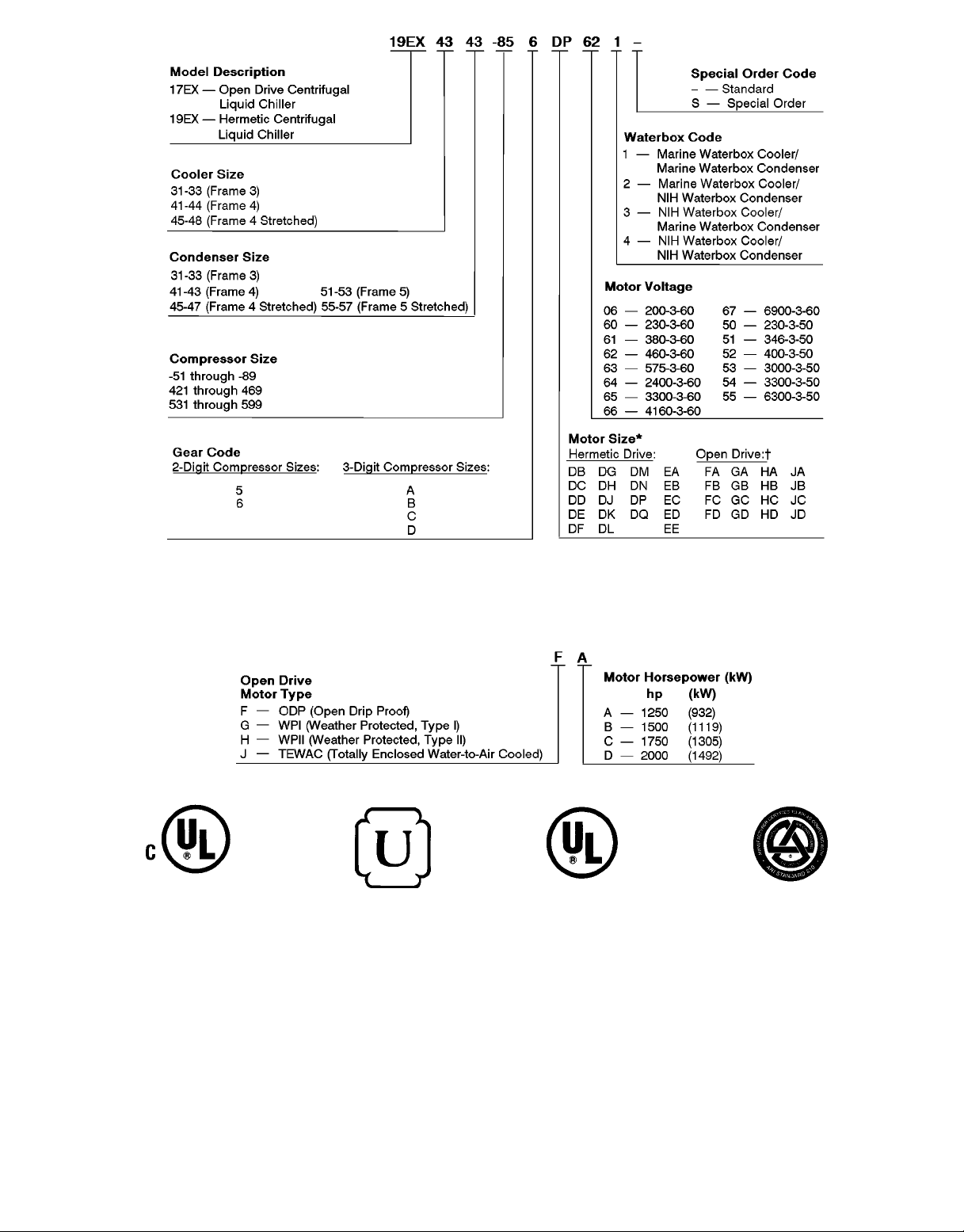
NIH — Nozzle-In-Head
*Motors beginning with ‘‘E’’ and open drive motors (FA-JD) cannot be used with size 51-89 or 421-469 compressors.
†Open-drive motor codes:
ASME
‘U’ STAMP
UNDERWRITERS’
LABORATORIES
Fig. 1 — Model Number Identification
3
ARI (Air Conditioning
and Refrigeration
Institute)
PERFORMANCE
CERTIFIED
(60 Hz Only)
Page 4
RIG MACHINE COMPONENTS — Refer to instructions
on page 5, Fig. 6-8, and Carrier certified drawings for machine component disassembly.
IMPORTANT: Onlya qualified servicetechnician should
disassemble and reassemble the machine. After reassembly,the machine must be dehydrated and leak tested.
When rigging components separately, the open drive
(17EX) motor must be removed to avoid overturning.
Do not attempt to disconnect flanges while the machine
is under pressure. Failure to relieve pressure can result
in personal injury or damage to the unit.
Before rigging the compressor, disconnect the wires
leading from the power panel to the control center at the
power panel.
NOTE: Wiring for sensors must be disconnected. Label each
wire before removal (see Carrier certified drawings).
Detach all transducer and sensor wires at the sensor, then
clip all wire ties necessary to remove the wires from the heat
exchangers.
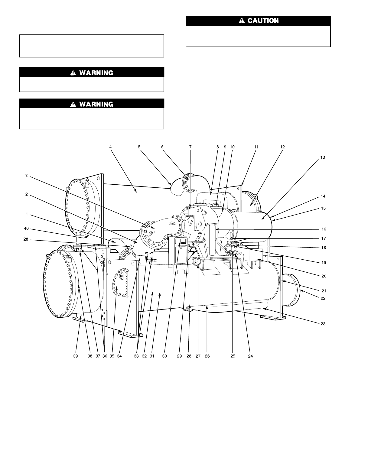
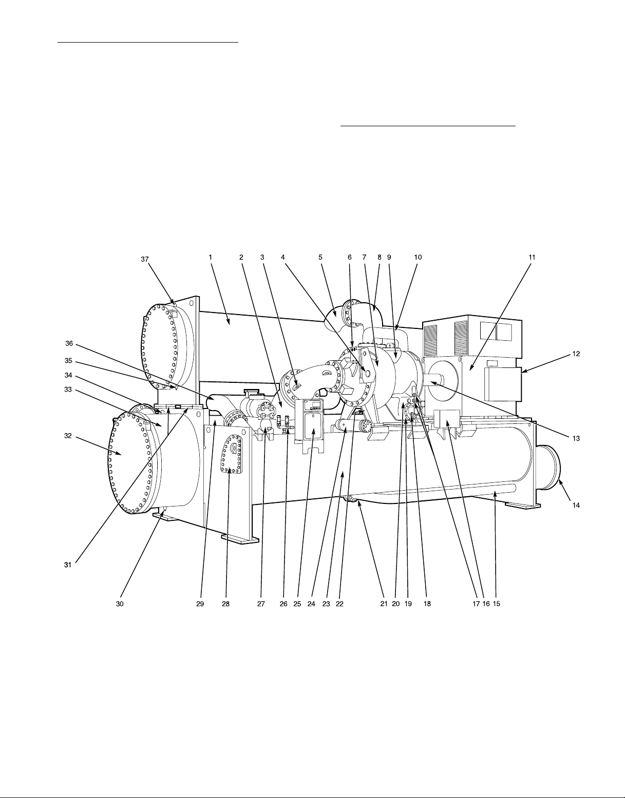
1—Refrigerant Liquid Line to Economizer/
Storage Vessel
2—Cooler Suction Pipe
3—Compressor Suction Elbow
4—Condenser
5—Condenser Discharge Pipe
6—Compressor Discharge Elbow
7—Guide Vane Actuator
8—Economizer Gas Line to Compressor
9—Gear Inspection Cover
10 — 2-Stage Hermetic Compressor
11 — Condenser Waterbox Vent (Not Shown)
12 — Condenser Marine Waterbox
13 — Hermetic Compressor Motor
14 — Compressor Motor Terminal Box
(Not Shown)
19EX
LEGEND
15 — Motor Sight Glass (Not Shown)
16 — Oil Filter
17 — Oil Level Sight Glasses (2)
18 — Cooler Relief Valves (Not Shown)
19 — Oil Heater (Not Shown)
20 — Auxiliary Power Panel
(Field Wiring Terminals)
21 — Pumpdown Unit (Not Shown)
22 — Low-Side Float Box Cover
23 — Refrigerant Liquid Line to Cooler
24 — Oil Drain and Charging Valve
25 — Oil Pump
26 — Refrigerant Charging/Service
Valve 10 (Not Shown)
Fig.2—Typical 19EX Installation
4
27 — Oil Cooler
28 — Isolation Valves (Not Shown)
29 — Refrigerant Filter Drier
30 — Local Interface Display Control Panel
31 — Economizer/Storage Vessel
32 — Rigging Guide (Not Shown)
33 — Economizer/Storage Vessel
Relief Valves
34 — Cooler
35 — High-Side Float Box Cover
36 — Take-Apart Connections
37 — Cooler Waterbox Vent
38 — Cooler Marine Waterbox
39 — Cooler Waterbox Drain
40 — Condenser Waterbox Drain
Page 5
COMPONENT DISASSEMBLY
To Separate Compressor from the Machine
1. Make sure to check that the machine is at atmospheric
pressure before disassembly.
2. Since the center of gravity is high on 17EX machines,
the motor MUST be removed before rigging the
machine.
3. Suction elbow should be rigged separately (Fig. 6,
Item 2). Place slings around the elbow and attach to the
hoist. Remove bolting at flanges, (Fig. 6, Items 1 and 3).
Detach the elbow.
4. Unbolt discharge flange to the condenser at flange
(Fig. 8, Item 3). Cut copper lines (Fig. 6, Items 7, 8,
and 9).
5. Disconnect and detach the economizer vent line
(Fig. 8, Item 4). Unbolt the line at flange (Fig. 8,
Item 2).
6. On 19EX machines, disconnect the motor cooling drain
line at flange (Fig. 8, Item 5).
7. Disconnect wiring to the control center and power panel.
8. Connect rigging to the compressor.
9. Unbolt compressor from the utility vessel (Fig. 7,
Items 2, 4, and 5).
10. Hoist the compressor off of the unit.
11. If the compressor is to be transported or set down,
the base should be bolted to sections of 4 in.x6in.
lumber.
To Separate Condenser from the Machine
1. Unbolt flange (Fig. 6, Item 3).
2. Unbolt flange (Fig. 6, Item 4).
3. Cut copper pipe (Fig. 6, Item 7).
4. Unbolt hot flange (Fig. 7, Item 1).
5. Connect rigging to all corners of the condenser.
6. Unbolt condenser feet (Fig. 8, Items 1 and 6).
1—Condenser
2—Cooler Suction Pipe
3—Compressor Suction Elbow
4—Guide Vane Actuator
5—Condenser Discharge Pipe
6—Oil Filter (Hidden)
7—Two-Stage Compressor
8—Compressor Discharge Elbow
9—Gear Inspection Cover
10 — Economizer Gas Line to Compressor
11 — Open Drive Compressor Motor
12 — Compressor Motor Terminal Box
13 — Coupling Guard
14 — Low-Side Float Box Cover
LEGEND
15 — Refrigerant Liquid Line to Cooler
16 — Power Panel (Field Wiring Terminals)
17 — Oil Level Sight Glasses
18 — Oil Drain and Charging Valve
19 — Oil Heater (Hidden)
20 — Oil Pump
21 — Refrigerant Charging/Service Valve
10 (Not Shown)
22 — Cooler Relief Valves (Not Shown)
23 — Economizer/Storage Vessel
24 — Oil Cooler
25 — Control Center
26 — Economizer/Storage Vessel
Relief Valves
Fig.3—Typical 17EX Installation
5
27 — Pumpout Unit
28 — High Side Float Box Cover
29 — Cooler
30 — Cooler Waterbox Drain
31 — Take-Apart Connections (Typical)
32 — Cooler Marine Waterbox Cover
33 — Cooler Waterbox
34 — Cooler Waterbox Vent
35 — Condenser Waterbox Drain
36 — Refrigerant Liquid Line to
Economizer/Storage Vessel
37 — Condenser Waterbox Vent
Page 6
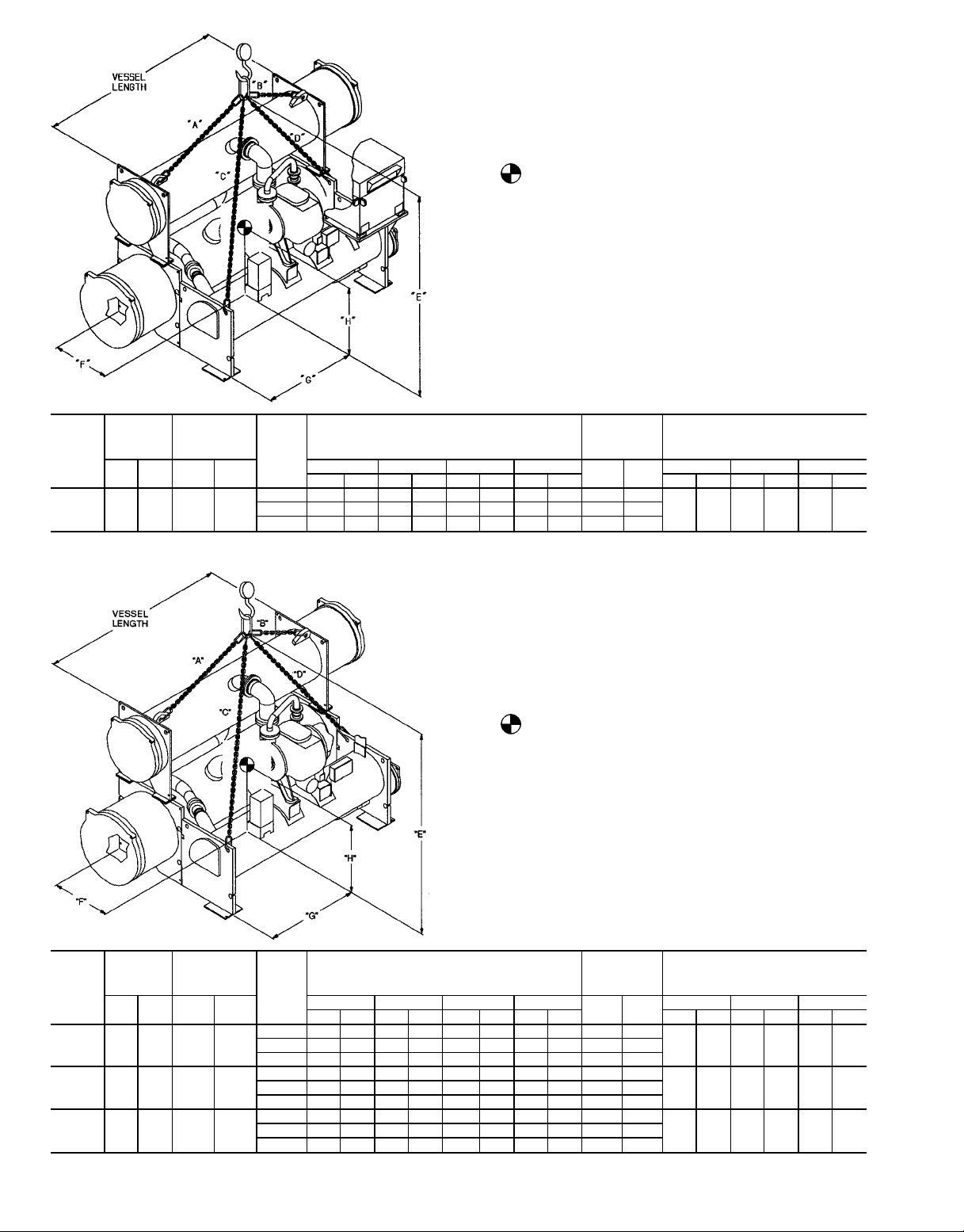
NOTES:
1. Each chain must be capable of supporting the maximum weight of the
machine.
2. = the approximate center of gravity.
3. Maximum possible weight is 88,500 lb (40 166 kg) which includes a maximum of 6,000 lb (2 721 kg) of HFC-134a refrigerant in the storage tank.
17EX FRONT VIEW
VESSEL
COOLER
SIZE
45-48 17-0 5182 88,550 40 166
LENGTH
ft-in. mm lb kg
MAXIMUM
WEIGHT
LIFTING
LIFTING
ANGLE
30° 10- 3 3124 9-0 2743 16-1 4902 13-6 4115 16-11 5156
60° 17-10 5436 17-1 5207 24-9 7544 22-8 6909 27- 3 8306
‘‘A’’ ‘‘B’’ ‘‘C’’ ‘‘D’’
ft-in. mm ft-in. mm ft-in. mm ft-in. mm ft-in. mm ft-in. mm ft-in. mm
CHAIN LENGTH
HEIGHT
FROM FLOOR
‘‘E’’
ft-in. mm
Fig. 4 — 17EX Machine Rigging Guide
NOTES:
1. Each chain must be capable of supporting the maximum weight of the
machine.
2. = the approximate center of gravity.
3. Maximum possible weight is 78,700 lb (35,698 kg) which includes a maximum of 6,000 lb (2,268 kg) of HFC-134a in the storage tank.
19EX FRONT VIEW
CENTER OF GRAVITY
APPROXIMATE LOCATION
‘‘F’’ ‘‘G’’ ‘‘H’’
4-1 1245 9-1 2769 4-9 144845° 12- 7 3835 11-7 3531 19-1 5817 16-9 5105 20- 8 6299
VESSEL
COOLER
SIZE
31-33 12-3 3734 55,000 24 948
41-44 12-3 3734 70,000 31 752
45-48 17-0 5182 78,700 35 698
LENGTH
ft-in. mm lb kg
MAXIMUM
WEIGHT
LIFTING
LIFTING
ANGLE
30° 7-2 1880 7-2 1880 11-11 3632 11-1 3378 13-7 4140
60° 12-5 3785 12-5 3785 18- 0 5486 17-6 5334 20-9 6325
30° 6-7 2007 6-9 2057 13- 0 3962 12-2 3708 15-1 4597
60° 11-4 3454 11-6 3505 18- 7 5664 18-0 5486 21-7 6579
30° 9-1 2769 9-6 2896 15- 1 4597 14-7 4445 16-4 4978
60° 15-9 4800 16-0 4877 22-10 6960 22-6 6858 25-5 7747
‘‘A’’ ‘‘B’’ ‘‘C’’ ‘‘D’’
ft-in. mm ft-in. mm ft-in. mm ft-in. mm ft-in. mm ft-in. mm ft-in. mm
CHAIN LENGTH
HEIGHT
FROM FLOOR
‘‘E’’
ft-in. mm
Fig. 5 — 19EX Machine Rigging Guide
6
CENTER OF GRAVITY
APPROXIMATE LOCATION
‘‘F’’ ‘‘G’’ ‘‘H’’
3-10 1168 6-1 1854 4-6 137245° 8-9 2667 8-9 2667 14- 0 4267 13-4 4064 16-2 4928
4- 0 1219 6-0 1829 4-8 142245° 8-0 2438 8-3 2515 14-11 4547 14-3 4343 17-5 5309
3-10 1168 8-3 2515 4-8 142245° 11-1 3378 11-6 3505 17- 9 5410 17-4 5283 19-8 5994
Page 7
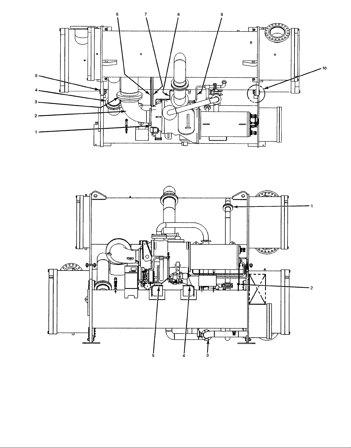
NOTE: Item numbers are referenced in Rigging the Machine, Component Disassembly section.
Fig.6—Typical Top View (19EX Shown)
NOTE: Item numbers are referenced in Rigging the Machine, Component Disassembly section.
Fig.7—Typical Side View (19EX Shown)
7
Page 8
NOTE: Item numbers are referenced in Rigging the Machine, Component Disassembly section.
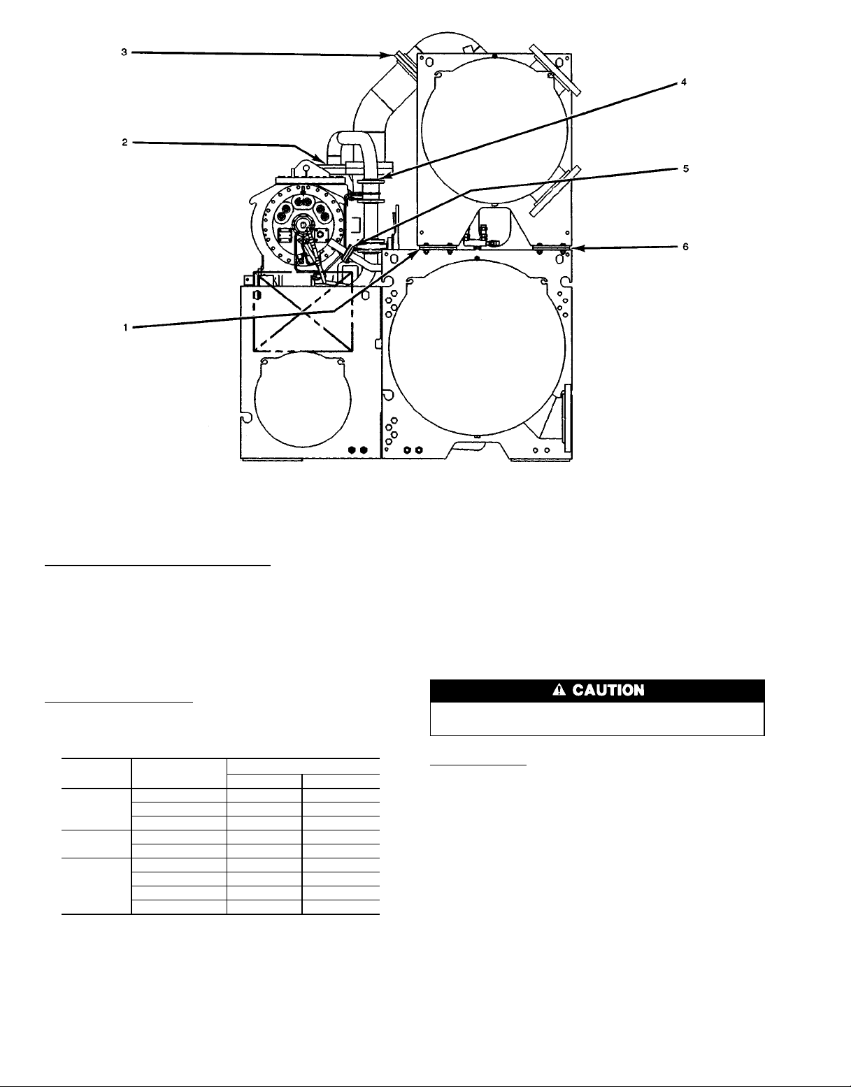
Fig.8—Typical Motor End View (19EX Shown)
To Separate Cooler From Utility Vessel
1. Remove condenser (see previous section).
2. Cut copper lines (Fig. 6, Items 6 and 8).
3. Unbolt liquid refrigerant line at flange (Fig. 7, Item 3).
4. Connect rigging to all four corners of the cooler before
lifting the unit.
5. Unbolt connections to the utility vessel (Fig. 6, Items 5
and 10).
To Assemble the Machine
1. Follow disassembly instructions (in reverse order) and bolt
all flanges back together using a gasket sealant. The following torque requirements are specified:
FIG. ITEM NO.
6
7
8
N-m — Newton Meters
*This torque is used to rig the entire machine. Once the machine
is in place, if no further rigging is anticipated, the bolt torque can
be reduced to 280 ft-lb (380 N-m).
3 580 786
1 or 4 170 230
5 and 10 840* 1139*
1 380 515
4 and 5 250 340
1 and 6 280 380
2 170 230
3 380 515
57196
TORQUE
ft-lb N-m
2. All gasketed or O-ring joints which have been disassembled must be assembled using new gaskets and O-rings.
These new gaskets and O-rings (along with gasket sealant, O-ring lubricant, and copper line couplings) are available through your Carrier representative.
3. Braze all copper lines back together using a suitable brazing material for copper. Carrier recommends an AWS
(American Welding Society) Classification BCuP-2.
Do not tilt the compressor; oil is contained in the oil
sump.
Additional Notes
1. Use silicon grease on new O-rings when refitting.
2. Use gasket sealant on new gaskets when refitting.
3. Cooler, utility, and condenser vessels may be rigged vertically, as separate components. Rigging should be fixed
to all four corners of the tube sheet.
4. New gaskets, grease for O-rings, and gasket sealant for a
complete take-apart operation are available in a kit. Contact your Carrier representative.
8
Page 9
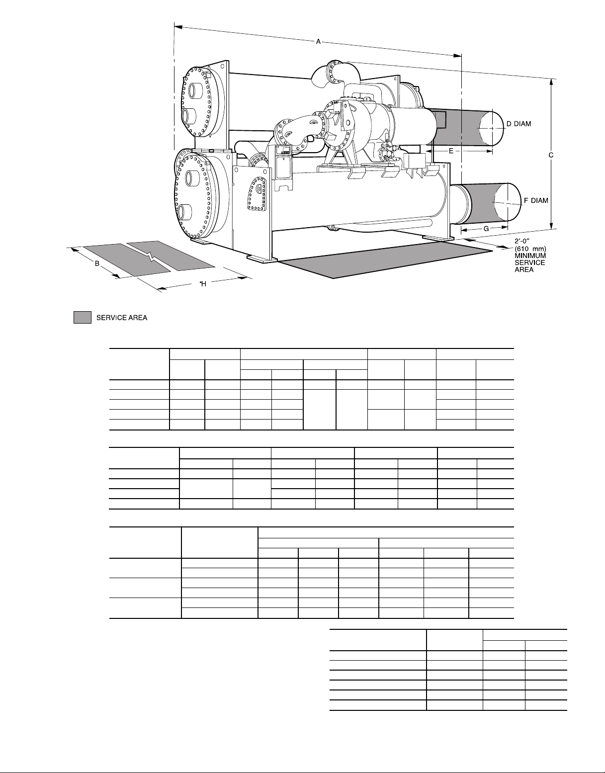
NOTES:
1. Certified drawings available upon request.
2. Service accessshould be provided perAmerican Society of Heating,Refrigeration, and Air Conditioning Engineers (ASHRAE) 15, latest edition, National Fire Protection Association (NFPA)
70, and local safety codes.
DIMENSIONS
CONDENSER
SIZE
31-33 15-6 4724 N/A N/A 8-10 2692 10-8
41-43 15-6 4724 N/A N/A
45-47 20-3 6172 12-2 3708 17- 6 5334
51-53 15-6 4724 N/A N/A
55-57 20-3 6172 12-2 3708 17- 6 5334
A (LENGTH)† B (WIDTH) C (HEIGHT) H (TUBE PULL)
ft-in. mm
17EX** 19EX
ft-in. mm ft-in. mm
1
⁄22858
9-4
ft-in. mm ft-in. mm
1
⁄23264 12-10 3912
12-2 3708
12-5 3785
12-10 3912
12-10 3912
SERVICE CLEARANCES
COMPONENT
Motor DB - DQ 1-11
Motor EA - ED
Motor EE 4- 1
Low-Side Float — — — — 2-6
D (DIAMETER)†† E (LENGTH)†† F (DIAMETER) G (LENGTH)
ft-in. mm ft-in. mm ft-in. mm ft-in. mm
1
⁄
2- 2
4
3
⁄
4
591 3- 71⁄
679
3-10
2
1
1
1105 — — — —
⁄
4
1175 — — — —
⁄
4
1251 — — — —
1
⁄
2
775 1-0 305
NOZZLE SIZES
HEAT
EXCHANGER
31-33
41-48
51-57
NOZZLE TYPE
Cooler Passes Condenser Passes
123 1 2 3
Marine 12 10 10 12 10 10
NIH 12 10 10 — 10 10
Marine 20 14 12 20 14 12
NIH 18 14 10 18 12 10
Marine — — — — 16 —
NIH — — — 20 16 —
NOZZLE SIZES (in.)|
LEGEND
NIH — Nozzle-In-Head
*Distance required for tube removal may be either end.
†Based on 2-pass, nozzle-in-head (NIH) waterboxes with 150 psi (1038 kPa)
covers.
**Overall width of units with 17 Series compressors will vary greatly depend-
ing upon the application. See the appropriate certified drawings.
††For hermetic motors (19 Series) only.
\The table at right provides additional information on nozzle sizes. Victaulic
grooves are standard for these nozzles. Optional 150 psi (1034 kPa) and
300 psi (2068 kPa) flanges are available.
¶In conformance with ASA B36.10 (American Standards Association).
Fig.9—Typical Dimensions
NOMINAL PIPE SIZE (in.) SCHEDULE¶
10 40 .365 9.27
12 Std .375 9.53
14 30 .375 9.53
16 30 .375 9.53
18 Std .375 9.53
20 20 .375 9.53
9
WALL THICKNESS
in. mm
Page 10
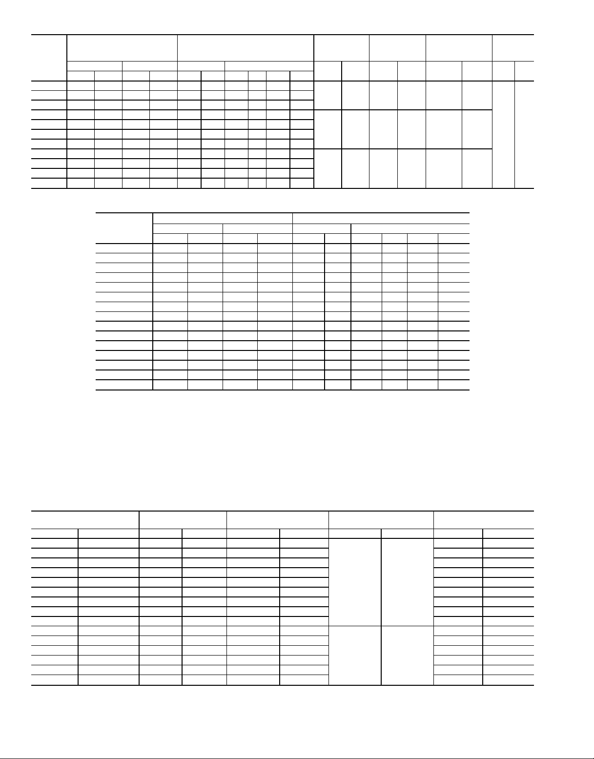
Table 1 — 17/19EX Heat Exchanger, Economizer/Storage Vessel, Piping, and Pumpout Unit Weights*
COOLER
COOLER
SIZE†
31 14,173 6 429 17,518 7 946 1,540 699 1,810 217 821 821
32 14,538 6 594 18,117 8 218 1,640 744 1,944 233 882 882
33 14,904 6 760 18,722 8 492 1,740 789 2,078 249 943 943
41 21,674 9 831 26,120 11 848 1,900 862 2,441 293 1 107 1 107
42 22,019 9 988 26,736 12 127 2,000 907 2,575 309 1 168 1 168
43 22,364 10 144 27,322 12393 2,100 953 2,709 325 1 229 1 229
44 23,841 10 814 29,836 13533 2,190 993 3,285 394 1 490 1 490
45 25,032 11 354 30,790 13966 2,260 1 025 3,006 361 1363 1 363
46 25,529 11 580 31,658 14360 2,360 1 070 3,192 383 1448 1 448
47 26,025 11 805 32,496 14740 2,460 1116 3,378 405 1 532 1 532
48 28,153 12 770 36,053 16353 2,540 1 152 4,173 500 1893 1 893
lb kg lb kg lb kg lb gal kg L
TOTAL
WEIGHT
Dry Operating†† Refrigerant Water
COOLER
CHARGE
ECONOMIZER/
STORAGE
VESSEL**
lb kg lb kg lb kg lb kg
7,169 3252 610 277 820 372
7,169 3 252 610 277 1,095 497
7,900 3 583 840 381 1,149 521
ECONOMIZER
REFRIGERANT
MISCELLANEOUS
PIPING
PUMPOUT
UNIT
210 95
CONDENSER
SIZE†
31 10,454 4 742 13,022 5 907 950 431 1,613 193 732 732
32 10,809 4 903 13,514 6 130 950 431 1,750 210 794 794
33 11,164 5 064 14,000 6 350 950 431 1,886 226 855 855
41 13,768 6 245 16,999 7711 1,090 494 2,146 257 973 973
42 14,118 6 404 17,498 7 937 1,090 494 2,282 274 1 035 1 035
43 14,468 6 563 17,978 8 155 1,090 494 2,419 290 1 097 1 097
45 16,676 7 564 20,800 9 435 1,400 635 2,720 326 1 234 1 234
46 17,172 7 789 21,489 9 747 1,400 635 2,908 348 1 319 1 319
47 17,669 8 015 22,178 10 060 1,400 635 3,096 371 1 404 1 404
51 17,188 7 796 20,993 9 522 1,100 499 2,707 325 1 228 1 228
52 17,848 8 096 21,923 9 944 1,100 499 2,964 355 1 344 1 344
53 18,400 8 346 22,682 10 288 1,100 499 3,178 381 1 442 1 442
55 20,725 9 401 25,598 11 611 1,420 644 3,453 412 1 566 1 566
56 21,663 9 826 26,896 12 199 1,420 644 3,808 457 1 727 1 727
57 22,446 10 181 27,980 12 691 1,420 644 4,105 492 1 862 1 862
*If a machine configuration other than 2-pass, 150 psig (1034 kPa), NIH waterbox configuration is used, refer to Tables 3
and 4 to obtain the additional dry and water weights that must be added to the values shown in this table.
†Cooler and condenser weights shown are based upon 2-pass, nozzle-in-head (NIH) waterboxes with 150 psig (1034 kPa)
covers. Includes components attached to cooler, but does not include suction/discharge, elbow, or other interconnecting
piping.
**Dry weight includes all components attached to economizer: Covers, float valves, brackets, control center (31 lb [14 kg]),
and power panel (20 lb [9 kg]). Dry weight does not include compressor weight, motor weight, or pumpout condensing unit
weight. The pumpout condensing unit weight is 210 lb (95 kg). For compressor and motor weights, refer to Tables 6, 7, 8,
10A, and 10B.
††Operating weight includes the sum of the dry weight, refrigerant weight, and water weight.
CONDENSER TOTAL WEIGHT CONDENSER CHARGE
Dry Operating†† Refrigerant Water
lb kg lb kg lb kg lb gal kg L
Table 2 — Refrigerant Charge
HEAT EXCHANGER SIZE COOLER CHARGE CONDENSER CHARGE ECONOMIZER CHARGE
Cooler Condenser lb kg lb kg lb kg lb kg
31 31 1540 699 950 431
32 32 1640 744 950 431 3200 1 452
33 33 1740 789 950 431 3300 1 497
41 41 1900 862 1090 494 3600 1 633
42 42 2000 907 1090 494 3700 1 678
43 43 2100 953 1090 494 3800 1 724
44 51 2190 993 1100 499 3900 1 769
44 52 2190 993 1100 499 3900 1 769
44 53 2190 993 1100 499 3900 1 769
45 45 2260 1 025 1400 635
46 46 2360 1 070 1400 635 4600 2 087
47 47 2460 1 116 1400 635 4700 2 132
48 55 2540 1 152 1420 644 4800 2 177
48 56 2540 1 152 1420 644 4800 2 177
48 57 2540 1 152 1420 644 4800 2 177
*Total machine refrigerant charge includes the cooler, condenser, and economizer.
NOTE: Regulations mandate that machine shipping charge is limited to 7500 lb (3402 kg).
610 277
844 381
TOTAL REFRIGERANT
CHARGE*
3100 1 406
4500 2 041
10
Page 11

Table 3 — Additional Cooler Weights*
COOLER
FRAME
3
4
NIH — Nozzle-In-Head
*When using a machine configuration other than 2-pass, NIH waterboxes with 150 psig (1038 kPa) covers, add the weights listed in this table to the appropriate weights
in Table 1 to obtain the correct cooler weight.
WATERBOX
TYPE
NIH 1, 3 150 1034 655 297 — — — —
NIH 1, 3 300 2068 2226 1010 — — — —
NIH 2 300 2068 1406 638 — — — —
Marine 1, 3 150 1034 780 354 3192 383 1448 1448
Marine 2 150 1034 390 177 1596 191 724 724
Marine 1, 3 300 2068 3412 1548 3192 383 1448 1448
Marine 2 300 2068 1706 774 1596 191 724 724
NIH 1, 3 150 1034 515 234 — — — —
NIH 1, 3 300 2068 2941 1334 — — — —
NIH 2 300 2068 2085 946 — — — —
Marine 1, 3 150 1034 2100 953 5102 612 2314 2314
Marine 2 150 1034 792 359 2551 306 1157 1157
Marine 1, 3 300 2068 3844 1744 5102 612 2314 2314
Marine 2 300 2068 2536 1150 2551 306 1157 1157
NUMBER
OF PASSES
DESIGN MAXIMUM
WATER PRESSURE
psig kPa lb kg lb gal kg L
ADDITIONAL
DRY WEIGHT
ADDITIONAL
WATER WEIGHT
Table 4 — Additional Condenser Weights*
COMPONENT
CONDENSER
NIH — Nozzle-In-Head
*When using a machine configuration other than 2-pass, NIH waterboxes with 150 psig (1034 kPa) covers, add the weights listed in this table to the appropriate weights
in Table 1 to obtain the correct condenser weight.
†Subtract 228 lb (103 kg) from the weight shown in Table 1.
HEAT EXCHANGER
SIZE
31-33
41-43
45-47
51-53
55-57
WATERBOX TYPE
NIH 3 150 1034 262 119 — — — —
NIH 3 300 2068 1328 602 — — — —
NIH 2 300 2068 872 396 — — — —
Marine 3 150 1034 842 382 2276 273 1032 1032
Marine 2 150 1034 421 191 1138 136 516 516
Marine 3 300 2068 1520 689 2276 273 1032 1032
Marine 2 300 2068 1099 498 1138 136 516 516
NIH 1, 3 150 1034 344 156 — — — —
NIH 1, 3 300 2068 1652 749 — — — —
NIH 2 300 2068 1132 513 — — — —
Marine 1, 3 150 1034 1692 767 3400 408 1542 1542
Marine 2 150 1034 674 306 1700 204 771 771
Marine 1, 3 300 2068 2651 1202 3400 408 1542 1542
Marine 2 300 2068 1630 739 1700 204 771 771
NIH 1 150 1034 † † — — — —
NIH 1 300 2068 1588 720 — — — —
NIH 2 300 2068 1591 721 — — — —
Marine 2 150 1034 25 11 1734 208 787 787
Marine 2 300 2068 1225 555 1734 208 787 787
NUMBER OF
PASSES
DESIGN MAXIMUM
WATER PRESSURE
psig kPa lb kg lb gal kg L
ADDITIONAL
DRY WEIGHT
ADDITIONAL
WATER WEIGHT
Table 5 — Auxiliary Connection Sizes
SIZE AND STYLE USAGE
3
⁄8in. Male Flare
1
⁄2in. FPT
1
⁄2in. NPT Conduit Power Panel Oil Pump Power Connection
1 in. NPT
1
⁄4in. FPT
1
Pumpout Condenser Refrigerant Vapor Connection
(Rupture Disc)
Pumpout Water Inlet Connection
Pumpout Water Outlet Connection
Waterbox Vent Connection
Waterbox Drain Connection
Cooler Relief Valve Connection
Economizer/Storage Vessel Connection
11
Page 12

Table6—Total 19EX Motor Weights (60 Hz)
MOTOR SIZE
DB 1484 673 1420 644 NA NA
DC 1496 678 1478 670 NA NA
DD 1514 687 1503 682 2097 951
DE 1620 728 1536 696 2152 976
DF 1657 752 1635 742 2656 1205
DG 1662 754 1677 761 2741 1243
DH 1749 793 1715 778 2806 1273
DJ 1790 812 1758 797 2876 1305
DK 1823 827 2267 1028 3054 1385
DL 2262 1026 2374 1077 3162 1434
DM 2337 1060 2501 1134 3222 1461
DN 2415 1095 2558 1160 3277 1486
DP 2456 1114 2688 1219 3402 1543
DQ NA NA 2721 1234 3467 1573
EA 1968 893 2031 921 2377 1078
EB 2128 965 2233 1013 2427 1101
EC 2241 1017 2358 1070 2602 1180
ED 2366 1073 2514 1140 2827 1282
EE 2664 1208 2989 1356 3258 1478
NA — Not Available
NOTE:Low-voltage motors are ratedbelow 600 v,medium-voltage motors range
from 600 v to 6,000 v, and high-voltage motors are rated above 6,000 v.
LOW VOLTAGE MEDIUM VOLTAGE HIGH VOLTAGE
lb kg lb kg lb kg
Table7—Total 19EX Motor Weights (50 Hz)
MOTOR SIZE
DB 1662 754 1568 711 NA NA
DC 1677 760 1628 740 NA NA
DD 1696 769 1662 754 2312 1049
DE 1710 776 1707 775 2332 1058
DF 1792 813 1807 820 2386 1082
DG 1863 845 2212 1003 2947 1337
DH 1921 871 2283 1036 3022 1371
DJ 2222 1008 2340 1061 3097 1405
DK 2331 1057 2472 1121 3187 1446
DL 2373 1076 2624 1190 3257 1477
DM 2481 1125 2692 1221 3317 1505
DN 2555 1159 2864 1299 3407 1545
DP 2597 1178 2924 1326 3502 1588
DQ NA NA 3014 1367 3612 1638
EA 2232 1012 2392 1085 2682 1217
EB 2443 1108 2380 1080 2887 1310
EC 2646 1200 2747 1246 3257 1477
ED 2760 1252 2952 1339 3442 1561
EE 3009 1365 3161 1434 3533 1603
NA — Not Available
NOTE:Low-voltage motors are ratedbelow 600 v,medium-voltage motors range
from 600 v to 6,000 v, and high-voltage motors are rated above 6,000 v.
LOW VOLTAGE MEDIUM VOLTAGE HIGH VOLTAGE
lb kg lb kg lb kg
Table 8 — Compressor Weights
COMPONENT
Compressor
Weight*
Suction
Elbow
*Weight does not include motor.
NOTES:
1. 19EX compressors include sizes −51 through −89.
2. 17/19FA5 compressors include sizes 531 through 599.
3. 19FA4 compressors include sizes 421 through 469.
19EX COMPRESSOR 17/19FA5 COMPRESSOR 19FA4
lb kg lb kg lbs kg
4886 2216 5150 2336 2625 1191
500 227 500 227 325 147
Table9—Total 17EX Drive Component Weights
MOTOR
HORSEPOWER (kW)
CODE
A 1200 544 75 34 25 11
B 1200 544 75 34 25 11
C 1200 544 75 34 25 11
D 1100 499 75 34 25 11
BASE WEIGHT COUPLING WEIGHT GUARD WEIGHT
lb kg lb kg lb kg
12
Page 13

ENCLOSURE
TYPE
Open-Drip Proof
(ODP)
Weather Protected
Type I (WPI)
Weater Protected
Type II (WPII)
Totally Enclosed
Water-To-Air Cooled
(TEWAC)
Table 10A — 17EX Motors — Total Weight, Lbs (English)
HERTZ VOLTAGE SIZE (HP)
FA (1250) FB (1500) FC (1750) FD (2000)
GA (1350) GB (1500) GC (1750) GD (2000)
HA (1250) HB (1500) HC (1750) HD (2000)
JA (1250) JB (1500) JC (1750) JD (2000)
60 Hz
50 Hz
60 Hz
50 Hz
60 Hz
50Hz
60 Hz
50 Hz
2400 4836 5721 5900 7160
3300 4824 5832 5832 7127
4160 4836 5721 5900 7160
6900 5596 6577 8776 8990
3000 5518 5878 7148 9048
3300 5518 5878 7148 9073
6300 5596 6577 8875 8976
2400 5046 5871 6050 7270
3300 5034 5982 5982 7237
4160 5046 5871 6050 7270
6900 5806 6727 8926 9100
3000 5728 6028 7298 9158
3300 5728 6028 7298 9183
6300 5806 6727 9025 9086
2400 5146 6151 6330 7600
3300 5134 6262 6262 7567
4160 5146 6151 6330 7600
6900 5906 7007 9206 9430
3000 5828 6308 7578 9488
3300 5828 6308 7578 9513
6300 5906 7007 9305 9416
2400 5707 6746 6925 8290
3300 5694 6857 6857 8257
4160 5707 6746 6925 8290
6900 6466 7602 9801 10,120
3000 6388 6903 8173 10,178
3300 6388 6903 8173 10,203
6300 6466 7602 9900 10,106
ENCLOSURE
TYPE
Open-Drip Proof
(ODP)
Weather Protected
Type I (WPI)
Weather Protected
Type II (WPII)
Totally Enclosed
Water-To-Air Cooled
(TEWAC)
Table 10B — 17EX Motors — Total Weight, Kg (SI)
FREQ VOLTAGE SIZE (kW)
FA (932) FB (1119) FC (1305) FD (1492)
GA (932) GB (1119) GC (1305) GD (1492)
HA (932) HB (1119) HC (1305) HD (1492)
JA (932) JB (1119) JC (1305) JD (1492)
60 Hz
50 Hz
60 Hz
50 Hz
60 Hz
50 Hz
60 Hz
50 Hz
2400 2194 2595 2676 3248
3300 2188 2645 2645 3233
4160 2194 2595 2676 3248
6900 2538 2983 3981 4033
3000 2503 2666 3242 4104
3300 2503 2666 3242 4116
6300 2538 2983 4026 4072
2400 2289 2663 2744 3298
3300 2283 2713 2713 3283
4160 2289 2663 2744 3298
6900 2634 3051 4049 4128
3000 2598 2734 3310 4154
3300 2598 2734 3310 4165
6300 2634 3051 4094 4121
2400 2334 2790 2871 3447
3300 2329 2840 2840 3432
4160 2334 2790 2871 3447
6900 2679 3178 4126 4277
3000 2644 2861 3437 4304
3300 2644 2861 3437 4315
6300 2679 3178 4221 4271
2400 2587 3060 3141 3760
3300 2583 3110 3110 3745
4160 2587 3060 3141 3760
6900 2933 3448 4446 4590
3000 2898 3131 3707 4617
3300 2898 3131 3707 4628
6300 2933 3448 4490 4584
13
Page 14

Table 11 — Marine Waterbox Cover Weights*
HEAT EXCHANGER
SIZE
31-33
41-48
51-57
*Heat exchangers with marine waterboxes have heavier dry and operating weights than heat exchangers with nozzle-
in-head waterboxes.
DESIGN MAXIMUM WATER PRESSURE COOLER CONDENSER
psi kPa lb kg lb kg
150 1034 1667 756 1092 495
300 2068 2280 1034 1436 651
150 1034 2236 1015 1275 579
300 2068 3060 1389 1660 754
150 1034 — — 1643 746
300 2068 — — 2243 1018
Table 12 — NIH Waterbox Cover Weights*
HEAT EXCHANGER
SIZE
31-33
41-48
51-57
NIH — Nozzle-in-Head
*The 150 psig (1034 kPa) 2-pass waterbox cover weights are included in the dry weight shown in Table 1.
†Twodifferent waterbox covers are present on 2-pass machines. The weight shown in this table represents the weight
of the waterbox cover that contains the nozzles. A blank waterbox cover is also present on 2-pass units. The weight
of the blank waterbox cover is identical to the weight of the same size marine waterbox cover. Refer to Table 11.
PASSES
DESIGN MAXIMUM WATER PRESSURE COOLER CONDENSER
psi kPa lb kg lb kg
1
2
3
1
2†
3
1
2†
3
150 1034 1880 853 — —
300 2068 2748 1247 — —
150 1034 2168 983 1356 615
300 2068 3107 1409 1959 889
150 1034 2105 955 1283 582
300 2068 2991 1357 1828 829
150 1034 2997 1361 1735 788
300 2068 4225 1918 2510 1140
150 1034 2984 1355 1885 856
300 2068 4188 1901 2590 1176
150 1034 3035 1378 1777 807
300 2068 4244 1927 2539 1153
150 1034 — — 2032 923
300 2068 — — 2940 1335
150 1034 — — 2649 1203
300 2068 — — 3640 1653
150 1034 — — — —
300 2068 — — — —
Install Machine Supports
INSTALL STANDARD ISOLATION — Figures 10 and 11
show the position of support plates and shear flex pads, which
together form the standard machine support system.
INSTALL OPTIONAL ISOLATION (if required) — Uneven floors or other considerations may dictate the use of
soleplates and leveling pads. Refer to Fig. 10 and 11.
Level machine by using jacking screws in isolation sole-
plates. Use a level at least 24 in. (600 mm) long.
For adequate and long lasting machine support, proper grout
selection and placement is essential. Carrier recommends that
only pre-mixed, epoxy-type, non-shrinking grout be used for
machine installation. Follow manufacturer’s instructions in
applying grout.
1. Check machine location prints for required grout
thickness.
2. Carefully wax jacking screws for easy removal from grout.
3. Grout must extend above the base of the soleplate and
there must be no voids in grout beneath the plates.
4. Allow grout to set and harden, per manufacturer’s instructions, before starting machine.
5. Remove jacking screws from leveling pads after grout has
hardened.
INSTALL SPRING ISOLATION — Field-supplied spring
isolators may be placed directly under machine support plates
or be located under machine soleplates. Consult job data for
specific arrangement. Low profile spring isolation assemblies are recommended so that the machine is kept at a convenient working height inside of the tube sheet.
Obtain specific details on spring mounting and machine
weight distribution from job data. Also, check job data for
methods for supporting and isolating pipes that are attached
to the spring-isolated machines.
14
Page 15

COOLER SIZES 31-33 AND 41-44
COOLER SIZES
AB C
ft-in. mm ft-in. mm ft-in. mm
31-33 8-8
2
2654 8-10 2692 4- 8 1422
1
⁄
41-44 9-3 2819 9- 4
COOLER SIZES 45-48
DIMENSIONS
1
⁄
2
2858 4-111⁄
4
1505
NOTES:
1. Dimensions in ( ) are in mm.
2. 1 inch = 25.4 mm.
3. All dimensions approximately ±
1
⁄2inch.
Fig. 10 — Machine Contact Surfaces
15
Page 16

SOLEPLATE ISOLATION TYPICAL ISOLATION
ACCESSORY ISOLATION
SOLEPLATE DETAIL
SECTION A-A
NOTES:
1. Dimensions in ( ) are in millimeters.
2. Accessory soleplate package includes 4 soleplates, 16 jacking screws and leveling pads. Requires
isolation package.
3. Jacking screws to be removed after grout has set.
4. Thickness of grout will vary,depending on the amount necessary to level chiller. Use only pre-mixed
non-shrinking grout, Celcote HT-648 or Master Builders 636, 08-1
1
⁄29 (38.1) to 08-21⁄49 (57) thick.
STANDARD ISOLATION
VIEW B-B
ISOLATION WITH ISOLATION PACKAGE ONLY
(STANDARD)
NOTE: Isolation package includes 4 shear flex pads.
Fig. 11 — Machine Vibration Isolation
16
Page 17

Connect Piping
INSTALL WATER PIPING TO HEAT EXCHANGERS —
Install piping using job data, piping drawings, and procedure outlined below. A typical piping installation is shown
in Fig. 12.
Factory-supplied insulation is not flammable but can be
damaged by welding sparks and open flame. Protect insulation with a wet canvas cover.
Remove chilled and condenser water sensors before
welding connecting piping to water nozzles. Refer to
Fig. 2 and 3. Replace sensors after welding is complete.
1. If the machine is a nozzle-in-head (NIH) arrangement,
offset pipe flanges to permit removal of waterbox cover
for maintenance and to provide clearance for pipe cleaning. See Tables 11 and 12 for waterbox cover weights.
No flanges are necessary with marine waterboxes; however, water piping should not cross in front of the waterbox or access will be blocked off.
2. Provide openings in water piping for required pressure
gages and thermometers. Openings should be at least 6 to
10 pipe diameters from the waterbox nozzle. For thorough mixing and temperature stabilization, wells in the
leaving water pipe should extend inside pipe at least
2 in. (50 mm).
3. Install air vents at all high points in piping to remove air
and prevent water hammer.
4. Install pipe hangers where needed. Make sure no weight
or stress is placed on waterbox nozzles or flanges.
5. Water flow direction must be as specified in Fig. 13.
NOTE: Entering water is always the lower of the 2 nozzles.
Leaving water is always the upper nozzle for cooler or
condenser.
6. Water flow switches must be of vapor-tight construction
and must be installed on top of pipe in a horizontal run
and at least 5 pipe diameters from any bend.
Differential pressure type flow switches may be connected at the nozzle of the waterbox.
7. Install waterbox vent and drain piping in accordance with
individual job data. All connections are3⁄4-in. FPT.
8. Install waterbox drain plugs in the unused waterbox drains
and vent openings.
9. Install water piping to the optional pumpout system condenser storage tank as shown in Fig. 14.
LEGEND
COM — Common
N.O. — Normally Open
*Donot locate pressure connections past the machineisolation valve.
Fig. 12 — Typical Nozzle Piping
17
Page 18

NOZZLE-IN-HEAD WATERBOXES
FRAME 3 AND 5 MARINE WATERBOXES
COOLER WATERBOX
Pass In Out
1
2
3
Pass In Out
1
2
3
NOTES:
1. Frame 5 condenser available in 1 and 2
pass only. Frame 3 in 2 and 3 pass only.
2. The vents for these waterboxes, located
in the covers are 1 in. FPT at the top of
each box, and the drains are 1 in. FPT,at
the bottom.
3. Victaulic connections are standard.
4. Flanged waterbox connections are
optional.
85 A
58 B
79 C
46 D
76 E
49 F
CONDENSER WATERBOX
11 2 P
211 Q
10 12 R
13 S
10 3 T
112 U
Arr.
Code
Arr.
Code
Fig. 13 — Nozzle Arrangements
COOLER WATERBOX
Pass In Out
1
2
3
Pass In Out
2
3
NOTES:
1. Frame 3 condenser available in 2 and 3
pass only.Frame 5 condenser available in
2 pass only.
2. The vents for these waterboxes are
1 in. FPT at the top of each box, and the
drains are 1 in. FPT, at the bottom.
3. Victaulic connections are standard.
4. Flanged waterbox connections are
optional.
85 A
58 B
79 C
46 D
16 17 G
76 E
49 F
CONDENSER WATERBOX
10 12 R
13 S
13 15 Y
10 3 T
112 U
Arr.
Code
Arr.
Code
18
Page 19

FRAME 4 MARINE WATERBOXES
NOTES:
1. The vents for these waterboxes are 1 in. FPT at the top of each box. The
drains are 1 in. FPT, at the bottom.
2. Victaulic connections are standard.
3. Flanged connections are optional.
COOLER WATERBOX
Pass In Out
1
2
3
Pass In Out
1
2
3
85 A
58 B
79 C
46 D
16 17 G
76 E
49 F
CONDENSER WATERBOX
11 2 P
211 Q
10 12 R
13 S
13 15 Y
10 3 T
112 U
Arr.
Code
Arr.
Code
Fig. 13 — Nozzle Arrangements (cont)
Fig. 14 — Pumpout Unit
INSTALL WATER TO OIL COOLER ON FA COMPRESORS — On FAcompressors, water must be piped to the oil
cooler heat exchanger (located under the suction pipe to the
compressor). The water supply may be either city water or
chilled water. Pipe city water to an open sight drain. Chilled
water enters via the cooling entering water intake (Fig. 15).
City water must be clean and noncorrosive. Water side
erosion or corrosion of the oil cooler coil may lead to
extensive machine damage not covered by the standard
warranty.
If water from the machine chilled water circuit is used for
oil cooling, it should enter the oil cooler from the entering
water line of the machine cooler. Water leaving the oil cooler
should connect to the leaving water line of the machine cooler
at a point downstream from the chilled water sensor, so that
oil cooler leaving water temperature does not affect the sensor readings.
Locate the oil cooler leaving water connection at some
distance from any water temperature indicators. On singlepass machines, water leaving the oil cooler should be connected into the suction side of the chilled water pump so that
adequate pressure drop is assured for oil cooling.
The nominal conditions for oil cooler water flow are:
Flow rate .......................30gpm(1.9 L/s)
Leaving temperature ........85to100F(29to38C)
Pressure drop at oil cooler .......7.25 psid (50 kPad)
Max differential pressure across closed
solenoid valve ..............150psid (1034 kPad)
1
The oil cooler connections are 1
⁄4in. FPT.
19
Page 20

Fig. 15 — Water Piping, Oil Cooler to
Chilled Water Circuit (Typical)
INSTALL VENT PIPING TO RELIEF DEVICES — The
17/19EX chiller is factory equipped with relief devices on
the cooler and utility vessels. Refer to Fig. 2 and 3, and
Table 13 for size and location of relief devices, as well as
information that will help determine pipe size. Vent relief
devices to the outdoors in accordance with ASHRAE 15
(latest edition) Safety Code for Mechanical Refrigeration and
all other applicable codes. Toensure relief valve serviceability, and as required in ASHRAE 15, latest edition, 3-way
dual shutoff valves and redundant relief valves are installed
on the economizer/storage vessel, refer to Fig. 16.
NOTE: The 3-way dual shutoff valve should be either front
seated or back seated. Running the refrigeration system with
the valve stem in the center position can reduce total relief
capacity and cause valve chattering.
Refrigerant discharged into confined spaces can displace oxygen and cause asphyxiation.
1. If relief device piping is manifolded, the cross-sectional
area of the relief pipe must at least equal the sum of the
areas required for individual relief pipes.
2. Provide a pipe plug near outlet side of each relief device
for leak testing. Provide pipe fittings that allow vent piping to be disconnected periodically for inspection of valve
mechanism.
3. Piping to relief devices must not apply stress to the
device. Adequately support piping. A length of flexible
tubing or piping near the device is essential on springisolated machines.
4. Cover the outdoor vent with a rain cap and place a condensation drain at the low point in the vent piping to prevent water build-up on the atmospheric side of the relief
device.
Make Electrical Connections — Field wiring must
be installed in accordance with job wiring diagrams and all
applicable electrical codes.
Fig. 16 — Typical 17/19EX Utility Vessel
Relief Valve Tee
Do not run 120-v wiring into the control center. The
control center should only be used for additional extra
low-voltage wiring (50 v maximum).
Wiring diagrams in this publication (Fig. 17-23) are for
reference only and are not intended for use during actual installation; follow job specific wiring diagrams.
Specific electrical ratings for individual components are
shown in Table 14.
Do not attempt to start compressor or oil pump — even
for a rotation check — or apply test voltage of any kind
while machine is under dehydration vacuum. Motor insulation breakdown and serious damage may result.
CONNECT CONTROL INPUTS — Connect the control input wiring from the chilled and condenser water flow switches
to the starter terminal strip. Wiring may also be specified for
a spare safety switch, and a remote start/stop contact can be
wired to the starter terminal strip, as shown in Fig. 17 and
18. Additional spare sensors and Carrier Comfort Network
modules may be specified as well. These are wired to the
machine control center as indicated in Fig. 22 and 23.
CONNECT CONTROL OUTPUTS — Connect auxiliary
equipment, chilled and condenser water pumps, and spare
alarms as required and indicated on job wiring drawings.
Connect Starter — Assemble and install compressor terminal box in desired orientation, and cut necessary conduit openings in conduit support plates. Attach power leads to compressor terminals in accordance with job wiring drawings,
observing caution label in terminal box. Use only copper conductors. The motor must be grounded in accordance with
NEC (National Electrical Code), applicable local codes, and
job wiring diagrams.
IMPORTANT: Do not insulate terminals until wiring
arrangement has been checked and approved by
Carrier start-up personnel.Also, make sure correct phasing is followed for proper motor rotation.
20
Page 21

Insulate Motor Terminals and Lead Wire Ends — Insulate
compressor motor terminals, lead wire ends, and electrical
wires to prevent moisture condensation and electrical arcing. For low-voltage units (up to 600 v), insulate the electrical terminals as follows:
1. Insulate each terminal by wrapping with one layer of
insulation putty.
2. Overwrap putty with 4 layers of vinyl tape.
High-voltage units require special terminal preparation. The
vinyl tape is not acceptable; a high voltage tape must be used.
Installer is responsible for any damage caused by improper
wiring between starter and compressor motor.
Connect Power Wiresto Oil Pump Contactor — Connect power
wires to oil pump contactor mounted in machine power panel.
(See Fig. 19.) Use the electrical disconnect located in the
machine starter (if supplied), or a separate fused disconnect
as shown on job wiring diagrams. Check that power supply
voltage agrees with oil pump voltage. Follow correct phasing for proper motor rotation.
Do notwire into the top surface of the power panel. Knockouts are provided on the underside of the panel.
Table 13 — Relief Valve Locations and Data
Connect Power Wires to Oil Heater Contactor — Connect
control power wiring between the oil heater contactor terminals (Fig. 17 and 18) and terminals LL1 and LL2 on the
field wiring strip in the compressor motor starter. Refer to
Fig. 21 and wiring label on the chiller power panel.
Voltage to terminals LL1 and LL2 comes from a control transformer in a starter built to Carrier specifications. Do not connect an outside source of control power
to the compressor motor starter (terminals LL1 and LL2).
An outside power source will produce dangerous voltage at the line side of the starter, because supplying voltage at the transformer secondary terminals produces input level voltage at the transformer primary terminals.
Connect Communication and Control Wiring from Starter to
Power Panel — Connect control wiring from main motor starter
to the chiller power panel. All control wiring must use shielded
cable. Also connect the communications cable. Make sure
the control circuit is grounded in accordance with applicable
electrical codes and instructions on chiller control wiring
label.
RELIEF VALVE
LOCATION
Cooler
Economizer/Storage
Pumpout Unit Condenser ALL ALL 1.5 0.01
*To ensure relief valve serviceability, and as required in ASHRAE 15,
latest edition, three-way valves and redundant relief valves are installed on the storage vessel. Only one half of the ‘‘No. of Valves’’
listed are in service at any time.
NOTES:
1. Thecooler relief C-factor is forboth cooler and condenser vented
through the cooler in accordance with ASHRAE (American
Society of Heating, Refrigeration, and Air Conditioning Engineers) 15, latest edition.
Vessel
HEAT EXCHANGER
SIZE
Cooler Condenser lb air/min. kg air/sec. psig kPa
31-33 31-33 139.7 1.06 1
41-43 41-43 158.8 1.20 1
44 51-53 164.6 1.24 1
45-47 45-47 216.3 1.64 1
48 55-57 228.5 1.73 1
41-44 ALL 64.2 0.49 1
45-48 ALL 84.3 0.64 1
REQUIRED C FACTOR
NOMINAL OUTLET
PIPE SIZE (in.)
1
⁄4FPT 2 225 1551
1
⁄4FPT 2 225 1551
1
⁄4FPT 2 225 1551
1
⁄4FPT 3 225 1551
1
⁄4NPT 3 225 1551
1
⁄4NPT 2* 225 1551
1
3
2. Relief valve discharge pipe sizing is to be calculated per latest
version of ASHRAE 15, using the tabulated C-factors and nominal pipe size listed above. Cooler and economizer/storage vessel rated relief valve pressure is 225 psig (1551 kPa).
3. The pumpout unit condenser contains less than 110lb (50 kg) of
HFC-134a,which isa GroupA1 refrigerant.TheASHRAE15 standard exempts small-volume vessels from the requirement to vent
outside. However, Carrier recommends that the pumpout condenser be connected to the rest of the vent system.
⁄4FPT 2* 225 1551
⁄8in. Male Flare MPT 1 385 2655
NUMBER OF
VALVES
RATED RELIEF
PRESSURE
21
Page 22

Table 14 — Individual Component Ratings
POWER SOURCE ITEM AVERAGE kW
Seal Leakage
1*
(17EX Only)
1†
2† Oil Pump
1**
3**
(Optional)
LEGEND
FLA — Full Load Amps
LRA — Locked Rotor Amps
*Available for 17EX machines only.
†Available for 17/19EX machines.
**Available as an option on 17/19EX machines.
Pump
Motor Space
Heater
Control Module
and Actuator
Oil Sump Heater 1.00 115
Hot Gas
Bypass
Pumpout
Compressor
0.23 115 115-1-50/60 4.78 21.7
0.50 115 115-1-50/60 4.35 4.35
0.40 115
1.35 220 200/240-3-60 4.32 24.5
1.30 430 380/480-3-60 2.15 12.2
1.37 563 507/619-3-60 2.13 25.0
1.49 230 220/240-3-50 4.83 28.0
1.49 393 346/440-3-50 2.59 12.2
0.20 115 115-1-50/60 2.00 4.75
3.41
DESIGN CENTER
VOLTAGE
204 200/208-3-60 10.90 63.5
230 220/240-3-60 9.50 57.5
460 440/480-3-60 4.70 28.8
575 550/600-3-60 3.80 23.0
400 380/415-3-50 4.70 28.8
NOTE: The oil pump is powered through a field wiring terminal into
the power panel. Power to the controls and oil heater via the power
panel must be on circuits that can provide continuous service when
the compressor starter is disconnected.
SUPPLY
V-PH-HZ
115-1-60
115-1-50
115-1-60
115-1-50
FLA LRA
3.50 —
8.70 —
22
Page 23

*Indicates chilled water pump control contacts or run status contacts.
†Indicates condenser water pump control contacts.
**Indicates tower fan relay contacts.
††Indicates circuit breaker shunt trip contacts.
\ Indicates remote alarm contacts.
NOTES:
I. GENERAL
1.0 Starters shall be designed and manufactured in accordance with Carrier Engineering Requirement Z-375.
1.1 All field-supplied conductors, devices, field-installation wiring, and termination ofconductors and devices, must be in compliance with all applicable codes and job specifications.
1.2 The routing of field-installed conduit and conductors and the location of fieldinstalled devices must not interfere with equipment access or the reading, adjusting,
or servicing of any component.
1.3 Equipment, installation, and all starting and control devices must comply with details in equipment submittal drawings and literature.
1.4 Contacts and switches are shown in the position they would assume with the circuit
deenergized and the chiller shut down.
1.5 WARNING — Do not use aluminum conductors.
1.6 Installer is responsible for any damage caused by improper wiring between starter
and machine.
II. POWER WIRING TO STARTER
2.0 Power conductor rating must meet minimum unit nameplate voltage and compressor motor RLA.
When (3) conductors are used:
Minimum ampacity per conductor = 1.25 x compressor RLA
When (6) conductors are used for Wye-Delta starting:
Minimum ampacity per conductor = 0.721 x compressor RLA
2.1 Lug adapters may be required if installation conditions dictate that conductors be
sized beyond the minimum ampacity required. Contact starter supplier for lug
information.
2.2 Compressor motor and controls must be grounded by using equipment grounding
lugs provided inside starter enclosure.
III. CONTROL WIRING
3.0 Field supplied control conductors to be at least 18 AWG or larger.
3.1 Chilled water and condenser water flow switch contacts, optional remote start device contacts and optional spare safety device contacts must have 24 vdc rating.
Max current is 60 ma, nominal current is 10 ma. Switches with gold plated bifurcated contacts are recommended.
3.2 Remove jumper wire between 12A and 12B before connecting auxiliary safeties between these terminals.
3.3 Pilot relays can control cooler and condenser pump and tower fan motor contactor
coil loads rated 10 amps at 115vacupto 3 amps at 600 vac. Control wiring required
for Carrier to start pumps and tower fan motors must be provided to assure
machine protection. If primary pump and tower fan motor are controlled by other
means, also provide a parallel means for control by Carrier. Do not use starter control transformer as the power source for pilot relay loads.
Fig. 17 — Typical Field Wiring (Low-Voltage Motors) with Free-Standing Starter
LEGEND
Required Power Wiring
Required Control Wiring
SMM — Starter Management Module
IV. POWER WIRING BETWEEN STARTERAND COMPRESSOR MOTOR
Options Wiring
3.4 Do not route control wiring carrying 30 v or less within a conduit which has wires
carrying 50 v or higher or along side wires carrying 50 v or higher.
3.5 Voltage selector switch in machine power panel isfactorysetfor 115vcontrolpower
source. Do not use the 230 v position. If this switch is set to 230 v position, the oil
heater will not operate.
3.6 Control wiring cables between starter and power panel must be shielded with minimum rating of 600 v, 80 C ground shield at starter. Wires A,B, and C are communication wires and must be run in a separate cable.
3.7 If optional oil pump circuit breaker is not supplied within the starter enclosure as
shown, it must be located within sight of the machine with wiring routed to suit.
3.8 Voltage to terminals LL1 and LL2 comes from a control transformer in a starter built
to Carrier specifications. Do not connect an outside source of control power to the
compressor motor starter (terminals LL1 and LL2). An outside power source will
produce dangerous voltage at the line sideof the starter,because supplying voltage
at the transformer secondary terminals produces input level voltage at the transformer primary terminals.
4.0 Low voltage (600 v or less) compressor motors have (6),5⁄8in. terminal studs (lead
connectors not supplied by Carrier). Either 3 or 6 leads must be run between compressor motor and starter, depending on type of motor starter employed. If only 3
leads are required, jumper motor terminals as follows: 1 to 6, 2 to 4, 3 to 5. Center
tocenter distance between terminals is 2
have nameplate stamped as to conforming with Carrier requirement Z-375. Medium
voltage (over 600 v) compressor motors have (3) terminals. Connections out of terminals are 3 in. long stranded wire pigtails, #4 AWG, strand wire for all medium
voltage motor sizes. Distance between terminal is 7
connectorsandinsulationforhighvoltagealternatingcurrentcableterminations(these
items are not supplied by Carrier). Compressor motor starter must have nameplate
stamped as to conforming with Carrier requirement Z-375.
4.1 When more than one conduit is used to run conductors from starter to compressor
motor terminal box, one conductor from each phase must be in each conduit to
prevent excessive heating. (e.g., conductors to motor terminals 1, 2 and 3 in one
conduit, and those to 4, 5 and 6 in another.)
4.2 Compressor motor power connections can be made through top, top rear or sides
of compressor motor terminal box using holes cut bycontractor to suit conduit. Flexible conduit should be used for the last few feet to the terminal box for unit vibration
isolation. Use of stress cones or 12 conductors larger than 500 MCM may require
an oversize (special) motor terminal box (not supplied by Carrier). Lead connections between 3-phase motors and their starters must not be insulated until Carrier
personnel have checked compressor and oil pump rotations.
4.3 Compressor motor frame to be grounded in accordance with the National Electrical
Code (NFPA-70) and applicable codes. Means for grounding compressor motor is
a pressure connector for #4 to 500 MCM wire, supplied and located in the back
lower left side corner of the compressor motor terminal box.
4.4 Do not allow motor terminals to support weight of wire cables. Use cable supports
and strain reliefs as required.
4.5 Use backup wrench when tightening lead connectors to motorterminalstuds.Torque
to 45 lb-ft max.
15
⁄16inches.Compressor motor starter must
9
⁄16inches. Use suitable splice
23
Page 24

Notes on following page.
LEGEND
PIC — Product Integrated Control
SMM — Starter Management Module
Required Power Wiring
Required Control Wiring
Options Wiring
Fig. 18 — Field Wiring (High Voltage Motors) with Optional Free-Standing Starter
24
Page 25

NOTES:
I GENERAL
1.0 Starters shall be designed and manufactured in accordance with
Carrier Engineering requirement Z-375.
1.1 All field-supplied conductors, devices and the field-installation wiring,
termination of conductors and devices, must be in compliance with all
applicable codes and job specifications.
1.2 The routing of field-installed conduit and conductors and the location of
field-installed devices, must not interfere with equipment access of the
reading, adjusting, or servicing of any component.
1.3 Equipment installation and all starting and control devices must comply
with details in equipment submittal drawings and literature.
1.4 Contacts and switches are shown in the position they would assume
with the circuit deenergized and the chiller shut down.
1.5 WARNING: Do not use aluminum conductors.
1.6 Installer is responsible for any damage caused by improper wiring between starter and machine.
II POWER WIRING TO STARTER
2.0 Power conductor rating must meet minimum unit nameplate voltage
and compressor motor RLA (rated load amps). When (3) conductors
are used:
Minimum ampacity per conductor =1.25 x compressor RLA
When (6) conductors are used:
Minimum ampacity per conductor =0.721 x compressor RLA.
2.1 Lug adaptersmay be required if installation conditions dictate thatconductorsbe sized beyond the minimumampacity required. Contact starter
supplier for lug information.
2.2 Compressor motor and controls must be grounded by using equipment grounding lugs provided inside starter enclosure.
III CONTROL WIRING
3.0 Field supplied control conductors to be at least 18AWG(AmericanWire
Gage), or larger.
3.1 Chilled water and condenser water flow switch contacts, optional remote start device contacts, and optional spare safety device contacts
must have 24 vdc rating. Maximum current is 60 ma, nominal current
is 10 ma. Switches with gold plated bifurcated contacts are
recommended.
3.2 Remove jumper wire between 12A and 12B before connecting auxiliary
safeties between these terminals.
3.3 Maximum loadon pilot relays is 10amps. Pilot relays can control cooler
and condenser pump and tower fan motor contactor coil loads rated up
to 10 amps at 115 vac or up to 3 amps at 600 vac. Control wiring required for Carrier to start pumps and tower fan motors must be provided to assure machine protection. If primary pump and tower motor
control is by other means, also provide a parallel means for control by
Carrier. Do not use starter control transformer as the power source for
pilot relay loads.
3.4 Do not route control wiring carrying 30 v or less within a conduit which
has wires carrying 50 v or higher or along side wires carrying 50 v or
higher.
3.5 Voltage selector switch in machine power panel is factory set for
115 v control and oil heater power source. The 230 v position is not
used. If switch is set to 230 v position, oil heater will not operate.
3.6 Control wiring cablesbetween starter and powerpanel must be shielded
with minimum rating of 600 v, 80 C. Ground shield at starter. Wires A,
B, and C arecommunication wires and must be run ina separate cable.
3.7 If optional oil pump circuit breaker is not supplied within the starter enclosure as shown, it must be located within sight of the machine with
wiring routed to suit.
3.8 Voltage to terminals LL1 and LL2 comes from a control transformer in
astarter built to Carrierspecifications. Do not connectan outside source
of control power to the compressor motor starter (terminals LL1 and
LL2). An outside power source will produce dangerous voltage at the
line side of the starter, because supplying voltage at the transformer
secondary terminals produces inputlevel voltage at the transformer primary terminals.
IV POWER WIRING BETWEEN STARTER AND COMPRESSOR MOTOR
4.0 Medium voltage (over 600 volts) hermetic compressor motors have
3 terminals. Use no. 4 AWG strand wires for all medium and high voltage hermetic motors. Distance between terminal is 7
suitable splice connectors and insulation for high-voltage alternating
current cable terminations (these items are not supplied by Carrier).
Compressor motor starter must have nameplate stamped as to conforming with Carrier requirement Z-375. Medium voltage open motors
have lug terminations (see certified drawings for size).
4.1 When more than one conduit is used to run conductors from starter to
compressor motor terminal box, one conductor from each phase must
be in each conduit, to prevent excessive heating, (e.g., conductors to
motor terminals 1, 2, and 3 in one conduit, and those to 1, 2, and 3 in
another).
4.2 Compressor motor power connections can be made through top, top
rear, or sides of compressor motor terminal box by using holes cut by
contractor to suit conduit. Flexible conduit should be used for the last
few feet to the terminal box for unit vibration isolation. Use of stress
cones may require an oversize (special) motor terminal box (not supplied by Carrier).
4.3 Compressor motor frame to be grounded in accordance with the NationalElectrical Code (NFPA-70)andapplicablecodes. Means for grounding compressor motor is a no. 4 AWG, 500 MCM pressure connector,
supplied and located in the lower left side corner of the compressor
motor terminal box.
4.4 Do not allow motor terminals to support weight of wire cables, use
cable supports and strain reliefs as required.
9
⁄16inches. Use
Fig. 18 — Field Wiring (High Voltage Motors) with Optional Free-Standing Starter (cont)
25
Page 26

LEGEND
Factory Wiring
Field Wiring
Oil Pump Terminal
Power Panel Component Terminal
Fig. 19 — Oil Pump Wiring
LEGEND
1—Chilled Water Pump Starter
2—Condenser Water Pump Starter
3—Cooling Tower Fan Starter
4—Condenser Water Pump
5—Chilled Water Pump
6—Disconnect
7—Oil Pump Disconnect (See Note 5)
8—Free-Standing Compressor Motor Starter
9—Chiller Auxiliary Power Panel
Piping
Control Wiring
Power Wiring
Fig. 20 — 17/19EX with Free-Standing Starter
19EX SHOWN
NOTES:
1. Wiring and piping shown are for general point-of-connection only
2. All wiring must comply with applicable codes.
3. Refer to Carrier System Design Manual for details regarding pip-
4. Wiring not shown for optional devices such as:
5. Oil pump disconnect may be located within the enclosure of Item
6. Water piping to the oil cooler is required on FA compressors.
26
and are not intended to show details fora specific installation. Certified field wiring and dimensional diagrams are available on request.
ing techniques.
• Remote Start-Stop
• Remote Alarms
• Optional Safety Device
• 4 to 20 mA Resets
• Optional Remote Sensors
8 — Free-Standing Compressor Motor Starter.
Page 27

LEGEND
Field Wiring
Power Panel Component Terminal
Fig. 21 — Oil Heater and Control Power Wiring
temperature range of −4 F to 140 F (−20 C to 60 C) is
required. See table below for cables that meet the
requirements.
MANUFACTURER CABLE NO.
Alpha 2413 or 5463
American A22503
Belden 8772
Columbia 02525
When connecting the CCN communication bus to a system element, a color code system for the entire network is
recommended to simplify installation and checkout. The following color code is recommended:
Fig. 22 — Carrier Comfort Network
Communication Bus Wiring
CARRIER COMFORT NETWORK INTERFACE — The
Carrier Comfort Network (CCN) communication bus wiring
is supplied and installed by the electrical contractor (if required by jobsite prints). It consists of shielded, 3-conductor
cable with drain wire.
The system elements are connected to the communication
bus in a daisy chain arrangement. The positive pin of each
system element communication connector must be wired to
the positive pins of the system element on either side of it.
The negative pins must be wired to the negative pins. The
signal ground pins must be wired to the signal ground pins.
See Fig. 23 for location of the CCN network connector
(COMM1) on the processor module.
NOTE: Conductors and drain wire must be 20 AWG
(American WireGage) minimum stranded, tinned copper. Individual conductors must be insulated with PVC, PVC/
nylon, vinyl, Teflon, or polyethylene. An aluminum/ polyester 100% foil shield and an outer jacket of PVC, PVC/
nylon, chrome vinyl, or Teflon with a minimum operating
SIGNAL TYPE
+ Red 1
Ground White 2
− Black 3
CCN BUS CONDUCTOR
INSULATION COLOR
COMM1 PLUG
PIN NO.
If a cable with a different color scheme is selected, a
similar color code should be adopted for the entire network.
At each system element, the shields of its communication
bus cables must be tied together. If the communication bus
is entirely within one building, the resulting continuous shield
must be connected to ground at only one single point. See
Fig. 23. If the communication bus cable exits from one building and enters another, the shields must be connected to ground
at the lightning suppressor in each building where the cable
enters or exits the building (one point only).
To connect the 17/19EX chiller to the network, proceed
as follows (Fig. 23):
1. Cut power to the PIC (Product Integrated Control) panel.
2. Remove the COMM1 plug from the processor module.
3. Cut a CCN wire and strip the ends of the RED, WHITE,
and BLACK conductors.
4. Using a wirenut, connect the drain wires together.
5. Insert and secure the RED wire to Terminal 1 of the
COMM1 plug.
6. Insert and secure the WHITE wire to Terminal 2 of the
COMM1 plug.
7. Insert and secure the BLACK wire to Terminal 3 of the
COMM1 plug.
8. Attach the COMM1 plug back onto the processor
module.
9. Mount a terminal strip in a convenient location.
10. Connect the opposite ends of each conductor to separate
terminals on the terminal strip.
11. Attach the CCN Network wiring:
a. Connect the RED wire to the matching location on
the terminal strip.
b. Connect the WHITE wire to the matching location
on the terminal strip.
c. Connect the BLACK wire to the matching location
on the terminal strip.
27
Page 28

Install Field Insulation
Protect insulation from weld heat damage and weld splatter. Cover with wet canvas cover during water piping
installation.
When installing insulation at the job site, insulate the fol-
lowing components (see Fig. 24 and Table 15):
• compressor motor
• cooler shell
• cooler tube sheets
• suction piping
• motor cooling drain
• oil cooler refrigerant side tubing
• utility vessel (low side)
Additional insulation of condenser and compressor com-
ponents and lines may be necessary to prevent condensation
on these components.
NOTE: Carrier does not provide waterbox insulation. Insulation of the waterbox covers must be field supplied at the
jobsite. When insulating the waterbox covers, allow enough
room for removal of the waterbox covers during servicing.
FACTORY INSULATION (OPTIONAL) — Optional
factory insulation is available for the evaporator shell and
tube sheets, suction pipe, compressor motors, and refrigerant drain line(s). Insulation applied at the factory is
(19.0 mm) thick and has a thermal conductivity K value of
● in. W
0.28 (0.0404 °C). Insulation conforms
Btu
hr
● ft2● °F
m
with UL Standard 94, Classification 94 HBF.
3
⁄4in.
Table 15 — Insulation Requirements
Sheet Foam Insulation
2
COMPONENT
Cooler Shell (Sizes 31-33) 254 23.6
Cooler Shell (Sizes 41-44) 306 28.4
Cooler Shell (Sizes 45-48) 374 34.7
Economizer Low Side Float Chamber 48 4.5
Economizer Main Shell (with cooler sizes 31-44) 85 7.9
Economizer Main Shell (with cooler sizes 45-48) 115 10.1
Suction Line 25 2.3
Cooler Marine Waterbox (1 or 3 pass, with
frame-3 coolers)
Cooler Marine Waterbox (2 pass, with
frame-3 coolers)
Cooler Marine Waterbox (1 or 3 pass, with
frame-4 coolers)
Cooler Marine Waterbox (2 pass, with
frame-4 coolers)
Cooler NIH Waterbox (with frame-3 coolers) 74 6.9
Cooler NIH Waterbox (with frame-4 coolers) 88 8.2
Main Motor Shell (with −51 through −89
compressors)
Main Motor Shell (with 421 through 469 compressors) 27 2.5
Main Motor Shell (with 531 through 599 compressors) 41 3.8
Foam Tubing Insulation
TYPE Ft m
1
⁄8( Foam Tubing 9 2.7
1
5
⁄8( Foam Tubing 2 0.6
1
2( Foam Tubing 9 2.7
5( Foam Tubing 14 4.3
NOTES:
1. Cooler value includes marine waterbox on one end (even-pass
arrangement).
2. Values are approximate.
3. Thermal insulation is available as a factory-installed option. Waterbox insulation must be field supplied.
ft
m
126 11.7
100 9.3
158 14.7
123 11.4
27 2.5
2
28
Page 29

19EX CHILLERS
LEGEND
Factory Wiring
Field Wiring
*Field-supplied terminal strip must be located in the control center.
†Switches S1 and S2 are factory set on PSIO modules. Do not alter the switches.
Fig. 23 — COMM1 CCN Communication Wiring for Multiple 17/19EX Chillers (Typical)
29
Page 30

FRONT VIEW
PLAN VIEW
— Area must be factory or field insulated
— Area to be field insulated, if ambient conditions require.
NOTE: Waterbox covers are to be insulated by the contractor.
IMPORTANT: 17EX insulation is identical to the 19EX insulation shown
above. 17EX motors do not require insulation.
Fig. 24 — Typical Insulation Area (19EX Shown)
Copyright 1996 Carrier Corporation
Manufacturer reserves the right to discontinue, or change at any time, specifications or designs without notice and without incurring obligations.
Book 2 2
Tab 5a 5d
PC 211 Catalog No. 531-749 Printed in U.S.A. Form 17/19EX-2SI Pg 30 3-96 Replaces: 17/19EX-1SI
Page 31

INSTALLATION START-UP REQUEST CHECKLIST
Machine Model Number: 17/19EX Serial Number:
To:
Attn:
The following information provides the status of the chiller installation.
1. The machine is level.
2. The machine components are installed and connected in
accordance with the installation instructions.
3. The isolation package and grouting (if necessary)
are installed.
4. The relief valves are piped to the atmosphere.
5. All piping is installed and supported. Direction of flow
is indicated in accordance with the installation instructions
and job prints.
a. Chilled water piping
b. Condenser water piping
c. Waterbox drain piping
d. Pumpout unit condenser piping (if installed)
e. Oil cooler water piping (FA compressors only)
f. Other
6. Gages are installed as called for on the job prints required
to establish design flow for the cooler and condenser.
a. Water pressure gages IN and OUT
b. Water temperature gages IN and OUT
7. The machine’s starter wiring is complete. The wiring is
installed per installation instructions and certified prints.
a. Power wiring to compressor motor. (Motor leads will
not be taped until the Carrier technician megger tests
the motor.)
b. Oil pump wiring
c. Oil heater/control wiring
d. Other
8. The motor starter has not been supplied by Carrier. It
has been installed according to the manufacturer’s
instructions.
9. The motor starter has not been supplied by Carrier and it
has been checked for proper operation.
COMMENTS:
Date
Project Name
Carrier Job Number
YES/NO
(N/A)
DATE TO BE
COMPLETED
CL-1
Page 32

TESTING YES/NO
1. The cooling tower fan has been checked for blade pitch and
proper operation.
2. The chilled water and condenser water lines have been:
a. Filled
b. Tested
c. Flushed
d. Vented
e. Strainers cleaned
3. The chilled water and condenser water pumps have been
checked for proper rotation and flow.
4. The following cooling load will be available for start-up:
a. 25%
b. 50%
c. 75%
d. 100%
5. The refrigerant charge is at the machine.
6. Services such as electrical power and control air will be available at start-up.
7. The electrical and mechanical representatives will be available
to assist in commissioning the machine.
8. The customer’s operators will be available to receive instructions for proper operation of the chiller after start-up.
DATE TO BE
COMPLETED
Concerns about the installation/request for additional assistance:
I am aware that the start-up time for a Carrier chiller can take between 2 and 6 days depending on the model of the machine and
the options and accessories used with it.
Your contact at the job site will be
Phone number
Beeper number
Fax number
In accordance with our contract, we hereby request the services of your technician to render start-up services per contract terms
for this job on (Date). I understand that the technician’s time will be charged as extra services due to correcting items
in this checklist that are incomplete.
Signature of Purchaser
Signature of Job Site Supervisor
CUT ALONG DOTTED LINE
Copyright 1996 Carrier Corporation
Manufacturer reserves the right to discontinue, or change at any time, specifications or designs without notice and without incurring obligations.
Book 2 2
Tab 5a 5d
PC 211 Catalog No. 531-749 Printed in U.S.A. Form 17/19EX-2SI Pg CL-2 3-96 Replaces: 17/19EX-1SI
----------------------------------------------------------------------------------------
 Loading...