

Page 1

Carrier
Application Data
Application Detail
5qP£È.S<£ù£5 ¡sy
Hermetic Absorption Liquid Chillers
16JB
GENERAL
Application details in this publication cover
various methods of applying the 16JB absorption
machine to meet liquid chilling needs. Throughout
this publication, the chilled liquid will be water.
Subjects covered are chilled water temperature
control, condenser water temperature control,
system design for steam and hot water machines,
and general information.
CHILLED WATER TEMPERATURE CONTROL
The absorption machine is basically a water
chiller that can be connected to any conventional
open or closed system. However, circulation of
chilled water must be continuous during operation
of the machine and during the shutdown dilution
cycle. Chilled water flow may be restricted at
partial load.
For fine chilled water temperature control
within narrow limits, such as required in precision
control of industrial processes or maintenance of
laboratory conditions, the chilled water system
may require additional storage volume to allow the
machine to adjust slowly to changes in load.
Normal air-conditioning applications are not
subject to such requirements.
Systems having large storage volumes of chilled
water transmit load changes to the machine slowly,
allowing accurate chilled water temperature con
trol. Small storage systems transmit load changes
rapidly, making temperature control more diffi
cult. For fine temperature control, the chilled
water system volume should be at least ten times
the gpm flow through the cooler. If a tank is added
to the system for extra storage volume, it should
be located in the line from the load to the cooler.»
Two-Pipe Cooling-Heating Systems — When
machines are used in conjunction with a two-pipe
cooling-heating system, certain precautionary steps
should be taken during changeover from heating to
cooling.
Maximum water temperature permitted thru
the evaporator is 130 F because of the possibility
of tube stress. If system water temperature is above
80 F but less than 130F at changeover time,
evaporator flow should be throttled to prevent
machine overload.
It is recommended that hot water temperatures
be reset, based on outside air temperature. If a
reset-type control is used, the entering hot water
temperature at changeover will normally be lower
than 130 F.
STEAM MACHINES
Boilers — Generally, any boiler capable of modu
lating its input to maintain design operating steam
pressure within 1 psi under varying loads, is suit
able for application with the absorption machine.
This generally includes all gas- and oil-fired boilers.
Some oil-fired boilers are conversions from
coal-fired to oil-fired and may have control systems
which are too sluggish to give proper response to
machine load changes. Direct control of oil feed
rate normally ensures proper response.
Coal-fired boilers, due to slow buildup and
shutdown characteristics, should be used only
when the absorption machine represents less than
15% of boiler operating load. This generally limits
coal-fired boiler applications to large industrial jobs
where process steam is generated in large quantities
year-round.
BOILER CAPACITY — Minimum boiler capacity
for use with the absorption machine is equal to full
load steam consumption, plus sufficient capacity
to offset piping radiation losses. In the absence of a
detailed study of radiation and vent losses, a
minimum 10% safety factor should be used.
Pressure Reducing Valves — Maximum unit ratings
are based on 14 psig steam pressure at the
generator inlet. Operation at higher inlet pressures
or with more than 100 F superheat is not per
missible. Higher inlet pressures may lead to over
concentration.
Where steam supply pressures are above 15 psig
(14 psig + 1 psig for control) and below 20 psig,
the steam control valve can be used to reduce the
pressure. If steam supply is above 20 psig, a
pressure reducing valve must be provided between
the steam supply and the control valve inlet. A
safety relief valve should be provided between the
steam control valve and the generator inlet. This
valve must be set in accordance with paragraph
UG-133 (f) of the ASME code to relieve at a
pressure not exceeding 17 to 18 psig or the setting
determined by apphcable local codes.
Further specific details relative to pressure
reducing stations should follow accepted standards,
such as the ASHRAE Guide and manufacturer’s
recommendation. For applications on high-pressure
district heating, the steam utility should be con
sulted for local codes or standards.
Steam Piping should be sized to avoid excessive
pressure drop or excessive velocities. Recommenda
tions and pipe sizing tables are given in the Carrier
System Design Manual. It is recommended that
lines be sized on the basis of design system flow for
the machine plus a 10 to 20% safety factor to
allow for normal radiation losses.
© Carrier Corporation 1971
Form 16JB-2XA
Page 2
Start-Up Demand — Steam demand by the absorp
tion machine is greatest at start-up (see Table 1 for
values).
Table 1 — Maximum Condensate Flow (Ib/hr)
VALVE VALVE INLET STEAM PRESSURE
SIZE (in.)
2
2Y2
3
4
5
20 psig
2450 2025
4825 4000
8175 6760
14540 12025
21650
14 psig
17900
12 psig 10 psig
1880 1750
3710 3430
6285 5810
11190 10350
16655 15400
When boiler capacity is unable to keep up with
start-up demand, the steam pressure will fall off.
On boilers serving only the absorption machine,
this reduction in steam pressure will have no
adverse effect on the absorption machine other
than to lengthen start-up time. However, the
increased steam demand may have an adverse
effect on the boiler, causing it to run dry and fail.
As steam pressure is reduced, the steam control
valve pressure drop will eventually limit the de
mand on the boiler provided the steam control
valve is properly sized.
On boilers serving other loads simultaneously,
the start-up demand can reduce boiler pressure
sufficiently to cause adverse effects on other
steam-driven equipment. When a reduction in
boiler pressure cannot be tolerated without up
setting other equipment, the boiler capacity avail
able for absorption machine operation (with other
loads deducted) must equal or exceed the start-up
demands. If it does not, the start-up demand can
be reduced by using demand Hmit controls, or
installing a back-pressure regulator in the steam
line(s) between the boiler and the control valve(s).
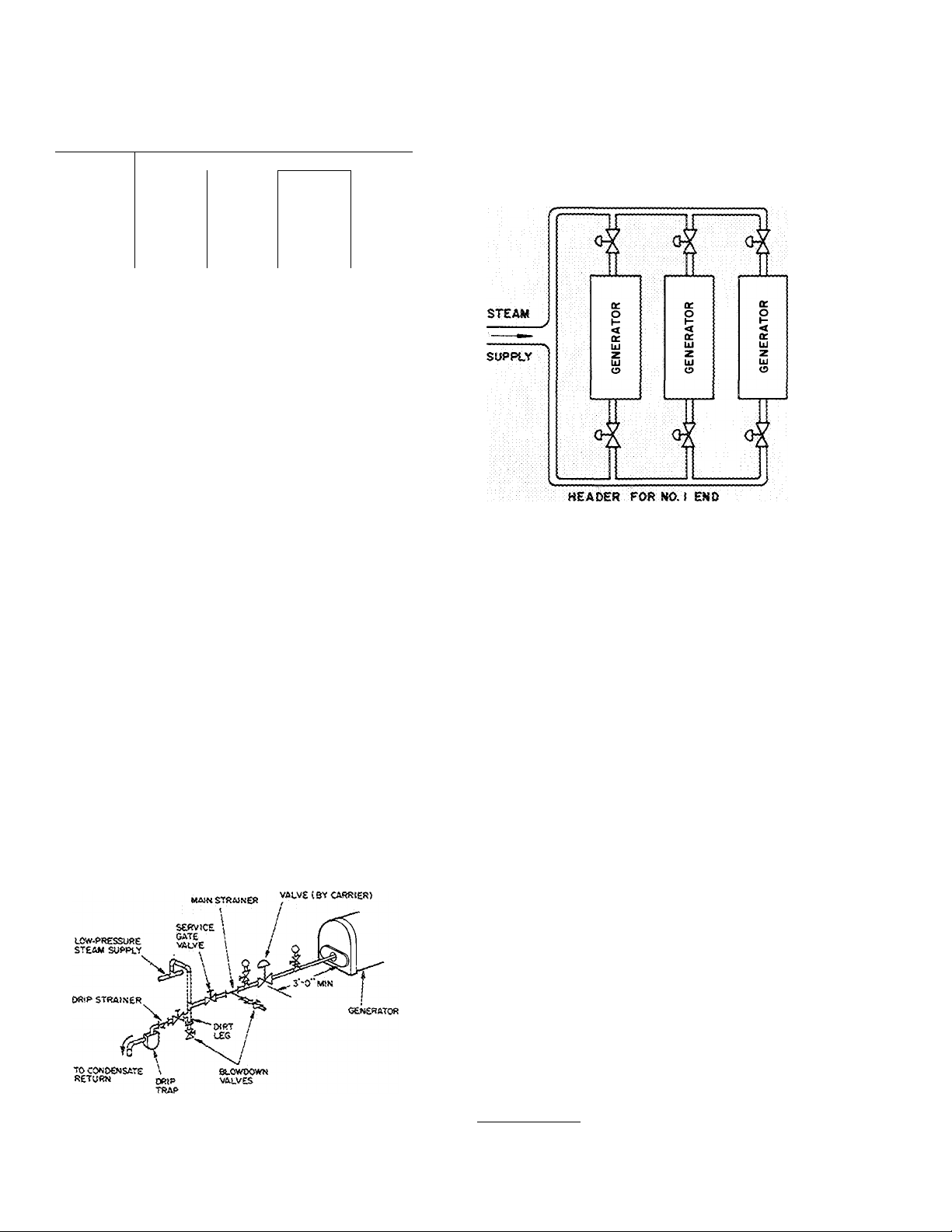
VALVE LOCATION AND PIPING - The steam
control valve should be located a minimum of 3 ft
away from the generator inlet. This is dictated by
good piping practice, to allow equal distribution of
steam in the generator tube bundle. Unequal
distribution of steam in the tube bundle may cause
a loss of capacity. Recommended steam supply
piping for low-pressure steam applications is
illustrated in Fig. 1.
STEAM CONTROt
NOTE; Separate supoiy piping "for each end of machine sizes
16JB077 thro '24,
Fig. 1 — Low-Pressure Steam (2 to 15 psig)
Supply Piping
Machine sizes 16JB077 thru 16JB124 have
steam supply inlets on each end. These are to be
considered as two generators and should be piped
from a common steam header as in multiple
machine installations (see Fig. 2). Each inlet should
then be piped in accordance with Fig. 1.
HEADER FOR N0.2 END
NOTES:
1. Piping appiies to moitipie macbiries connected in paraiief
(3 shown).
2. Each end most be consdered as a separate generator.
3. The feed to each end of each generator should be piped as
shown in rig. 1.
Fig. 2 — Steam Piping For 16JB077 thru 124
Steam piping to the absorption machine should
be designed and supported to allow for thermal
expansion without imposing undue stresses on the
generator inlet. The machine is not designed for,
nor expected to act as, a piping support or anchor
for withstanding thermal stresses.
Condensate Systems — Satisfactory operation of
the absorption machine requires a condensate
handling system designed with the specific characteristics of the absorption machine in mind. The
following is intended to supplement available
reference data on condensate systems such as
Carrier System Design Manual, ASHRAE Guide
and individual manufacturer’s recommendations.
ATMOSPHERIC CONDENSATE RETURN
SYSTEMS (VENTED) - These systems usually
consist of steam traps, vented receiver, condensate
pump, and condensate cooler. Fig. 3 illustrates
typical atmospheric condensate return systems. On
larger machines, with dual steam generators, the
condensate outlet from each generator must be
piped thru separate steam traps.
Trap Selection — Steam traps should be located as
far below the generator outlet as possible. Actual
pressure drop available for trap selection will
depend on exact trap location below the generator
Page 3
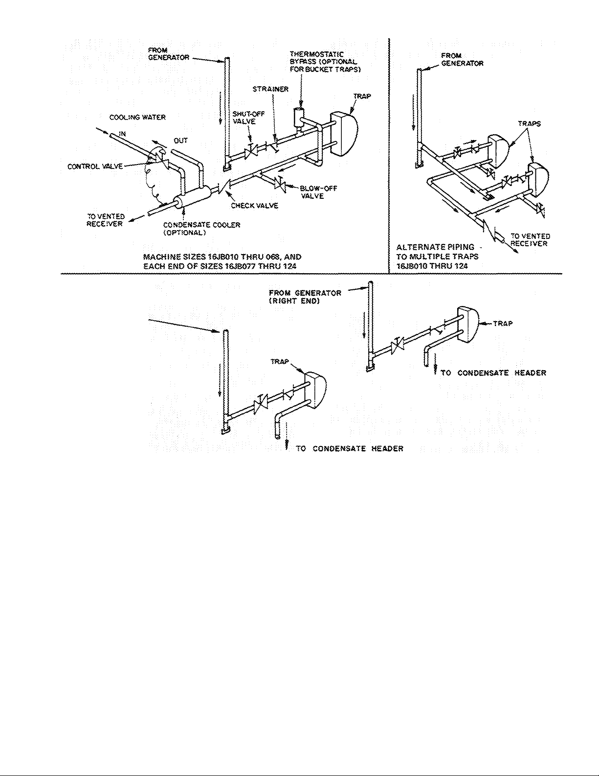
FROM SEMERATOR
(LEFT END)
MACHINE Sizes 16J8077 THRU IZA
Fig. 3 — Typical Atmospheric (Vented) Condensate Return System
outlet, and trap outlet pressure. A vacuum breaker
is factory installed to ensure that operating steam
pressure in the generator does not fall below
atmospheric pressure. Use the following formulas
to determine available trap pressure drop:
Trap pressure drop = trap inlet ~ trap outlet
psig.
Trap inlet pressure = 0 psig + hydrostatic
head to trap inlet -- condensate leg pressure
drop.
Trap design outlet pressure receiver pres
sure + line pressure drop from trap outlet to
receiver.
In determining trap outlet pressure, discount
any liquid head drop to the receiver. This line may
not run full. If there is liquid lift from trap outlet
to the receiver, it must be added to trap outlet
pressure.
Either float-and-thermostat or inverted-bucket
traps may be used, provided the trap is recom
mended by the manufacturer for rapid handhng of
noncondensables. For fast start-up with invertedbucket traps, install an external thermostatic air
vent around the trap.
Traps should be sized for capacity to handle
more condensate than twice the design full-load
steam rate. See steam trap manufacturer’s recom
mendations. Maximum load on the trap will occur
during start-up when generator pressure falls to
atmospheric (0 psig) and steam condenses rapidly.
Page 4

At this time, pressure drop across the steam
control valve is maximum. If boiler capacity is
large enough, the control valve inlet pressure will
stay at design, then flow rate will be limited by
control valve capacity.
Table 1 gives maximum condensate flow for
different inlet steam pressures. Interpolate for
intermediate pressures.
If steam demand on start-up can be held within
a controlled limit, the trap(s) may be sized
accordingly.
When traps are undersized, condensate wiU
back up in the generator with loss in machine
capacity and may cause dangerous water hammer.
Depending on boiler size, the boiler water makeup
system could operate and add water to the boiler.
Sooner or later, excess water would return to the
boiler room and either overflow the hot well to
drain, or if it flows directly into the boiler, it may
shut the boiler down on high boiler water level
control.
Condensate Cooler is used on some atmospheric
condensate systems to reduce or eliminate loss of
flash steam from the open receiver vent. The
condensate cooler must be sized for handling and
condensing flash steam as well as cooHng the
condensate. Condensate is normally cooled to
about 180 F. Pressure drop thru the condensate
cooler should be very low, as it must be added to
trap outlet pressure. If there is a liquid leg down to
the condensate receiver, the condensate cooler and
trap should be located at the bottom of this leg.
When a condensate cooler is used, it is desirable
to use either cold boiler feed water or other cold
water source which can benefit by heat rejected
from hot condensate. Cooling tower bleed water
can be used, but it may be heavy with dissolved
solids and may rapidly foul the cooler. Tower
makeup water can be used when large cooling
towers are part of the system. Extra load to the
tower would be insignificant.
Receiver and Condensate Pumps — When open
receivers are used, the vent should be directed
outside the equipment space to eliminate fogging.
Be careful in using small receivers and closeconnected condensate pumps. Some commercially
available systems may work well on standard
heating systems but can present problems in
handling condensate from absorption machines.
The basic difference in absorption machine oper
ation lies in higher condensate temperatures and
greater amounts of flash vapor. Commercial
heating systems normally deliver condensate to the
receiver thru long return runs. This lowers con
densate temperature to 200 F or lower with
relatively little flash steam.
Absorption machines commonly located close
to the condensate receiver have little or no
condensate cooling. During full load, condensate
may be delivered to the trap at close to 12 psig and
240 F. This creates large amounts of flash steam at
the trap outlet and in the condensate receiver.
Very hot condensate drawn into the condensate
pump may cause cavitation.
To minimize these effects, the following guides
are offered:
1. If equipped with a vented receiver, the inlet line
to the receiver should enter above the receiver
water level. Flash steam can go directly out the
vent without creating turbulence or frothing.
2. Locate the condensate pump as far below
receiver water level as possible to give maxi
mum Net Positive Suction Head (NPSH) to the
pump.
3. If pump suction pipe is located at bottom of
the receiver, use a vortex breaker at the receiver
outlet.
4. Locate pump suction at opposite end of re
ceiver from the condensate inlet. This will
minimize agitation and frothing at pump inlet.
5. A properly selected condensate cooler, as
previously described, will eliminate problems
with flashing.
VACUUM PUMP CONDENSATE RETURN
SYSTEMS are sometimes used to return con
densate from space heating installations. The
vacuum pump maintains the condensate return
system at a subatmospheric pressure and permits
the heating system to operate with subatmospheric
pressure when the heating load is small.
It is generally impractical to use an existing
vacuum pump condensate return system. Con
densate from the absorption machine is far higher
in temperature than condensate from the original
heating system for which the vacuum return pump
■; was selected. Hot condensate forms excessive
quantities of flash vapor when released into the
vacuum return system and will usually cause vapor
lock in either the return piping or the vacuum
return pump, or both. When the existing
condensate return system is a vacuum pump type,
the recommended method of returning condensate
from the machine is a separate wet-return system,
if possible.
As an alternate choice, condensate can be
discharged thru a steam trap to an atmospheric
vent receiver. The receiver discharges flash-cooled
condensate thru a second trap into the vacuum-
return system.
If a condensate cooler is used, condensate may
be cooled to an acceptable level and discharged
Page 5

#
into the vacuum pump condensate return system.
If this method is used, it is desirable to use either
cold boiler feed water or any other cold water
source which will benefit by heat rejected from hot
condensate.
CLOSED CONDENSATE RETURN
SYSTEM
(PRESSURIZED)
16JB010-068 — Many manufacturers have hightemperature condensate units, generally suited for
use with most of the Carrier absorption machine
Une. Because the condensate units are usually quite
high, some of the smaller machines may not be
high enough to provide liquid head for gravity
flow. In these cases, the closed system should not
be used. A typical unit consists of a closed ASME
Code receiver and centrifugal pump for returning
hot condensate to the boiler. This system has the
advantage of complete condensate recovery with
out flash losses often experienced in atmospheric
return systems.
These systems require very careful application
to the absorption machine. There are two common
types of closed condensate systems :
1
CLOSED
CONDENSATE
RECEIVER 1
1 til TO
L-b^-eoa^
CLOSED
CONDENSATE
RECEIVER
TO lA S
NOTE' Each J5IKÌ 5s similar toOf) l&lóOliKSeS machìnes.
Fig. 4 — Closed Condensate Return System
П r~
1
-------------------------------------
(16JB077-124)
HOT WATER MACHINES
The 16JB hot water absorption machines are
furnished with pneumatic controls only. Fig. 5
schematically illustrates the capacity control
valves, controls and control panel. There are two
commonly used piping systems, depending on the
temperature of the supply hot water.
The first type will operate under pressurized
conditions. The pressure between the generator
and receiver is equalized and condensate flows by
gravity to the closed receiver located below the
generator outlet. It is essential that under these
conditions the vacuum breaker on the 16JB
generator should be blocked. This is to prevent air
from building up in the closed receiver. Also, the
closed receiver should be equipped with a device
that is capable of releasing the air that is in the
system after a shutdown period. A thermostatic
vent is usually suppUed for this purpose. In this
type of system, the pumps on the receiver can
pump under vacuum.
The second type of closed system consists of a
closed receiver with atmospheric condensate
pumps. Therefore, the receiver is usually equalized
with the steam chest. In this type of system, the
vacuum breaker and the generator must be left open
so that the receiver cannot go into the vacuum range.
A steam trap is usually recommended.
16JB077-124 — Because the 16JB077-124 units
have two steam inlets, these machines must be
considered as having two generators when applying
a closed condensate system. Each end of the
machine operates at a different steam pressure.
This could cause the condensate to back up into
the generator and cause dangerous water hammer if
the condensate system were not properly designed.
Each end of the machine should be considered
similar to the system on 16JB010-068 units (see
Fig. 4).
077 THRU 124 SIZES ONLY
EPS — Electric-Pneumatic Switch
PE — Pressure-Electric Switch
Fig. 5 — Pneumatic Control Schematic
Piping For Water Temperature of 300 F Or Below
— Fig. 6 gives suggested hot water piping when
supply hot water is 300 F or below. The capacity
of the machine is controlled by regulating the flow
of hot water through the generator. Either a
two-way or three-way capacity control valve (CV)
can be used. Machine sizes 16JB077-124 require
two capacity control valves if partial load effi
ciency of double generators is to be utilized.
Page 6

cw
ASR
ncfTmTSR
<5cJ«3RA70R
PlPtNS rOR MACHINE SiZES 16>® 077 THRO 124,
OR TWO St^íGt£-£^íO MACHINES fN PARAiXEL.
“Acid for 3-way vaive usaae. Pipe MC port (when 3-way valve
useO) to generator irvieris).
Fig. 6 — Suggested Piping For Hot Water Machines
Using Supply Hot Water 300 F or Below
A three-way valve is recommended to ensure a
constant system flow of hot water supply re
gardless of load. A two-way valve is suitable when
throttling of supply hot water at partial load does
not adversely affect the boiler or primary circu
lating pump.
Piping
Fig. 7
For Water Temperature Above 300 F —
gives suggested hot water piping when
supply High-Temperature Hot Water (HTHW) is
above 300 F. The three-way valve — CVl, diverts
HTHW and allows cooler recirculated hot water to
maintain design hot water temperature (300 F
max).
Machine capacity is controlled by regulating the
flow of hot water thru the generator. As machine
load decreases, the chilled water controller senses
the lower chilled water temperature and acts upon
the three-way diverting valve(s) CV2
(CV2 + CV3) to reduce the supply of hot water
to the generator. The recirculating pump, however,
is actually pumping a constant gpm.
The sensor for CVl should be located, if
possible, on the discharge side of the recirculating
pump. The recirculating pump should be sized for
design hot water at a head equal to the pressure
drop through the generator and recirculating loop
piping.
An alarm should be used to warn of excessive
entering hot water temperatures. Excessive tem
peratures could develop if control valve calibration
were lost.
P(PiN<3 FOR MftCHiNE SIZES 077 THRU t24
OR TWO SiNGL£-EN0 MACHINES iNRARALLEL
Fig. 7 — Suggested Piping For Hot Water Machines
Using Supply Hot Water Above 300 F
RECIRCULATING WATER CALCULATIONS Assume for example purposes;
Available supply hot water temp = 400 F
Design quantity of hot water needed = 243 gpm
Design entering hot water temp = 300 F
Design leaving hot water temp = 229 F
1. Determine the design hot water temperature
drop (ATi) thru the machine.
AT 1 = ent hot water (F) — Ivg hot water (F)
- 300 F - 229 F
= 71 F
2. Determine the temperature drop of 400 F
water (AT2) thru the machine.
AT2 = supply hot water (F) — Ivg hot water (F)
- 400 F^ 229 F
= 171 F
3. Determine the amount (gpm) of 400 F water
required.
Gpm of 400 F water
gpm of 300 F water
ATI
AT2
243 X-
71
171
= 101 gpm
Determine the amount (gpm) of recirculated
229 F water required to meet design quantity
of water needed:
Gpm of 229 F water - gpm of 300 F water
— gpm of 400 F water
= 243 - 101
- 142 gpm
Page 7

VALVE SIZING — The hot water capacity control
valve CV2, should be sized to handle full design
flow on machine sizes 010-068. Valves CV2 and
CVS on machine sizes 077-124 are each sized at
one-half design flow. The pressure drop and sizing
formula used in sizing the valve(s) should be
consistent with valve manufacturer’s recommenda
tions. The three-way diverting valve should be sized
to handle the design supply of high-temperature
hot water (HTHW) and must be suitable for high
temperature duty.
Methods Other Than Recirculation to lower supply
hot water temperature to acceptable levels (300 F
max) are:
1. A water-to-water heat exchanger
2. A hot water-to-steam converter
Rupture Disc — All 16JB hot water machines are
provided with a rupture disc on the generator shell
for safety reasons. A generator tube failure could
subject the shell to hot water supply working
pressure.
RELIEF PIPING — Some apphcations have relief
piping installed from the rupture disc discharge to
a location where high-temperature steam and
lithium bromide will not cause damage or injury.
Relief piping must include access to the rupture
disc, allowing replacement in case of failure. Piping
must be supported independent of the machine.
Hot Water Inlet Pressure — It is necessary to ensure
that generator hot water pressure is higher than
saturation pressure corresponding to the inlet hot
water temperature.
Minimum pressures are approximately equal to
10 psi plus the saturation pressure corresponding
to inlet water temperature. Using a recommended
minimum pressure will ensure that hot water inlet
pressure drops will not cause the pressure in the
lines to drop below saturation pressure. This could
cause flashing and water hammer.
3. Winter Operation — If the absorption machine
is to be applied under winter operating
conditions, an indoor cooling tower sump
should be provided to protect the cooling tower
water from freezing.
GENERAL INFORMATION
Insulation — Machine cold surfaces, subject to
sweating and corrosion, are factory insulated.
Refer to Fig. 8 and Table 2 for details.
d> 6 é
¡S3 FACTORY INSULATION
LEGEND
1 — Refrigeract Pump Housing
2 — EvaporaTor Shell
3 — Refrigerant Suction Piping
Fig. 8 — Machine Cold Surfaces
CONDENSING WATER TEMP CONTROL
If the absorption machine is to be applied
under conditions where the condensing water
temperature can fall below 55 F, condensing water
temperature control is required. This can be
accomplished by:
1. Fan Cycling — On a single-cell coohng tower,
the tower fan can be shut off when the
temperature of the water reaches 55 F. This
allows the temperature of the tower water to
warm up using the heat rejected from the
machine. In order to ensure against rapid fan
cycling, which can cause fan motor problems, it
is recommended that the cooling tower water
temperature be allowed to rise to design
temperature before fan operation is resumed.
2. Multiple-Cell Tower — The temperature of a
multiple-cell tower can be controlled by
shutting off the number of operating cells. This
creates an effect similar to shutting the fan off
in a single-cell tower. The controls should be
adjusted to shut off in stages to 55 F and come
on again in predetermined stages.
Table 2 — Insulation For Cold Surfaces
EVAP
UNIT
SHELL
16JB
TTlff“
012
014
018
021
024
028
032
036
041
047
“054~
057
061
068
w
084
097
107
115
124
^Quantity of insulation specified is adequate to cover cooler water
boxes and covers on both ends of machine
REFRIG
PUMP(S)
(ft2)
75 3 6 10 ft
96 3 6 11 ft 12
114
147
177
188
216
275 8 16
328
360 8
(ft 2)
REFRIG
Suction
(ft2)
3 6 12 ft 15
3
4 6 12 ft
4 9 15 ft 21
4 10
8 17 60 ft
LINES
2 in.
Disch
6 12 ft 17
13 ft
48 ft 21
19
60 ft
COOLER
WATER BOXES
AND COVERS*
(ft2)
9
20
24
24
27
Page 8

The generator shell and some of the machine
piping will become hot during operation. If insula
tion is to be used as a safety precaution, or to
reduce ambient temperature in the machine room,
we recommend insulating the surfaces shown in
Fig. 9. Hot-surface dimensions are given in Table 3.
Generator insulation can be either blanket-type
or low-pressure boiler insulation. Insulation used
for piping is generally standard low-pressure steam
pipe insulation.
Table 3 — Insulation For Hot Surfaces*
GENt
UNIT
SHELL
16JB
010
012
014
018
021
024
028
032
036
041
047
054
057
061
068
077
084
097
107
115
124
•Refer to Fig. 10 for location of hot surfaces.
fl nciudes outiet box and ends
EXCH
(ft 2)
(ft 2)
62
67 45
72
77 55
82
98
98 60
152
184 no 18 4
184
GEN —Generator
HT EXCH — Heat Exchanger
STRONG
HT
SOL LINE
Lgth
Size
(in.)
(ft)
40 7 3 20
7 3 21 2 12
50 8
60
55 8 4
102
1 18
4 22
9 4
10 4
10 4
16 4 44 2 3 4
20 4 49
WEAK
SOL LINE
Lgth
Size
(in.)
(ft)
V/2
2
23
2'/2
24
3 16 4
22 3 10 4
24 3
3
47
3
GEN
OVERFLOW
(GO) TUBE
Lgth
(ft)
1 1
13 4
15 4
12
4
4
Size
(in.)
3
4
4
4
4
HOT SURFACES THAT
CAN BE INSULATED
LEGEND
1 — Generator Shell (refer to Table 4 for sq ft surface area)
2 — Steam Supply Line
3 — Condensate Line
4 — Weak Solution Line (to generator)
5 — Strong Solution Line (from generator)
6 — Generator Overfiow Tube (only hot during abnormal
conditions)
7 — Heat Exchanger
Fig. 9 — Machine Hot Surfaces
isolation — 16JB machines are not in themselves a
major source of vibration ; and isolation equipment
is not supplied with the machine unless requested
on the order. It is possible, however, for a machine
to receive and transmit vibrations from
other
sources that are imperfectly isolated such as
condensing water pumps, chilled water pumps, or
other piping. Isolation packages are available from
a number of manufacturers. Specifications for
Carrier machines are given in Table 4.
Table 4 — Isolation Pad and Soleplate
Specifications
UNIT
16JB
010
012
014
018
021
024
028
032
036
041
047
054
057
061
068
077
084
097
107
115
124
NOTE:
Higher isolation efficiencies may be obtained with double-layer
pads. Double-layer pads, factory-fused together, are available from
various manufacturers. If two single-layer pads are used, a metal
divider equal to pad dimensions should be inserted between iayers.
NO. (EACH)
OF PADS AND
SOLEPLATES
4 9 X 6 X %
4 9 X 10 X %
4
4
4
4
4
6
6
6
PAD
DIMENSIONS
(in.)
9 X 12 X Vs
9 X 14 X %
9 X 18 X %
12 X 18 X Vs
14 X 18 X %
12 X 18 X %
15 X 18 X Vs
16 X 18 X % 17 X 19 X
SOLEPLATE
DIMENSIONS
(in.)
10 X 7 X V2
10 X 11 X V2
10
X 13 X %
10 X 1 5 X
10 X 19 X %
13 X 19 X %
15 X 19 X h
13 X 19 X %
16 X 19 X %
(4
‘/ 2
Page 9

The integral shipping skids, or base rails, are
normally left on the machine. However, the base
rails may be removed, if desired, but not until the
machine is in final position. When isolation pads
are used, they should be located under the corners
of the machine, atop soleplates with 1/2-in. min
imum thickness (see Fig. 10). The soleplate ensures
machine contact on the floor only at the corners
when base rails are left on. Shims may be inserted
under the soleplates for leveling the machine.
Grouting is optional.
Outdoor Installation — Outdoor installation of the
16JB absorption machine creates a number of
special problems which must be resolved. Such
applications should be considered only when the
customer has qualified operating personnel,
familiar with the maintenance of mechanical equip
ment located outdoors. Standard machines require
protection from weather. A simple, heated
structure is preferred. If this is not possible,
protection from the weather must be provided by
machine modifications.
WEATHERPROOFING -- Pneumatic control sys
tems are recommended for outdoor installations.
Controls can be factory furnished to meet NEMA
No. 4 Waterproofing Specifications.
FREEZE PROTECTION — When the machine area
may be subjected to temperatures below 40 F and
if the machine is to be shut down for an extended
time during these low-temperature periods, all
water circuits and tube bundles should be drained,
then filled with ethylene glycol. Table 5 lists
storage volumes of 16JB header and tube bundles.
This data can be used when calculating the
quantity of ethylene glycol needed to provide
adequate freeze protection.
Fig. 10 — Typical isolation Assembly
Explosionproof Machines — 16JB standard absorp
tion machines can be factory equipped with
explosionproof electric motors and controls
suitable for Class 1, Group D hazardous locations
specified by the National Electrical Code. Modi
fications to the standard control system are
described in the controls application publications.
Table 5 Header and Tube Bundle Storage
Volumes (gal.)
UNIT
EVAPORATOR ABSORBER CONDENSER
16JB
010
012
014
018
021
024
028
032
036
041
047
054
057
061
068
077 ^
084
097
107
115
124
GEN — Generator
106
108
129 179 68
158
198 271
228
25 27
28
30 35 17 17
43 46
48 51
57
64 69
76
83
96
30 16 16
62
83
90
104
117 59
150 57 74
215 129
310 186 150
14
24
26
32
36
42
46 43
52 49
163 138
HOT
WATER
GEN
14
23
25
30
34
39
56
87
106
Page 10

Tube Removal — Clearance for tube removal
should be considered when planning a piping
system. The 16JB machines are designed so all
tubes are accessible for cleaning or servicing should
the need arise. Refer to Fig. 11 for tube pulling
clearance dimensions and data. Evaporator,
absorber and condenser tubes may be pulled from
either end.
UNIT
16J8
010,0i2.0U
0t8,02t
024,028
032,036
041,047
i 16-lOli
i
1 17- Oii
i 16-U’4
£’.7- 2\
054,057 r 6- 3%
061,068
i 21- Sy, ; 7- 3ii
077,084 i 32- 2 i 6- 314
097,107
} 32- 2
115,124 ; 2 /—SO /<
'Weights given are for each cover.
NOTE: Minimym space for tube removai !Din>er;sion O) may be tocated on either end.
CLEARANCE DIMENSIONS (ft
A 8 c
: 3-
7- sy. ; 14-2
\ 4- 4Vi 7- 914
; 5- Oti
i 6- 3
s 6- n
8- 9y ' 14-2
10- H4 ; 14-2
;i- 6‘/*
■•-10
13- 214
1:- 4
> 7— 1 ^
12-tOy
13- 9y
Certified dimension drawings are available on request.
Fig. 11 — Tube Pulling Clearance Data
— in.)
i D
E
4- S
; 14-2
.5- 1
5-10 ; 4- 0 < 88
6-10 ; 5- 0
: 14-2 8- 6 ; 5- 3
i 19-3
: 19-3
: 29-1
8- 7 i 5- 0
9- 3
8- .5
i 29-1 9" 5 j 6— 6 193
• 29—^ 9- 9
COVER PLATE WEIGHTS* (lb)
F
; 2- 8
i 3- 6
Comlertser(G)
45
50
; Absorber(H) Evaporator{J)
: 100 ;
177 ; 177
275 ; 275
87
t
>
>
!07
169 i 318 ;
; 5-11 ¡69
; 325 :
i 460 ;
; 389 i
i 5— 0 153 1 310 i
“T ssT" r
I 6- G
•93
1 438 t
'•■DO
32.5
460
384
471
384
471
566
10
Page 11

Manufacturer reserves the right to change any product specifications without notice.
CARRIER AIR CONDITIONING COMPANY • SYRACUSE, NEW YORK
Tab 15
Form 16JB-2XA New
Printed in U.S.A. 6-71 Codes MA and ML Catalog No. 511-602
 Loading...