

Page 1

ti
Hermetic Absorption Liquid Chillers
Carrier
MACHINE OPERATION
MACHINE START-STOP SYSTEMS
General - The exact start-stop system for a given
machine is established by the customer. Systems
can vary from one installation to another. These
systems and procedures are meant for general
guidelines only.
The three most common types of systems are
given below. Review these systems and decide
which applies to your machine. Then follow the
start-stop procedure given.
NOTE: If machine has been shut down for more
than 2 days, follow procedures under Start-Up
After Limited Shutdown or Start-Up After
Extended Shutdown. In all cases below, when
machine starts, the white run light will en
ergize. When the machine stops, the light will
go out after automatic dilution.
Automatic Start-Stop System - Starting and stop
ping with this system is accomplished by an
automatic controller such as a thermostat or
time clock, etc. Also, an AUTO-MANUAL switch
is provided so the machine can be started bypressing machine START button with switch in
MANUAL position. All auxiliary equipment is
tied in with the machine control circuit and will
start when the machine starts. If automatic time
delay relays are provided, the machine will start
after a preselected time interval.
The operating engineer must make periodic
checks to ensure that the machine with auxiliary
equipment is operating satisfactorily.
PROCEDURES
1. Place AUTO-MANUAL switch in the AUTOpo-
sition for the machine to start or stop automat
ically. The automatic controller determines
when the machine starts or stops.
2. To start fully automatic machines after limited
or extended shutdown place the AUTO-MANUAL
switch in MANUAL and press the START
button. Then follow start-up procedures for
limited or extended shutdown. Only after man
ual start has been completed should the AUTO
MANUAL switch be placed in AUTO.
NOTE: When the machine shuts down either
automatically or manually, the refrigerant
and solution pumps will continue to run
until automatic dilution is completed.
Semiautomatic Start-Stop System - All auxiliary
equipment used with this system is tied directly
to the control circuit. It is necessary for the
operating engineer to press the START button
to start the condensing water pump, chilled water
pump, machine pumps, and cooling tower fan
(if used).
PROCEDURES
1. Press STOP button to stop machine.
START button to start machine.
NOTE: On shutdown the machine pumps will
continue to run until automatic dilution
is completed.
Semiautomatic Start-Stop System with Manual
Auxiliaries - All auxiliaries must be started
manually.
PROCEDURES
1. Start chilled water pump.
2. Start condensing water pump.
3. Start cooling tower fan (if used). (This depends
on outside temperature.)
4. Press START button to start machine.
5. To stop machine, press STOP button. Then
stop the following:
a. Cooling tower fan (if used).
b. Condenser water pump.
c. Chilled water pump.
NOTE: The refrigerant and solution
pumps will continue to run until auto
matic dilution is completed.
MACHINE START-UP PROCEDURES
General - Procedures for start-up differ depend
ing on how long the machine has been shut down.
There are two start-up procedures: Start-up
after limited shutdown (3 days to 3 weeks), and
start-up after extended shutdown (over 3 weeks).
Start-Up After Limited Shutdown
PROCEDURES
1. Start the machine as outlined for your system
under Machine Start-Stop Systems.
2. Check the leaving chilled water temperature.
If temperature drops to design, then steps 3
and 4 are not necessary. If the temperature
does not drop to design, noncondensables are
probably present in the machine. Proceed
with steps 3 and 4.
3. Determine the amount of noncondensables by
taking an absorber loss reading (the temper
ature difference between the refrigerant and
solution vapor). To determine absorber loss,
refer to Carrier Standard Service Techniques,
publication SM-16. A machine with absorber
loss of less than 6 F can normally be started
without the machine solution becoming solid
ified. If absorber loss is greater than 6 F,
auxiliary evacuation is recommended. A ma
chine fully evacuated will normally have an
absorber loss of 2 F or less. Instructions
for auxiliary evacuation are in Carrier Stand
ard Service Techniques, publication SM-16.
Press
Carrier Corporation 1968 Printed in U.S.A.
1-68
16JA-1SO
Page 2

To prevent solidification while purging:
a. Place reclaim switch to MANUAL.
b. Throttle back steam control valve.
(1) Electronic Control - Turn the control
point adjustor up approximately ten
degrees (ten divisions).
(2) Pneumatic Control - Turn the chilled
water thermostat set point up ten
degrees.
4. Evaluate machine tightness with a noncon
densable accumulation rate check. Refer to
Carrier Standard Service Techniques, publica
tion SM-16.
Start-Up After Extended Shutdown - This pro
cedure is critical since accumulated noncon
densables may allow the machine solution to
solidify if the following precautions are not taken,
PROCEDURES
1. Start the machine as outlined for your system
under Machine Start-Up Procedures. Make
sure steam valve is closed. If absorber solu
tion level is high (above 9 in.) and refrigerant
pump is noisy, open steam valve until absorber
level indicator shows approximately 9 in. of
solution, then close steam valve. Place refrig
erant pump switch in ON position.
2. Determine absorber loss by following proce
dures outlined in Carrier Standard Service
Techniques, publication SM-16.
a. If absorber loss is less than 6 F, open
steam valve and allow machine to go into
automatic operation.
b. If absorber loss is 6 F or greater, auxil
iary evacuation is required. Use instruc
tions for auxiliary evacuation provided in
Carrier Standard Service Techniques, pub
lication SM-16.
3. Continue auxiliary evacuation until absorber
loss is less than 6 F. Place machine in auto
matic operation.
4. After auxiliary evacuation, evaluate machine
tightness with a noncondensable accumulation
rate check.
WINTER CONDITIONS
General - At the end of each cooling season when
the machine is no longer required use one of the
following winter shutdown procedures. The choice
depends on whether the machine ambient tempera
ture will be kept above or below freezing.
Shutdown Procedures
BELOW FREEZING
1. Stop machine and wait until automatic dilution
completes and machine pumps stop.
2. Set dilution thermostat to its lowest possible
setting.
3. Connect a hose between solution and refrig
erant pump service valves. Open both valves.
4. Switch refrigerant pump ON-OFF switch to
OFF and solution pump switch to ON.
5. Press START button and allow solution pump
to run for approximately 5 minutes.
NOTE: This procedure contaminates the
refrigerant with lithium bromide solution
lowering the refrigerant freezing point.
6. Press STOP button and reset dilution thermo
stat to 140 F (refer to Checking Dilution Ther
mostat under Maintenance).
7. Drain water from all chilled water, condensing,
steam and condensate circuits. Flush all cir
cuits with ethylene glycol.
ABOVE FREEZING
1. Press STOP button.
2. Allow machine to go thru automatic dilution.
When dilution has completed, machine may
be left in this condition until spring start-up.
Start-Up Procedures
BELOW FREEZING
1. Refill all water circuits that were drained at
shutdown.
2. Follow Start-Up After Extended Shutdown pro
cedures.
3. Reclaim lithium bromide from refrigerant
circuit. Follow Reclaim Solution procedures
given under Maintenance.
4. Restart machine.
ABOVE FREEZING
1. If machine vacuum was broken for maintenance
work, etc., follow auxiliary evacuation pro
cedures outlined in Carrier Standard Service
Techniques, publication SM-16. Then follow
Start-Up After Extended Shutdown procedures.
2. If machine vacuum was not broken, follow
Start-Up After Extended Shutdown procedures.
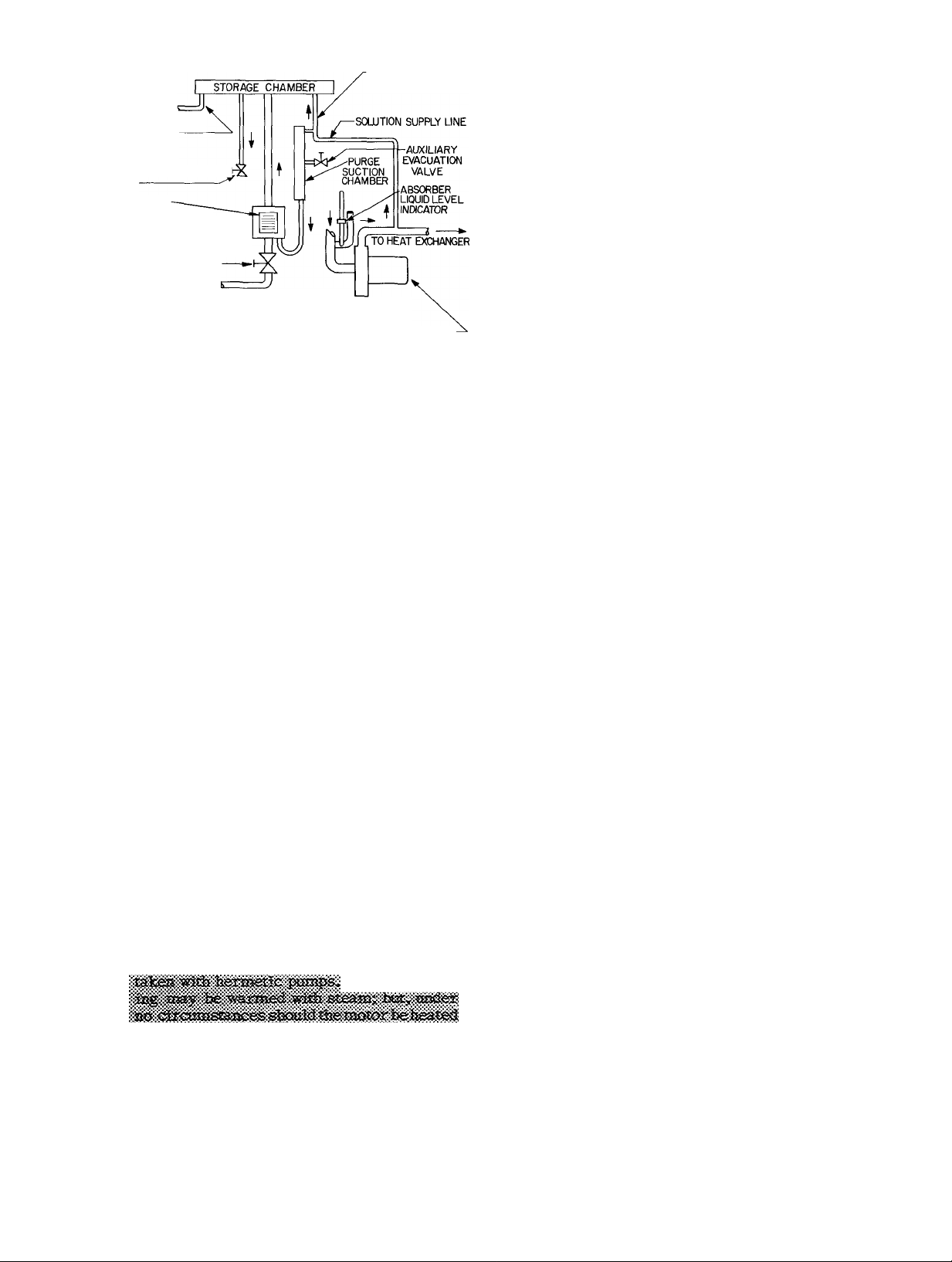
PURGE OPERATION
General - The 16JA purge unit automatically per
forms the following functions:
1. Removes noncondensables from the machine.
2. Accumulates these noncondensables in the
purge storage chamber where they will not
affect the machine performance.
3. Provides an indication of the degree of air
leakage into the machine.
The 16JA purge unit cannot be used as an auxil
iary evacuation device to evacuate the machine.
When the purge exhaust light (red) is energized
during machine operation, it indicates that the
purge must be manually exhausted. For instruc
tions refer to the instruction sticker located on the
separation chamber (Fig. 1) or use the following
procedure.
Page 3
CONDENSER PURGE
SUCTION LINE
PURGE EXHAUST
VALVE
INSTRUCTION
STICKER PURGE
PURGE RETURN VALVE
TO GENERATOR OVERFLOW TUBE
SEPARATION
CHAMBER
STORAGE CHAMBER
SUPPLY LINE
service valve. With correct pump rotation, the
gage will indicate a positive reading above at
mospheric pressure. If the pump is solidified,
the gage will indicate atmospheric pressure.
If the casing is partially desolidified and the
pump will not turn, the pressure gage will in
dicate a deep vacuum. Continue to heat the
casing until the pump is desolidified. Desolid
ification of the heat exchanger will take place
automatically once the pump starts functioning.
3. Refer to Troubleshooting Guide for possible
causes of solidification and their correction.
SOLUTION PUMP-
Fig. 1 - Purge Exhaust System
Manual Exhaust Procedures
1. Close purge return valve.
2. Wait 10 minutes for storage chamber to
pressurize.
3. Slowly open purge exhaust valve. If level in
container drops, shut valve and wait 2 minutes.
Reopen valve. If bubbles appear, keep valve
open until bubbles stop and level in container
rises, then close valve.
4. Collect lithium bromide solution to recharge
into machine. Recharging procedures are given
in Carrier Standard Service Techniques, pub
lication SM-16.
SOLUTION DESOLIDIFICATION
General - Should solidification occur, it will occur
usually in the shell side ofthe heat exchanger, pre
venting the strong solution in the generator from
returning to the absorber thru the strong solution
line. However, the strong solution will be returned
to the absorber thru the generator overflow tube
(Fig. 6) thereby desolidifying automatically.
If during a shutdown period solidification has
occurred to the extent that the solution pump will
not rotate and the motor overloads trip put, desolidify by using the following procedure.
PROCEDURE
1. Heat the pump casing and adjacent lines with
steam until the pump will rotate. Be careful
not to allow steam and condensate to enter the
pump motor and controls.
jpr«ic3iCitK»3S miSt he
fi a beaîiïig torch 1& used, cadesr
lîcf hhaajà heat he
iÈC35eciÎ3f to âîiy ifeïige <M№iectiOîias3â!e’S'«ry
2. Confirm pump rotation. Rotation of the her
metic pump cannot be viewed directly. Install
a compound pressure gage on the solution pump
MAINTENANCE
INTRODUCTION
General - The following are routine steps nec
essary for normal preventive maintenance on
16JA Hermetic Absorption Liquid Chillers.
To ensure the continued satisfactory perform
ance of the machine, these schedules must be
closely adhered to.
We recommend the suggested steps be per
formed as often as indicated, and that an accurate
log be kept to aid in diagnosing any troubles.
Certain components and operations should be
checked on an individual basis as needed.
EACH MONTH
Reclaim Solution - During normal operation it is
possible that some lithium bromide might carry
over into the refrigerant circuit.
To determine if contamination exists, remove
a refrigerant sample from the machine using
refrigerant and solution sampling procedures out
lined in Carrier Standard Service Techniques,
publication SM-16. Measure the specific gravity
of the sample. If the value exceeds 1,02, the solu
tion must be reclaimed.
RECLAIM PROCEDURE FOR CONTINUOUS OP
ERATION
1. Place reclaim valve switch in MANUAL posi
tion. Wait for approximately 15 minutes. This
causes refrigerant to flow into the solution
circuit where the lithium bromide solution
is reclaimed.
2, Place reclaim switch in AUTO position, de
energizing the refrigerant solenoid valve,
thus stopping refrigerant flow.
RECLAIM PROCEDURE FOR FREQUENT SHUT
DOWN - When the machine is shut down, the re
claim valve will automatically reclaim the lithium
bromide salt solution.
NOTE: If the reclaim solenoid valve does not
energize during the reclaim procedure (aud
ible click, and typical rattling noise of refrig
erant passing thru the valve) contact your
nearest Carrier representative for assistance.
Page 4

Check Machine Tightness - The most important
maintenance item on the absorption machine is
maintaining vacuum tightness within acceptable
limits. Check machine tightness by determining
the noncondensable accumulation rate. Use pro
cedures given in Carrier Standard Service Tech
niques, publication SM-16.
condenser water temperature. Turn down control
point adjuster below design leaving chilled water
temperature setting. Repeat steps 1 thru 4.
Continual removal of water indicates leakage in
one of the tube bundles. Leak test by using proce
dures outlined in Carrier Standard Service Tech
niques, publication SM-16.
EVERY 2 MONTHS
Check Dilution Thermostat - The dilution thermo
stat should be open when the strong solution drops
to 140 F. If temperature cutout point is not 140 F,
insert screwdriver in slot on face of thermostat
(located on strong solution line) and turn adjust
ment dial until cutout occurs at 140 F.
Check Low-Temperature Cutout - Remove low-
temperature cutout sensing element from sep
arable well in the evaporator shell. Place it in
an ice bath. Low-temperature cutout should trip
at 5 F below design leaving chilled water tem
perature or a minimum of 36 F. The actual cutout
point is the dial setting less 3 F differential. When
the control trips, the machine will shut down
immediately without going thru a dilution cycle.
NOTE: The chilled water pump will continue
to run if hooked up in the standard wiring
arrangement.
EVERY 6 MONTHS
Check Evaporator Water Charge-Check the evap
orator water charge to determine if the reclaim
valve has energized. If valve has energized then
either tube leakage or excess refrigerant is
indicated.
Reclaim should start at full load (corresponds
to approximately 62 percent lithium bromide in
absorber for standard nominal conditions). Check
as follows:
1. Operate machine at full load with design en
tering condensing water and design leaving
chilled water.
2. Remove a sample of evaporator water from
refrigerant pump service valve and check the
specific gravity. If specific gravity is below
1.02 proceed with step 3. If specific gravity
is above 1.02 reclaim solution (see instruc
tions for Reclaim Solution, page 3) until specific
gravity is below this point, then proceed with
step 3.
3. Evaluate absorber loss. Should be 2 F or less.
If more, purge air from machine.
4. Check reclaim line by feel. Listen for refrig
erant flow (audible). If reclaim line is already
cold, with audible refrigerant flow, remove
refrigerant until reclaim valve closes (audible
click) and refrigerant flow ceases.
If machine is operating under light load, it will
be necessary to concentrate the absorber weak
solution to 62 percent. To do this, raise entering
Check Capacity Control Valve - Check to see if
leaving chilled water is being maintained at design
temperature. If not, adjust the electronic or
pneumatic control.
TO ADJUST ELECTRONIC CONTROL
1. Move control point adjuster clockwise to in
crease temperature, or counterclockwise to
decrease temperature. If this fails to bring
leaving chilled water within design temper
ature, perform step 2.
2. Replace vacuum tubes in control motor. Make
sure that new tubes are installed in correct
plugs. If this fails to bring leaving chilled
water within design temperature, proceed
with step 3,
3. Clean relay contacts with stiff paper. If this
fails to correct problem, contact Carrier
immediately.
TO ADJUST PNEUMATIC CONTROL
1. Reset control point setting to design.
2. If above fails to correct problem, contact
Carrier immediately.
Check Cooling Tower Bypass Control - If control
is not maintaining design entering condensing
water temperature, recalibrate the control ther
mostat. For information, contact the valve (or
control) manufacturer.
EVERY YEAR
Check for Absorber and Condenser Scale - Check
absorber and condenser tubes to see if cleaning
is required. Soft scale may be removed with tube
cleaning brushes. When hard scale has formed,
it may be necessary to chemically clean the tubes.
If a scale problem occurs, contact a water treat
ment representative. Annual tube cleaning may
not be required if adequate water treatment is
maintained.
Recharge Lithiunn Bromide - Recharge lithium
bromide when the purge exhaust bottle becomes
filled.
PROCEDURES
1. Open the exhaust valve and allow solution to
be forced back into the purge,
2. Close the exhaust valve when the level nears
the end of the tube. Do not allow air to be
drawn into the tube.
Page 5

EVERY 2 YEARS
Replace Service Valve Diaphragms - Require
ment to replace valve diaphragms is determined
by valve usage or number of machine operating
hours. Less frequent usage of valves and lower
number of machine operating hours results in
longer life span for valve diaphragms. With min
imum usage the requirement to replace dia
phragms might be 3 years. With maximum usage
they will need to be replaced in approximately
2 years.
PROCEDURES
1. Remove all solution and refrigerant from the
machine.
2. Break vacuum with nitrogen unless performed
previously. Refer to Carrier Standard Service
Techniques, publication SM-16,
3. Remove solution and refrigerant from machine
unless performed previously.
NOTE: Store solution in clean containers
for recharging.
4. Remove old valve diaphragms.
5. Install new valve diaphragms. Torque bolts
to 3 ft lb.
6. Leak test all affected joints to make sure
that all valves are leak tight.
7. Replace solution and refrigerant in machine.
NOTE: The same quantity of solution and
refrigerant removed from the machine must
be charged back into the machine.
3, Pull stator and adapter flange straight back
from pump casing. If paint has frozen flange
to casing, gently pry between adapter flange
and pump discharge pipe (item 4) until paint
seal is broken.
4, Remove and discard gasket (item 5),
5. Remove impeller (item 6) by straightening
locking tabs on impeller lock washer (item 7).
Prevent impeller from rotating while removing
locking bolt (item 8). Remove impeller key in
the shaft.
6. Remove bearing and wearing ring housing:
a. F-8 Frame Pumps (Fig. 2) - Unbolt cap
screws (item 9). Remove bearing and wear
ing ring housing (item 10).
OAiliiWi Do. safe afc bearii® to
or 0300 XEOOr. AiSO oo ca. _
fel ucc lo Jos£i retaimfag clip iitom 18>
b. F-66 Frame Pumps (Fig. 3) - Remove stud
nuts (item 9). Use jacking screws to loosen
bearing and wearing ring housing (item 10),
Insert jacking screws in tapped holes pro
vided in wearing ring housing.
7, Slide out rotor (item 11) carefully, so as not
to damage the stator can (item 12), rotor can
(item 13), or motor end bearing (item 14).
8. Remove motor end bearing, retaining clip (item
15) and spring (item 16). Remove spring bear
ing plate (item 17) used on Frame F-8 only.
8. Re-evacuate the machine after service work
is completed. See auxiliary evacuation pro
cedures in Carrier Standard Service Tech
niques, publication SM-16.
EVERY 5 YEARS
Inspect Hermetic Pumps - Pumps used on Carrier
Absorption Machines are hermetic and do not re
quire seals. Pump motors are cooled by the fluid
being pumped and are thermally protected with
high-temperature cutouts (Klixons).
Inspect hermetic pumps and motors every
5 years or 20,000 hours, whichever comes first,
DISASSEMBLY PROCEDURES - Refer to Fig, 2
and Fig. 3.
1. Disconnect motor power leads at junction box
on stator. Mark leads for ease in reassembly.
2, Remove bolts (item 1) holding motor adapter
flange (item 2) to pump casing (item 3),
NOTE: Use blocking to support weight of
motor stator when removing bolts.
INSPECTION PROCEDURES
1. Check for bearing wear by measuring depth
from large end to start of cone (Fig. 4). If
wear exceeds 3/16 in,, replace the bearing.
Use standard parts lists for ordering new
bearing.
Instructions for bearing replacement are fur
nished with new bearing.
2. Check recirculation passages (item 20). Clean
as required.
3. Check impeller stator can, rotor can and
wearing rings for wear. Clean or replace
if necessary.
NOTE: If wearing rings require replace
ment, break the old ring with a chisel.
These rings were staked in place. Do not
restake new wearing ring.
4. Check spring loaded bearings for free move
ment within the bearing housing.
Page 6

note: item numbers are referenced in
DISASSEMBLY AND REASSEMBLY
PROCEDURES.
Fig. 2 - F-8 Frame Pumps
NOTE: ITEM NUMBERS ARE REFERENCED IN
DISASSEMBLY AND REASSEMBLY
PROCEDURES
Fig. 3 - F-66 Frame Pumps
Page 7

J."
MAX
16
REASSEMBLY PROCEDURES
Refer to Fig. 2
and 3.
1. Clean all parts.
2. Replace wearing rings. Use hand pressure
to position new rings.
3. Insert motor end spring and bearing plate
(F-8 Frame Pump only).
4. Install retaining clip and spring in bear
ing housing.
5. Insert motor end bearing into housing. Should
be a free sliding fit without excessive ra
dial play.
6. Guide the rotor into position.
7. Install end bearing in bearing and wearing
ring housing:
a. Frame F-8 Pumps - Be sure bearing re
tainer pin is in the retainer slot.
b. Frame F-66 Pumps - Be sure bearing re
tainer pin is in the bearing retainer hole.
8. Install bearing and wearing ring housing.
Tighten cap screws (Frame F-8 pumps), or
stud nuts (Frame F-66 pumps).
9. Install impeller with impeller key, lock
washer and locking bolt. Bend tabs of washers
over flats of locking bolt heads.
10. Install new 1/32 in. thick EPR gasket by
removing transfer tape from adhesive side
of gasket and positioning gasket on adapter
flange periphery.
11. Assemble motor stator housing and adapter
flange assembly by sliding the housing and
adapter flange assembly into pump casing.
Refer to step 2 of Disassembly Procedures
as to blocking. Install and tighten bolts and
washers. Remove blocking.
12. Connect power supply to stator junction box.
AS NEEDED
Adding Octyl Alcohol - Octyl alcohol is usually
required when the leaving chilled water tempera
ture starts to rise above design providing the
control set point has not been altered. Since a
rise in leaving chilled water temperature is also
an indication of fouled condensing water tubes,
use the following procedure to determine if
alcohol is required.
PROCEDURE
1. Remove a sample of solution from solution
pump service valve. If solution has no odor
of alcohol (very pungent), then octyl alcohol
should be added.
2. Add alcohol using the procedure outlined in
Carrier Standard Service Techniques, pub
lication SM-16.
3. If alcohol is not required, refer to Trouble
shooting Guide for symptoms of fouled tubes.
Log Sheets - We recommend that log sheets be
obtained from your Garrier representative and
that readings be taken periodically. They are
used to:
1. Familiarize operator with machine operation.
2. Be of assistance when planning maintenance.
3. Diagnose machine troubles.
Ordering Spare Parts - Order spare parts from
your nearest Carrier office. To speed up the
process of filling part orders, the following in
formation must accompany the order:
1. Delivery address.
2. Machine size.
3. Machine serial number.
4. Part name, part number and quantity required.
5. Orders for pump parts must show the motor
serial number found on the motor nameplate.
TROUBLESHOOTING
The remedies listed do not represent a series
of corrective procedures. They are merely check
points and possible individual remedies to machine
problems. When the troubleshooting remedies fail
to pinpoint a problem, contact your nearest
Carrier representative for assistance.
Page 8

TROUBLESHOOTING GUIDE
SYMPTOM OR DIFFICULTY
A. Lithium bromide
solidifies at start-up.
B. Lithium bromide
solidifies during
operation.
POSSIBLE CAUSE
REMEDY
1. Condenser water too cold. 1. a. Reset cooling tower bypass
valve to design conditions.
b. Check cooling tower fan con
trol setting.
2. Air in machine. 2. Purge the machine. Use Carrier
Standard Service Techniques,
publication SM-16.
3. Improper purging. 3. a. Check to see that all valves
are in correct position.
b. Check machine leak rate with
purge.
1. Condensing water too cold. 1. a. Reset cooling tower bypass
valve to design conditions.
b. Check cooling tower fan con
trol setting.
2. Steam pressure above design. 2. Reset to design conditions.
3. Vapor condensate temperature
3. Reduce condensing water flow.
too low. (Temperature should
never be below 114 F at full
load.)
4. Machine requires octyl alcohol. 4. Add octyl alcohol. Use Carrier
Standard Service Techniques,
publication SM-16.
5. Improper purging.
5. See Remedy in A-3 above.
6. Air leakage. 6. Leak test machine.
C. Low capacity
1. Air in machine. 1. Find and repair leak. Purge the
machine.
2. Condenser tubes dirty. Noted by
continually rising vapor con
densate temperature (above 114
F) at full load.
2. Clean the tubes and take cor
rective action in water treat
ment methods. Use the Carrier
Standard Service Techniques,
publication SM-16.
3. Improper purging. 3. See Remedy in A-3.
4. Machine needs octyl alcohol.
4. Add octyl alcohol. Refer to
Carrier Standard Service Tech
niques, publication SM-16.
5. Improper setting of capacity
control valve.
5. Reset capacity control valve to
design temperature by turning
control point adjuster down.
6. Insufficient condensing water
flow, or temperature too high.
6, a. Reset cooling tower bypass
valve to design temperature,
b. Check operation of tower fan.
c. Check the condenser water
strainer.
7. Solution temperature generator
below design at full load. Note
correct temperature at full load.
7. a. Raise steam press, to design.
b. Unplug the steam strainer
or trap.
Page 9

TROUBLESHOOTING GUIDE (CONT)
SYMPTOM OR DIFFICULTY
D. Machine shuts down on
safety control.
E. Solidification during
shutdown.
POSSIBLE CAUSE
1. Motor overloads.
1. Reset all motor overloads and
REMEDY
check reason for failure.
2, Hermetic pump overload has
tripped.
2. a. If pump is out of liquid, add
solution or water.
b. If pump is solidified, de-
solidify. (Refer to Solution
Desolidification.)
3. Shutdown on low-temperature
cutout.
3. a. Check low-temperature cut
out setting.
b. Control point adjuster set
ting too low. Turn up chilled
water controller to design.
c. Check condensing water tem
perature control.
1, Dilution cycle not long enough. 1. Check setting of dilution ther
mostat, Should be 140F. If still
solidifies reset to lower cutout
temperature.
2. Improper closing of capacity
2. Check valve closure, Desolidify,
control valve.
3. Machine is shut down, but con
densing water pump is still
3. Manually shut down condensing
water pump.
running.
F, Suspect air leakage. Leakage into vacuum side of
machine.
G. Loss of vacuum at
shutdown.
H, Failure to keep ma
chine purged.
Leakage into vacuum side of
machine.
1, Leakage above the pumping rate
of purge.
2. Purge not performing properly.
Determine noncondensable ac
cumulation rate. Refer to the
Carrier Standard Service Tech
niques, publication SM-16.
Leak test machine.
1. a. Perform leak rate check,
b. Leak test machine.
2. a. Valves not opened properly.
Check to see that all valves
are in correct position,
b. Purge solidified. Desolidify.
c. Lack of solution flow to purge
from solution pump. Con
tact your Carrier repre
sentative.
Page 10

GENERAL INFORMATION
EQUILIBRIUM DIAGRAM
The Equilibrium Diagram (Fig. 5) is used to
determine solution concentration in your machine.
It is important to maintain solution concentration
within certain limits in order to maintain equilib
rium conditions.
Refer to the typical machine absorption cycle
plotted on Fig. 5, Points 1 thru 7 represent a
complete cycle. Specific point values are given
in Table 1. An explanation of each point and the
lines drawn between is as follows:
Point 1 - The strong solution as it sprays out of
the absorber spray nozzle and starts to
absorb refrigerant.
The following explains the equilibrium diagram
and how to determine solution concentration:
The curved line in the lower right-hand corner
is the crystallization line. This line indicates the
point at which the solution will begin to change
from a liquid to a solid. This sets the limits of
the cycle. Crystallization of a solution is quite
different from the freezing of a single substance
such as water. When water is subjected to a
temperature even slightly below 32 F, all of it
will eventually freeze. In contrast, when the
lithium bromide solution temperature is reduced
below the solidification point for that particular
concentration, only a portion of the salt will
crystallize or freeze. The remainder of the solu
tion will become more dilute or less concentrated
and will remain in a liquid state. Crossing of the
crystallization line does not necessarily result in
solidification provided the subcooling does not
progress too far. Solidification of solution will
not harm the absorption machine but it will
interrupt service. Satisfactory design requires
that operation take place above the crystalliza
tion line.
The scale on the left represents the straight
horizontal lines and indicates the vapor pressure
of the solution or evaporator water at equilib
rium conditions.
On the right-hand side is the saturation temper
ature scale for pure water corresponding to the
vapor pressures on the left-hand scale. This
scale also represents the horizontal lines and
is located on the right side to avoid confusion in
reading the chart.
The scale at the bottom is for the vertical
lines. They represent solution concentration in
percent by weight. For example, a solution of
60% is 60% lithium bromide and 40% water
by weight.
Point 2 - The weak solution as it leaves the ab
sorber and enters the heat exchanger.
Line 1-2 represents absorption of the
refrigerant thereby diluting solution.
Point 3 - The weak solution after it has passed
thru the heat exchanger. Line 1-3 rep
resents the amount of heat gained by
the solution in the heat exchanger.
Point 4 - The weak solution entering the genera
tor and being heated. Line 3-4 repre
sents the amount of heat required to
start the weak solution to boil.
Point 5 - Maximum solution concentration in the
generator after much of the refrigerant
has boiled out. Line 4-5 represents the
amount of heat required to boil off the
refrigerant.
Point 6 - The strong solution as it leaves the heat
exchanger on its way to spray nozzles.
Point 7 - The strong solution entering the spray
nozzles.
Table 1 - Cycle Data
POINT
1
SOLUTION
TEMP
(F)
115 0 25
2
3
4
5
6
7
101
165
192 3.20 59.5 115
215
134 0.45 64 0
119
VAPOR
PRESS.
(in Hg)
0 25
1 65
3 20
0.30 63 0
PERCENT
LITHIUM
BROMIDE SOL
63.3
59 5 42
59 5
64 0 115
SATURATED
TEMP
(F)
42
95
55
45
The curved lines running from left to right
are solution temperature lines. These should not
be confused with the saturation temperatures.
The curved lines which extend upward from the
bottom of the diagram are specific gravity lines.
These are used to determine solution concentra
tion. By measuring the specific gravity with a
hydrometer and finding the temperature, the per
cent of concentration can be determined by plot
ting these two points on the diagram.
10
Page 11

“n
<p*
in
m
Si
E.
5"
c*
3
VAPOR PRESSURE IN INCHES OF MERCURY ABSOLUTE
® fv> cr w
ro ts> UJ OJ ^ Ol cn
o Ü» o o> o o o
Q
(Q
2
3
SATURATION TEMPERATURE (F)
Page 12

16JA ABSORPTION CYCLE
Figure 6 illustrates the basic absorption flow
diagram. The evaporator-absorber section oper
ates at an absolute pressure of 0.25 in. Hg. As
the cooling load passes thru the cooler, the re
frigerant picks up heat and is vaporized (boiled)
at 40 F because of the low absolute pressure. The
vaporized refrigerant migrates to the absorber
section due to the strong affinity for water of the
lithium bromide solution.
As more refrigerant is absorbed by the solution
the absorption rate decreases necessitating re
generation of the lithium bromide solution to a
more concentrated form to maintain machine ca
pacity, To accomplish this, diluted solution in the
absorber is pumped thru the tube side of a shell
and tube heat exchanger where it picks up some
heat from the hot strong solution returning from
the generator. On leaving the heat exchanger the
now warmer weak solution enters the generator,
is heated to boiling and the refrigerant is boiled
out, becoming a strong solution again. This strong
solution leaves the generator and passes thru the
shell side of the heat exchanger losing some heat
to the weak solution passing thru the tube side.
Usage of the heat exchanger reduces total heat
quantity required.
The strong solution returns to the absorber
sprays and is then sprayed over the absorber tube
bundle where absorption of refrigerant com
mences again.
NOTE: Solution flow from generator to ab
sorber is the result of gravity and pressure
difference and not by a pump.
Refrigerant boiled out of solution in the gen
erator condenses on the condenser water coils and
returns to the evaporator via the vapor condensate
line. Refrigerant flows into the evaporator sump,
where it is pumped to sprays over the evaporator
coils and the cycle is repeated.
Capacity Control - A steam control valve is used
to control capacity. This valve operates by a con
troller which senses the temperature of the leav
ing chilled water. When the temperature is at or
above the design point, the machine will beat full
load. At this condition the steam control valve is
wide open to reconcentrate the solution in the gen
erator. As the chilled water temperature drops be
low the design point, the steam will be throttled. At
no load conditions the steam valve will be closed.
Manufacturer reserves the right to change any product specifications without notice
Tab 15 16JA-1SO New 1-68 Code MA Catalog No. 531-642
 Loading...