

Page 1
Hermetic Absorption Liquid Chillers/Heaters
Start-Up, Operation, and
Maintenance Instructions
SAFETY CONSIDERATIONS
Absorption liquid chillers/heaters provide safe and reliable service
when operated within design specifications. When operating this
equipment, use good judgment and safety precautions to avoid
damage to equipment and property or injury to personnel.
Be sure you understand and follow the procedures and safety precautions contained in the machine instructions as well as those
listed in this guide.
DO NOT USE OXYGEN or air to purge lines, leak test, or pressurize
a machine. Use nitrogen.
NEVER EXCEED specifie d test pressures. For the 16DF machine,
the maximum pressure is 12 psig (83 kPa). For the chilled/hot water
and condensing water piping, the maximum pressure is stamped on
the machine.
WEAR goggles and suitable protective clothing when handling lithium bromide, octyl alcohol, inhibitor, lithium hydroxide, and hydrobromic acid. IMMEDIATELY wash any spills from the skin with
soap and water. IMMEDIATELY FLUSH EYES with water and consult a physician.
DO NOT USE eyebolts or eyebolt holes to rig machine sections or the
entire assembl y.
DO NOT work on high-voltage equipment unless you are a qualified
electrician.
DO NOT WORK ON electrical components, including control panels or switches, until you are sure ALL POWER IS OFF and no residual voltage can leak from capacitors or solid-state components.
LOCK OPEN AND TAG electrical circuits during servicing. IF
WORK IS INTERRUPTED, confirm that all circuits are deenergized
before resuming work.
NEVER DISCONNECT safety devices or bypass electric interlocks
and operate the machine. Also, never operate the machine when any
safety devices are not adjusted and functioning normally .
DO NOT REPEAT unsuccessful ignition attempts or restart after
flame failure without assurance that post-purge and prepurge have
eliminated combustible gas or all vapors from the combustion chamber. DO NOT EVER ATTEMPT IGNITION of a burner if there is
shutdown leakage of gas or oil through the fuel shutoff valves or from
the fuel lines.
DO NOT syphon lithium bromide or any other chemical by mouth.
BE SURE all hydrogen has been exhausted before cutting into purge
chambers. Hydrogen mixed with air can explode when ignited.
WHEN FLAMECUTTING OR WELDING on an absorption machine, some noxious fumes may be produced. Ventilate the area thoroughly to avoid breathing concentrated fumes.
DO NOT perform any welding or flamecutting to a machine while it
is under a vacuum or pressurized condition.
NEVER APPLY an open flame or live steam to a refrigerant cylinder. Dangerous overpressure can result. When necessary to heat a
cylinder, use only warm (1 10 F [43 C]) water.
DO NOT REUSE disposable (nonreturnable) cylinders or attempt to
refill them. It is DANG EROUS AND ILLEGAL. When c ylinder is
emptied, bleed off remaining gas pressure, loosen the collar and
unscrew and discard the valve stem. DO NOT INCINERATE.
DO NOT ATTEMPT TO REMOVE fittings, covers, etc., while machine is under pressure or while machine is running, and DO NOT
16DF013-050
OPERATE or pressurize a machine without all cover plates or bolts in
place.
→
CONNECT THE ABSORPTION CHILLER to a n em ergency power
source to ensure that a constant power supply is maintained to the unit
in the event that the main electrical power source is interrupted or
temporarily lost. Failure to provide an emergency power source to the
chiller could result in crystallization of the lithium bromide solution
inside the machine, rendering it temporarily inoperative. A potentially
lengthy decrystallization process might be required to return the
chiller to normal operation depending on the severity of the crystallization and/or the length of time the machine was without power.
→
PROVIDE AN EMERGENCY POWER SOURCE to the chilled
water and condenser water pumps to prevent the possibility of an
evaporator freeze-up. Failure to provide emergency power to these
pumps could result in machine operation with no flow of water
through the tubeside of the evaporator, absorber and condenser sections thereby allowing the water inside the evaporator tubes to freeze.
Further, a frozen evaporator tube can burst causing contamination of
the lithium bromide solution and the inside of the chiller. A freeze-up
in the evaporator will also result in a long period of chiller down time
due to the extensive repairs required to bring the chiller and the lithium bromide solution back to its original condition.
DO NOT climb over a machine. Use platform, catwalk, or staging.
Follow safe practices when using ladders.
DO NOT STEP ON machine piping. It might break or bend and cause
personal injury.
USE MECHANICAL EQUIPMENT (crane, hoist, etc.) to lift or
move inspection covers or other heavy components. Even if components are light, use such equipment when there is a risk of slipping
or losing your balance.
VALVE OFF AND TAG steam, water, or brine lines before opening
them.
DO NOT LOOSEN water box cover bolts until the water box has
been completely drained.
DO NOT VENT OR DRAIN water boxes containing industrial
brines, liquid, gases, or semisolids without permission of your process
control group.
BE AWARE that certain automatic start arrangements can engage
starters. Open the disconnect s a head of th e st ar ters i n addition to shutting off the machine or pum p.
INVESTIGATE THE CAUSE of flame failure or any other safety
shutdown before attempting a restart.
KEEP EYES sufficiently away from sight tubes or burner openings,
and wear a protective shield or safety glasses when viewing a burner
flame.
USE only replacement parts that meet the code requirements of the
original equipment.
DO NOT ALLOW UNAUTHORIZED PERSONS to tamper with
burner equipment or machine safeties, or to make major repairs.
PERIODICALLY INSPECT all valves, fittings, piping, and relief
devices for corrosion, rust, leaks, or damage.
PROVIDE A DRAIN connection in the vent line near each pressure
relief device to prevent a build-up of condensate or rain water.
IMMEDIATELY wipe or flush the floor if lithium bromide or octyl
alcohol is spilled on it.
BE SURE combustion air inlets to the equipment room are open and
clear of any blockage.
Manufacturer reserves the right to discontinue, or change at any time, specifications or designs without notice and without incurring obligations.
Book 1
Ta b 5 b
PC 211 Catalog No. 531-603 Printed in U.S.A. Form 16DF-1SS Pg 1 801 5-92 Replaces: New
Page 2

CONTENTS
Page
INTRODUCTION ..............................3
MACHINE DESCRIPTION ...................3-13
Basic Absorption Cooling Cycle ..............3
Double Effect Reconcentration ................3
Basic Heating Cycle ..........................3
Machine Construction ........................3
Cooling Cycle Flow Circuits ..................6
Heating Cycle Flow Circuits ..................6
Solution Cycle and Equilibrium Diagram ......9
• PLOTTING THE COOLING SOLUTION CYCLE
• PLOTTING THE HEATING SOLUTION CYCLE
Purge ......................................13
Operation Status Indicators ..................13
Burner .....................................13
MACHINE CONTROLS .....................14-32
General .....................................14
Start-Stop System ...........................14
• SEMIAUTOMATIC START-STOP
• FULL AUTOMATIC START-STOP
Machine Control Panel ......................14
Status Indicator Sticker .....................15
Adjustment Switches ........................15
• TOGGLE SWITCHES
• SET POINT AND DIP SWITCHES
Indicator LEDs ..............................16
Remaining Time Indication for
Dilution Cycle .............................19
Control Wiring ..............................19
Typical Control Sequence —
Normal Cooling Start ......................25
Typical Control Sequence —
Normal Heating Start ......................25
Typical Control Sequence —
Normal Cooling Stop ......................28
Typical Control Sequence —
Normal Heating Stop ......................28
Abnormal Shutdown ........................29
Operating Limit Controls ....................30
• HIGH-TEMPERATURE GENERATOR,
HIGH SOLUTION LEVEL
• HIGH-TEMPERATURE GENERATOR,
HIGH LEAVING SOLUTION TEMPERATURE
• HIGH-TEMPERATURE GENERATOR,
HIGH-SATURATION (VAPOR) TEMPERATURE
• CONCENTRATION CONTROL VALVE
• COOLING TOWER CONTROL
Automatic Capacity Control .................31
• TEMPERATURE CONTROL SETTINGS
• CHILLED/HOT WATER TEMPERATURE
DISPLAY
Burner Control ..............................32
• COMBUSTION CONTROL
• FIRING RATE CONTROL
BEFORE INITIAL START-UP ................32-36
Job Data and Tools Required ................32
Inspect Field Piping .........................33
Inspect Field Wiring .........................33
Inspect Machine Controls ...................34
• PREPARATION
• CHECK COOLING CYCLE START
• CHECK HERMETIC PUMP STARTERS
AND SHUTDOWN CYCLE
• CHECK HERMETIC PUMP MOTOR OVERLOADS
• CHECK BURNER INTERLOCKS
• CHECK LOW CHILLED WATER
TEMPERATURE CUTOUT
• CHECK HEATING CYCLE START AND STOP
• CHECK WATER FLOW SWITCHES
Page
• CHECK HIGH-STAGE GENERATOR
LOW SOLUTION LEVEL SWITCH
• CHECK HIGH COMBUSTION TEMPERATURE
SWITCHES
• CHECK HIGH-STAGE GENERATOR
TEMPERATURE SWITCH
• CHECK HIGH-STAGE GENERATOR
PRESSURE SWITCH
• RESTORATION
Burner System ..............................36
• GENERAL
• GAS FIRING
• OIL FIRING
Standing Vacuum Test ......................36
• LONG INTERVAL TEST
• SHORT INTERVAL TEST
Machine Evacuation .........................36
INITIAL START-UP .........................37-40
Job Data and Tools Required ................37
Noncondensable Evacuation .................37
Solution and Refrigerant Charging ...........37
• HANDLING LITHIUM BROMIDE SOLUTION
• CHARGING SOLUTION
• INITIAL REFRIGERANT CHARGING
Operational Controls Check and
Adjustment ...............................39
• PREPARATION
• WATER PUMP STARTERS
AND OVERLOADS
• HERMETIC PUMP ROTATION
Initial Combustion ..........................39
Add Octyl Alcohol ...........................40
Initial Start Operation .......................40
Capacity Control Adjustments ...............40
Refrigerant Charge Final Adjustment .........40
Check Machine Shutdown ...................40
OPERATING INSTRUCTIONS ...............40-45
Operator Duties .............................40
Before Starting Machine .....................43
Cooling/Heating Operation
Changeover ..............................43
• CHANGING FROM COOLING CYCLE
TO HEATING CYCLE
• CHANGING FROM HEATING CYCLE
TO COOLING CYCLE
Start Machine ...............................43
Heating Start-Up or Cooling Start-Up
After Limited Shutdown ...................43
Cooling Start-Up After
Extended Shutdown (More than 21 Days) ...43
Start-Up After Below-Freezing
Conditions ................................43
Operation Check ............................43
Normal Shutdown Procedure ................44
Shutdown Below Freezing Conditions ........45
Actions After Abnormal Shutdown ...........45
Actions After Power Interruption .............45
PERIODIC SCHEDULED MAINTENANCE ......46
Every Day of Operation ......................46
Every Month of Operation ...................46
Every 2 Months of Operation ................46
Every 6 Months of Operation or
Cooling/Heating Changeover ..............46
Every Year (At Changeover of Cooling/
Heating Cycle or Shutdown) ...............46
Every 2 Years ...............................46
Every 5 Years or 20,000 Hours
(Whichever is Shorter) ....................46
2
Page 3

CONTENTS (cont)
Page
MAINTENANCE PROCEDURES .............46-53
Log Sheets .................................46
Absorber Loss Determination ................46
Machine Leak Test ..........................46
Machine Evacuation .........................48
Purge Exhaust Procedure ...................48
Solution or Refrigerant Sampling ............48
• SOLUTION SAMPLE
• REFRIGERANT SAMPLE
Solution Analysis ...........................49
Inhibitor ....................................49
Adding Octyl Alcohol ........................49
Removing Lithium Bromide from Refrigerant .49
Refrigerant Charge Adjustment ..............49
Page
Capacity Control Adjustment ................49
Operating and Limit Controls ................49
Burner Checks and Adjustments .............50
Service Valve Diaphragm Replacement .......50
Hermetic Pump Inspection ...................50
• DISASSEMBLY
• INSPECTION
• REASSEMBLY
• COMPLETION
Condensing Water Tube Scale ...............53
Water Treatment ............................53
Solution Decrystallization ...................53
Internal Service .............................53
TROUBLESHOOTING GUIDE ...............54-56
INTRODUCTION
Everyone involved in the start-up, operation, and maintenance of the 16DF machine should be thoroughly familiar
with these instructions, the separate burner instructions, and
other necessary job data before initial start-up, and before
operating the machine or performing machine maintenance.
Procedures are arranged in the sequence required for proper
machine start-up and operation.
NOTE: In this manual, temperatures are shown in °C first,
with °F given in parentheses ( ), when a temperature display is in °C or a control set point scale is in °C values.
MACHINE DESCRIPTION
Basic Absorption Cooling Cycle —
sorption chiller uses water as the refrigerant in vessels maintained under a deep vacuum. The chiller operates on the simple
principle that under low absolute pressure (vacuum), water
takes up heat and vaporizes (boils) at a low temperature. For
example, at the very deep vacuum of 0.25 in. (6.4 mm) of
mercury absolute pressure, water boils at the relatively cool
temperature of only 40 F (4 C). To obtain the energy required for this boiling, it takes heat from, and therefore chills,
another fluid (usually water). The chilled fluid then can be
used for cooling purposes.
To make the cooling process continuous, the refrigerant
vapor must be removed as it is produced. For this, a solution
of lithium bromide salt in water is used to absorb the water
vapor. Lithium bromide has a high affinity for water, and
will absorb it in large quantities under the right conditions.
The removal of the refrigerant vapor by absorption keeps
the machine pressure low enough for the cooling vaporization to continue. However, this process dilutes the solution
and reduces its absorption capacity. Therefore, the diluted
lithium bromide solution is pumped to separate vessels where
it is heated to release (boil off) the previously absorbed water. Relatively cool condensing water from a cooling tower
or other source removes enough heat from this vapor to condense it again into liquid for reuse in the cooling cycle. The
reconcentrated lithium bromide solution is returned to the
original vessel to continue the absorption process.
The 16DF ab-
Double Effect Reconcentration — With this chiller,
reconcentration of the solution is done in 2 stages to improve the operating efficiency. Approximately half of the
diluted solution is pumped to a high-temperature vessel (high
stage) where it is heated for reconcentration directly from
the combustion of gas or light oil. The rest of the solution is
pumped to a low-temperature vessel (low stage) where it is
heated by the hotwatervaporgeneratedinthehigh-temperature
vessel. The low stage acts as the condenser for the high stage,
so the heat energy first applied in the high-stage vessel is
used again in the low-stage vessel. This cuts the heat input
to almost half of that required for an absorption chiller with
a single-stage reconcentrator.
Basic Heating Cycle — The heating cycle uses a dif-
ferent vapor flow path than that used for cooling, and does
not use the absorption process. The high-temperature water
vapor produced in the direct fired high-stage vessel is passed
directly to the heating tubes where it condenses and transfers its heat into the circulating hot water. The condensed
water then flows by gravity to mix with the concentrated solution which had returned from the high-stage vessel. This
diluted solution then is pumped back to the high-stage vessel to repeat the vapor generation for the heating function.
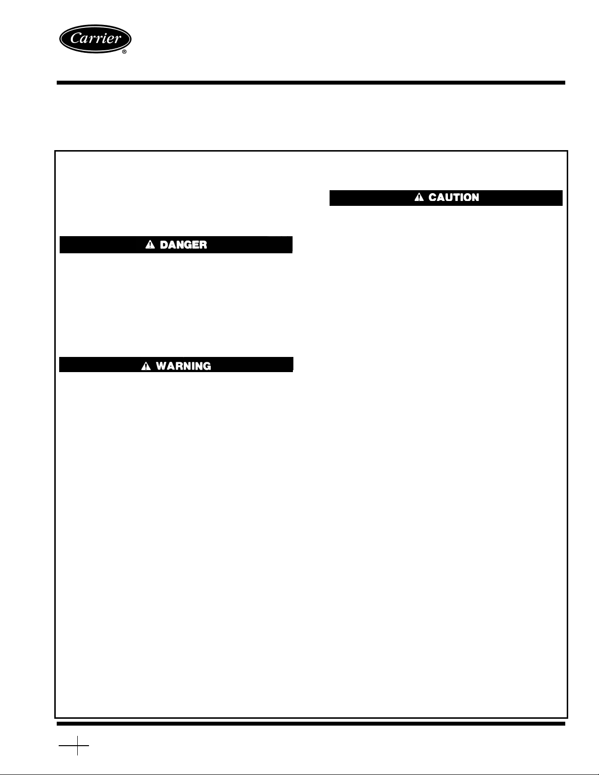
Machine Construction — The major sections of
the machine are contained in several vessels (Fig. 1- 4,
Table 1).
The large lower shell contains the evaporator section in
its upper part and the absorber section at the bottom. In the
evaporator,therefrigerantwatervaporizesinthe cooling cycle
and cools the chilled water for the air conditioning or cooling process. In the heating cycle, hot water vapor flows into
the evaporator section where it condenses and heats the hot
water for the heating process. The heat transfer tube bundle
in the evaporator is used for both cooling and heating. In the
absorber, vaporized refrigerant water is absorbed by lithium
bromide solution in the cooling cycle. In the heating cycle,
condensed refrigerant water from the evaporator drains into
the absorber where it is mixed with the strong solution.
The short vessel with the burner, located next to the
evaporator/absorber assembly,is the high-stage generator.The
vessel above it is the separator. In both the cooling and heating cycles, approximately half of the diluted lithium bromide solution is heated directly from the combustion of gas
or oil. The water vapor created in this process is released
from the reconcentrated solution in the separator vessel.
3
Page 4
The smaller shell above the evaporator/absorber assembly contains the low-stage generator and condenser. In the
cooling cycle, about half of the diluted lithium bromide
solution is heated and reconcentrated in the low-stage
generator by high-temperature vapor from the high-stage generator. The water vapor released from the solution in this
process is condensed to liquid in the condenser section. This
vessel is not used in the heating cycle, although about half
of the diluted solution does flow through the generator.
This chiller also has: 2 solution heat exchangers to improve operating economy; an external purge system to maintain machine vacuum by the continuous removal of noncondensables; 2 hermetic pumps to circulate the solution and
refrigerant; various operation, capacity, and safety devices
to provide automatic, reliable machine performance; and the
ability to manually switch between cooling and heating
operation.
Fig. 1 — 16DF Machine, Front View
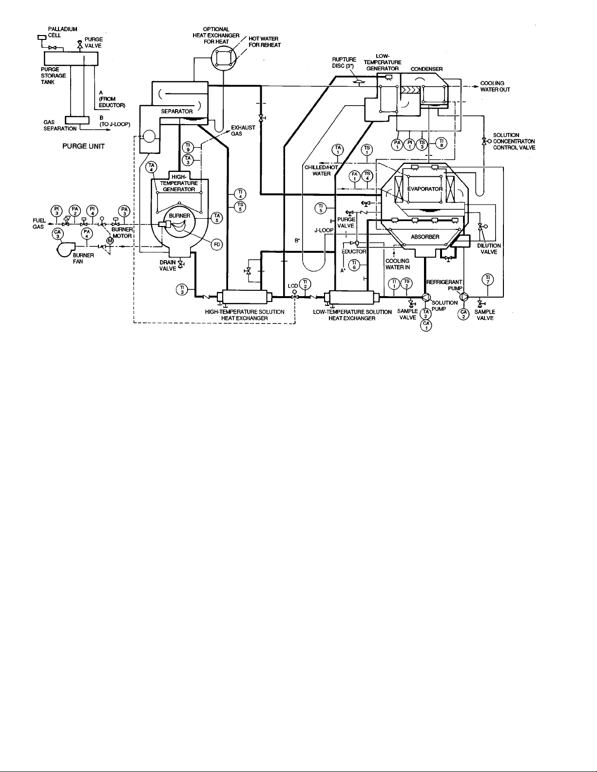
Fig. 2 — Machine Controls and Components, Schematic
4
Page 5
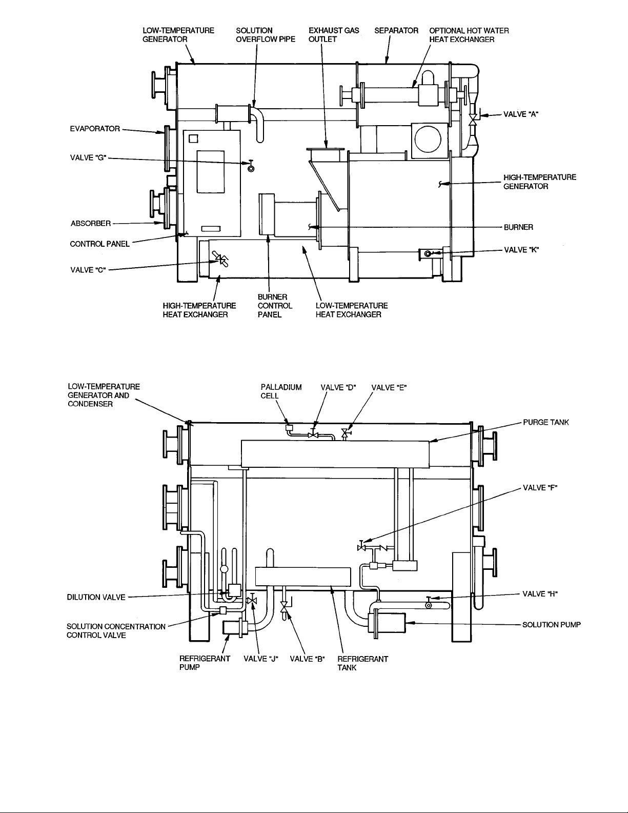
Fig.3—Valve and Component Locations, Front View
Fig.4—Valve and Component Locations, Rear View
5
Page 6

Table1—Valve Descriptions
VALV E US E
A Heating/Cooling Vapor
B Heating/Cooling Liquid
C Heat Exchanger Service
D Palladium Cell Isolation
E Purge Storage Tank Evacuation
F Auxiliary Evacuation
G Vacuum/Pressure Gage
H Solution Pump Service
J Refrigerant Pump Service
K High-Stage Generator Service
Cooling Cycle Flow Circuits — Figure 5 illustrates
the basic flow circuits of the 16DF absorption chiller during
the cooling cycle.
The liquid to be chilled is passed through the evaporator
tube bundle and is cooled by the evaporation of refrigerant
water sprayed over the outer surface of the tubes by the recirculating refrigerant pump. The refrigerant vapors are drawn
into the absorber section and are absorbed by the lithium
bromide-water solution sprayed over the absorber tubes. The
heat picked up from the chilled liquid is transferred from the
absorbed vapor to cooling water flowing through the absorber tubes.
The solution in the absorber becomes diluted as it absorbs
water, and loses its ability to continue the absorption. It is
then transferred by the solution pump to the generator sections to be reconcentrated. Approximately half of the weak
(diluted) solution goes to the high-stage generator where it
is heated directly by the combustion of gas or oil to boil out
the absorbed water. The mixture of reconcentrated solution
and vapor rises to the separator, where the vapor is released
and is then passed to the low-stage generator tubes. In the
low-stage generator, the rest of the weak solution is heated
by the high-temperature vapor from the high-stage separator, to boil out the remaining absorbed water.
The resulting water vapor from the low-stage generator
solution passes into the condenser section and condenses on
tubes containing cooling water.This is the same cooling water which had just flowed through the absorber tubes. The
condensed high-temperature water from the low-stage generator tubes is also passed over the condenser tubes where it
is cooled to the condenser temperature. The combined condensed refrigerant liquid, from the 2 generators, now flows
back to the evaporator to begin a new refrigerant cycle.
The strong (reconcentrated) solution flows from the 2 generators back to the absorber spray headers to begin a new
solution cycle. On the way, it passes through solution heat
exchangers where heat is transferred from the hot, strong solution to the cooler, weak solution being pumped to the generators. Solution to and from the high-stage generator passes
through both a high-temperature heat exchanger and a lowtemperature heat exchanger. Solution to and from the lowstage generator passes through only the low-temperature heat
exchanger,mixedwiththe high-stage generator solution. This
heat transfer improves solution cycle efficiency by preheating the relatively cool, weak solution before it enters the generators, and precooling the hotter, strong solution before it
enters the absorber.
During high-load cooling operation, some abnormal conditions can cause the lithium bromide concentration to increase above normal. When this happens, a small amount of
refrigerant is transferred by an evaporator overflow pipe into
the absorber solution to limit the concentration. This is necessary to keep the strong solution concentration away from
crystallization (see Solution Cycle and Equilibrium Diagram section, page 9).
The evaporator refrigerant level is directly related to machine solution concentration. As the concentration increases
(has less water), so does the refrigerant level. As the solution
concentration increases beyond a safe limit, the refrigerant
level rises to the level of the overflow pipe and some spills
over to flow into the absorber. The concentration at which
the refrigerant overflows is determined by the amount of refrigerant (water) which is charged into the machine.
If, for some reason, the machine controls and evaporator
overflow do not prevent strong solution crystallization during abnormal operating conditions, and flow blockage occurs, the strong solution overflow pipe will reverse or limit
the crystallization until the cause can be corrected. The overflow pipe is located between the low-temperature generator discharge box and the absorber, bypassing the heat
exchangers.
If crystallization occurs, it generally takes place in the shell
side of the low-temperature heat exchanger, blocking the flow
of strong solution from the generators. The strong solution
then backs up in the discharge box and spills over into the
overflow pipe, which returns it directly to the absorber sump.
The solution pump then returns this hot solution through the
heat exchanger tubes, automatically heating and decrystallizing the shell side.
Heating Cycle Flow Circuits — Figure 6 illustrates
the basic flow circuits of the 16DF absorption chiller during
the heating cycle.
The liquid to be heated is passed through the evaporator
tube bundle and is heated by condensation of hot water vapor from the high-stage generator. The solution flowing from
the absorber, through the heat exchangers to the generators
via the solution pump, and then back through the heat exchangers to the absorber sprays is basically the same as in
the cooling cycle. However, the solution is heated and reconcentrated only in the high-stage generator. The heating
refrigerant water cycle is quite different from that of the cooling cycle. The cooling water flow is turned off, as is the refrigerant recirculating pump.Thehigh-temperaturewatervapor
from the high-stage generator is diverted to the evaporator,
and the condensed vapor in the evaporator is drained directly to the absorber solution.
6
Page 7
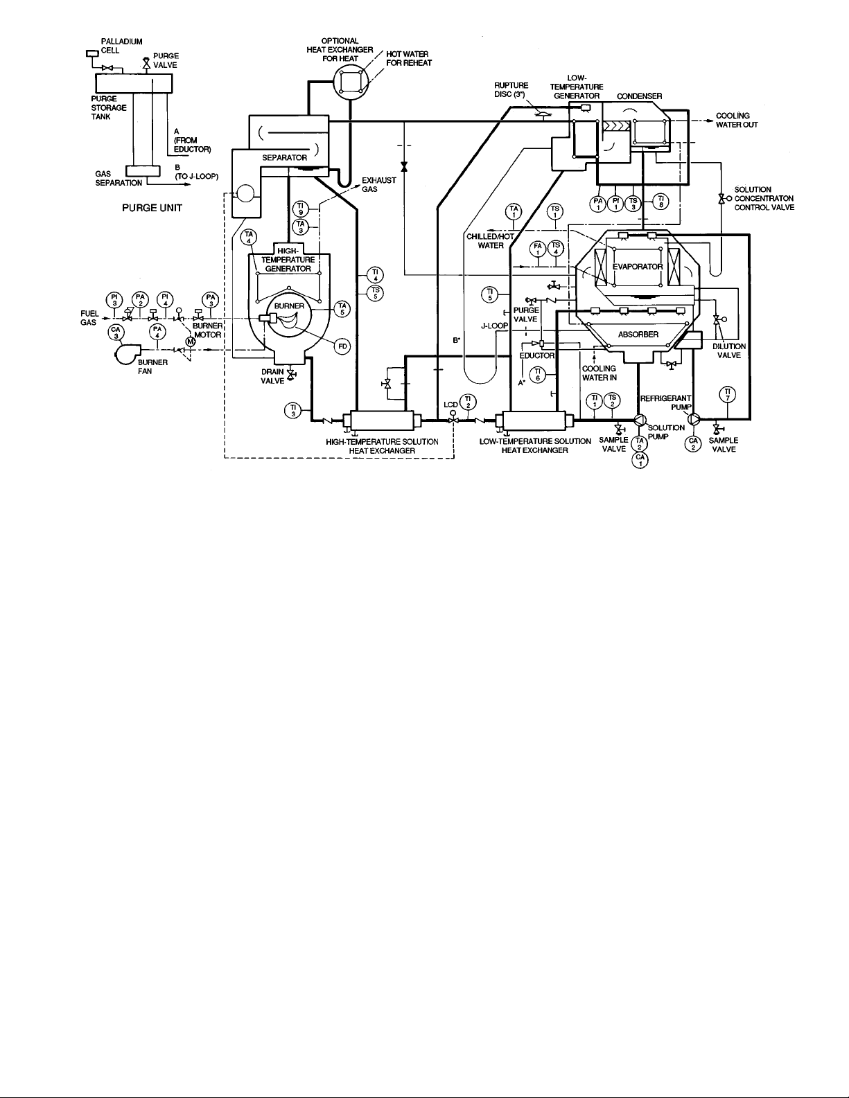
A,B — Connecting Piping from Purge
CA1 — Solution Pump Motor Overload
CA2 — Refrigerant Pump Motor Overload
CA3 — Burner Blower Motor Overload
FA1 — Chilled/Hot Water Flow Switch
FD — Burner Flame Detector
LCD — Level Control Device
M—Burner Firing Rate Positioning
PA1 — High-Temperature Generator High-
PA2 — Low Gas Pressure Switch
PA3 — High Gas Pressure Switch
PA4 — Low Combustion Air Pressure
*See Purge Unit insert.
NOTE: Service valve connections are
Unit Diagram to Machine Cycle
Diagram
Motor
Pressure Switch
Switch
1
⁄2-in. NPT.
LEGEND
PI1 — High-Temperature Generator
Pressure Gage
PI3 — Supply Gas Pressure Gage
PI4 — Regulated Gas Pressure Gage
TA1 — Chilled/Hot WaterTemperature Limit
TA2 — Solution Pump Motor High-
Temperature Limit
TA3 — Exhaust Gas High-Temperature
Limit
TA4 — Fire Tube High-Temperature Limit
TA5 — Return End Refractory
High-Temperature Limit
TI1-3 — Weak Solution Temperature
Measurement Wells
TI4-6 — Strong Solution Temperature
Measurement Wells
Fig. 5 — Cooling Cycle with Data Points
TI7 — Refrigerant Temperature
Measurement Well
TI8 — Refrigerant Condensate Tempera-
ture Measurement Well
TI9 — Exhaust Gas Temperature
Measurement Gage
TS1 — Leaving Chilled/Hot Water
Temperature Sensor
TS2 — Weak Solution Temperature
Sensor
TS3 — High-Temperature Generator
Vapor Temperature Sensor
TS4 — Entering Chilled/Hot Water
Temperature Sensor
TS5 — High-Temperature Generator
Strong Solution Temperature
Sensor
7
Page 8
A,B — Connecting Piping from Purge
CA1 — Solution Pump Motor Overload
CA2 — Refrigerant Pump Motor Overload
CA3 — Burner Blower Motor Overload
FA1 — Chilled/Hot Water Flow Switch
FD — Burner Flame Detector
LCD — Level Control Device
M—Burner Firing Rate Positioning
PA1 — High-Temperature Generator High-
PA2 — Low Gas Pressure Switch
PA3 — High Gas Pressure Switch
PA4 — Low Combustion Air Pressure
*See Purge Unit insert.
NOTE: Service valve connections are
Unit Diagram to Machine Cycle
Diagram
Motor
Pressure Switch
Switch
1
⁄2-in. NPT.
LEGEND
PI1 — High-Temperature Generator
Pressure Gage
PI3 — Supply Gas Pressure Gage
PI4 — Regulated Gas Pressure Gage
TA1 — Chilled/Hot WaterTemperature Limit
TA2 — Solution Pump Motor High-
Temperature Limit
TA3 — Exhaust Gas High-Temperature
Limit
TA4 — Fire Tube High-Temperature Limit
TA5 — Return End Refractory
High-Temperature Limit
TI1-3 — Weak Solution Temperature
Measurement Wells
TI4-6 — Strong Solution Temperature
Measurement Wells
Fig. 6 — Heating Cycle with Data Points
TI7 — Refrigerant Temperature
Measurement Well
TI8 — Refrigerant Condensate Tempera-
ture Measurement Well
TI9 — Exhaust Gas Temperature
Measurement Gage
TS1 — Leaving Chilled/Hot Water
Temperature Sensor
TS2 — Weak Solution Temperature
Sensor
TS3 — High-Temperature Generator
Vapor Temperature Sensor
TS4 — Entering Chilled/Hot Water
Temperature Sensor
TS5 — High-Temperature Generator
Strong Solution Temperature
Sensor
8
Page 9

Solution Cycle and Equilibrium Diagram — The
solution cycles for cooling and heating operation can be illustrated by plotting them on a basic equilibrium diagram
for lithium bromide in solution with water (Fig. 7 and 8).
The diagram is also used for performance analyses and
troubleshooting.
The left scale on the diagram indicates solution and water
vapor pressures at equilibrium conditions. The right scale
indicates the corresponding saturation (boiling or condensing) temperatures of the refrigerant (water).
The bottom scale represents solution concentration, expressed as percentage of lithium bromide by weight in solution with water. For example, a lithium bromide concentration of 60% means 60% lithium bromide and 40% water
by weight.
The curved lines running diagonally left to right are solution temperature lines (not to be confused with the horizontal saturation temperature lines). The single curved line
beginning at the lower right represents the crystallization line.
The solution becomes saturated at any combination of temperature and concentration to the right of this line, and it
will begin to crystallize (solidify) and restrict flow.
The slightly sloped lines extending from the bottom of the
diagram are solution-specific gravity lines. The concentration of a lithium bromide solution sample can be determined
by measuring its specific gravity with a hydrometer and reading its solution temperature. Then, plot the intersection point
for these 2 values and read straight down to the percent lithium
bromide scale. The corresponding vapor pressure can also
be determined by reading the scale straight to the left of the
point, and its saturation temperature can be read on the scale
to the right.
PLOTTING THE COOLING SOLUTION CYCLE — An
absorption solution cycle at typical full load conditions is
plotted in Fig. 7 from Points 1 through 12. The corresponding values for these typical points are listed in Table 2. Note
that these values will vary with different loads and operating
conditions.
Point 1 represents the strong solution in the absorber, as it
begins to absorb water vapor after being sprayed from the
absorber nozzles. This condition is internal and cannot be
measured.
Point 2 represents the diluted (weak) solution after it leaves
the absorber and before it enters the low-temperature heat
exchanger.Thisincludes its flow through the solution pump.
This point can be measured with a solution sample from the
pump discharge.
Point 3 represents the weak solution leaving the lowtemperature heat exchanger. It is at the same concentration
as Point 2 but at a higher temperature after gaining heat from
the strong solution. This temperature can be measured. At
this point, the weak solution is split, with approximately half
of it going to the low-stage generator,and the rest of it going
on to the high-temperature heat exchanger.
Point 4 represents the weak solution in the low-stage generator after being preheated to the boiling temperature. The
solution will boil at temperatures and concentrations corresponding to a saturation temperature established by the vapor condensing temperature in the condenser. This condition
is internal and cannot be measured.
Point 5 represents the weak solution leaving the hightemperature heat exchanger and entering the high-stage generator. It is at the same concentration as Points 2 and 3, but
at a higher temperature after gaining heat from the strong
solution. This temperature can be measured.
Point 6 represents the weak solution in the high-stage generator after being preheated to the boiling temperature. The
solution will boil at temperatures and concentrations corresponding to a saturation temperature established by the vapor condensing temperature in the low-stage generator tubes.
This condition is internal and cannot be measured.
Point 7 represents the strong solution leaving the high-stage
generator and entering the high-temperature heat exchanger
after being reconcentrated by boiling out refrigerant. It can
be plotted approximately by measuring the temperatures of
the leaving strong solution and the condensed vapor leaving
the low-stage generator tubes (saturation temperature). This
condition cannot be measured accurately.
Point 8 represents the strong solution from thehigh-temperature
heat exchanger as it flows between the 2 heat exchangers. It
is the same concentration as Point 7, but at a cooler temperature after giving up heat to the weak solution. It is an
internal condition and cannot be measured.
Point 9 represents the strong solution leaving the low-stage
generator and entering the low-temperature heat exchanger.
It is at a weaker concentration than the solution from the
high-stage generator, and can be plotted approximately by
measuring the temperatures of the leaving strong solution
and vapor condensate (saturation temperature). This condition cannot be measured accurately.
Point 10 represents the mixture of strong solution from the
high-temperature heat exchanger and strong solution from
the low-stage generator after they both enter the lowtemperature heat exchanger. It is an internal condition and
cannot be measured.
Point 11 represents the combined strong solution before it
leaves the low-temperature heat exchanger after giving up
heat to the weak solution. This condition is internal and cannot be measured.
Point 12 represents the strong solution leaving the lowtemperature heat exchanger and entering the absorber spray
nozzles, after being mixed with some weak solution in the
heat exchanger. The temperature can be measured but the
concentration cannot be sampled. After leaving the spray
nozzles, the solution is somewhat cooled and concentrated
as it flashes to the lower pressure of the absorber.
9
Page 10
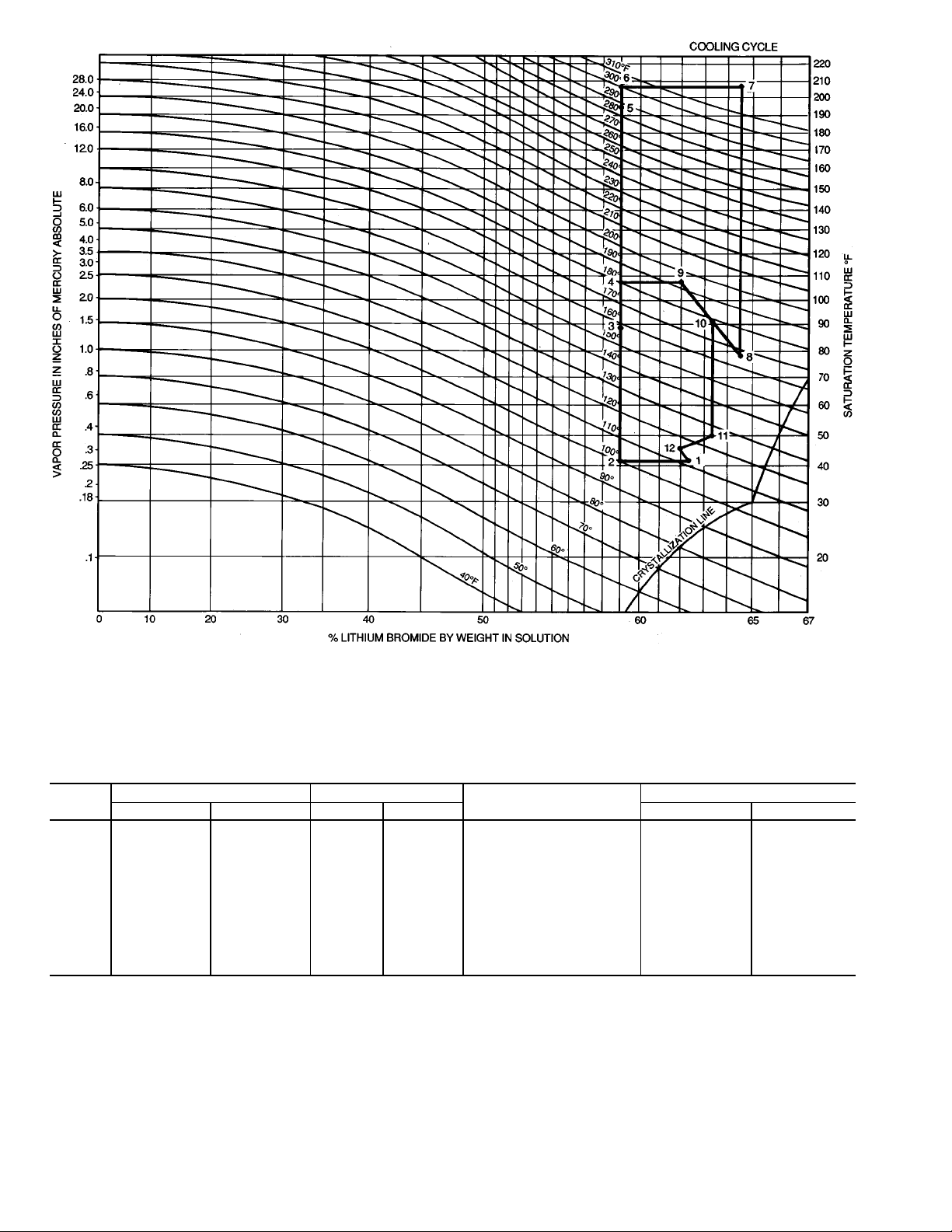
Fig. 7 — Equilibrium Diagram, Cooling Cycle
Table2—Typical Full Load Cooling Cycle Equilibrium Data
POINT
1 111 44 0.26 6.6 62.2 41 5
2 100 38 0.26 6.6 59.0 41 5
3 158 70 1.20 30.0 59.0 84 29
4 181 83 2.20 56.0 59.0 104 40
5 289 143 23.00 584.0 59.0 198 92
6 300 149 27.00 686.0 59.0 208 98
7 332 167 27.00 686.0 64.5 208 98
8 167 75 0.80 20.3 64.5 72 22
9 194 90 2.20 56.0 62.0 104 40
10 178 81 1.30 33.0 63.4 86 30
11 126 52 0.39 9.9 63.4 51 11
12 117 47 0.30 7.6 62.0 45 7
SOLUTION TEMPERATURE VAPOR PRESSURE
°F °C in. Hg mm Hg °F °C
SOLUTION PERCENTAGE
LITHIUM BROMIDE
SATURATION TEMPERATURE
10
Page 11

PLOTTING THE HEATING SOLUTION CYCLE —Aheating solution cycle at typical full load conditions is plotted in
Fig. 8 from Points 1 through 11. The corresponding values
for these typical points are listed in Table3.Theheating cycle
operates with lower (more dilute) solution concentrations than
used with the cooling cycle because most of the refrigerant
water is drained from the evaporator into the solution. Note
that these values will vary with different loads and operating
conditions.
Point 1 represents the strong solution in the absorber after
being sprayed from the absorber nozzles, before it begins to
mix with condensed water vapor draining from the evaporator. The temperature of the solution to the spray nozzles
can be measured, but the concentration cannot be sampled.
Point 2 represents the diluted (weak) solution, with the condensed water, leaving the absorber and entering the lowtemperature heat exchanger.Thispoint can be measured with
a solution sample from the pump discharge.
Point 3 represents the weak solution as it leaves the lowtemperature heat exchanger. It is at the same concentration
as Point 2 but at a slightly warmer temperature after gaining
some heat from the strong solution. This temperature can be
measured. At this point, the weak solution is split, with approximately half of it going to the low-stage generator, and
the rest of it going to the high-temperature heat exchanger.
Although the solution sent to the low-stage generator is not
used in the heating function, the solution distribution and
flow rates are maintained approximately the same as in the
cooling cycle to minimize piping and control differences.
Point 4 represents the weak solution as it leaves the hightemperature heat exchanger and enters the high-stage generator. It is at the same concentration as Points 2 and 3, but
at a higher temperature after gaining heat from the strong
solution. This temperature can be measured.
Point 5 represents the weak solution in the high-stage generator after being preheated to the boiling temperature. The
solution will boil at temperatures and concentrations corresponding to a saturated temperature established by the vapor
condensing temperature in the evaporator. This condition is
internal and cannot be measured.
Point 6 represents the strong solution leaving the high-stage
generator and entering the high-temperature heat exchanger
after being reconcentrated by boiling out refrigerant water.
The heat energy in the vapor produced in this process is used
directly for heating the circulating hot water in the evaporator. The leaving strong solution temperature can be measured but the saturation temperature cannot be measured accurately to plot the point.
Point 7 represents the strong solution from thehigh-temperature
heat exchanger as it flows between the two heat exchangers.
It is the same concentration as Point 6, but at a cooler temperature after giving up heat to the weak solution. It is an
internal condition and cannot be measured.
Point 8 represents the weak solution leaving the low-stage
generator and entering the low-temperature heat exchanger.
It is at a slightly higher concentration than the entering solution because it has picked up some heat from the hot vapor
in the generator tubes, as an incidental occurrence in the flow
process.
Point 9 represents the mixture of strong solution from the
high-temperature heat exchanger and the weak solution from
the low-stage generator after they both enter the lowtemperature heat exchanger. It is an internal condition and
cannot be measured.
Point 10 represents the combined strong solution before it
leaves the low-temperature heat exchanger, after giving up
heat to the weak solution. This is an internal condition and
cannot be measured.
Point 11 represents the strong solution leaving the lowtemperature heat exchanger and entering the absorber spray
nozzles, after being mixed with some weak solution in the
heat exchanger. The temperature can be measured, but the
concentration cannot be sampled. After leaving the spray
nozzles, the solution is somewhat cooled and concentrated
as it flashes to the lower pressure of the absorber.
11
Page 12

Fig. 8 — Equilibrium Diagram, Heating Cycle
Table3—Typical Full Load Heating Cycle Equilibrium Data
POINT
1 188 87 4.1 104 54.4 127 53
2 188 87 6.4 163 50.5 142 61
3 199 93 8.0 203 50.5 152 67
4 248 120 21.0 533 50.5 199 93
5 255 124 24.0 610 50.5 207 97
6 307 153 24.0 610 60.6 207 97
7 195 91 2.8 71 60.6 113 45
8 202 94 8.0 203 51.5 152 67
9 198 92 4.7 119 56.0 130 54
10 190 88 4.0 102 56.0 125 52
11 190 88 4.9 124 54.0 131 55
SOLUTION TEMPERATURE VAPOR PRESSURE
°F °C in. Hg mm Hg °F °C
SOLUTION PERCENTAGE
LITHIUM BROMIDE
SATURATION TEMPERATURE
12
Page 13
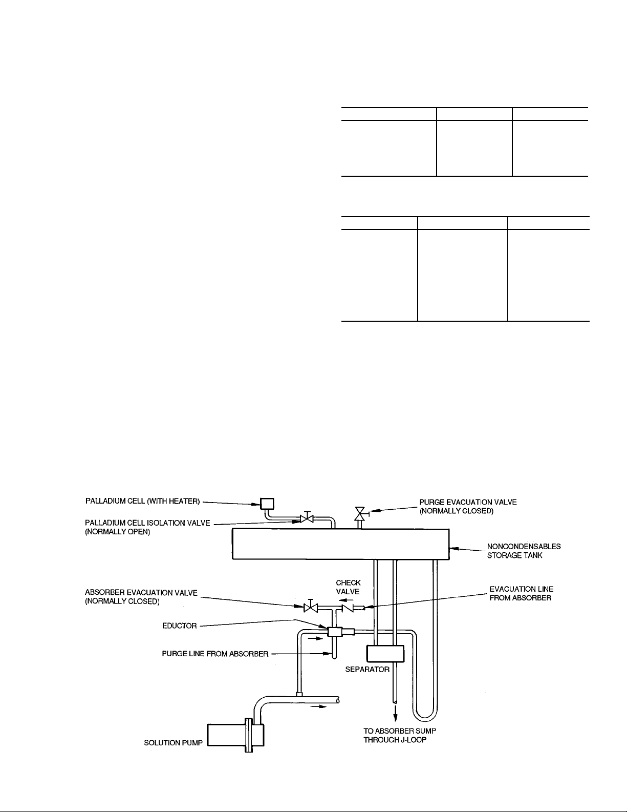
Purge — The basic components and flow circuits of the
motorless purge are shown in Fig. 9.
The purge system automatically removes noncondensables from the machine and transfers them to a storage chamber where they cannot affect machine operation.
Noncondensables are gases which will not condense at the
normal chiller operating temperatures and pressures (N
, etc.) and, because they reduce the machine vacuum, they
H
2
would also reduce the machine capacity.
Hydrogen (H
normal operation, and its rate of generation is controlled by
) gas is liberated within the machine during
2
the solution inhibitor. The presence of most other gases in
the machine would occur either through a leak (the machine
is under a deep vacuum) or during service activities.
While the machine is operating, any noncondensables accumulate in the absorber which is the lowest pressure area
of the machine.
For purging, noncondensables are continuously drawn from
the absorber into the lower pressure of an eductor, where
they are entrained in solution flowing from the solution pump.
The mixture then continues on to the purge storage tank. The
noncondensables are released in a separator and the solution
flows back to the absorber by way of the generator overflow
pipe. Typicallymost of the noncondensable gas is hydrogen,
which is automatically passed out to the atmosphere through
a heated palladium membrane cell.
Any other gas accumulates in the purge storage tank where
it is isolated from the rest of the machine. It is then removed
from the storage tank, when necessary, by a vacuum pump
connected to the tank exhaust valve. If the machine is maintained in a leak-tight condition, as it should be, the storage
tank is normally exhausted once or twice a year, during a
normal shutdown period or seasonal changeover. When it is
necessary to remove noncondensables directly from the machine, such as after service work, a vacuum pump can be
connected to the auxiliary evacuation valve, which is connected directly to the absorber through an isolation check
valve.
2,O2
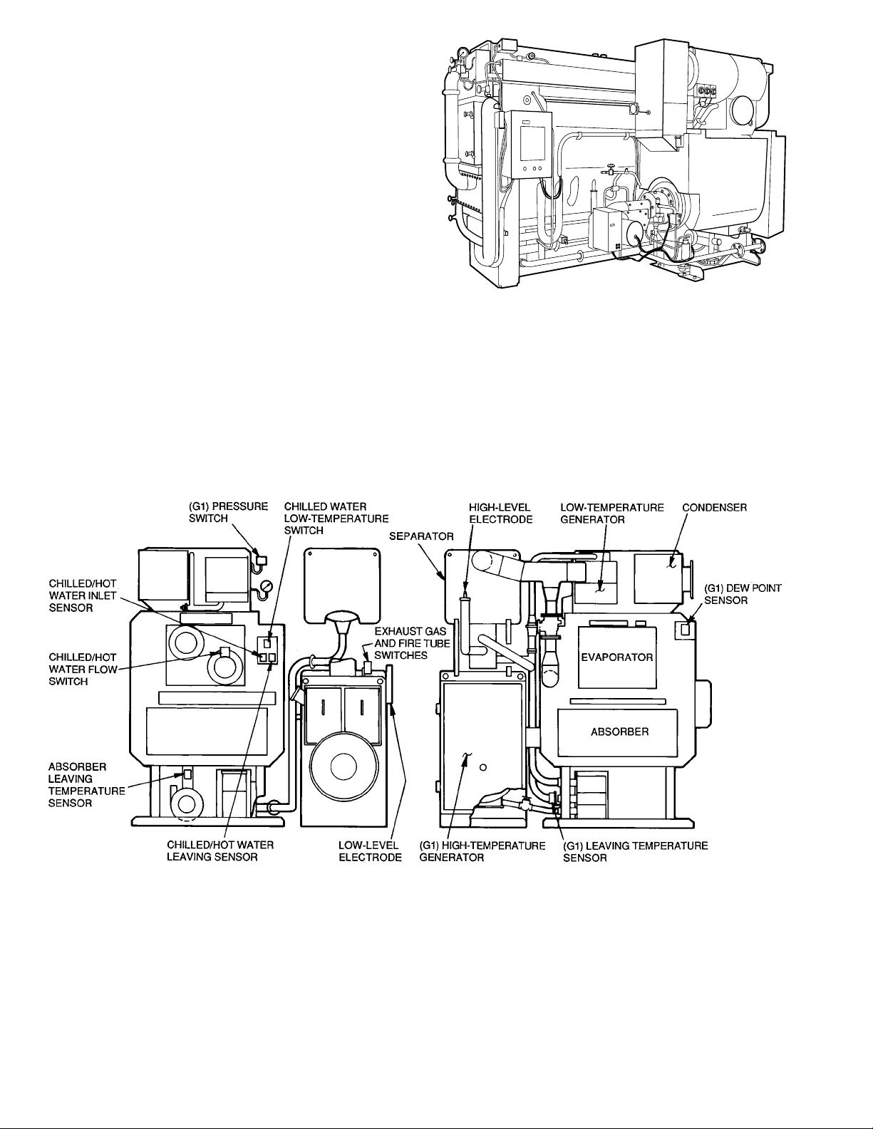
Operation Status Indicators — The 16DF absorp-
tion chiller/heater is equipped with several instruments and
sight glasses for direct observation of its operation in addition to a digital display of the temperature sensed for machine control and for codes (Tables 4 and 5).
,
DESCRIPTION LOCATION FUNCTION
High-Temperature
Generator Compound
Gage
Exhaust Gas
Thermometer
Table 4 — 16DF Instruments
Low-Temperature
Generator
Steam Chamber
High-Temperature
Generator
Exhaust Stack
High-Temperature
Generator
Vessel Pressure
Exhaust Gas
Discharge
Temperature
Table 5 — 16DF Sight Glass
DESCRIPTION LOCATION FUNCTION
Absorber Sight
Glass
High-Temperature
Generator
Sight Glass
Combustion
Chamber
Sight Glass
Evaporator Refrigerant
Overflow Pipe
High-Temperature
Generator Level
Control Device Box
High-Temperature
Generator
Combustion Chamber
Return End
Absorber
Liquid Level
Refrigerant Overflow
High-Temperature
Generator
Liquid Level
Combustion and
Refractory
Insulation
Status
Burner — The burner is a packaged, forced-draft type,
with modulating firing rate control. It is supplied with components selected for operation with either gas, light oil, or
both fuels, and with appropriate safety and control components to comply with specified code, insurance, and jurisdictional agency requirements.
Specific information is contained in the burner manual ac-
companying each burner.
Fig. 9 — Purge System
13
Page 14

MACHINE CONTROLS
This machine uses a microprocessor control system. Do
not short or jumper between terminations on printed circuit boards. Control or board failure may result. Also,
when performing welding, wiring, or an insulation resistance test on the machine, disconnect wiring to the
CPU (Control Processing Unit) board to avoid risk of
voltage damage to the board components.
Be aware of electrostatic discharge (static electricity)
when handling or making contact with the printed circuit boards. Always touch a grounded chassis part to
dissipate body electrostatic charge before working inside the control center.
Use extreme care when handling tools near boards
and when connecting or disconnecting terminal plugs.
Circuit boards can easily be damaged. Always holdboards
by edges and avoid touching components and pin connections. Always store and transport replacement or defective boards in anti-static bags.
General — The 16DF machine uses a microprocessor-
based control center which monitors and controls all operations of the machine. It also has a separate burner control
center, under direction of the machine control center, to provide burner sequence control and combustion supervision.
The integrated control system matches the cooling and heating capacities of the machine to the respective cooling and
heating loads, while providing state-of-the-art machine
protection.
The system controls the machine output temperatures within
the set point deadband by sensing the leaving chilled and hot
water temperatures and regulating the burner heat input accordingly. Machine protection is provided by continuously
monitoring critical conditions and performing control overrides or safety shutdowns, if required.
Start-Stop System — The type of start-stop system is
selected by the customer. The most commonly used systems
are described below. Review the descriptions and determine
which system applies to your job.
SEMIAUTOMATIC START-STOP — In this basic system,
auxiliary equipment is wired into the machine control circuit and machine is started and stopped manually with the
machine Start and Stop switches. Two variations are used:
With Pilot Relays — The coils for the chilled/hot water and
condensing water pump starters (or other auxiliary equipment) are wired into the machine control circuit so that the
auxiliary equipment operates whenever machine operates. The
starter contacts and starter overloads remain in the external
pump circuits. The pump flow switch(es) and auxiliary starter
circuits are also wired into the machine control circuit and
must be closed for the machine to operate.
WithManualAuxiliaries — With this system, the auxiliaries
must be started manually and independently from the machine start, and they must be operating before the machine
can start. As with the pilot relay system above, the flow
switch(es) and auxiliary starter contacts are in the machine
control circuit and must be closed for the machine to
operate.
FULL AUTOMATIC START-STOP — This system is basically the same as the semiautomatic system with pilot relays described above. Machine and auxiliary start and stop,
however are controlled by a field-supplied thermostat, timer,
or other automatic device when the TS6 Local/Remote switch
is in the REMOTE position, and the machine Start switch
has been depressed.
Machine Control Panel — The 16DF standard con-
trol panel is shown in Fig. 10.
LEGEND
3CI — Three-Character Indicator
51RP — Refrigerant Pump Overcurrent Relay
51SP — Solution Pump Overcurrent Relay
88RP — Refrigerant Pump Electromagnetic
88SP — Solution Pump Electromagnetic
BZ — Alarm Buzzer
CX — Remote Control Auxiliary Relay*
DL — Door Latch
ET1,2 — Grounds
F0 — End-Contact Fuse
F1-5 — Enclosed Fuses
MCB1,2 — Main Circuit Breakers
NF1,2 — Line Noise Filters
PB1 — Start Pushbutton Switch
PB2 — Stop Pushbutton Switch
PK1 — Central Processing Unit (CPU) Board
PK2 — Input Terminal Module
PK3 — Output Terminal Module
RY1 — External Emergency Stop Auxiliary Relay
RY2-5 — Burner Safety Shutdown Auxiliary Relays
SK1-3 — Surge Suppressors
ST1 — Display Code Identification Sticker
SWR1,2 — Switching Regulators
T1 — Burner Safety Shutdown (‘‘Off’’ Delay Timer)
TB1-3 — Terminal Boards
TR1 — Transformer
TR2 — Direct Current Control Circuit
TR3 — Alternating Current Control Circuit Transformer
TS2-6 — Operation Switches
TS1 — Direct Current Power Supply (On/Off)
TX — Remote Control Circuit Auxiliary Relay*
*CX,TX auxiliary relays for remote operation are
optionally installed signals.
Contactor
Contactor
(see also Fig. 11)
Transformer
Fig. 10 — Control Panel
14
Page 15

Status Indicator Sticker — The sticker shown in
Fig. 11 is located on the front of the control panel. It identifies the basic codes for machine operating status and safety
shutdown, as displayed by the 3-character indicator on the
front of the control panel.
NOTE: See Digital Temperature Display, page 16, and Adjustment Switches, below, for switch selections that display
temperatures being measured by the machine sensors as well
as the machine cumulative run time.
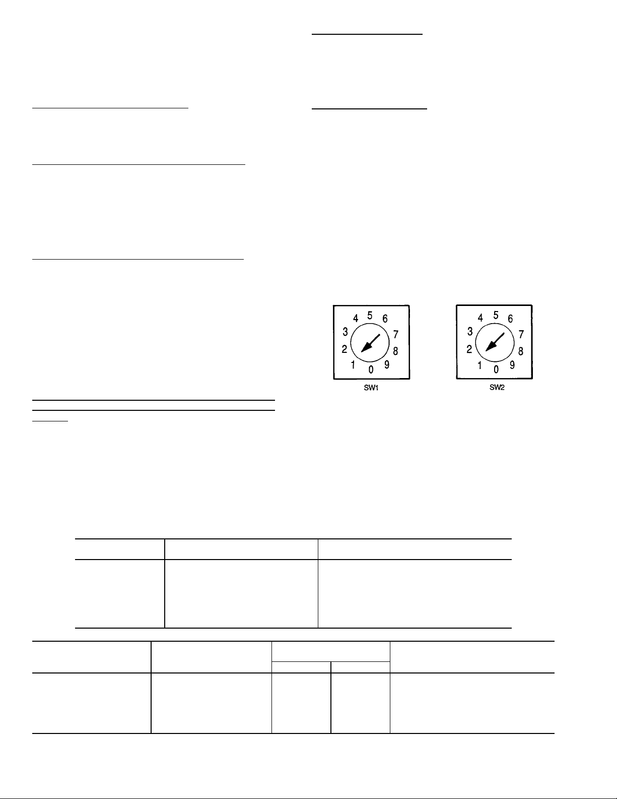
Adjustment Switches — These are located on the cir-
cuit board on the inside panel door.
TOGGLE SWITCHES (Fig. 12) — These are summarized
in Table 6 and discussed in greater detail in various sections
throughout this manual.
Table 6 — Control Panel Toggle Switches
SYMBOL TOGGLE SWITCH DESCRIPTION
TS1 On-Off Direct Current Power Supply
TS2 Auto.-Manual Dilution Valve
TS3 Cool-Heat Select Cool/Heat
TS4 Open-Close Capacity Control Valve
TS5 Auto.-Manual Capacity Control Valve
TS6 Remote-Local Operation
NOTES:
1. Time display selection shows thecumulative machine operating time inhours
on the panel door operating status indicator. With the capacity control valve
selection in the AUTO. position, momentarily depressing the switch to OPEN
displays the first 3 digits of the time, and depressing the switch to CLOSE
displays the last 2 digits and decimal. Example:
OPEN position indicates = 012
CLOSE position indicates = 345
Cumulative run time = 01234.5 hours
2. With capacity control valve selection in the MANUAL position, momentarily
depressing the switch to OPEN or CLOSE will move the burner fuel control
valve and air damper proportionally open or closed.
Fig. 12 — Control Panel Toggle Switches
Fig. 11 — Control Panel Status Indicator Sticker
15
Page 16
SET POINT AND DIP (Dual In-Line Package) SWITCHES
(Fig. 13-16) — These switches are used to adjust chilled water and hot water capacity control temperature set points (also
see Automatic Capacity Control section, page 31); to select
the type of remote control signal; to display temperatures of
the various machine temperature control sensors; and for service selections.
Chilled/Hot Water Control Location — SW11 switch 2
(Fig. 16) determines whether the capacity controller will use
the chilled/hot water inlet nozzle sensor (UP position), or
the outlet nozzle sensor (DOWN position).
NOTE: DOWN is the typical selection.
Chilled Water Capacity Control TemperatureSetPoint — The
chilled water control temperature is determined by the setting on SW2 (Fig. 13, right side). The settings are increments of 1° C (1.8° F) from 0° to 9° C (0° to 16° F), and the
control temperature is the SW2 setting above a base temperature of 5 C (41 F), for an adjustable range of 5 to 14 C
(41 to 57 F). For example, a selection of 2 on SW2 would
be a setting of 2° C plus5C(7Ctotal) (3.6° F plus 41 F =
44.6 F total).
Hot Water Capacity Control Temperature Set Point — The
hot water control temperature is determined by the settings
on SW1 (Fig. 13, left side) and on SW10 switches 1 and 2
(Fig. 15). The SW1 settings are increments of 1° C (1.8° F)
from 0° C to 9° C (0° to 16° F). The SW10 1 and 2 selections are for a base temperature of either 40 C (104 F),
50 C (122 F), 60 C (140 F), or 70 C (158 F). The control
temperature is the SW2 setting above the selected base
temperature, for an adjustable range of 40 to 79 C (104 to
174 F). For example, a selection of 2 on SW1 and placing
both SW10 switches in the UP position would be a setting
of 2° C plus 70 C (72 C total) (3.6 F plus 158 F =
161.6 F total).
Remote ON/OFF Signal — When the Local/Remote Operation toggle switch (Fig. 12) is in the REMOTE position, SW11
switch 1 (Fig. 16) will determine whether the remote signal
is to be a remotely powered on/off voltage signal to the machine control circuit (UP position), or is from machine control circuit power through remote dry contacts (DOWN
position).
Digital Temperature Display — The temperatures being measured by the machine’s analog sensors will be displayed in
°C by the 3-character indicator on the front of the control
panel when DIP switch 6 on SW11 (Fig. 16) is placed in the
UPposition.OtherwisethisswitchshouldbeleftintheDOWN
position for normal operating status indication. The temperatures will be shown in 8 sequential displays, with the
first of the 3 characters indicating the channel (sensor) and
the second and third characters showing the temperature. The
first 6 channels indicate temperatures of 0° to 99 C (32 to
210 F) directly, and the seventh indicates, by code, 0° to 200
C (32 to 392 F). See Table 7.
Indicator LEDs — Fig. 17 shows the status of the ma-
chine’s light-emitting diode (LED) indicator lights for DIP
switch 5 of SW11 (Fig. 16).
Chilled and Hot Water Temperature Limit Settings on SW9
(Fig. 14) and Capacity Control Response Speed on SW10
(Fig. 15) — The purpose and selection of these settings are
SW1 — Hot Water Temperature Setting
SW2 — Chilled Water Temperature Setting
explained in the Automatic Capacity Control section.
Table 7 — Digital Temperature Display Codes
FIRST CHARACTER SECOND AND THIRD CHARACTERS
CHANNEL NUMBER (TEMPERATURE IN °C)
0 00 to 99 Chilled/hot water leaving temperature
1 00 to 99 Weak solution leaving absorber temperature
2 00 to 99 High-stage generator vapor temperature
3 00 to 99 Chilled/hot water entering temperature
4 — Not used at this time
5 — Not used at this time
6 — Not used at this time
7 Code display High-stage generator leaving solution temperature
CHANNEL 7
TEMPERATURE CODE
7
*Example: A display showing 7C3 means channel 7 measures 123 C (253.4 F).
SECOND CHARACTER
CODE
A 100 212
B 110 230
C 120 248
D 130 266
E 140 284
F 150 302
H 160 320
TEMPERATURE
CF
Fig. 13 — Load Water Temperature
Adjustment Switches
CONDITION SENSED
BASE
THIRD CHARACTER
This is the unit of temperature
in 1° C increments (1.8° F) added to
the base temperature*
16
Page 17
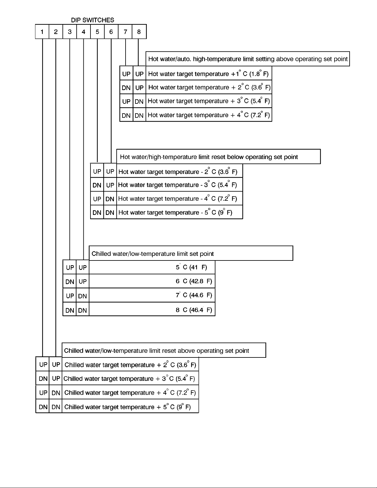
Fig. 14 — Switch SW9
17
Page 18

Fig. 15 — Switch SW10
LEGEND
DN — Down
Indicates typical setting
*—Priority over error number
Fig. 16 — Switch SW11
18
Page 19

Fig. 17 — LED Indicator Lights Status
Remaining Time Indication for Dilution Cycle
To view remaining time in minutes on the control panel
—
indicator, depress the Stop button (PB2) during the shutdown dilution cycle operation. It will be displayed only while
the button is depressed.
The following example indicates 12 minutes still remain
before dilution cycle is completed:
Dilution Cycle Indication — dPP
Depress Stop Button (PB2)
Remaining Time Indication — d12
Control Wiring — Figures 18-23 represent typical ma-
chine wiring schematics and component identification. See
machine control panel diagram (Fig. 10) for component location. Refer to burner manufacturer’s manual for burner control wiring diagram and component identification.
19
Page 20

LEGEND FOR WIRING DIAGRAMS (Fig. 18 - 23), Pages 20 - 25
3CI — Three-Character Indicator
20CCV — Concentration Control Valve Positioner
21CV — Burner Capacity Control Positioner
20DV — Dilution Valve
26CA — Fire Tube High-Temperature Switch
26EH — Burner Exhaust Gas High-Temperature Switch
26SP — Solution Pump High Motor Temperature Switch
51BF — Burner Blower Motor Overload Relay
51RP — Refrigerant Pump Overload Relay
51SP — Solution Pump Overload Relay
69CW 1,2 — Chilled Water and Cooling Water Flow Switches
86X — Burner Safety Auxiliary Relay
88BF — Burner Blower Motor Starter
88CP — Cooling Water Pump Starter
88EP — Chilled/Hot Water Pump Starter
88CT — Cooling Tower Fan Starter
88RP — Refrigerant Pump Starter
88SP — Solution Pump Starter
AR1-8 — Machine Control Relays
BCB — Burner Control Box
BZ — Alarm Buzzer
C/H — Chiller/Heater
CX — Remote Control Auxiliary Relay*
CN1-10 — Wiring Cable Connectors
ET1,2 — Grounds
F0 — End-Contact Fuse
F1-5 — Enclosed Fuses
G1 — High-Stage Generator
GH — High-Stage Generator, High-Solution Level Switch
M1-3 — Three-Phase Motors
MCB1,2 — Main Circuit Breakers
MCP — Machine Control Panel
NF1,2 — Line Noise Filters
PB1 — Start Pushbutton
PB2 — Stop Pushbutton
PK1 — Main Circuit Board
PK2 — Input Terminal Circuit Board
PK3 — Output Terminal Circuit Board
RY1 — External Emergency Stop Auxiliary Relay
RY2-5 — Burner Safety Shutdown Auxiliary Relays
SK1-3 — Surge Suppressors
ST1 — Display Code Identification Sticker
SWR1,2 — Switching Regulators
T1 — Burner Safety Shutdown (‘‘Off’’ Delay Timer)
T3H, T4H — Temperature Sensors
TB — Terminal Boards
TR1 — Transformer
TR2 — Direct Current Control Circuit Transformer
TR3 — Alternating Current Control Circuit Transformer
TS1 — Direct Current Power Supply (On/Off)
TS2-6 — Operation Switches
TX — Remote Control Circuit Auxiliary Relay*
Factory Wiring
Field Wiring
Optional Wiring
*CX, TX auxiliary relays for remote operation are optionally installed
signals.
NOTES:
1. BCB — installed in burner control box.
2. F — installed on chiller/heater.
Fig. 18 — Control Panel Power Wiring Schematic
20
Page 21

Fig. 19 — Terminal Strip, External Wiring Connections
21
Page 22

Fig. 20 — Circuit Board Wiring Locations
22
Page 23

NOTES:
1. PK3 — mounted on output terminal module in control panel.
2. Legend on page 20.
Fig. 21 — PK3 Circuit Board Output Wiring Connections
23
Page 24

Fig. 22 — PK2 Circuit Board Input Wiring Connections
24
Page 25

NOTES:
1. When the contacts of external emergency stop signals are connected, remove the jumper wire between terminal R2 and X4 and
connect external contacts to these terminals.
2. BCB — installed in burner control box.
3. F — Positioning motor.
4. PK2 — input terminal module in control panel.
5. PK3 — output terminal module in control panel.
Fig. 23 — PK2 and PK3 Partial Wiring Connections
REMOTE OPERATION CIRCUIT
Typical Control Sequence — Normal Cooling
Start (Fig. 24)
1. When power is supplied to the chiller control panel and
the machine is not in operation, the status indicator will
display ‘‘000’’.
2. For starting, the machine and burner switches should be
positioned as shown in Table 8, and the manual cooling/
heating valves positioned for cooling (Table 9).
NOTE: The Cool switch selection must be made before
the Start button is depressed.
3. When the Start button is depressed, the microprocessor
will initiate the timed starting and system checks sequence. The chilled water pump will be started, if not already running.After20seconds, the pump run interlock(s)
will be checked to verify if the pump is running. If it is,
the status indicator will display ‘‘CPO’’. If not, the sequence will be halted until the interlocks show the pump
is running.
4. The capacity controller then will be queried to see if there
is a need for cooling. If not, the sequence will be halted.
If cooling isrequired,thecoolingwaterpumpwill be started,
if not already running. After 20 seconds, the pump run
interlock(s) will be checked to verify it is running. If it is,
the start sequence will proceed. If not, the sequence will
be halted until the interlocks show the pump is running.
When the pump is running, the status indicator will display ‘‘CPP’’.
5. The cooling water temperature will be checked and, if it
is not too low,the cooling tower fan will be started, if not
already running. The status indicator will now display
‘‘CPP’’. At the same time, the solution pump and burner
will be started. The refrigerant pump will be started after
a short time delay. The chiller is now in normal
operation. The control system will continuously monitor
the capacity controller for load requirements, the safety
interlocks for abnormal conditions, and operating limits
for override control when necessary.
Typical Control Sequence — Normal Heating
Start (Fig. 24)
1. When power is supplied to the chiller control panel and
the machine is not in operation, the status indicator will
display ‘‘000’’.
2. For starting, the machine and burner switches should be
positioned as shown in Table 8, and the manual cooling/
heating valves positioned for heating (Table 9).
NOTE: The Heat switch selection must be made before
the Start button is depressed.
3. When the Start button is depressed, the microprocessor
will initiate the timed starting and system checks sequence. The hot water pump will be started, if not already running.After20seconds, the pump run interlock(s)
will be checked to verify it is running. If it is, the status
indicator will display ‘‘HPO’’. If not, the sequence will
be halted until the interlocks show the pump is running.
4. The capacity controller then will be queried to see if there
is a need for heating. If not, the sequence will be halted.
If there is, the start sequence will proceed.
5. The solution pump and the burner will be started. The
status indicator will display ‘‘HPO’’. The heater is now
in normal operation. The control system will continuously monitor the capacity controller for load requirements, the safety interlocks for abnormal conditions, and
operating limits for override control when necessary.
25
Page 26

NOTE: ‘‘XXX‘‘ represents letters for indicator on control panel.
Fig. 24 — Normal ‘‘Start’’ Flow Chart
26
Page 27

Table 8 — Switch Positions for Start-Up
MACHINE CONTROL PANEL
SYMBOL DESCRIPTION TOGGLE SWITCH SETTING
TS1 Direct Current Power Supply On-Off ON
TS2 Dilution Valve Auto.-Manual AUTO.
TS3 Select Cool/Heat Cool-Heat COOL OR HEAT
TS4 Capacity Control Valve Open-Close (NEUTRAL)
TS5 Capacity Control Valve Auto.-Manual AUTO.
TS6 Operation Remote-Local REMOTE OR LOCAL
BURNER CONTROL PANEL
DESCRIPTION TOGGLE SWITCH SETTING
Burner Control On-Off ON
Firing Rate Selector Auto.-Manual AUTO.
Firing Position Open-Stop-Close STOP
Fuel Selection (if used) Gas-Oil GAS OR OIL
Table 9 — 16DF Valves
MANUAL VALVES
NO. SYMBOL DESCRIPTION LOCATION OPERATION*
1 A Heating/Cooling Vapor Valves High-Temperature Vapor Discharge Pipe
2 B Heating/Cooling Liquid Valve Underside Refrigerant Tank
3 C Heat Exchanger Bypass Solution Heat Exchanger
4 D Palladium Cell Isolation Palladium Cell Connection Pipe
5 E Purge Storage Tank Evacuation Purge Tank
6 F Auxiliary Evacuation Purge Pipe
7 G Vacuum/Pressure Gage Connection Absorber Shell
8 H Solution Pump Service Solution Pump Discharge
9 J Refrigerant Pump Service Refrigerant Pump Discharge
10 K High-Stage Generator Service Underside High Temperature Generator
*Valve positions—O=FULLY OPEN; C = FULLY CLOSED.
Cooling Cycle C
Heating Cycle O
Cooling Cycle C
Heating Cycle O
Normal Operation C
Service O
Normal Operation O
Service C
Normal Operation C
Purge Discharge O
Normal Operation C
Machine Evacuation O
Normal Operation C
Vacuum/Pressure Check O
Normal Operation C
Service O
Normal Operation C
Service O
Normal Operation C
Service O
AUTOMATIC VALVES
NO. SYMBOL DESCRIPTION LOCATION OPERATION*
1 21CV Capacity Control Valves Burner Fuel Line and Air Damper Proportional between high fire and low fire
2 — Fuel Valves Burner Fuel Line
3 20DC Dilution Valve Evaporator Refrigerant Overflow Pipe
4 20CCV Concentration Control Valve Condenser Refrigerant Return Pipe
5 LCD Solution Flow Control Weak Solution Pipe
*Valve positions—O=FULLY OPEN; C = FULLY CLOSED.
Burner On O
Burner Off C
Dilution Cycle O
Normal Operation C
Concentration Control Cycle O
Normal Operation C
Reduces flow for low loads and low cooling water
temperature.
27
Page 28

Typical Control Sequence — Normal Cooling
Stop (Fig. 25)
1. The timed shutdown sequence begins when the Stop button is depressed or the capacity controller senses there is
insufficient load for continued operation. The status indicator will display ‘‘dPP’’.
2. The burner control is given a signal to move to the lowfire position, and, after 30 seconds, combustion is stopped
and the burner goes through its post-purge shutdown
sequence.
3. The refrigerant pump is stopped, and the dilution valve is
opened to drain refrigerant from the evaporator into the
absorber solution. The valve remains open until the shutdown is complete, and the refrigerant flow continues until the evaporator level reaches the level of the drain pipe.
4. Five minutes after the stop sequence is initiated, the solution temperature is checked to be sure it is cool enough
to stop the cooling water flow. When it is, the cooling
tower fan and cooling water pump are stopped if
they are connected to the control circuit for automatic
operation.
5. Fifteen minutes after the stop sequence is initiated, the
solution pump is stopped, and the machine shutdown is
completed. The pump remains in operation during the dilution period to mix refrigerant through the solution.
6. If the chilled water pump is connected to the control circuit for automatic operation, and the shutdown was initiated by the capacity controller, the chilled water pump
will continue running to be ready for a restart, and the
status indicator will display ‘‘APO’’. With a manual stop,
the chilled water pump will be stopped and the status indicator will display ‘‘000’’.
IMPORTANT :With manual pump control,thechilled
water pump must not be stopped until the shutdown cycle has been completed.
Typical Control Sequence — Normal Heating
Stop (Fig. 25)
1. The timed shutdown sequence begins when the Stop button is depressed or the capacity controller senses there is
insufficient load for continued operation. The status indicator will display ‘‘dPO’’.
2. The burner control is given a signal to move to the lowfire position, and, after 30 seconds, combustion is stopped
and the burner goes through its post-purge shutdown
sequence.
3. Fifteen minutes after the stop sequence is initiated, the
solution pump is stopped, and the machine shutdown is
completed. The pump remains in operation during the shutdown period to cool the solution and machine.
4. If the hot water pump is connected to the control circuit
for automatic operation, and the shutdown was initiated
by the capacity controller, the hot water pump will continue running to be ready for a restart, and the status indicator will display ‘‘APO’’. With a manual stop, the hot
water pump will be stopped and the status indicator will
display ‘‘000’’.
IMPORTANT: With manual pump control, the hot
water pump must not be stopped until the shutdown cycle has been completed.
Fig. 25 — Normal ‘‘Stop’’ Flow Chart
28
Page 29

Abnormal Shutdown (Fig. 26 and Table 10)
— During operation, various conditions are monitored by
the control system to protect the machine and to ensure safe
operation. When any of these conditions exceed their normal safe operating limit, the machine will be shut down automatically and the audible alarm on the front of the control
panel will buzz.
The cause of the limit shutdown will be displayed in code
by the 3-character indicator on the front of the control panel.
These are listed in Table 7. The alarm can be silenced by
depressing the Stop button, after the cause of the shutdown
has been noted. This will reset the control circuit for a restart
after the shutdown sequence has been completed and the cause
of the shutdown has been corrected. Combustion failures are
also indicated by an alarm light on the burner panel. Acombustion failure can be reset by pressing the reset button on
the burner combustion controller in the burner control panel.
Some conditions will allow the burner to first modulate to
the minimum firing position for a normal low-fire shutdown.
Others will close the fuel valve immediately. Most of the
conditions will allow a normal dilution period before shutdown, but several will stop the machine immediately without dilution.Thelatterconditionsshouldbe corrected as quickly
as possible to allow a restart or manual dilution before solution crystallization occurs.
The shutdown follows the typical cooling or heating stop
sequence, with the immediate combustion stop or lack of dilution exceptions as listed. Also with low chilled water temperature or flow, the dilution cycle is delayed until after the
cooling tower fan and cooling water pump are stopped.
Fig. 26 — Abnormal ‘‘Stop’’ Flow Chart
29
Page 30

Table 10 — Abnormal Shutdown Conditions
AUTO. LIMIT LIMIT CONTROL STOP LOW
CONDITION SETTING SYMBOL CODE FIRE
Low leaving chilled water temperature cutout (cooling only) 4 C (39 F) 26CW E01 No Yes
High-temperature generator high-solution temperature
switch
High-temperature generator high-pressure switch -20 mm Hg (-.8 in.) 63GE E05 No Yes
Exhaust gas high-temperature switch 300 C (572 F) 26EH E06 No Yes
Fire tube high-temperature switch 300 C (572 F) 26TH E06 No Yes
Burner combustion failure/limit
• Within 3 minutes of machine start
• After 3 minutes of machine start
External emergency limit switch Per device SE E10 No Yes
Refractory high-temperature switch 150 C (302 F) 26CA E06 No Yes
Solution pump motor overloads Rated amp 51SP E04 Yes No
Solution pump motor high-temperature switch 135 C (275 F) 26SP E04 Yes No
Refrigerant pump motor overloads (cooling only) Rated amp 51RP E04 Yes Yes
Refrigerant pump motor high-temperature switch
(larger size chillers, cooling only)
High-absorber; weak solution temperature sensor
(cooling only)
Chilled/hot water low flow 50% design 69CW1 E02 Yes Yes
Cooling water low flow (optional) (cooling only) 50% design 69CW2 E03 Yes Yes
Chilled/hot water pump interlock Open circuit 88EP E02 Yes Yes
Cooling water pump interlock (cooling only) Open circuit 88CP E03 Yes Yes
Sensor error (7 conditions) Out of range — E13-34 Yes Yes
Operating Limit Controls — Several special fea-
tures allow the machine to continue to run in limited operation with certain abnormal conditions, until those conditions
either are corrected to resume normal operation or deteriorate to a point where the machine is automatically shut down:
HIGH-TEMPERATURE GENERATOR, HIGH SOLUTION LEVEL — An immersion electrode with a switched
output continuously monitors the high-stage generator solution level. If a problem causes a high level and the condition continues for 5 minutes, the solution pump is turned
off to stop solution supply to the generators. If the temperature of the solution leaving the high-stage generator is below
212 F (100 C) the solution pump is restarted after 60 seconds. If the solution temperature is 212 F (100 C) or higher,
the pump is restarted after 30 seconds.
If the high level continues for 10 minutes, meaning it was
not corrected by stopping the pump, the alarm buzzer will
sound, the status indicator will display safety shutdown code
E13 for ‘‘electrode fault’’, and the machine will shut down
with the normal dilution cycle. The solution pump will continue operating through the shutdown sequence.
HIGH-TEMPERATURE GENERATOR, HIGH LEAVING
SOLUTION TEMPERATURE — When this temperature
reaches 311F(155C),thecapacitycontrol signal to the burner
is limited to prevent an increase in the heat input. If the temperature continues to rise, a ‘‘close’’ signal is given to the
burner control for 2 or 3 seconds for each incremental increase of 0.5° F (0.3° C).
If this temperature rises above 329 F (165 C), the close
signal is given in increments for 5 seconds. If the temperature continues to rise to 338 F (170 C), the burner will be
stopped immediately, the alarm buzzer will sound, the status
indicator will display safety shutdown code E05 for ‘‘high
170 C (338 F) T4H E05 No Yes
Per device 86X
• E08
• E09
135 C (275 F) 26RP E04 Yes Yes
45 C (113 F) T2 E07 Yes Yes
No Yes
HIGH-TEMPERATURE GENERATOR, HIGHSATURATION (VAPOR) TEMPERATURE — When this
temperature reaches 199 F (93 C), the capacity control signal to the burner is limited to prevent an increase in the heat
input. If the temperature continues to rise, a ‘‘close’’ signal
is given to the burner control for 2 or 3 seconds for each
incremental increase of 0.4° F (0.3° C). If this temperature
rises above 203 F (95 C), the close signal is given in increments for 5 seconds.
CONCENTRATION CONTROL VALVE — When the temperature of the solution leaving the absorber drops below 91
F (33 C) during cooling operation, because of low cooling
water temperatures, the concentration control valve is opened.
This valve is located in a condensate line between the bottom of the condenser and the evaporator and, when open,
drains extra refrigerant into the evaporator. This is to prevent possible refrigerant pump cavitation and damage due to
loss of refrigerant with the low solution concentrations which
can occur with cooling water temperatures below design. The
valve closes when the solution temperature rises above 95 F
(35 C).
The concentration control valve is also opened during the
shutdown dilution cycle and during heating operation.
COOLING TOWER CONTROL — When the temperature
of the solution leaving the absorber drops below 77 F
(25 C) during cooling operation, because of low cooling water temperatures, the tower fan is turned off. When the solution warms to 86 F (30 C), the fan is turned back on.
If the solution temperature rises to 113 F (45 C), because
of very high cooling water temperatures or poor heat transfer,the alarm buzzer will sound, the status indicator will display E07 for ‘‘high weak solution temperature’’, and the machine will shut down with the normal dilution cycle.
DILUTION
strong solution temperature’’,and the machine will shut down
with the normal dilution cycle.
30
Page 31

Automatic Capacity Control — The machine auto-
matic capacity control system senses the chilled water or hot
water temperature, compares it to selected cooling or heating temperature set points, and regulates the burner to adjust
the machine capacity for maintaining the chilled or hot water temperature at the set points.
Figure 27 schematically shows the automatic capacity control system. Temperature sensors are located in both leaving
and entering chilled/hot water piping, the burner is regulated
by modulating the fuel and air, and the system is controlled
by the machine microprocessor.
At full load conditions, the burner will be at or near the
maximum firing rate. As the load decreases, the burner will
be modulated to a reduced firing rate in proportion to the
load. When the heat input required for the load is below the
minimum firing rate, the burner will be cycled off and on.
TEMPERATURE CONTROLSETTINGS— The control point
settings for automatic control of the chilled water and hot
water temperatures are factory preset for typical operating
conditions, but can be reset in 1° C (1.8° F) increments with
the machine adjustment switches.
Cooling and heating operation each require 3 temperature
settings. They include operating temperature settings for the
burner modulating range, limit temperature settings to cycle
the burner off with low load conditions, and limit reset temperature settings for cycling the burner back on at low load
conditions. There are also selections to use either the leaving or entering water temperature sensor, and the capacity
control change signal rate. See Set Point and DIP Switches
section, page 16 for temperature selection instructions.
Chilled water operating temperature (burner modulation) —
SW2 — Factory set at 7 C (44.6 F), adjustable from 5 to
14 C (41 to 57.2 F).
Chilled water low-temperature limit (low load, burner off)
— SW9 (switches 3 and 4) — Factory set at 6 C (42.8 F),
adjustable from 5 to 8 C (41 to 46.4 F). Must be set below
the chilled water operating temperature, typically 1°C
(1.8° F) below.
Chilled water low-temperature limit reset (low load, burner
on) — SW9 (switches 1 and 2) — Factory set at +4° C
(+7.2° F) above operating set point, adjustable from +2 to
+5° C (+3.6 to +9° F).
control responseratetoensuretimely adjustment to load changes
without system control cycling. Capacity control speed 1 is
factory selected for open/close signal increments every
60 seconds, adjustable for 30, 60, 120, or 180 second intervals. Capacity control speed 2 is factory selected for open/
close signal increments every 90 seconds, adjustable for 90and 180-second intervals. The factory settings should be used
for normal applications.
Example Cooling Temperature Control — With the factory
temperature setting selections listed above, the capacity would
be controlled by the leaving chilled water temperature sensor. The burner would modulate between the maximum and
minimum firing rates to hold the chilled water temperature
at the 7 C (44.6 F) setting.
When a low load requires less than the minimum burner
firing rate, the chilled water temperature will gradually fall
until it reaches the low limit setting of 6 C (42.6 F), and the
burner will be stopped. Then, with the burner off, the chilled
water temperature will gradually rise until it reaches the
+4° C (+7.2° F) reset setting of 11 C (51.8 F), and the burner
will be restarted.
Example Heating Temperature Control — With the factory
temperature setting selections listed above, the capacity would
be controlled by the leaving hot water temperature sensor.
The burner would modulate between the maximum and minimum firing rates to hold the hot water temperature at the
60 C (140 F) setting.
When a low load requires less then the minimum burner
firing rate, the hot water temperature will gradually rise until
it reaches the +2° C (+3.6° F) high limit setting of 62° C
(143.6° F), and the burner will be stopped. Then, with the
burner off, the hot water temperature will gradually fall until
it reaches the -5° C (-9° F) reset setting of 55 C (131 F), and
the burner will be restarted.
CHILLED/HOTWATERTEMPERATURE DISPLAY— The
temperatures being measured by the chilled/hot water sensors can be displayed in °C, along with the temperatures of
the other machine sensors, by the 3-character indicator on
the front of the control panel. This is done by placing DIP
switch 6 on SW11 in the UP position. The leaving chilled or
hot water temperature is displayed by channel 0 (first character), and the entering water temperature is channel 3. See
Table 7, Digital Temperature Display Codes.
Never allow the leaving chilled water temperature to fall
below 5 C (41 F). If it does, readjust the temperature set
points upwards.
Hot water operating temperature(burnermodulation) — SW10
(switches 1 and 2) plus SW1 — Factory set at 60 C (140 F),
adjustable from 40 to 79 C (104 to 174.2 F).
Hot water high-temperature limit (low load, burner off) —
SW9 (switches 7 and 8) — Factory set at +2° C (+3.6° F)
above the operating set point, adjustable from +1 to
+4° C (+1.8 to +7.2° F).
Hot water high-temperature limit reset (low load, burner on)
— SW9 (switches 5 and 6) — Factory set at -5° C (9° F)
below operating set point, adjustable from -2 to -5° C (-3.6
to -9° F).
Control sensor — SW11 (switch 2) — Selects either the outlet (leaving) sensor or inlet (entering) sensor for controlling
the chilled water and hot water temperatures. It is factory
selected for outlet temperature, and that setting should be
used for normal applications.
Capacity control speed — SW10 (switches 7 and 8 for speed
1, and switch 6 for speed 2) — This determines the capacity
Fig. 27 — Automatic Capacity Controller
31
Page 32

Burner Control — The burner system has its own con-
trol panel and circuits for sequence control and combustion
supervision, but it operates under direction of the chiller/
heater control center for start/stop, firing rate, and low load
on/off instructions. The burner controls will vary some with
different sizes, fuels (single or dual fuel), and special codes.
See the separate burner manual for detailed control
information.
COMBUSTION CONTROL—Normaloperationoccurswith
the manual control switch ON, the firing rate selector switch
in AUTO., the fuel selector switch in the desired position,
and the appropriate manual fuel valves open.
The ignition sequence begins when the machine control
center closes the run relay contacts in the burner control circuit. The burner panel ‘‘Call For Heat’’light illuminates and
the blower motor starts. The firing rate motor will drive to
the low fire position, and an interlock switch must close to
prove it is at the low fire position before the sequence will
continue.
When the airflow switch closes to prove combustion air
and the flame safeguard control in the burner control panel
has checked itself and the burner safety conditions, the safeguard control will begin a timed pre-purge period to be sure
any combustible gases are removed from the combustion
chamber.
At the end of pre-purge, the pilot gas valve and ignition
transformer are energized to establish the pilot ignition flame.
The ‘‘Ignition On’’light will illuminate. If the pilot flame is
proven by the flame sensor, at the end of the pilot trial period the ignition spark will be deenergized and the main fuel
valve(s) will be energized. The ‘‘Fuel On’’ lamp will light.
After a short trial for main flame, the pilot gas valve will be
deenergized to discontinue the pilot flame, and the ‘‘Ignition
On’’ lamp will be off. The firing rate positioning motor will
now be released from the low fire position for normal
operation.
If the flame sensor does not prove the continued presence
of flame at any time during the trials for pilot and main flame
or during normal operation, safety shutdown and lockout will
occur and the ‘‘Alarm’’lightwill illuminate.Then, the safety
switch on theflamesafeguardcontrolmustbemanuallypressed
for restart after the cause of failure has been corrected.
With a normal shutdown, the machine control center will
first send a control signal to drive the firing rate motor to the
low fire position before the flame is extinguished, but with
some safety shutdown conditions, the burner will be stopped
immediately.Theburner will stop when the machine control
center opens the burner run relay contacts. The main fuel
valve(s) will be deenergized immediately. On smaller sizes
the blower is also stopped immediately, but on larger sizes,
it will remain in operation through a timed post-purge period.Theflame safeguard control will then remain in a standby
mode, waiting for a signal to restart.
FIRING RATE CONTROL — The burner firing rate is automatically adjusted to match the heat input with that required for the chilling or heating load. The burner will be at
or near the maximum firing rate at full load conditions, and
will be modulated to a reduced firing rate as the load decreases. The burner will be cycled off and on when the heat
required for the load is below the minimum firing rate.
The machine automatic capacity control provides signals
directly to the burner for firing rate positioning and low load
off/oncycling.The machine control center will override these
signals for start, stop, and special limit conditions, and the
burner itself will override for low fire ignition.
Manual rate positioning can be done with selector switches
in both the machine control center and the burner control
panel. However, automatic temperature limits will override
the chiller manual control if the selected heat input rate is
greater than that required for the load.
The modulated firing rate is provided by an air damper
and fuel valve which are positioned simultaneously through
adjustable control linkage with the firing rate positioning motor.The linkage connections for the damper and valve(s) are
adjusted to provide good fuel-to-air ratios for controlled, clean
combustion throughout the complete firing range.
BEFORE INITIAL START-UP
Do NOT charge the lithium bromide solution and refrigerant water into the machine during these preliminary checkout activities. The liquids MUST remain OUT
of the machine until just before it is initially started, when
the burner can be operated for a while at the full combustion rate. This is essential to develop a corrosionresistant film on the internal steel surfaces.
Job Data and Tools Required
• job specifications and job sheets, including list of appli-
cable design temperatures and pressures
• machine assembly and field layout drawings
• controls and wiring drawings
• 16DF Installation Instructions and burner manual
• mechanic’s hand tools
• absolute pressure gage or water-filled wet-bulb vacuum in-
dicator graduated with 0.1-in. (2-mm) of mercury increments. Do not use manometer or gage containing mercury.
• auxiliary evacuation pump, 5 cfm (2.5 L/s) or greater, with
oil trap, flexible connecting hose, and connection fittings
• compound pressure gage, 30-in. vacuum to 30 psig
(75-cm vacuum to 200 kPa)
• digital volt-ohmmeter and clamp-on ammeter
• leak detector
32
Page 33

Inspect Field Piping — Refer to the field piping dia-
grams and inspect the chilled/hot water and cooling water
piping. (See Fig. 28 for typical piping arrangement.)
1. Verify location and flow direction of the water lines as
are specified on the drawings.
2. Check that all water lines are vented and properly supported to prevent stress on water box covers or nozzles.
3. Make sure all water box drains are installed.
4. Ensure that water flow through the evaporator and condenser meet job requirements. Measure the pressure drops
across both cooler and condenser water tube bundles when
the system has been charged with water and the pumps
can be operated.
5. Make sure chilled/hot water temperature sensors are installed in the leaving and entering chilled/hot water piping.Also check that appropriate thermometers or temperature
wells and pressure gage taps have been installed in both
entering and leaving sides of the evaporator,absorber, and
condenser water piping.
Inspect Field Wiring — Refer to the field and ma-
chine wiring diagrams and inspect the wiring for both power
supply and connections to other system equipment (cooling
tower, water supply pumps, auto. start if used, etc.).
Do not connect or disconnect any wiring, and do not
touch any bare wires or wiring terminals unless power
supply disconnects have been locked open and tagged.
Do not apply power to hermetic pumps or attempt to
start the machine until it has been charged with lithium
bromide solution and refrigerant at initial start-up. The
pumps will be severely damaged if rotated without the
full liquid charge. Open disconnects in control panel if
power is to be applied.
1. Examine wiring for conformance to job wiring diagrams
and applicable electrical codes.
2. Check pump and motor nameplates and control panel for
agreement with supply voltage and frequency (hertz).
3. Verify correct overload and fuse sizes for all motors.
4. Check that electrical equipment and controls are properly
grounded in accordance with applicable electrical codes.
5. Make sure customer/contractor has verified proper operation of water pumps, cooling tower fan, and associated auxiliary equipment.Thisincludesensuringthatmotors
are properly lubricated and have correct electrical power
supply and rotation.
Pressure Gage
Thermometer
Valve
Piping Connection
䊳
Pump
NOTE: See manufacturer’s burner manual for fuel line components.
Fig. 28 — Typical Piping and Wiring
33
Page 34

Inspect Machine Controls — Visually inspect com-
ponents in machine and burner controlpanels,automaticvalves
and positioners, and sensors for physical condition and secure mounting. Also be sure all wiring connections are correct and tight. See Fig. 2-4 for machine component and sensor locations, and Fig. 10 for control panel component
identification and location. See the manufacturer ’s burner
manual for burner component locations.
The purpose of the following checkout procedure is to ensure that the controls have not been affected by shipping or
installation damage or altered in the process of making field
wiring connections.
The temperature and pressure limit controls have been
calibrated and precisely adjusted at the factory. Do not
attempt to readjust them unless they are not operating
properly.
Follow the checkout sequence in detail. It will be done
before the machine has been charged with solution and
refrigerant. The pump motors must not be powered at
this time.
Control circuit wiring and switch continuity and component on/off status can be checked with a voltmeter while the
control circuit is energized, with the meter set up for
24 v dc.
PREPARATION
1. Open the control panel and place the circuit breakers and
dc power supply switch in the OFF position to deenergize the circuits.
2. Disconnect wiring leads for the solution pump motor and
refrigerant motor at the secondary side (motor side) of
the starter terminals. Mark each wire for proper identi-
fication at reinstallation, and wrap the ends of the disconnected wires with electrical tape.
3. Close all manual fuel valves, and disconnect oil pump
drive (if used).
4. Place temporary jumper wires at the switch terminals (not
at the control panel terminals) of limit controls which are
normally closed during operation, but would be open during this pre-start test:
a. Chilled/hot water flow switch;
b. Cooling water flow switch, if used;
c. High-temperature generator low solution level elec-
trode; and,
d. Fuel gas low-pressure switch.
5. Remove fuses from starters for chilled/hot water pump
motor, condensing water pump motor, and tower fan motor so these motors will not operate during this check-out
test. Starters for these motors are field supplied and are
not located in the machine control panel.
CHECK COOLING CYCLE START
1. Place the control panel circuit breakers and dc power supply switches in the On position to energize the control
circuits. The status display on the front of the machine
control should read ‘‘000’’.
2. Place the switches on the inside of the machine control
panel door in the positions described in Table 11.
3. Place the burner control panel switches in the positions
described in Table 12.
4. Depress the Start button momentarily to start the control
circuit. The microprocessor will initiate the timed starting and system checks sequence. As it progresses through
the sequential component start cycle, the control panel
status indicator will display‘‘CPO’’,then‘‘CPF’’or‘‘CPP’ ’.
The normal start sequence is explained in Typical Control Sequence, Machine Controls section, page 25.
If a system problem occurs, the fault category will be displayed on the control panel status indicator and the alarm
buzzer will sound. If so, note the fault code and depress
the Stop button momentarily to silence the buzzer and
reset the control system. The fault codes are listed in Abnormal Shutdown, Machine Controls section.
Table 11 — Cooling Cycle Start, Machine Control Panel Switch Positions
SWITCH
Symbol Name
TS-2 Dilution valve Auto.-Manual Auto.
TS-3 Select cool/heat Cool-Heat Cool
TS-4 Capacity control valve Open-Neutral-Close Neutral
TS-5 Capacity control valve Auto.-Manual Auto.
TS-6 Operation control Local-Remote Local
SELECTIONS POSITION
Table 12 — Cooling Cycle Start, Burner Control Panel Switches
SWITCH SELECTIONS POSITION
Fuel selection (when appropriate) Gas-Oil Gas
Operation control On-Off Off
Firing rate mode Auto.-Manual Auto.
Firing rate control Open-Stop-Close Stop
34
Page 35

CHECK HERMETIC PUMP STARTERS
AND SHUTDOWN CYCLE
1. Make sure the solution and refrigerant pump starters are
energized (relay pulled in to close the starter contacts).
2. Depress the Stop button momentarily. Verify that the refrigerant pump starter deenergizes immediately, and the
dilution valve is energized.
3. Verify that the solution pump starter and dilution valve
deenergize after about 15 minutes, and the status indicator shows ‘‘000’’. The remaining time of the dilution period will be displayed in minutes on the status indicator
when the Stop button is depressed during the shutdown
period.
CHECK HERMETIC PUMP MOTOR OVERLOADS
1. Depress the Start button to restart the control circuit.
2. After the start cycle has completed, push the trip bar on
the solution pump starter overload. Both pump starters
will deenergize,thealarm buzzer will sound, and an ‘‘E04’’
fault code will be displayed.
3. Press the Stop button to silence the alarm and the starter
reset button to reset the overload. Press the Start button
after the shutdown cycle has completed to restart the control circuit.
4. After the start cycle has completed, push the trip bar on
the refrigerant pump starter overload. The refrigerant pump
starter will deenergize, the alarm buzzer will sound, and
an ‘‘E04’’ fault code will be displayed. The machine will
proceed through a normal dilution shutdown cycle.
5. Press the Stop button to silence the alarm and the starter
reset button to reset the overload.
CHECK BURNER INTERLOCKS
1. Depress the Start button to restart the control circuit.
2. Place burner operation control switch to ON. The burner
blower should start and the ignition sequence begin. Because the fuel valves are closed, at the end of the ignition
trial period the burner alarm light will illuminate, the machine alarm buzzer will sound, and an ‘‘E08’’ fault code
will be displayed.
3. Depress the reset switch on the combustion controller in
the burner control panel and the machine Stop button to
silence the alarm.
4. Place burner operation control switch to OFF to prevent
a restart.
CHECK LOW CHILLED WATER
TEMPERATURE CUTOUT
1. Place low chilled water temperature cutout sensor bulb
with a thermometer in a cool water bath not colder than
45F(7C).
2. Depress Start button to start control circuit.
3. Slowly stir in ice to chill the water, and note the temperature. The low chilled water temperature cutout is factory set to shut the machine down at about 39 F
(4 C), and will display a fault code of ‘‘E01’’.
4. Depress the Stop button to silence the alarm, and return
the sensor bulb to its well in the chilled water outlet pipe.
The switch will reset automatically when the sensor warms
13° F (7° C).
CHECK HEATING CYCLE START AND STOP
1. While the control operation is off, place the TS-3 select
cool/heat switch (located on the inside of the control panel
door) in the HEAT position.
2. Depress the Start button momentarily to begin the timed
starting and system checks sequence. As it progresses
through the sequential component start cycle, the control
panel status indicator will display ‘‘APO’’, then ‘‘HPO’’.
The refrigerant pump, condensing water pump, and tower
fan are not used for heating operation.
3. Depress the Stop button momentarily. Verify that the solution pump starter deenergizes after a period of approximately 15 minutes and the status indicator shows ‘‘000’’.
CHECK WATER FLOW SWITCHES
1. Place the dc power supply switch in the OFF position to
deenergize the control circuit.
2. Remove the test jumper wire from the chilled/hot water
flow switch terminals.
3. Place the dc power supply switch in the ON position to
energize the control circuit. Depress the Start button momentarily to start the control start sequence. Withinabout
20 seconds, the alarm buzzer will sound and the ‘‘E02’’
fault code will be displayed.
4. Depress the Stop button momentarily to silence the alarm.
5. Place the dc power supply switch in the OFF position to
deenergize the control circuit.
6. Reconnect the temporary jumper wire on the flow switch
terminals.
7. Repeat Steps 2 through 6 with the cooling water flow switch,
if used, for an ‘‘E03’’ fault code after about 40 seconds.
CHECK HIGH-STAGE GENERATOR
LOW SOLUTION LEVEL SWITCH
1. Remove the test jumper wire from the low solution level
electrode on the high-stage generator.
2. Place the dc power supply switch in the ON position to
energize the control circuit. Depress the Start button momentarily to start the control start sequence. After about
one minute, place the burner operation switch in RUN.
The burner should not start.
3. Depress the Stop button momentarily to stop the control
sequence.
4. Place the dc power supply switch in the OFF position to
deenergize the control circuit.
5. Reconnect the temporary jumper wire on the electrode
terminals.
CHECK HIGH COMBUSTION TEMPERATURE
SWITCHES
1. Place the dc power supply switch in the ON position to
energize the control circuit.
2. Depress the Start button momentarily to start the control
start sequence. After about one minute, turn the set point
adjustment knob ontheexhaustgashigh-temperatureswitch
down to a setting below ambient temperature. The alarm
buzzer will sound and the ‘‘E06’’ fault code will be
displayed.
3. Depress the Stop button momentarily to silence the alarm.
4. Reset the set point knob to the normal limit setting at 572
F (300 C).
5. Repeat Steps 2 through 4 with the fire tube high-temperature
switch.
6. Repeat Steps 2 and 3 with the refractory high-temperature
switch.
7. Reset the set point knob to the normal limit setting of
1472 F (800 C).
35
Page 36

CHECK HIGH-STAGE GENERATOR TEMPERATURE
SWITCH — The switch is factory set to open on a rise in
temperature above 338 F (170 C) and close on a cooling below 325 F (163 C). Verify the approximate scale position
setting (338 F [170 C]) and closed switch contacts. The switch
range is 122 to 608 F (50 to 320 C).
NOTE: The switch operation setting cannot be easily checked
in the field. It requires a precise scale adjustment, so do not
reposition if not necessary.
CHECK HIGH-STAGE GENERATOR PRESSURE SWITCH
— The switch is factory set to open on a rise in pressure
above -8 in. Hg (-20-mm Hg G) and close with a reduction
in pressure below -8 in. Hg (-205 mm Hg G). Verify the approximate scale position setting (-0.8 in. Hg [-20 mm Hg
G]) and closed switch contacts. The switch range is -20 in.
Hg (-500 mm Hg G) to 85 psig (6 kg/cm
2
).
NOTE: The switch operation setting cannot be easily checked
in the field without breaking machine vacuum. It requires a
precise scale adjustment so do not reposition if not
necessary.
RESTORATION
1. Place the control panel circuit breakers and dc power supply switch in the OFF position to deenergize the circuits.
Open and tag power supply disconnects to machine control panel.
2. Reconnect the wiring leads for the solution pump motor
and refrigerant pump motor according to the identification markings applied during the test preparation.
3. Remove jumper wires from flow switch(es), hightemperature generator low solution level electrode, and
fuel gas low-pressure switch.
4. Replace fuses in starters for chilled/hot water pump
motor, condensing water pump motor, and tower fan
motor.
Burner System — Check the following combustion sys-
tem items against field piping and wiring drawings and the
burner manual instructions:
GENERAL
1. Burner is installed in accordance with applicable installation instructions.
2. Three-phase motor(s) have been properly wired and checked
for proper rotation.
3. Control wiring connections to the machine control center
have been completed and are accurate according to the
machine wiring diagrams.
4. All combustion controls and safeties have been properly
wired and are functional.
5. The exhaust stack and the boiler breeching connections
have been completed and they are open and unobstructed.
6. Provisions have been made to supply adequate combustion air.
GAS FIRING
1. All gas train components have been installed and have
been properly selected, sized, and assembled. No Teflon
tape has been used on pipe threads (loose tape can cause
valve leakage and is a safety hazard).
2. Properly sized vent lines have been installed on all gas
train components that require venting. These include such
items as pressure regulators, normally open vent valves,
diaphragm valves, low and high gas pressure switches,
etc.
3. Piping and components have been leak tested and proven
gas tight, and the gas line has been purged.
4. The required gas pressure is available at the inlet to the
gas train.
OIL FIRING
1. The oil tank has been installed and filled with the correct
type of oil, and there is absolutely no water in the tank.
2. The oil supply and return lines have been properly sized
and installed to meet the maximum capacity of the pump,
and the system has been leak tested and purged. No
Teflon tape has been used on connection threads (loose
Teflon tape can cause valve leakage and is a safety
hazard).
Standing Vacuum Test — Before machine is ener-
gized or placed in operation, check for air leaks with a standing vacuum test. Examine the test procedures described below and select the one that applies to your job situation.
LONG INTERVAL TEST — Use this test procedure if an
absolute pressure reading has been recorded at least 4 weeks
previously and the reading was not more than 1 in. (25 mm)
of mercury.
1. Connect an absolute pressure gage to the absorber gage
valve and record the pressure reading. (Do not use mercury gage.)
2. If the pressure has increased by more than 0.1 in. (2.5
mm) of mercury since the initial reading, an air leak is
indicated. Leak test the machine as described in the Maintenance Procedures section, page 46, then perform the short
interval test which follows.
SHORT INTERVAL TEST — use this test procedure if:
1. No previous absolute pressure readings have been recorded, OR
2. Previous absolute pressure reading was made less than 4
weeks ago, or reading indicated a machine pressure of
more than 1 in. (25 mm) of mercury, OR
3. Machine had to be leak tested after long interval test.
Procedure
1. Connect absolute pressure gage to absorber gage valve
and record pressure reading.
2. If the reading is more than 1 in. (25 mm) of mercury absolute, evacuate the machine as described in the Maintenance Procedures, Machine Evacuation section, page 48.
3. Record the absolute pressure reading and the ambient temperature.
4. Let machine stand for at least 24 hours.
5. Note the absolute pressure reading when ambient temperature is within 15° F (8° C) of the ambient temperature recorded in Step 3.
6. If there is any noticeable increase in pressure, an air leak
is indicated. Leak test the machine as described in Maintenance Procedures section, page 46, then repeat short interval vacuum test to ensure results.
Machine Evacuation — When machine absolute pres-
sure is greater than 1 in. (25 mm) of mercury absolute, machine must be evacuated as described in Maintenance Procedures, Machine Evacuation section, page 48.
36
Page 37

INITIAL START-UP
Job Data and Tools Required
• reference information and tools listed under Before Initial
Start-Up, page 32
• hydrometer(s) — specific gravity range 1.0 to 2.0
• thermometer set — range 30 to 300 F (0° to 150 C)
• liquid charging hose consisting of flexible
(20-mm) hose connected toa3ft(1m)long x
(15 mm) pipe trimmed at a 45-degree angle at one end,
1
with a
⁄2-in. MPT connector.
3
⁄4-in.
1
⁄2-in.
Follow the start-up sequence in detail and in the order
described. To ensure the quick, even formation of a solid
protective film on the internal steel surfaces, and particularly in the high-temperature direct fired generator,
the burner must be operated at the full firing rate for an
extended period within one day after the refrigerant and
lithium bromide have been charged into the machine. A
vacuum pump also must be in operation during the entire charging and start-up period. This protective film is
required to prevent local corrosion in the machine during normal operation.
Also do not apply power to hermetic pumps or attempt to start the machine until it has been charged with
lithium bromide solution and refrigerant. The pumps will
be severely damaged if rotated without the full liquid
charge.
Noncondensable Evacuation — Connect a vacuum
pump with an oil trap to the absorber evacuation valve as
described in the Maintenance Procedures section, page 46.
A cold trap should be used to improve the pump capacity
and to minimize the need for frequent replacement of the
pump oil charge because of water vapor contamination. The
suction vacuum of the pump should be checked with a deep
vacuum gage both initially and periodically while the pump
is in use to be sure that it is below 0.1 in. Hg (2.5 mm Hg)
absolute.
The vacuum pump must be in operation continuously while
the refrigerant and lithium bromide solution are charged into
the machine. The evacuation should then be continued for at
least one additional hour to be sure any air which might have
entered the machine has been removed. The refrigerant and
solution pumps must remain off to prevent damage to them
until the liquids have been fully charged, but then must be
operated during the evacuation period following the charging to separate any entrained air from the liquids.
The vacuum pump also must be used during the initial
high fire run in period, typically lasting 3 to 5 days. This is
to remove noncondensables which are generated during initial start-up, occasionally at a rate greater than can be transferred by the machine’s hermetic purge alone.
Solution and Refrigerant Charging
Lithium bromide and its lithium chromate inhibitor can
irritate the skin and eyes. Wash off any solution with
soap and water. If solution enters the eye, wash the eye
with fresh water and consult a physician immediately.
Lithium bromide is a strong salt solution; do not syphon
by mouth.
Liquid materials that are added to lithium bromide
solution such as lithium hydroxide, hydrobromic acid,
octyl alcohol, and lithium chromate inhibitor, are classified as hazardous materials. These materials, and any
lithium bromide solution they are in, must be handled in
accordance with Occupational Safety and Health Administration and Environmental Protection Agency
regulations.
HANDLING LITHIUM BROMIDE SOLUTION — Solutions of lithium bromide and water are nontoxic, nonflammable, nonexplosive, and can easily be handled in open containers. The solution is chemically stable and does not undergo
any appreciable change in properties even after years of use
in the absorption machine. Its general chemical properties
are similar to those of table salt.
IMPORTANT: Because lithium bromide salt can corrode metal in the presence of air, wipe off any solution
spilled on metal parts or tools and rinse the part with
fresh water as soon as possible. After rinsing, coat the
tools with a light film of oil to prevent rust.After emptying metal containers of solution, rinse the container
with fresh water to prevent corrosion. Immediately wipe
or flush the floor if lithium bromide or octyl alcohol is
spilled on it.
Lithium bromide for absorption machine use should
be kept only in the original container or in a completely clean container. Used lithium bromide solution
should be disposed of by a reputable chemical disposal company.
The total charge of lithium bromide solution and distilled
or softened watermustbeavailableonsitebefore any is charged
into the machine. This is to be sure the charging process and
initial start-up can continue uninterrupted. The nominal volumes are shown in Table 13.
NOTE: The 16DF machine uses 55% concentration of lithium
bromide solution, with different properties than the 53% concentration solution used in single-effect absorption
chillers.
37
Page 38

CHARGING SOLUTION — Solution must be charged separately into both the high-temperature generator and the absorber, while the hermetic pumps remain off. The should be
done very soon before the burner is to be started, and no
more than one day before initial burner operation. To minimize chance of air entering the machine, the solution should
not be drawn directly from a small container. The vacuum
pump should remain in operation continuously while the solution is being charged into the chiller.
1. Fully close the cooling/heating selection valve in the lower
part of the evaporator.
2. Connect a flexible hose to a
1
⁄2-in. pipe. The pipe should be longer than the height of
1
⁄2-in. MPT adapter and a
the solution container. Fill both pipe and hose with water
to minimize any air entry into the machine.
1
3. Insert the
⁄2-in. pipe into the container (be sure it goes to
the bottom) and connect the flexible hose to the drain valve
(valve K), at the bottom of the high-temperature generator (Fig. 29).
6. Disconnect the hose from the generator drain valve, fill
the hose and pipe with water, and reconnect the hose to
the solution pump service valve.
7. Repeat previous steps, until the remaining solution charge
specified in Table 13 has been charged into absorber.
8. Remove the hose and immediately continue with the refrigerant charging.
INITIAL REFRIGERANT CHARGING — The refrigerant
charge must be either distilled or softened water. Do not use
tap water without first having it deionized or tested for the
following requirements:
pH 7.0 ± 0.2 at 77 F (25 C)
Hardness CaCO
Silica 0.2 ppm or less
3
2.0 ppm or less
Ammonia NH4 + None
Specific Resistance 5 x 10 to the fifth ohms/cm
at 77 F (25 C)
To charge refrigerant into the evaporator, fill clean solution containers with the distilled or softened water. Charge
the water through the refrigerant pump service valve, following the appropriate steps in Charging Solution section,
above.
Charge in at least the amount listed in Table 13 under Initial Refrigerant amount. This charge must be adjusted after
start-up to achieve optimal refrigerant overflow conditions
to limit the maximum solution concentration (which prevents solution crystallization). However, any extra refrigerant charge should be limited because the normal refrigerant
pump discharge pressure is below atmospheric pressure and
a vacuum bottle is required to remove refrigerant (see Refrigerant Charge Final Adjustment section, page 40).
When the solution and refrigerant charging has been completed, power up the control circuit, turn on both hermetic
pumps, and operate the vacuum pump to remove any
noncondensables.
Fig. 29 — Charging Solution and Refrigerant
4. Open the drain valve. Continue charging until solution
level is near bottom of container and quickly close the
valve. Do not allow air to be drawn into machine.
5. Repeat with other containers as required until the amount
specified in Table 13 has been charged into the hightemperature generator.
Table 13 — Nominal LiBr Solution and Refrigerant Charges
UNIT 16DF
SIZE
013,015 166 1015 83 508 60 240
018,020 211 1295 106 648 88 350
023,025 257 1575 129 788 100 400
028,032 349 2135 175 1068 125 500
036,040 423 2590 212 1295 143 570
045,050 514 3150 257 1575 116 460
TOTAL LiBr HIGH-TEMPERATURE GENERATOR LiBr INITIAL REFRIGERANT
Gal. Kg Gal. Kg Gal. Kg
38
Page 39

Operational Controls Check and Adjustment —
Functional check and adjustment of the machine controls is
to be done immediately after the solution and refrigerant have
been charged into the machine, and just before the initial
combustion heat-up period. If possible, the controls check
should be done on the cooling operation to verify the operation of all controls and pumps.
PREPARATION
1. Supply control power to the machine control panel. Close
TS-1 control panel circuit switch and the control panel
circuit breakers. The status indicator on the front of the
control panel should display ‘‘000’’.
2. Verify that chilled/heating and cooling water circuits are
filled and operative, and that the pumps are powered. For
manual system operation, start the chilled/heating water
pump. With cooling operation, also start the cooling water pump and cooling tower fan.
3. Place the machine control panel switches in the following positions:
a. TS2 dilution valve at AUTO.;
b. TS3 select cool/heat switch on either, but preferably
on COOL;
c. TS5 capacity control switch at AUTO.; and,
d. TS6 operation switch at LOCAL.
4. Place the burner on/off switch in OFF until the machine
controls have been checked out.
5. Depress the Start button. For cooling, the status indicator
will display ‘‘CPO’’and then ‘‘CPF’’andallpumpsshould
start. For heating it will display ‘‘HPO’’and only the solution and heating water pumps will operate. The burner
should remain off at this time.
WATER PUMP STARTERS AND OVERLOADS
1. Starters for chilled/heating water and cooling water pump
motors should be checked individually according to the
manufacturer’s instructions. When the pump motor trips
out, the machine will shut down on the dilution cycle, the
alarm buzzer will sound, and the status indicator will display the ‘‘E02’’fault code for the chilled/hot water pump
and ‘‘E03’’for the condensing water pump (cooling only).
2. Depress the Stop button to silence the buzzer and reset
the machine control. Reset the overloads. Depress the Start
button to restart the machine.
HERMETIC PUMP ROTATION
1. Confirm that the solution and refrigerant pump starters
are energized and the pump motors are running.
2. Install a compound pressure gage on the refrigerant pump
service valve.
3. Open the valve and record the refrigerant pump discharge pressure. Close the valve. Also notice any pump
sound. Depress the Stop button.
NOTE: The solution pump starter trip bar can be depressed to bypass the shutdown dilution cycle.
4. Open the main disconnect switch (MCB1) and reverse
any 2 motor power leads on the secondary side of the
refrigerant pump starter.
5. Close the main disconnect switch and depress the Start
button to restart the machine and pumps.
6. Repeat Step 3. Compare the 2 discharge pressures. Use
the power lead arrangement that produced the higher discharge pressure and least noise.
7. Repeat Steps 2 through 6 for the solution pump.
Initial Combustion — Combustion must be started within
one day after the solution and refrigerant have been charged
into the machine. To establish the internal protective film,
the burner must be operated for several days at the maximum firing rate, as soon as the machine controls have been
checked out. It may be necessary to induce an artificial load
for the chilling/heating water, or to carefully raise the leaving cooling water temperature if on cooling operation.
Start the burner while the machine is in operation, according to start-up instructions in the separate burner manual.
The burner and fuel system should have been checked previously according to the Before Initial Start-Up instructions,
page 32. The firing rate control should be on MANUAL to
hold at the low fire position during the initial check. Use the
burner manual positioning switches instead of the chiller/
heater manual positioning switches for the initial burner tests.
Do not operate the burner if there is any fuel leakage, or
any known problems with the burner operating or safety
controls, or if the flame is unstable.
Generally, the initial burner start should include the
following:
1. Open only the pilot gas valve and place the burner switch
at ON to initiate the pilot flame. Using the flame safeguard control run/test switch, hold the sequence at ignition trial to adjust the pilot, if necessary, and to verify
the flame signal.
NOTE: This switch also can be used to hold the sequence on pre-purge to make preliminary air damper linkage adjustments.
2. With the manual main fuel valve closed, release the flame
safeguard to RUN. Safety shutdown and lockout will
occur and theAlarmlightwill illuminate because of main
flame failure. The machine control panel indicator will
display the ‘‘E08’’ fault. Depress the machine Stop button to silence the alarm.
3. Depress the safety reset switch on the flame safeguard
and the machine Start button to restart the chiller and
burner.Open the main fuel valve during the ignition period. If the fuel line has not been completely purged of
air, it may take repeated attempts to establish the main
flame at low fire.
4. With the main flame held at low fire, measure the fuel
rate, verify the flame signal, and take flue gas samples
to check the fuel-to-air ratio.
5. Close the manual main fuel valve to verify flame failure
sensing response. Safety shutdown and lockout will occur and the Alarm light will illuminate. The machine
control panel indicator will display the ‘‘E09’’fault. Depress the machine Stop button to silence the alarm.
6. Depress the safety reset switch on the flame safeguard
and the machine Start button to restart the chiller and
burner. Open the manual main fuel valve.
7. Manually increase the firing rate in increments and repeat Step 4 at each increase until the high firing rate is
reached. Periodically check chilled/hot water temperature to be sure the burner heat input does not exceed the
chiller/heater load.
8. If adjustments to the modulating air damper of fuel valve
linkage or to the fuel pressure regulator(s) are necessary, make gradual changes and repeat Steps 4 and 7
after each change.
9. Switch the firing rate to AUTO. on the burner control
panel, and use the machine control panel TS4 and TS5
capacity control switches to manually open and close
the burner fuel valve and damper in order to verify chiller/
heater control of the burner firing rate.
39
Page 40

10. Place the burner on fullAUTO.controland provide enough
load on machine for continued operation at high fire for
3 to 5 days. Periodically check the weak solution concentration (see Solution or Refrigerant Sampling in Maintenance Procedures section, page 48) to be sure the strong
solution is not approaching crystallization. It may be necessary to leave the TS2 dilution valve on MANUALduring cooling operation if there is not enough load for
continued burner operation at high fire.
Add Octyl Alcohol — When the initial start-up is per-
formed during cooling operation, add the amount of initial
octyl alcohol specified in Table 14 before normal operation
is started. When starting during heating operation, do not
add the initial octylalcoholchargeuntilthemachine is switched
over to cooling.
Add the alcohol through the high-temperature generator
drain valve according to the instructions under Adding Octyl Alcohol in the Maintenance Procedures section page 49,
do not allow air to be drawn into the machine.
Table 14 —Octyl Alcohol Initial Charge
16DF
013,015 2 7.6
018,020 2 7.6
023,025 2 7.6
028,032 3 11.4
036,040 3 11.4
045,050 4 15.2
OCTYL ALCOHOL
Gal. L
Initial Start Operation — When the initial combus-
tion run-in period has been completed, normal operation may
begin. Start machine following the procedures described in
Operating Instructions section for Start-Up After Extended
Shutdown, page 43. Evacuate the machine to remove noncondensables if the absorber loss is above 5° F (2.8° C). If
the absorber loss is below 5° F (2.8° C), the machine may
be placed in AUTO. control for normal operation.
Capacity Control Adjustments — The control set
points for the leaving chilled water and hot water temperatures are factory set but may be adjusted, if necessary, according to the Automatic Capacity Control explanations in
the Machine Controls section, page 31.
and flow in relation to design. Enter Table 15 at this percent load and find the corresponding weak solution concentration required for refrigerant charge adjustment under nominal conditions.
4. Adjust machine operating conditions until machine operates with stable temperatures at either of the weak solution concentrations (±0.1%) listed in Table 15 under the
selected percent load.
To increase the concentration:
a. Increase the load.
b. Lower chilled water temperature (set point
adjustment)
c. Raise condensing water temperature (or reduce con-
densing water flow).
After adjusting conditions, repeat Steps 1 and 2 to verify
solution concentration.
5. Check the relative temperature of the evaporator refrigerant overflow pipe.
a. If it is cold (about the same temperature as the refrig-
erant pump discharge), the machine may have too much
refrigerant. Remove about 3.8 L(1gal.) of water through
the refrigerant pump discharge valve. Continue to remove water in 3.8 L (1 gal.) increments until the overflow stops. Wait about 10 minutes between reductions
to allow for temperature changes to be noted. Refrigerant overflow will change machine operating conditions, so repeat Steps 1 through 4 periodically.
b. If it is warm (close to ambient temperatures, the ma-
chine may have too little refrigerant. Add about
3.8 L (1 gal.) of water through the refrigerant pump
service valve. Do not allow air to be drawn into the
machine. Continue to add water in 3.8 L (1 gal.) increments until overflow just starts. Wait about 10 minutes between additions to allow for temperature changes
to be noted.
Table 15 — Weak Solution Concentration For
Refrigerant Charge Adjustment
PERCENT LOAD
ON MACHINE
WEAK SOLUTION
CONCENTRATION
100 90 80 70 60 50 40
60.0 60.4 60.8 61.2 61.6 61.9 61.2
Refrigerant Charge Final Adjustment — The re-
frigerant charge final adjustment must be made to ensure that
normal solution concentrations can be achieved for full capacity and that refrigerant overflow will occur with excessive solution concentrations to prevent crystallization. The
adjustment should be made only when:
1. machine is operating on cooling with stable temperatures
at 40 to 100% of full load;
2. absorber loss is 3° F (1.7° C) or less; and,
3. refrigerant specific gravity is 1.02 or less.
Proceed as follows:
1. Remove a solution sample from the solution pump
service valve and measure the specific gravity and
temperature.
2. Locate the intersection point of the specific gravity and
temperature values on equilibrium diagram (Fig. 30A or
30B). Read down from this point to the solution concentration scale to determine the percent lithium bromide by
weight in the weak solution.
3. Determine the approximate percent of full load on the machine by comparison of chilled water temperature spread
Check Machine Shutdown — Press the Stop button
to verify normal shutdown sequencing. The burner should
drive to low fire and then stop. The machine will go through
a dilution shutdown period and the pumps will stop according to the TypicalControlSequenceforNormal Cooling Stop
or Normal Heating Stop described in the Machine Controls
section, page 28.
OPERATING INSTRUCTIONS
Operator Duties
1. Become familiar with absorption machine and related equipment before operating. See Introduction and Machine Description sections, page 3.
2. Start and stop machine as required.
3. Inspect equipment; make routine adjustments; maintain
machine vacuum and proper refrigerant level;exhaustpurge
as required; check and maintain combustion system.
4. Keep log of operating conditions and recognize abnormal readings.
5. Protect system against damage during shutdown.
40
Page 41

Fig. 30A — Equilibrium Diagram for Lithium Bromide in Solution (°F)
Fig. 30B — Equilibrium Diagram for Lithium Bromide in Solution (°C)
41
Page 42

Fig. 31A — Equilibrium Diagram for Lithium Bromide in Refrigerant (°F)
Fig. 31B — Equilibrium Diagram for Lithium Bromide in Refrigerant (°C)
42
Page 43

Before Starting Machine — Be sure that:
1. Power is on to condensing water and chilled/hot water
pump starters, cooling tower fan, and absorption machine control panel. Control panel status indicator should
show ‘‘000’’.
2. Cooling tower has proper water level (cooling only).
3. Chilled/hot water circuit is full and valves are open.
4. Cooling water circuit is full and valves open for cooling
operation, or drained for heating operation.
5. Fuel valves are open, fuel supply is available, and there
are no leaks.
6. Air supply for burner is adequate and exhaust damper is
open.
7. Controls and valves are adjusted for either cooling or heating operation.
Cooling/Heating Operation Changeover (Table 9)
— Switch between cooling and heating cycles by using the
following procedures. This can be done only when the chiller/
heater is off. (See Machine Component Identification,
Fig. 2-4, for valve locations.)
CHANGING FROM COOLING CYCLE TO HEATING
CYCLE
1. Place changeover valves A and B in the FULLY OPEN
position.
2. Drain all water in the cooling water piping.
3. Place the cooling/heating changeover switch (TS3) in the
HEAT position.
4. Start the machine according to Start Machine section
below.
CHANGING FROM HEATING CYCLE TO COOLING
CYCLE
1. Place changeover valvesAand B in the FULLY CLOSED
position.
2. Fill the cooling water system and vent air from the
piping.
3. Place cooling/heating changeover switch (TS3) in the COOL
position.
IMPORTANT :Purge noncondensable gases that may
have accumulated in the purge tank prior to each
cooling and heating cycle operation with an auxiliary vacuum pump.
Start Machine — If machine has manual auxiliary start,
first energize the auxiliaries (see Machine Controls, StartStop System, page 14).
Now follow one of the 2 procedures described below as
it applies to your machine:
• Start-Up After Limited Shutdown — If machine has been
shut down for less than 3 weeks
• Start-UpAfterExtendedShutdown — If machine has been
shut down for 3 weeks or more
If absorber loss is 5° F (2.8° C) or less, the chilled water
temperature should drop to design within a short period as
the automatic purge evacuates the machine. A completely
evacuated machine normally has an absorber loss of 2° F
(1° C) or less.
If absorber loss is greater than 5° F (2.8° C), follow the
procedure for Cooling Start-Up After Extended Shutdown,
below.
Cooling Start-Up After Extended Shutdown(More Than 21 Days) —
mal manner by placing the manual switches in the positions
indicated in Table 8, and then by depressing the Start
button.
When refrigerant pump starts and solution is warm (strong
solution approximately 100 to 130 F [38 to 55 C]), place
burner control switch in LOW FIRE position.
Determine machine absorber loss (see Maintenance Procedures). If absorber loss is 5° F (2.8° C) or less, open capacity control valve by placing burnercontrolswitchinAUTO.
position and allow machine to operate. The purge will evacuate the machine to the normal absorber loss of 2° F (1° C)
or less.
If absorber loss is more than 5° F (2.8° C), evacuate machine to remove noncondensables that can prevent normal
operation (see Maintenance Procedures section). An alternative procedure is to limit burner firing rate so that strong
solution temperature remains below 140 F (60 C) while machine purge removes the noncondensables.
When absorber loss is reduced to 5° F (2.8° C) or less,
place burner control switch in AUTO. position, and allow
purge to establish the normal 2° F (1° C) or less absorber
loss rate.
Start the machine in the nor-
Start-Up After Below-Freezing Conditions
Refill all water circuits if previously drained. Then
—
follow procedure for Cooling Start-Up After Extended
Shutdown.
Remove solution from the refrigerant circuit by following
the procedure, Removing Lithium Bromide from Refrigerant, in the Maintenance Procedures section, page 49.
Operation Check — The normal operation is shown in
Fig. 32. Also note the following:
1. Check the combustion of the burner through the flame
sight glass. The flame should be stable with no abnormal
combustion noise.
2. There should be no safety device indications on the con-
trol panel status indictor.
3. All pumps should be operating normally. (Check for ab-
normal sounds.)
4. The refrigerant pump should start within 5 minutes after
the chiller-heaterisstarted.(Therefrigerantpumpisstopped
in heating cycle.)
5. The status indicator shows ‘‘CPF’’, ‘‘CPO’’, or ‘‘HPO’’.
Heating Start-Up or Cooling Start-Up After Limited Shutdown —
sitions indicated in Table 8 and depress the Start button. Machine should start in normal manner.
If, however, machine does not lower leaving chilled water
temperature to design during cooling operation, noncondensables may be present. In this case, take an absorber loss reading (see Maintenance Procedures section, page 46).
Place the manual switches in the po-
43
Page 44

Fig. 32 — Normal Operation Flow Chart
Normal Shutdown Procedure (Fig. 25) — De-
press the Stop button on the control panel. The operation
status indictor will show ‘‘dPP’’ on cooling and ‘‘dPO’’ on
heating during the machine shutdown cycle. The burner control will move to the LOW FIRE position and the burner
combustion will then be shut off.After approximately 15 minutes of automatic dilution, the machine will shut down and
the status indicator will show ‘‘000’’.
Do not stop the cooling/heating load or pumps during the
dilution cycle. During this period the machine will have residual cooling or heating effect which must be dissipated by
the load. Stopping the chilled water pump or cooling load
during the cooling dilution cycle could cause freeze damage
to the evaporator tubes.
Close the main fuel supply valve when burner combustion has stopped. Open the main circuit breaker (MCB) in
the control panel when (but not until) the dilution cycle has
stopped (status indicator shows ‘‘000’’). Leave the direct current power switch (TS1) ON to keep the circuit board powered. If the chilled/hot water pump, cooling waterpump,and/or
cooling tower fan are not interlocked with the chiller/heater
controls, stop them when the first character on the status indictor shows ‘‘0’’.
NOTE: When the machine is stopped by automatic StartStop operation, leave the main fuel valve open, the panel
main disconnect switch open, and the pumps and cooling
tower in the ready-to-run state so the machine will be ready
for automatic restart. The status indicator will show ‘‘APO’’.
44
Page 45

Shutdown Below Freezing Conditions — Begin
by shutting the machine down with Normal Shutdown
Procedure.
Then transfer most of the refrigerant into the solution:
1. Turn the burner control switch to OFF and depress the
machine Start button. Then depress the machine Stop button to start the dilution cycle.
2. Open the changeover valve ‘‘B’’under the refrigerant tank
to drain refrigerant into the absorber.
3. After about 10 minutes, close the changeover valve ‘‘B’’.
4. The machine will stop after a dilution period of about
15 minutes.
The refrigerant circuit requires special treatment to prevent
freezing:
1. Fill a hose with water (to avoid letting air into the machine) and connect the hose between the solution pump
and refrigerant pump service valves.
2. Push machine Start button (while burner control switch
is still in the OFF position) to start the pumps.
3. Open both pump service valves for about 15 minutes. The
solution pump discharge pressure is higher so solution
will flow into the refrigerant circuit to provide antifreeze
protection.
4. Depress machine Stop button, return the burner control
switch to ON, open the control panel main circuit breaker
(MCB), and remove the transfer hose.
Completely drain all water tube bundles and flush all tubes
with an antifreeze chemical such as glycol.
Actions After Abnormal Shutdown (Fig. 26 ) —
Abnormal stop occurs automatically when any of the safety
devices sense a condition exceeding their normal safe operating limit. When this happens, the fuel valve is closed,
the alarm buzzer sounds, and the machine shuts down. The
cause of the safety shutdown will be displayed in code by
the status indicator on the front of the control panel. These
codes are listed in Table 16. In case of a burner or combustion failure, an alarm light on the burner control panel also
illuminates.
Some safety conditions will close the fuel valve immediately,and others will first modulate the burner to the minimum firing position for a normal low fire shutdown. Also,
most safety conditions will allow the normal shutdown dilution period but some will stop the machine immediately
without dilution. The latter conditions should be corrected
as quickly as possible to allow a restart or manual dilution
before solution crystallization can occur. SeeAbnormalShutdown in the Machine Controls section, page 29 for limit settings and shutdown action for each safety type.
Take the following actions after an abnormal shutdown:
1. Identify the problem from the control panel status indi-
cator,andalsofromtheburnercontrol panel if it is a burner
problem.
2. Depress the machine Stop button to silence the buzzer
and to reset the control circuit for a restart after noting
the failure code.
3. Correct the cause of the problem and restart the machine
to be sure it operates normally.SeeTroubleshooting Guide,
pages 54 - 56 for remedies. If shutdown occurred without adequate dilution, this should be done as soon as
possible.
Table 16 — Safety Devices Status
Indication Summary
INDICATION CAUSE SAFETY DEVICE
E01 Chilled water
low temperature
E02 Chilled/hot water
low flow
E03 Cooling water
low flow
E04 Hermetic pumps
overload
E05 Generator high
temperature or
high pressure
E06 Exhaust gas
high temperature
E07 Absorber high
temperature
E08 Burner — no ignition Burner flame detector
E09 Burner — misfire Burner flame detector and
E10 External limit device External emergency
E12 Chilled/hot water
flow check
E13 High-temperature
generator,
solution high level
E17 Leaving chilled/hot
water temperature
E18 Absorber solution
temperature
E19 High-evaporator
generator,
refrigerant temperature
E20 Entering chilled/
hot water
temperature
E24 High-temperature
generator,
solution temperature
E90 Insufficient dilution Control circuit
Chilled water
low temperature cutout
Flow switch
Chilled/hot water pump
interlock
Optional Flow Switch
Cooling water pump
interlock
Solution pump thermal
relay
Solution pump coil
thermostat
Refrigerant pump thermal
relay
High temperature
generator
pressure switch
High temperature
generator solution
temperature sensor
Exhaust gas high
temperature thermostat
Fire tube high
temperature thermostat
Absorber solution
temperature sensor
and combustion controller
combustion controller
stop switch
Main power failure
Flow switch,
pump interlock
High-temperature
generator solution
level sensor
Chilled/hot water
outlet temperature
sensor
Absorber solution
temperature sensor
High-temperature
generator, refrigerant
temperature sensor
Chilled/hot water inlet
temperature sensor
High-temperature
generator, solution
temperature sensor
power failure
Actions After Power Interruption — If the control
power is interrupted during operation, the chiller stops immediately without the normal shutdown sequence and
dilution.
Solution crystallization can occur if the concentration is
high (chiller was operating with a relatively large load). If
so, depress the Start button to restart the machine as soon as
possible after the power is restored. The machine will not
restart automatically when power is recovered. If the chiller
cannot be operated because of crystallization, follow the Solution Decrystallization instructions in the Maintenance Procedures section, page 53.
45
Page 46

PERIODIC SCHEDULED MAINTENANCE
Normal preventive maintenance for 16DF absorptionchiller/
heaters requires periodic, scheduled inspection and service.
Major items in the list below are detailed in the next section,
Maintenance Procedures.
9. Check cooling/heating changeover valve and replace parts
as necessary.
Every Day of Operation
1. Log machine and system readings.
2. Observe burner flame for changes.
3. Check for fuel and water leakage, vibration, abnormal temperatures, and unusual noise.
Every Month of Operation
1. Determine absorber loss (cooling only).
2. Check heating/cooling capacity control adjustment.
3. Check burner controls and linkage.
4. Check flame current and flue gas measurements.
Every 2 Months of Operation
1. Check low temperature cutout (cooling only).
2. Check dilution valve operation.
3. Check other limit and safety devices.
4. Clean flame detector and viewing windows as
necessary.
Every 6 Months of Operation or Cooling/Heating
Changeover
1. Check refrigerant charge (cooling only).
2. Check octyl alcohol (cooling only).
3. Exhaust purge.
4. Burner ignition test.
5. Have solution sample analyzed.
Every Year (At Changeover of Cooling/Heating
Cycle or Shutdown)
1. Check tubes for scale and fouling.
2. Check/adjust temperature sensors.
3. Perform flame failure and pilot turndown tests.
Every 2 Years
1. Replace valve diaphragms.
2. Replace high-temperature generator level electrodes.
3. Check/replace palladium heater.
4. Check/replace flame detector.
5. Check thermostats and pressure switches; replace as
necessary.
Every 5 Years or 20,000 Hours
(Whichever Is Shorter)
1. Inspect hermetic pumps.
2. Filter or regenerate the solution
3. Check control motors, and replace as necessary.
4. Check burner controls, fan, valves, operators, and replace as necessary.
5. Check the float valve in the high-temperature generator.
6. Check and repair (as necessary) burner and fire tube returnend refractory.
7. Conduct nondestructive testing for all tubes, including fire
tubes.
8. Check and clean strainers in solution piping (size 16DF028
and larger).
MAINTENANCE PROCEDURES
Log Sheets —
temperature conditions should be recorded daily to aid the
operator in recognizing both normal and abnormal machine
conditions.Therecord also aids in planning a preventive maintenance schedule and in diagnosing machine problems.Atypical log sheet is shown in Fig. 33.
Readings of machine and system pressure-
Absorber Loss Determination — Take absorber loss
readings when machine is operating with stable temperatures. This is to be done only during cooling operation.
1. Make sure that there has been no refrigerant overflow for
at least 10 minutes before taking readings.
2. Fill thermometer wells on discharge lines of solution and
refrigerant pumps with oil or heat conductive compound
and insert thermometers.
3. Take refrigerant and solution samples (see Solution or Refrigerant Sampling, page 48), and determine the specific
gravity and temperature of each sample.
4. Using Fig. 30A and B, plot the intersection point of the
specific gravity and temperature of the solution sample.
Extend this point horizontally to the right and read the
saturation temperature.
Repeat with refrigerant sample, using Fig. 31A and B,
and reading to the left for saturation temperature. If it is
known that there is no lithium bromide in the refrigerant,
it is not necessary to take a refrigerant sample. In that
case, the refrigerant saturation temperature is the same as
the measured refrigerant pipe temperature.
5. Subtract the solution saturation temperature from the refrigerant saturation temperature. The difference is the absorber loss. Repeat the readings with a second sample to
verify steady state conditions. If the absorber loss is greater
than 5° F (2.8° C), machine evacuation is necessary because excessive noncondensables may interfere with normal operation before they can be removed by the purge
(see Machine Evacuation section, page 48).
For probable causes and suggested remedies for high
absorber loss, refer to the Troubleshooting Guide,
pages 54 - 56.
Machine Leak Test — All joints welded at machine
installation must be leak tested before initial start-up of machine. Joints must also be leak tested after repair. If there is
any indication of air leakage, leak test the entire machine.
1. Be sure auxiliary evacuation valve, purge exhaust valve,
and all service valves are closed.
2. Break machine vacuum with dry nitrogen. Pressurize ma-
chine to 4 psig (0.3 KgF/cm
the nitrogen and refrigerant through the auxiliary evacuation valve.
3. Use dry nitrogen to raise machine pressure to 11.5 psig
(0.8 KgF/cm
2
cm
G).
4. Leak test all joints with an electronic leak detector.
5. Correct all leaks; retest to ensure repair.
6. Release machine pressure, and perform machine
evacuation.
2
G) Do not exceed 11.5 psig (0.8 KgF/
2
G) with tracer gas. Charge
46
Page 47

ENGINEER DATE
JOB NAME SIZE MACHINE SERIAL NO.
TIME OF DATA
HOUR METER READING
Heating or Cooling
HOT OR
CHILLED
WATER
COOLING
WATER
BURNER
REFRIGERANT
Temperature Entering
Temperature Leaving
Pressure Entering
Pressure Leaving
Temperature Entering Absorber
Temperature Leaving Absorber
Temperature Leaving Condenser
Pressure Entering Absorber
Pressure Leaving Absorber
Pressure Leaving Condenser
Selected Fuel
Fuel Supply Pressure
Fuel Valve Position
Air Damper Position
Exhaust Gas Temperature
Exhaust O
or CO
2
2
Pump Discharge Temperature
Specific Gravity
High-Stage Vapor Condensing Temperature
Low-Stage Vapor Condensing Temperature
Refrigerant Overflow?
WEAK
SOLUTION
STRONG
SOLUTION
Actual Temperature
Sample Temperature
Specific Gravity
Concentration
Saturation Temperature
Alcohol in Sample?
Temperature Leaving Low-Temperature
Heat Exchanger
Temperature Leaving High-Temperature
Heat Exchanger
Temperature Leaving High-Stage Generator
Temperature Leaving Low-Stage Generator
Temperature To Sprays
Fig. 33 — Typical 16DF Maintenance Record Log Sheet
47
Page 48

Machine Evacuation — Evacuation is required for the
removal of excessive noncondensables from the machine. The
machine must be evacuated after air has entered the machine
during service work, when absorber loss is greater than 5° F
(2.8° C) during operation, or when the machine absolute pressure is greater than 1 in. Hg (25 mm Hg) at shutdown.
1. Connect an auxiliary evacuation device to the auxiliary
evacuation valve (Fig. 34). Use a line size at least equal
to the connection size on the auxiliary device and keep
the line as short as possible. A check valve must be used
on the suction lines. Be sure all connections are vacuum
tight.
A vacuum pump oil trap can also serve as a cold trap if
it has a center well to hold dry ice or a mixture of salt and
ice. Any water vapor that can contaminate the oil in the
vacuum pump is condensed and removed by the cold trap.
The cold trap thus reduces the time required for evacuation and eliminates the need for frequent replacement of
the pump oil charge.
2. Start evacuation device. After one minute open auxiliary
evacuation valve. If the machine is not operating, reduce
machine absolute pressure to the pressure equivalent of
the saturation temperature of the refrigerant. If the machine is operating, evacuate until absorber loss is 5° F
(2.8° C) or less.
3. Close auxiliary evacuation valve and turn off auxiliary
evacuation device.
4. Machine evacuation can remove octyl alcohol. Check a
solution sample for the presence of octyl alcohol and add
if necessary (see Adding Octyl Alcohol, page 49).
Fig. 34 — Machine Evacuation Device
Purge Exhaust Procedure — See Machine Descrip-
tion, pages 3 - 13, for an explanation of the purge operation,
component identification, and Fig. 9 illustration.
Hydrogen gas, which is generated normally in the machine, is exhausted to the atmosphere from the purge storage
tank through the heated palladium membrane cell. This is
done automatically and continuously during machine
operation.
Other noncondensables are stored in the purge storage tank
and are removed manually with a vacuum pump (not part of
the machine) through the purge exhaust valve. Typically this
is done only once or twice a year, while the machine is shut
down at the end of the cooling and heating seasons. However, an excessive absorber loss (see Absorber Loss Determination, page 46), may indicate the need for more frequent
purging as a result of an air leak, palladium cell not functioning, or solution inhibitor depletion.
Follow the appropriate steps under Machine Evacuation,
this page, to remove stored noncondensbles through the purge
exhaust valve with a vacuum pump and oil trap.
Solution or Refrigerant Sampling — (See precau-
tions pertaining to handling lithium bromide solution as described in Initial Start-Up, Solution and Refrigerant Charging, page 37).
Take solution or refrigerant samples form the pump service valve while the pump is operating.
Before taking a sample for analysis or absorber loss determination, be sure machine is operating with steady load
and that there has not been any refrigerant overflow within
10 minutes prior to sampling.
Attach a hose adapter to the pump service valve. Do not
use copper or brass fittings when taking samples for analysis; copper oxide can form and contaminate samples.
The solution pump normally discharges at above atmospheric pressure, but the refrigerant pump discharges at
a vacuum, so the respective sampling procedures are
different.
SOLUTION SAMPLE
1. Fill a length of flexible tubing with water and connect
one end to the hose adapter. Place the free end in a container of water. Be sure end is submerged (Fig. 35).
2. Open valve slightly .When container water level rises, wait
several seconds to purge the water from the tube. Then
remove tube end from water and fill sample container.
3. Turn off service valve and remove hose and adapter.
REFRIGERANT SAMPLE (Fig. 36)
1. Connect a clean, empty vacuum container to the pump
service valve with a length of flexible hose.
2. Connect a vacuum pump to the vacuum container with a
flexible hose and isolation valve.
3. Pull a deep vacuum on the container and close the iso-
lation valve.
4. Open the service valve slightly to drain refrigerant sample
into the container.
5. Turn offservice valve, remove hose and adpater, and dis-
connect vacuum pump.
48
Page 49

Fig. 35 — Adding or Removing Liquids
IMPORTANT: Altering the inhibitor or using solution
and internal surfacetreatmentsnotspecifiedbytheequipment manufacturer may result in performance deterioration and damage to the absorption machine.
Adding Octyl Alcohol — Octyl alcohol may be re-
quired when leaving chilled water temperature starts to rise
above design temperature without alteration of the control
set point. Since the rise in temperature can also be caused by
fouled tubes or other problems, use the following procedure
to determine whether a lack of octyl alcohol is the cause:
NOTE: Add octyl alcohol only during cooling operation.
1. Remove a sample of solution from the solution pump service valve (see Solution or Refrigerant Sampling section,
page 48). If the solution has no odor of alcohol (very pungent), add about
The addition of octyl alcohol also may be required after
the machine has been evacuated or after an extended period of operation.
Use only octyl alcohol. Other types of alcohol have
a detrimental effect on machine performance.
2. Fill a length of flexible tubing with water and connect
one end to the high-temperature generator drain valve (see
Fig. 35). Insert the other end in a container of octyl alcohol. Open the service valve to allow alcohol to be drawn
into the machine. Close valve before air can be drawn
into the hose.
1
⁄2gal. (2 L) of octyl alcohol.
Fig. 36 — Refrigerant Sampling Technique
Solution Analysis — Laboratory analysis of a solution
sample gives indication of change in solution alkalinity and
depletion of inhibitor, and may indicate the degree of machine leak tightness.
Have the solution analyzed at least once a year or whenever there is an indication of a noncondensable problem. Take
the sample from the solution pump service valve while the
machine is running (see Solution or Refrigerant Sampling
section, page 48). The sample concentration should be between 58% and 62% by weight for best results.
Solution analysis should be done by an approved laboratory. The analysis interpretation and the adjustment recommendations should be made by a trained absorption
specialist.
Inhibitor — Lithium chromate inhibitor is charged into
the machine with the initial charge of lithium bromide. The
inhibitor is used in conjunction with alkalinity control to minimize the amountofnoncondensablesnormallygeneratedwithin
the machine. Excessive noncondensable generation interferes with machine performance.
The inhibitor is gradually depleted during machine operation and occasional replenishment is necessary. Solution alkalinity also changes over a period of time and must be adjusted (see Solution Analysis, this page).
Removing Lithium Bromide from Refrigerant —
During normal operation, some lithium bromide may be carried over into the refrigerant. Lithium bromide in the refrigerant is automatically transferred back to the absorber by refrigerant overflow valveasneededandbytheshutdown dilution
valve. The refrigerant flows through the overflow pipe or dilution valve into the solution circuit and separation is made
in the generator in the normal manner.
Lithium bromide can be transferred manually by placing
the dilution switch at MANUAL while the machine is running and the capacity control valve is open. When the refrigerant specific gravity drops below 1.02, return the switch
to AUTO. to close the dilution valve.
Refrigerant Charge Adjustment — Check the evapo-
rator refrigerant (water) charge after every 6 months of operation. An increase in the amount of water in the machine
indicates tube leakage. Furthermore, the correct refrigerant
charge must be maintained for accurate refrigerant overflow
to prevent solution crystallization.
For charge adjustment, refer to Refrigerant Charge Final
Adjustment, page 40.
Capacity Control Adjustment — Check the leaving
chilled water temperature. If design temperature is not being
maintained, reset the control set point in the machine control
panel, according to the Automatic Capacity Control explanation in the Machine Controls section, page 31.
If machine still fails to maintain design temperature, refer
to the Troubleshooting sections entitled Problem/Symptom
— Leaving Chilled/Hot WaterTemperatureToo High, or Too
Low, page 54.
Operating and Limit Controls — Refer to the vari-
ous control checkout procedures in the Before Initial Start-Up
section, page 32, to verify the correct operation of the machine operating and limit controls.
49
Page 50

Burner Checks and Adjustments — Refer to the
burner manual for specific burner checkout and adjustment
procedure.
Service Valve Diaphragm Replacement — To re-
place valve diaphragms:
1. Break machine vacuum with nitrogen. Solution and refrigerant can be transferred to opposite sumps within the
machine or removed from the machine. If solution is removed from the machine, store it in clean containers for
recharging.
2. Remove old valve diaphragms and replace. Torque valve
bolts to approximately 3 lb ft (0.4 kg m).
3. Test all affectedconnections for leakage (see Machine Leak
Test section, page 46).
4. Replace solution and refrigerant in machine (in a quantity equivalent to what was removed).
5. Reevacuate machine after servicing (see Machine Evacuation section, page 48).
Hermetic Pump Inspection — Figure 37 is a sec-
tional structural schematic of a typical refrigerant or solution pump used on the 16DFmachine.Thesecentrifugalpumps
are hermetic and do not require seals. The rotor assembly is
enclosed in a thin stainless steel can, and some of the pump
discharge liquid (refrigerant or solution) is circulated around
the rotor assembly for cooling the motor and for lubricating
the bearings. The following instructions are general procedures for a typical pump version. Details will vary slightly
for different pump models.
Never run hermetic pump motor dry. Even momentary
operation without machine filled with liquid will damage bearings and overheat the motor. Use only the current value specified in the control circuit diagram when
setting the pump starter overloads.
DISASSEMBLY
Disconnect all primary power to the pumps; lock and
tag all disconnect switched.
1. Break vacuum with nitrogen if not already performed.
2. Remove solution and refrigerant from the machine. Store
in clean containers until recharging.
3. Open the motor wiring terminal box (Item 11) and disconnect the motor power leads. Mark the leads to ensure proper reassembly.
4. Remove nuts (Item 21) holding motor adapter flange to
pump casing (Item 23). With the larger motors which
have a hanger support,disconnectthehanger .Place matching orientation marks on the two flanges.
NOTE: Use blocking to support the weight of the
motor before moving it and before removing hanger
support.
5. If pump has a circulation pipe (Item 1) connected to the
pump discharge pipe, disconnect the circulation pipe at
this time.
6. Use jackscrew to loosen motor from pump casing. Pull
motor straight back from pump casing until impeller (Item
25) has cleared the housing.
7. Remove and discard casing flange gasket (Item 22).
8. Straighten locking tabs on impeller locking washer (Item
30), and remove locking screw (Item 31). Prevent impeller from rotating while removing the locking screw.
9. Remove impeller with impeller/gear puller.Removeshaft
key (Item 32).
10. Remove bolts (Item 24) for motor wear ring housing (Item
33), and, using one bolt as a jack screw,carefullyloosen
the wear ring housing from the motor adapter flange.
Place matching orientation marks on the two pieces. Pull
the wear ring housing straight back from the motor while
supporting the impeller shaft (Item 17), being careful to
not damage the bearings or the stator and rotor cans
(Items 14 and 15).
11. Remove the impeller end radial and thrust bearings (Items
34 and 35), and mark them for both location and direction (i.e., which end of the bearing faces the impeller
end of the motor).
12. While continuing to support the impeller shaft, pull the
rotor (Item 16) straight out of the rotor cavity, being careful to not damage the bearings or the stator and rotor
cans.
13. Remove the bolts (Items 3 and 40) from the circulating
pipe connecting flange(s), if not previously done, to disconnect the pipe from the end of the motor.
14. Remove and discard O-rings (Items 2 and 39).
15. Remove the bolts (Item 4) on the motor end cover (Item
5) and use one as a jacking screw to loosen the end cover
from the motor end flange. Place matching orientation
marks on the two pieces. Remove the cover.
16. Remove the motor end radial and thrust bearings (Items
7 and 8), and mark them for both location and direction
(i.e., which end of the bearing faces the impeller end of
the motor).
17. NOTE: Remove and discard motor end cover gasket
(Item 6).
NOTE: Do not remove the plug (Item 18) on the top of the
motor (Item 12) except when leak testing or drying the motor windings.
INSPECTION
1. Check recirculation passages in motor and recirculating
pipe. Clean if necessary.
2. Inspect rotor and stator cans for scratches, rubbing,
or punctures. Severe damage will require motor
replacement.
3. Inspect the radial bearing cavities in the motor end cover
and wearing housing. If the internal surface is rough or
worn more than the maximum diameter in Table 17, replace the part.
Table 17 — Maximum Radial Bearing Cavity
Measurement
MOTOR SIZE MAX. DIAMETER (D)
kW in. mm
1.5 1.27 32.3
3.7 1.51 38.3
5.5 1.98 50.3
7.5 1.98 50.3
50
Page 51

4. Inspect the radial and thrust bearings. If the surface is
very rough or deeply scratched, or if worn to a thickness
less than listed in Table18, replace the bearing. The thrust
bearing on the impeller end normally receives the greatest wear.
Table 18 — Minimum Bearing Thickness
Measurement
MOTOR SIZE
kW in. mm in. mm
1.5 0.13 3.3 0.18 4.6
3.7 0.15 3.8 0.18 4.6
5.5 0.19 4.8 0.22 5.6
7.5 0.19 4.8 0.22 5.6
MIN. RADIAL
THICKNESS (T1)
MIN. THRUST
THICKNESS (T2)
5. Check the impeller wear surfaces. If very rough or worn
to outside diameters less than listed in Table 19, replace
the impeller.
Table 19 — Minimum Impeller Wear Diameters
MOTOR SIZE
kW in. mm in. mm
1.5 3.45 87.6 2.98 75.6
3.7 3.92 99.6 3.92 99.6
5.5 3.92 99.6 3.92 99.6
7.5 3.92 99.6 3.92 99.6
MIN. MOTOR SIDE
(D1)
MIN. SUCTION SIDE
(D2)
6. Check the wear rings. If the wear surfaces are very rough
or deeply scratched, or are worn to inner diameters less
than listed in Table 20, replace the wear ring. They are
retained by setscrews (Items 26 and 27).
Table 20 — Maximum Wear Ring
Inner Diameters
7. Check the condition of the thrust collars (Items 9 and 36)
on the rotor shaft. If very rough, deeply scratched, or severely worn, they should be replaced. They are retained
by pins (Items 10 and 37).
8. Check the condition of the radial bearing sleeve faces on
the rotor shaft. If very rough, deeply scratched, or severely worn, they should be replaced. They are retained
by pins.
9. Check the motor insulation resistance. If less than 10 milliamps, the windings must be dried.
REASSEMBLY
1. Clean all parts, gasket surfaces, and O-ring grooves. Use
new gaskets (Items 6 and 22) and new O-rings (Items 2
and 39).
2. Install motor end radial bearing (Item 7) in the motor end
cover (Item 5) and apply a small amount of gasket paste
to both sides of the gasket (Item 6). Mount the motor end
cover and gasket, aligning the match marks applied during disassembly. The internal flow passage ‘‘A’’ should
be at the top as the pump is installed on the chiller.
3. Place thrust bearings (Items 8 and 35) against their respective thrust collars on the rotor shaft (Item 17). Carefully guide rotor (Item 16) into position within the stator
(Item 13) to avoid damage to the bearings, rotor liner (Item
15), and stator can (Item 14).
4. Install radial bearing (Item 34) and motor side wear ring
(Item 27) in the wear ring housing (Item 33). Mount the
wear ring housing, aligning the match marks applied during disassembly. The internal flow passage ‘‘A’’ should
be at the top as the pump is installed on the chiller.
5. Install impeller (Item 25) with impeller key (Item 32),
locking washer (Item 30) and locking screw (Item 31).
Bend washer tabs over flats of locking screw head.
6. Turn impeller by hand to be sure it rotates easily.
7. Install new O-rings (Items 2 and 39) in flanges for recirculation pipe (Item 1) and mount pipe in place.
8. Install pump casing wear ring (Item 29) if not already in
place.
9. Apply a small amount of gasket paste to both sides of
gasket (Item 22) and position on pump casing flange. Slide
motor stator housing andadaptorflangeassemblyintopump
casing, aligning the match marks applied during disassembly.Use blocking to support the motor stator until all
bolts have been tightened and the motor support, if used,
has been reconnected.
MOTOR SIZE
kW in. mm in. mm
1.5 3.47 88.2 3.00 76.2
3.7 3.95 100.2 3.95 100.2
5.5 3.95 100.2 3.95 100.2
7.5 3.95 100.2 3.95 100.2
MAX. MOTOR RING
(D1)
MAX. CASING RING
(D2)
COMPLETION
1. Leak test affected joints to be sure all pump connections
are tight. (See Machine Leak Test section, page 46.)
2. Evacuate machine (see Machine Evacuation section,
page 48).
3. Recharge machine with same quantity of solution and refrigerant as removed.
4. Reconnect motor power leads to motor wires in same arrangement as when disconnected and replace junction box
cover.
5. Restore power supply to pump and chiller controls.
6. Record inspection date and results.
51
Page 52

LEGEND
1—Circulation Pipe
2—O-Ring Gasket
3—Bolt
4—Bolt
5—Motor End Cover
6—Motor End Cover
Gasket
7—Radial Bearing (B)
8—Thrust Bearing (B)
9—Thrust Collar (B)
10 — Pin
11 — Terminal Box
12 — Motor Frame
13 — Stator
(Stator Can)
14 — Stator Liner
(Rotor Can)
15 — Rotor Liner
16 — Rotor
17 — Shaft
18 — Plug
19 — Bolt
20 — Bolt (Jack Screw)
21 — Nut
22 — Casing Flange
Gasket
23 — Pump Casing
24 — Bolt
25 — Impeller
26 — Set Screw
27 — Motor Side
Wear Ring
28 — Set Screw
Wear Ring
29 — Pump Casing
30 — Locking Washer
31 — Locking Screw
32 — Key
33 — Wear Ring Housing
34 — Radial Bearing (A)
35 — Thrust Bearing (A)
36 — Thrust Collar (A)
37 — Pin
38 — Nut
39 — O-Ring Gasket
40 — Bolt
A—Circulation Hole
52
Fig. 37 — 16DF Refrigerant Solution Pump Schematic (Typical)
Page 53

Condensing Water Tube Scale is indicated if the tem-
perature differencebetweencondensingwaterleavingthecondenser and refrigerant condensate from the condenser isgreater
than the normal 4 to 7° F (2 to 4° C) difference at full load
(capacity control valve fully open). Scale reduces heat transfer,increases steam consumption, and limits machine capacity.Scale can also cause serious corrosion damage to the tubes.
Soft scale can be removed from tubes with cleaning brushes
specially designed to avoid scraping or scratching the tube
walls. The brushes are available through your Carrier representative. Do not use wire brushes.
Hard scale may require chemical treatment for its prevention or removal. Consult a water treatment specialist
for proper treatment.
Water Treatment — Untreated or improperly treated wa-
ter may result in corrosion, scaling, erosion, or algae. The
services of a qualified water treatment specialist should be
obtained to develop and monitor a treatment program.
Water must be within design flow limits, clean,andtreated
to ensure proper machine performance and reduce the
potential of tubing damage due to corrosion, scaling, or
erosion. Carrier assumes no responsibility for chiller damage resulting from untreated or improperly treated
water.
Solution Decrystallization — Crystallization occurs
when strong solution concentration and temperature cross
over to the right of the crystallization line on the equilibrium
diagram (Fig. 30A and B). It should not occur if machine
controls are correctly adjusted and machine is properly operated. Refer to the Troubleshooting Guide, pages 54 - 56
for probable causes and remedies.
If crystallization occurs, it generally takes place in the shell
side of the low-temperature heat exchanger and blocks the
flow of strong solution from the low-stage generator. The
strong solution then overflows into a pipe that returns it directly to the absorber sump. The solution pump then returns
the hot solution through the heat exchanger tubes, automatically heating and decrystallizing the shell side.
However, if the cause of the crystallization continues, the
solution crystallization can continue and may become severe. In that case, depress the chiller/heater Stop button, place
the burner control at MANUAL, and depress the machine
Start button for restart. Place the dilution valve on manual to
dilute the solution and open the heat exchanger bypass valve
‘‘C’’to help solution circulation. When the solution has been
completely decrystallized, reset the switches to the normal
positions and close valve ‘‘C’’.
If crystallization results from a long, unscheduled shutdown (such as from a power failure) without proper dilution, the solution pump(s) may become bound and fail to
rotate. This will cause the overloads to trip out. In such a
case, decrystallize as follows:
1. Heat the solution pump casing and adjacent lines with
steam.
Under no circumstances apply heat directly to pump
motor or controls when warming the casing. Do not
apply direct heat to any flange connections; high temperature can deteriorate the gasket material.
2. Rotation of a hermetic pump cannot be viewed directly.
Check the solution pump rotation by installing a compound gage on the pump service valve and reading discharge pressure. Be sure to reset the pump overloads in
control panel if they are tripped.
If the pump is rotating normally, the gage will show a
reading above atmospheric pressure. If the pump casing
and discharge line are completely blocked, the gage will
show zero atmospheric pressure. If the pump interior is
only partially blocked, a deep vacuum will indicate that
the pump is not rotating.
3. Continue heating the casing until gage pressure shows above
atmospheric pressure with pump overloads reset. Do not
reset pump overloads more than once in any 7-minute
period.
If the heat exchanger is also blocked, the decrystallization process will begin as soon as the solution pump starts
rotating and the adjacent weak solution lines have decrystallized. If the heat exchanger or adjacent piping does
not decrystallize automatically, heat the blocked area externally with steam or a soft torch flame. Crystallization
in purge piping can be broken up by applying heat in the
same manner.
4. If the strong solution line from heat exchanger to absorber spray nozzles is blocked, turn off the condensing
water pump and operate the machine with the burner operating onMANUAL.T urnthe dilution switch to MANUAL
to dilute the solution. The entire unit will pick up heat
and the crystallization will dissolve. If severe crystalli-
zation is present, it may take 4 to 6 hours to fully decrystallize, but the burnershouldbeleftononlylongenough
to heat the solution.
Internal Service — To prevent corrosion from air in-
side the machine, break vacuum with nitrogen when opening the machine for maintenance or repair.
While the machine is open, it is good practice to minimize the amount of air entering by continuously feeding
nitrogen into the machine at approximately 1 psig (0.1
KgF/cm
up the machine as soon as possible. Do not rely on inhibitor
for corrosion protection from exposure to air.
been closed up.
2
G) pressure.
Perform service work promptly and efficiently and close
Leak test the machine thoroughly after the machine has
When flamecutting or welding on an absorption machine, some noxious fumes may be produced. Ventilate
the area thoroughly toavoidbreathingconcentratedfumes.
Hydrogen can form an explosive mixture in air. Never
cut into purge chamber unless purge has been exhausted to remove any hydrogen gas that might be present
in the chamber.
53
Page 54

TROUBLESHOOTING GUIDE
PROBLEM/SYMPTOM PROBABLE CAUSE REMEDY
Machine will not run
when Start button is
depressed
Burner misfire on pilot
or main flame ignition
attempt
(‘‘EO8’’ fault code)
Leaving chilled water
temperature too high
(machine running)
Leaving hot water
temperature too low
(machine running)
Leaving chilled water
temperature too low
(machine running)
No power to control panel
(no status display)
Control circuit power switches
open (no status display)
Control panel fuse blown
(no status display)
Run interlock or safety switch
open (safety code displayed)
Manual fuel valve closed Open the valve.
Abnormal supply gas pressure Check fuel supply and pressure regulator.
Loose linkage to air damper
or fuel valve
Insufficient combustion air to
equipment room
Burner malfunction
(various causes)
Set point too high Reset on capacity control.
Excessive cooling load
(machine at capacity)
Excessive chilled water flow
(above design)
Low condensing water flow
(below design)
High supply condensing
water temperature
(above design)
Fouled water tubes
(poor heat transfer)
Fouled generator tubes
(poor heat transfer with high
stack temperature)
Machine needs octyl
alcohol addition
Noncondensables in machine Check absorber loss (see Absorber Loss Determination
Capacity control malfunction Check calibration and operation of capacity controls.
Burner capacity controls
not fully open
Low burner firing rate Adjust burner controls.
Solution crystallization
(solution flow blockage)
Excessive refrigerant overflow Check refrigerant charge (see Maintenance Procedures,
Set point too low Reset on capacity control.
Excessive heating load
(machine at capacity)
Excessive hot water flow
(above design)
Fouled hot water tubes
(poor heat transfer)
Fouled generator tubes
(poor heat transfer with high
stack temperature)
Noncondensables in machine See Causes and Remedies under Inadequate Purging.
Capacity control malfunction Check calibration and operation of capacity controls.
Burner capacity controls
not fully open
Low burner firing rate Adjust burner controls.
Set point too low Reset on capacity control.
Capacity control malfunction Check calibration and operation of capacity controls.
Check for building power failure. Check main circuit breaker.
Close TS1 control circuit switch and main circuit breakers in
control panel.
Check circuits for ground or short. Replace fuse.
Correct cause of problem (see Causes and Remedies under
Abnormal Stop section). Depress Stop then Start buttons.
See burner manual for adjustment instructions.
Open air supply to equipment room.
See burner manual for correction instructions.
Check for cause of excessive load.
Take accurate flow check and reset flow.
Take accurate flow check and reset flow.
Check cooling tower operation and temperature controls.
Clean tubes. Determine if water treatment is needed.
Clean tubes. Check air supply. Adjust burner if necessary.
Check solution sample and add octyl alcohol if necessary (see
Maintenance Procedures, Adding Octyl Alcohol section,
page 49).
section, page 46).
If above 5° F (2.8° C), see Causes and Remedies under
Inadequate Purging.
Place machine and burner Auto.-Manual switches in AUTO.
position.
See Causes and Remedies under Solution Crystallization.
Refrigerant Charge Adjustment section, page 49).
Check for cause of excessive load.
Take accurate flow check and reset flow.
Clean tubes. Determine if water treatment is needed.
Clean tubes. Check air supply. Adjust burner if necessary.
Place machine and burner Auto.-Manual switches in AUTO.
position.
54
Page 55

TROUBLESHOOTING GUIDE (cont)
PROBLEM/SYMPTOM PROBABLE CAUSE REMEDY
Leaving hot water
temperature too high
(machine running)
Leaving chilled water
temperature fluctuates
(machine running,
capacity control
hunting). Burner and
temperature cycling at
low load is normal.
Leaving hot water
temperature fluctuates
(machine running,
capacity control
hunting). Burner and
temperature cycling at
low load is normal.
Excessive refrigerant
overflow to absorber
during cooling cycle
Inadequate purging
(low machine capacity
and high absorber loss
on cooling)
Strong solution crystallization during
operation (strong
solution overflow
pipe hot)
Solution crystallized
during shutdown
(solution crystallization symptoms)
Abnormal solution
pump noise (some
noise in the solution
piping is normal)
Abnormal refrigerant
pump noise
Set point too high Reset on capacity control.
Capacity control malfunction Check calibration and operation of capacity controls.
Chilled water flow or load cycling Check load stability and system controls.
Capacity control malfunction Check calibration and operation of capacity controls and
Condensing water flow or
temperature cycling
Hot water flow or load cycling Check load stability and system controls.
Capacity control malfunction Check calibration and operation of capacity controls, and
Noncondensables in absorber Check absorber loss (see Maintenance Procedures, Ab-
Fouled water tubes
(poor heat transfer)
Machine needs octyl alcohol Check solution sample and add octyl alcohol if necessary (see
Excessive refrigerant
charge in machine
Air leakage in vacuum
side of machine
Inhibitor depleted Have solution analyzed. Add inhibitor and adjust alkalinity if
Purge valves not positioned
correctly
Palladium cell not heated
or functioning
Purge storage chamber full Use vacuum pump to evacuate storage chamber.
Purge solution supply lines
crystallized
Refrigerant not overflowing
to limit solution concentration
Noncondensables in absorber Check absorber loss (see Maintenance Procedures,
Fouled water tubes
(poor heat transfer)
Machine needs octyl alcohol Check solution sample and add octyl alcohol if necessary (see
Insufficient solution dilution
at shutdown (either power
failure or dilution cycle fault)
Pump cavitation due to
low solution level
Pump cavitation due to
low refrigerant level from
cooling water temperature being
too low at low load
position of sensor in well.
Check condensing water temperature control and cooling tower
operation.
position of sensor in well.
sorber Loss Determination section, page 46). See Causes and
Remedies under Inadequate Purging.
Clean tubes.
Maintenance Procedures, Adding Octyl Alcohol section,
page 49).
Adjust refrigerant charge (see Maintenance Procedures,
Refrigerant Charge Adjustment section, page 49).
Leak test and repair if necessary (see Maintenance Procedures, Machine Leak Test section, page 46).
necessary (see Maintenance Procedures, Solution Analysis
and Inhibitor sections, page 49).
Check valve positions (see Maintenance Procedures, Machine Description, Purge section, page 13).
Check line voltage power supply to cell and cell operation.
Heat solution supply lines (see Maintenance Procedures,
Solution Decrystallization section, page 53).
Check refrigerant charge (see Maintenance Procedures,
Refrigerant Charge Adjustment section, page 49).
Absorber Loss Determination section, page 46). See Causes
and Remedies under Inadequate Purging.
Clean tubes.
Maintenance Procedures, Adding Octyl Alcohol section,
page 49).
Verify that the dilution valve opens and solution pump continues to operate for at least a 15-minute dilution period.
Hold dilution valve Auto.-Manual switch at MANUALfor 3 minutes to raise solution level. If it continues, may be caused by
crystallization or low solution charge.
Maintain cooling water temperature no lower than 59 F
(15 C). Stop machine for about 20 minutes to recover, then
restart.
55
Page 56

TROUBLESHOOTING GUIDE (cont)
PROBLEM/SYMPTOM PROBABLE CAUSE REMEDY
Abnormal stop
(fault code
displayed with
alarm buzzer)
Code “E01” (cooling only) —
low chilled water temperature
at or below 39 F (4 C)
Code “E02” — Low chilled/hot water
flow, or chilled/hot water
pump interlock(s) are open
Code “E03” (cooling only) —
Condensing water pump
interlock(s) are open,
or low flow when flow switch
is used
Code “E04” — Solution or
refrigerant pump motor overloads
or high motor temperature
switches
Code “E05” — High-temperature
generator, high solution temperature,
or high pressure
Code “E06” — High flue gas,
fire tube, or refractory temperature
Code “E07” (cooling only) —
High absorber weak solution
temperature
Code “E08” — Burner ignition failure See Cause and Remedies under Burner Misfire on Ignition
Code “E09” — Burner operation failure See burner manual for correction instructions.
Code “E10” (optional) — External
limit device
Code “E12” — Chilled/hot water pump
interlock open but flow switch is closed,
or vice versa
Codes “E13 through E34” —
Sensor error, out of range
Code “E90” — Insufficient
shutdown dilution
Verify that chilled water low temperature cutout opens at
factory setting of 39 F (4 C) (see Check Low Chilled Water
Temperature Cutout section, page 35). Also verify that
the capacity control low-temperature limit turns the burner off
at no less than 41 F (5 C ) (see Machine Controls,
Automatic Capacity Control section, page 31).
Verify chilled/hot water pump is running, discharge pressure
is normal, valves are correct, and piping strainers are clear.
Verify condensing water pump is running, discharge pressure is normal, valves are correct, and piping strainers are
clear.
Press overload relay reset button if overload has tripped.
Check overload setting, motor run amps, pump discharge
pressure, and motor temperature. If solution pump has tripped,
check for solidification.
Verify high-stage generator limit settings of 338 F (170 C) for
strong solution temperature and –0.8 in. Hg (–20 mm Hg) for
maximum pressure, and check switch operation.
For cooling operation
, check cooling water for high temperature or low flow. Place the dilution switch in MANUAL for
about 3 minutes to dilute and cool the solution.
For heating operation
, verify the machine switchover valves
are fully open.
Verify temperature limit settings for exhaust stack and fire
tube are at 572 F (300 C) and the refractory is at 302 F
(150 C), then check switch operation. Check for dirty
generator tubes or damage to return end cover refractory.
Adjust burner controls or repair refractory if necessary.
Verify absorber weak solution temperature above 113 F
(45 C). Check for low cooling water flow or high temperature. Also check for poor absorber heat transfer
(dirty tubes).
Attempt.
Determine what condition is being sensed and the cause of
the fault.
Check chilled/hot water pump operating status and interlock,
flow switch operation, valves, and strainers.
Have sensors checked and calibrated.
Repeat dilution cycle by depressing Start then Stop buttons.
Determine reason for inadequate dilution.
Copyright 1992 Carrier Corporation
Manufacturer reserves the right to discontinue, or change at any time, specifications or designs without notice and without incurring obligations.
Book 1
Ta b 5 b
PC 211 Catalog No. 531-603 Printed in U.S.A. Form 16DF-1SS Pg 56 801 5-92 Replaces: New
 Loading...