

Carrier 090-14/042090, 070-12/036070, 090-16/048090, 090-20/060090, 110-12/036110 Installation, Start-up, Operating And Service And Maintenance Instructions
...
Single-Stage Delu×e
Induced-Combustion
4-W M lti i F rn
Cancels: II 311A-45-5 II 311A-45-6
4-06
Installation,
Service and
Series 120/C
NOTE: Read the entire instruction manual belk)re starling the
installation.
This symbol --> indicates a change since tile last issue.
Start-up, Operating, and
Maintenance Instructions
--> Portions Ill tile lext and t tbles are reprinted fiom NFPA 541ANSI Z223.1-2002©. __
wilh pernfission ol Naliontl Fire Protection Association, Quincy, MA 02269 uld
Amefic u] GIs AssocJ ttJon, W tshhlglon DC 20001. This reprhlled nlalerial is not Ihe
complete and official position ol tile NFPA or ANSI on tile rel_renced subiecl, which !
is represented only by the sland trd in ils entirety.
TABLE OF CONTENTS
SAFETY CONS1OERATIONS .....................................................2
INTRODUCTION .......................................................................... 3
CODES AND STANDARDS ........................................................ 3
Salcty ......................................................................................... 3
General Installation ................................................................... 5
Combustion and Ventilation Air .............................................. 5
Duct Systems ............................................................................ 5
Acoustical Lining and Fibrous Glass Duct .............................. 5
Gas Piping and Gas Pipe Pressure Testing .............................. 5
Electrical Connections .............................................................. 5
EFFiCiENCY
CERTIFIED
ISO 9001:2000
ELECTROSTATIC DISCHARGE (ESD) PRECAUTIONS
PROCEDURE ................................................................................ 5
LOCATION .................................................................................... 5
General ...................................................................................... 5
Location Relative to Cooling Eqnipment ................................ 7
AIR FOR COMBUSTION AND VENTILATION ...................... 7
INSTALLATION ......................................................................... 1tt
Upflow Installation ................................................................. lit
Bottom Return Air Inlet .................................................... lit
Side Return Air Inlet ......................................................... lit
Leveling Legs (If Desired) ................................................ lit
Downflow Installation ............................................................ 1It
Bottom Return Air Inlet .................................................... 11
Horizontal Installation ............................................................ 12
Suspended Unit Support .................................................... 12
Platlorm Unit Support ....................................................... 12
Roll-Out Protection ............................................................ 12
Bottom Return Air Inlet .................................................... 13
Side Return Air Inlet ......................................................... 13
Filter Arrangement .................................................................. 13
Air Ducts ................................................................................. 13
General Requirements ....................................................... 13
Ductwork Acoustical Treatment ....................................... 13
Supply Air Connections .................................................... 13
Return Air Connections ..................................................... 14
Gas Piping ............................................................................... 17
Electrical Connections ............................................................ 19
115-V Wiring ..................................................................... 19
J-Box Relocation ............................................................... 20
Electrical Connection to J-Box ......................................... 20
BX Cable Installation ........................................................ 21
24-V Wiring ....................................................................... 21
Accessories ........................................................................ 21
Venting .................................................................................... 21
General Venting Requirements ......................................... 23
Masonry Chimney Requirements ...................................... 23
Appliance Application Requirements ............................... 27
Additional Venting Requirements ..................................... 29
Sidewall Venting ............................................................... 29
START-UP, ADJUSTMENT, AND SAFETY CHECK ............ 33
General .................................................................................... 33
Start-Up Procedures ................................................................ 33
Adjustments ............................................................................. 34
Check Salbty Controls ............................................................ 36
Checklist .................................................................................. 37
SERVICE AND MAINTENANCE PROCEDURES .................. 40
Introduction ............................................................................. 40
General ............................................................................... 40
Electrical Controls and Wiring ......................................... 40
Cam and Maintenance ............................................................ 44
Cleaning and/or Replacing Air Filter ............................... 44
Blower Motor and Wheel .................................................. 44
Cleaning Heat Exchanger .................................................. 45
Sequence of Operation ............................................................ 48
Wiring Diagrams ..................................................................... 50
Troubleshooting ...................................................................... 50
Power Cord Installation ..................................................... 21
Manufacturer reserves the right to discontinue, or change at any time, specifications or designs without notice and without incurring obligations.
PC 101 Printed in U.S.A. Pg 1 4-06

26-1/8"
(FLUE COLLAR)
5-15/16" ......
7/8" DIA I
ACCESSORY
33-5/16"
11/16"--
-- 25-1/4" --
-- 22-9/16" --
JUNCTION BOXm
LOCATION i;
112" DEATHERMOSTAT ....
WIRE ENTRY _*
3-15116" i_ ........
LEFT HAND GASS
ENTRY
7/8" D[A ACCESSORY_
21-5/8"
BOTTOM FNLET
__ 24 _ __
CASENG
24-7/8"
l
i
i
5-1/2"
_1-11/16"
A
D
LOCATFONS (TYP)
5 PLACES (TYP)
5-1/21'
11/16"
AIRFLOW
OUTLET j
7-3/4"
f
14W/8"
1-1/4"
22-1/16"
SIDEINLET
A04037
NOTES:
1. Two additional 7/8-in. diameter holes are located in the top plate.
2. Minimum return-air openings at furnace, based on metal duct. If flex duct is used, see flex duct manufacturer's recommendations for equivalent diameters.
a. For 800 CFM-16-in. round or 14 1/2 x 12-in.rectangle.
b. For 1200 CFM-20-in. round or 14 1/2 x 19 1/2-in. rectangle.
c. For 1600CFM-22-in. roundor 14 1/2x 22-in. rectangle.
d. For airflow requirements above 1800CFM, see Air Delivery table in Product Data literature for specific
use of single side inlets. The use of both side inlets, a combination of 1 side and the bottom orthe
bottom only will ensure adequate return air openings for airflow requirements above 1800CFM.
Fig. 1--Dimensional Drawing
SAFETY CONSIDERATIONS
FIRE, EXPLOSION, ELECTRICAL SHOCK, AND
CARBON MONOXIDE POISONING HAZARD
Failure to lk_llow this warning could result in dangerous
operation, serious injury, death, or properly damage.
hnproper installation, adjustment, alteration, service, mainte-
nance, or use could cause carbon monoxide poisnning, explo
sion, fire, electrical shock, or other conditions which may
cause personal injury or property damage. Consult a qualilied
service agency, local gas supplier, or your distributor or
branch lor inlormation or assistance. The qualified service
agency nmst use only factory-authorized and listed kits or
accessnries when modif_¢ing this product.
FURNACE RELIABILITY HAZARD
hnproper installation or misapplication of furnace may require
excessive servicing or cause premature component failure.
Application of this furnace should be indoors with special
attention given to vent sizing and material, gas input rate, air
temperature rise, unit leveling, and unit sizing.
Installing and servicing heating equipment can be hazardous due to
gas and electrical components. Only trained and qualified
personnel should install, repair, or service heating equipment.
Untrained personnel can perlkmn basic maintenance limctions
such as cleaning and replacing air filters. All other operations nmst
be perlbrmed by trained service personneh When working on
heating equipment, observe precautions in literature, on tags, and
on labels attached to or shipped with furnace and other salety
precautions that may apply.
These instructions cover mininmm requirements and conlorm to
existing national standards and salety codes. In some instances,
these instructions exceed certain local codes and ordinances,
especially those that may not have kept up with changing residen-
tial construction practices. We require these instructions as a
nfininnnu for a safe installation.
CUT HAZARD
Failure to lollow this caution may result in personal injury.
Sheet metal parts may have sharp edges or burrs. Use cam and
wear appropriate protective clothing, sali_ty glasses and
gloves when handling parts and servicing lilrnaces.
Wear salety glasses and work gloves. Have fire extinguisher
available during start-up and adjustment procedures and service
calls.
This is the sali:ty-alert symbol Z_ • When you see this symbol on
the flmmce and in instructions or manuals, be alert to the potential
lk>r personal injury.
Understand the signal words DANGER, WARNING, and CAU-
TION. These words are used with the sali:ty-alert symboh DAN-
GER identifies the most serious hazards which will result in severe
personal injury or death. WARNING signifies a hazard which
could result in personal injury or death. CAUTION is used to
identify hazards which may result in minor personal injury or
product and property damage. NOTE is used to highlight sugges-
tions which will result in enhanced installation, reliability, or
operation.
1. Use only with type of gas approved lk)r this furnace. Reli:r to
the furnace rating plate.
2. Install this furnace only in a location and position as specified
in the "Location" section of these instructions.
3. Provide adequate combustion and ventilation air to the furnace
space as specified in "Air liar Combustion and Ventilation"
section.
4. Combustion products nmst be discharged outdoors. Connect
this furnace to an approved vent system only, as specilied in

Table 1--Dimensions 0N.)
F FILTER
D E
C.L. TOP AND FLUE MEDIA
A SUPPLY-AIR RETURN-AIR
FURNACE SiZE CABINET WIDTH WIDTH WIDTH BOTTOM COLLAR* SHIP WT (LB) CABINET
(iN,) (iN,) FLUE COLLAR (iN,) SiZE
(iN.) (iN.)
045-08/024045 14-3/18 12-9/18 12-11/18 9-8/18 4 114 18
045-12/036045 14-3/18 12-9/18 12-11/16 9-8/16 4 117 16
070-08/024070 14-3/18 12-9/18 12-11/18 9-8/18 4 121 18
070-12/036070 14-3/18 12-9/18 12-11/16 9-8/16 4 125 16
070-16/048070 17-1/2 15-7/8 18 11-9/18 4 138 18
090-14/042090 17-1/2 15-7/8 18 11-9/18 4 135 16
090-16/048090 21 19-3/8 19-1/2 13-5/18 4 180 20
090-20/080090 21 19-3/8 19-1/2 13-5/18 4 158 20
110-12/036110 17-1/2 15-7/8 18 11-9/18 4 143 16
110-16/048110 21 19-3/8 19-1/2 13-5/18 4 158 20
110-22/086110 21 19-3/8 19-1/2 13-5/18 4 182 20
135-16/048135 21 19-3/8 19-1/2 13-5/18 4 159 20
135-22/086135 24-1/2 22-7/8 23 18-1/18 4 173 24
155-201060155 24-1/2 22-7/8 23 18-1/18 4 180 24
* 5" or 6" vent connector may be required in some cases.
the "Venting" section of these instructions.
5. Never test liar gas leaks with an open flame. Use a commer-
cially available soap solution made specifically liar the detec-
tion of leaks to check all connections, as specified in the "Gas
Piping" section.
6. Always install lilrnace to operate within the limlace's intended
temperature-rise range with a duct system which has an
external static pressure within the allowable range, as speci-
lied in the "Start-Up, Adjustments, and Salety Check" section.
See furnace rating plate.
7. When a lklrnace is installed so that supply ducts carry air
circulated by the luruace to areas outside the space containing
the luruace, the return air shall also be handled by duct(s)
sealed to the Rirnace casing and terminating outside the space
containing the furnace. See "Air Ducts" section.
8. A gas-fired furnace lor installation in a residential garage nmst
be installed as specified in the warning box in the "Location"
section.
9. The fl]ruace may beused lot construction heat provided that
the fllrnace installation and operation complies with the Ill'st
CAUTION in the LOCATION section of these instructions.
10. These Multipoise Gas-Fired Furnaces are CSA (lbrmerly
A.G.A. and C.G.A.) design-certified ff_r use with natural and
propane gases (see Rirnace rating plate) and liar installation in
alcoves, attics, basements, closets, utility rooms, crawlspaces,
and garages. The Rirnace is factory-shipped liar use with
natural gas. A CSA listed gas conversion kit is required to
convert limmce liar use with propane gas.
11. See Fig. 2 lot required clearances to combustible construction.
12. Maintain a 1-in. clearance from combustible materials to
supply air ductwork lot a distance of 36 inches horizontally
li"om the furnace. See NFPA 90B or local code liar lurther
requirements.
13. These l_.lrnaces SHALL NOT be installed directly on carpet-
ing, tile, or any other combustible material other than wood
flooring. In downflow installations, factory accesso U floor
base MUST be used when installed on combustible materials
and wood flooring. Special base is not required when this
lurnace is installed on manulhcturer's Coil Assembly Part No.
CD5 or CK5, or when Coil Box Part No. KCAKC is used. See
Fig. 2 l_}l*clearance to combustible construction inlkmnation.
iNTRODUCTiON
Series 120/C 4 way nmltipoise Category I lau-assisted ll.ll'nace is
CSA design-certified. A Category I lau-assisted furnace is an
appliance equipped with an integral mechanical means to either
draw or lorce products of combustion through the combustion
chamber and/or heat exchanger. The furnace is factou-shipped lot
use with natural gas. This furnace is not approved lor installation
in mobile homes, recreational vehicles, or outdoors.
This l_lrnace is designed l_)r minimum continuous return-air
temperature of 60°F db or intermittent operadou down to 55°F db
such as when used with a night setback daermostat. Return-air
temperature must not exceed 85°F db. Failure to l_fllow these
return-air temperature limits may aflcct reliability of heat exchang-
ers, motors, and controls. (See Fig. 3.)
For accessory installation details, reler to the applicable instruction
literature.
NOTE: Remove all shipping brackets and materials belom oper-
ating the l_rnace.
CODES AND STANDARDS
Follow all national and local codes and standards in addition to
these instructions. The installation must comply with regulations
of the serving gas supplier, local building, heating, plumbing, and
other codes. In absence of local codes, the iustalladou must
comply with the national codes listed below and all authorities
having jurisdiction.
In the United States and Canada, fl}llow all codes and standards lot
the l_)llowing:
Step l ISafety
[IS: National Fuel Gas Code (NFGC) NFPA 54 2002/ANSI
Z223.1 2002 and the Installation Standards, Warm Air Heating
and Air Conditioning Systems ANS1/NFPA 90B
CANADA: CSA B149.1-00 National Standard of Canada
Natural Gas and Propane Installation Codes (NSCNGPIC)

INSTALLATION
MINIMUM INCHES CLEARANCE TO COMBUSTIBLE CONSTRUCTION
DISTANCE MINIMALE EN POUCES AUX CONSTRUCTIONS COMBUSTIBLES
This forced air furnace is equipped for use with This furnaceisapprovedforUPFLOW,DOWNFLOW,and
natural gas at altitudes 0-10,000 fi (0-3,050m). HORIZONTALinsta]laiJons.
An accessory kit, supplied by the Cettefoumaiseestapprouveepour I 'installationHORIZONTALE
manufacturer, shall be used to convert to propane etla circulationd 'airVERS LEHAUTet VERSLEBAS.
gas use or may be required for some natural gas 1-...'_"b>
applications. Qearancearrows i'_r Lesfl6chesde degagement
This furnace is for indoor installation in a do notchangewith _ _ ! ne changepasavec
tumaceorientation. _ _ I I 'orientationdela foumaise.
building con@'ucted on site.
This furnace may be instatfad on cornbustibfa _ !!
flooring in alcove or closet at minimum clearance
aSmateriaLindicatedby the diagram from combusitbfa X_AR_ _ _._ .U/
Tbls furnace may be used with a Type BH Vent .._-..L,._ERE_.." _ _
and may be vented in common with other gas ._ _. _ _._b
fired appliances. "'_£ _ r"_
Cette fournaise a air pulse est equip6e ? _
pour utilbation avec gaz naturel et altitudes
comprises enb'e 0-3,050m (0H0,000 P0-
Utiliser une trousse de COnversion, fourble par
fa fabdcant, pour passer au gaz propane ou pour
certaines installations au gaz natureL ""
Cette fuurnaise est pr6vue pour eb-e N,_ 8_ V"
fastallee darts un b_timent construit sur place. _ _ _ Clearancein inches
Cette fournaise peut 6b'e instatlee sur _ / Degagement(po).
un plancher combustible dans une alc6ve ou
darts un garde_robe en respectant faminimum
d'espace libre des mat@iaux combustibfas, tel VentClearance to combustibles:
qulndique sur fa diagramme. ForSingleWail venis6 inches(6 po).
Cette foumaise peut _tre uti[isee ave(; un ForType B-1venttype 1inch (1po).
Degagement de l'@ent avec combustibles:
conduit d'evacuation deType Bq ou connectee Pourcondui_d'evacuationa paroisimple6 po (6 inches).
au conduit ommun d 'autres appareils a gaz. Pourconduitd'evacuationdeType B:I 1_o(1
MINIMUM INCHES CLEARANCE TO COMBUSTIBLE CONSTRUCTION
DOWNFLOWPOSITIONS:
1- thstallationon non-combusfaible floors only.
For Installation on combestible flooring only when installed on special base, Part No. KGASB0201ALL
Coil Assembly, Part No. CD5 or CK5, or Coil Casing, Part No. KCAKC.
18 inches front cfaarance required for alcove.
-k Indicates supply or return sides when furnace is in the horizontal position. Line contact only permissible
between lines formed by intersections of the Top and two Sides of the furnace jacket, and buildingjoists,
studs or framing.
DF:GAGEMENT MINIMUM EN POUCES AVEC €:LEMENTS
DE CONSTRUCTION COMBUSTIBLES
POURLA POSITIONCOURANTDESCENDANT:
1- Pourl'instatlation sur plancher non combustible seulement.
Pour I1nstallationsur un piancher combustible seulement quand on utilise ta base speciafa, piece
no KGASB0201ALL I'ensembfa serpentin, piece no CD5 ou CK5 ou le carter de serpentin, piece
no KCAKC.
O Dans une alc6ve, on doit maintenir undegagement a Favant de 18 po (450ram).
-k La poistion fadiquee concerne le c6t6 d'entree ou de retour quand lafournaise est dans la
position horizontafa.
Le contact n'est permis qu'enb'e fas tignes formees par fas intersections dudessus et des
deux c6t6s de la cherdse de la fournaise et fas solives, montant sous cadre de charpente.
327590-101 REV. C
Fig. 2--Clearances to Combustibles
A04123

MAX 85°F
FRONT
/J MIN60OF
A02055
Fig. 3iReturn Air Temperature
Step 2iGeneral installation
• US: Current edition of tile NFGC and tile NFPA 9(lB. For
copies, contact the National Fire Protection Association Inc.,
Batterymarch Park, Quincy, MA 02269: (www.NFPA.org) or
%r only the NFGC, contact the American Gas Association, 400
N. Capitol Street, N.W., Washington, DC 2(t(t(tl
(www.AGA.org).
= CANADA: NSCNGP1C. For a copy, contact Standard Sales,
CSA International, 178 Rexdale Boulevard, Etobicoke (Tor-
onto), Ontario, M9W IR3 Canada
Step 3--Combustion and Ventilation Air
• US: Section 8.3 of the NFG(', Air %r Combustion and
Ventilation
• CANADA: Part 7 of NSCNGPIC, Venting Systems and Air
Supply lot Appliances
Step 4--Duct Systems
• [IS and CANADA: Air Conditioning Contractors Association
(ACCA) Manual D, Sheet Metal and Air Conditioning Con-
tractors National Association (SMACNA), or American Soci-
ety of Heating, Reli"igeration, and Air Conditioning Engineers
(ASHRAE) 2001 Fundamentals Handbook Chapter 34 or 2(t(t(t
HVAC Systems and Equipment Handbook Chapters 9 and 16.
Step 5iAcoustical Lining and Fibrous Glass Duct
• {IS and CANADA: current edition of SMACNA and NFPA
9(tB as tested by UL Standard 181 lor Class 1 Rigid Air Ducts
Step 6iGas Piping and Gas Pipe Pressure Testing
• US: NFG('; chapters 5, 6, 7, and ]2 and National Plumbing
('odes
• CANADA: NSCNGPIC Parts 3, 4, and 5, and Appendices A,
B, E, and H.
Step 7--Electrical Connections
• US: National Electrical Code (NEC) ANSI/NFPA 70 2002
• CANADA: Canadian Electrical Code CSA C22.1
Step 8--Venting
, {IS: NFGC; chapters l(t and 13
= CANADA: NSCNGPIC Part 7 and Appendix C
ELECTROSTATIC DISCHARGE (ESD) PRECAUTIONS
PROCEDURE
FURNACE RELIABILITY HAZARD
hnproper installation or service of furnace may cause prema-
ture furnace component failure.
Electrostatic discharge can affect electronic components.
Follow the Electrostatic Discharge Precautions Procedure
listed below during fln'nace installation and servicing to
protect the furnace electronic controh Precautions will pre-
vent electrostatic discharges fl'om personnel and hand tools
which are held during the procedure. These precautions will
help to avoid exposing the control to electrostatic discharge
by putting the furnace, the control, and the person at the same
electrostatic potential.
1. Disconnect all power to the furnace. Multiple disconnects may
be required. DO NOT TOUCH THE CONTROL OR ANY
WIRE CONNECTED TO THE CONTROL PRIOR TO DIS-
CHARGING YOUR BODY'S ELECTROSTATIC CHARGE
TO GROUND.
2. Firmly touch the clean, unpainted, metal surface of the limmce
chassis which is close to the controh Tools held in a person's
band during grounding will be satisfactorily discharged.
3. After touching the chassis, you may proceed to service the
control or connecting wires as long as you do nothing to
recharge your body with static electricity (lbr example; DO
NOT move or shuffle your IL'et, do not touch ungrounded
objects, etc.).
4. If you touch ungrounded objects (and recharge your body with
static electricity), firndy touch a clean, unpainted metal
surlilce of the furnace again betk_retouching control or wires.
5. Use this procedure li)r installed and uninstalled (ungrounded)
lul'naces.
6. Belbm ren-ioving a new control li"om its container, discharge
your body's electrostatic charge to ground to protect the
control from damage. If the control is to be installed in a
lurnace, lbllow items 1 through 4 belore bringing the control
or yourself in contact with the limmce. Put all used and new
controls into containers belbm touching ungrounded objects.
7. An ESD service kit (available from commercial sources) may
also be used to prevent ESD damage.
LOCATION
GENERAL
This nmltipoise furnace is shipped in packaged configuration.
Some assembly and modifications are required when used in any
of the %ur applications shown in Fig. 4.
This furnace nmst:
be installed so the electrical components are protected from
water.
not be installed directly on any combustible material other than
wood flooring (reli:r to SAFETY CONSIDERATIONS).
be located as close to the chinmey or vent and attached to an air
distribution system. Reler to Air Ducts section.
be provided ample space lor servicing and cleaning. Always
comply with minimum fire protection clearances shown on the
furnace clearance to combustible label.

THE BLOWER IS LOCATED
TOTHE RIGHT OF THE
BURNER SECTION, AND
AIR CONDITIONED AIR IS
DISCHARGED TO THE LEFT.
THE BLOWER IS
LOCATED ABOVE THE
BURNER SECTION, AND
CONDITIONED AIR IS
DISCHARGED DOWNWARD
AIRFLOW
THE BLOWER IS
LOCATED BELOW THE
BURNER SECTION, AND
CONDITIONED AIR IS
DISCHARGED UPWARD.
..........................................._ HORIZO
q ..................................... IAIRFLOW
TBEB OWER,S
LOCATED TO THE LEFT
OF THE BURNER SECTION,
AND CONDITIONED AIR IS
A02097
Fig. 4--Multipoise Orientations
CARBON MONOXIDE POISONING HAZARD
Failure to R)llow this warning cotlld result in personal injury
or death, and unit component damage.
Corrosive or contaminated air may cause failure of parts
containing flue gas, which could leak into the living space.
Air Ikw combustion must not be contaminated by halogen
compounds, which include fluoride, chloride, bromide, and
iodide. These elements can corrode heat exchangers and
shorten lurnace lilk_. Air contaminants are Iimnd in aerosol
sprays, detergents, bleaches, cleaning solvents, salts, air
fresheners, and other household products. Do not install
furnace in a corlTosive or contaminated atmosphere. Make
sure all combustion and circulating air requirements are met,
in addition to all local codes and ordinances.
The Ikfllowing types of furnace installations may require OUT-
DOOR AIR lor combustion due to chemical exposures:
Connnercial buildings
Buildings with indoor pools
Laundry rooms
Hobby or el'all rooms, and
Chemical storage areas
If air is exposed to the lollowing substances, it should not be used
lkwcombustion air, and outdoor air may be required lot conlbus-
tion:
Permanent wave solutions
Chlorinated waxes and cleaners
Chlorine based swinnning pool chemicals
Water soflening chenficals
De-icing salts or chemicals
Carbon tetrachloride
Halogen type refiigerants
Cleaning solvents (such as perchloroethylene)
Printing inks, paint removers, varnishes, etc.
Hydrochloric acid
Cements and glues
Antistatic fabric softeners lot clothes dryers
Masonry acid washing materials
All fuel-burning equipment must be supplied with air lot fuel
combustion. Sufficient air must be provided to avoid negative
pressure in the equipment room or space. A positive seal must be
made between the furnace cabinet and the return-air duct to
prevent pulling air fi'om the burner area and from dral_ salk:guard
opening.
\
\
\
18-1N. MINIMUM
TO BURNERS
Fig. 5--installation in a Garage
A93044
FIRE, INJURY OR DEATH HAZARD
Failure to 12)llowthis warning could result in personal injury,
death, and/or property damage.
When the furnace is installed in a residential garage, the
burners and ignition sources must be located at least 18 inches
above the floor. The Rn'nace must be located or protected to
avoid damage by vehicles. When the furnace is installed in a
public garage, airplane hangar, or other building having a
hazardous atmosphere, the furnace must be installed in
accordance with the NFGC or NSCNGPIC. (See Fig. 5.)
PERSONAL INJURY AND/OR PROPERTY DAMAGE
HAZARD
hnproper use or installation of this furnace may cause
premature fl]rnace component failure.
This gas lurnace may be used %r heating buildings under
construction provided that:
-The furnace is permanently installed with all electrical
wiring, piping, venting and dncting installed according to
these installation instructions. A return air duct is pa)vided,
sealed to the lm'nace casing, and terminated outside the space
containing the lurnace. This prevents a negative pressure
condition as created by the circulating air blower, causing a
flame rollout and/or drawing combustion products into the
structure.
-The lilrnace is controlled by a thermostat. It may not be "hot
wired" to provide heat continuously to the structure without
thermostatic controh
-Clean outside air is provided %r combustion. This is to
minimize the corrosive el'li_ctsof adhesives, sealers and other
construction materials. It also prevents the entrainment of
drywall dust into combustion air, which can cause flmling
and plugging of furnace components.
-The temperature of the return air to the li]rnace is maintained
between 55°F (13°C) and 80°F (27°C), with no evening
setback or shutdown. The use of the furnace while the
structure is under construction is deemed to be interndttent
operation per our installation instructions.
-The air temperature rise is within the rated rise range on the
lurnace rating plate, and the gas input rate has been set to the
nameplate value.
-The filters used to clean the circulating air during the
construction process nmst be either changed or thoroughly
cleaned prior to occupancy.
-The furnace, ductwork and filters are cleaned as necessary to
remove duwall dust and construction debris li"om all HVAC
system components after construction is completed.
-Verily proper limmce operating conditions including igni-
tion, gas input rate, air temperature rise, and venting accord-
ins to these installation instructions.
FIRE HAZARD
Failure to follow this warning could result in personal injury,
death andk)r property damage.
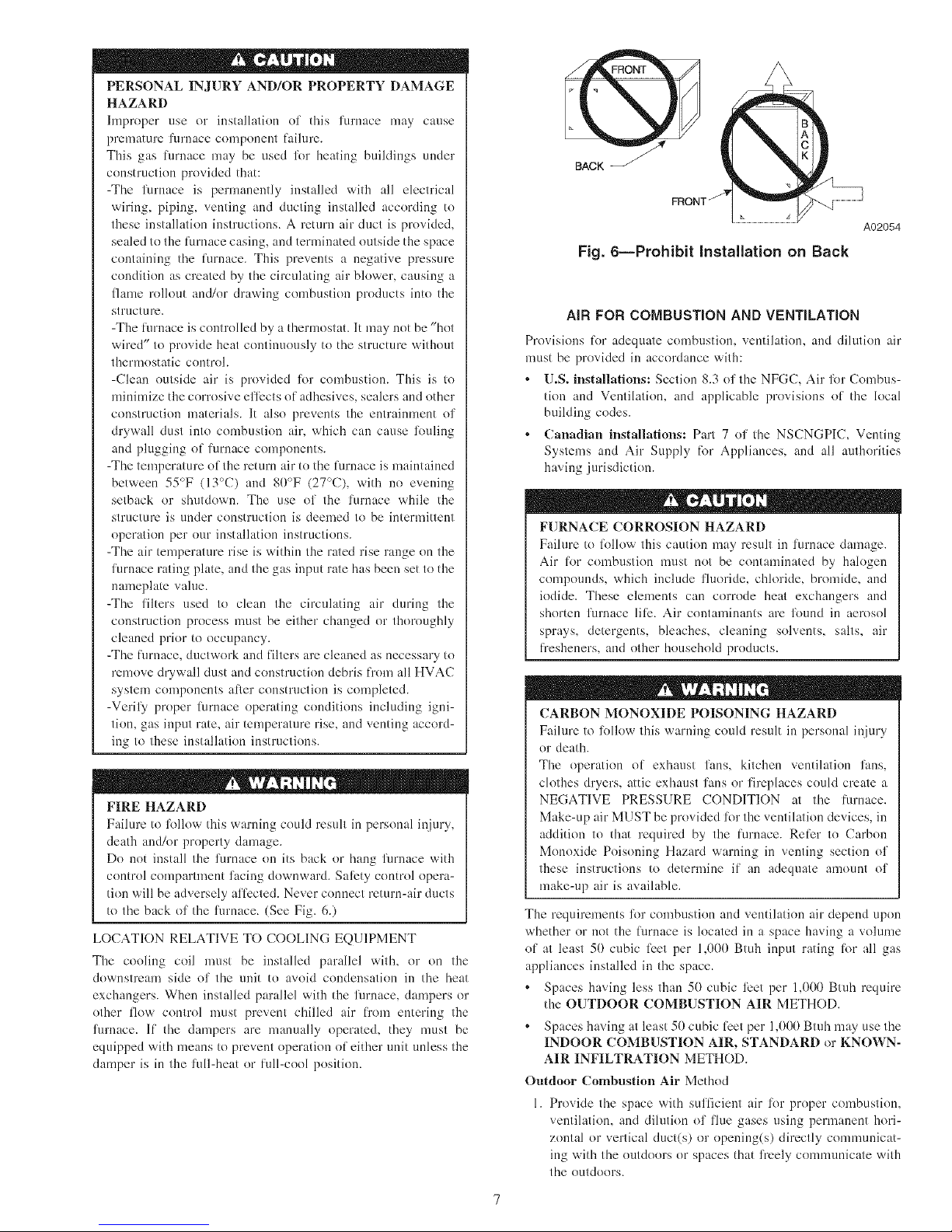
Do not install the furnace on its back or hang furnace with
control compartment facing downward. Sali_ty control opera-
tion will be adversely afli:cted. Never connect return-air ducts
to the back of the furnace. (See Fig. 6.)
LOCATION RELATIVE TO COOLING EQUIPMENT
The cooling coil n]ust be installed parallel with, or on the
downstream side of the unit to avoid condensation in the heat
exchangers. When installed parallel with the furnace, dampers or
other flow control n]ust prevent chilled air li"om entering the
furnace. If the dampers are manually operate& they must be
equipped with means to prevent operation of either unit unless the
damper is in the full-heat or lull-cool position.
BACK
A02054
Fig. 6--Prohibit Installation on Back
AIR FOR COMBUSTION AND VENTILATION
Provisions lot adequate combustion, ventilation, and dilution air
nmst be provided in accordance with:
U.S. installations: Section 8.3 of the NFGC, Air %r Combus-
tion and Ventilation, and applicable provisions of the local
building codes.
Canadian installations: Part 7 of the NSCNGPIC, Venting
Systems and Air Supply lbr Appliances, and all authorities
having jurisdiction.
FURNACE CORROSION HAZARD
Faihn'e to lbllow this caution may result in furnace damage.
Air [or combustion nn]st not be contaminated by halogen
compounds_ which inch]de fluoride, chloride, bromide_ and
iodide. These elements can corl:ode heat exchangers and
shorten furnace lili:. Air contaminants are flmnd in aerosol
sprays, detergents, bleaches, cleaning solvents, salts, air
li"esheners, and other household products.
CARBON MONOXIDE POISONING HAZARD
Faih]re to follow this warning could result in personal injury
or death.
The operation of exhaust fans, kitchen ventilation fans,
clothes dryers, attic exhaust fans or fireplaces could create a
NEGATIVE PRESSURE CONDITION at the li;rnace.
Make-up air MUST be provided li)r the ventilation devices, in
addition to that required by the fln'nace. Reli:r to Carbon
Monoxide Poisoning Hazard warning in venting section of
these instructions to determine if an adequate amount of
make-up air is available.
The requirements %r combustion and ventilation air depend upon
whether or not the lurnace is located in a space having a volume
of at least 50 cubic licet per 1,000 Btuh input rating lbr all gas
appliances installed in the space.
Spaces having less than 50 cubic li_et per 1,000 Btnh require
the OUTDOOR COMBUSTION AIR METHOD.
Spaces having at least 50 cubic li_etper 1,000 Btuh may use the
INDOOR COMBUSTION AIR, STANDARD or KNOWN-
AIR INFILTRATION METHOD.
Outdoor Combustion Air Method
1. Provide the space with sufficient air %r proper combustion,
ventilation, and dilution of flue gases using permanent hori-
zontal or vertical duct(s) or opening(s) directly comnmnicat-
ins with the outdoors or spaces that freely commmficate with
the outdoors.

Table 2-Minimum Free Area Required for Each Combustion Air Opening or Duct to Outdoors
TWO HORIZONTAL DUCTS SINGLE DUCT OR OPENING TWO OPENINGS OR VERTICAL DUCTS
FURNACE (1 SQ. IN./2,000 BTUH) (1,100 SQ. IvIM/KW) (1 SQ. IN./3,000 BTUH) (734 SQ. MM/KW) (1 SQ. IN./4,000 BTUH) (550 SQ. IvIM/KW)
iNPUT Free Area 01 Free Area 01 Free Area of
(BTUH) Opening and Duct Round Duct Opening and Duct Round Duct Opening and Duct Round Duct
(Sq. In.) (in. Dia) (sq In.) (in. Dia) (Sq In.) (In. Dia)
44,000 22 6 14.7 5 11 4
66,000 33 7 22 6 16.5 5
88,000 44 8 29.3 7 22 6
110,000 55 9 36.7 7 27.5 6
132,000 66 10 44 8 33 7
154,000 77 10 51.3 9 38.5 8
EXAMPLES: Determining Free Area
FURNACE WATER HEATER TOTAL INPUT
110,000 + 30,000 (140,000 divided by 4,000) 35.0 Sq. In. for each two Vertical Ducts or Openings
66,000 + 40,000 (106,000 divided by 3,000) 35.3 Sq. In. for a Single Duct or Opening
88,000 + 30,000 (118,000 divided by 2,000) 59.0 Sq. In. for each of two Horizontal Ducts
Table 3-Minimum Space Volumes for 100% Combustion, Ventilation, and
Dilution from Indoors
OTHER THAN FAN=ASSiSTED TOTAL FAN-ASSISTED TOTAL
{1,000'S BTUR GAS iNPUT RATE) (1,000'S BTUR GAS iNPUT RATE)
ACH
30 I 40 ! 50 44 ! 66 I 88 I 110 ! 132 I 154
Space Volume (ft3)
0.60 1,050 1,400 1,750 1,100 1,650 2,200 2,750 3,300 3,850
0.50 1,260 1,680 2,100 1,320 1,980 2,640 3,300 3,960 4,620
0.40 1,575 2,100 2,625 1,650 2,475 3,300 4,125 4,950 5,775
0.30 2,100 2,800 3,500 2,200 3,300 4,400 5,500 6,600 7,700
0.20 3,150 4,200 5,250 3,300 4,950 6,600 8,250 9,900 11,550
0.10 6,300 8,400 10,500 6,600 9,900 13,200 16,500 19,800 23,100
0.00 NP NP NP NP NP NP NP NP NP
NP = Not Permitted
2. Fig. 7 illustrates how to provide TWO OUTDOOR OPEN-
INGS, one inlet and one outlet combustion and ventilation air
opening, to the outdoors.
a. One opening MUST commence within 12" (300 ram) of
the ceiling and the second opening MUST colnmence
within 12" (300 rain) of the floor.
b. Size openings and ducts per Fig. 7 and Table 2.
c. TWO HORIZONTAL DUCTS require 1 square inch of
free area per 2,000 Btuh (l,lO0 nnn2/kW) of cembined
input R)r all gas appliances in the space per Fig. 7 and Table
2.
d. TWO OPENINGS OR VERTICAL DUCTS require 1
square inch ol free area per 4,000 Btuh (. 50 mm-/l<W) l_r
combined input of all gas appliances in the space per Fig.
7 and Table 2.
3. ONE OUTDOOR OPENING requires:
a. 1 square inch of free area per 3,000 Bmh (734 elnl2/kW)
liar combined input of all gas appliances in the space per
Table 2 and
b. Not less than the sum of the areas ef all vent connectors in
the space.
The opening shall commence within 12" (300 nnn) of the ceiling.
Appliances in the space shall have clearances of at least l" (25
ram) l_'om the sides and back and 6" (150 nnn) from the l_'ont. The
opening shall directly comnmnicate with the outdoors or shall
communicate thamgh a vertical or horizontal duct to the outdoors
er spaces (crawl or attic) that l]'eely conmmnicate with the
eutdoors.
Indoor Combustion Air{) NFPA & AGA
Standard and Known-Air-Infiltration Rate Methods
Indoor air is permitted R)r combustion, ventilatiom and dilution,
if the Standard or Known-Air-Infiltratlon Method is used.
CARBON MONOXIDE POISONING HAZARD
Failure to lollow this warning could result
in death and/or personal injury.
Many homes require air to be supplied l]'om outdoors lk_r
furnace combustion, ventilation, and dilution of flue gases.
The furnace combustion air supply must be provided in
accordance with this instruction manual.
The Standard Method:
1. The space has no less vohnne than 50 cubic IL'et per l,I)I)I)
Btuh of the maxinmm input ratings lk)r all gas appliances
installed in the space and
2. The air infiltration rate is not known to be less than 0.40 air
changes per hour (ACH).

12"MAX
1SQIN. A
PER 2000
T
BTUH*
[
DUCTS
TO
OUTDOORS
i SQIN.
PER 2000
BTUH* f
CIRCULATING AIR DUCTS
I, ii 12"MAX
DL_C_T_"-- 1SQIN.
TO PER 4000
OUTDOORS BTUH*
*Minimum dimensions of 3 in.
NOTE: Use any of the following
combinations of openings:
A&B C&D D&E F&G
A03174
Fig. 7--Air for Combustion, Ventilation, and
Dilution for Outdoors
The Known Air Infiltration Rate Method shall be used, if the
irffiltration rate is known to be:
1. Less than 0.40 ACH and
2. Equal to or greater than 0.10 ACH
Infiltration rates greater dnm 0.60 ACH shall not be used. The
nfinimum required volume of tile space varies with the number of
ACH and shall be detemfined per Table 3 or Equations 1 and 2.
Determine tile minimum required volume %r each appliance in the
space and add the vohnnes together to get the total udnimum
required vohnne %r the space.
Tahle 3-Mininmm Space Volumes were determined by using the
fl}llowing equations fi'nm the National Fuel Gas Code ANSI
Z223.1-2002/NFPA .54-2002,8.3.2.2:
1. For other than fan-asslsted appliances, such as a drali
hood-equipped water heater:
-21ft3_ Iother ._
Volume Oth,_--A---"C-Hp0-0 B'iu/hFJ
A04002
2. For fan-assisted appliances such as this furnace:
-- 1S_t 3 I fan
A04003
CIRCULATING AIR ]_l
DUCTS
I I I I I I
I I I I I I
I I I I I I
INTERIOR
HEATED
SPACE
l
IRCULATING AIR DUCTS
VENT THROUGH ROOF
_< 12" AX
U-z -=--1SQ IN.
PER1000
TUH*,NDOOR
OR WALL
UNCONFINED
! SPACE
6" MIN
(FRONT)t
z_ 1SQIN.
<Lu PER 1000
rr a_ BTUH* IN DOOR
<O __--ORWALL
iii
©
L12" MAX
* Minimum opening size is 100 sq in. with
minimum dimensions of 3 in.
tMinimum of 3 in. when type-B1 vent is used.
A03175
Fig. 8--Air for Combustion, Ventilation, and
Dilution from Indoors
l[:
lo,,.. , = combined input ol' all other than fan-assisted appli-
ances in Btu/hr
lh, , = combined input of all fan-assisted appliances in Btu/hr
ACH = air changes per hour (ACH shall not exceed 0.60.)
The %llowing requirements apply to the Standard Method and to
the Known Air Infiltration Rate Method.
I. Adjoining rooms can be considered part of a space if:
a. There are no closable doors between l'ooms.
b. Combining spaces on same floor level. Each opening shall
have fi'ee area of at least 1 in.2/l,000 Btuh (2,000 mme/kW)
of the total input rating of all gas appliances ilk the space,
but net less than 100 in. 2 (0.06 m2). One opening shall
connnence within 12" (300 ram) of the ceiling and the
second opening shall commence within 12" (300 ram) of
the floor. The mininmm dimension of air openings shall be
at least 3 in. (80 ram). (See Fig. 8.)
c. Combining space on dilli:rent floor levels. The volumes of
spaces on difii:rent floor levels shall be considered as
communicating spaces if connected by one or more perma-
nent openings ilk deers or floors having l)'ee area of at least
2 in.2/l,000 Btah (4,400 mm2/kW) of total input rating of
all gas appliances.
2. An attic or crawlspace may be considered a space that freely
communicates with the outdoors provided there are adequate
permanent ventilation openings directly to outdoors having

BO]qOM FILLER
PANEL
BOTTOM CLOSURE
PANEL
A02098
Fig. 9--Removing Bottom Closure Panel
fi'ee area of at least l-in.2/4,000 Btuh of total input rating lot
all gas appliances in the space.
3. In spaces that use the Indoor Combustion Air Method,
infiltration should be adequate to provide air lor combustion,
permanent ventilation and dilntion of title gases. However, in
buildings with unusually tight constrnctiom additional air
MUST be provided using the methods described in the
Outdoor Combustion Air Method section.
Unusually tight construction is defined as
Construction with:
a. Walls and ceilings exposed to the outdoors have a continu-
ous, sealed vapor barrier. Openings are gasketed or sealed
and
b. Doors and openable windows are weatherstripped and
c. Other openings are caulked or sealed. These include joints
around window and door fi'ames, between sole plates and
floors, between wall-ceiling joints, between wall panels, at
penetrations lor plumbing, electrical and gas lines, etc.
Combination of Indoor and Outdoor Air
1. Indoor openings shall comply with the Indoor Combustion
Air Method below and,
2. Outdoor openings shall be located as required in the Outdoor
Comlmstlon Air Method mentioned previously and,
3. Outdoor openings shall be sized as lollows:
a. Calculate the Ratio of all Indoor Space volume divided by
required volume lot Indoor Combustion Air Method
below.
b. Outdoor opening size reduction Factor is 1 minus the
Ratio in a. above.
c. Minimum size of Outdoor openings shall be the size
required in Outdoor Combustion Air Method above
multiplied by reduction Factor in b. above. The ndnimum
dimension of air openings shall be not less than 3 in. (80
mm).
INSTALLATION
UPFLOW INSTALLATION
Bottom Return Air Inlet
These lurnaces are shipped with bottom closure panel installed in
bottom return-air opening. Remove and discard this panel when
bottom return air is used. To remove bottom closure panel,
perlorm the lollowing:
1. Tilt or raise furnace and remove 2 screws holding bottom filler
panel. (See Fig. 9.)
2. Rotate bottom filler panel downward to release holding tabs.
Fig. 10--Leveling Legs
A89014
10
3. Remove bottom closure panel.
4. Reinstall bottom filler panel and screws.
Side Return Air Inlet
These furnaces are shipped with bottom closure panel installed in
bottom return-air opening. This panel MUST be in place when
only side return air is used.
NOTE: Side return-air openings can be used in UPFLOW and
most HORIZONTAL configurations. Do not use side return-air
openings in DOWNFLOW configuration.
Leveling Legs (If Desired)
In upflow position with side return inlet(s), leveling legs may be
used. (See Fig. 111.) Install field-supplied, 5/16 X l-l/2 in. (max)
corrosion-resistant machine bolts, washers and nuts.
NOTE: Bottom closure must be used when leveling legs are used.
It may be necessary to remove and reinstall bottom closure panel
to install leveling legs. To remove bottom closure panel, see Item
1. in Bottom Return Air Inlet section.
To install leveling legs:
1. Position furnace on its back. Locate and drill a hole in each
bottom corner of furnace. (See Fig. 10.)
2. For each leg, install nut on bolt and then install bolt and nut in
bole. (Install flat washer if desired.)
3. Install another nut on other side of fiwnace base. (Install flat
washer if desired.)
4. Adjust outside nut to provide desired height, and tighten inside
nut to secure arrangement.
5. Reinstall bottom closure panel if removed.
DOWNFLOW INSTALLATION
NOTE: For downflow applications, this fllrnace is approved lor
use on combustible flooring when any one of the fl}llowing 3
accessories are used:
* Special Base, KGASB
* Cased Coil Assembly Part No. CD5 or CK5
° Coil Box Part No. KCAKC
1. Determine application being installed from Table 3.
2. Construct hole in floor per Table 3 and Fig. 11.
3. Construct plenum to dimensions speci/Sed in Table 3 and Fig.
11.

FURNACE
(OR COIL CASING
WHEN USED)
COMBUSTIBLE
FLOORING
SUBBASE
PLENUM
__ FLOOR __
OPENING
• . A96283
Fig. 11iFloor and Plenum Opening Dimensions
Fig. 12iFurnace, Plenum, and Subbase Installed on
a Combustible Floor A96285
FURNACE
CD5 OR CK5
COIL ASSEMBLY
OR KCAKC
COIL BOX
COMBUSTIBLE
FLOORING
SHEET METAL____=._
PLENUM
__ FLOOR
OPENING
A04140
Fig. 13--Furnace, Plenum, and Coil Assembly or Coil
Box Installed on a Combustible Floor
A04140
4. If downflow subbase, KGASB is used, install as shown in Fig.
12. If Coil Assembly Part No. CD5 or CK5 or Coil Box Part
No. KCAKC is used, install as shown in Fig. 13.
NOTE: It is recommended that the perlbrated supply-air duct
flanges be completely fblded over or removed li"om furnace when
installing the fimlace on a factory-supplied cased coil or coil box.
To remove the supply-air duct flange, use wide duct pliers or hand
seamers to bend flange back and lbrth until it breaks off. Be careful
of sharp edges. (See Fig. 14.)
II
Bottom Return Air Inlet
These furnaces are shipped with bottom closure panel installed in
bottom return-air opening. Remove and discard this panel when
bottom return air is used. To remove bottom closure panel,
perlbrm the lollowiug:
1. Tilt or raise furnace and remove 2 screws holding bottom filler
panel. (See Fig. 9.)
2. Rotate bottom filler panel downward to release holding tabs.
3. Remove bottom closure panel.

FURNACE
CASING
WIDTH
TaNe 4--Opening Dimensions 0n.)
APPLICATION
C
Upflow Applications on Combustible or Noncombustible
Flooring (KGASB subbase not required) 13-5/16
Downflow Applications on Noncombustible Flooring 13-3/16
(KGASB subbase not required)
14-3/16 Downflow applications on combustible flooring (KGASB 13-7/16
subbase required)
Downflow Applications on Combustible Flooring with CD5 or
CK5 Coil Assembly or KCAKC coil box (KGASB subbase 13-5/16
not required)
Upflow Applications on Combustible or Noncombustible 16-5/8
Flooring (KGASB subbase not required)
Downflow Applications on Noncombustible Flooring 16-1/2
(KGASB subbase not required)
17-1/2 Downflow applications on combustible flooring (KGASB 16-3/4
subbase required)
Downflow Applications on Combustible Flooring with CD5 or
CK5 Coil Assembly or KCAKC coil box (KGASB subbase 16-1/2
not required)
Upflow Applications on Combustible or Noncombustible 20-1/8
Flooring (KGASB subbase not required)
Downflow Applications on Noncombustible Flooring 20
(KGASB subbase not required)
21 Downflow applications on combustible flooring (KGASB 20-1/4
subbase required)
Downflow Applications on Combustible Flooring with CD5 or
CK5 Coil Assembly or KCAKC coil box (KGASB subbase 20
not required)
Upflow Applications on Combustible or Noncombustible 23-5/8
Flooring (KGASB subbase not required)
Downflow Applications on Noncombustible Flooring 23-1/2
(KGASB subbase not required)
24-1/2 Downflow applications on Combustible flooring (KGASB 23-3/4
subbase required)
Downflow Applications on Combustible Flooring with CD5 or
CK5 Coil Assembly or KCAKC coil box (KGASB subbase 23-1/2
not required)
PLENUM OPENING
A B
12-11/16 21-5/8
12-9/16 19
11-13/16 19
12-5/16 19
16 21-5/8
15-7/8 19
15-1/8 19
15-1/2 19
19-1/2 21-5/8
19-3/8 19
18-5/8 19
19 19
23 21-1/8
22-7/8 19
22-1/8 19
22-1/2 19
FLOOR OPENING
D
22-1/4
19-5/8
20-5/8
2O
22-1/4
19-5/8
20-5/8
20
22-1/4
19-5/8
20-5/8
20
22-1/4
19-5/8
20-5/8
20
4. Reinstall bottom filler panel and screws.
HORIZONTAL INSTALLATION
FIRE, EXPLOSION, AND CARBON MONOXIDE
POISONING HAZARD
Failure to lk)llow this walTning could result in personal injury,
death, and/or property damage.
Do not install the furnace on its back or hang lklrnace with
control compamnent facing downward. Sali:ty control opera-
tion will be adversely al_i:cted. Never connect return-air ducts
to the back of the furnace.
The lurnace can be installed horizontally in an attic or crawl space
on either the leli-hand (LH) or right-hand (RH) side. The furnace
can be hung l)'om floor joists, rafters or trusses or installed on a
non-combustible platlkwm, blocks, bricks or pad.
Suspended Furnace Support
The furnace may be supported under each end with threaded rod,
angle iron or metal plumber's strap as shown. (See Fig. 15 and 16.)
Secure angle iron to bottom of furnace as shown. Heavy-gauge
sheet metal straps (plumber's straps) may be used to suspend the
lhrnace li"om each bottom corner. To prevent screws li"om pulling
12
out, use 2 #8 x 3A-in. screws into the side and 2 #8 x 3A-in. screws
in the bottom of the lurnace casing lkw each strap. (See Fig. 15 and
16.)
If the screws arc attached to ONLY the lklrnace sides and not the
bottom, the straps nmst be vertical against the furnace sides and
not pull away fi'om the furnace sides, so thai the strap attachment
screws arc not in tension (are loaded in shear) liar reliable support.
Platliwm Furnace Support
Construct working platform at location where all rcqnired furnace
clearances are met. (See Fig. 2 and 17.) For furnaces with l-in.
clearance requirement on side, set furnace on noncombustible
blocks, bricks or angle iron. For crawl space installations_ if the
furnace is not suspended li"om the floor joists, the ground under-
neath lilrnace mnst be level and the furnace set on blocks or bricks.
Roll-Out Protection
Provide a ndnimum 17-3/4" X 22" piece of sheet metal 1()1"flame
roll-out protection in li"ont of burner area lot lilrllaces closer than
12 inches above the combustible deck or suspended furnaces
closer than 12 inches to joists. The sheet metal MUST extend
underneath the limnace casing by 1 in. with the door removed.
The bottom closure panel on furnaces of widths 17-1/2 in. and
larger may be used liw flame roll-out protection when bottom of
furnace is used li_r return air connection. See Fig. 17 liw proper
orientation of roll-out shield.

PREFERRED
DOW NFLOW
PREFERRED
HORIZONTAL
PREFERRED
\
120_
MIN
I.
PREFERRED
120_
MIN
PREFERRED
PERMITTED PERMITTED PERMITTED
Fig. 14--Duct Flanges
A02329
Bottom Return Air Inlet
These lurnaces are shipped with bottom closure panel installed in
bottom return-air opening. Remove and discard this panel when
bott()m return air is used. To remove bottom closurc panel,
perli_rm the fl}llowing:
1. Tilt or raise lurnace and remove 2 screws holding bottom filler
panel. (See Fig. 9.)
2. Rotate bottom filler panel downward to release holding tabs.
3. Remove bottom c]osnrc panel.
4. Reinstall bottom filler panel and screws.
Side Return Air Inlet
These furnaces are shipped with bottom closure panel installed in
bottom return-air opening. This panel MUST be in place when side
return air inlet(s) is used without a bottom return air inlet.
Not all horizontal furnaces are approved lk_r side return air
connections. (See Fig. 20.)
FILTER ARRANGEMENT
CARBON MONOXIDE AND POISONING
HAZARD
Failure to fi)llow this warning could result in personal in.jury,
or death.
Never operaIe a lurnace without a filter or with filter access
door removed.
There are no provisions lot an internal filter rack in these furnaces.
Deluxe furnaces are shipped with a factory supplied Media Filter
Cabinet. The Media Filter Cabinet uses either the factory-supplied
standard l-in. l]lter or a 4 in. wide Media Filter which can be
purchased separately.
Relier to the instructions supplied with Media Cabinet fl_r assembly
and installation options.
AIR DUCTS
General Requirements
The duct system should be designed and sized according to
accepted national standards such as those published by: Air
Conditioning Contractors Association (ACCA), Sheet Metal and
Air Conditioning Contractors National Association (SMACNA) or
American Society of Hearing, RefYigerating and Air Conditioning
Engineers (ASHRAE) or consult The Air ,5).'stenz.sDe.sign G,id_,-
lines rclierence tables available li"om your local distributor. The
duct system should be sized to handle the required system design
CFM at the design external static pressure. The furnace airflow
rates are provided in Table 5-AIR DELIVERY-CFM (With Filter).
When a lk_rnace is installed so that the supply ducts carry air
circulated by the lin'nace to areas outside the space containing the
furnace, the return air shall also be handled by duct(s) sealed to the
furnace casing and terminating outside the space containing the
furnace.
Secure ductwork with proper lasteners lot type of ductwork used.
Seal supply- and return-duct connections to furnace with code
approved tape or duct sealer.
NOTE: Flexible connections should be used between ductwork
and lkn'nace to prevent transmission of vibration. Ductwork pass-
ing through unconditioned space should be insulated and sealed to
enhance system perlbrmance. When air conditioning is used, a
vapor barrier is recommended.
Maintain a 1-in. clearance fi'om combustible materials to supply air
ductwork lot adistance of 36 in. horizontally from the lurnace. See
NFPA 9(tB or local code fl}r further requirements.
Ductwork Acoustical Treatment
NOTE: Metal duct systems that do not have a 90 degree elbow
and lit fl of main duct to the first branch take-off may require
internal acoustical lining. As an alternative, fibrous ductwork may
be used if constructed and installed in accordance with the latest
edition of SMACNA construclion standard on fibrous glass ducts.
Both acoustical lining and fibrous ductwork shall comply with
NFPA 9(tB as tested by UL Standard 181 lor Class 1 Rigid air
ducts.
Supply Air Connections
For a furnace not equipped with a cooling coil, the outlet duct shall
be provided with a removable access panel. This opening shall be
accessible when the limlace is installed and shall be of such a size
that the heat exchanger can be viewed lot possible openings using
light assistance or a probe can be inserted lor sampling the air
stream. The cover attachment shall prevent leaks.
13

I
I
I
I
I
V4" THREADED ROD
4 REQ.
J
UTER DOOR
&SSEMBLY
8" MIN FOR DOOR
REMOVAL
¢
SECURE ANGLE
IRON TO BOTTOM
OF FURNACE WITH
3 #8 x 3/4"SCREWS
TYPICAL FOR 2 SUPPORTS
1" SQUARE, 1V4" x 1V4"x %" ANGLE IRON
OR UNI-STRUT MAY BE USED
(2) HEX NUTS, (2) WASHERS & (2) LOCK WASHERS
REQ. PER ROD
A05027
Fig. 15--Horizontal Unit Suspension
[Jpflow and Horizontal Furnaces
Connect supply-air duct to flanges on furnace supply-air outlet.
Bend flange upward to 90° with wide duct pliers. (See Fig. 14.)
The supply-air duct must be connected to ONLY the furnace
supply-outlet-air duct flanges or air conditioning coil easing (when
used). DO NOT cut main furnace casing side to attach supply air
duct, humidifier, or other accessories. All accessories MUST be
connected to duct external to l_lrnaee main casing.
NOTE: For horizontal applications, the top-most flange may be
bent past 90 degrees to allow the evaporator coil to hang on the
flange temporarily while the remaining attachment and sealing of
the coil are perlormed.
Downflow Furnaces
Connect supply-air duct to supply-air outlet on limmce. Bend
flange inward past 90 ° with wide duct pliers. (See Fig. 14.) The
supply-air duet nmst be connected to ONLY the limmce supply-
outlet or air conditioning coil casing (when used). When installed
on combustible material, supply-air duct must be connected to
ONLY the accessory subbase KGASB0201ALL or a factory
approved air conditioning coil casing. DO NOT cut main furnace
casing to attach supply side air duct, humidifier, or other accesso-
ries. All accessories MUST be connected to duct external to
lhrnace casing.
Return Air Connections
FIRE HAZARD
Failure to lk_llow this warning could cause personal injury
death andk_r property damage.
Never connect return-air duets to the back of the furnace.
Follow instructions below.
Downflow Furnaces
The return-air duct nmst be connected to return-air opening
(bottom inlet) as shown in Fig. 19. DO NOT cut into easing sides
(left or right). Side opening is permitted lbr only upflow and most
horizontal furnaces. (See Fig. 19.) Bypass humidifier connections
should be made at ductwork or coil casing sides exterior to
furnace.
Upflow and Horizontal Furnaces
The return-air duct nmst be connected to bottom, sides (left or
right), or a combination of bottom and side(s) of main furnace
casing as shown in Fig. 18 and 20. Bypass humidifier may be
attached into tmused return air side of the furnace casing. (See Fig.
18 and 20.)
Not all horizontal furnaces are approved %r side return air
connections. (See Fig. 20.)
14

OUTER DOOR
ASSEMB_ X
II
II
I1
I!
!1
22 GAUGE GALVANIZED
FOR 4 STRAPS
AIR
BACK QP
FURNACE
METHOD 1
FOLD ALL STRAPS UNDER
FURNACE AND SECURE WTH
(4) #8 x 3/4 SHEET METAL SCREWS
(2 SCREWS IN SIDE AND 2 SCREWS
IN BOTTOM).
METHOD 2
USE (4) #8 x 3/4 SHEET
METAL SCREWS FOR EACH
STRAR THE STRAPS
SHOULD BE VERTICAL
AGAINST THE FURNACE
SIDES AND NOT PULL AWAY
FROM THE FURNACE
SIDES.
Fig. 16--Horizontal Suspension with Straps
LINE CONTACT ONLY PERMISSIBLE BETWEEN
LINES FORMED BY INTERSECTIONS OF
THE TOP AND TWO SIDES OF THE FURNACE
JACKET AND BUILDING JOISTS,
STUDS, OR FRAMING.
17 3/4" OVER ALL
4 3/4" UNDER DOOR
1" UNDER FURNACE
EXTEND OUT 12" OUT
FROM FACE OF DOOR
A03176
30-IN. MIN
* WHEN USED WITH
SINGLE WALL VENT
CONNECTIONS
EQUIPMENT
SHUT-OFF GAS VALVE
SEDIMEN] UNION
TRAP
Fig. 17--Typical Attic Installation
A03177
15

Table 5--Air Delivery - CFM (With Filter)*
FURNACE
SIZE
024045
036045
024070
036070
048070
042090
048090
060090
036110
048110
066110
RETURN-AIR
INLET
Bottom
or
Side(s)
Bottom
or
Side(s)
Bottom
or
Side(s)
Bottom
or
Side(s)
Bottom
or
Side(s)
Bottom
or
Side(s)
Bottom
or
Side(s)
Bottom
Only
Both Sides or
1 Side & Bottom
1 Side Only
Bottom
or
Side(s)
Bottom
or
Side(s)
Bottom
Only
Bottom Sides or
1 Side & Bottom
1 Side Only
EXTERNAL STATIC PRESSURE (IN,
SPEED
0.1 0.2 0.3 0.4 0.5 0.6
High 1085 1035 975 915 845 770
Med-High 920 875 830 770 710 840
Med-Low 820 775 730 680 620 555
High 1440 1375 1305 1240 1160 1070
Med-High 1360 1300 1240 1175 1115 1040
Med-Low 1250 1210 1160 1100 1040 985
Low 1085 1055 1035 990 945 885
High 1030 1010 980 945 900 845
Med-High 835 815 790 780 720 675
Med-Low 725 700 875 645 800 555
High 1425 1375 1320 1265 1200 1125
Med-High 1320 1280 1240 1205 1140 1075
Med-Low 120 1175 1145 1105 1050 990
Low 1040 1030 1010 985 945 895
High 1808 1740 1670 1600 1530 1445
Med-High 1630 1585 1530 1470 1405 1330
Med-Low 1460 1420 1385 1325 1280 1220
Low 1275 1250 1225 1195 1155 1105
High 1650 1600 1535 1465 1385 1285
Med-High 1515 1485 1440 1380 1300 1220
Med-Low 1385 1360 1320 1260 1195 1120
Low 1205 1180 1160 1120 1085 1005
High 2060 1985 1915 1820 1720 1610
Med-High 1790 1765 1715 1645 1560 1470
Med-Low 1505 1505 1480 1440 1375 1300
Low 1225 1225 1220 1195 1155 1085
High 2405 2310 2220 2130 2025 1920
Med-High 2225 2155 2080 1995 1895 1785
Med-Low 2020 1955 1880 1805 1730 1630
Low 1810 1765 1715 1645 1565 1480
High 2530 2450 2385 2270 2185 2065
Med-High 2285 2215 2150 2075 1985 1890
Med-Low 1995 1945 1900 1840 1770 1685
Low 1770 1740 1700 1645 1575 1505
High 2475 2395 2300 2200 2090 1985
Med-High 2260 2190 2110 2035 1940 1845
Med-Low 1950 1910 1855 1795 1730 1650
Low 1730 1695 1650 1600 1535 1470
High 1625 1575 1515 1445 1355 1260
Med-High 1510 1470 1415 1355 1285 1185
Med-Low 1360 1335 1295 1250 1180 1100
Low 1195 1180 1155 1115 1085 980
High 2035 1965 1880 1790 1680 1495
Med-High 1745 1710 1650 1560 1450 1340
Med-Low 1530 1515 1470 1400 1310 1215
Low 1270 1265 1235 1195 1130 1055
High 2530 2470 2400 2320 2220 2115
Med-High 2230 2205 2165 2110 2035 1950
Med-Low 1920 1900 1880 1845 1795 1730
Low 1640 1650 1635 1610 1575 1520
High .... 2415 2350 2250 2145
Med-High 2235 2200 2155 2100 2040 1955
High 2540 2495 2430 2355 2285 2175
Med-High 2125 2120 2105 2060 2010 1940
*A filter is required for each return-air inlet. Airflow performance included 1-in. washable filter media such as contained
determine airflow performance without this filter, assume an additional 0.1 in. wc available external static pressure.
-- Indicates unstable operating conditions.
wc)
0.7 0.8 0.9 1.0
675 565 390 195
555 440 250 --
470 380 190 --
975 870 730 580
950 850 725 575
885 790 870 520
810 715 595 435
775 680 490 335
610 490 375 265
475 390 300 --
1035 940 830 655
995 905 790 620
920 840 725 555
845 765 655 505
1360 1280 1180 1075
1255 1170 1080 990
1155 1080 995 910
1050 980 910 835
1175 1055 895 645
1115 990 830 600
1025 915 710 565
925 810 830 510
1490 1340 1135 925
1345 1195 1010 820
1190 1045 890 740
985 870 735 620
1790 1860 1530 1350
1675 1565 1420 1260
1535 1420 1275 1135
1390 1280 1145 1005
1940 1805 1670 1505
1780 1860 1525 1360
1600 1480 1350 1180
1415 1325 1190 1040
1865 1730 1585 1425
1735 1820 1475 1325
1555 1445 1310 1150
1385 1285 1165 1000
1165 990 785 595
1070 890 725 530
985 810 670 475
860 740 805 410
1365 1215 1075 875
1205 1090 955 750
1095 990 830 670
970 875 720 600
2000 1865 1730 1590
1855 1740 1615 1485
1650 1555 1460 1340
1455 1375 1285 1170
2015 1875 1715 1560
1850 1740 1595 1470
2065 1935 1785 1650
1840 1730 1615 1485
in factory-authorized accessory filter rack. To
16

Table 5--Air Delivery - CFM (With Filter)* (Continued)
FURNACE
SIZE
048135
066135
060155
RETURN-AIR
iNLET
Bottom
or
Side(s)
Bottom
Only
Bottom, Sides or
1 Side & Bottom
1 Side Only
Bottom
Only
Both Sides Or
1 Side & Bottom
1 Side Only
SPEED
EXTERNAL STATIC PRESSURE (IN, we)
0.1 0.2 0.3 0.4 0.8 0.8 0.7 0.8 0.9 1.0
High 2090 2010 1930 1835 1710 1590 1470 1335 1025 835
Med-High 1790 1755 1705 1640 1550 1465 1360 1210 945 785
Med-Low 1545 1525 1500 1450 1380 1315 1215 1005 855 670
Low 1325 1320 1295 1285 1210 1150 995 865 745 540
High 2485 2400 2310 2215 2110 2000 1880 1725 1535 1355
Med-High 2195 2150 2090 2000 1920 1825 1720 1565 1405 1255
Med-Low 1880 1850 1820 1780 1715 1835 1540 1415 1290 1160
Low 1640 1635 1615 1585 1530 1465 1370 1255 1150 1040
High .... 2385 2305 2195 2085 1960 1825 1670 1465
Med-High 2180 2145 2060 2010 1945 1865 1765 1660 1515 1325
High .... 2245 2155 2055 1940 1825 1695 1555 1385
Med-High 2135 2085 2035 1975 1895 1795 1685 1565 1445 1265
High 2465 2430 2375 2305 2230 2110 2000 1865 1725 1545
Med-High 2115 2105 2075 2030 1980 1910 1830 1725 1590 1425
Med-Low 1800 1790 1770 1735 1695 1640 1570 1465 1345 1225
Low 1570 1565 1550 1525 1495 1445 1370 1270 1175 1070
High .... 2375 2285 2200 2105 1995 1870 1730 1570
Med-High 2155 2135 2095 2040 1975 1895 1790 1685 1550 1400
High .... 2260 2180 2085 1975 1865 1740 1605 1455
Med-High 2140 2095 2040 1975 1890 1810 1705 1595 1480 1325
*A filter is required for each return-air inlet. Airflow performance included 1-in. washable filter media such as contained in factory-authorized accessory filter rack. To
determine airflow performance without this filter, assume an additional 0.1 in. wc available external static pressure.
Indicates unstable operating conditions.
GAS PIPING
t , =
FIRE OR EXPLOSION HAZARD
Failure to Iollow this warning could result in personal injury,
death, and/or property damage.
Never purge a gas line into a combustion chamber. Never test
lbr gas leaks with an open flame. Use a commercially
available soap solution made specil]cally liar the detection of
leaks to check all connections.
FIRE OR EXPLOSION HAZARD
Failure to Iollow this warning coud result in personal injury,
death, andk_r property damage.
Use proper length of pipe to avoid stress on gas control
manili_dd and a gas leak.
Gas piping must be installed in accordance with national and local
codes. Rel;,:'rto current edition of NFGC in the U.S., the NSCNG-
P1C in Canada.
Installations must be made in accordance with all authorities
having jurisdiction. If possible, the gas supply line should be a
separate line running directly l)'om meter to lurnace.
NOTE: In the state of Massachusetts:
1. Gas supply connections MUST be perlormed by a licensed
plumber or gas fitter.
2. When flexible connectors are used, the maxiumm length
shall not exceed 36 inches (915 ram).
3. When lever handle type manual equipment shutoff valves am
used, they shall be T-handle valves.
4. The use of copper robing liar gas piping is NOT approved by
the state of Massachusetts.
Reli:r to Table 6 for recommended gas pipe sizing. Risers lnnst be
used to connect to furnace and to meter. Support all gas piping
with appropriate straps, hangers, etc. Use a minimum of 1 hanger
every 6fl. Joint compound (pipe dope) should be applied sparingly
and only to male threads of joints. Pipe dope must be resistant to
the action of propane gas.
17
FIRE OR EXPLOSION HAZARD
Failure to 12_llowdais warning could result in personal injury,
death, and/or property damage.
If local codes allow the use of a flexible gas appliance
connector, always use a new listed connector. Do not use a
connector which has previously served another gas appliance.
Black iron pipe shall be installed at the limlace gas control
valve and extend a minimnm of 2 in. outside the l_lrnace.
FURNACE OVERHEAT HAZARD
Failure to lollow this caution may result in property damage.
Connect gas pipe to gas valve using a backup wrench to avoid
damaging gas controls and burner misalignment.
An accessible manual equipment shutoff' valve MUST be installed
external to lilrnace casing and within 6 fl of furnace. A l/8-in. NPT
plugged tapping, accessible lkn"test gauge connection, MUST be
installed immediately upstream of gas supply connection to
furnace and downstream of manual equipment shutoff valve.
NOTI=: The furnace gas control valve inlet pressure tap connec-
tion is suitable to use as test gauge connection providing test
pressure DOES NOT exceed maximum 0.5 psig (14-in. we) stated
on gas control valve. (See Fig. 52.)
Some installations require gas entry on right side of furnace (as
viewed in upflow.) (See Fig. 21a.)
Install a sediment trap in riser leading to li_rnace as shown in Fig
21b. Connect a capped nipple into lower end of tee. Capped nipple
should extend below level of furnace gas controls. Place a ground
.joint union between furnace gas control valve and exterior manual
equipment gas shutoff valve. A l/8-in. NPT plugged tapping,
accessible liar test gauge connection, MUST be installed immedi-
ately upstream of gas supply connection to lurnace and down-
stream of manual equipment shutoff valve.

['_ UPFLOW RETURN AIR CONFIGURATIONS AND RESTRICTIONS
AIR FLOW MODELS RETURN AIR RETURN AmR RETURN AIR
CONNECTION t CONNECTION 2 CONNECTmON 3
ONLY ONLY ONLY
066.060, -22 AND YES YES YES
-20 MODELS
ALL OTHER MODELS YES YES YES YES
UP,LOW
HESTHIcrloNS
Fig. 18--Upflow Return Air Configurations and Restrictions
RETURN AIR
COMBINATmQNS
OF 1,2, AND3
YES
A02075
DOWNFLOWRETURNAIRCONF1GURATIONSANDRESTRICTIONS
_J _ t AIR FLOW MODELS RETURN AIR RETURN AIR
CONNECTION 1 CONNECTION 2
ONLY ONLY
066.060, -22 AND YES NO
-20 MODELS
ALL OTHER MODELS YES NO NO
suPPLY
AIR
RETURN AIR RETURN AIR
CONNECTION 3 COMBINATIONS
ONLY OF 1, 2, AND 3
NO NO
NO
Fig. 19--Downflow Return Air Configurations and Restrictions
A02163
RETURN
AIRFtOWMODELSi
...........................................J
IIII
li .....
o 2 IIII " _
.... _ IIII
"z_#'"{ IIII
j\. orP RMIrr_r?FORi
066,C'_0,-22-0
i AIRF_OWMODELS
.............../' ii
RE_'URN AIR
_[ORIZOAL*NOTE RESTRICTIONLEFTSAM£ [Q£ _ AIR Rf S[[_IC[IO S
@ | HORIZONTAL RETURN AIR CONFIGURATIONS AND RESTRICTIONS
AIR FLOW MODELS RETURN AIR RETURN AIR RETURN AIR RETURN AIR
CONNECTION 1 CONNECTION 2 CONNECTION 3 COMBINATIONS
ONLY ONLY ONLY OF 1, 2, AND 3
066.060, -22 AND YES NO NO NO
-20 MODELS
ALL OTHER MODELS YES YES YES YES
Fig. 20--Horizontal Return Air Configurations and Restrictions
18
A02162

Table 6iMa×imum Capacity of Pipe*
NOMINAL
IRON
PiPE
SiZE
(iN.)
1/2
3/4
1
1-1/4
1-1/2
iNTERNAL
DIAMETER
(iN.)
0.822
0.824
1.049
1.380
1.810
LENGTH OF PIPE (FT)
10 20 30 40 80
175 120 97 82 73
380 250 200 170 181
680 465 378 320 285
1400 950 770 860 580
2100 1460 1180 990 900
* Cubic ft of natural gas per hr for gas pressures of 0.5 psig (14-in. wc) or less
and a pressure drop of 0.5-in wc (based on a 0.60 specific gravity gas).
Ref: Table 12.2 ANSI Z223-2002/NFPA 54-2002.
TOP VIEW OF BURNER AND MANIFOLD ASSEMBLY
J
90° Elbow_
2" Nipple
90 ° Elbow
Close Nipple L Gas Valve
Fig. 21aiBurner and Manifold
Supply
A05028
The gas supply pressure shall be within tile maxiumu_ and
minimun_ inlet snpply pressures marked on the rating plate with
the lurnace burners ON and OFF.
ELECTRICAL CONNECTIONS
ELECTRICAL SHOCK HAZARD
Failure to lollow this warning could result in personal injury
or death.
Blower access panel door switch opens l15-v power to
control. No component operation can occur. Do not bypass or
close switch with panel removed.
See Fig. 25 lor field wiring diagl'am showing typical field 115-v
wiring. Check all factory and field electrical connections liar
tightness.
Field-supplied wiring shall conlbrm with the limitations of 63°F
(33°C) rise.
ELECTRICAL SHOCK AND FIRE HAZARD
Failure to lk>llow this warning could result in personal injury,
death, or properly damage.
The cabinet MUST have an uninterrupted or unbroken ground
according to NEC ANSI/NFPA 70-2002 and Canadian Elec-
trical Code CSA C22.1 or local codes to ndnimize personal
injury if an electrical fault should occur. This may consist of
electrical wire, conduit approved lbr electrical ground or a
listed, grounded power cord (where permitted by local code)
when installed in accordance with existing electrical codes.
Relier to the power cord manufucmrer's ratings for proper
wire gauge. Do not use gas piping as an electrical ground.
SUPPLY j_
MANUAL_/
SHUTOFF J_
VALVE
(REQUIRED/f& J_
SEDIMENT-- t
TRAP /
UNION"J
A02035
Fig. 21 b--Typical Gas Pipe Arrangement
Piping should be pressure and leak tested in accordance with
NFGC in the United States or NSCNGPIC in Canada, local, and
national plumbing and gas codes beik_re the furnace has been
connected. After all connections have been made, purge lines and
check liar leakage at furnace prior to operating furnace.
If pressure exceeds 0.5 psig (14-in. wc), gas supply pipe must be
disconnected from lisrnace and capped belbre and during supply
pipe pressure test. If test pressure is equal to or less than 0.5 psig
(14-in. we), turn off electric shutolT switch located on furnace gas
control valve and accessible manual equipment shutolT valve
belbrc and during supply pipe pressure test. Alter all connections
have been made, purge lines and check liar leakage at furnace prior
to operating lurnace.
FIURNACE MAY NOT OPERATE
Failure to lk_llow this caution may result in intermitent
flmmce operation.
Furnace control nmst be grounded lbr proper operation or else
control will lock out. Control ulust remain grounded through
green/yellow wire routed to gas valve and mani{k_ld bracket
screw.
15-V WIRING
Verily that the voltage, fi'equency, and phase correspond to that
specified on unit rating plate. Also, check to be sure that service
provided by utility is sulTicient to handle load imposed by this
equipment. Refer to rating plate or Table 7 lk_r equipment electrical
specifications.
U.S. installations: Make all electrical connections in accordance
with National Electrical Code (NEC) ANS1/NFPA 70-2002 and
any local codes or ordinances that might apply.
Canadian installations: Make all electrical connections in accor-
dance with Canadian Electrical Code CSA C22.1 or authorities
having ,jurisdiction.
FIRE HAZARD
Failure to lk>llow this warning could result in personal injury,
death, or property damage.
Do not connect aluminum wire between disconnect switch
and lurnace. Use only copper wire.
Use a separate, fused branch electrical circuit with a properly sized
fuse or circuit breaker liar this lurnace. See Table 7 lk_r wire size
19

OPERATING
FURNACE SIZE VOLTAGE RANGE
Maximum* Minimum*
045-08/024045 127 104
045-12/036045 127 104
070-08/024070 127 104
070-12/036070 127 104
070-16/048070 127 104
090-14/042090 127 104
090-16/048090 127 104
090-20/060090 127 104
110-12/036110 127 104
110-16/048110 127 104
110-22/066110 127 104
135-16/048135 127 104
135-22/066135 127 104
155-20/060155 127 104
* Permissible limits of the voltage range at which the unit
VOLTS-
HERTZ-
PHASE
118-60-1
115-60-1
118-60-1
115-60-1
118-60-1
115-60-1
118-60-1
115-60-1
118-60-1
115-60-1
118-60-1
115-60-1
118-60-1
115-60-1
Table 7--Electrical Data
5.4
7.0
5.0
6.8
9.5
8.2
10.0
13.6
8.2
10.1
14.8
10.2
14.4
15.0
operates satisfactorily•
UNIT
AMPACffY#
MINIMUM
WiRE GAUGE
MAXIMUM
WiRE LENGTH (FT)$
48
39
52
40
28
34
28
32
34
28
30
27
30
28
MAXIMUM
FUSE OR CKT BKR
AMPSt
15
15
15
15
15
15
15
2O
15
15
2O
15
2O
2O
7.54 14
9.50 14
7.06 14
9.22 14
12.60 14
10.83 14
13.13 14
17.61 12
10.75 14
13.12 14
18.89 12
13.27 14
18.55 12
18.33 12
# Unit ampacity = 125 percent of largest operating component's full load amps plus 100 percent of all other potential operating components' (EAC, humidifier, etc.) full load
amps.
1 Time-delay type is recommended•
Length shown is as measured 1 way along wire path between unit and service panel for maximum 2 percent voltage drop.
and fl_se specifications. A readily accessible means of electrical
disconnect must be located within sight of the liJrnace.
NOTE: Proper polarity must be maintained %r l15-v wiring. If
polarity is incorrect, control LED status indicator light will flash
rapidly and furnace will NOT operate.
J-BOX RELOCATION
NOTE: If factory location of J-Box is acceptable, go to next
section (ELECTRICAL CONNECTION TO J-BOX).
NOTE: On 14" wide casing models, the J-Box shall not be
relocated to other side of furnace casing when the vent pipe is
routed within the casing.
1. Remove and save two screws holding J-Box. (See Fig. 22.)
NOTE: The J-Box cover need not be removed fl'om the J-Box in
order to move the J-Box. Do NOT remove green ground screw
inside J-Box. The ground screw is not threaded into the casing
flange and can be lifted out of the clearance hole in casing while
swinging the front edge of the J-Box outboard of the casing.
2. Cut wire tie on loop in furnace wires attached to J-box.
3. Move J-Box to desired location.
4. Fasten J-Box to casing with two screws removed in Step 1.
5. Route J-Box wires within furnace away fl'om sharp edges,
rotating parts and hot surfaces.
ELECTRICAL CONNECTION TO J-BOX
Field-Supplied Electrical Box on Furnace J-Box Bracket
See Fig. 23.
1. Remove cover from furnace J-Box.
2. Attach electrical box to flmmce J-Box bracket with at least
two field-supplied screws through holes in electrical box into
holes in bracket. Use bhmt-nose screws that will not pierce
wire insulation.
3. Route fln'nace power wires through holes in electrical box and
J-Box brackeL and make field-wire connections in electrical
box. Use best practices (NEC in U.S. and CSA C22.1 in
Canada) lor wire bushings, strain relief, etc.
4. Route and secure field ground wire to green ground screw on
J-Box bracket.
FACTORY
INSTALLED
LOCATION
fJ
Fig. 22--Relocating J-Box
TWO
;7 ALTERNATE
FIELD
LOCATION
A02099
2O
5. Connect line voltage leads as shown in Fig. 25.
6. Reinstall cover to J-Box. Do not pinch wires between cover
and bracket.
Electrical Box on Furnace Casing Side
See Fig. 23.
FIRE OR ELECTRICAL SHOCK HAZARD
Failure to %llow this warning could resuh in personal injury,
death, or property damage.
If lield-supplied manual disconnect switch is to be mounted
on liarnace casing side, select a location where a drill or
fastener cannot damage electrical or gas components.
1. Select and remove a hole knockout in the casing where the
electrical box is to be installed.
NOTE: Check that duct on side of furnace will not interfere with
installed electrical box.
2. Remove the desired electrical box hole knockout and position
the hole in the electrical box over the hole in the furnace
casing.

O
O
o
A03221
Fig. 23--Field-Supplied Electrical Box on
Furnace Casing
3. Fasten the electrical box to casing by driving two field-
supplied screws from inside electrical box into casing steel.
4. Remove and save two screws holding J-Box. (See Fig. 22.)
5. Pull limlace power wires out of l/2-inch diameter hole in
J-Box. Do not loosen wires from strain-relief wire-tie on
outside of J-Box.
6. Route furnace power wires through holes in casing and
electrical box and into electrical box.
7. Pull field power wires intn electrical box.
8. Remove cover li"om limmce J-Box.
9. Route field ground wire through holes in electrical box and
casing, and into lurnace J-Box.
10. Reattach lilrnace J-Box to lurnace casing with screws re-
moved in Step 4.
11. Secure field ground wire to J-Box green ground screw.
12. Complete electrical box wiring and installation. Connect line
voltage leads as shown in Fig. 25. Use best practices (NEC in
U.S. and CSA C22.1 in Canada) lot wire bushings, strain
relief, etc.
13. Reinstall cover to J-Box. Do not pinch wires between cover
and bracket.
POWER CORD INSTALLATION IN FURNACE J-BOX
NOTE: Power cords nmst be able to handle the electrical require-
ments listed in Table 5. Reli:r to power cord manufacturer's
listings.
1. Remove cover li"om J-Box.
2. Route listed power cord through 7/8-inch diameter hole in
J-Box.
3. Secure power cord to J-Box bracket with a strain relief
bushing or a connector approved lbr the type of cord used.
21
4. Secure field ground wire to green ground screw on J-Box
bracket.
5. Connect line voltage leads as shown in Fig. 25.
6. Reinstall cover to J-Box. Do not pinch wires between cover
and bracket.
BX CABLE INSTALLATION IN FURNACE J-BOX
1. Remove cover from J-Box.
2. Route BX cable into 718-inch diameter hole in J-Box.
3. Secure BX cable to J-Box bracket with connectors approved
lor the type of cable used.
4. Secure field ground wire to green ground screw on J-Box
bracket.
5. Connect line voltage leads as shown in Fig. 25.
6. Reinstall cover to J-Box. Do not pinch wires between cover
and bracket.
24-V WIRING
Make field 24-v connections at the 24-v terminal strip. (See Fig.
23.) Connect terminal Y/Y2 as shown in Fig. 24 lot proper cooling
operation. Use only AWG No. 18, color-coded, copper thermostat
wire.
The 24-v circuit contains an automotive-type, 3-amp fuse located
on the control. Any direct shorts during installation, service, or
maintenance could cause this fuse to blow. If fuse replacement is
required, use ONLY a 3-amp li_se of identical size.
ACCESSORIES
1. Electronic Air Cleaner (EAC)
Connect an accessory Electronic Air Cleaner (if used) using
l/4-in li:male quick connect terminals to the two male l/4-in
quick-connect terminals on the control board marked EAC-1
and EAC-2. The terminals are rated lor 115 VAC, 1.0 amps
maxinmm and arc energized during blower motor operation.
(See Fig. 24.)
2. Hnmidifier (HUM)
Connect an accessory 24 VAC, 0.5 amp maximum humidifier
(if used) to the l/4-in male quick-connect HUM terminal and
COM-24VSCreWterminal on the control board thern_ostat strip.
The HUM terminal is energized when gas valve relay (GVR)
is energized. (See Fig. 24.)
NOTE: A field-supplied, 115-v controlled relay connected to
EAC terminals may be added if hunfidifier operation is desired
during blower operation.
NOTF: DO NOT connect lilrnace control HUM terminal to HUM
(humidifier) terminal on Thermidistat _M,Zone Controller or simi-
lar device. See Thermidistat _M, Zone Controller, thermostat, or
controller manufacturer's instructions lk)r proper connection.
VENTING
The furnace shall be connected to a listed factory built chinmey or
vent, or a clay-tile lined masonry or concrete chinmey. Venting
into an unlined masonry chinmey or concrete chinmey is prohib-
ited.
When an existing Category I furnace is removed or replaced, the
original venting system may no longer be sized to properly vent
the attached appliances. An improperly sized Category I venting
system could cause the lbrmation of condensate in the furnace and
vent, leakage of condensate and combustion products, and spillage
of cnmbnstion products into the living space.

BLOWER OFF-DELAY
TWINNING AND/OR
COMPONENT TEST
TERMINAL
24-V THERMOSTAT
TERMINALS
3-AMP FUSE
ob
HUMIDIFIER TERMINAL
(24-VAC 0.5 AMP MAX.)
TRANSFORMER 24-VAC
CONNECTIONS
SEC=2 SEC=1
LED OPERATION & _ 4_-
DIAGNOSTIC LIGHT _ _ 4
115-VAC(L2)NEUTRAL I-'_-
CONNECTIONS
[_ I AMP@
/ " !
\ 115 VAC (L1) LINE PL2-HOT SURFACE
........... )i-... SPARE-2 FAN \ VOLTAGE CONNECTION IGNITER & INDUCER
SEL_L_IV_qHT_M_ALS _ _ \ MOTOR CONNECTOR
/ EAC-1 TERMINAL
(115-VAC 1.0 AMP MAX.)
PL1 -LOW VOLTAGE MAIN
HARNESS CONNECTOR
Fig. 24--Furnace Control
.... FIELD 24-V WIRING
.... FIELD 115-, 208/230-, 460-V WIRING
-- FACTORY 24-V WIRING
-- FACTORY 115-VWIRING
NOTE 2
F,VEWIRE--
THREE-WIRE --_ _-_ I I L
HEATING-ONLY _"_-_G_i i
BLOWER DOOR SWITCH--_. _
c ....i
..... N I
115-V FIELD- AUXILIARY O ---
SUPPLIED J-BOX L
DISCONNECT
24-_--
TERMINAL
BLOCK
FURNACE
NOTE 1
THERMOSTAT
(_(_ TERMNALS
I L
I I
I
I
I
FIELD-SUPPLIED
DISCONNECT
ii!iiiiiii/iiiiiiii_i_
..........
'i CONDENS,NG
L TWO UNIT
WIRE
208/230-OR
460-V
THREE
PHASE
208/230-V
SINGLE
PHASE
NOTES: 1. ConnectY-terminal in furnace as shown for proper blower operation.
2. Some thermostats require a "C" terminal connection as shown.
3. If any of the original wire, as supplied, must be replaced, use
same type or equivalent wire.
Fig. 25--Heating and Cooling Application Wiring Diagram with 1-Stage Thermostat
22
A02142
A99440

CARBON MONOXIDE POISONING HAZARD
Failure to Ibllow the steps outlined below Ibr each appliance
connected to the venting system being placed into operation
could result in carbon monoxide poisoning or death.
The %llowing steps shall be lollowed lbr each appliance
connected to the venting system being placed into operation,
while all other appliances connected to the venting system are
not in operation:
1. Seal any unused openings in venting system.
2. Inspect the venting system lor proper size and horizontal
pitch, as required in the National Fuel Gas Code, ANSI
Z223. I/NFPA 54 or CSA B149.1, Natural Gas and
Prol)atle hlstallatio_l Code and these instructions.
Determine that there is no blockage or restriction, leakage,
corrosion and other deficiencies, which could cause an
unsale condition.
3. As far as practical, close all building doors and windows
and all doors between the space in which the appliance(s)
connected to the venting system are located and other
spaces of the building.
4. Close fireplace dampers.
5. Turn on clothes dryers and any appliance not connected to
the venting system. Turn on any exhaust fans, such as
range hoods and bathroom exhausts_ so they are operating
at maximum speed. Do not operate a sunm_er exhaust fan.
6. Follow the lighting instructions. Place the appliance being
inspected into operation. Adjust the thermostat so
appliance is operating continuously.
7. Test %r spillage fi'om draft hood equipped appliances at the
drali hood relief opening alter 5 ndnutes of main burner
operation. Use the flame of a match or candle.
8. If improper venting is observed during any of the above
tests, the venting system nmst be corrected in accordance
with the National Fuel Gas Code, ANSI Z223.1/NFPA .54
and/or (7\S_B149.1, Natutvd Gas and Propane Installation
Code.
9. After it has been determined that each appliance connected
to the venting system properly vents when tested as
outlined above_ return doors_ windows, exhaust fans,
fireplace dampers and any other gas-fired burning
appliance to their previous conditions of use.
Vent system or vent connectors may need to be resized. Vent
systems or vent cormectors, must be sized to approach nlil'dlnum
size as determined using appropriate table lbund in the NFGC or
NSCNGP1C.
GENERAL VENTING REQUIREMENTS
Follow all salety codes %r proper vent sizing and installation
requirements, including local building codes, the National Fuel
Gas Code ANSI Z223.1-2002/NFPA .54-2002 (NFGC), Parts It)
and 13 in the United States or the Natiomd Stcm&_rd qf' Canada,
Narulvd Gas and Propane hlstalh_rion Code CSA-B149.1-011
(NSCNGPIC), Section 7 and Appendix C in Canada, the local
building codes, and lhrnace and vent manufacturers' instructions.
These lhrnaces are design-certified as Category I furnaces in
accordance with ANSI Z21.47-2IIII3/CSA 2.3-211113 and operate
with a non-positive vent static pmssurc to minimize the potential
lbr vent gas leakage. Category 1 lhrnaces operate with a flue loss
not less than 17 percent to minimize the potential lbr condensation
in the venting system. These furnaces are approved lot common
venting and multistory venting with other fan assisted or drali
hood equipped appliances in accordance with the NFGC or the
NSCNGPIC, the local building codes, and lurnace and vent
manufacturers' instructions.
23
The lbllowing inlormation and warning nlust be considered in
addition to the requirements defined in the NFGC and the
NSCNGP1C.
CARBON MONOXIDE POISONING HAZARD
Faihn'e to %llow this warning could result in personal iniury
or death.
Do not bypass the draft salegnard switch, as an unsali:
condition could exist which nmst be corrected.
1. If a vent (common or dedicated) becomes blocked, the fln'nace
will be shut off by the draft salbguard switch located on the
vent elbow.
2. Do not vent this Catego U I furnace into a single-wall
dedicated or connnon vent. The dedicated or connnon vent is
considered to be the vertical portion of the vent system that
terminates outdoors.
3. Vent connectors serving Category 1 furnaces shall not be
connected into any portion of a mechanical drali system
operating under positive pressure.
4. In the U.S.: Do not vent this appliance with any solid fi_el
burning appliance.
In Canada: Check with the authority having jurisdiction lbr
approval on use with solid lhel burning appliance.
5. Category 1 lhrnaces nmst be vented vertically or nearly
vertically unless equipped with a listed power ventor.
6. Do not vent this appliance into an unlined masonry chimney.
Reli:r to Chinmey Inspection Chart, Fig. 32.
MASONRY CHIMNEY REQUIREMENTS
NOTE: These furnaces are CSA design-certified lbr use in
exterior tile-lined masonry chinmeys with a factory accessory
Chinmey Adapter Kit. Reli:r to the furnace rating plate lk_rcorrect
kit usage. The Chimney Adapter Kits are lbr use with ONLY
furnaces having a Chimney Adapter Kit numbers marked on the
furnace rating plate.
If a clay tile-lined masonry chinmey is being used and it is exposed
to the outdoors below the roof line, relining ndght be required.
Chinmeys shall conlorm to the Standard %r Chinmeys, Fireplaces,
Vents, and Solid Fuel Burning Appliances ANSI/NFPA 211-2003
in the United States and to a Provincial or Territorial Building
Code in Canada (in its absence, the National Building Code of
Canada) and nmst be in good condition.
U.S.A.-Relbr to Sections 13.1.9 and 13.2.20 of the NFGC or the
authority having jurisdiction to determine whether relining is
required. If relining is required, use a properly sized listed metal
liner, Type-B vent, or a listed alternative venting design.
NOTE: See the NFGC, 13.1.9 and 13.2.20 regarding alternative
venting design and the Exception, which cover installations such
as the Chimney Adapter Kits KGACA02014FC and
KGACA02015FC, which are listed lbr use with these furnaces.
The Chinmey Adapter Kit is listed alternative venting system lbr
these lurnaces. See the kit instructions lbr complete details.

THERMIDISTAT SINGLE-STAGE SINGLE-SPEED THERMIDISTAT SINGLE-STAGE SINGLE-SPEED
FURNACE AIR CONDITIONER FURNACE HEAT PUMP
N/A
N/A
HEAT STAGE 1 [_
COOL STAGE 1 [_
FAN [_
24 VAC HOT [_
DEHUMIDIFY [_
24 VAC COMM [_
HUMIDIFY
N/A [_
OUTDOOR _[_
Do%s°,%_
[_ HUM
i
I
/1 '
HUMIDIFIER i
(24 VAC)
OUTDOOR
SENSOR
See notes 2,5,7, and 10 on the page following these figures.
A04215
Fig. 26-Single-Stage Furnace with Single-Speed
Air Conditioner
THERMIDISTAT SINGLE-STAGE TWO-SPEED
FURNACE AIR CONDITIONER
N/AI_
COOL STAGE 1
HEAT STAGE 1
COOL STAGE 2
FAN [_
24 VAC HOT [_
DEHUMIDIFY [_
24 VAC DOMM [_
HUMIDIFY [_
N/A [_
°s_t_°°2_?_
CONNECt'ONL_
[_ HUM
z_--- {_
l ["UM'D'F'ERt...........i
(24 MAC)
OUTDOOR
SENSOR
See notes 2,5,8, and 10 on the page following these figures.
RVS COOLING
N/A [_
HEAT STAGE 2
(FURNACE)
HEAT/COOL STAGE 1
(COMPRESSOR)
FAN [_
24 VAC HOT [_
DEHUMIDIFY [_
24 VAC COMM [_
HUMIDIFY [_
N/A [_
OUTDOOR_[2_
coS_°,%/[2_
_ HUM "'"-.
HOM,D,F,ER
..... (24 VAC) ...........
page following these figures.
A04217
Fig. 28-Single-Stage Furnace with Single-Speed
Heat Pump (Dual Fuel)
THERM;D;STAT SINGLE-STAGE TWO-SPEED
FURNACE HEAT PUMP
.vsCOOL.NG_ ............................................................
HEAT,OOOLSTAGE,_/CO=P_ESSO_LO/ ..................C_ .............._
HEAT STAGE 3 _ .........
HEA_,go%{70%,_........OTE,__ ......
FAN[_ ......................C_ ....\ []
_4VADHOT_ ........._ ....
DEHUM'D'FY[3_ ..........................
4MAOCOMM ...................................
_ HUM ""'-.
HUMIDIFY [_ ....... _ HUMIDIFIER(24VAC)
N/A [_
°s_T2°°2 [[2_ ....
DONNEO_'ON/12_
page following these figures.
A04216
Fig. 27-Single Stage Furnace with Two-Speed
Air Conditioner
24
A04218
Fig. 29-Single-Stage Furnace with Two-Speed
Heat Pump (Dual Fuel)

DUAL FUEL SINGLE-STAGE SINGLE-SPEED DUAL FUEL SINGLE.STAGE TWO-SPEED
THERMOSTAT FURNACE HEAT PUMP THERMOSTAT FURNACE HEAT PUMP
RVS COOLING
NfA [_
HEAT STAGE 2
(FURNACE)[_/_VI_
HEAT/COOLSTAGE1
(COMPRESSOR)_
FAN[_
24 VAC HOT[_
24 VAC COMM [_
NfA [_
RVSSENS,NG[_J" '_'iJ " J' i
OUTDOOR ......
See notes 1,2, 4, 11, 12, and 13 on the page following these figures.
A04219
Fig. 30-Dual Fuel Thermostat with Single-Stage
Furnace and Single-Speed Heat Pump
RVS COOLING
HEAT/COOL STAGE 1
(COMPRESSOR LO)
HEAT/COOL STAGE 2
(COMPRESSOR HI)
FAN [_
24 VAC HOT [_
24 VAC COMM [_
RVS SENSING [_
OUTDOOR _[_
coS_°,%_[_
7 f []
/' • []
i::i []
• ........ i
See notes 1,2, 3, 4,11,12, and 14 on the page following these figures.
A04220
Fig. 31-Dual Fuel Thermostat with Single-Stage
Furnace and Two-Speed Heat Pump
TWO-STAGE SINGLE-STAGE TWO-SPEED
THERMOSTAT FURNACE AIR CONDITIONER
-r-q
-F_ -o
.F'_.°
HUM
See note 2 on the page following these figures.
", HUMIDFIER ...
(24VAC)
A04221
Fig. 32-Two-Stage Thermostat with Single-Stage
Furnace and Two-Speed Air Conditioner
25

Notes For Figures 26=32
1. Heat pun_p MUST have a high pressure switch lk_rdual fuel applications.
2. Rel_:r to outdoor equipment Installation Instructions lk_l"additional inlk_l'mation and setup procedure.
3. Outdoor Air Temperature Sensor must be attached in all dual fuel applications.
4. Dip switch No. 1 on Thermidistat should be set in OFF position lk_rair conditioner installations. This is factory default.
5. Dip switch No. 1 on Thermidistat should be set in ON position lk_rheat pump installations.
6. Dip switch No. 2 on Thermidistat should be set in OFF position lk)r single-speed compressor operation. This is factory default.
7. Dip switch No. 2 on Thermidistat should be set in ON position lk_rtwo-speed compressor operation.
8. Configuration Option No. 10 "Dual Fuel Selection" nmst be turned ON in all dual fuel applications.
9. NO connection should be made to the lin'nace HUM terminal when using a Thermidistat.
10. The RVS Sensing terminal '%" should not be connected. This is internally used to sense del_'ost operation.
11. DO NOT SE1bECT the "FURNACE INTERFACE" or "BALANCE POINT" option on the two-speed heat pnmp control board. This is
controlled internally by the Thermidistat/Dual Fuel Thermostat.
12. Dip switch D on Dual Fuel Thermostat should be set in OFF position lk_rsingle-speed compressor operation. This is factory default.
13. Dip switch D on Dual Fuel Thermostat should be set in ON position lor two-speed compressor operation.
26

Canada (and U.S.A.)-This furnace is permitted to be vented into
a clay tile-lined masonry chimney that is exposed to the outdoors
below the roof line, provided:
1. Vent connector is Type-B double-wall, and
2. This furnace is common vented with at least 1 dralX hood-
equipped appliance, and
3. The combined appliance input rating is less than the maximnm
capacity given in Table A, and
4. The input rating of each space beating appliance is greater
than the mininmm input rating given in Table B Xk)rthe local
99(A Winter Design Temperature. Chinmeys having internal
areas greater than 38 square inches require furnace input
ratings greater than the input ratings of these furnaces. See
R)otnote at bottom of Table B, and
5. The authority having jurisdiction approves.
If all of these conditions cannot be met, an alternative venting
design shall be used, such as the listed chiumey adapter kit with
these X'urnaces, which are listed lor use with the kit, a listed
chiumey-lining system, or a Type-B counnon vent.
Inspections belore the sale and at the time of installation will
determine the acceptability of the chiumey or the need Xi_rrepair
and/or (re)lining. Rel_:r to the Fig. 33 to perXkmn a chiumey
inspection. If the inspection of a previously used tile-lined chim-
ney:
a. Shows signs of vent gas condensation, the chiumey should
be relined in accordance with local codes and the authority
having jurisdiction. The chimney should be relined with a
listed metal liner, Type-B vent, or a listed chiumey adapter
kit shall be used to reduce condensation. Xf a condensate
drain is required by local code, reli:r to the NFGC, Section
10.9 R)r additional inR)rmation on condensate drains.
b. Indicates the chimney exceeds the maximum permissible
size in the tables, the chimney should be rebuilt or relined
to conform to the requirements of the equipment being
installed and the authority having jurisdiction.
A chimney without a clay tile liner, which is otherwise in good
condition, shall be rebuilt to conXimn to ANS1/NFPA 211 or be
lined with a UL listed (ULC listed in Canada) metal liner or UL
listed Type-B vent. Relining with a listed metal liner or Type-B
vent is considered to be a vent-in-a-chase.
If a metal liner or Type-B vent is used to line a chimney, no other
appliance shall be vented into the annular space between the
cbinmey and the metal liner.
Exterior Masonry Chimney FAN + NAT
installations with Type-B Double-WaJJ Vent
Connectors ©NFPA & AGA
Table A--Combined Appliance Maximum input
Rating in Thousands of BTU per Hour
iNTERNAL AREA OF CHIMNEY
VENT HEIGHT (FT) (SQ, IN.)
6
8
10
15
20
30
38
74 119 178 257
80 130 193 279
84 138 207 299
NR 152 233 334
NR NR 250 368
NR NR NR 404
o
,2°
,€
o
o
T
Table B--Minimum Alowable input Rating of
Space-Heating Appliance in
Thousands of BTU per Hour
i INTERNAL AREA OF CHIMNEY
VENT (SQ. IN.)
NaGHT(FT) 12 I 19 I 28 I a8
Lecal 99% Winter Design
Temperature: 17 to 26 degrees F*
6 0 55 99 141
8 52 74 111 154
10 NR 90 125 169
15 NR NR 167 212
20 NR NR 212 258
30 NR NR NR 362
Local 99% Winter Design
Temperature: 5 to 16 degrees F*
6 NR 78 121 166
8 NR 94 135 182
10 NR 111 149 198
15 NR NR 193 247
20 NR NR NR 293
30 NR NR NR 377
Lecal 99% Winter Design
Temperature: -10 te 4 degrees F*
6 NR NR 145 196
8 NR NR 159 213
10 NR NR 175 231
15 NR NR NR 283
20 NR NR NR 333
30 NR NR NR NR
Local 99% Winter Design
Temperature: -11 degrees F or lower*
o
Not recommended for any vent
configuration
*The 99% Winter Design Dry-Bulb (db) temperatures are found in the 1993
ASHRAE Fundamentals Handbook, Chapter 24, Table 1 (United States) and
2 (Canada), or use the 99.6% heating db temperatures found in the 1997 or
2001 ASHRAE Fundamentals Handbook, Climatic Design Information chap-
ter, Table 1A (United States) and 2A (Canada).
APPLIANCE APPLXCAT1ON REQUIREMENTS
Appliance operation has a significant impact on the perXormance
of the venting system. If the appliances are size& installe&
adjusted, and operated properly, the venting system and/or the
appliances should not sufli:r l?'omcondensation and corrosion. The
venting system and all appliances shall be installed in accordance
with applicable listings, standards, and codes.
The lurnace should be sized to provide 100 percent of the design
heating load requirement plus any margin that occurs because of
furnace model size capacity increments. Heating load estimates
can be made using approved methods available l_'om Air Condi-
tioning Contractors of America (Manual J); American Society of
Heating, Refl'igerating, and Air-Conditioning Engineers; or other
approved engineering methods. Excessive oversizing of the fur-
nace could cause the li_rllace and/or vent to fail prematurely.
When a metal vent or metal liner is used, the yen{ must be in good
condition and be installed in accordance with the vent manulk_c-
turer's instructions.
27

CHIMNEY iNSPECTiON CHART
For additional requirements refer to the National Fuel Gas Code NFPA 54/ANSI Z223.1 and ANSI/NFPA 211
Chimneys, Fireplaces, Vents, and Solid Fuel Burning Appliances in the U.S.A. or to the Canadian
installation Code CSA-B149.1 in Canada.
-'_ orb r ick ?
\,,
No
Rebuild
crown.
Is chimney No
property lined with
clay tile liner?
s "
liner and top No Reline
seal in good
co dto \.t.cess >.
y Repair
Debris __
in cleanout? Remove mortar
Mortar, tile, metal venl and tile debris
fuel oil residue?
)r liner. _ '-
Clay
tile misalignment,
missing sections,
gaps?
No
Condensate
drainage at bottom
of chimney?
Chimney
exposed to
outdoors below
roof line?
No
Chimney is
acceptable for use.
Yes
Suitable
/I,_ ,,,_..... _,,_ "._ .... Line chimney with property
Suttable
_'__v _ I bulTaDle sized, listed flexible metal
""_.'_-_--_' "_'_ ""._' V'/Ye_ I liner orType-B vent per
--_ype-15 vent's/ _ NFGC or NSCNGPIC Ven
"-_ / _ Sizing Tables and liner or
"_-_ I" '_,_'_'_'_'_" I vent manufacturer's
I i'n_r_'fi_' I Installation instructions.
_"J_'_L L_ Not Suitable
J"---...
Is chimney _ No .... /S Part C of -'...
_ _.,7'__'_,_ '_r_himney adapter venting'_S_le
" "_ a d_ale / I _ "_ instructions for / I
'es "_a'_e? / I _,. application / I
1
Fig. 33--Chimney inspection Chart
28
A03206

To prevent condensation in the limlace and vent system, the
flHlowing precautions must be observed:
1. Tile return-air temperature must be at least 60°F db except lot
brief periods of time during warn>up fi'omsetback at no lower
than 55°F db or during initial start-up from a standby
condition.
2. Adjust the gas input rate per the installation instructions. Low
gas input rate causes low vent gas temperatures, causing
condensation and corrosion in the li_rnace and/or venting
system. Derating is permitted only Xoraltitudes above 2(}(}(}It.
3. Adjust the air temperature rise to the uddpoint of the rise range
or slightly above. Low air temperature rise can cause low vent
gas temperature and potential lot condensation problems.
4. Set the thermostat heat anticipator or cycle rate to reduce short
cycling.
Air lot combustion ulnst not be contaminated by halogen com-
pounds which include chlorides, fluorides, bromides, and iodides.
These compounds are Xkmndin many common home products such
as detergent, paint, glue, aerosol spray, bleach, cleaning solvent,
salt, and air freshener, and can cause corrosion of limmces and
vents. Avoid using such products in the combustion-air supply.
Furnace use during construction of the building could cause the
furnace to be exposed to halogen compounds, causing premature
failure of the lurnace or venting system due to corrosion.
Vent dampers on any appliance connected to the common vent can
cause condensation and corrosion ilk the venting system. Do not
use vent dampers on appliances common vented with this fl_rnace.
ADDITIONAL VENTING REQUIREMENTS
A 4" round vent elbow is supplied with the lilrnace. A 5-inch or 6-
inch vent connector may be required Xk_rsome model furnaces. A
field-supplied 4-inch-to-5-inch or 4-inch-to-6-inch sheet metal
increaser fitting is required when 5-inch or 6-inch vent connector
is used. See Fig. 34 46 Venting Orientation lot approved vent
configurations.
NOTE: Vent connector length fl_r connector sizing starts at
furnace vent elbow. The 4-inch vent elbow is shipped Xi_rupflow
configuration and may be rotated liar other positions. Remove the
3 screws that secure vent elbow to lurnace, rotate furnace vent
elbow to position desired, reinstall screws. The factory-supplied
vent elbow does NOT count as part of the number of vent
connector elbows.
The vent connector can exit the door tlmmgh one of 5 locations on
the door.
1. Attach the single wall vent connector to the lilrnace vent
elbow, and fasten the vent connector to the vent elbow with at
least two field-supplied_ corrosion-resistant, sheet metal
screws located 18()° apart.
NOTE: An accessory flue extension KGAFE0112UPH is avail-
able to extend l]'om the furnace elbow to outside the furnace
casing. If flue extension is used, fasten the flue extension to the
vent elbow with at least two field-supplied_ corrosion-resistant,
sheet metal screws located 18()°apart. Fasten the vent connector to
the flue extension with at least two lield-supplied, corrosion-
resistant sheet metal screws located 18()° apart.
2. Vent the furnace with the appropriate connector as shown in
Fig. 34_/-6.
CUT HAZARD
Failure to ff_llow this caution may result ilk personal injury.
Sheet metal parts may have sharp edges or burrs. Use care and
wear appropriate protective clothing, sali:ty glasses and
gloves when handling parts and servicing furnaces.
3. Orient the door to determine the correct location of the door
cn{out to be removed.
4. Use aviation-type tin snips to remove the correct U-shaped
cut-out in door.
NOTE: Xfthis furnace is equipped with knockouts in the door lk)r
the vent, a number of techniques can be used to remove these
knockouts as seen in Fig. 47 through 51. The knockout in the
bottom of the door is unique due to its IXanging and is not easily
removed by first cutting the two tie points at the edge of the door.
using aviation-type tin snips. (See Fig. 47.) A sharp blow to the
rounded end of the knockout (See Fig. 48.) will separate more tie
points and allow the knockout to be pulled loose. (See Fig. 49.)
Remove all burrs and sharp edges.
For the knockouts ilk the other locations on the door (top and
sides), tin snips can also be used along the door edges; however,
the preXi_rred method is to use a hammer and screwdriver to strike
a sharp blow (See Fig. 50.) directly to the knockout tie points or
use a hammer in the upper lelX corner of the desired knockout. (See
Fig. 51.) Remove all burrs and sharp edges.
BURN HAZARD
Failure to XkHlowthis caution may cause personal injury. Hot
vent pipe is within reach of small children when installed in
downflow position.
See the flHlowing instruction.
An accessory Vent Guard Kit, KGAVG01(I1DFG is REQUXRED
Xk}rdownlXow applications Xk}ruse where the vent exits through the
lower portion of the furnace casing door. Reli:r to the Vent Guard
Kit lnstructions Xi}rcomplete details.
The horizontal portion of the venting system shall slope upwards
not less than l/4-in, per linear 1i (21 mm/m) from the furnace to the
vent and shall be rigidly supported every 5 IXor less with metal
hangers or straps to ensure there is no movement after installation.
SIDEWALL VENTING
This furnace is not approved Xi_rdirect sidewall horizontal venting.
In the U.S.: Per section 1(}.3.4of the NFGC, any listed mechanical
renter may be used, when approved by the authority having
jurisdiction.
In Canada: Per section 7.24.2 of the NSCNGPXC, any listed
renters may be used, when approved by the authority having
jurisdiction.
Select the listed mechanical renter to match the Btuh input of the
furnace being vented. Follow all manufacturer's installation re-
quirements Xi_rventing and termination included with the listed
mechanical renter.
29

©
SEE NOTES: 1,2,4,7,8,9
on the page following
these figures
A03208
Fig. 34--Upfiow Application-Vent Elbow Up
SEE NOTES: 1,2,4,5,7,8,9
on the page following
these figures
A03211
Fig. 37--Downflow Application-Vent Elbow Up
._ "°= i
©
©
SEE NOTES: 1,2,3,4,7,8,9
on the pages following
these figures
A03209
Fig. 35--Upflow Application-Vent Elbow Right
SEE NOTES: 1,2,4,5,6,7,8,9,10
on the page following these figures
Fig. 38--Downfiow Application-
Vent Elbow Left then
A03207
SEE NOTES:1,2,3,4,5,7,8,9
on the page following
these figures
Fig. 36--Downfiow Application=
Vent Elbow Up then Left
A03210
SEE NOTES:1,2,3,4,5,7,8,9
on the page following
these figures.
Fig. 39--Downfiow Application-
Vent Elbow Up then Right
A03212
3O

SEE NOTES: 1,2,4,7,8,9 on the page
following these figures
A03213
Fig. 40--Horizontal Left Application-Vent Elbow Left
: tl 1i
©
SEE NOTES: 1,2,4,5,7,8,9 on the page
following these figures
Fig. 41--Hodzontal Left Application-
Vent Elbow Right then Up
A03214
©
SEE NOTES: 1,2,4,7,8,9 on the page
following these figures
Fig. 44--Horizontal Right Application-
Vent Elbow Right
A03218
©
SEE NOTES: 1,2,4,5,7,8,9 on the page
following these figures
Fig. 42--Horizontal Left Application-Vent ElboA°_ 5
©
SEE NOTES: 1,2,4,5,7,8,9 on the page
following these figures
A03216
Fig. 43--Horizontal Left Application-Vent Elbow Right
SEE NOTES: 1,2,4,5,7,8,9 on the page
following these figures
Fig. 45--Horizontal Right Application-
Vent Elbow Left then Up
A03219
3!

SEE NOTES: 1,2,4,5,7,8,9
Fig. 46--Horizontal Right Application-Vent Elbow Left
A02068
Venting Notes for Figures 34-46
1. For conm_on vent, vent connector sizing and vent material:
United States--use the NFGC
Canada--use the NSCNGPIC
2. hnmediately increase to 5-inch or 6-inch vent connector outside furnace casing when 5-inch vent connector is required, rcl_:r to Note 1 above.
3. Side outlet vent lor upflow and downflow installations must use Type B vent immediately alter exiting the furnace, except when
KGAVG0101DFG, Downflow Vent Guard Kit, is used in the downflow position.
4. Type-B vent where required, relbr to Note 1 above.
5. Four-inch single-wall (26 ga. rain.) vent must be used inside lurnace casing and when the KGAVG0101DFG Downflow Vent Guard Kit is
used external to the furnace.
6. Accessory Downflow Vent Guard Kit, KGAVG0101DFG required in downflow installations with lower vent configuration.
7. Chimney Adapter Kit may be required lot exterior masonry chimney applications. Rel_:r to Chimney Adapter Kit, KGACA(12014FC or
KGACA02015FC, Ibr sizing and complete application details.
8. Secure vent connector to furnace elbow with (2) corrosion-resistant sheet metal screws, spaced approximately 180° apart.
9. Secure all other single wall vent connector joints with (3) corrosion resistant screws spaced approximately 120° apart. Secure Type-B vent
connectors per vent connector manufacturer's recommendations.
10. The total height of the vent and connector shall be at least seven leer I_r the 154,000 Btuh gas input rate model when installed in a downflow
application with lurnace elbow turned to lel] side with the connector elbow outside furnace casing pointing upward. (See Fig. 38.)
Fig. 47--Using Tin Snips to Cut Tie Points
A04127
32

A04131
Fig. 51--Remove Knockout with Hammer
A04128
Fig. 48--Rounded End of Knockout
A04129
Fig. 49--Knockout Pulled Loose
A04130
Fig. 50--Hammer and Screwdriver Used for Knock-
out
33
START-UP, ADJUSTMENT, AND SAFETY CHECK
Step 1--General
FIRE HAZARD
Failure to l_fllow this warning could result in personal injury,
death and/or property damage.
This lklrnace is equipped with manual reset limit switches in
the gas control area. The switches open and shut off power to
the gas valve if a flame rollout or overheating condition
occurs in the gas control area. DO NOT bypass the switches.
Correct inadequate combustion air supply pl'oNem belbrc
resetting the switches.
CUT HAZARD
Faihn'e to lollow this caution may result in personal injury.
Sheet metal parts may have sharp edges or burrs. Use care and
wear appropriate protective clothing, sali:ty glasses and
gloves when handling parts and servicing furnaces.
1. Maintain l lS-v wiring and ground, hnproper polarity will
result in rapid flashing LED and no furnace operation.
2. Make thermostat wire connections at the 24-v terminal block
on the furnace control. Faihn'e to make proper connections
will result in improper operation. (See Fig. 25.)
3. Gas supply pressure to the lilrnace must be greater than 4.5-in.
wc (0.16 psig ) but not exceed 14-in. wc (0.5 psig ).
4. Check all manual-reset switches lor continuity.
5. Install blower compartment door. Door must be in place to
operate furnace.
6. Replace outer door.
Step 2iStart-Up Procedures
FIRE AND EXPLOSION HAZARD
Failure to lollow this warning could cause personal injury,
death and/or property damage.
Never purge a gas line into a combustion chamber. Never use
matches, candles, flame, or other sources of ignition %r the
purpose of checking leakage. Use a soap-and-waer solution
to check %r leakage.
1. Purge gas lines after all connections have been made.
2. Check gas lines liar leaks.

ELECTRICALSHOCKHAZARD
Failuretolollowthiswarningcouldresultinpersonalinjury,
ordeath.
Bloweraccessdoorswitchopens115-vpowertocontrol.No
componentoperationcanoccurunlessswitchis closed.
Caution lnnst be taken when manually closing this switch fl}r
service purposes.
3. To Begin Component Self-Test:
Remove blower access door. Disconnect the thermostat R lead
lix)m the lurnace control board. Manually close the blower
door switch closed. Short (jumper) the CoM-24v terminal on
control to the TEST/TWIN 3/16-inch quick connect terminal
on control until LED goes out (approximately 2 see). Gas
valve and hnmidifier will not be turned on. (See Fig. 24.)
NOTE: The furnace control allows all components, except the gas
valve, to be run lbr short period of time. This Ii2atul'e helps
diagnose a system problem in case of a component faihn'e.
Component test li:ature will not operate if any thermostat signal is
present at the controh
Component test sequence is as lollows:
Relcr to service label attached to furnace or see Fig. 55.
a. LED will display previous status code 4 times.
b. Inducer motor starts and continues to run until Step f of
component test sequence.
c. Hot surface igniter is energized lk)r 15 see., then off.
d. Blower motor operates on HEAT speed lbr 1(1 sec.
e. Blower motor operates on COOL speed lbr 1(1 sec.
f. Inducer motor stops.
g. Reconnect R lead to furnace control board, release blower
door switch and re-install blower door.
4. Operate lhrnace per instruction on door.
5. Vel'ity lurnace shut down by lowering thermostat setting
below room temperature.
6. Verify furnace restarts by raising thermostat setting above
ro(iu? temperature.
Step 3iAdjustments
FIRE HAZARD
Failure to lollow this warning could result in injury, death
and/or property damage.
DO NOT bottom out gas valve regulator adjusting screw.
This can result in unregulated manilold pressure and result in
excess overfire and heat exchanger failures.
FURNACE DAMAGE HAZARD
Failure to li_llow this caution may result in reduced furnace
lili:.
DO NOT redrill ofil]ces, hnproper drilling (burrs, out-of-
round holes, etc.) can cause excessive burner noise and
misdirection of burner flames. This can result in l]ame
impingement of heat exchangers, causing failures. (See Fig.
53.)
Furnace gas input rate on rating plate is li_r installations at altitudes
up to 2(t(t(t It. Furnace input rate must be within _+2 percent of
furnace rating plate input. For altitudes above 5500 It., a field-
supplied high altitude pressure switch is required.
I. Determine the correct gas input rate.
In the U.S.A.:
The input rating lot altitudes above 2,(t(t(t ft. nlust be reduced
by 4 percent lbr each 1,000 ft. above sea level. For installa-
tions below 2(t(t(t IL, rel_,:'r to the unit rating plate. For
installations above 2(t(t(t _'1., multiply the input on the rating
plate by the de-rate nmltiplier in Table 8 liar the correct input
rate.
In Canada:
The input rating umst be derated by 1(t percent liar altitudes of
2,000 It. to 4,500 ft. above sea level by an authorized Gas
Conversion Station or Dealer. To determine correct input rate
lot altitude, see example 1 and use (t.9(t as derate multiplier
factor.
2. Determine the correct orifice and manilbld pressure adjust-
ment. There are two dilli_rent ofifice and manilold adjustment
tables. All models in all positions, except Low NOx models in
downflow or horizontal positions, use Table 11 (22,(1(1(1
Btuh/Burner).
Low NOx models in the downflow or horizontal positions
Caution
Table 8=Altitude Derate Multipler for U.S.A.
ALTITUDE PERCENT
(FT) OF DERATE
0-2000 0
2001-3000 8-12
3001-4000 12-18
4001-5000 16-20
5001-6000 20-24
6001-7000 24-28
7001-8000 28-32
8001-9000 32-38
9001-10,000 36-40
* Derate multiplier factors are based on midpoint altitude
DERATE MULTiPLiER
FACTOR*
1.00
0.90
0.88
0.82
0.78
0.74
0.70
0.68
0.62
for altitude range.
1/2" NPT INLET
INLET
PRESSURETAP
REGUL_OR
REGULATOR
TMENT
SCREW
REGULATOR SPRING
GAS PRESSURE
REGULATOR
ADJUSTMENT
EXAMPLE 1:
88,000 BTUH INPUT FURNACE iNSTALLED AT 4300 FT.
Derate Furnace input Rate
Furnace input Rate X Multiplier at installation
at Sea Level Factor Altitude
88,000 X 0.90 79,200
1/2- NPT OUTLET l_
Fig. 52--Gas Control Valve
MANIFOLD
A04166
must use Table 12 (21,000 Btuh/Burner). See inpnt listed on
rating plate.
a. (,)brain average yearly gas heat value (at installed altitude)
li"om local gas supplier.
b. Obtain average yearly gas specific gravity li"om local gas
supplier.
c. Find installation altitude in Table 11 or 12.
d. Find closest natural gas heat value and specific gravity in
Table 11 or 12.
e. Follow heat value and specific gravity lines to point of
intersection to find orifice size and maniflfld pl'cssure
settings lot proper operation.
f. Check and veril}, burner orifice size in lurnace. NEVER
ASSUME (,)R1F1CE SIZE. ALWAYS CHECK AND
VERIFY.
g. Replace orifice with correct size if required by Table 11 or
12. Use only factory-supplied orifices. See EXAMPLE 2.
EXAMPLE 2:(0 2000 ft altitude)
For 22,000 Btuh per burner applicafion use Table 11.
Heating value = 1000 Btu/cu fl
Specific gravity = 0.62
ThereR_re: Orifice No. 43*
Manilold pressure: 3.7-in. wc
*Furnace is shipped with No. 43 orifices. In this example
all main burner orifices are the correct size and do not need
to be changed to obtain proper input rate.
3. Adjust manilold pressure to obtain correct input rate.
a. Turn gas valve (-)N/OFF switch to OFF.
b. Remove maniflfld prcssure tap plug li"om gas valve. (See
Fig. 52.)
c. Connect a water cohlnln manon_eter or similar device to
manifl}ld pressure tap.
d. Turn gas valve (-)N/OFF switch to ON.
e. Manually close blower door switch.
f. Set thermostat to call lk_r heat.
35
g. Remove regulator seal cap and turn regulator adjusting
screw counterclockwise (out) to decrease input rate of
clockwise (in) to increase input rate.
h. Install regulator seal cap.
i. Leave manometer or similar device connected and proceed
to Step 4.
NOTE: DO N(,)T set manifi_ld pressure less than 3.2-in wc or
more than 3.8-in. wc lot natural gas at sea level. If manilold
pressure is outside this range, change main burner orifices or refL'r
Table 11 or 12.
NOTE: If'orifice hole appears damaged or it is suspected to have
been re&filed, check orifice hole with a numbered drill bit of
correct size. Never redrill an ofifice. A burr-free and squarely
aligned orifice hole is essential fl_r proper lIame charactefistics.
4. Verify natural gas input rate by clocking meter.
NOTE: Gas valve regulator a_[justment cap mnst be in place lor
proper input to be clocked.
a. Turn oft all other gas appliances and pilots served by the
meter.
b. Run furnace fi_r 3 minutes in heating operation.
c. Measure time (in sec) fl_rgas meter to complete 1 revolu-
tion and note reading. The 2 or 5 cubic feet dial provides a
more accurate measurement of gas flow.
d. Relbr to Table 10 fi_r cubic 1i of gas per hr.
e. Multiply gas rate (cu li/hr) by heating value (Btn/cn f[) to
obtain input.
If clocked rate does not match required input f}om Step 1, increase
manilold pressure to increase input or decrease manilold pressure
to decrease input. Repeat steps b through e until correct input is
achieved. Reinstall regulator seal cap on gas valve.
5. Set temperature rise.
The l_trnace nlust operate within the temperature rise ranges
specified on the furnace rating plate. Do not exceed tempera-
ture rise range specified on unit rating plate. Deterndne the
temperature rise as lollows:
NOTE: Blower access door nmst be installed when taking tem-
perature rise reading. Leaving blower access door o11will result in
incorrect temperature measurements.

%
BURNER J
ORIFICE
Table 9--Speed Selection
COLOR SPEED AS SHIPPED
White Common BLW
Black High COOL
Yellowt Med-High SPARE
Blue Med-Low HEAT
Red Low* SPARE
* Continuous-blower speed-as shipped default
t Not available on 1/5 HP motors.
A93059
Fig. 53--Orifice Hole
a. Place theru]ou]eters in return and supply ducts as close to
l_lrnace as possible. Be sure thermometers do not see
radiant heat from heat exchangers. Radiant heat aflccts
teu]perature rise readings. This practice is particularly
important with straight-run ducts.
b. When thermon]eter readings stabilize, subtract return-air
teu]perulure from supply-air temperature to determine air
teu]perulure rise.
NOTI::: Blower access door umst be installed %r proper teu]pera-
ture rise u]eusureu]eBt.
NOTF:: If the teu]perature rise is outside this range, first check:
1.) Gas input Ik>rheating operation.
2.) Derate lbr altitude il applicable.
3.) Return and supply ducts lbr excessive restrictions causing static
pressures greater than 0.50-in. we.
4.)Dirty filter.
ELECTRICAL SHOCK HAZARD
Failure to lollow this warning could result in personal inju W
or death.
Disconnect 115-v electrical power beik>re changing speed tap.
c. Adjust air ten]perature rise by adjusting blower speed.
Increase blower speed to reduce teu]perature rise. Decrease
blower speed to increase temperature rise.
d. Turn thermostat down below teen] teu]perumre and re-
move blower access door.
e. To change u]otor speed selection lot heating, ren]ove
blower n]otor lead fi'on] control HEAT ten]dnal (See Fig.
24.) Select desired blower u]otor speed lead l]'on] one of the
other ten]]inals and relocate it to the HEAT tem]inul (See
Table 9 Ik_r lead color identification). Reconnect original
lead to SPARE teru]inal.
f. Repeat steps a through e.
g. When correct input rate and temperature rise is achieved,
turn gas valve ON/OFF switch to OFF.
h. Reu]ove munon]eter or similar device l]*om gas valve.
i. Reinstall muniik_ld pressure tap plug in gas valve.
FIRE HAZARD
Failure to %llow this warning coiuld result in personal injury,
death, and/or property damage.
Reinstall mani%ld pressure tap plug in gas valve to prevent
gas leak.
k. Turn gas valve ON/OFF switch to ON.
FURNACE OVERHEATING HAZARD
Failure to this caution u]ay result in 17educed l_.trnace lilk:.
Recheck ten]perature rise. It nmst be within liudts specified
on the rating plate. Reconnnended operation is at the mid-
point of rise range or slightly above
6. Set theru]ostal heat anticipator.
a. Mechanical thern]ostat Set thermostat heat anticipator to
match the an]p draw of the electrical components in the
R-W circuit. Accurate amp draw readings can be obtained
at the wires normally connected to thern]ostat subbase
terlninals, R and W. The therlnostat anticipator should
NOT be in the circuit while measuring current.
(1.) Remove thermostat fl'om subbase or from wall.
(2.) Connect an amp meter as shown in Fig. 54 across the
R and W subbase terminals or R and W wires at wall.
(3.) Record amp draw across terminals when lurnace is in
heating and after blower starts.
(4.) Set heal anticipator on thermostat per thermostat
instructions and install on subbase or wall.
b. Electronic thermostat: Set cycle rate %r 4 cycles per hr.
7. Adjust blower oK delay
The blower off delay has 4 adjustable settings l]'om 90 sec to
180 sec. The blower off delay jumpers arc located on the
l?lrnace control board. (See Fig. 24.)
To change the blower off delay setting, move the jumper from
one set of pins on the control to the pins used liar the selected
blower off delay. Factory off delay setting is 120 sec.
8. Set airflow CFM lbr cooling
Select the desired blower n]otor speed lead %r cooling
airflow. See Table 5-Air Delivery-CFM (With Filter). See
Table 9 %r lead color identification.
Step 4--Check Safety Controls
The flame sensor, gas valve, and pressure switch were all checked
in the Start-up procedure section as part of noru]al operation.
1. Check Main Limit Switch(es)
This control shuts off combustion control system and ener-
gizes air-circulating blower motor, if furnace overheas. By
using this u]ethod to check liudt control, it can be established
that limit is limctioning properly and will operate if there is a
restricted duct systeu] or n]otor faihn'c. If lindt control does
not function during this test, cause must be detemdned and
corrected.
a. Run furnace liar at least 5 n]inutes.
b. Gradually block off return air with a piece of cardboard or
sheet u]etal until the liu]it trips.j. Reinstall blower access door if reu]oved.
36

TERMINALS WITH
THERMOSTAT REMOVED
(ANITICIPATOR, CLOCK, ETC.,
MUST BE OUT OF CIRCUIT.)
FROM UNIT 24-V
CONTROL TERMINALS
EXAMPLE: 5.0 AMPS ON AMMETER = 0.5 AMPS FOR THERMOSTAT
10 TURNS AROUND JAWS ANTICIPATOR SETTING
A96316
Fig. 54--Amp Draw Check With Ammeter
c. Unblock return air to permit normal circulation.
d. Burners will re-light when lurnace cools down.
2. Check draft salk:guard switch.
The purpose of this control is to cause the sale shutdown of the
l?lrnace during certain blocked vent conditions.
a. Verify vent pipe is cool to the touch.
b. Disconnect power to furnace and remove vent connector
l?'om lilrnace vent elbow.
c. Restore power to lurnace and set room thermostat above
room temperature.
d. After normal start-up, allow furnace to operate liar 2
minutes, then block vent elbow in furnace 80 percent of
vent area with a piece of fiat sheet metah
e. Furnace should cycle olT within 2 minutes. If gas does not
shut off within 2 minutes, determine reason draft salcgnard
switch did not function properly and correct condition.
f. Remove blockage 15"orelurnace vent elbow.
g. Switch will auto-reset when it cools.
h. Re-install vent connector.
NOTE: Should switch remain open longer than 3 minutes,
furnace control board will lockout the furnace liar 3 hours. To reset
furnace control board, turn thermostat below room temperature or
from HEAT to OFF and turn 115v power OFF, then back ON.
3. Check Pressure Switch
This control proves operation of the draft inducer blower.
a. Turn o11 l lS-v power to lurnace.
b. Disconnect inducer motor lead wires from wire harness.
c. Turn on 115-v power to li_rnace.
d. Set thermostat to "call Ik_rheal" and wait 1 minute. When
pressure switch is functioning properly, hot surface igniter
should NOT glow and control diagnostic light flashes a
status code 32. If hot surface igniter glows when inducer
motor is disconnected, shut down l_lrnace immediately.
e. Determine reason pressure switch did not lunction properly
and correct condition.
f. Turn off 115-v power to furnace.
g. Reconnect inducer motor wires, replace outer door, and
turn on 115-v power.
37
Table 10-GAS RATE (CU FT/HR)
SECONDS SIZE OF TEST DiAL SECONDS SIZE OF TEST DiAL
FOR 1 1 2 5 FOR 1 1 2 5
REVOLUTION Cu Ft Cu Ft Cu Ft REVOLUTION iCu Ft Cu Ft Cu Ft
10 360 720 1800 50 72 144 360
11 327 655 1638 51 71 141 355
12 300 600 1500 52 68 138 348
18 277 555 1385 53 68 136 340
14 257 514 1286 54 67 133 333
15 240 480 1200 55 65 131 327
16 225 450 1125 56 64 129 321
17 212 424 1059 57 63 126 316
18 200 400 1000 58 82 124 310
19 189 379 947 59 81 122 305
20 180 360 900 60 80 120 300
21 171 343 857 62 58 118 290
22 184 327 818 64 56 112 281
23 157 313 783 68 54 109 273
24 150 300 750 68 53 108 265
25 144 288 720 70 51 103 257
26 138 277 892 72 50 100 250
27 133 267 867 74 48 97 243
28 129 257 843 78 47 95 237
29 124 248 821 78 46 92 231
30 120 240 8OO 80 45 90 225
31 116 232 581 82 44 88 220
32 113 225 563 84 43 88 214
33 109 218 545 88 42 84 209
34 106 212 529 88 41 82 205
35 103 208 514 90 40 80 200
38 100 200 500 92 39 78 196
37 97 195 488 94 38 78 192
38 95 189 474 98 38 75 188
39 92 185 462 98 37 74 184
40 90 180 450 100 36 72 180
41 88 178 439 102 35 71 178
42 86 172 429 104 35 89 173
48 84 167 419 106 34 88 170
44 82 164 409 108 33 87 187
45 80 160 400 110 33 85 184
46 78 157 391 112 32 84 181
47 76 153 383 116 31 82 155
48 75 150 375 120 30 80 150
49 73 147 367
h. Blower will run lot 90 sec belol'C beginning the call R_r
heat again.
i. Furnace should ignite normally.
Step 5--Checklist
1. Put away tools and instruments. Clean up debris.
2. Verify that blower OFF-DELAY time is selected as desired.
3. Verify that blower and burner access doors are properly
installed.
4. Cycle test lurnace with room thermostat.
5. Check operation of accessories per manufacturer's instruc-
tions.
6. Review User's Guide with owner.
7. Attach literature packet to l_lrnace.

Table 11--Orifice Size* and Manifold Pressure For Gas Input Rate
(Tabulated Data Based On 22,000 Btuh Per Burner, Derated 4 Percent For Each 1000 Ft Above Sea Level)
U.S.A. Only
ALTITUDE
RANGE
(FT)
=o
o 0
=o to
2000
AVG GAS
HEAT VALUE
(RTU/CU FT)
9OO
925
95O
975
1000
1025
1050
1075
1100
ALTITUDE AVG GAS
RANGE HEAT VALUE
(FT) (BTU/CU FT)
U.S.A.
Altitudes
"u 2001
to
o 3000
=_ or
Canada
_." Altitudes
2000
:_ to
4500
8OO
825
85O
875
900
925
950
975
1000
ALTITUDE AVG GAS
RANGE HEAT VALUE
(FT) (BTU/CU FT)
3001
to
4000
775
8OO
825
85O
875
900
925
950
O
<.
ALTITUDE AVG GAS
RANGE HEAT VALUE
(FT) (BTU/CU FT)
4001
to
5000
750
775
8OO
825
850
875
900
925
0.58
Orifice Manifold
No. Pressure
SPECIFIC GRAVITY OF NATURAL GAS
0.60 0.62 0.64
Orifice Manifold Orifice Manifold Orifice Manifold
No. Pressure No. Pressure No. Pressure
42 I 3.5 42 3.6 42
42 I 3.3 42 3.4 42
43 I 3.8 42 3.3 42
43 I 3.6 43 3.8 42
43 I 3.5 43 3.6 43
43 I 3.3 43 3.4 43
44 I 3.6 43 3.2 43
44 I 3.4 44 3.5 43
44 I 3.3 44 3.4 44
0.58
Orifice Manifold
No. Pressure
3.5
3.4
3.2
3.5
SPECIFIC GRAVITY OF NATURAL GAS
3.7 41 3.5
3.5 42 3.7
3.4 42 3.5
3.2 42 3.3
3.7 43 3.8
43 3.6
43 3.5
43 3.3
43 3.2
0.60 0.62 0.64
Orifice Manifold Orifice Manifold Orifice Manifold
No. Pressure No. Pressure No. Pressure
42 I 3.4 42
I
42 I 3.2 42
I
43 I 3.7 43
43 I 3.5 43
43 I 3.3 43
43 I 3.1 43
43 I 2.9 43
43 I 2.8 43
43 I 2.6 43
0.58
Orifice Manifold
No. Pressure
3.5 42
3.3 42
3.8 42
3.6 43
3.4 43
3.2 43 3.3
3.0 43 3.1
2.9 43 3.0
2.7 43 2.8
3.6 42 3.7
3.4 42 3.5
3.2 42 3.3
3.7 43 3.8
3.5 43 3.6
43 3.4
43 3.2
43 3.1
43 2.9
SPECIFIC GRAVITY OF NATURAL GAS
0.60 0.62 0.64
Orifice Manifold Orifice Manifold Orifice Manifold
No. Pressure No. Pressure No. Pressure
42 I 3.2
I
43 I 3.6
43 I 3.4
43 I 3.2
43 I 3.0
43 I 2.9
43 I 2.7
43 I 2.6
42 3.3 42
43 3.8 42
43 3.5 43
43 3.3 43
43 3.1 43
43 3.0 43
43 2.8 43
43 2.7 43
0.58
Orifice Manifold
No. Pressure
3.3
3.1
2.9
2.8
SPECIFIC GRAVITY OF NATURAL GAS
3.4 42 3.5
3.2 42 3.3
3.7 43 3.8
3.4 43 3.6
43 3.4
43 3.2
43 3.0
43 2.8
0.60 0.62 0.64
Orifice Manifold Orifice Manifold Orifice Manifold
No. Pressure No. Pressure No. Pressure
43 3.6
43 3.4
43 3.2
43 3.0
43 2.8
43 2.7
43 2.5
43 2.4
43 3.8 42
43 3.5 43
43 3.3 43
43 3.1 43
43 2.9 43
43 2.8 43
43 2.6 43
43 2.5 43
3.2
3.6
3.4
3.2
3.0
2.9
2.7
2.6
42 3.3
43 3.8
43 3.5
43 3.3
43 3.1
43 2.9
43 2.8
43 2.6
* Orifice numbers 43 are factory installed
38

Table 11--Orifice Size* And IVlanifold Pressure For Gas input Rate (Continued)
(Tabulated Data Based On 22,000 Btuh Per Burner, Derated 4 Percent For Each 1000 Ft Above Sea Level)
ALTITUDE
RANGE
(FT)
AVG GAS
HEAT VALUE
AT ALTITUDE
(BTU_U FT)
Orifice
No.
SPECiFiC GRAVITY OF NATURAL GAS
725
750
775
8OO
825
85O
875
900
AVG GAS
HEAT VALUE
AT ALTITUDE
(BTU/CU FT)
Orifice
No.
Orifice
No.
43 43
43 43
43 43
O 6001
to 43 43
6000 43 43
43 43
43 43
43 43
0.88
Manifold
Pressure
3.4
3.2
3.0
2.8
2.6
2.5
2.3
2.2
ALTITUDE
RANGE
(FT)
Orifice
No.
0.60
Manifold
Pressure
3.5
3.3
3.1
2.9
2.7
2.8
2.4
2.3
0.62
Orifice Manifold
No. Pressure
43 3.6
43 3.4
43 3.2
43 3.0
43 2.8
43 2.6
43 2.8
43 2.3
0.58
Manifold
Pressure
3.4
3.1
2.9
2.7
2.6
2.4
2.3
2.1
GRAVITY OF NATURAL GAS
Manifold
Pressure
Orifice
No.
43 3.8 43
43 3.3 43
43 3.0 43
O 6001
to 43 2.8 43
7000 43 2.7 43
43 2.8 43
43 2.3 43
43 2.2 43
GRAVITY OF NATURAL GAS
0.58
Manifold
Pressure
3.1
2.9
2.7
2.5
2.4
2.2
2.1
3.7
Orifice
No.
Orifice
No.
43
43
43
43
43
43
43
43
43
43
43
43
43
43
43
43
SPECIFIC
0.60
Orifice
No.
43
43
43
43
43
43
43
43
SPECIFIC
0.60
Orifice
No.
43
43
43
43
43
43
43
43
SPECIFIC
0.60
Orifice
No.
43
43
43
43
43
43
48
675
700
725
750
778
800
828
850
AVG GAS
HEAT VALUE
AT ALTITUDE
(BTU/CU FT)
0.62
Manifold
Pressure
3.6
3.4
3.1
2.9
2.7
2.6
2.4
2.3
Manifold
Pressure
ALTITUDE
RANGE
(FT)
Orifice
No.
43 3.2 43
43 3.0 43
43 2.8 43
O 7001
to 43 2.6 43
_ 8000 43 2.4 43
43 2.3 43
43 2.1 43
48 2.0 43
ALTITUDE
RANGE
(FT)
0.58
Manifold
Pressure
2.9
2.7
2.5
2.3
2.2
2.0
3.6
Orifice
No.
43
43
43
43
43
43
43
43
0.62
Manifold
Pressure
3.4
3.1
2.9
2.7
2.8
2.4
2.2
2.1
GRAVITY OF NATURAL GAS
0.62
Manifold
Pressure
3.0
2.8
2.6
2.4
2.2
2.1
3.7
Orifice Manifold
No. Pressure
43 3.1
43 2.9
43 2.7
43 2.5
43 2.3
43 2.2
43 2.0
650
675
700
725
780
775
8OO
825
AVG GAS
HEAT VALUE
AT ALTITUDE
(BTU/CU FT)
625
650
675
700
725
750
775
Orifice
No.
43
43
43
43
43
43
48
O 8001
4 to
9000
Orifice
No.
43
43
43
43
43
43
43
0.64
Manifold
Pressure
3.7
3.5
3.3
3.1
2.9
2.7
2.6
2.4
0.64
Manifold
Pressure
3.7
3.5
3.2
3.0
2.8
2.7
2.5
2.4
0.64
Manifold
Pressure
3.5
3.2
3.0
2.8
2.6
2.4
2.3
2.2
0.64
Manifold
Pressure
3.2
3.0
2.8
2.6
2.4
2.2
2.1
* Orifice numbers 43 are factory installed
39

Table 11--Orifice Size* And Manifold Pressure For Gas input Rate (Continued)
(Tabulated Data Based On 22,000 Btuh Per Burner, Derated 4 Percent For Each 1000 Ft Above Sea Level)
ALTITUDE
RANGE
(FT)
AVG GAS
HEAT VALUE
AT ALTITUDE
(BTU/CU FT)
SPECiFiC GRAVITY OF NATURAL GAS
0.60 0.62
I Orifice
No.
43
43
43
43
48
48
0.58
Manifold
Pressure
2.7
2.5
2.3
2.1
3.7
3.5
Orifice Manifold
No. Pressure
Orifice
No.
600 43 2.8 43
625 43 2.6 43
O 9001
to 650 43 2.4 43
10,000 675 43 2.2 43
700 43 2.0 43
725 48 3.6 48
Manifold
Pressure
2.9
2.6
2.4
2.3
2.1
3.7
Orifice
No.
43
43
43
43
43
43
0.64
Manifold
Pressure
3.0
2.7
2.5
2.3
2.2
2.0
* Orifice numbers 43 are factory installed
SERVICE AND MAINTENANCE PROCEDURES
• = _
FIRE, INJURY, OR DEATH HAZARD
Failure to follow this warning could result in personal injury,
death and/or property damage.
The ability to properly perlonn maintenance on this equip-
ment requires certain knowledge, mechanical skills, tools, and
equipment. If you do not possess these, do not attempt to
pel'lbl'n] any maintenance on this equipment other than those
procedures recommended in the User's Manuah
ELECTRICAL SHOCK, FIRE OR EXPLOSION
HAZARD
Failure to lollow this warning could result in personal injury
or death, or propelly damage.
Belore servicing, disconnect all electrical power to lkn'nace.
Veril}, proper operation alter servicing.
ELECTRICAL OPERATION HAZARD
Failure to Iollow this caution may result ilkin]proper furnace
operation or failure of lurnace.
Label all wires prior to disconnection when servicing con-
trols. Wiring errors can cause in]proper and dangerous
operation.
Step I--Introduction
GENERAL
These instructions are written as if the furnace is installed ilk an
upflow application. An upflow lixrnace application is where the
blower is located below the combustion and controls section of the
li]rnace, and conditioned air is discharged upward. Since this
lixrnace can be installed in any of the 4 positions shown in Fig. 4,
yon tin]st revise your orientation to component location accord-
ingly.
4O
ELECTRICAL CONTROLS AND WIRING
! , 0
ELECTRICAL SHOCK HAZARD
Failure to RUlow this warning could result in personal injury
or death.
There may be more than one electrical supply to the furnace.
Check accessories and cooling unit fl)r addifional electrical
supplies that nmst be shut o11"during li]rnace servicing.
The electrical ground and polarity R)r l15-v wiring n]ust be
properly maintained. Reli:r to Fig. 25 lot field wiring inlormation
and to Fig. 56 lor funmce wiring infl}nnation.
NOTE: If the polarity is not correct, the STATUS LED on the
control will flash rapidly and prevent the limmce li"om heating.
The control system also requires an earth ground fl_r proper
operation of the control and flame-sensing electrode.
The 24-v circuit contains an automotive-type, 3-amp fuse located
on the controh (See Fig. 24.) Any shorts of the 24-v wiring during
installation, service, or maintenance will cause this fuse to blow. If
fuse replacement is required, use ONLY a 3-amp fuse. The control
LED will display stares code 24 when fuse needs to be replaced.
Proper instmmentmion is required to service electrical controls.
The control in this lk]rnace is equipped with a Stares Code LED
(Light-Emitting Diode) to aid in installation, servicing, and
troubleshooting. It can be viewed tln'ough the sight glass in blower
access door. The furnace control LED is either ON continuously,
rapid flashing, or a code con]posed of 2 digits. The first digit is the
number of short flashes, the second digit is the number of long
flashes.
For an explanation of status codes, reli:r to service label locmed on
blower access door or Fig. 55 and the troubleshooting guide which
can be obtained from your distributor.
See Fig. 60, a brief Troubleshooting Guide.
For Controls With an Amber LED
The stored status code will not be erased li"om the control n]emory,
if 115- or 24-v power is interrupted.
1. To retrieve status code, proceed with the lkfllowing:
NOTE: NO thermostat signal may be present at control, and all
blower-OFF delays must be completed.
a. Leave 115-v power to limmce turned on.
b. Remove outer access door.
c. Look into blower access door sight glass lor current LED
stares. Removing blower access door will open blower
access door switch and terminate 115-v power to control so
that status code is not displayed.

Table 12--Orifice Size* and Manifold Pressure For Gas input Rate
(Tabulated Data Based On 21,000 Btuh Per Burner, Derated 4 Percent For Each 1000 Ft Above Sea Level)
U.S.A. Only
ALTITUDE
RANGE
(FT)
o 0
=o to
2000
4
AVG GAS
HEAT VALUE
(BTU/CU FT)
900
925
950
975
1000
1025
1050
1075
1100
ALTITUDE AVG GAS
RANGE HEAT VALUE
(FT) (BTU/CU FT)
U.S.A.
Altitudes
"u 2001
to
o 3000
or
Canada
_." Altitudes
_. 2000
:_ to
4500
800
825
850
875
900
925
950
975
1000
ALTITUDE AVG GAS
RANGE HEAT VALUE
(FT) (BTU/CU FT)
3001
to
4000
775
8OO
825
85O
875
900
925
950
O
4
ALTITUDE AVG GAS
RANGE HEAT VALUE
(FT) (BTU/CU FT)
4001
to
5000
750
775
8OO
825
85O
875
900
925
SPECiFiC GRAVITY OF NATURAL GAS
0.58 0.60 0.62
Orifice Manifold Orifice Manifold Orifice Manifold
No. Pressure No. Pressure No. Pressure
0.64
Orifice Manifold
No. Pressure
42 I 3.2 42 3.3 42 3.4 42
I
431 3.7 i43 3.8 42 3.2 42
431 3.5 i 43 3.6 43 3.7 43
43 I 3.3 i 43 3.4 43 3.5 43
I
44 I 3.6 i 43 3.3 43 3.4 43
44 I 3.4 i 44 3.6 43 3.2 43
44 I 3.3 i 44 3.4 44 3.5 43
45 I 3.8 44 3.2 44 3.3 44
46 I 3.8 i 45 3.7 44 3.2 44
SPECIFIC GRAVITY OF NATURAL GAS
0.58 0.60 0.62
Orifice Manifold Orifice Manifold Orifice Manifold
No. Pressure No. Pressure No. Pressure
3.5
3.3
3.8
3.7
3.5
3.3
3.2
3.4
3.3
0.64
Orifice Manifold
No. Pressure
43 I 3.8 42 3.2 42 3.3 42
43 I 3.5 i 43 3.7 43 3.8 42
431 3.3 i43 3.5 43 3.6 43
431 3.2 i 43 3.3 43 3.4 43
431 3.0 i 43 3.1 43 3.2 43
431 2.8 i 43 2.9 43 3.0 43
431 2.7 i 43 2.8 43 2.9 43
43 I 2.5 43 2.6 43 2.7 43
43 I 2.4 i 43 2.5 43 2.6 43
SPECIFIC GRAVITY OF NATURAL GAS
0.58 0.60 0.62
Orifice Manifold Orifice Manifold Orifice Manifold
No. Pressure No. Pressure No. Pressure
3.4
3.2
3.7
3.5
3.3
3.1
2.9
2.8
2.7
0.64
Orifice Manifold
No. Pressure
43 I 3.5 43 3.7 43
43 I 3.3 i 43 3.4 43
43 I 3.1 i 43 3.2 43
431 2.9 i 43 3.0 43
431 2.8 i 43 2.9 43 3.0
431 2.6 i 43 2.7 43 2.8
43 I 2.5 43 2.6 43 2.7
43 I 2.4 i 43 2.4 43 2.5
SPECIFIC GRAVITY OF NATURAL GAS
0.58 0.60 0.62
Orifice Manifold Orifice Manifold Orifice Manifold
No. Pressure No. Pressure No. Pressure
3.8 42 3.2
3.5 43 3.7
3.3 43 3.4
3.1 43 3.2
43 3.1
43 2.9
43 2.7
43 2.6
0.64
Orifice Manifold
No. Pressure
43 3.3 43 3.4 43 3.5 43
43 3.1 i 43 3.2 43 3.3 43
43 2.9 i 43 3.0 43 3.1 43
43 2.7 i 43 2.8 43 2.9 43
43 2.6 i 43 2.7 43 2.8 43
43 2.4 i 43 2.8 43 2.6 43
43 2.3 43 2.4 43 2.5 43
43 2.2 i 43 2.2 43 2.3 43
3.6
3.4
3.2
3.0
2.8
2.7
2.5
2.4
* Orifice numbers 43 are factory installed
41

Table 12--Orifice Size* And IVlanifold Pressure For Gas input Rate (Continued)
(Tabulated Data Based On 21,000 Btuh Per Burner, Derated 4 Percent For Each 1000 Ft Above Sea Level)
ALTITUDE
RANGE
(FT)
=>,
O 6001
_ to
6000
ALTITUDE
RANGE
(FT)
AVG GAS
HEAT VALUE
AT ALTITUDE
(BTU/CU FT)
725
750
775
80O
825
85O
875
900
AVG GAS
HEAT VALUE
AT ALTITUDE
(BTU/CU FT)
I Orifice
No.
43
43
43
43
43
43
43
43
Orifice
No.
675
700
725
750
775
8OO
825
85O
AVG GAS
HEAT VALUE
AT ALTITUDE
(BTU/CU FT)
0.58
Manifold
Pressure
3.1
2.9
2.7
2.5
2.4
2.2
2.1
2.0
SPECIFIC GRAVITY OF NATURAL GAS
0.60
Orifice Manifold Orifice
No. Pressure No.
43 3.2
43 3.0
43 2.8
43 2.6
43 2.5
43 2.3
43 2.2
43 2.1
SPECIFIC GRAVITY OF
43 3.3
43 3.1
43 2.9
O 6001
to 43 2.7
7000 43 2.5
43 2.3
43 2.2
48 2.1
65O
675
700
725
750
778
80O
825
AVG GAS
HEAT VALUE
AT ALTITUDE
(BTU/CU FT)
ALTITUDE
RANGE
(FT)
Orifice
No.
43
43
= 43
O 7001
to 43
8000 43
43
48
48
625
65O
675
7OO
725
75O
775
Orifice
No.
43
43
43
43
48
48
49
ALTITUDE
RANGE
(FT)
0.58
Manifold
Pressure
3.1
2.9
2.7
2.5
2.3
2.2
2.1
3.7
0.58
Manifold
Pressure
2.9
2.7
2.5
2.3
2.1
2.0
3.6
3.3
0.58
Manifold
Pressure
2.7
2.5
2.3
2.1
3.7
3.5
3.8
O 8001
to
9000
0.60
Orifice Manifold
No. Pressure
43 3.2
43 3.0
43 2.8
43 2.6
43 2.4
43 2.3
43 2.1
43 2.0
0.62
Manifold
Pressure
43 3.3
43 3.1
43 2.9
43 2.7
43 2.6
43 2.4
43 2.3
43 2.1
NATURAL GAS
0.62
Orifice Manifold
No. Pressure
43
43
43
43
43
43
43
43
SPECIFIC GRAVITY OF NATURAL GAS
0.60 0.62
Orifice Manifold Orifice Manifold
No. Pressure No. Pressure
43 3.1
43 2.8
43 2.6
43 2.6
43 2.3
43 2.2
43 2.0
48 3.6
NATURAL GAS
0.62
Orifice Manifold
No. Pressure
43 2.8
43 2.6
43 2.4
43 2.3
43 2.1
48 3.7
48 3.8
43 3.0
43 2.7
43 2.6
43 2.4
43 2.2
43 2.1
48 3.7
48 3.5
SPECIFIC GRAVITY OF
0.60
Orifice Manifold
No. Pressure
43 2.7
43 2.5
43 2.4
43 2.2
43 2.0
48 3.6
48 3.4
Orifice
No.
43
43
43
43
43
43
43
43
Orifice
No.
43
43
43
43
43
43
43
43
Orifice
No.
43
43
43
43
43
43
43
48
Orifice
No.
43
43
43
43
43
43
i 48
0.64
Manifold
Pressure
3.4
3.2
3.0
2.8
2.6
2.8
2.3
2.2
0.64
Manifold
Pressure
3.4
3.2
2.9
2.8
2.6
2.4
2.3
2.1
0.64
Manifold
Pressure
3.2
2.9
2.7
2.5
2.4
2.2
2.1
3.7
0.64
Manifold
Pressure
2.9
2.7
2.5
2.3
2.2
2.0
3.6
42

Table 12--Orifice Size* And Manifold Pressure For Gas input Rate (Continued)
(Tabulated Data Based On 21,000 Btuh Per Burner, Derated 4 Percent For Each 1000 Ft Above Sea Level)
ALTITUDE
RANGE
(FT)
AVG GAS
HEAT VALUE
AT ALTITUDE
(BTU_U FT)
Orifice
No.
SPECiFiC GRAVITY OF NATURAL GAS
0.58
Manifold
Pressure
2.4
2.3
2.1
3.8
3.4
3.7
Orifice
No.
Orifice
No.
0.80
Manifold
Pressure
2.5
2.3
2.2
3.8
3.5
3.8
0.62
Orifice Manifold
No. Pressure
43 2.6
43 2.4
43 2.2
43 2.1
48 3.6
48 3.4
600 43 43 43
>,
= 628 43 43 43
O 9001
to 650 43 43 43
_ 10,000 678 48 48 43
700 48 48 48
725 49 49 48
* Orifice numbers 43 arefactoryinstalled
0.64
Manifold
Pressure
2.7
2.5
2.3
2.1
3.7
3.5
SERVICE
If status code recall is needed, briefly remove therl reconnect or_er_ain limit wire to display stored status code. O[_RED LED boards do not remove power or blower door before initiatirlgstatus code recall. After
status code recall is completed corAo_3eht test will occur. LED CODE STATUS
CONTINUOUS OFF - Check for 115VAC at L1 and L2, and 24VAC at SEC-1 and SEC-2.
CONTINUOUS ON - Control has 24VAC power.
RAPID FLASHING - Lkle voltage (115VAC) polarity reversed. If twklned, refer to twinning kit instructions.
EACHOF THE FOLLO_MNG STATUSCODES IS A TWODIGITNUMBERW1THTHE FIRSTDIGIT DETERMINEDBY THE NUMBEROF SHORT FLASHESAND THE SECOND D4GITBY THE NUMBER OF LONG FLASHES.
11 NO PREVIOUS CODE - Stored status code is erased automatically after 72 hours. On
RED LED boards stored status codes can also be erased when power
(115 VAC or 24 VAC) to control is interrupted.
12 BLOWER ON AFTER POWER UP (115 VAC or 24 VAC} -Blower runs for 90 seconds,
if unit is powered up during a call for heat (R=W closed) or R-W opens during blower
on-delay.
13 LIMIT CIRCUIT LOCKOUT - Lockout occurs if the limit, draft safeguard, flame rollout, or
blocked vent switch (if used) is open longer than 3 mklutes.
- Control will auto reset after three hours. - Refer to #33.
14 IGNITION LOCKOUT - Control will auto-reset after three hours. Refer to #34.
21 GAS HEATING LOCKOUT - Control will NOT auto reset.
Check for: - Mis-wired gas valve -Defective control (valve relay)
22 ABNORMAL FLAME-PROVING SIGNAL - Flame is proved while gas valve is de-
energized. Inducer will run until fault is cleared. Check for: - Leaky gas valve
- Stuck-open gas valve
23 PRESSURE SWITCH DID NOT OPEN Check for:
- Obstructed pressure tubing. - Pressure switch stuck closed.
24 SECONDARY VOLTAGE FUSE IS OPEN Check for:
- Short circuit kl secondary voltage (24VAC) wiring.
COMPONENT TEST
TO initiate the component test sequence, shut OFF the room thermostat or disconnect the "R"
thermostat lead. Briefly short the TEST/TWIN terminal to the "Corn 24V" terminal. Status LED
component test. The hot surface ignitor, blower motor fan speed (on AMBER LED boards
will flash code and then turn ON the inducer motor. The klducer motor will run for the entire
only) blower motor-heat speed, and blower motor-cool speed will be turned ON for 1o-15 I
seconds each. Gas Valve and Humidifier will riot be turned on.
327596-1 01 REV. B
31 PRESSURE SWITCH DID NOT CLOSE OR REOPENED - If open longer than five minutes
inducer shuts off for15 minutes before retry. Checkfor: -Excessivewkld
- Proper vent sizing - Defective inducer motor
- Low inducer voltage (115VAC) - Defective pressure switch
- Inadequate combustion air supply - Disconnected or obstructed pressure tubklg
- Low inlet gas pressure (if LGPS used) - Restricted vent
If it opens during blower on-delay period, blower will come on for the selected blower
off-delay.
33 LIMIT CIRCUIT FAULT - Indicates a limit, draft safeguard, flame rollout, or blocked vent
switch (if used) is open. Blower will run for 4mklutes or until open switch remakes
whichever is longer. If open longer than 3 minutes, code changes to lockout #13.
If open less than 3 mklutes status code #33 contklues to flash until blower shuts off.
Flame roflout switch and BVSS require manual reset. Check for: - Restricted vent
- Proper vent sizklg - Loose blower wheel. -Excessive wkld
- Dirty filter or restricted duct system.
- Defective blower motor or capacitor. - Defective switch or connections.
- Inadequate combustion air supply (Flame Roll-out Switch open).
34 IGNITION PROVING FAILURE - Control will try three more times before lockout #14
occurs. If flame signal lost during blower on-delay period, blower will come on for the
selected blower off-delay. Check for: - Flame sensor must riot be grounded
- Oxide buildup on flame sensor (clean with fkle steel wool).
- Proper flame sense microamps (._ microamps D.C. min., 4.0 - 6.0 nominal).
- Gas valve defective or gas valve turned off - Manual valve shut-off
- Defective Hot Surface Ignitor - Control ground continuity
- Low inlet gas pressure - Inadequate flame carryover or rough ignition
- Green/Yeflow wire MUST be connected to furnace sheet metal
45 CONTROL CIRCUITRY LOCKOUT Auto-reset after one hour lockout due to;
- Gas valve relay stuck open - Flame sense circuit failure - Software check error
Reset power to clear lockout. Replace control if status code repeats.
J
/
A04223
Fig. 55--Service Label
d. BRIEFLY remove insulated terminal wire from the draft
sail:guard (DSS) switch until LED goes out, then reconnect
it.
NOTE: If wire to LS or DSS is disconnected longer than 4 sec,
main blower starts, and retrieval request is ignored.
2. When above items have been completed, the LED flashes
status code 4 times. Record this status code liar lurther
troubleshooting.
3. Check LED status. If no previous faults in history, control will
flash stares code 11.
43

Step 2--Care and Maintenance
FIRE OR EXPLOSION HAZARD
Failure to lollow this warning could result in personal injury,
death and/or property damage.
Never store anything on, near, or in contact with the furnace,
such as:
1. Spray or aerosol cans, rags, brooms, dust mops, vacuuul
cleaners, or other cleaning tools.
2. Soap powders, bleaches, waxes or other cleaning com-
pounds, plastic or plastic containers, gasoline, kerosene,
cigarette lighter fluid, dry cleaning fhdds, or other volatile
fluids.
3. Palm thinners and other palming COlnpounds, paper bags,
or other paper products.
For continuing high perlbrmance and to minimize possible equip-
ment failure, periodic maintenance umst be perlbrmed on this
equipment. Consult your local dealer about proper frequency of
maintenance and the availability of a maintenance contract.
ELECTRICAL SHOCK AND FIRE HAZARD
Failure to lbllow this warning could result in personal injury,
death or property damage.
Turn off the gas and electrical supplies to the unit belbre
perlorndng any maintenance or service. Follow the operating
instructions on the label attached to the furnace.
CARBON MONOXIDE POISONING AND FIRE
HAZARD
Failure to lollow this warning could result in personal injury,
death and/or property damage.
Never operate unit without a filter or with filter access door
reuloved.
CUT HAZARD
Failure to 12Hlow this caution may result in personal injury.
Sheet metal parts may have sharp edges or burrs. Use care and
wear appropriate protective clothing, salety glasses and
gloves when handling parts and servicing furnaces.
The mininmm maintenance on this furnace is as lbllows:
1. Check and clean air filter each mouth or more l}'equently if
required. Replace il' torn.
2. Check blower motor and wheel lor cleanliness each heating
and cooling season. Clean as necessary.
3. Check electrical connections lor tightness and controls lbr
proper operation each heating season. Service as necessary.
4. Inspect burner compamnent belore each heating season lk}r
rusL corrosion, soot or excessive dust. If necessary, have
limmce and burner serviced by a qualified service agency.
5. Inspect the vent pipe/vent system belbre each heating season
lor rust, cormsiom water leakage, sagging pipes or broken
fittings. Have vent pipes/vent system serviced by a qualified
service agency.
6. Inspect any accessories attached to the lilrnace such as a
humidifier or electronic air cleaner. Perlbml any service or
44
Table 13--FiRer Size information (iN.)
FURNACE
CASING WIDTH
14-1/2
17-1/2
21
24
* Recommended
FILTER SIZE
Side Return Bottom Return
16X25X1 14X25X1
16X25X1 16X25X1
16X25X1 20X25X1
16X25X1 24X25X1
FILTER
TYPE
Cleanable*
Cleanable*
Cleanable*
Cleanable*
maintenance to the accessories as recommended in the acces-
sory instructions.
CLEANING AND/OR REPLACING AIR FILTER
The air filter arrangement will vary depending on the application.
The filter is exterior to the lurnace casing.
NOTE: If the filter has an airflow direction arrow, the arrow ulust
point towards the blower.
CUT HAZARD
Failure to lbllow this caution may result in personal injury.
Sheet metal parts may have sharp edges or burrs. Use cam and
wear appropriate protective clothing, salety glasses and
gloves when handling parts and servicing lilrnaces.
Media cahlnet filter procedures :
NOTE: Media cabinet is included with single-stage deluxe fur-
llace.
1. Turn off electrical supply to furnace belbre removing filler
access door.
2. Remove filter cabinet door.
3. Slide filter out o1' cabinet.
4. If equipped with permanenL washable 1-inch lilter, clean filter
by spraying cold tap water thnmgh filter in opposite direction
ol' airflow. Rinse filter and let dry. Oiling or coating of the
filter is not recommended. See Table 13 lot size inlkmuation.
5. I1' equipped with factory-specified disposable media filter.
replace only with media filter having the same pro1 nmnber
and size. For expandable replacement media, relier to the
instructions included with the replacement media. If equipped
with accessory KGAFRll3(IIALL external filter rack, See
Table 13.
6. Slide filter into cabinet.
7. Replace filter cabinet door.
8. Turn on electrical supply to furnace.
BLOWER MOTOR AND WHEEL
ELECTRICAL SHOCK HAZARD
Failure to lollow this warning could result in personal injury
or death.
Blower access door switch opens 115-v power to control. No
component operation can occur unless switch is closed.
Caution must be taken when manually closing this switch lbr
service purposes.
NOTE: The blower wheel should not be dropped or bent as
balance will be al'liected.
The following steps should be performed by a qualified service
agency.

To ensure hmg lilk?and high efficiency, clean accumulated dirt and
grease fronl blower wheel and motor annually.
The inducer and blower motors are pre-lubricated and require no
additional lubrication. These motors can be identified by the
absence of oil ports on each end of the motor.
Clean blower motor and wheel as lollows:
1. Turn off electrical supply to furnace.
2. Loosen the dmmbscrew on outer door and remove outer door.
3. For downflow or horizontal furnaces having vent pipes within
the furnace that pass in l?'ont of the blower access door:
a. Disconnect vent connector l?'om lilrnace vent elbow.
b. Disconnect and remove short piece of vent pipe from
within lurnace.
4. Remove 2 screws from blower access door and remove blower
access door.
5. Disconnect blower leads from furnace controh Record wire
color and location lot reassembly. All other factory wires can
be leli connected, but field tl_ermostat connections may need
to be disconnected depending on their length and routing.
6. Remove 2 screws holding control box to blower shelf.
7. Hang control box fronl fi'ont of furnace casing and away from
blower compamnent.
8. Remove 2 screws holding blower assembly to blower deck
and slide blower assembly out of furnace.
9. Clean blower wheel and motor using a vacuum with soft brush
attachment. Blower wheel blades may be cleaned with a small
paint or flux brush. Do not remove or disturb balance weights
(clips) on blower wheel blades.
10. Vacuum any loose dust l_'om blower housing, wheel and
I_IO{OF.
11. If a greasy residue is present on blower wheel, remove wheel
l_'om the blower housing and wash it with an appropriate
degreaser. To remove wheel:
NOTE: Beli_re disassembly, mark blower motor, and blower
housing so motor and each arm is positioned at the same location
during reassembly.
a. Disconnect capacitor wires and ground wire attached to
blower housing.
b. Remove screws securing cutol]' plate and remove cutoff
plate 15"orehousing.
c. Loosen set screw holding blower wheel on motor shali
(160+1-20 in.-lb, when reassembling).
d. Remove bolts holding motor to blower housing and slide
motor out of wheel (40+/-10 in.-lb, when reassembling).
e. Remove blower wheel fl'(ml housing.
f. Clean wheel and housing.
12. Reassemble motor and blower by reversing steps 1If through
11a, finishing with 1l a. Be sure to reattach ground wire to the
blower housing.
13. Verify that blower wheel is centered in blower housing and set
screw contacts the flat portion of the motor shall. Loosen set
screw on blower wheel and reposition if necessary.
14. Spin the blower wheel by hand to verify that the wheel does
not rub on the housing.
15. Reinstall blower assembly in lurnace.
16. Reinstall control box assembly in li,rnace.
45
UNIT DAMAGE HAZARD
Failure to lk)llow this caution may result in shortened heat
exchanger lile.
Heating fan speed(s) MUST be adjusted to provide proper air
temperature rise as specified on the rating plate. Rec()m-
mended operation is at the midpoint of the rise range or
slightly above. RelL'r to "SET TEMPERATURE RISE" under
START-UP, ADJUSTMENT, and SAFETY CHECK.
NOTE: RelL'r to Table 9 %r motor speed lead relocation if leads
were not identified belore disconnection.
17. Reconnect blower leads to furnace control. RelL'r to limmce
wiring diagram, and connect thermostat leads if previously
disconnected.
18. To check blower lot proper rotation:
a. Turn on electrical supply.
ELECTRICAL SHOCK HAZARD
Faihn'e to %llow this warning could result in personal injury,
or death.
Blower access door switch opens 115-v power to furnace
controh No component operation can occur unless switch is
closed. Exercise caution to avoid electrical shock from
exposed electrical components when manually closing this
switch %r service purposes.
b. Manually close blower access door switch.
NOTE: If thermostat temdnals are jumpered at the time blower
access door switch is closed, blower will run %r 90 sec belore
beginning a heating or cooling cycle.
c. Perlbrnl component self-test as shown at the bottom of the
SERVICE label, located on the l?'ontof blower access door.
d. Verify blower is rotating in the correct direction
19. If furnace is operating properly, RELEASE BLOWER AC-
CESS DOOR SWITCH. Remove any jumpers or reconnect
any disconnected thermostat leads. Replace blower access
door.
20. Downflow or horizontal lurnaces with vent pipe through
lurnace only:
a. Install and connect short piece of vent pipe inside fln'nace
to existing vent.
b. Connect vent connector to vent elbow.
21. Reinstall casing door.
22. Turn on gas supply and cycle furnace through one complete
heating and cooling cycle. Verify the furnace temperamrc rise
as shown in "Adjustnlents" Section. Adjust temperature rise as
shown in "Adjustnlents" Section. If outdoor temperature is
below 70°F, turn off circuit breaker to outdoor unit belore
running furnace in the cooling cycle. Turn outdoor circuit
breaker on after completing cooling cycle.
CLEANING HEAT EXCHANGER
The following steps should be performed by a qualified servlee
agency:
NOTE: If the heat exchangers get a heavy accunmlation of soot
and carbon, they should be replaced rather than trying to clean
them thoroughly. A heavy build-up of soot and carbon indicates
that a problem exists which needs to be corrected, such as
improper adjustment of manilold pressure, insufficient or poor

o°° ' ° ° ° ° ° ° ° ° ° ° ° ° °
¢
JUMPER SELB_T OR GV FR_ |$I LS2
• F CB
RED I:_O RED
150 Otd4 )
NOTE #S GRN/YEL NOTE #10 i
fie #5 Gf7/7 _/EL FRS1 DSS / I
RED RED _G_G ORG /
SEC-2 SEC-1
I
FUSE OR CIRCUIT BREAKER &
DESCONNECT S'¢I4TCH (WFEN REC7D)
NOTE #2
[ I NEtYFRAL
• _o "-q. '
<.... > [.... J
:_ BFANR CONTINUOUS-FAN SELECT RELAY SPDT LS 1,2 LIMIT SWITCH, AUTO-RESE_ SPST(N C )
BHT/CLR BLOWER MOTOR SPEED CHANGE RELAY, SPDT OL AUTO-RESET INTERNAL MOTOR OVERLOA[
BLWR BLOWER MOTOR RE LA',4 SPST-(N O ) TEMPERATURE SWITCH (NC)
BI _M BI O WE R MOTO R PERMAN ENT.S pI Fr4_IAPACITO R pCB p RI NTED CIRCUIT BOARD CONTROL
DE I .......................................... ]_ SPST -(N C ) .........................
NI
CAP CAPACITOR pL2 2.CIRCUIT CONNECTOR
_j CPU MICROPROCESSOR AN D CiRCUiT Ry
DSS DRAFT SAFE GUARD SWITCH, AUTO_RESEG_ SPST -(NO) PL3 2-CIRCUIT NS£ CONNECTOR
EAC.1 ELECTRONIC AIR CLEANER CONNECTION (115 VAC 1 0 AM P MAX) PRS pRESSURE SWITCH, SPST-(N O )
EAC. 2 EL ECT RON]C AiR CLEAN ER CON NECTION (COMMON) T_STrI_ViN COMpON ENT T_ST & TWiN T_RM] NAL
FRS 1,2 FLAM E ROLLOUT SW _4ANUAL RESET, SPST_N C ) TRAN TRAN SF ORMER. 115 VAC_24VAC
FSE FLAME.PROVING ELFCTRODE _ JUNCTION
FU 1 FUSE, 3 AM R AUTOMOTIVE BLADE TYPE, FACTORY #STALLED 0 UNMARKED TERMINAL
FU 2 FUSE OR CIRCUIT BREAKER CURRENT INTERRUPT DEVICE
(RELD iNSTALLED & SUPPLIED) _ PCB CONTROL TERMINAL
GND EQUIPMENT GROUND _ FACTOR y _DRING (115VAC)
GAS VALVE-REDUNDANT -- FACTORy WIRING (24VAC)
O GAS VALVE RE LA"_ DPST.(N O )
HSI HOT SURFACE IGNITER (115 VAC) _, FIELD WIR_NG (115VAC)
HS_R HOT SURFACE IGNITER R ELA',! SPST.{N O ) -- _ _ FIELD WIRING (24VAC)
HUM 24VAC HUMIDIFIER CONNECTION (05 AMP MAX) CONDUCTO R ON CONTROL PCB
]DM iNDUCED DRAFT MOTOR, SHADED-POLE
IDR INDUCED DRAFT _TOR RELAy SPST.(N O ) _ FIELD WiRiNG SCREW TERMINAL
ILK BLOWER ACCESS PANEL INTERLOCK SWITCH, S PST-(N O ) _ FIELD EARTH GROUND
J1 BLOWE R _OFF DELAY JUMPER SELECTOR
O jB JUNCTION BOX _ EQUIPMENT GROUND
LED UGHT.EMITTING DIODE FOR STATUS CODES. AMBER _ FIELD SPUCE
••o% #wisP°i URi%SPSi°iODD i -oI°°E@A O0
• • • • • • • • • • • • • • OO_
115VAC FIELD _S(;ONNECT SW1TCH SCHEMATIC DIAGRAM
(NA]'JRAL & PAOPANE GA_ O
O
O
O
O
O
O
O
O
O
O
O
O
O
O
O
O
O
O
FSE O
O
_PL_m
COM 24V I::_BNOTE_5 PL1-7 °
NOTES:
1. If any of the o:iginal e_Fnent wire is replaced t_e wire rated fo_ 105:0. O
• Useonlyo3pper_drebet_,,_entl_edisconI_:tsv4tchandthefurnace)unctionbo_(JB ).
3. This _,4re must be o3nriacled to furnace sheet rr_lal for control to prove llarr_. O
4. Synl3ols are eleclrical representation on .
5. Solid lines ir_ide PCB ale _h'_ed d r_it _oald col_d_ldols and are not h-_l uded in lege_d. II
6. Re acec_/y_'Aiha3ampfuse. I,l,l_
7. In'ca (IDM)andI_o_,_e_(BL'Alvl)motorscontainintem_auto-resetthe{realowload s_td_es (OL).
8 Neutral connections are interchargeable _dthin the NEUTRAL coilnector bk)cK
91 Nov,_'_ors_ctbnsareloravorarJecOnd_ions, s_ins_lati_linslructbnsl_d_ls_l _0
oNimum speed sc_ion.
10. FadO, y cc_m_cled wher_ BVSS Climney Adapter Accessory Kit is i_ot installed. _ •
11. g_to:y coi_l_ected when LGPS is oct t_ed. _
12. Igl_ifi on-lockc¢lt NIl occ_ af t_ fot_ coi_ecufive ul_uccess_l N ats- f_-i_ lion. ColYl cl _11 _::_ ill
auto-resetafterthreehours. _v
13.Bbv,er-ondelay:g_sl_eating25seconds,cocih'go_heatpump2 seconds, u_
14. Blov_-ofi dela : gas heating seleclbns are 90, 120, 150 or 180 seoords, coolirg or heatpUmpg0secol_s o, _ seconds _@e{_ DHUM is active. _O
15. YELLOW le_d not on all motols.
•OOOOOOOOOOOOOOO.
Fig. 56--Wirirlg Diagram A04222

9/32"_
V5,16,,
HI
Fig. 58ilgniter PosRion=Top View
A05026
A05025
Fig. 5711gniter PosRion-Side View
quality combustion air, incorrect size or damaged maniR)ld ori-
rice(s), improper gas, or a restricted heat exchanger. Action nmst
be taken to correct the problem.
If it becomes necessary to clean the heat exchangers because of'
dust or corrosion, proceed as Ik}llows:
1. Turn OFF gas and electrical power to furnace.
2. Remove outer access door.
3. Disconnect vent connector l_'om lhrnace vent elbow.
4. For downflow or horizontal lhrnace having an internal vent
pipe, minove internal vent pipe within the casing.
5. Disconnect wires to the lollowing components. Mark wires to
aid in reconnection of (be carelhl when disconnecting wires
l)'om switches because damage may occur):
a. Dral) saleguard switch.
b. Inducer motor.
c. Pressure switch(es).
d. Limit overtemperature switch.
e. Gas valve.
f. Hot surface igniter.
g. Flame-sensing electrode.
b. Flame rollout switches.
6. Remove screws that fasten the collector box assembly to the
cell panel. Be carelhl not to damage the collector box. Inducer
assen-ibly and elbow need not be removed l]'om collector box.
7. Disconnect gas line from gas mani{bld.
8. Remove the 5 screws that attach the burner assembly to the
cell paneh The gas valve and individual burners need not be
ren-ioved from support assembly. Remove NOx bafl'les if
installed.
NOTE: Be very careful when removing burner assembly to avoid
breaking igniter. See Fig. 57 and 58 lot correct igniter location.
9. Using field-provided 25-caliber rille cleaning brush, 36-in.
long, 1/4" diameter steel spring cable, a variable speed,
reversible electric drill, and vacuum cleaner, clean cells as
lbllows:
a. Ren-iove metal screw fitting l_'om wire brush to allow
insertion into cable.
b. Insert the twisted wire end of brush into end of spring
cable, and crimp tight with crimping tool or crimp by
striking with ball-peen hammer. TIGHTNESS 1S VERY
IMPORTANT.
NOTE: The materials needed in item 9 can usually be purchased
at local hardware stores.
47
(l.) Attach variable-speed, reversible drill to the end of
spring cable (end opposite brush).
(2.) Insert brush end oI_cable into the outlet opening of cell
and slowly rotate with drill. DO NOT lorce cable.
Gradually insert cable into upper pass oI_celh (See Fig.
59.)
(3.) Work cable in and out of cell 3 or 4 times to obtain
sul'l]cient cleaning. DO NOT pull cable with great
lorce. Reverse drill and gradually work cable out.
(4.) Insert brush end of cable in burner inlet opening of
cell, and proceed to clean 2 lower passes of_cell in
same manner as upper pass.
(5.) Repeat loregoing procedures until each cell in lhrnace
has been cleaned.
(6.) Using vacuum cleaner, remove residue from each cell.
(7.) Using vacuuln cleaner with sol_ brush attachment,
clean burner assembly.
(8.) Clean flame sensor with fine steel wool.
(9.) Install NOx baffles (if removed).
(lO.) Reinstall burner assembly. Center burners in cell
openings.
10. Remove old sealant from cell panel and collector box flange.
11. Spray releasing agent on the heat exchanger cell panel where
collector box assembly contacts cell panel.
NOTE: A releasing agent such as cooking spray or equivalent
(must not contain corn or canola oil, aromatic or halogenated
hydrocarbons or inadequate seal may occur) and RTV sealant
(G.E. 162, 6702, or Dow-Corning 738) are needed belore starting
installation. DO NOT substitute any other type of RTV sealant.
G.E. 162 (P771-9003) is available through RCD in 3-oz tubes.
12. Apply new sealant to flange of'collector box and attach to cell
panel using existing screws, making sure all screws are secure.
13. Reconnect wires to the lk)llowing components. (Use connec-
tion diagram on wiring label, if wires were not marked lot
reconnection locations.):
a. Drali saleguard switch.
b. Inducer motor.
c. Pressure switch(es).
d. Limit over-temperature switch.
e. Gas valve.
f. Hot surface igniter.
g. Flame-sensing electrode.
b. Flame rollont switches.
i. Install NOx baflles (if ren-ioved).
14. Reinstall internal vent pipe, if applicable.

A91252
Fig. 59--Cleaning Heat Exchanger Cell
15. Reinstall vent connector on fllrnace vent elbow. Securely
lhsten vent connector to vent elbow with 2 field-supplied,
corrosion-resistant, sheet metal screws located 180° apart.
16. Replace blower access door only, if it was removed.
17. Set thernlostaI above room temperature and check furnace %r
proper operation.
18. Verily blower airflow and speed changes between heating and
cooling.
FIRE OR EXPLOSION HAZARD
Failure to lollow this warning could result in personal injury,
death andk_r property damage.
Never use a match or other open flame to check %r gas leaks.
Use a soap-and-water solution.
19. Check lor gas leaks.
20. Replace outer access door.
Step 3--Sequence of Operation
NOTE: Furnace control nlust be grounded lot proper operation or
control will lock out. Control is grounded through green/yellow
wire routed to gas valve and mani%ld bracket screw.
Using the schematic diagram in Fig. 56, lbllow the sequence of
operation through the diflbrent modes. Read and lollow the wiring
diagram very carefully.
NOTE: If a power interruption occurs during a call %r heat (W),
the control will start a 90-second blower-only ON period two
seconds alter power is restored, if the thermostaI is still calling fl_r
gas heating. The Amber LED light will flash code 12 during the
90-second period, after which the LED will be ON continuous, as
hmg as no faults are detected. After the 90-second period, the
lurnace will respond to the thernlostat normally.
The blower door nmst be installed %r power to be conducted
through the blower door interlock switch ILK to the furnace
control CPU, translormer TRAN, inducer motor 1DM, blower
motor BLWM, hot-surface igniter HS1, and gas valve GV.
1. Heating
(See Fig. 25 lbr thermostat connections.)
The wall thermostat "calls lot heat," closing the R-to-W
circuit. The furnace control per%rnls a sell'check, verifies the
pressure switch contacts PRS are open, and starts the inducer
motor IDM.
a. Inducer Prepurge Period- As the inducer motor 1DM
conies tip to speed, the pressure switch contacts PRS close
to begin a 15-second prepurge period.
b. Igniter Warm-Up- At the end of the prepurge period, the
Hot-Surlhce igniter HSI is energized %r a 17-second
igniter warn>up period.
c. Trlal-for-lgnltlon Sequence- When the igniter warn>up
period iscompleted, the main gas valve relay contacts GVR
close to energize the gas valve GV, the gas valve opens,
and 24 vac power is supplied %r a field-installed humidi-
fier at the HUM terminal. The gas valve GV permits gas
flow to the burners where it is ignited by the HS1. Five
seconds after the GVR closes, a 2-second flame proving
period begins. The HSI igniter will remain energized until
the flame is sensed or until the 2-second flame proving
period begins.
d. Flame-Provlng- When the burner flame is proved at the
flame-proving sensor electrode FSE, the furnace control
CPU begins the blower-ON delay period and continues to
hold the gas valve GV open. If the burner flame is not
proved within two seconds, the control CPU will close the
gas valve GV, and the control CPU will repeat the ignition
sequence lot tip to three mow Trials-For-Ignition belore
going to Ignition-Lockout. Lockout will be reset auto-
matically after three hours or by nlomentarily interrupting
115 vac power to the lurnace, or by interrupting 24 vac
power at SEC1 or SEC2 to the furnace control CPU (not at
W, G, R, etc.).
If flame is proved when flame should not be present, the
filrnace control CPU will lock ()tit of Gas-Heating mode
and operate the inducer motor 1DM until flame is no longer
proved.
e. Blower-On Delay- If the burner flame is proven, the
blower motor is energized on HEAT speed 25 seconds after
the gas valve (IV is energized.
Simultaneously, the electronic air cleaner terndnal EAC-1
is energized and remains energized as long as the blower
motor BLWM is energized.
f. Blower-Off Delay- When the thermostat is satisfied, the
R-to-W circuit is opened, de-energizing the gas valve GV,
stopping gas flow to the burners, and de-energizing the
humidifier tern-final HUM. The inducer motor 1DM will
remain energized lot a 5-second post-purge period. The
blower motor BLWM and air cleaner terminal EAC-1 will
remain energized lbr 90, 120, 150, or 180 seconds (depend-
ing on the blower-OFF delay selection). The furnace
control CPU is factory-set fl)r a 120-second blower-OFF
delay.
48

2. Cooling Mode
Tile thermostat "calls lbr cooling."
a. Single-Speed Cooling
(See Fig. 25, 26, 28, and 30 lk_r thermostat connections)
The thermostat closes the R-to-G-and-Y circuits. The R-to-
Y circuit starts the outdoor unit, and the R-to-G-and-Y/Y2
circuits start the lurnace blower motor BLWM on COOL
speed.
The electronic air cleaner terminal EAC-I is energized with
115 vac when the blower motor BLWM is operating.
When the thermostat is satisfied, the R-to-G-and-Y circuits
are opened. The outdoor unit will stop, and the furnace
blower motor BLWM will continue operating on the
COOL speed lk_r an additional 90 seconds. Jumper Y/Y2 to
DHUM to reduce the cooling off-delay to 5 seconds. (See
Fig. 24.)
b. Two-Speed Cooling
(See Fig. 27, 29, 31, and 32 liar thermostat connections.)
The thermostat closes the R-to-G-and-Yl circuits lk)r
low-cooling or closes the R-to-G-and-Yl-and-Y2 circuits
lor high-cooling. The R-to-Yl circuit starts the outdoor
unit on low-cooling speed, and the R-to-G-and-Yl circuit
starts the furnace blower motor BLWM on low-cool speed
(same speed as FAN). The R-to-Yl-and-Y2 circuits start
the outdoor unit on high-cooling speed, and the R-to-G-
and-Y/Y2 circuits start the lurnace blower motor BLWM
on COOL speed.
The electronic air cleaner terminal EAC-I is energized
with 115 vac whenever the blower motor BLWM is
operating.
When the thermostat is satisfied, the R-to-G-and-Y1 or
R-to-G-and-Y1 and Y2 circuits are opened. The outdoor
unit stops, and the hn'nace blower BLWM and electronic
air cleaner terminal EAC-1 will remain energized lk_r an
additional 90 seconds. Jumper Y1 to DHUM to reduce the
cooling ofl_delay to 5 seconds. (See Fig. 24.)
3. Thermldlstat Mode
(See Fig. 26-29 liar Therinidistat connections.)
The dehunfidification output, DHUM on the Thernddistat
should be connected to the furnace control thermostat terminal
DHUM. When there is a dehumidify demand, the DHUM
input is activated, which means 24 vac signal is removed fi'on_
the DHUM input terminah In other words, the DHUM input
logic is reversed. The DHUM input is turned ON when no
dehunddify demand exists. Once 24 vac is detected by the
lui'nace control on the DHUM input, the furnace control
operates in Thermidistat mode. If the DHUM input is low liar
mole than 48 hours, the furnace control reverts back to
non-Tbermidismt mode.
The cooling operation described in item 2. above also applies
to operation with a Thermidistat. The exceptions are listed
below:
a. When the R-to-G-and-Y1 circuit is closed and there is a
demand ior dehunfidification, the iurnace blower motor
BLWM will continue running at low-cool speed (same
speed as FAN).
b. When the R-to-G-and-Y/Y2 circuit is closed and there is a
demand liar dehumidification, the furnace blower motor
BLWM will drop the blower speed fi'om COOL to HEAT
[k)r a maximum of 10 minutes belk)re reverting back to
COOL speed, lfthere is still a demand lor dehumidification
49
alter 2(1 minutes, the lurnace control CPU will drop the
blower speed back to HEAT speed. This alternating Ill-
minute cycle will continue as long as there is a call lor
cooling.
c. When the "call lbr cooling" is satisfied and there is a
demand liar dehumidification, the cooling blower-off delay
is decreased fi'om 9(1 seconds to 5 seconds.
4. Continuous Blower Mode
When the R-to-G circuit is closed by the thermostat, the
blower motor BLWM will operate on continuous-blower
speed (can be adjusted to FAN, HEAT, or COOL speed) at the
thermostat. Factory default is FAN speed. Terminal EAC-I is
energized as long as the blower motor BLWM is energized.
During a call lk)r beat, the blower BLWM will stop during
igniter warn>up (17 seconds), ignition (7 seconds), and
blower-ON delay (25 seconds), allowing the lurnace heat
exchangers to heat up more quickly, then restarts at the end of
the blower-ON delay period at HEAT speed.
In beating, the furnace control CPU will hold the blower
motor BLWM at HEAT speed during the selected blower-OFF
delay period befi_re reverling to continuous-blower speed.
When the thermostat "calls lk)r low-cooling," the blower motor
BLWM will switch to operate at low-cool speed (same speed
as FAN). When the thermostat is satislied, the blower motor
BLWM will operate an additional 90 seconds on low-cool
speed (same speed as FAN) belbre reverting back to
continuous-blower speed.
When the thermostat "calls lor high-cooling", the blower
motor BLWM will operate at COOL speed. When the ther-
mostat is satisfie& the blower motor BLWM will operate an
additional 90 seconds on COOL speed beli_re reverting back
to continuous-blower speed.
When the R-to-G circuit is opened, the blower motor BLWM
will continue operating lbr an additional 5 seconds, if no other
lkmction requires blower motor BLWM operation.
Continuous Blower Speed Selection from Thermostat -To
select dil]erent continuous-blower speeds from the room
thermostat, momentarily turn off the FAN switch or push-
button on the room thermostat liar 1-3 seconds al]er the blower
motor BLWM is operating. The l_.n'nace control CPU will shil_
the continuous-blower speed from the factory setting of FAN
to HEAT speed. Momentarily turning off the FAN switch
again at the thermostat will shill the continuous-blower speed
fi'om HEAT to COOL. Repeating the procedure will shill the
continuous-blower speed fi'om COOL to FAN speed. The
selection can be changed as many times as desired and is
stored in the memory to be automatically used lollowiug a
power interruption.
5. Heat pump
(See Fig. 28-31 lbr thermostat connections.)
When installed with a beat pump, the furnace control auto-
matically changes the timing sequence to avoid long blower
off times during demand defi'ost cycles. When the R-to-
W-and-Yl or R-to-W-and-Yl-and-G circuits are energized the
lurnace control CPU will switch to or turn on the blower
motor BLWM at HEAT speed, and begin a heating cycle. The
blower motor BLWM will remain on until the end of the
prepurge period, then shut off liar 24 seconds then come back
on at HEAT speed. When the W input signal disappears, the
lurnace control begins a normal inducer post-purge period and
the blower remains running at HEAT speed lor the selected
blower-OFF delay period then switches to low-cool speed
(same speed as FAN). If the R-to-W-and-Yl-and-G signals
disappear at the same time, the blower motor BLWM will
remain on lbr the selected blower-OFF delay period. If the R-
to-W-and-Y1 signals disappear, leaving the G signal, the

blower motor BLWM will remain on lbr tile selected blower-
OFF delay period then switch to continuous-blower speed.
When the R-to-W-and-Y/Y2, R-to-W-and-Y/Y2-and-G, R-to-
W-and-Yl-and-Y/Y2, or R-to-W-and-Yl-and-Y/Y2-and-G
circuits are energized tile furnace control CPU will switch to
or turn on the blower motor BLWM at HEAT speed, and
begin a beating cycle. The blower motor BLWM will remain
on until the end of the prepurge period, then shut o11"lot 24
seconds then come back on at HEAT speed. When the W input
signal disappears, the furnace control begins a normal inducer
post-purge period and the blower switches to COOL speed
afler a 3 second delay. If the R-to-W-and-Y/Y2-and-G or
R-to-W-and-Yl-and-Y/Y2-and-G signals disappear at the
same time, the blower l'flotor BLWM will remain on [_)rthe
selected blower-OFF delay period. If the R-to-W-and-Y/Y2 or
R-to-W-and-Yl-and-Y/Y2 signals disappear, leaving the G
signal, the blower motor BLWM will remain on lot the
selected blower-OFF delay period then switch to continuous-
blower speed.
Step 4--Wiring Diagrams
Relier to Fig. 56 lot wiring diagram.
Step 5--Troubleshooting
Relier to the service label. (See Fig. 55 Service Label.)
The Troubleshooting Guide can be a useful tool in isolating
furnace operation problems. Beginning with the word "StarL"
answer each question and flHlow the appropriate arrow to the next
item.
The Guide will help to identify the problem or failed component.
Alter replacing any component, verify correct operation sequence.
5O

START
L Is LED status light on?
YES
Fig. 60--Troubleshooting Guide
'_'-'_ Is there 115V at L1 and L2?
_ YES
I Is there 24V at SEC-1 and SEC-2?
II YES
I Replace furnace control.
Is LED status light blinking rapidly without a
pause?
,I,N°
Is LED status light blinking ON/OFF slowly NO
with a combination of short and long flashes?
,_YES
Determine status code. The status code is a
2 digit number with the first digit determined
digit by the number of long flashes?
by the number of short flashes and the second
boow o.h , ,.... 1
_--_ Isdoor switch closed?
_l YES
I Is there 115V going to switch?
_l YES
Replace door switch.
_--_ Is door switch closed?
'_--_ Is circuit breaker closed? I_
'_l YES
J Check Dr continuity in wire from circuit breaker
o urnace.
Check for correct line voltage polarity. If units
are twinned, check for proper low-voltage t
(24V) transformer phasing. 1
I
--_1 Replace transformer. I Close circuit breaker and go back to START t_
To recall status code briefly remove and reconnect one RED wire from the draft
safeguard switch to display stored status code. On RED LED control do not
remove power or blower access panel before initiating status code recall. You
can also recall the previous status code by momentarily shorting the TEST/TWIN
terminal to Com24V terminal until the LED goes ouL LED will flash the status
cede of the previous fault or status code #11 (1 short and 1 long flash) if there
was no previous fault. After the control repeats the code 4 times, the control
will go through a brief component test sequence. The inducer will start and run
for the entire component test. The HSI, blower motor FAN speed (AMBER LED
boards only) HEAT speed, and COOL speed will run for 10 - 15 seconds each.
Gas vak, e and humidifier will not be turned on.
Was there a previous status code
other than #11 ?
I Check room thermostat orinterconnecting cable.
t NO
I,_ Doesthecont o espond oW, Y1 (pesent), I NO _1 s24Vp esentatW, Y1 ( p esent),Y/Y2 o
Y/Y2, andG (24V) th........ tat signals? _ Gth ........ tatterrninalsonthe f........... trol? I
YES _!' YES
Run system through aheating or ccoling cycle Disconnect all the thermostat wires from the
to check operation. Status codes are erased furnace control.
after 72 hours. On RED LED boards stored
(115V or 24V) is interrupted.
status codes can also be erased whenever /
I Replace f........... tro]. _,_ D jo_rsl_heep [rOebI...... peat wh ..... ing 1
, NO
The thermostat is not compatible with the |
furnace control. Either install a ballast resistor,
J
connect the Com24V thermostat terminal to
the thermostat, or replace the thermostat.
NO
A02106a
A02106a

#0o
©
5
s"
o
C
_>
o
o_
2o=
.-7
oo
o_
oo
4,
NO PREVIOUS CODE - Stored codes
are erased after 72 hours. On RED LED
erased whenever power (11 5V or 24V)
boards stored status codes can also be
is interrupted, Run system through a
hea ing or cooling cycle o check system.
BLOWER ON AFTER POWER UP -
(115V OR 24V) - Normal operation.
Blower runs for 90 seconds, if unit is
powered up during a call for heat (R-W
closed) or when (R-W opens) during the
blower on-delay period.
LIMIT CIRCUIT LOCKOUT- Lockout
occurs if the limit, draft safeguard, flame
rollout, or blocked vent switch*(if used) is
open longer than 3 minutes. Control will
auto-reset after 3 hours. See code 33,
IGNITION LOCKOUT- System failed to
ignite gas and prove flame in 4 attempts,
Control will auto-reset after 3 hours,
See status code 34.
GAS HEATING LOCKOUT-Turn off
power and wait 5 minutes to retry,
Check for:
- Stuckclosedgasvalverelayoncontrol.
- Miswireorshorttogasvalvewire.
ABNORMAL FLAME-PROVING SIGNAL
Flame is proved while gas valve is de-
energized, Inducer will run until fault is
cleared, Check for:
- Stuck open or leaky gas valve,
PRESSURE SWITCH DID NOT OPEN
Check for:
- Obstructed pressure tube,
- Pressure switch stuck closed,
SECONDARY VOLTAGE FUSE IS OPEN
Check for:
- Short circuit in secondary voltage (24V)
wiring including thermostat leads,
Disconnect thermostat leads to isolate
short circuit,
PRESSURE SWITCH DID NOT CLOSE
OR REOPENED- If open longer than 5
minutes, inducer shuts off for 15 minutes
before retry, If opens during blower on-
delay period, blower will come on for the
selected blower off-delay, Check for:
- Proper vent sizing.
- Low inducer voltage (115V).
- Low inlet gas pressure (if LGPS used),
- Inadequate combustion air supply,
- Disconnected or obstructed pressure
tubing,
- Defective inducer motor,
- Defective pressure switch,
- Excessive wind,
- Restricted vent.
33 LIMIT CIRCUIT FAULT - Indicates the
limit, draft safeguard, flame rollout, or
blocked vent shutoff switch* (if used) is
open, Blower will run for4 minutes or
until open switch remakes whichever is
longer, If open longer than 3 minutes,
code changes to lockout #13. If open
less than 3 rain. status code #33
continues to flash until blower shuts off.
Flame rollout switch and BVSS requires
manual reset, Check for:
- Dirtyfilterorrestrictedductsystem.
- Loose blower wheel,
- Defective switch or connections,
- Defective blower motor or capacitor,
- Inadequate combustion air supply
(flame rollout switch open),
- Restricted vent,
- Proper vent sizing,
- Excessive wind,
34 IGNITION PROVING FAILURE- If flame
is not sensed during the trial for ignition
period, the control will repeat the ignition
sequence 3 more times before lockout
#14 occurs. If flame signal is lost during
the blower on-delay period, blower will
come on for the selected blower off-delay,
Check the following items first before
proceeding to the next step,
- Gas valve turned off.
- Manual shut-off valve.
- Green_ellow wire MUST be connected
to furnace sheet metal,
- Flame sensor must not be grounded,
To determine whether the problem is in
the gas valve, igniter, or flame sensor the
system can be operated in the component
test mode to check the igniter. First
remove the R thermostat connection from
the control and initiate the component
test sequence. Does the igniter glow
orange/white by the end of the 15 second
warm-up period?
m
NO
YE 3
* Blocked vent shutoff switch used in Chimney Adapter Kit
4,
45 CONTROL CIRCUITRY LOCKOUT
Auto-reset after 1 hour lockout due to:
Flame circuit failure.
- Gas valve relay stuck open.
Software check error.
Reset power to clear lockout. Replace
control if code repeats.
another component test sequence. Check
Replace
furnace control.
for 115V between pin 1 and NEUTRAL-L2 on
the control. Was 11 5V present for the 15
I
YES _ I Check for continuity in the harness and igniter.
second
period?
,-----------_ Replace defective component.
Reconnect the R thermostat lead and set Check connections, If OK, replace control,
thermostat to call for heat. Connect voltmeter
across
gas
valve connections. Does
gas
valve
I _ Check that all gas valves are turned on,
receive 24V? _ YES _ Replace valve.
I Does gas valve open and allow gas to flow? I NO
YES
I Do the main burners ignite?
YES
I Do the main burners stay on?
Repeat call for heat and check flame sensor
current during trial for ignition period. Is the
DC m croamps be ow 0.5?
YES
Clean flame sensor with fine steel wool and
recheck current. Nominal current is 4.0 to 6.0
microamps.
I Is current near typical value?
YES
I Will main burners ignite and stay on?
YES
Fixed.
Inadequate flame carryover or rough
ignition.
Low inlet gas pressure.
Proper firing rate.
Blocked or incorrect carry- over gap.
(.045" nominal)
Allow blower to come on and repeat test to
check for intermittent operation.
._ Check connections and retry. If current is
near typical value (4.0-6,0 nominal) and
burners will not stay on, replace control,
._ Replace electrode.
,._J Replace furnace control.
A05032
 Loading...