

CARRE PENTASEM Series, PTS 3500, PTS 4000, PTS 6000, PTS 4800 Assembly & Use Instructions
...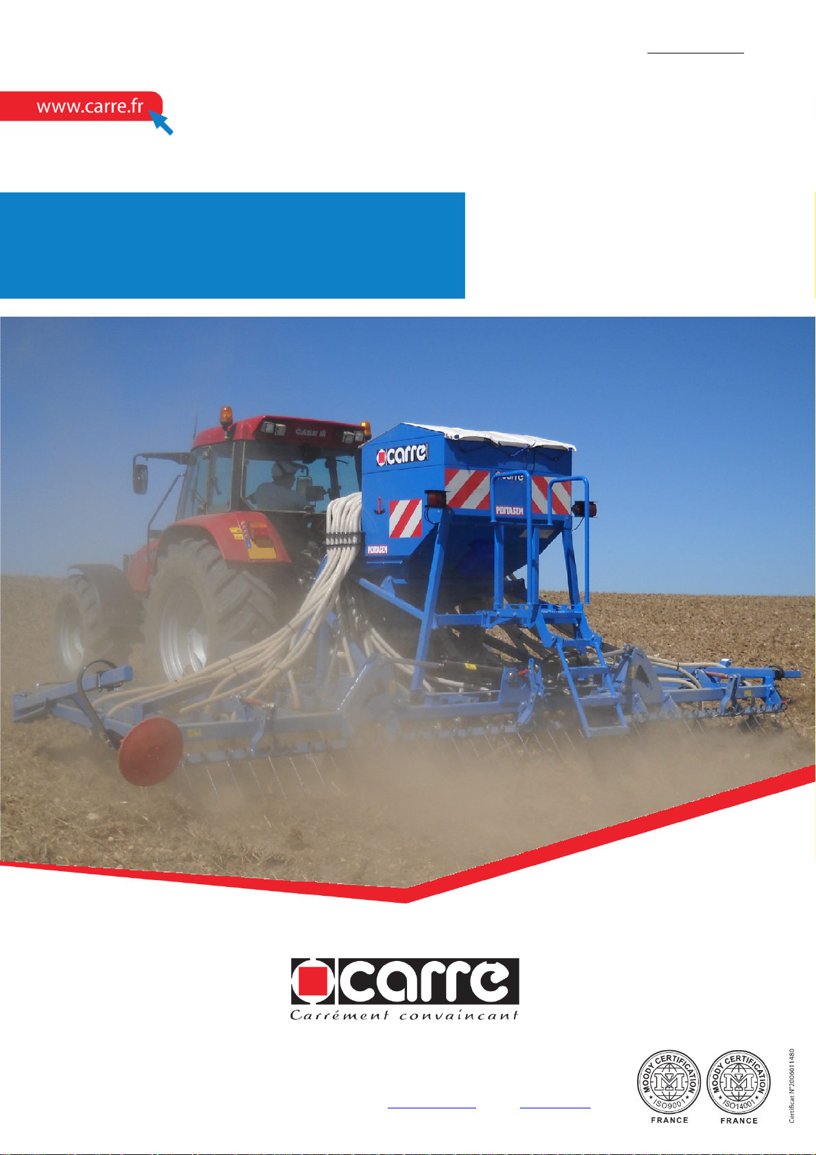
PENTASEM
Assembly - Use
Ref. 38011901
Updated 10.11.10
CARRE sas • CONSTRUCTIONS MECANIQUES • Z.A Les Fours • BP 6
Tel. 02 51 07 82 35 • Fax 02 51 07 80 75 • http://www.carre.fr • Email: carre@carre.fr
85140 SAINT MARTIN DES NOYERS • FRANCE


CONTENTS
Page
1
2
3
INTRODUCTION ................................................................................. 3
SPECIFICATIONS .............................................................................. 3
SAFETY INSTRUCTIONS .................................................................. 5
3.1 Safety symbols ............................................................................................. 5
3.2 Usage as intended ....................................................................................... 6
3.3 General safety instructions........................................................................... 6
3.4 Safety in the public domain .......................................................................... 6
3.5 Accident prevention ..................................................................................... 7
3.6 Maintenance and repair ............................................................................... 7
4
5
OPERATOR CONTROLS ................................................................... 8
ASSEMBLY AND PUTTING INTO SERVICE ..................................... 8
5.1 Link on the tractor ........................................................................................ 8
5.2 Mounting the tines ........................................................................................ 8
5.3 Positioning the extensions ........................................................................... 9
5.4 Equipment .................................................................................................... 10
5.4.1 Front blade ................................................................................................... 10
5.4.2 Comb harrow Ø10 ........................................................................................ 10
5.4.3 Rubber tyre wheel ........................................................................................ 10
5.4.4 Blower .......................................................................................................... 11
5.5 Adjusting and using the sower before sowing .............................................. 12
5.5.1 Markers ........................................................................................................ 12
5.5.2 Pre-emergence markers ............................................................................. 12
5.5.3 Sowing depth adjustment ............................................................................ 13
5.5.4 Flow test ....................................................................................................... 14
5.5.5 Track marker adjustment ............................................................................ 18
5.5.6 Sower control ............................................................................................... 19
5.6 Using the sower during work ........................................................................ 20
5.7 Usage after work .......................................................................................... 21
5.7.1 Emptying the hopper and the dispenser ....................................................... 21
5.7.2 Sower storage .............................................................................................. 21
5.8 Using the case
6
MAINTENANCE .................................................................................. 38
.......................................................................................
22
6.1 Maintenance carried out by the user ............................................................ 38
6.2 Maintenance carried out by specialised personnel ...................................... 38
6.3 Troubleshooting ........................................................................................... 39
6.4 Tightening torque ......................................................................................... 40
7
8
DISPOSAL .......................................................................................... 41
CE DECLARATION OF CONFORMITY ............................................. 42
2
1 INTRODUCTION
Before using the PENTASEM sower, we recommend that you read this
manual carefully and that you scrupulously comply with the instructions. As such,
you will avoid putting yourself into a dangerous situation, you will reduce putting into
service time and the risk of undesirable incidents outside the warranty period.
Always keep this manual handy
Your CARRÉ reseller will provide you with advice so that you can obtain full
satisfaction from your machine.
Comply with the safety instructions
Warning symbol
CARRÉ cannot be held liable for any damage and operating incidents occurring
subsequent to usage that does comply with the instructions in this manual.
Warranty: Please fill out the warranty certificate enclosed with the machine
and return it as soon as possible to the indicated address in order to activate
your warranty.
2 SPECIFICATIONS (a)
Description of the PENTASEM
PENTASEM is used for planting a crop in simplified sowing at high speed.
Available in 5 widths, 3m50 as fixed, 4m00, 4m80, 5m60 and 6m00 as foldable.
Planting is accomplished with 45x12 right tines with seed diffuser.
Power required:
From 100 to 150 hp according to the widths.
Operating speed:
Up to 12 Km/h, varies according to method of use.
Static airborne noise:
None of the equipment produces when empty an equivalent A-weighted sound
pressure level exceeding 100 dB at a distance of 1m.
3
Technical characteristics (a):
Number of
Working
Transport
Power
Code
Weight
Code
Weight
Code
Weight
Options (b) (c)
Code
Weight
PENTASEM
Code PTS 3500 PTS 4000 PTS 4800 PTS 5600 PTS 6000
Weight
rows
Interline
width (m)
width (m)
required (hp)
Planting
1045 1670 1735 1790 1840
Specific characteristics
28 32 32 40 40
125 mm 125 mm 150 mm 140 mm 150 mm
3m50 4m00 4m80 5m60 6m00
3m50 3m20 / 3 parts 3m20 / 3 parts 3m20 / 3 parts 3m20 / 3 parts
100 120 150 150 150
45x12 right tines with seed diffuser
FRONT EQUIPMENT
FB – FLEXIBOARD front blade
FB35 00 FB40 00 FB48 00 FB56 00 FB60 00
145 184 198 206 210
REAR EQUIPMENT
HPS – Comb harrow Ø10 on one row with BF link
HPS35 00 HPS40 00 HPS48 00 HPS56 00 HPS60 00
57 96 100 105 117
BF – Rubber tyre wheel L=50 mm
BF35 00 BF40 00 BF48 00 BF56 00 BF60 00
140 202 238 246 250
- Hydraulic blower unit connected to tractor oil intake (for tractor
without flow adjustment)
- 300 litre hopper side board
- Distribution head cover 40/20
- Distribution head cover 32/16
- Descent seal cap
- Single disc pre-emergence marker
- Dual disc pre-emergence marker
- Electric track marker valve
- Set of 4 stands
-
Pair of fixed pneumatic depth gauge wheels on extensions
11916
11911
VN90048027
VN90048025
119005
11955
11954
VN90050044
11702
11925
18
17
5.3
2.8
30
60
0.5
30
130
(a) The technical characteristics, dimensions and weights are provided for the purposes of
information; these may change.
(b) Incomplete list.
(c) Regardless of the width of the device.
-
4
3 SAFETY INSTRUCTIONS
dangerous area.
dangerous area.
belt protective
cover in place
footstep while
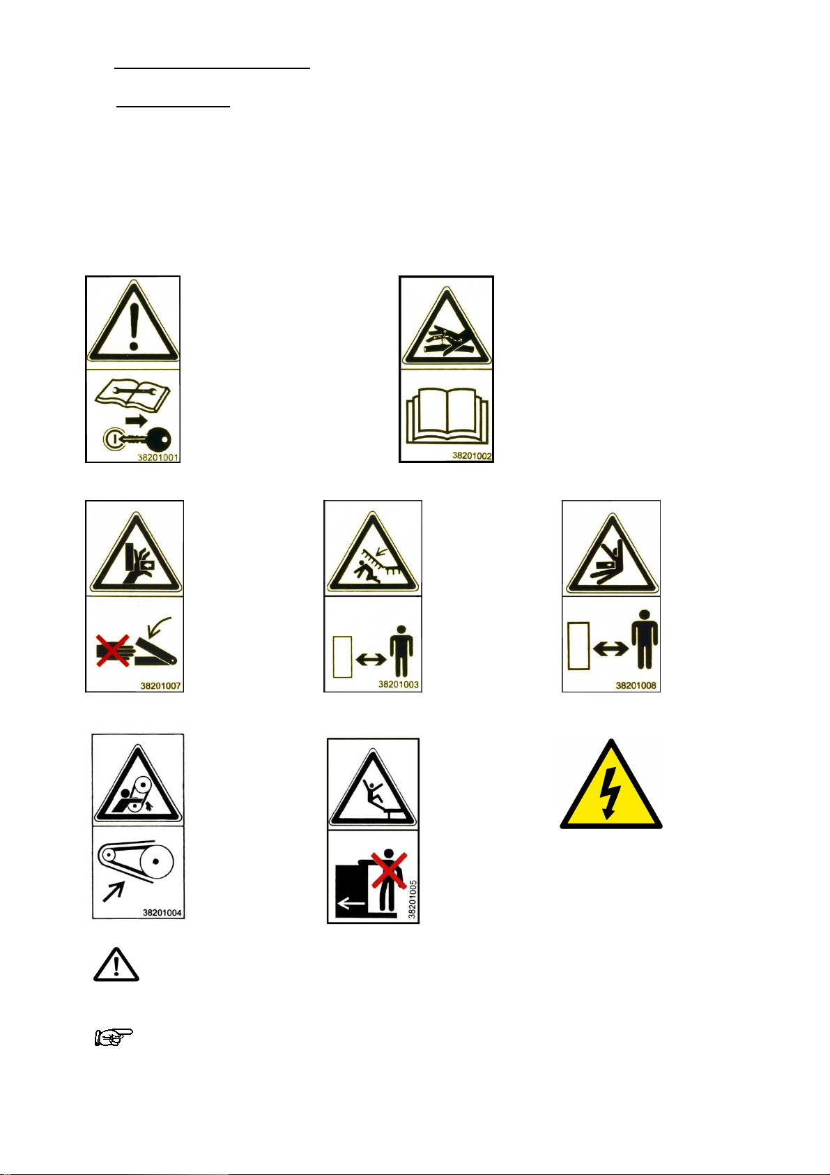
3.1 Safety symbols
On the machine
Make sure that the warnings and pictograms remain clean and visible at all times. If they
become deteriorated, ask your manufacturer (or distributor) for new stickers.
If repair work is done, ensure that the spare parts have the same stickers as the original
parts.
Read the maintenance
booklet and the safety
instructions before
turning on the
In order to prevent leaks
in the hydraulic circuit,
follow the instructions in
the maintenance booklet
machine.
Before any
intervention, turn off
the tractor engine and
remove the key.
Never place
hands in the
danger areas
when the parts
are in motion,
there is a risk of
pinching.
Have everyone
leave the
There is a risk
of crushing
Have everyone
leave the
There is a risk
of crushing
²
Keep the
sower's drive
in order to
protect the
hands
Do not step
on the
the machine
is moving
Electrical
installation
Triangle indicating DANGER each time that the risk of an accident is high or when
the equipment may be damaged.
This arrow indicates areas where advice is provided on facilitating the work.
5

3.2 Usage as intended
PENTASEM is designed to be used for planting a crop in simplified sowing at high speed.
Any use other than the latter shall be considered as non-compliant with the intended use
and shall release the manufacturer from any liability in the event of prejudice; the user
alone shall incur the risks that result from such use.
Comply with all of the installation, operating, adjusting, maintenance and repair instructions
contained in this notice.
Use only spare parts and accessories that comply with the manufacturer's
recommendations.
The use, maintenance and overhauling of the PENTASEM must be entrusted only to
people who are familiar with and who are informed of the possible dangers.
Do not modify or have your machine and its accessories modified by another person
(mechanical, electrical, hydraulic, pneumatic characteristics), without first obtaining
approval from your manufacturer.
Not complying with these rules can make your machine dangerous. In the event of damage
or injury, the manufacturer shall be released from any liability.
Moreover, the special instructions concerning the prevention of accidents must be complied
with, as well as the general rules in terms of technical safety, occupational medicine and
legislation concerning the use of roads.
The manufacturer declines all liability in the event of prejudice resulting from a modification
made to the PENTASEM without its approval.
3.3 General safety instructions
Only use the PENTASEM if all of the protective and safety devices are installed and are
operating correctly.
Check that the screws are tight on a regular basis and tighten them if necessary, especially
the clamping screws for the tines and the bearings on the equipment.
In the event of operating incidents, stop the machine immediately, then repair the
breakdown or have it repaired immediately.
3.4 Safety in the public domain
Before driving on a road, you must become familiar with the operation of all of the controls.
Comply with the rules of the road when you move into the public domain (roads, paths and
squares). Make sure beforehand that the condition of the PENTASEM is compliant with the
regulations set forth in the rules of the road.
Comply with authorised transport width limitations.
Adjust your speed and driving style to the land, roads and paths. Remain vigilant and
cautious!
At all times and in particular on sloped and broken land, operate the machine at slow
speed, especially when turning and do not change direction abruptly.
Do not brake or start abruptly while going up or down a slope.
Driving is influenced by the machine coupled to the tractor. Comply with the axle load limit
and the gross weight so that steering and braking precision are maintained and, when
turning, give particular attention to the overhang and the inertia mass of the PENTASEM.
Do not transport anyone on the PENTASEM.
6

3.5 Accident prevention
In addition to the recommendation in this manual, follow the instructions of the farming
mutual insurance companies.
During the hitching of the PENTASEM to the tractor:
- Ensure that the PENTASEM is resting on stable ground.
- Never remain between the tractor and the PENTASEM; there is a risk of an accident.
- Operate the 3-point hydraulic lift system slowly and with caution.
- Check that the 3-point hitching categories of the tractor and of the PENTASEM
correspond.
During use:
- Before turning on the machine, ensure that no one is within the vicinity of the machine.
Ensure that there is sufficient visibility.
- Do not transport anyone on the hoeing machine during work.
- None of the protective devices prescribed and delivered with the machine are to be
removed.
- Make sure that no one is in the pivoting area of the extensions that can be folded, the
markers and any pre-emergence markers.
- While operating and when in motion, the PENTASEM causes the projection of soil and
stones. Ensure that no one is within the vicinity of the machine.
During the operation of the power take-off of the sower:
- Comply with the instructions in the U-joint transmission manual.
- Use only U-joint transmission with their regulatory protectors (the tube and cone must
be mounted).
- Mount the U-joint transmission shaft only if the motor of the tractor is stopped and if the
power take-off is disconnected.
- Comply with the overlapping prescribed for the sliding shafts in transport and working
position.
- The U-joint transmission protectors must be immobilised in rotation.
- Do not turn on the power take-off until there is no one within in the vicinity of the sower.
- The rotating speed of the tractor's power take-off must correspond to the authorised
rotating speed of the sower.
- WARNING: Due to its inertia, the power take-off continues to rotate after it has been
disconnected. Stay away from the device during this lapse of time and do not intervene
on the latter until it has come to a complete stop.
- Put the protective sleeve back on tractor's power take-off, as soon as the U-joint shaft is
no longer connected to it.
3.6 Maintenance and repair
- Comply with the time frames that are recommended or indicated in this manual when
carrying out scheduled inspections and verifications.
- Before beginning any maintenance or repair work, make sure that the hydraulic
installation is not under pressure, and stop the tractor's power take-off and motor.
Uncouple the PENTASEM from the tractor.
- Carry out maintenance or repair work only if the PENTASEM is resting flat on stable
ground and where there is no risk of tipping.
- Do not carry out any maintenance work on a raised device without having installed the
appropriate supports for safety reasons.
7
- When assembling and disassembling, use appropriate means that do not compromise
your safety.
- Take advantage when cleaning the PENTASEM at the end of each crop year at least,
to check that the hydraulic lines are properly sealed, the connections are tight and that
there are no defects caused by friction. Replace anything that is deteriorated
immediately.
- When replacing wearing parts, use suitable tools and wear gloves.
- Spare parts must meet the manufacturer's technical requirements, which is always the
case with original parts.
- Before carrying out any electrical welding work on the PENTASEM, when it is hitched to
the tractor, disconnect the battery cables.
4 OPERATOR CONTROLS
With regards to hitching, and for safety reasons, the original pins must be used. In
order to prevent loss, the pins as well as their lynch pins are connected to the PENTASEM
by a chain.
5 ASSEMBLY AND PUTTING INTO SERVICE
5.1 Link on the tractor
The PENTASEM is equipped with a 3-point pin coupling between yoke No. 3 and
reversible pin diameter No. 2 and No. 3, in accordance with standard NF U 14032.
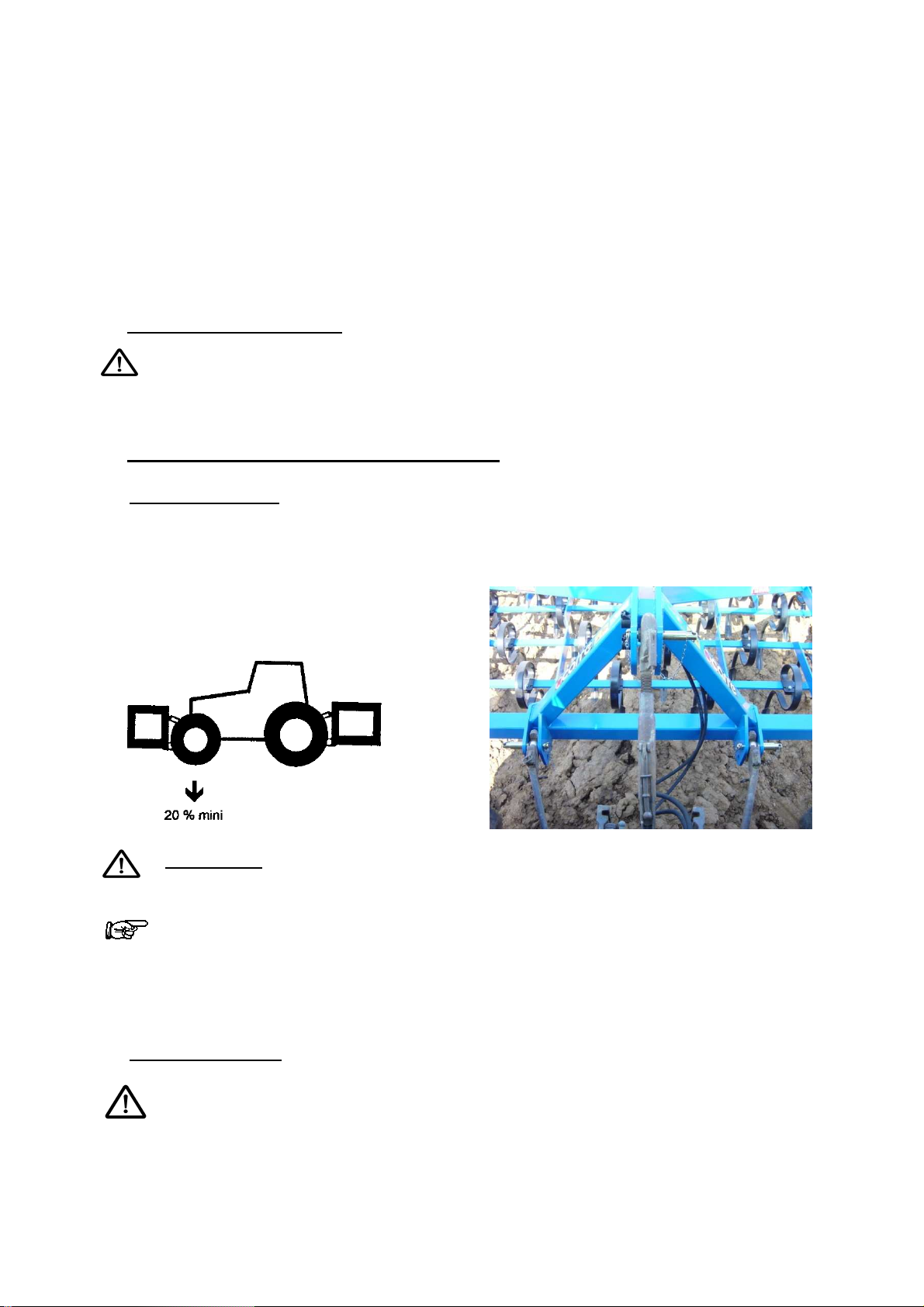
WARNING: Never remain between the tractor and the PENTASEM; there is a risk
of an accident.
The "Tractor + PENTASEM" unit has a substantial mass. In order to allow for
sufficient static stability, the load of the front axle of the tractor must not be less
than 20% of the empty weight of the tractor. For this, the most practical method consists in
weight the front of the tractor on a scale and comparing the result with the recommended
value in the tractor's user manual. Add weight to the front of the tractor if necessary.
5.2 Mounting the tines
Planting seeds is accomplished with a 45x12 right tine with diffuser.
The tine pitch depends on the PENTASEM model (125 mm pitch for the 3m50 and
4m00 model; 140 mm pitch for the 5m60 et 150 mm pitch for the 4m80 and the 6m00).
8
Adjust the step screw in contact with
Retract the step screw to the maximum for
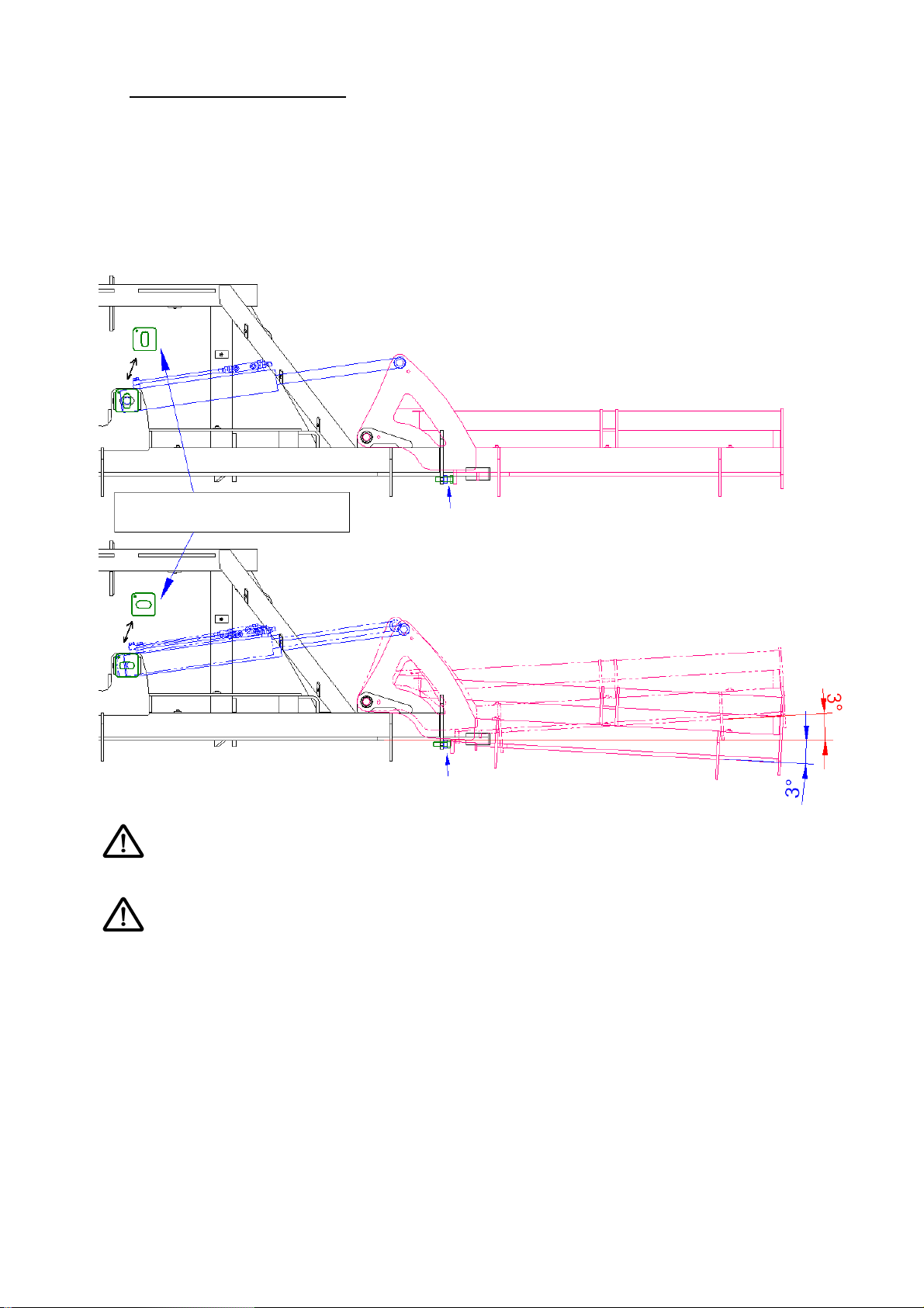
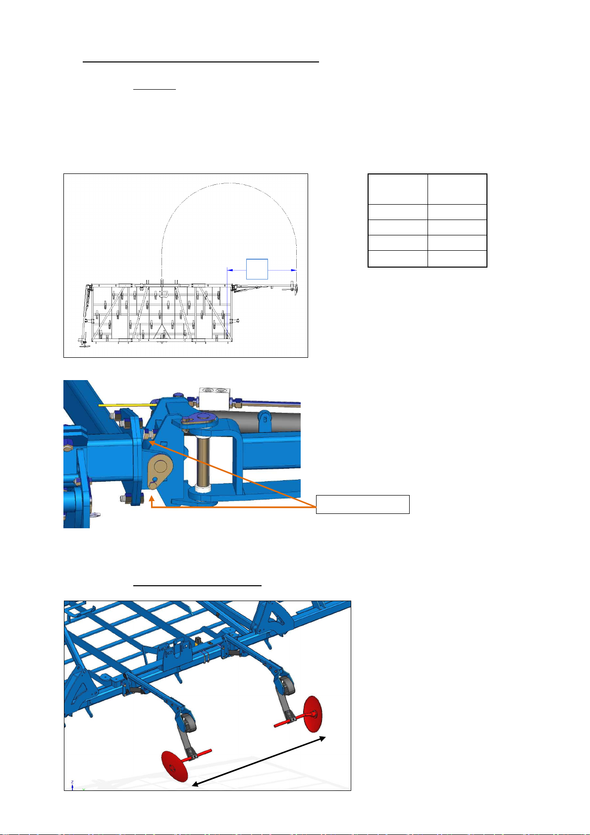
5.3 Positioning the extensions
The extensions can be in a fixed position or in a floating position. The floating position is
used to follow the differences in level of the ground in order to obtain even sowing in liaison
with the optional wheels on the extensions.
The PENTASEM must be placed on flat ground in unfolded position when switching from
the fixed position to the floating position. Remove the pin from the swivel cylinder of the
extensions and direct the shims (see drawing below).
Positioning the shims
the extension in horizontal position
the oscillation of the extension
Give attention to the adjusting of the lower stop according to the desired position of
the extensions.
Never switch from the floating or fixed position with the machine folded
9
setting
setting
5.4 Equipment
5.4.1 FLEXIBOARD front blade
The front blade is mounted on the front beam of the PENTASEM. It is provided with several
spring blades, and participates in levelling the ground before the sowing tine passes.
Adjustments are made by the push bars and can be turned off.
Blade adjustment
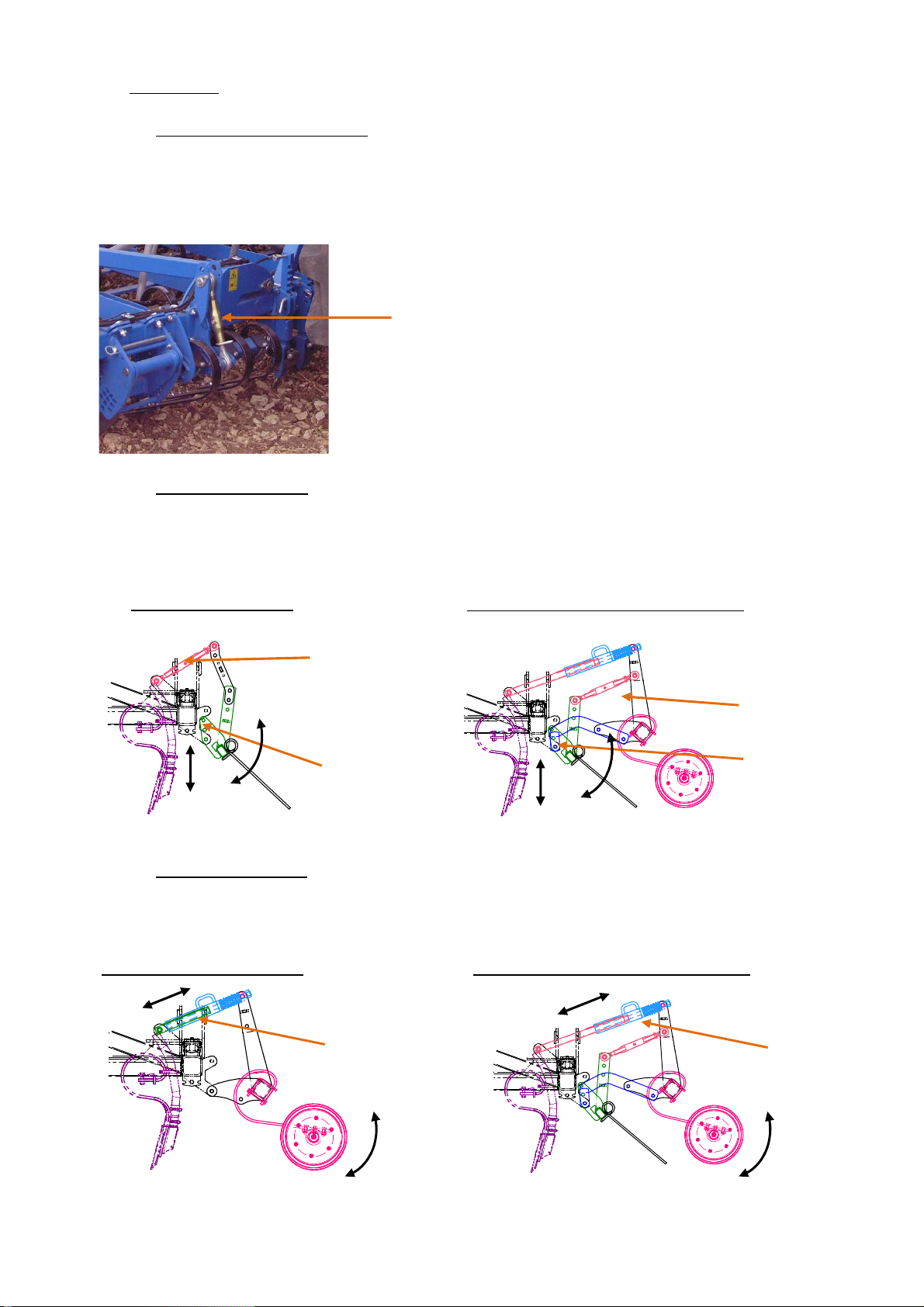
5.4.2 Comb harrow Ø10
The comb harrow is mounted behind the sowing tines, and allows the sowing to be finished
by closing up the furrows evenly.
It is used alone or along with the rubber tyre wheels.
Comb harrow alone
Comb harrow + rubber tyre wheel
Harrow
inclination
Harrow
inclination
Harrow height
setting
Harrow height
setting
5.4.3 Rubber tyre wheel
The rubber tyre wheels are mounted behind the sowing tines. They allow for regular and
individual consolidation of the sowing coulter.
Depth
adjustment
Comb harrow + rubber tyre wheel Rubber tyre wheel alone
Depth
adjustment
10
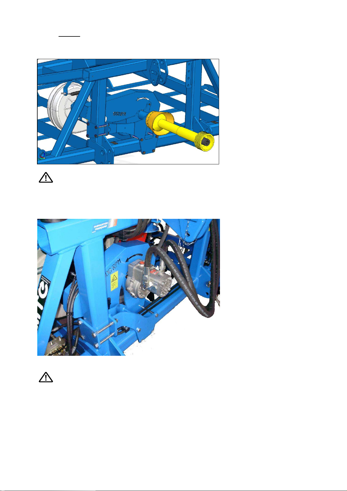
5.4.4 Blower
Mechanical blower
Required nominal speed is 1000 rpm PTO which is a blower rotation of 4300 rpm.
At the end of the plot, reduce the PTO to a minimum in order to avoid a power loss
in blower speed.
Hydraulic blower
Hydraulic supply to be connected as single-acting of the tractor.
Connect the return to the free return of the tractor, with pressure less than 5 bars,
otherwise the shaft seal will be destroyed.
Oil flow: 40l/min which is a blower rotation of 4300 rpm.
11
Adjusting screw
5.5 Adjusting and using the sower before sowing
5.5.1 Markers
Adjusting the markers
Disc markers can be adjusted in the middle of the tractor. They mark a line on the
ground to follow during the return. The middle of the tractor as such passes along
this line on the ground
X
Adjusting marker inclination
The inclination is adjusted using 2 adjusting
screws. It can be placed in a fixed position
or in a floating position.
Sower
width
4m00 206.2
4m80 247.5
5m60 287
6m00 307.5
X (cm)
The marker disc is adjusted on the ground;
measure the distance X between the
middle of the last tine and the middle of
the disc (see the table according to the
width of the sower).
The marker sequence is done at the end of the field using the control of a single dualaction distributor.
5.5.2 Pre-emergence markers
The single- or dual-disc pre-
emergence markers are lowered
simultaneously with the track
marker valve control in order to
create lines for the treatment
machines.
They are activated at the same
time as the track marker valves of
the sprayer track.
12
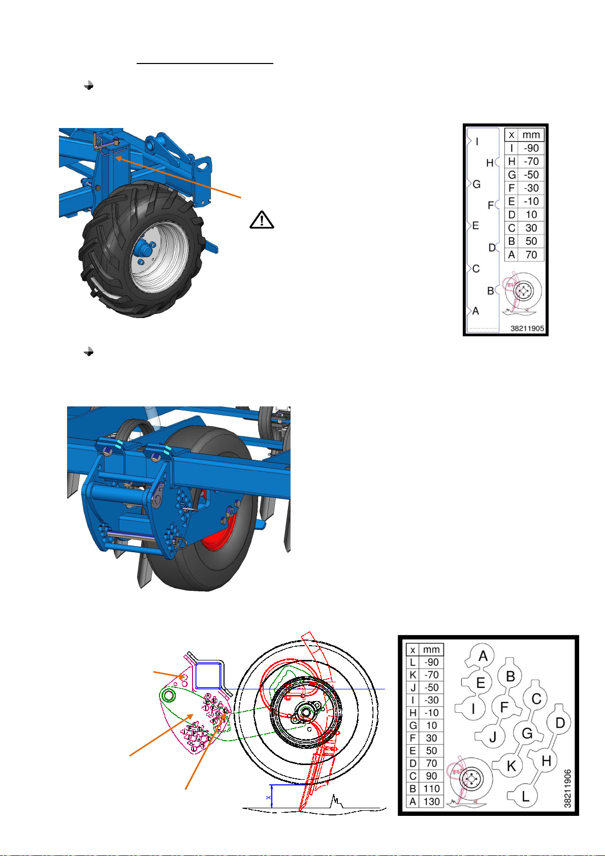
5.5.3 Sowing depth adjustment
Depth gauge wheel on fixed chassis.
The depth adjustment wheels allow the working depth to be controlled reliably.
Adjusting the depth is carried out
using the crank screw.
The wheels must be set
identically on each side of the
sower.
Depth gauge wheel on extensions
The depth gauge wheels on the extensions allows the working depth to be controlled when
the extensions are in floating position, in order to follow the differences in level of the land.
Depth adjustment is carried out using 2 pins
Position of the pin
if work as
floating
Lower
stop
Upper
stop
13

5.5.4 Flow test
1
2
3
4
5
6 9
8
7
Determining the setting value
For a correct adjustment, it must be determined whether you are dealing with a common
seed or fine seeds.
-
Common seed: between 4 and 10 mm
- Fine seed: between 1.5 and 4 mm
Following the handling instructions in the order listed and the adjustment table in order
to control the flow. Use the microdosage for sowing fine seeds and small quantities.
Distribution + blower details
1- Case
2- Graduation sector
3- Inverter
4- Drain trapdoor
5- Threaded rod
6- Microdosage sprocket
7- Gear reducer
8- Elbow
9- Spring clamp for the blower air adjustment flap
Table of settings
The values shown in this table of settings are provided solely for the purposes of
information, as the specific weight and the calibre of the seed are often very different. The
correct value is determined by carrying out a flow inspection at a fixed station. The volume
determined as such will always correspond the the seed flow (for the same seed).
14

(seed value between 4 and 10mm)
*:
Fine seed
(seed value between 1.5 and 4mm
)
Common seed
TYPES OF SEED
In case of a low flow (for example: cell width < 25mm) more regular sowing may possibly be obtained by activating micro dosage even in a normal sowing range
15

During the fixed station flow inspection, proceed as follows:
B
1- Do you want to perform a flow control for common seed or with fine seed?
2- Types of seed
a-
For common seed, place the inverter C on the dispenser and the spring clamp of the
blower adjustment flap to open position [ 1 ] (in the axis of the pipe) and place
sprocket A in sprocket B.
2
A
b- Adjust smaller doses only if the dispenser is running or if the hopper is empty.
Otherwise, you run the risk of deteriorating the dispenser by pressing on the seed.
For fine seed, turn the threaded rod until the value 0 is shown in the graduated
sector. Then turn the inverter C to the right, until it snaps into the groove of the hex
shaft.
Also position the spring clamp of the blower air adjustment flap to position [ 2 ] and
take out sprocket A so that it drives sprocket C.
2
C
A
B
C
3- Use the settings table to locate the value that corresponds to the quantity to sow.
4- The graduated sector indicates values from 0 to 110 (only up to 25 for small seeds).
Turn the threaded rod until the value of the setting appears against the notch of the
case.
1
16

5- Close the drain trapdoor
6- Pour the seed into the hopper
7- Remove the elbow located under the injector after loosening the wing nut
8- Place the basin (fixed under the hopper) under the opening of the injector to collect
the seed from the flow test.
9- Perform the weighings (see procedure on page 30).
10- Then attach the elbow between the injector and the blower.
The flow inspection test is complete.
Flow test with microdosage.
With microdosage, it is possible to sow small seeds and very small quantities per hectare.
The advantage with microdosing compared to a normal rotating speed for small seeds
resides in the fact that the opening of the cells is twice as large for the same flow. This
results is better self-cleaning of the cells.
Pull the red sprocket towards the exterior until it snaps in. The microdosage is connected.
The value of the setting must be read from the table for small seeds.
A cell cleaning brush, for sowing small seeds, is fixed to the inside of the case of the
dispenser. This prevents the grooves from becoming clogged when treated seed is used,
for example. It is located under the steel sheet that covers the injector behind the
sprockets. Check that it is in good condition before beginning to sow.
For common seed, remove the brush
17

Sower
Sprayer (M)
Cleaning brush
5.5.5 Track marker adjustment
Passage marks can be marked out automatically with the device that electronically shuts
off ploughshare power.
In order to mark out the lines, ploughshare power must be cut off by closing the
corresponding electric valves. The track of the tractor that will be used later for spreading
fertiliser or for spraying is determinant in choosing the ploughshares that have to be closed.
The power must be cut off for several ploughshares located next to each other (2 on the
right and 2 on the left as standard, with a possibility of 3 on the right and 3 on the left for
wider wheels).
A rate determine the moment when the track marking operation is carried out.
Working width of the treatment machine
--------------------------------------------------------------- = Track marking rate
Sower working width
Example: With a 4m80 sower and a sprayer with a working width of 24m:
24
---- = 5 = Track marking rate
4.8
The following table shows the most common combinations for marking out lines.
8 9 12 15 18 20 21 24 27 28 30 32 33 36 38 40 42
4m00 2 3 5 6 7 8 9 10
4m80 5
5m60 5
6m00 2 3 4 5 6 8
The even rates are for tracking marking with two passes. Lines for passes that are marked
out in a single pass are however more accurate than in they are marked out in two passes.
For this reason, lines can also be marked out in a single pass by using the even rates.
18

In this case, sowing must be carried out during the first pass with only half the working
width of the sower, or distribution must be disconnected for the corresponding portion of
the sprayer or fertiliser distributor.
Fertilisation or
treatment
machine track
Even rate
Odd rate
The odd rates (i.e. 3, 5, 7, etc.) mark out lines in a single pass.
Before using for the first time, check that the lines are marked out with a spacing
that complies with what you are looking for! The sowing tines in the line must not
leave seed.
5.5.6 Sower control
Before leaving the farm to go to the place of use, you are advised to check the following:
• The sower is compliant with the instructions concerning transport on roads.
• The hitching of the sower to the tractor.
• The setting of the track marking (rate)
• The opening and closing of the electric valves by the track marking device.
• The track marking and the electronic control of the sower when changing tractors.
• All of the sowing tines sow. (Turn on the blower and allow the distribution to operate,
by passing in front of the radar, seed should then be on the ground under each tine).
• The elbow is positioned, as instructed, under the injector.
• The beige inverter on the dispenser and the air flap on the blower are in the desired
position.
• The divider cover in the distribution head, all the rows or 1 out of 2.
• The closing of the drain trapdoor.
• The filtering sieve in the hopper.
19

5.6 Using the sower during work
Adapt the sower to the work in the field.
In the field, the sower must be switched from the transport position to the working position
in order to operate.
Before using the PENTASEM, follow these instructions:
1. Couple the PENTASEM to the tractor.
2. Adjust the sower's plumb line via the angle indicator / hopper side
3. Connect the sower's hydraulic couplers to that of the tractor
4. Connect the electronic case to the tractor's 12-volt power supply
5. Connect the lighting to the tractor
6. Install the mechanical drive for the PTO 1000 rpm or connect the hydraulic unit (free
return)
7. Adjust the radar stop sensor to the 3rd point of the tractor
8.
Position the blower flap to microdosage (fine seed: colza, etc.) or normal dosage
(common seed: wheat, etc.)
9. Position the dispenser inverter to micro dosage or normal dosage
10. Adjust the sower value according to the table of settings
11. Adjust the gearing to micro dosage or normal dosage
12. Install the cleaning brush for fine seed or remove it for common seed
13. Install the simple cover or divider / distribution head
14. Adjust the hopper level sensor
15. Fill the seed hopper (make sure the drain trapdoor is closed)
16. Carry out a flow test at a fixed station, and refer to the instructions for use for the
RDS "Artemis" case
17. Adjust the sowing depth on the central portion with the depth gauge wheels
(pressure = 2.25 bars)
18. Install the fixed or floating position on the extensions
19. Adjust the sowing depth on the extensions with the depth gauge wheels (pressure =
7 bars)
20. Adjust the working depth of the marker erasers
21. Adjust the depth and the inclination of the comb harrow
22. Adjust the depth of the rubber tyre wheel (working free spring)
23. Adjust the depth and the inclination of the "flexiboard" levelling blade
Once all of these operations have been verified or carried out, turn on the sower's
blower to 1000 rpm, with the unit unfolded and set on the ground in the plot:
Make sure that after a brief manual pass in front of the radar, all of the descents are
distributing seed (except for alternating row sowing)
Make sure that the track marker cycle is operating correctly
Sow over a few meters to check sowing depth then adjust the settings more finely if
necessary.
20

Sowing control
Sowing perfection primarily depends on how it is controlled. Sowing must be checked after
having progressed a few meters and also from time to time on large plots.
• Are the sowing depth and the seed covering sufficient (compare the sowing tine
rows)?
• Are the tines sowing a volume that is identical to that of the tests (especially with
small seed)?
• Is the seed flowing perfectly through the electric valves?
• Are the tines clogged?
• Are the tines hindered by plant debris?
• Are the markers correctly adjusted?
• Are the electric valves operating perfectly?
• Are the electric valves correctly adjusted at the distribution head?
• Does the speed of the power take-off or of the hydraulic blower remain constant
during sowing?
• Are there any bridges formed in the hopper (especially with bearded seed)?
If you interrupt working because of a clog, the machine must be raised and backed up
about one meter before resuming in order to avoid missing areas.
How to make a U-turn with the sower
Just before reaching the end of the field or before initiating a U-turn, reduce engine speed
and raise the sower while moving. After completing the U-turn, set the sower back down
and resume service, at the required engine speed and power take-off, at about one meter
before the line starting where you want to sow. A short amount of time is needed for the
seed to be carried from the dispenser to the sowing tines, and as such the pre-start
function must be used (§5.8 - B6).
5.7 Usage after work
5.7.1 Emptying the hopper and the dispenser
Place the sower on firm and very flat land.
After sowing, the hopper and the dispenser must be completely emptied.
If the hopper is almost empty, place a container under the drain trapdoor and open the
latter.
Press the white push-button, which will remove the remaining seed. Where applicable, any
clogging and deposits must be removed with a brush. Leave the dispenser open. As such,
you will prevent rodents from causing any damage.
5.7.2 Sower storage
The sower must be placed horizontally on very firm ground. The PENTASEM must be in
folded position. Raise the marker erasers where applicable. The hydraulic and electric
connectors and the U-joint transmission shaft if there is one must then be disassembled.
21

5.8 USING THE CASE
A. GENERAL PRESENTATION ............................................................................ 23
A.1 The Artémis system .................................................................................... 23
A.2 Main functions ........................................................................................... 24
A.3 Data Regulation and Recording Modes ................................................... 25
Automatic Regulation Mode ......................................................................... 25
Regulation Mode with Dose Modulation....................................................... 25
A.4 Psi console buttons ................................................................................... 25
B. OPERATION ...................................................................................................... 25
B.1 Status icons ............................................................................................... 26
B.2 'MAIN' screen ............................................................................................. 26
B.2.1 Forward speed display and alarm functions ............................................ 27
B.2.2 Marking Functions/Statuses .................................................................... 28
B.2.3 Manually increasing the pass number ..................................................... 28
B.2.4 Freezing the pass number ....................................................................... 28
B.3 'RATE' sowing dose screen ...................................................................... 28
2.3.1 Adjusting / forcing the target dose ........................................................... 29
B.4 'INFO' screen .............................................................................................. 30
B.5 Marking
B.6 Pre-start function ....................................................................................... 31
B.7 Electric motor – manual forcing/sowing a half-width ............................. 32
B.8 Product CALIBRATION .............................................................................. 32
2.8.1 Initial CALIBRATION of the product ........................................................ 32
2.8.2 ‘CALIBRATION NUDGE’ – Adjusts the calibration factor ........................ 34
B.9 Setting the turbine speed and hopper empty alarms ............................. 35
B.10 Simulating forward speed ......................................................................... 35
B.11 Selecting the units / ‘Pitch’ for the % dose .............................................. 36
C. RECORDING DATA AND MODULATING DOSES ........................................... 36
22

(Radar)
Track marker
A. GENERAL PRESENTATION
A.1
The Artémis system
Figure 1
Manual
Calibration
Button
power
Motor
‘MCM’
A/N Module
(Motor)
Marking
Switch
PSi Console Electrical
Distribution
sensor
Turbine
speed
sensor
Speed
Sensor
valve
Hopper
empty
sensor
Marker
sensors
‘HBM’
A/N Module
23

Figure 1 shows the various components of an Artémis installation with single or
dual motors. All sowing configurations are possible (one or two motors with one or
two dispensers) and the Psi Artémis console can be configured as desired.
PRODUCT
SEED
SEED
+
FERTILISER
CONSOLE SETTING
DISPENSER/MOTOR
CONFIGURATION
SINGLE MOTOR/
CONSOLE
SETTING
DISPENSER
SINGLE MOTOR/
DUAL DISPENSER
2 MOTORS /
SINGLE DISPENSER
SINGLE MOTOR/
DISPENSER (SEED)
+
SINGLE MOTOR/
DISPENSER
(FERTILISER)
SINGLE MOTOR/
DUAL DISPENSER
(SEED)
+
SINGLE MOTOR/
DUAL DISPENSER
(FERTILISER)
A few of the screen pages are slightly different, according to the sower
configuration selected. Look for the symbols above next to the text.
A.2 Main functions
Artémis is designed to allow for automatic adjustment at a variable dose for any
sower using an Accord dispenser. At any time, you can manually modulate the
preset dose in order to adapt it to areas in the plot.
The basic functions are:
• Variable dose regulation
• Marking
• Forward speed alarms
• Hopper empty alarm
• Turbine speed alarm
• Information on totals (surface area, quantities)
24

The console has a special mode in order to easily CALIBRATE the dispenser.
In this CALIBRATION mode, each dispenser is controlled by the "manual calibration
button" to distribute the product (figure 1).
During normal operation, the system is automatically started and stopped by a
magnetic sensor when the sower is raised and lowered for work. According to the
type of installation, this sensor is actuated either by the movement of a wheel or by
the markers.
A.3 Data Regulation and Recording Modes
Automatic Regulation Mode
The sowing dose is automatically adjusted according to the forward speed, in
order to ensure that the current sowing dose constantly corresponds to the preset
target dose. The sowing dose can be increased or decreased manually in relation
to the preset target dose.
Parcel plan data ("work summary") can be recorded and stored in the console's
internal memory. Up to 75 summaries can be stored. With a GPS receiver and an
SD memory card, you can also record the vehicle's travel and the application data
in a "Dynamic record" file on the SD card. The work summary is also created in this
file.
Regulation Mode with Dose Modulation
This allows the system to be controlled by preset cards (prepared using highprecision farming software and the position provided by the DGPS). In order to
carry out automatic dose modulation, the PS 8000i requires a DGPS receiver and an
SD memory card in order to load the preset plans generated with high-precision
farming software.
A work record file is automatically created in the card for recording the data
which confirms the current application. The work summary is also created in this
file, and it can be opened in high-precision farming software.
A.4 Psi console buttons
All of the console functions are available through 9 buttons located at the edge
of the LCD screen.
Figure 1
Menu Buttons
On-Off Button
Sub-menu Buttons
Confirm
Delete
SD card reader
25

The 4 menu buttons located to the right of the screen (figure 1) display the
Forward speed
(Section 2.2.1)
Target
(Section 2.3)
Dispenser status
(Section
2.9)
S
urface
cut
DGPS
Signal
common screen pages (those that are used during normal operation). There are 3
basic screens: MAIN, RATE (dose) and INFO for the normal operating functions,
and a SETTINGS screen for the CALIBRATION functions.
The 5 sub-menu buttons below the screen control various display functions and the
setting for each basic screen page. Text or icons are displayed above each button
to indicate their function.
B. OPERATION
B.1 Status icons
All of the operation screens have a status bar at the top of the screen which
displays the time and a number of different icons. These icons indicate:
Working
Not working
NOTE: The memory card and GPS icons are displayed only when these functions
have been activated in the settings.
B.2 'MAIN' screen
The console always displays the MAIN screen when it is started up. The MAIN
screen is divided into 5 parts which display the following functions.
Figure 2: MAIN screen (single product / single dispenser)
Memory card
Inserted
Not inserted
No signal
Signal – no differential
Signal - differential OK
(Section 2.7)
‘Pre-start’ function
(Section 2.6)
Dipenser On-Off
(Manual forcing)
Marking status
(Section 2.5)
26
Turbine Speed
sowing dose
Marking – manual
increment
Stop automatic
incrementing of
marking
(Manual forcing)

NOTE: The status of the dispenser will be displayed differently according to the configuration of the
If the sower is working and
the forward speed is less
/h, this warning
logo will blink on the
screen with an audible
If the sower is working and
the forward speed is above
the maximum speed that
can be accepted by the
Artémis system, (indicated
on the RATE sowing dose
screen), this warning logo
will b
link on the screen with
sower (see figures 3 and 4).
Figure 3: MAIN screen (dual product / single dispenser)
Portion of the display that changes
Figure 4: MAIN screen (single product / dual dispenser)
Portion of the display that changes
B.2.1 Forward speed display and alarm functions
Smoothing of the displayed speed
Except in cases of quick changes in speed, the forward speed displayed at any
time will be the average speed calculated over 3 seconds.
Speed alarms on the MAIN screen
The console is programmed with high and low forward speed alarms.
than 0.5 km
alarm.
an audible alarm.
27

06.PCX
Maximum forward speed
When you set a new target dose in the RATE sowing dose screen, the console
recalculates and displays the maximum forward speed at which the dose can be
maintained (fig. 5). This is calculated using the sowing dose, the width of the
sower, the current CALIBRATION factor, the transmission ratio of the gearbox and
the maximum rotating speed of the motor.
Figure 5
UK566-
Press to go back to the RATE sowing dose screen.
NOTE: If the speed is too low, the operator has to open the dispenser and re-
calibrate in order to increase the calibration factor (see the 'CALIBRATION'
manual).
B.2.2 Marking Functions/Statuses
The MAIN screen shows the current marking status.
Marking mode: Symmetrical Asymmetric Left Asymmetric Right
Deployed status
( = ON)
Current pass
Target number
of passes
B.2.3 Manually increasing the pass number
When the console is turned on, the marking sequence always starts at '1'.
If necessary, press to select the correct pass number, for example to start
a parcel with a pass number other than ‘1’.
B.2.4 Freezing the pass number
Press to freeze the pass number displayed (for example, when sowing
around a pole where the sower needs to be raised and lowered several times).
The icon indicates that the pass number is frozen. Press to go back
to normal operation.
NOTE: The marking sequence is set in the SETTINGS screen (see section 2.5).
28

Current target dose
05.PCX
B.3 'RATE' sowing dose screen
This screen allows the sowing dose to be adjusted. Each of the kg/ha or
seeds/m2 units can be adjusted in the SETTINGS screen.
Figure 6: 'RATE' sowing dose screen - single product
% off target
‘Pitch’ of the dose
Target dose forced
manually by ‘pitch’ %
('pitch' % in the SETTINGS
screen)
Figure 7: RATE screen – dual product
Maximum forward
speed at which the
sowing dose can be
maintained
UK566-
Reset to the basic
target dose
NOTE: The maximum forward speed displayed is lower for the two products.
B.3.1. Adjusting / forcing the target dose
To adjust the target dose, simply enter the value and press the CONFIRM
button to confirm.
To set the target dose or manually adjust the dose for each product, first press
the CONFIRM button to select the SEED or FERTILISER product.
The application dose displayed in the MAIN screen is the
same as that displayed in the RATE sowing dose screen. If the
target dose is modified manually + or - in the RATE sowing dose screen,
this dose modification % will blink in the main screen.
When the system is operating with a preset card, this dose
modification % will blink only if the target dose was modified
using the ‘+’ or ‘–‘ buttons in the RATE sowing dose screen.
% off target
29

To force the target dose, use the
l
counter
)
SETTINGS screen.
To return to the target dose, use the button.
Both products are returned to their respective target dose
B.4 'INFO' screen
buttons. The 'pitch" % is set in the
Figure 8
Surface counter
Seed counter
Fertiliser counter
Displays the partial/tota
counters
Displays the grand total
There is a partial and a total counter for each
product (seed/product).
Resets the selected
(Not used)
(Not used
30

B.5 Marking
To set the marking mode, select the SETTINGS screen and press
Figure 9
The sprayer width
calculation is based
on the width of the
sower, the number
of target passes and
the marking mode.
Increase/decrease the
number of target passes
Mode select
The target number of passes can range up to 10, with symmetrical,
asymmetrical left or asymmetrical right marking modes.
Symmetric Symmetric left Symmetric right
The console displays the sower/sprayer width combination for the target
number of passes.
B.6 Pre-start function
This function is used especially with a front dosing hopper. The pre-start
function assists in avoiding unsowed areas especially in field corners. This starts
the dispenser at the CALIBRATION speed while the sower is still stopped, and as
such starts the primes the sower until the seed arrives at the sowing units just
before the sower starts to work.
The settings for this function are carried out through tests and error tests when
the system is turned on for the first time, and are then adjusted in the SETTINGS
menu.
To use the pre-start function, press in the MAIN screen before moving.
The motor will start at the CALIBRATION speed for a preset period of time, or
until the forward speed exceeds 2km/H, and then the automatic regulation takes
over.
31

B.7 Electric motor – manual forcing/sowing a half-width
Press the desired button .
The electric motor can be stopped manually as desired, for example:
(a) A portion of the plot needs another preparation of the land before sowing.
(b) With a front dosing hopper, the electric motor is stopped just before the end
of the pass in order to sow all of the seed in the pipes (the opposite of the
'pre-start' function).
(c) You want to sow a half-width.
B.8 Product CALIBRATION
B.8.1 Initial CALIBRATION of the product
Prepare the sower as normal for calibration with a bucket.
1. In the SETTINGS screen, press .
2a. If the console is configured for two products, select the product to calibrate
(fig. 10).
Figure 10: Dual product/single dispenser
2b. Or if configured for two dispensers, select the dispenser to calibrate (fig. 11).
Figure 11: Single product/dual dispenser
3. Otherwise, select the desired weight unit (kg or g), and then enter the weight
required for the calibration (fig. 12) and press CONFIRM. The dispenser starts
32

and runs at the programmed CALIBRATION speed to distribute the correct
quantity of product, and then stops.
NOTE: If a manual calibration button is used for the CALIBRATION, the calibration
procedure will start (fig. 13).
4. Weight the product obtained in the bucket, and enter this value (fig. 14). Then
press CONFIRM to confirm.
Figure 12
5. Press CONFIRM again, and the console recalculates and displays the new
CALIBRATION factor in kg/rev, the error %, and the maximum forward speed
allowed calculated according to the application dose that is set for the product
(fig.15).
Figure 15
6. Press CONFIRM again to confirm and store the new calibration factor, or press
ESC to go back to the SETTINGS screen.
The PARTIAL counter should be reset before starting to sow. This will allow you,
after having sowed a portion of the plot, to quantify any error in the calibration
factor by comparing the theoretical quantity of product sowed with the actual
quantity sowed that is known (an entire big bag for example).
You can then accurately adjust the calibration factor, is needed (see section
2.5.2).
NOTE: Systems mounted on an 'Accord' type dispenser.
33

When you switch from a low sowing dose to a high dose, for example from
3kg/ha to 100kg/ha, use the following procedure:
1. Open the dispenser to a raised position.
2. Start the calibration procedure, distribute a suitable quantity of product and
enter the weight obtained. The error will be substantial but press ENTER to
correct the calibration factor and continue (see Fig. 15).
3. The programme now needs the application dose (see Section 2.3).
4. Repeat the calibration procedure again, and this time the error should be low.
Accept the error and begin to sow.
When you switch from a high sowing dose to a low dose, for example from
100kg/ha to 3kg/ha, use the following procedure:
1. Open the dispenser to a lowered position.
2.
Start the calibration procedure, distribute a suitable quantity of product and
enter the weight obtained. If a manual calibration button is used, distribute a
small quantity of product and enter the weight. The error will be substantial
but press ENTER to correct the calibration factor and continue (see Fig. 15).
3. The programme now needs the application dose (see Section 2.3).
4. Repeat the calibration procedure again, and this time the error should be low.
Accept the error and begin to sow.
B.8.2 ‘CALIBRATION NUDGE’ – Adjusts the calibration factor
The ‘CALIBRATION nudge’ procedure allows you to adjust the existing
calibration factor without having to rerun the test with the bucket.
1. First, note the quantity of product displayed in the PARTIAL counter on the
INFO screen. This is the theoretical quantity that the instrument has calculated.
From the SETTINGS screen, either press
(Calibration Verification), or
(Sower SETTINGS).
If the console is configured for two products, select the product to calibrate (fig.
10).
Likewise, if the console is configured for two dispensers, select the right or left
side (fig. 11).
2. On each screen, press to select the ‘CALIBRATION Nudge’ screen (fig.
16).
Figure 16
34

3. Enter the theoretical weight that was noted from the INFO screen in step 1 and
press CONFIRM twice.
4. Enter the weight actually sowed and press CONFIRM twice.
5. The calibration factor is recalculated, and the error % and the maximum
forward speed (fig. 18) are also displayed. Press CONFIRM again to confirm
the new factor.
B.9 Setting the turbine speed and hopper empty alarms
To see the alarm thresholds (fig. 19), from the SETTINGS screen, press .
Figure 19
Low turbine speed alarm
High turbine speed alarm
Hopper empty alarm (ON/OFF)
To adjust the thresholds, enter the value and press CONFIRM.
B.10 Simulating forward speed
If the forward speed sensor (radar, encoder on a wheel, etc.) is no longer
working, you can continue sowing by simulating a forward speed. What is important
is to remember what your forward speed was before the breakdown, in order to
type the right simulation speed, otherwise the sowing density will not be correct. If
you sow at a speed that is higher than the simulation speed, you will under-dose
and vice-versa.
To set the simulated forward speed, from the SETTINGS screen, select ‘1
Operator Config’ then ‘2. Speed sensor factor’.
Press (fig. 20), then enter the value of the simulation speed (fig. 21).
Press the CONFIRM button to start the speed simulation.
Figure 20
During the speed simulation, the forward speed on the MAIN screen blinks (fig. 22)
35

NOTE: The pre-start function also works with speed simulation.
Functions that can
B.11 Selecting the units / ‘Pitch’ for the % dose
In the SETTINGS screen, select ‘1 Operator Config’ then ‘3. Adapt’.
Figure 23
If the console is configured for two products, first select the product with the
LEFT/RIGHT arrows (fig. 23).
Use the UP/DOWN arrows to select the parameter.
Use the LEFT/RIGHT arrows to select the units (kg/ha or seeds/m2).
Use the LEFT/RIGHT arrows to adjust the “pitch”, or enter the value with the
numeric keypad and press CONFIRM to confirm.
C. RECORDING DATA AND MODULATING DOSES
The data recording and dose modulation functions are available via the SETTINGS
screen.
1. Press to select the recording screen (fig. 24).
The console then detects the presence of a memory card.
2. Press the START button to go to the 'Start task' page (fig. 25).
Figure 24
Figure 25
be used with
Artémis
There are several functions possible. Only functions 1, 2 and 3 can be used with
Artémis.
36

1. Apply the plan (Dose modulation)
Several configurations are possible:
(a) The PS 8000i receives the dose from a preset plan located on the SD memory card
and controls the system according to this dose via the RDS regulation system. A
complete recording of the application carried out is generated and saved to the
memory card.
(b) The PS 8000i receives the dose from a preset plan located on the SD memory card
and sends this dose to another regulation case, which will carry out regulating the
system of another manufacturer. In this case, the PS 8000i is used as the controller.
(c) The PS 8000i receives the dose from another case (case which is used as a
controller) and controls the system via the RDS regulation system. The PS 8000i
can in return send back the current application dose to the other case.
All of these configurations allow the operator to modulate the doses.
For configurations (a) and (b), a complete recording of the application carried out is
generated and saved to the memory card. The record file for the work can be
opened in mapping software. The work summary is also created in this file.
2. Treatment recording (Dynamic data recording)
A compete record of the application carried out is generated, recording the dose
and other parameters ("tags", for example) in real time, combining this data with the
georeferenced position. The associated "Dynamic Recording" file can be opened in
mapping software. A large quantity of data is generated by dynamic recording and
must be saved to the SD memory card. The work summary is also created in this
file.
3. Summary recording (Internal data recording)
For simple recording for the purposes of traceability, you can record a summary of
each work in the internal memory, then download it directly to a computer, a
memory card or print it. The quantity of data in the summaries for each work is
small, and is stored in the console's internal memory. The console can store up to
75 summaries.
37

6 MAINTENANCE
6.1 Maintenance carried out by the user
AFTER THE FIRST HOUR OF USE
•
Check the tightness of the tines and ploughshares.
BEFORE EACH DAY OF WORK
IMPORTANT: Check the wear of the tine ploughshares, invert or change
those as required.
• The wheel roller bearings are maintenance free, just check their condition.
•
IMPORTANT: Check the recommended tyre pressure at 2.25 bars for the
wheels on the central portion and 7 bars for the wheels on the
extensions.
ONCE A YEAR, AFTER EACH SEASON
• Replace worn ploughshares, as well as the tines which are showing signs of
fatigue (lengthening, cracks, etc.)
• The bearings on the depth adjustment wheels are lubricated for life, check the
set of hubs by hand.
•
Inspect the articulation rings on the equipment. They must be replaced if worn.
• Inspect the articulation rings on the Chisel tines.
• Check for the good condition of the rubber tyre wheel bearings, the absence of
excessive play and the proper tightening of the rings.
•
Spare parts as requested. Consult the corresponding nomenclatures. Spare
parts must meet the manufacturer's technical requirements, which is always the
case with original parts.
• Check belt tension.
• Clean the cells on the dispenser.
• Remove the distribution head cover then blow air on the descents.
STORAGE BETWEEN 2 CROP YEARS
• After cleaning with a spray of water or high-pressure hose, all of the points that
can be removed should be oiled or greased.
• Store the device on stable ground.
6.2 Maintenance carried out by specialised personnel
The PENTASEM does not require the use of any special tools for maintenance. This
can therefore be accomplished entirely by the user.
Do not clean the electrical box with a high-pressure hose.
38

6.3 Troubleshooting
Defect
Solution
Advice
The turbine speed is too low with
the hydraulic unit
The hydraulic motor heats up
The turbine speed is too low with
PTO
The blower does not produce any
air
Speed is slowing
-
The seeds are clogging the pipes
Too much straw and plant debris
are retained
Consolidation of the sowing lines
is too weak
- Check the hydraulic flow
Speed ≈ 4300 rpm
-
Check the direct return to the
tractor's tank
-
Check belt tension
-
Check the free wheel on the drive
pulley
The trapezoidal belt is worn
-
Ensure that the blower flap is
correctly positioned
-
Change the angle of inclination of
the combs
-
Increase the pressure on the
ground of the tyre wheels
The markers are deployed at the
same time
The turbine revolution counter only
indicates half of the speed
The revolution counter does not
show any speed.
No trace of the pass is created
The sowing line for the creation of
the track pass remains locked on
each trip
The pre-emergence marker does
not move
The sowing rate is too high or too
low
-
Check the synchronisation valve
of the markers
- A single magnet is triggering the
pulse
- The electrical power is cut off.
- No pulse is detected.
The sensor is defective.
-
The track marker valve is not
activated.
- The track marker valve is stuck.
-
There are foreign bodies in the
main distributor.
-
The track marker valve is not
powered electrically.
- Incorrect setting value.
- Check for proper operating
condition of the scale.
- Use an accurate scale.
-
Do not count the weight of the
basin.
39

Defect
The sowing rate is too low
The ploughshare pipe is
obstructed with seed
Solution
-
Common seed: Microdosage is
activated
-
Fine seed: The cells are dirty
-
The cleaning brush is defective
Advice
- The turbine adjustment flap is set
to fixed seed for common seed.
- The diffusers are obstructed with
soil
-
The turbine speed is too low
The sowing is too deep
-
The comb harrow is working too
deeply
The comb harrow is clogged
6.4 Screw tightening torque
Tightening torque according to the quality rating of
Threading
8.8 10.9 12.9
M8 24 33 40
M10 47 65 79
M12 81 114 136
Lower the depth gauge wheels
- The pressure is too high.
-
The depth was incorrectly set.
-
The angle of the comb harrow
was set too steep
the screws and nuts (in Nm)
M14 128 181 217
M16 197 277 333
M18 275 386 463
M20 385 541 649
M22 518 728 874
M24 665 935 1120
40

7 DISPOSAL
At the end of the machine's life, it must be disposed of in accordance with the
environment. Comply with the instructions concerning this when the machine is
disposed of.
Be careful not spill onto the ground or discard into the drains used grease and
substances such as motor oil, hydraulic oil, coolant, brake fluid, fuel, etc.
All of the metal items can be given to scrap iron recovery centre.
All of the metal items can be given to scrap iron recovery centre.
Collect the hydraulic oil in clean and sealed containers that are intended for this
purpose. Do not use containers for food or bottles for beverages.
Take the hydraulic oil and the hoses to a suitable recovery centre.
Electronic components can be removed to a suitable industrial waste reception
centre.
41

CE Declaration of conformity
The manufacturer: ETS CARRÉ S.A.S.
B.P. 6
Z.A. Les Fours
85140 SAINT MARTIN DES NOYERS
Declares that: The PENTASEM of the CARRÉ brand PTS type
Serial number 38011901 - 2010
Complies with the provisions of the amended "machines"
directive (Directive 89/392/EC) and with the transpositions
into national law
And also complies with the provisions of the following
harmonised European standards:
- EN 292-1 and EN 292-2
- EN 294
- EN 349
And also complies with the following national standards and
technical measures:
- NF U 14-032
Established in St Martin des Noyers
10 November 2010
Benoît CARRÉ
President
42

Notes:
43
 Loading...