

OCTOPUS
www.carre.fr
MANUAL
INSTRUCTIONS
• PNEUMATIC FERTILIZER SPREADER
• METERING UNIT
• COMPUTER
READ IT ATTENTIVELY BEFORE USING THE MACHINE
CARRE SAS – CONSTRUCTIONS MECANIQUES
2,ZA les Fours
85140 SAINT MARTIN DES NOYERS
Tel : +33 (0)2 51 07 82 35 Fax : +33 (0)2 51 07 80 75
e-mail : carre@carre.fr
Internet : http://www.carre.fr
Page 1
Réf. 38412121 A
MAJ 03.2016

SOMMAIRE
I. GENERAL INSTRUCTIONS........................................................................PAGE 1 À 16
II. PNEUMATIC FERTILIZER SPREADER......................................................PAGE 19 À 31
III. METERING UNIT......................................................................................... PAGE 32 À 41
IV. COMPUTER.................................................................................................PAGE 42 À 73
V. EC DECLARATION OF CONFORMITY........................................................PAGE 74
Page 2

GENERAL INSTRUCTIONS
1. INTRODUCTION
2. SUBJECT OF THE MANUAL INSTRUCTIONS
2.1 The use of the manual instructions ?
2.2 Warning symbols
2.3 Conservation
2.4 Direction of travel
3. INTENDED CONDITIONS OF USE
3.1 What is the use of the machine or equipment may be installed ont the machine ?
3.2 Operator qualications
3.3 Dénition workstation
3.4 Environmental conditions
3.5 Manufacturer & user responsibilities
4. GENERAL SAFETY RULES
4.1 Generalities
4.2 Warning & pictograms
4.3 Toxic products
4.4 Blockages
4.5 Fire
4.6 Overhead power lines
4.7 Hitch & towing
4.8 PTO / Transmitting cardan shaft
4.9 Maintenance & Repair
5. ENVIRONMENTAL PROTECTION
5.1 Storage and disposal of waste (pollutants)
5.2 Machines for the application of pesticides
6. COMMISSIONING AND OPERATION
6.1. Environmental conditions
7. SHIPPING AND TRAVEL
7.1 Trafc on roads open to the public
8. HANDLING
9. MAINTENANCE & REPAIR
9.1 Repair
10. CLEANING
10.1 Cleaning methods
10.2 Types of cleaning products
10.3 Control the condition of the equipment after cleaning
11. SPECIAL FEATURES OF THE MACHINES USED IN EXPLOSIVE ATMOSPHERES
Page 3

1. INTRODUCTION
Type of machine
Built in
Serial n°
Spare parts book
Weight
Accessories
Page 4
2. SUBJECT OF THE MANUAL INSTRUCTIONS
2.1 The use of the manual instructions
This instruction manual contains practical information to operate , handle, adjust and maintain your
machine correctly and safely.
Read it carefully and follow all instructions and any advice relating to your security.
2.2 Warning symbols
This warning symbol identies important messages to be respected for your safety.
When you see this symbol , be alert to the potential risk of injury , read the following
message and inform other users .
2.3 Conservation
Keep the instructions for future reference close at hand or permanently on your workplace (or operating ) .
Send it to any other user , including in the event of resale or loan of your machine.
Keep the instruction manual in the space provided for this purpose.
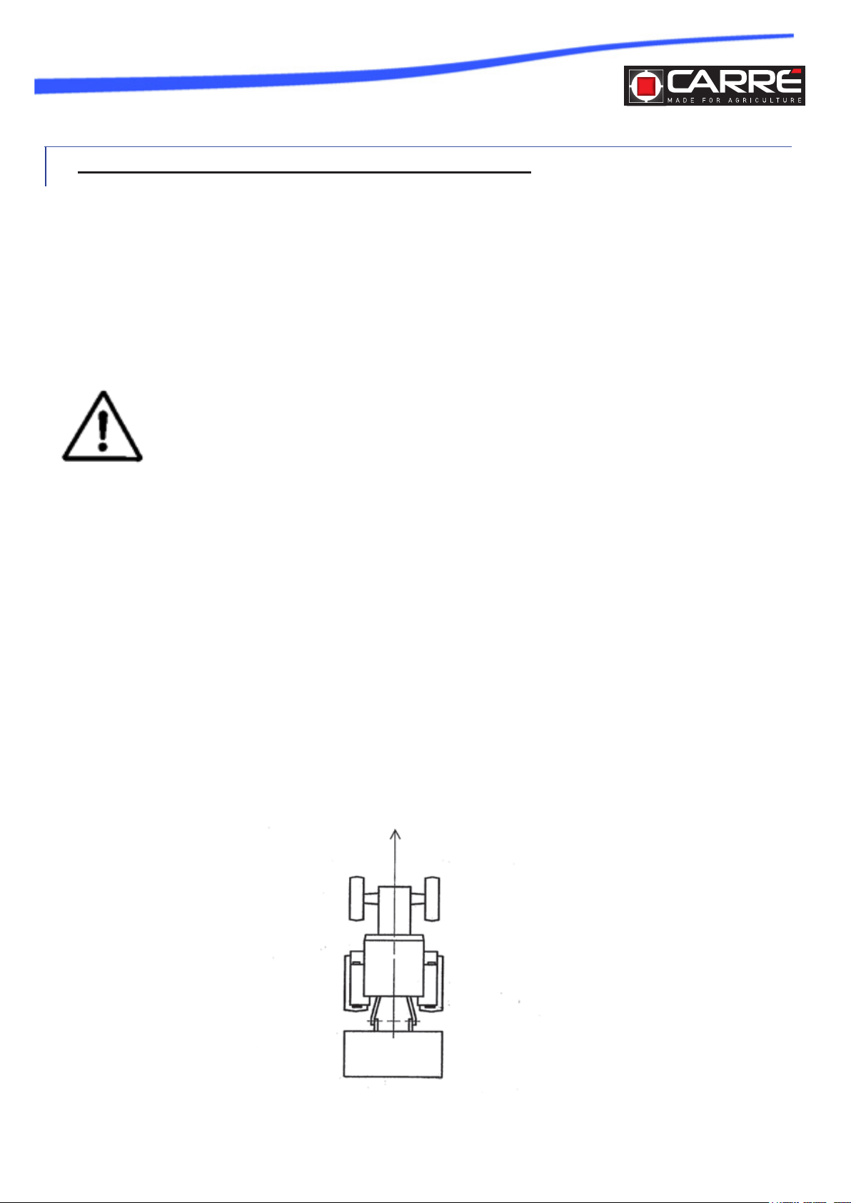
2.4 Direction of travel
The left side is the side located on the left of the user placed in the normal travel direction of the
machine forward.
The right side is the side on the right of the user placed in the normal direction of travel of the machine forward.
Direction of travel
Right sideLeft side
Page 5

3. INTENDED CONDITIONS OF USE
3.1 What is the use of the machine or equipment may be installed ont the
machine ?
This machine is intended to be used for routine farm work.
Any other use is considered contrary to the normal use and is therefore prohibited.
3.2 Operator qualications
The machine must be used, maintained and repaired by persons who are familiar with the particular
characteristics and who know the operational security modes correspondents.
Before using your machine , familiarize yourself with all the controls and use correct.
Ongoing work will be too late to do .
3.3 Dénition workstation
Never leave the driving position when the tractor (or the self-propelled machine ) is running.
No person shall be placed outside the dened workstations.
To access workstations , take the provision for access (ladder, step , etc.).
3.4 Environmental conditions
3.4.1 Working on slopes
Adapt your speed and driving style to land, roads and paths. Be vigilant and cautious !
In all circumstances , including in rough and steep terrain , driving at low speed machine especially
when cornering and avoid sudden changes of direction.
Do not stop or start suddenly up or down a slope.
3.4.2 Lighting , night work
Only operate your machine in daylight , otherwise use sufcient articial lighting ( contact your manufacturer or distributor) .
Page 6

3.5 Manufacturer & user responsibilities
Follow all installation instructions, operating settings,maintenance and repair in this manual .
Only use spare parts and accessories conform to the manufacturer ‘s recommendations.
Do not change yourself and do not change another person your machine and its accessories (
mechanical, electrical , hydraulic, pneumatic ) without
seek prior consent from the manufacturer.
Failure to comply with these rules can make your machine dangerous . In case of damage or
injury , product liability will be completely cleared.
4. GENERAL SAFETY RULES
4.1 Generalities
The other chapters of the instructions provide additional information that you also respect for your
safety.
Remember that vigilance and caution are the best assets of your safety.
Regulations and rules of prevention against accidents and safety related to occupational health,
protection of the environment and trafc must be observed at all times.
Make sure that no people, animals and no obstacle is not closed to the machine before starting and
during operation.
Keep children away permanently from the machine.
Never carry passengers on the machine OR Do not carry passengers by using seats provided for
this purpose, in accordance with current regulations.
Do not walk on the hoods or in any other place of the machine, except the areas provided for this
purpose (ladder, platform, means of access to the workstation)
Before working on the machine, ensure that it can not be started accidentally.
All remote commands (rope, cable, rod, exible, etc.) must be placed in designated areas so that
they may accidentally trigger a risk of generating operation of accident or damage.
Before use, check the tightening of screws, nuts and ttings. Tighten if necessary.
Before use, after each adjustment and maintenance, ensure that all devices protection are in place
and in good condition, and that their locks are engaged.
Make sure the plot (or lawn, etc.) has no unevenness and debris (wood, scrap metal, plastics, fence,
etc.) that can be thrown by the machine or damage it.
Do not wear loose clothing, long hair and jewelry and free that might be caught or trapped by elements of the machine in motion.
Never put hands, arms or feet moving parts, even at low speed. Keep your vis-à-vis animated elements distances.
When you hear a sound or feel unusual vibrations, stop the operation of the machine, look for and
eliminate the cause of the incident before returning to work. Call your dealer if necessary.
Page 7
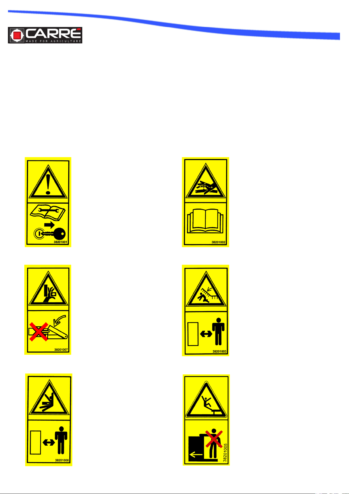
4.2 Warning & pictograms
Warnings and symbols afxed to the machine provide information on the security measures to
strictly observe and help prevent accidents.
Make sure that the warnings and pictograms remain clean and clearly visible. If damaged , have
new decals to your manufacturer (or distributor).
For repairs , ensure that spare parts have the same stickers as the original parts.
Read the maintenance manual and the
safety instructions before starting up.
Before any intervention, turn off the
tractor engine and remove the ignition
key.
Never put your hands in hazardous
areas while the parts are moving.
There is a danger of trapping your
hands.
To prevent leaks from the hydraulic
circuit, adhere to the instructions in
the maintenance manual.
People should be kept away from
the danger zone. There is a risk they
may be run over.
People should be kept away from
the danger zone. There is a risk they
may be run over.
Page 8
Do not go up on the step during the
moving of the machine.

Maintain in place the protection crankcase of the training belt of the seed
drill to protect your hands.
Be CAREFUL ! Risk of collision of
the wheels durng the folding against
hte tractor.
After the rst hour of work, tighten the
bolts.
Vibrations can loosen the bolt assembly.
To prevent eye injuries , do not look
directly into the area of service radar
sensor.
4.3 Toxic products
It is advisable to have at hand a rst aid kit .
Avoid contact with skin, eyes and mouth products such as fuels, oils ,
solvents, antifreeze and cleaning products . Most of them contain substances harmful to your health.
In case of incident , consult a doctor .
Please observe the indications on the safety labels containers of toxic products .
Batteries contain sulfuric acid. In case of skin contact , rinse
plenty of water and consult a doctor.
The pressurized hydraulic uid that escapes can have sufcient force to penetrate the skin and
cause serious injury . In case of contact with the body, see a doctor immediately .
4.4 Blockages
4.4.1 If the jam persists
Stop the engine, remove the ignition key or disconnect the battery (or the power outlet
electric).
Put the gear lever into neutral.
Apply the parking brake
Disengage the PTO .
Disengage the machine drive mechanism
Disconnect the hydraulic hoses.
Wait until all moving parts have completely stopped .
Lower / reassemble the machine
Fit the stabilization systems ( shims , stand, etc.).
Page 9

4.5 Fires
4.5.1 Preventive measures, warning against ammables
To avoid risk of re:
• make sure to keep the machine and its own accessories ;
• hold the (names of machine elements ) cleared of grass, leaves or excess grease .
Handle fuel with care. It is highly ammable, and its vapors are explosive .
Never store fuel container and the machine the tank still contains fuel in a building where fumes may
reach a ame or spark .
Never ll the fuel tank inside a building. Do not smoke while lling.
Never remove the fuel tank cap or add fuel in the tank when the engine is running ( or hot).
4.5.2 Fight against re
In any situation of re, use common sense and do the best to control it.
OR
Move away immediately from the machine and make sure that no one is near it.
4.6 Overhead power lines
Make sure that the clearance from the machine is sufcient in all cases of use of the machine ( eg
with open bonnets ) .
Consider also the radio antenna or other original accessory or retrotted and that changes the
height of the machine .
In case of contact of the machine with a power line , immediately stop the movement of the machine, its engine and engage the parking brake .
Check if you can leave your current position without touching the electric cables, then
jump your way that there is no position of simultaneous contact of your body with the machine and
the ground for your release .
Do not touch the machine until power lines are de-energized .
For anyone who approach the machine warn not to touch the machine and request that the power
line is switched off .
Page 10

4.7 Hitch / Tow
4.7.1 Generalities
The hitch of the tractor must be done on the hitch points provided for this purpose.
Ensure compatibility of the machine with the tractor (minimum motor power, hitch type, characteristics of the PTO of the tractor, etc.).
Do not stand between the tractor and the machine without turning the gear lever in neutral, close the
tractor parking brake and the machine disconnected PTO.
Do not stand between the tractor and the machine during a maneuver of the tractor, that it is controlled from the cab or from outside the tractor.
For maneuvers, select the forward speed of the tractor as small as possible.
When coupling, place the controls of the tractor so that it can not move during handling.
Once hitched machine, the towing device must be locked. Check the lock and the state of the hitch
before traveling.
Make sure the hitch of the machine causes neither overloaded nor bad weight distribution on the
tractor that could undermine stability:
• Do not exceed the maximum permissible load in tow points.
• Establish, if necessary, ballast weights on the supports provided for this purpose
according to the tractor manufacturer’s instructions.
When attaching or removing the machine, be sure to place all the support equipment and stability in
their respective places (on machines so equipped) to avoid imbalance of the machine.
4.7.2 Especially if towing a machine the lower lift arms : Hitch «two points»
Hitch the machine to a tractor whose lifting is equipped with lateral and vertical locking devices .
To travel on the road , observe the specied coupling height in the instructions for use and lock the
lift .
4.8 PTO / transmission Cardan shaft
4.8.1 Security linked to the tractor PTO and the machine shaft receiver
Check before operation that the speed and direction of rotation of the tractor PTO is compatible with
the intended use of the machine.
Check that power safety plugs are in place and in good condition. replace immediately if damaged .
Do not engage the PTO of the tractor when the engine is stopped.
Disengage the PTO when the angular limit of the transmission shaft may be achieved , eg by turning,
going up or down .
Any contact of the cardan shaft on the tractor or the machine can cause damage.
Page 11
4.8.2 Safety related to transmission shafts with universal joints
Only use the PTO shaft supplied with the machine or recommended by your manufacturer.
Ensure the proper collection tubes of the universal drive shafts , both in the working position in transport position .
Follow the safety instructions of the manufacturer of the transmission drive shaft .
Before connecting or disconnecting a transmission shaft PTO , disengage the PTO , stop the engine
and remove the ignition key.
Make sure before each use that the universal drive shaft is in good condition and is mounted and locked correctly.
Make sure the protector of the driveshaft is still in place and undamaged . Immediately replace if damaged .
After disconnecting the universal drive shaft to the PTO of the tractor , the latter must be covered with
a protective cap.
4.9 Maintenance & repair
Torques depending on the class of quality screws and nuts
Thread -
8.8 10.9 12.9
M8 24 33 40
M10 47 65 79
M12 81 114 136
M14 128 181 217
M16 197 277 333
M18 275 386 463
M20 385 541 649
M22 518 728 874
M24 665 935 1120
4.9.1 Generalities
The maintenance and repairs must be performed by qualied persons.
Always keep the machine and its accessories in perfect condition.
Be sure to clean oil and fuel tanks .
Observe the maintenance intervals .
Before working :
Stop the engine, remove the ignition key or disconnect the battery (or the electrical outlet ) .
Put the gear lever into neutral.
Apply the parking brake .
Disengage the PTO .
Disengage the machine drive mechanism
Disconnect such hydraulic hoses.
Wait until all moving parts have completely stopped .
Lower / reassemble the machine.
Fit the stabilization systems ( shims , stand, etc.).
Let cool the engine, the transmission housing , the angle gear ... the machine.
Page 12

4.9.2 Welding operations
During welding operations on the machine ( or tractor) , disconnect the battery ( or the electrical outlet ) and protect the pipes (especially rubber ) to prevent them from being damaged by incandescent
projections that could cause loss of oil , hydraulic uid , coolant , etc.
4.9.3 Interventions on tires
Do not work on tires unless you have the special tools and the necessary experience. Incorrect ins-
tallation can seriously compromise your safety. When in doubt, call a qualied staff.
The tire assembly of characteristics different from those recommended by the manufacturer is prohibited.
4.9.4 Electrical work
Before starting work on the electrical system , disconnect the battery ( or the electrical outlet ) .
4.9.5 Hydraulic interventions
Before working on the hydraulic system , make sure that the installation is not under pressure. Eliminate the pressure before disconnecting hydraulic lines .
The hydropneumatic accumulator is a gas pressure apparatus. It is forbidden to change its appearance
by machining, welding, grinding, drilling or any other means.
The hydropneumatic accumulator and its attachment must be constantly maintained in good condition.
All precautions must be taken to never exceed the maximum allowable pressure for the accumulator
After checking or adjustment, it shall show no gas leak.
Before restoring pressure in the hydraulic lines , make sure all connections are tightened.
4.9.6 Repairs
Eliminate or to remove any failure that could compromise security.
Immediately repair any leak or incident of the hydraulic circuit and the cooling circuit of the machine.
Do not look for a hydraulic oil leak (under pressure) with the ngers.
Guards and defective or damaged locks must be replaced immediately. No protective originally xed
on the machine must be removed or modied.
The hoses must not come from pipes that have already been used in a circuit.
Gas tubes shall show no welding. When a exible or rigid pipe is damaged, it must be replaced
immediately.
Repairs affecting under pressure or tension (springs , accumulators , etc. ) use of procedures and
specic tools . They should only be performed by a qualied person .
Page 13

5. ENVIRONMENTAL PROTECTION
5.1Storage and disposal (pollutants )
5.1.1 Pollution of land
Be careful not to spill on the oor and not to throw waste into drains fats and substances such as
engine oil, hydraulic oil, coolant, brake uid, fuel, etc.
Do not mix fuel and oils.
The user’s attention should be drawn to the risk of serious pollution by disposal of waste oils. This
concerns in particular used engine oils and transmission systems, as well as lubricating oils, mineral
oils used for hydraulic systems used oil must be collected and stored by avoiding mixing with water
or any other waste not oily. They should be stored in airtight facilities until their collection or their
treatment.
Collect the draining of liquids in sealed containers, clean and provided for this purpose.
It is prohibited to store, to give up, to le in the natural environment or burning outdoors tires. Rapportez- them to a distributor or an authorized collector.
In the absence of specic EU directive, different arrangements may exist in other Member States.
5.1.2 Air pollution
Do not open an air conditioning circuit ( contains gases that should not be released into the atmosphere). Only your manufacturer (or distributor ) may empty , recharge an air conditioning system and
recover the polluting gases.
5.2 Machines for the application of pesticides
When mixing , keep the product manufacturer ‘s instructions
precisely determine the amount of product needed to avoid late boiled scraps of treatment.
When the product container is empty, rinse it thoroughly eg by rinsing device .
Intervene when weather conditions are favorable, early morning or late afternoon .
Select a slow forward speed and low pressure spray to avoid losses due to drift .
Page 14

6. COMMISSIONING AND OPERATION
6.1 Environmental conditions
If you must do when you start your machine in a room , make sure ventilation
sufcient local . ( The engine exhaust contains poisonous CO).
7. TRANSPORT / MOVING
7.1 Trafc on roads open to the public
Before embarking on the highway :
• Place the transport position wash according to the explanatory note ;
• check the correct operation of the brakes;
• ensure the proper implementation , cleanliness and proper functioning devices
signaling and lighting provided ( lights, reectors , etc.).
On public roads , observe the provisions of the Highway Code :
• Respect the maximum size (width, length ) allowed. If exceeded the maximum size , comply with
regulations for exceptional transport.
• Respect the speed limit
Page 15

• CALCULATION OF DISTRIBUTION OF EXPENSES
LOAD FRONT AXLE TRACTOR SHALL BE EQUAL AT LEAST 20% OF
WEIGHT EMPTY THE TRACTOR
To check these values , follow these steps to
perform the calculation:
tractor control
- To check :
• The total weight allowed.
• The loads permitted axle.
• The supported load the coupling point of the
tractor.
• The permissible load capacity of the tires
mounted on the tractor.
• Is it permissible coupling load enough?
All gures on the registration card or on the
rating plate and in the tractor manual .
Values to be aware :
P (Kg) empty weight of the tractor
P2 (Kg) load on the rear axle of the tractor empty
M2 (Kg ) Total weight behind machine
M1 (Kg) Total weight of ballast in the front
(M ) Distance between the ballast center of
a
front and center of the front axle
b (M ) Wheelbase of tractor
c
d
(M ) Distance between the axis and the lower
hitching center of the rear axle
(M ) Distance between the axis and the lower
hitching the machine center of gravity
gravity
Consult instructions for use or registration card
Consult the specications of the
Consult the technical characteristics of
tractor and the front ballast , or measure .
Consult instructions for use or registration card
tractor, or measure
Consult the specications of the
• M1 mini = Weighting calculation required up front to a minimum
• Pc= Calculation of the total weight of the unit ( tractor + Machine )
• P1c = Calculating the load on the front axle
• P2c = Calculating the load on the rear axle
tractor.P1 (Kg) load on the front axle of the tractor empty
machine.
machine.
Page 16
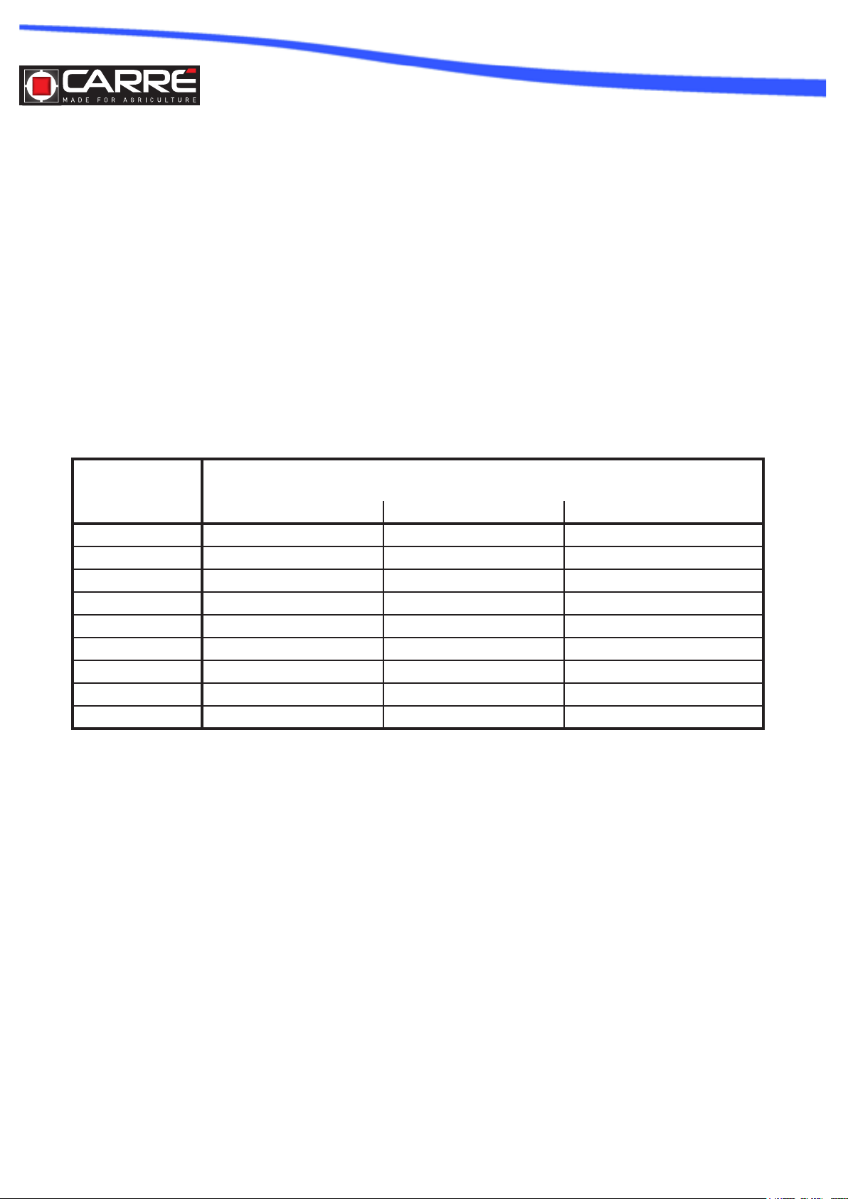
Complete the table below :
VALEURSCALCULEES
VALEURSAUTORISEESPARLE
VALEURSAUTORISESPARLES
PC
(Kg)
(Kg)
(Kg)
P1C
(Kg)
(Kg)
(Kg)
P2C
(Kg)
(Kg)
(Kg)
CALCULATED VALUES VALUE ALLOWED BY THE TRACTOR VALUES ALLOWED BY TIRES
TRACTEUR
FITTED TO THE TRACTOR
PNEUMATIQUESMONTESSURLE
TRACTEUR
- Check that:
• The calculated values must be <or = to the allowed values for the tractor and also by the tires
mounted on the tractor.
• It must be observed on the front axle of a tractor minimum load > or = 20 % of the load of the unladen tractor .
IT IS FORBIDDEN TO COUPLE THE MACHINE IS A TRACTOR:
• The calculated total load is > permissible value .
• The load on the front axle is < the minimum required.
Page 17

8. HANDLING
The handling of the machine will be done using the lifting eyes provided for this purpose , using a
hoist with a hook (crane, hoist , etc.).
Do not use the lifting eyes of the machine when lled .
When lifting the machine , be sure to keep away any other person and never be put under the lifted
machine .
9. HANDLING & REPAIR
9.1 Repair
Only use spare parts and accessories comply with the instructions in this document .
10. CLEANING
10.1 Cleaning Methods
Cover all openings to protect against the penetration of water, steam or cleaning products.
When using a high pressure hose , do not stand too close to the machine and avoid direct spray on
electronic organs, motor and electrical connections , hydraulic lines and hoses , seals, ller caps ,
etc.
10.2 Type cleaning products
Do not use harsh cleaning products ( chlorinated) .
Use rags that lint or soft brushes .
10.3 Controls the condition of the machine after cleaning
After cleaning, check the fuel lines , engine oil , brake and hydraulic oil and make sure they do not
leak , the connections are not loose and that show no deterioration.
Rectify immediately to deteriorations .
11. SPECIAL FEATURES OF THE MACHINES USED IN EXPLOSIVE
ATMOSPHERES
As part of an ATEX zone , the personnel must be aware of the risks
explosion and possibly have received specic ATEX training.
Page 18

FRONTAL HOPPER
Page 19

INDEX
1. TECHNICAL SPECIFICATIONS
1.1 Description
1.2 Implement components
1.3 Chart of technical data
1.4 Sound level
2. INSTALLATION
2.1 Transport
2.2 Lifting
2.3 Connecting the front hopper to the tractor
2.4 Radar installation
2.5 Connecting system between front hopper and rear distribution head
2.6 Check of the tractor stability and its lifting power
3. INSTRUCTIONS FOR USE
3.1 Operation of the blower
3.2 Distribution
3.3 Unhitching the front hopper
3.4 Unhitching the rear implement
4. MAINTENANCE
4.1 End of seasons operations
5. ACCESSORIES
5.1 Hopper extensions
Page 20

1. TECHNICAL SPECIFICATIONS
1.1 Description
• The seeder/fertilizer spreader mod. OCTOPUS must only be used for working agricultural lands.
Any other use differing from the one described in this manual can damage the machine and be dangerous for the operator.
• The seeder/fertilizer spreader mod. OCTOPUS can be used with other equipment for working the
soil, but only with the addition of a special assembly kit.
• The seeder/fertilizer spreader mod. OCTOPUS is ideal for sowing cereal: wheat, barley, rye, oats,
rice; ne seeds and fodder: rape, clover, alfalfa; and for big seeds: soya, peas.
• The seeder/fertilizer spreader mod. OCTOPUS is suited for the distribution of various types of fertilizers.
• The seeds are deposited in the soil by coulter organs, sock or discs, and are distributed continuously. A special
revolving metering unit driven by a wheel which adheres to the ground regulates the quantities to be
distributed.
• The seeds are distributed and transported to the coulters by compressed air that is produced by a
fan. The fan is
moved by the tractor power takeoff, or hydraulically as in the Plus version.
• The disc or sprint sock coulter is mounted on a super-elastic support that gives excellent depth and
pressure
control on the soil and regulates the height of the seed bar.
For the development and the construction of this implement the following guidelines of the Standard
98/37CE have been studied and applied:
UNI EN 14018
UNI EN 1553
UNI EN 982
ISO 11684
ISO 3757-2
The machine will work well if used correctly and if maintenance is carried out regularly. Users are
strongly advised to scrupulously observe the instructions given in this manual in order to prevent any
inconvenience that could impair good machine operation and its durability.
Users must follow the instructions given in this manual because the Manufacturer cannot be held
responsible for any damage or injury caused by negligence and the non-observance of such instructions.
The Manufacturer assures complete assistance with regard to immediate and accurate technical
service, a well as anything that may be necessary for a better operation and maximum performance
of the implement.
Page 21
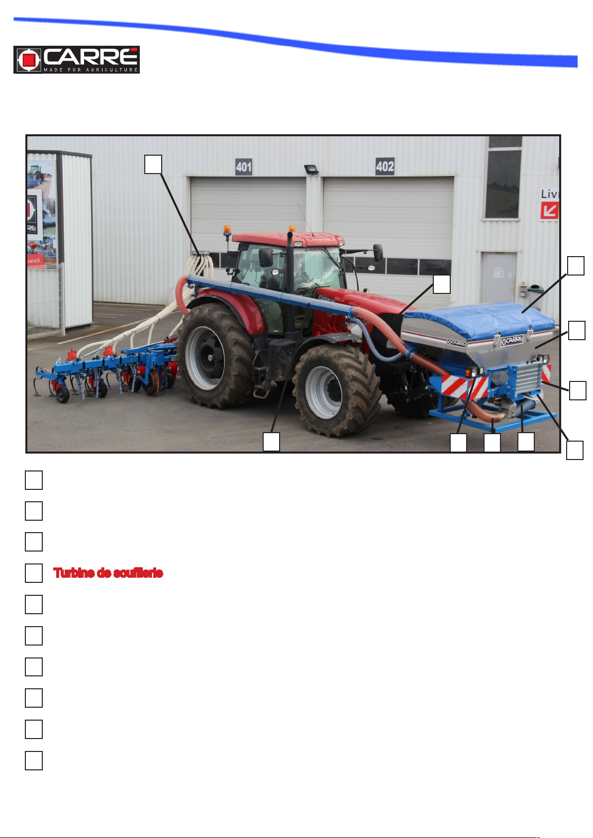
1.2 Implement component
10
7
8
1
2
Hopper
1
Ladder for lling lader
2
Front lights
3
Turbine de souferie
4
Metering unit
5
Radar
6
Closing cover
7
Seed conveying pipe
8
Seed conveying pipe
9
9
3
6
5
4
Distribution head
10
Page 22

1.3. Chart of technical data
MOD
6
OCTOPUS
250 cm
45-50 cm
70-80 cm
1400 ou 1800
L
600 ou 650 kg8
12
1.4. Sound level
If the tractor is equipped with a cabin, the sound level will depend on the soundproo-
ng level of the cabin itself. If the tractor does not have a cabin or is used with the
windows open, the noise level emitted by the machine while working and measured
at a distance of 200 mm. from the rear window exceeds 85 dBa. It is therefore advisable to use protective earmuffs as indicated in the regulations of different countries.
Page 23

2. INSTALLATION
2.1 Transport
The machine can easily be transported even over long distance with suitable means of transportation:
lorries, trailers, train cars etc.
The loading and unloading of the machine can be rather dangerous operations, unless they
are performed with the utmost care: have all unauthorized personnel leave the area; clear
and circumscribe the loading area; check that the available means of transportation are in
good working order and strong enough for the job at hand.
It is also necessary to make sure that the area of operation is free and that there is enough
escape space, i.e. a free and safe area where it is possible to move quickly should the machine fall down. Said operations are to be performed exclusively by personnel trained to perform this type
of work.
Before beginning the loading operation make sure that the available means is certied for this type of
transportation and that it is strong enough to support the weight of the machine. To this end see CHART
OF TECHNICAL DATA (see Par. 2.3) for the weight of the machine.
This chart is also useful to check the possibility of transit of the machine through narrow passages.
2.2 Lifting
The Lifting and moving operations must be performer with means
strong enough to carry the weight of the machine and by personnel trained in this type of work. If it becomes necessary to lift the
machine, hook the machine
as shown in the picture and move it: during this operation the
machine should not be lifted by more than 200 mm. from the ground. In order to
avoid damages to the hopper metal plates, use approved lifting belts
2.3 Connecting the front hopper to the tractor
This operation must be carried out on a horizontal surface, with the seed-drill in a stable
position on its support legs
The front hopper is supplied STANDARD with a cat. 2 hitch for tractors with front lifter.
When the hopper has been connected solidly to the tractor, make sure that the equipment
is perpendicular to the ground. If necessary, you can use the upper arm to correct the position of the
equipment.
Support the hopper with the tractor lift and lift the legs toward the tractor. Block them into position by
inserting the pin into the corresponding bushing (see pct. below)
Page 24

2.4 Radar installation
The radar is to be positioned as follows on the frame supporting the hopper:
1. Attach the support A to the lower frame of the hopper by means of the U-bolts clamps C
2. Attach the radar B to the support A.
There is only one possible position of the radar on its support, while the latter can be displaced along the slanted pipe of the frame, so as to guarantee, in the working position, a
height from the ground which can vary between 0.4 and 1m.
In order for the radar to work at its ideal position of ± 37° the hopper must be parallel to the grou nd
while it is working.
2.5 Connecting system between front hopper and rear distribution head
The seeder/fertilizer spreader OCTOPUS is
complete with a connecting system between the
front hopper(A) and the distribution head (B).
Such connection can be adjustable and must be
rmly attached to the tractor, so as to avoid loops
and to guarantee the correct performance of the
power or disc harrow when working up or downhill.
2.5.1 Main components
The connecting system consists of:
A. 2m long rigid PVC pipes
B. Supporting plates
C. Blocking rings
D. Connecting anges between the rigid and the
exible pipes
E. Different tightening elements
F. Connecting electric wires
B
A
Page 25

2.5.2 Installation of the connecting system on the tractor
When the seeder/fertilizer spreader is delivered, the system for connecting it to the tractor is not
assembled.
Its assembly is a task to be performed by the end user, who must perform said assembly depending
on his tractor and following the steps below:
1. Determine the length (L) from the possible ones: 3860, 3660, 3460 ,3260, 3060, 2860, 2660, 2460
2. Assemble the plates (B) on the length (L) and attach them rmly to the tractor
3. Insert in the receptacle (S) the wire extensions and keep the connection protruding by 10/15 cm
from their seats (M)
4. Pull out from their seats (U) the wires which will be connected with the tractor (es: monitor, battery)
calculating their necessary length
5. Coil possible exceeding lenghts of cables inside their receptacle (S)
6. Secure all the wires with plastic strips
7. Insert the pipes into each other (A) and cut a piece off the end to adjust to the length (L)
8. Place the pipes over the plates, assemble the anges (D) at the ends and secure them with the
fastening metal rings (C)
Page 26

2.5.3 Connecting the hopper with the implement
The operation is to be performed on a level surface, with the seeder/fertilizer spreader and the
implement rmly supported by their supporting stands.
The newly assembled connecting system can be left permanently attached to the tractor. It pres-
ents at its ends two quick hitching anges for the front hopper and the rear implement.
Once the hopper and the implement have been hitched to the tractor, connect them pneumatically and
electrically, following the steps illustrated below:
1. Connect the Ø130 mm seed-conveying pipe (A), already atta-
ched to the hopper with the front hitching ange of the connecting
system and secure it with an metal clamps.
2. Insert the Ø 60 mm pipe containing the electric wires (B), already attached to the hopper, into the lower hole of the front quick-
hitching ange and secure it with a metal clamp.
3. Connect the electric wires coming from the hopper with the respective extensions previously installed on the connecting system
(C)
4. Hitch the implement to the tractor.
5. Connect the seed-conveying Ø130 mm hose (D), coming from
the distribution head with the rear quick-hitching ange of the
connecting system and secure it with a metal clamp.
6. Connect the electric extensions of the connecting system with
the relevant wires of the electronic components installed on the
implement (E) and seure them with a plastic strip.
In order to use the tractor with other implements it is possible to unhitch the hopper and the implement,
from the tractor without removing the system for the connection with the tractor.
Page 27

2.6 Check of the tractor stability and its lifting power
When an implement is hitched to a tractor and, as far as circulating on public roads is concerned, it
becomes an integral part of it, it can alter its stability and make it difcult to drive it and to work.
When you add a machine to the tractor, you will change the weight distribution over the axles. It is therefore recommended to add suitable ballast to the front of the tractor, so as to distribute adequately the
weight over the axles.
Calculate the ballast to be used with the following formula:
CALCULATING TRACTOR STABILITY.
were:
i = inter-axle (m) of the tractor wheel
d = distance between the front axle and the front
ballast (m) s = projection of the implement from the
rear axle (m)
T = tractor mass (kg)
Z = ballast mass + hopper with seeds (Kg)
M = implement mass (Kg)
At least 20% of the total tractor-implement mass must
weigh on the front bridge of the tractor. It should be
remembered, however, that stability can be improved
with the right choice of tractorimplement combination
and with the application of ballast to the front, in the
limits and methods indicated by the tractor manufacturer. Moreover, when the tractor is stopped, the machine must be lowered to the ground, thereby improving stability.
Page 28

3. INSTRUCTIONS FOR USE
3.1 Operation of the blower
The implement is suited only for the use described. Any other use deferring from the
one described in this owner’s manual can damage the machine and be a hazard to the
user.
The good performance of the implement depends on its proper use and an adequate maintenance. It
is, therefore, advisable to follow closely the directions contained herein, so as to prevent any inconvenience which may impair the good performance and the life span of the machine. It is also important
to follow the directions contained in this owner’s manual, because the Manufacturer cannot be held
responsible for damages caused by negligence or the non-observance of the directions. The hydraulic system driving the air-pump must be used, serviced and repaired by personnel having a perfect
knowledge of the unit itself and of the hazards it may present. Check the correct plugging of the quick
couplings: unless they are correct, damages may occur to the components of the system. Only disconnect hydraulic connections after they have been de-pressurized.
The leaking of oil under pressure may cause skin wounds and severe infections.
Should this happen, consult a doctor immediately. It is absolutely forbidden to install
hydraulic components inside the tractor cab.
3.1.1Hydraulic connection with the tractor
Check in the Owner’s Manual of the tractor its hydraulic features, which must be as follows:
• Hydraulic system of the “CLOSED CENTER” (also called LOAD SENSING )type
• Pump with variable displacement
• Oil delivery exceeding 50l/min. the hydraulic operation requires 24 l/min.
• Working pressure: 100 ÷ 130 Bar Max 150 Bar (fan speed 4200÷4500 rpm, max 4600 rpm)
• Oil cooling: should the tractor not be equipped with an adequate cooling system it is necessary to install one
• The tractor must be suited to receive a free-return ow connector (NO COUNTERPRESSURE).
The oil ow necessary to drive the blower is taken from the tractor
hydraulic distributor, through a delivery hose 1⁄2 A.
The rotational speed of the hydraulic motor and, as a consequence, of
the suction unit depends on the ow pressure, which is shown on the
manometer.
The system is complete with a safety valve which makes it possible for
the device to keep on turning by inertia even after the system has been
shut off or a sudden break down of the system has occurred.
For a correct performance it is important to connect the ow discharge
hose 3⁄4 G of the hydraulic motor to a free ow discharge plug of the
tractor; this free discharge cannot present any counter-pressure exceeding 3 Bar.
This connection is of basic importance above all to protect the hydraulic
seals of the motor, which, if damaged, would allow very dangerous oil
leaks.
A) Quick coupling on the delivery side 1⁄2 B) Three-way electro-valve
C) Manometer
D) Motor
E) Free-ow discharge
F) Safety valve
G) Quick coupling on free-ow discharge 3⁄4 H) Flow-adjusting device
(option)
Page 29

3.1.2 Adjustment of the oil ow without a varaible displacement pump
If the tractor does not have a variable displacement pump, there is a special kit
for this purpose which is supplied on demand.
3.2 Distribution
The metering unit is the main element that makes the seed- drill work. It is
positioned under the seed hopper and
it is driven by the driving wheel through a mechanical chain transmission and
a universal joint.
The metering unit, which consists of a cylinder containing longitudinal hollow
sections A, distributes a certain quantity of seed - depending on the calibratio
The air ow generated by the fan blower D and regulated by the buttery
throttle E transports the seeds to the distributor head that can be found at
the end of the “Venturi” tube. From here, the seeds are taken to the coulters
and then sown.
The metering unit can work with seeds of between 1 and 10 mm. The main
seeds are:
• Cereal: wheat, barley, oats, rye, triticale, sorghum, rice
• Large seeds: corn, peas, beans, soya
• Small seeds: grass, clover, rape
3.3 Unhitching the front hopper
The unhitching of the hopper from the tractor can be a very hazardous operation. Use
estreme caution while performing the entire operation and follow directions strictly.
To unhitch the seed-drill correctly, you must work on a horizontal surface as follows:
• Lower to the ground the supporting stands and secure them rmly with the appropriate pins.
• Disconnect all hydraulic and electric connectors supplying the seeder/fertilizer spreader
• Remove the conveying corrugated hose from the connecting system
• Unhitch the hopper from the tractor and make sure it remains in a stable position
3.4 Unhitching the rear implement
The unhitching of the disc or power harrow from the tractor can be a very hazardous
operation. Use estreme caution while performing the entire operation and follow
directions strictly.
To unhitch disc or power harrow correctly, you must work on a horizontal surface as follows:
• Lower to the ground the supporting stands and secure them rmly with the appropriate pins.
• Disconnect all hydraulic and electric connectors supplying the seeder/fertilizer spreader
• Remove the conveying corrugated hose from the connecting system
• Unhitch the hopper from the tractor and make sure it remains in a stable position
Page 30

4. END OF SEASON OPERATIONS
4.1 Remisage
At the end of the season, or if you believe that you will not use the machine for a long period of
time, the following operations should be carried out in order to maintain its integrity:
Carefully remove all the seeds from the hopper and the distribution organs.
Wash the machine with plenty of water, especially the hoppers, then dry it. While doing this keep
ap B open (gure above) and remove the connection bend to the Venturi. Do not use a water
cleaner.
Leave ap B open (gure above) to protect against mice that can damage the machine.
Carefully check and, if necessary, replace any worn or damaged parts
Tighten all screws and bolts
Protect all unpainted parts with lubricant
Cover the machine to protect it
5. ACCESSORIES
5.1 Hopper extension
The hopper extension increases the hopper capacity from a basic 1400 litres to 1800 litres (+400
lit).
Page 31

DOSEUR
Page 32

INDEX
1. TECHNICAL SPECIFICATIONS
1.1 Description
2. SETTINGS FOR SEED DRILLING
2.1 Seeding chart
2.2 Reading the chart
2.3 Adjustment of the metering unit
3. CALIBRATION TEST
3.1 Electrical calibration test
4. CLEANING
4.1 Discharging the seeds
Page 33

1. TECHNICAL SPECIFICATIONS
1.1. Description
The metering unit, the main element for the performance of the seed-drill, is positioned under the
seed hopper and it can work with seeds
measuring from 1 to 10 mm.
The main elements which constitute it
are:
1. Gears for the selection of normal to
ne seeds
2. Lever for the adjustment of the seed
quantity
3. Sticker with graduated scale
4. Indicator of seed quantity
5. Brush for cleaning the alveolar rotor
6. Lever controlling the shutter to
quickly empty the metering unit/hopper
7. Knobs for the quick removal of the
bottom wall
8. Snap pin for normal/ne seeds
9. Slide for calibration test
10. Venturi element
11. Lever for calibration test
12. Flap for discharging seeds out of
the Venturi element
2.SETTINGS FOR SEED-DRILLING
For each type of seed to be drilled it is necessary to adjust the metering unit very precisely
following the indications concerning the main seed types listed in the SEEDING CHART
Depending on whether you need to drill ne or normal seeds the metering unit needs to be
adjusted as indicated in the seeding chart
It is obvious that the F position is meant for Fine seeds, while the N position is meant for Normal
seeds.
Page 34

2.1 Tableau de semis
Page 35

2.2 Reading the chart
When reading the chart, follow the procedure described below:
1. In the chart identify the type of seed you want to drill
2. Set the metering unit on the normal seed N position or on the ne seed F (see chap.3.4).
The position is indicated in the chart and it relates to the type of seed
3. Choose the quantity of seed you want to drill (Kg/ha)
4. By matching the line of the quantity to be drilled with the column of the position (normal or
ne seeds) you will identify the degree of opening of the alveolar rotor of the metering unit
5. Adjust the metering unit on the resulting datum (see chap. 3.4)
Page 36

2.3 Adjustment of the metering unit
In order to dispense all types of seeds, the metering unit must undergo three different adjustments :
A. By properly moving the highlighted gear you can
obtain two different rotation speeds of the alveolar
rotor (chap. 3.4.1)
B. Through the highlighted handle, which is complete
with a blocking pin, you obtain the proper volume of
seeds to be distributed directly in the alveolar rotor
(chap. 3.4.2).
C. With the snap pin you change the position in the
metering unit: either NORMAL or FINE seeds (chap.
In order to prevent damages to the metering unit, decrease the quantity of seed
only when it is rotating or when the hopper is empty
2.3.1 Rotation speed
The rotation speed is chosen by moving the 2
gears along the shaft:
RED = Fine seeds BLACK= Medium seeds
In order to do this, it is necessary to overcome
a small resistance to bring them to the desired
position: a click will signal that this position has
been reached.
Before you perform this movement, make sure
that the cogs of the gears are aligned by rotating
one of the two shafts.
2.3.2 Seed quantity
The index on the graduated sticker can be made to slide by turning the crank handle and it determines the quantity of seed to be distributed.
The sticker is divided into two sections:
- from 0 to 30 for ne seeds F
- from 0 to 130 for normal seeds N
Page 37

2.3.3 Normal seed/Fine seed positions
The heart of the metering unit consists of the alveolar rotor which is
divided into 2 sections: ne seeds F and normal seeds N.
To obtain the setting for normal or for ne seeds it is necessary to
bring the index to the “0” position on the graduated sticker. This must
be done with the metering unit empty and clean. Then insert the snap
pin in the correct position
f you set the metering unit for normal seeds, remove the revolving cleaning brush,
because it is only necessary to clean and empty the alveolar rotor from ne seeds
To assemble or remove the revolving brush, all you need to
do is to loosen the knobs for the quick removal and remove
the bottom plate of the metering unit.
This will make the inside of the metering unit accessible to
perform this operation
Page 38

3.CALIBRATION TEST
Before lling the hopper for the rst time, open ap A in order to remove possible foreign
bodies which may be present. When lling the hopper always make sure that foreign objects
(nylon, paper, strings etc.) do no enter.
Once the metering unit has been properly set, it is necessary to perform a calibration test, since the data in the chart are
merely indicative, due to the differences in size, humidity content
and specic weight of the seeds.
With the empty hopper completely empty, shut the alveolar rotor
with the C crank handle.
Introduce a small quantity of seeds (at least for 2/10th of an hectare) into the hopper.
From the chart calculate the opening degree of the alveolar rotor
based on the type and quantity of seed to be distributed, by turning
the crank handle C and making it coincide with the number in the
graduated sticker D.
Through the lever E on the Venturi element open the shutter, then
place a container under the slide B to collect the seeds
Depending on the composition of your seed-drill, there are 2
methods for performing the calibration test
- mechanical calibration test - electrical calibration test
Bulkhead F allows for a precise sawing test.
Remove Bulkhead F and perform the sawing test under the Venturi by opening only the G door in case of large quantities To be
sawn as avoiding to doing so might provide wrong results.
Page 39

3.1 Electrical calibration test
With your monitor ON press the push button for the calibration test and hold it down for the period of
time necessary to sufciently ll the container. Weigh the collected seeds and store the net weight in the
monitor.
Do not shut the alveolar rotor with seeds inside the metering unit; these would damage the metering
elements.
The data in the chart are indicative, since the specic weight, the humidity content and the size of the
seeds often vary. Therefore, it is advisable to perform yet another calibration test, just to be sure: the
quantity measured with this latter test will then be the constant weight distributed.
4.CLEANING
At the end of the season or whenever you foresee that the seed drill will be idle for a long period of time,
it is mandatory to discharge all the residual seeds from the hopper and the distribution elements and to
4.1 Discharging the seeds
The discharge of the seeds is done in 2 steps:
- Emptying the hopper
- Completely emptying the metering unit
- Emptying of the Venturi element
4.1.1 Emptying the hopper
To discharge the seeds from the hopper open the ap
at the bottom of the metering unit and place a container underneath to collect the seeds.
Page 40

4.1.2 Completely emptying the metering unit
When emptying the hopper, some residual seeds will remain inside the metering unit. It is highly advisable to remove them, since they may sprout and damage the metering components.
In order to perform a thorough cleaning, remove the knobs A and remove plate B. Now the inside of
the metering unit is accessible. Turn the alveolar rotor to remove possible residues from the cells C.
4.1.3 Emptying the venturi element
After the removal of the seeds from the metering unit, open
the ap B at the bottom of the Venturi element by acting on
the shutting catch A, then remove possible seed residue from
the bottom of the element
At the end of these operations wash the hopper and the transmission organs with water. Dry thoroughly. Check that no part is damaged: should there be any damaged part, replace it and protect the
unvarnished metal parts with lubricants.
It will be in your best interest to nd the machine ready to be used the next time you need it.
Page 41

COMPUTER
Page 42

INDEX
1. GENERAL INFORMATION
1.1 Purpose of the owner’s manual
1.2 Warranty
2. TECHNICAL SPECIFICATIONS
2.1 General description
2.2 Installation of the computer
3. INSTALLATION
3.1 Electric wiring
3.2 Installation of the sensor of the distribution fan «t»
3.3 Instalaltion of the sensor of the product level indicator «n°1»
3.4 Installation of the «x» lifting position sensor
4. FUNCTION
4.1 Description of the control panel
4.2 Status indicator
4.3 Use of the monitor keys
4.4 List of screen shots
4.5 Description of the main screen shot («main»)
5. PROGRAMMING
5.1 Menu for tramline programming
5.2 Programming menu for the forward speed sensor
5.3 Radar automatic calibration
5.4 Set simulated forward speed
5.5 Programming menu for the seed drill width
5.6 Programming menu for the manual adjustment of the calibration rate
5.7 Programming menu for the calibration test from the monitor
5.8 Programming menu of fan/seed level alarms
5.9 Menu for the operator’s conguration
5.10 Calibration test through the switch on the machine
6. DIAGNOSTIC
6.1. Diagnostic instrument
6.2 Diagnostic - metering unit
6.3 DIagnostic hystory
7. MAINTENANCE
7.1 Normal maintenance
Page 43

1. GENERAL INFORMATIONS
1.1. But de la notice d’utilisation
This Owner’s Manual has been written by the manufacturer of the machine and it is an integral
part of the documents accompanying the machine.
This Owner’s Manual denes the purposes for which the machine has been manufactured, specifying its correct
use and the limits of the same.
The punctual application of the data contained in the present Owner’s Manual guarantees the safety of the persons using the machine, economy of operation and a longer lifespan of the machine.
The present Owner’s Manual has been divided into different paragraphs in order to make the
search for the various items and the consultation of the initial index easier.
The pictures included in this Owner’s Manual are supplied by way of information only. Even if they
greatly differ from your machine, the safety rules and the information are always guaranteed at any
rate.
1.2. Warranty
At the time of delivery, check whether the machine has been damaged in transit and if all the
accessories are present.
Possible claims must be made in writing within 6 days.
INVALIDATION OF THE WARRANTY
The warranty becomes immediately void:
-if damage is caused by an incorrect maneuver
-in case the instructions given in this manual have not been strictly followed
-if non-original parts have been used
-if modications have been made to the machine without the consent of the Manufacturer.
-if a damage has been caused accidentally
-if the damage has been caused by events of force majeure (lightening, oods, re or other independent causes)
Page 44

2.TECNICAL SPECIFICATIONS
2.1.General description
The multi-function electronic computer of the “ALPETRONIC Super Plus” series has been designed for agricultural, pneumatic row-seeding seed-drills
Alpetronic Super Plus has been designed to automatically and continuously monitor the quantity
of seed distributed by the seed-drill. With the machine in operation and depending on the soil
conditions, it is possible to increase or decrease the normally pre-set seed ow
This computer can manage and monitor the following functions:
• Tramline : it automatically shuts off some of the rows to obtain a non-seeded track to be used as
a “road” for
the subsequent operation with a sprayer.
• Pre-start : it allows the start of the seed metering unit while the machine is idle, in order to guarantee a
precise drilling when the seed-drill work is resumed. It displays and checks the following data:
• Driving speed recorded by radar (Km/h).
• Number of hectares seeded, through two independent totalizators (partial and total)
• Quantity in kg of seed distributed through two independent totalizators (partial and total)
• Total number of hours worked (cannot be reset)
• Number of hectares seeded (cannot be reset)
• Seed-level in rear hopper
• RPM of distributor fan
2.2.Installation of the computer
To install the computer proceed as follows:
• On a at surface inside the cabin of the tractor bore two holes (D. 8 mm) at the same distance as
the holes which are present in the holding bracket (ref. A), then attach the bracket to the frame of
the tractor through
We suggest that you install the computer right in front of the operator in order to Make its use
easier during the working cycle.
Page 45

3.INSTALLATION
3.1 Electric wiring
Connect cable A directly with the tractor battery. Be careful to connect the poles correctly (brown +
/ blue -) and wire the cable correctly to the tractor.
From time to time check the voltage of the tractor battery, since the electric part
of this instrument requires a constant 12 volt supply. If the power is lower it may
cause malfunctions. (go to the page “Diagnostic) and select “Instrument”: this will
show the voltage of the battery
• Connect the connectors of cable A to the connector of cable B
• Fix the monitor inside the cabin
• Connect cable C with cable D and fasten the 2 connectors tightly.
Page 46

3.2. Installation of the sensor of the distribution fan “T”
3.2.1. Hydraulic version
The sensor for the reading of the fan “T” RPM must be installed on the
proper bracket (A), which, in turn, must be attached to the fan support
(B) perpendicular to the rotating shaft, at a distance of 2 /3 mm. from
the magnetic reference (C). The sensor will read the passage of insert
C.
Page 47

3.3. Installation of the sensor of the product-level indicator “N1”
The capacitive sensor recording the product level must be positioned so as to record the level of the
product in the hopper when it drops below the reserve limit; it is positioned inside the hopper and
mounted on the frame. It is important for the head of the capacitive sensor to be directly in touch with
the product: thus, when the sensor is covered by the product it issues no alarm signal, but when the
seed drill is in operation and the sensor head is uncovered, the relevant alarm signal is activated.
3.4. Installation of the “X” lifting position sensor
This sensor must be installed with its relevant elements and must be
adjusted so as to record the changing position of the implement from
its working to its lifted position.
For the assembly details see the special manual concerning the
component S31155 (cod.D13007).
Page 48

4.FUNCTION
4.1 Description of the control panel
All the functions of the instrument are accessible through FIVE menu keys below the LCD computer
screen. Picture 1
A few seconds after pressing the ON / OFF key (Ref A) the main screen shot “MAIN” will appear, then,
by pressing again the key you will have access to the screen shots: “RATE” “INFO” and programming
menu.
The key in the middle (Ref B) makes it possible to:
1. Activate the manual Pre-start (see par..4.5.4)
2. Increase the percentage of the seed quantity (see par. 4.6)
3. Scroll the various Menus and enter the values and the parameters
The three keys under the LCD screen Ref C control various functions in the main screen ( for instance:
blocking the rotation of the electric motor , blocking the Tramline) and in the programming menus they
are used to select and enter several parameters. The texts and the icons are displayed at the side of the
keys to indicate their functions
To turn off the instrument press for more than 5 seconds
4.2 Status indicator
On the upper section of the display and in all the screen shots there is a bar showing the time but also
all the icons. Said icons indicate:
MARCHE
ARRÊT
Page 49

4.3 Use of the monitor keys
Page 50

4.4 List of the sreen shots
Once the monitor has been turned on, each time you press the key, you will enter a different page
Indicator of the screen shot
number
Page 51

Page 52

4.5 Description of the main screen shot (“MAIN”)
Whenever the computer is switched on the main screen shot (“MAIN”) will be accessed directly. This
screen shot is divided into 5 sections which display the following functions
Screen shot with the machine not in operation
Page 53

4.5.1 Forwards speed & alarms
With the exception of sudden speed variations, the forward speed displayed at any given moment will
be the average speed calculated every 3 seconds.
The instrument is programmed to set off a «low speed» & a «high speed» alarm
If the seed drill is working at
a forward speed of less than
0.5 Km/h an alarm will blink
on the main screen shot (see
picture at the right), at the
same time an acoustic alarm
will be set off. At any rate the
minimum speed value can be
altered at the discretion of the
end-user. (see par. 4.3)
If the seed drill is working at
a speed exceeding the speed
calculated and permitted by
the computer (indicated in the
main screen shot “RATE”) an
alarm will blink on the main
screen shot (see picture at
the right), at the same time an
acoustic alarm will be set off.
Page 54

When a new seed quantity to be distributed is inserted in the RATE screen
shot, the instrument will re-calculate and display the maximum speed at which
the new quantity can be maintained.
Said calculation takes the following data into consideration :
- New quantity of seed to be distributed
- Working width
- Calibration rate (calculated by the instrument with the calibration routine)
- Reduction rate of the electric motor
Maximum RPM of the electric motor
Press key to go back to the “RATE” screen shot .
N.B: If the forward speed is too low, the operator must modify (increase)
the opening of the metering unit and perform the calibration routine again to
increase the calibration rate.
4.5.2 Tramline status / Functions
The main screen shot “MAIN” will display the tramline “status”
TRAMLINE RHYTHM
INCREASE OF NUMBER OF BOUTS
The tramline rhythm does not always begin at bout “1”; check programming carefully (see par. 5.1) The increase of the number of bouts is
determined by the lifting of the machine until the tie-rod of the upper arm
of the tractor lift activates a micro-switch which is present on the top link
of the 3-point hitch of the machine.
The pin of the micro-switch must always be positioned below the
top link of the 3-point hitch.
Page 55

The bracket must be adjusted (see picture at the right) so that while in the working position - the pin of the micro-switch never
comes in touch with the top link of the 3-point hitch and when
the machine is lifted the pin is tilted.
Pay special attention to and take particular care of this micro- switch. NEVER
TEMPER WITH IT FOR ANY REASON,
since it would jeopardize the function of
the metering system control.
If necessary press key +1 to change & obtain the correct number of the bout: for instance, if while
working it becomes necessary to lift the machine in order to avoid an obstacle, the +1 key is used to
go back to the initial working bout.
HOLDING THE TRAMLINE BOUT NUMBER
Press key in order to hold the current tramline bout number. This is a very useful function
when it becomes necessary to perform unforeseen maneuvers during the working process.
The icon indicates that the bout number is being held. Press the key under this icon to activate the relevant tramline bout number again
4.5.3. Manual control of the metering unit rotation
With the fan in full operation/ and after the forward speed has been registered by pressing the key
under the con it is possible to stop the rotation of the metering unit.
This function is useful when the soil needs to be cultivated further, without, however, being seeded .
By pressing the key under the icon or the second
time the rotation of the metering unit controlled by the radar
and by the micro-switch which is on the top link of the machine is resumed
Whenever the seed drill is lifted off the ground the rota-
tion of the metering unit is stopped thanks to the action
of the micro-switch which is located on the top link of
the 3-point hitch.
Page 56

4.5.4. Fonction pré-start (manuelle)
La fonction de pré-démarrage aide à éviter les zones non semées notamment dans les coins de
champs. Cela démarre le doseur à la vitesse de calibrage pendant que le semoir est toujours à l’arrêt,
et ainsi amorce le semoir jusqu’à ce que la semence arrive aux éléments semeurs juste avant que le
semoir commence à travailler.
Pour utiliser cette fonction, il est nécessaire de :
1) Faire tourner la turbine de distribution à son régime nominal
2) Appuyer sur la touche sous l’icône de l’écran principal MAIN.
3) Le semoir à l’arrêt, le moteur démarre à la vitesse de calibrage pendant un temps maximum de 5 seconde (programmé d’usine) qui laisse de temps à l’opérateur d’atteindre
2km/h, vitesse d’avancement à laquelle la régulation automatique par le radar prend le relais.
A chaque départ, veuillez à nouveau appuyer sur la touche
pré-start pour l’activer.
4.5.5. Fonction pré-start (automatique)
An d’utiliser cette fonction, il est nécessaire de:
1. Allez sur l’écran 4 (voir par 3.4)
2. Sélectionnez Cong Operateur / Pre-Start (Ecran 4.1.7)
3. Programmez le temps utile pour dépasser 2Km/h
4. Appuyez sur la touche sous l’icone pour faire varier la
fonction puis OK POUR VALIDER
Pre Start Manuel ACTIF
Pre Start Automatique ACTIF
5. Revenez à l’écran principal (1)
6. Enclenchez la turbine au régime nominal
7. Sur l’écran principal (MAIN) appuyez sur la touche sous
l’icône
8. Machine arrêtée, le moteur électrique va faire tourner le
doseur à la vitesse simulée de travail pendant un temps paramétré dans le menu Cong. Opérateur / Pré-Start. Sur l’écran principal apparaît alors le compte à rebours du temps programmé.
Ce temps permettra de :
- Arriver à une vitesse supérieure à 2 Km/h, vitesse limite qui
déconnecte automatiquement la fonction vitesse simulée. A partir
de cette vitesse la rotation du doseur est à nouveau gérée par le
radar.
A chaque fois que la machine est abaissée et que l’interrupteur de
3eme point est en position travail, le Pré-Start s’active de manière
automatique sans avoir à appuyer sur la touche sous l’icône
Page 57

4.5.6. Description de l’écran «RATE»
La dose d’application afchée sur l’écran MAIN est la même que celle afchée dans
l’écran dose de semis RATE. Si dans l’écran de dose de semis RATE, la dose cible est
manuellement modiée en + ou en-, ce % de modulation de dose clignotera sur l’écran
principal.
Page 58

4.5.7. Half width function (Manual)
4.5.8. Description of the “info” screen shot
Go to screen shot 3 (see par. 3.4)
Page 59

5.PROGRAMMING
5.1. Menu for tramline programming
Go to screen shot 4C (see par. 3.4)
Page 60

Page 61

5.2. Programming menu for the forward speed sensors
Go to screen shot 4.B.1 (see par. 4.4)
Through the middle key move the cursor to:
Signal : It mentions the device by which the speed is recorded (cannot be
modied)
SSF 0.008 m / imp : Speed rate devoted to the registration of the speed
by the radar (can be modied through the middle key) 0.008 is the standard radar value, however, IT IS ADVISABLE to perform an AUTOMATIC
CALIBRATION TEST in the eld, as described in paragraph 5.3.1, to
obtain a more precise value of the forward speed, and, therefore, of the
number of hectares worked by the machine.
Autocalib : Automatic calculation of the speed rate through 100 m test run
in the eld
Vitesse : Minimum speed below which the speed alarm will be activated
(this value can be modied through the middle key).
Press ESC to go back to the previous page.
5.3. Radar automatic calibration
Go to screen shot 4.B.2 (see par. 4.4)
1. Mark and measure a straight path of 100 meters with an instrument suited to verify the measurement.
2. Start working with the machine during the test and press the key
under the “OK” icon
3. Drive the 100 meters at the desired working speed and maintain the
speed as constant as possible
4. Start working with the machine during the test and press the key
under the “OK” icon
5. The new speed rate will be stored in the instrument.
Page 62

5.4. Set simulated forward speed
Go to screen shot 4.B.3 (see par. 4.4)
Should a malfunction occur in the radar, it is possible to simulate the
desired forward speed; by pressing the middle key in the direction of
the arrows, as shown in the icon, the speed rate will be modied
• Lift the machine, so as to lower the pin of the micro-switch
• Press the key under the “OK” icon to activate the simulated speed.
For each modication remember to press “OK” to conrm the new data.
In the MAIN screen shot the section of the forward speed will be modi-
ed as shown in the screen shot at the left.
Whenever the machine is lowered to the ground in its working position,
even when the tractor is not moving, the rotational speed of the metering unit is proportional to the simulated speed; in the example, the
speed of the metering unit is already 8 Km/h, even though the machine
is “idle”.
The pre-start function cannot be used.
In order to disable the simulated speed, go back to screen shot 4 and
press the key under the icon.
Check the simulated forward speed; the calibration test will be performed at this speed.
5.5. Programming menu for the seed drill width
Go to screen shot 4.B (see par. 4.4)
In this screen shot it is possible to set / modify the width of the seed
drill. Through the middle key move the cursor to “Width”, press the
key under the “OK” icon and, always using the middle key, change
the width and enter by pressing the key under the “OK” icon.
Page 63

5.6. Programming menu for the MANUAL ADJUSTMENT OF THE CALIBRATION
RATE
Go to screen shot 4.B (see par. 4.4)
In this screen shot it is possible to manually modify
the calibration rate.
Usually this rate is calculated through the calibration
test by the computer or through the relevant switch.
However, the operator may record:
- The type of seed
- The quantity of seed (value entered into the RATE
screen shot )
- The opening position of the metering unit
- The value of the calibration rate obtained from the
calibration test,
so that, by entering these data, the calibration test
can be dispensed with in future drilling operations
5.7. Programming menu for the calibration test from the monitor
Go to screen shot 4.B.3 (see par. 4.4)
N.B: BEFORE DOING THIS, MAKE SURE YOU HAVE
ENTERED THE DESIRED QUANTITY OF SEED IN
THE “RATE” SCREEN-SHOT (SEE PAR. 4.6)
While the hopper is empty shut off completely the alveolar rotor with the crank (see Owner’s Manual of the seed
– drill).
From the seed chart attached to the seed drill calculate,
depending on the type and quantity of seed to be distributed, the opening rate of the alveolar rotor and, using
the crank, make it coincide with the value marked on the
indexed tag. (see Owner’s Manual of the seed–drill).
Do not shut the alveolar rotor with seed inside the metering unit: it would cause the breaking of the metering
elements.
Remember to weigh the (empty) container before performing the calibration test.
-Place the container under the opening for the calibration test of the metering unit (see Owner’s Manual of the
seed –drill).
Page 64

Enter the seed quantity (through the keyboard) which you wish to
obtain from the calibration test and press the key under the “OK”
icon to conrm the value.
Wait for the metering unit to ll up the container for the calibration
test.
As soon as the metering unit stops rotating, a screen shot like this
one will appear.
Weigh the container and enter into this screen shot the Net weight
obtained through the use of the middle key
Once you have entered the weight press the key under the “OK”
icon to conrm the value.
After the weight has been entered and conrmed, the following
screen shot will appear. It will display the following data:
- The value of the calibration rate Kg /revolution of the preceding
calibration test
- The value of the calibration rate Kg /revolution of the calibration
test you have just performed
- The error between the two preceding tests
- The max. speed at which the metering unit guarantees a constant
distribution of the seed
It is of the utmost importance for the values to be conrmed by
pressing the key under the “OK” icon for the values to be actually
stored.
Page 65

5.8. Programming menu of fan / seed level alarm
Go to screen shot 4.D (see par.4.4)
5.9. Menu for the operator’s conguration
Go to screen shot 4.1 (see par. 4.4)
By pressing the middle key in the direction of the arrows as shown
in the icon (of the key) the cursor is moved to the various titles of the
menu and by pressing the key under the “OK” icon the following screen
shots are accessed:
Press ESC to go back to the previous page.
Select title 1 (Display)
By pressing the keys under the arrows you can adjust the contrast and
the brightness of the screen
Press ESC to go back
Select title 2 (Customise)
Measuring unit = It is possible to change the calibration measuring unit
in the RATE screen shot : Kg/ha or Seeds/m^2
Interval = It is possible to enter the percentage increase or decrease
steps in the Rate display
Whenever you modify a datum, remember to press “OK” in order to
conrm the new data.
Select the title 3 (time /date)
By pressing the middle key in the direction of the arrows as shown in
the icon you can enter the hour / minutes / day / month / year..
Whenever you modify a datum, remember to press “OK” in order to
conrm the new data.
Page 66

Page 67

5.10. Calibration test through the switch on the machine
While the hopper is empty shut off completely the alveolar rotor with the crank (see Owner’s Manual of
the seed – drill).
From the seed chart attached to the seed drill calculate, depending on the type and quantity of seed
to be distributed, the opening rate of the alveolar rotor and, using the crank, make it coincide with the
value marked on the indexed tag. (see Owner’s Manual of the seed –drill).
Do not shut the alveolar rotor with seed inside the metering unit: it would cause the breaking of the
metering elements.
Remember to weigh the (empty) container before performing the calibration test.
-Place the container under the opening for the calibration test of the metering unit (see Owner’s Manual
of the seed –drill).
- Turn on the monitor
Go to screen shot “RATE” and enter the quantity of seed to be distribu-
ted, then press the key under the “OK” icon to conrm the value.
Press push-button A and keep it depressed (see picture) for as long as
it takes to ll the container sufciently
A screen shot like this one will appear and the value of the weight will
begin to increase as the seeds drop into the calibration test container
Release the push button A and a screen shot like the one at the left will
appear.
Weigh the container with appropriate scales and record in this screen
shot the net weight obtained, then press the key under the “OK” icon to
conrm the value.
Page 68

After the weight has been entered and conrmed, the following screen
shot will appear. It will display the following data:
- The value of the calibration rate Kg /revolution of the preceding calibration test
- The value of the calibration rate Kg /revolution of the calibration test
you have just performed
- The error between the two preceding tests
- The max. speed at which the metering unit guarantees a constant
distribution of the seed
It is of the utmost importance for the values to be conrmed by pressing the key under the “OK” icon for the values to be actually stored.
IT IS ADVISABLE TO PERFORM SEVERAL CALIBRATION TESTS IN ORDER TO OBTAIN A
HIGHER PRECISION.
Once the calibration tests have been completed and the data have been conrmed, the seed drill is
ready for drilling. N.B.:It is always necessary to perform the calibration test for each type of seed to
be drilled.
6.DIAGNOSTIC
6.1 Diagnostic instrument
Page 69

6.2 Diagnostic - Metering unit
Page 70

6.3 Diagnostic - History
7.MAINTENANCE
7.1 Normal maintenance
The normal maintenance is limited to the cleaning of the computer.
Clean the computer with a damp cloth and a delicate detergent to avoid erasing the screen printing on
the panel
Warning:
Do not use high-pressure jets. Do not use abrasive detergents or solvents.
7.1 Replacement of the safety fuses
To replace the safety fuse against short circuits proceed as
follows:
Disconnect the computer from the electric supply line; Remove
the safety guards and the fuse and replace it with one having
the same characteristics 40 A
Warning:
Do not use fuses with higher values or direct wiring connections which would severely
damage the computer, which, in turn, would void the warranty
Page 71

7.3 Main connector protection
Should the instrument remain idle for a long period of time, it is advisable to disconnect the main connector C (of the computer) and D (sensor cable) and to insulate them from the environment. It is enough to
protect them by covering them with the protecting caps (see electric wiring par. 2.1)
7.4 Special maintenance
Operations of special maintenance are to be performer exclusively by authorized personnel.
Page 72

Page 73

Page 74

12. EC DECLARATION OF CONFORMITY
The manufacturer: ETS CARRÉ S.A.S.
B.P. 6
Z.A. Les Fours
85140 SAINT MARTIN DES NOYERS
FRANCE
Declares that : The machine : OCTOPUS
Serial number 38412121 - 2016
Is compliant with the provisions of the «machines» directive
(Directive 2006/42/CE) and with the transpositions into national law.
Is also compliant with the provisions of the following hamonised
European standards:
- NF EN ISO 12100: 2010
Is also compliant with the following national standards and technical
measures:
- ISO 730-1
Done at St Martin des Noyers
10 Mars 2016
Benoît CARRÉ
President
Page 75

CARRE SAS – CONSTRUCTIONS MECANIQUES
2 ZA Les fours
85140 SAINT MARTIN DES NOYERS
Tel : +33 (0)2 51 07 82 35 Fax : +33 (0)2 51 07 80 75
e-mail : carre@carre.fr
Internet : http://www.carre.fr
Page 76
 Loading...