

CARPOINT MAS838 Instruction Manual

MULTIMETER DIGITAL
MULTIMETER DIGITAAL
MULTIMETER DIGITAL
MULTIMÈTRE DIGITAL
MULTIMETRO DIGITAL
INSTRUCTION MANUAL
GEBRUIKSAANWIJZING • BEDIENUNGSANLEITUNG
MANUEL D’UTILISATION • MANUAL DE INSTRUCCIONES
EN61326
EN61010
06.782.07 / MAS838 • WWW.CARPOINTEUROPE.COM

INSTRUCTION
MANUAL
GENERAL
This instrument is a compact pocket (sized 3 ½ digit) multimeter
for measuring DC and AC voltage, DC current, resistance and
diode. Full range overload protection and low battery voltage
indication are provided. This is an ideal instrument for use
in fields, such as laboratory, workshop, hobby and home
applications.
SAfETy INfORMATION
Follow the manual and safety instructions to obtain the correct
operating conditions. Total conformity with all safety standards
can only be guaranteed with the use of the attached control
cables. If necessary, these may be replaced by the type specified
in this manual.
MAINTENANCE
- Before opening the case, disconnect the test cables form any
electric circuit.
- To maintain protection against fire, the fuse must only be
replaced by one with the specified voltage and under normal
operating conditions F250mA / 250 V.
- Never use the multimeter unless the back cover is in position
and fully closed.
- Do not use abrasives or solvents on the meter. To clean, use a
wet cloth and only a mild detergent.

DURING USE
- Never exceed the limit protection values indicated in the
specifications of each type of measurement.
- When the multimeter is assigned to one type of measurement,
do not touch the terminals not in use.
- Never use the multimeter to measure voltages that might
be in excess of 600 V above the earth wire in category II
installations.
- When the level of values to be measured is unknown prior
to commencing measurement, place the level selector at the
highest position.
- Before turning the selector to change the functions, disconnect
the test cables form the circuit to be measured.
- When carrying out measurement on television or electronic
switch circuits, always remember that there could be high
range voltage pulse in the control points which could break the
meter.
- When working with voltages above 60V DC or 30C AC or rms,
keep your fingers behind the barriers while measuring.
- Before trying to insert transistors to be measured, always
make sure that the test cables have been disconnected from
any measurement circuit.
- Components must not be connected to an hFE socket when
carrying out voltage measurements with test cables.
- Never carry out resistance measurements on operating
circuits.

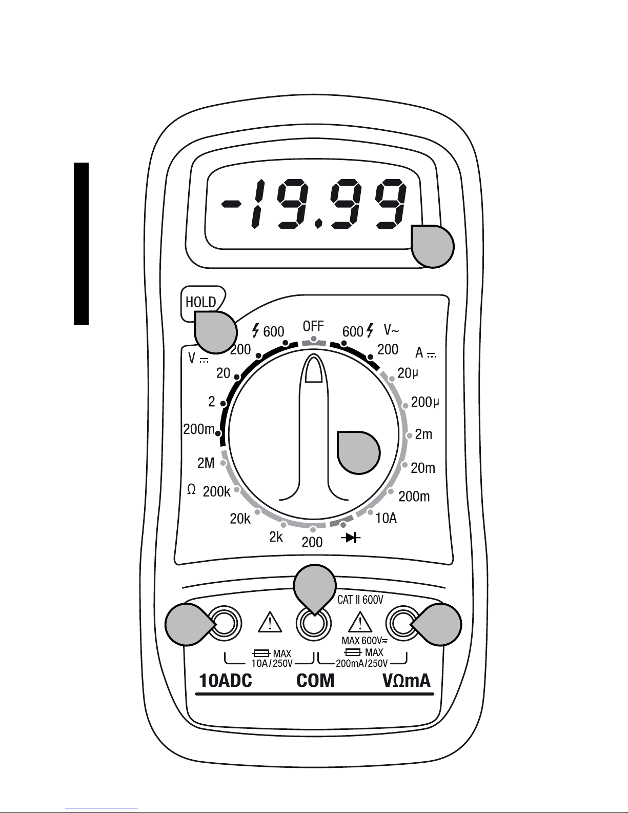
fRONT pANEL DESCRIpTION
2
6
5
4
1
3

1. DISpLAy 3 ½ digit, 7 segment, 15mm high LCD.
2. fUNCTION AND RANGE SwITCh This switch is used to
select the function and desired range as well as to turn on the
instrument. To extend the life of its battery, the switch should be
in the OFF position when the instrument is not in use.
3. ‘hOLD’-bUTTON by pressing this button the screen will retain
the last reading and the symbol H appear in the LCD until you
next press the button.
4. 10A jACk Plug in connector for red (positive) test lead for 10A
measurements.
5. COMMON jACk Plug in connector for black (negative) test lead.
6. VΩMA jACk Plug in connector for red (positive) test lead for all
voltage and resistance and current (except 10A) measurements.
SpECIfICATIONS
Accuracies are guaranteed for 1 year, 23˚C ± 5˚C, less than 80% RH.
DC VOLTAGE
Range Resolution Accuracy
200µV 100µV ±0.5% of rdg ±3D
2V 1mV ±0.5% of rdg ±3D
20V 10mV ±0.5% of rdg ±3D
200V 100mV ±0.5% of rdg ±3D
600V 1V ±0.8% of rdg ±5D
Overload protection: 250 V rms for level of 200 µV, and 600V DC
or rms AC for other levels.

DC CURRENT
Range Resolution Accuracy
20µV 0.01µA ±1% of rdg ±3D
200µV 0.1µA ±1% of rdg ±3D
2mA 1µA ±1% of rdg ±3D
20mA 10µA ±1% of rdg ±5D
200mA 100µA ±1.5% of rdg ±5D
10A 10mA ±2% of rdg ±10D
Overload protection: mA jack F250mA/250V Fuse
AC VOLTAGE
Range Resolution Accuracy
200V 100mV ±1.2% of rdg ±10D
600V 1V ±1.2% of rdg ±10D
Overload protection: 600V DC or rms AC for all levels.
Frequency range: 40Hz – 400Hz.
RESISTANCE
Range Resolution Accuracy
200 ohm 0.1 ohm ±0.8% of rdg ±5D
2k ohm 1 ohm ±0.8% of rdg ±2D

20k ohm 10 ohm ±0.8% of rdg ±2D
200k ohm 100 ohm ±0.8% of rdg ±2D
mk ohm 1k ohm ±1.0% of rdg ±5D
Maximum open circuit voltage: 3.2V
Overload protection: 250V DC or rms for all levels.
OpERATING INSTRUCTIONS
wARNING: To avoid electrical shock hazard and/or damage
of the instrument, do not measure voltages that might exceed
DC 600V or AC 600V above earth ground. Before using
instrument, inspect test leads, connectors and probes for
cracks, breaks or crazes in the insulation.
DC VOLTAGE MEASUREMENT
1. Connect red test leads to “V Ω mA” jack, black leads to “COM”
jack.
2. Set switch to desired DCV position. If the voltage to be
measured is not known beforehand, set switch to the highest
range and reduce it until satisfactory reading is obtained.
3. Connect leads to device or circuit being measured.
4. Voltage value will appear on the display along with the
voltage polarity.
AC VOLTAGE MEASUREMENT
1. Connect red test leads to “V Ω mA” jack, black leads to “COM”
jack.
2. Set switch to desired ACV position.

3. Connect test leads to device or circuit being measured.
4. Voltage value will appear on the display along with the
voltage polarity.
DC CURRENT MEASUREMENT
1. Connect red lead to “V Ω mA” jack, black leads to “COM” jack.
2. Set switch to desired DCA position.
3. Open the circuit to be measured, and connect test leads IN
SERIES with the load in which current is to be measured.
4. Read current value on the display.
RESISTANCE MEASUREMENT
1. Connect red lead to “V Ω mA” jack, black leads to “COM” jack.
2. Set switch to desired Ω position.
3. If the resistance being measured is connected to a circuit, turn
off power and discharge all capacitors before measurement.
4. Connect test leads to circuit being measured.
5. Read resistance value on the display.
DIODE MEASUREMENT
1. Connect red lead to “V Ω mA” jack, black leads to “COM” jack.
2. Set switch to position.
3. Connect the red test lead to the anode of the diode to be
measured and black test lead to cathode.
4. The forward voltage drop in mV will be displayed. If the diode
is reserved, figure “1” will be shown.
TRANSISTOR hfE MEASUREMENT
1. Set switch to the hFE position.
2. Determine whether the transistor is NPN of PNP type and
locate the emitter, base and collecter leads. Insert the leads
into the proper holes of the hFE socket on the front panel.
3. The meter will display the approximate hFE value at the
condition of base current 10µA and VCE 3V.

bATTERy AND fUSE REpLACEMENT
Fuse rarely needs replacement and will blow almost always as
a result of an operating error. If appears on the display,
it indicates that the battery should be replaced. To replace the
battery and fuse (200mA/250V) remove the two screws at the
bottom of the case. Simply remove the old and replace with a
new one. Be careful to observe polarity.
CAUTION Before attempting to open the case of the instrument,
be sure to disconnect test leads from any energized circuits to
avoid shock hazard.
DECLARATION Of CONfORMITy
Service Best International B.V.
De Run 4271
5503 LM Veldhoven - the Netherlands
hereby declares that this Carpoint Multimeter Digital is in
compliance with the essential requirements and other relevant
provisions of Directives 2006/95/EC, 2004/108/EC,
EN 61326-1, EN 61326-2-1.
A copy of the declaration of conformity can be found at:
http://www.carpointeurope.com/support

GEbRUIkSAANwIjZING
ALGEMEEN
Dit instrument is een compacte (3½ digit) multimeter voor het
meten van DC en AC spanningen, DC stromen, weerstand en
diodemetingen. Er is een volle bereik overbelastingsbescherming
en een indicatie als de batterijspanning te laag wordt. Het
is een ideaal instrument voor gebruik in het veld, zoals het
laboratorium, de werkplaats, hobby en thuisgebruik.
VEILIGhEIDSINfORMATIE
Volg de handleiding en de veiligheidsinstructies nauwkeurig
om de juiste werking van het apparaat te garanderen. Totale
overeenstemming met de veiligheidsstandaarden, kan alleen
gegarandeerd worden als met de bijgeleverde testkabels wordt
gewerkt. Als het nodig is, kunnen deze worden vervangen door
hetzelfde type zoals aangeduid is in deze handleiding.
ONDERhOUD
- Voordat u de multimeter opent, dienen alle testkabels van een
elektrische aansluiting losgekoppeld te zijn.
- Om bescherming tegen brand te behouden, dient de zekering
alleen vervangen te worden met een zekering van dezelfde
voltage en onder normale werkomstandigheden F250mA /
250V.
- Gebruik de multimeter niet als de beschermkap niet aanwezig
is of niet goed sluit.
- Gebruik geen schoonmaakmiddelen en vloeistoffen op de
multimeter. Gebruik om schoon te maken een vochtige doek

en een licht reinigingsmiddel.
ALGEMEEN GEbRUIk
- Overschrijd nooit de maximale beschermingswaarden,
vermeld in de specificaties van elk type meting.
- Wanneer de multimeter bezig is met een meting, raak dan de
terminals die niet in gebruik zijn, niet aan.
- Gebruik de multimeter niet om spanningen te meten van meer
dan 600V boven de aardedraad in categorie II installaties.
- Wanneer het niveau van de waarden die moeten worden
gemeten onbekend is voorafgaand aan de meting, plaats dan
de niveau selector op de hoogste stand.
- Voordat de selector wordt gedraaid om van functie te
veranderen, dienen alle testkabels losgekoppeld te worden.
- Houdt u er bij het uitvoeren van metingen op de televisie of
elektronische schakelaars, altijd rekening mee dat er sprake
zou kunnen zijn van hoogspanning in de controlepunten
waardoor de multimeter defect kan raken.
- Wanneer u werkt met stroom boven de 60V DC of 30 V AC
of rms, zorg er dan voor dat uw vingers tijdens het meten
beschermd worden.
- Voordat u probeert transistor door te meten, moeten alle
testkabels losgekoppeld zijn van elke schakelaar.
- Onderdelen mogen niet worden gekoppeld aan een hFE-plug
wanneer er stroom door de testkabels wordt gestuurd.
- Verricht nooit weerstandsmetingen op operationele
schakelaars.
bESChRIjVING fRONTpANEEL
2
6
5
4
1
3

1. DISpLAy 3 ½ digit, 7 segment, 15mm hoog LCD.
2. fUNCTIE- EN bEREIkSChAkELAAR Deze schakelaar
wordt gebruikt om de functie en het bereik te selecteren, en
om het instrument in te schakelen. Om de levensduur van de
batterij te verlengen, moet de schakelaar in de stand OFF
staan als het instrument niet wordt gebruikt.
3. hOLD kNOp Door op deze knop te drukken, zal de laatste
meting worden onthouden, het symbool ‘H’ zal in het scherm
verschijnen totdat er weer op de ‘hold- knop gedrukt wordt.
4. 10A AANSLUITING Plug hier de rode (positieve)
meetdraad in voor 10A metingen.
5. COMMON AANSLUITING Plug hier de zwarte (negatieve)
meetdraad in.
6. VΩMA AANSLUITING Plug hier de (rode) positieve
meetdraad in voor alle spannings-, weerstand- en
stroommetingen (uitgezonderd 10A).
SpECIfICATIES
De nauwkeurigheid wordt gegarandeerd gedurende 1 jaar, 23˚C
± 5˚C, minder dan 80% RV.
DC SpANNING
Bereik Resolutie Nauwkeurigheid
200µV 100µV ±0,5% aflezing ±3D
2V 1mV ±0,5% aflezing ±3D
20V 10mV ±0,5% aflezing ±2D
200V 100mV ±0,5% aflezing ±2D
600V 1V ±0,8% aflezing ±5D
Overbelastingbeveiliging: 250V rms op het bereik 200mV en 600V DC of
rms AC voor de andere bereiken.

DC CURRENT
Bereik Resolutie Nauwkeurigheid
20µV 0.01µA ±1% aflezing ±3D
200µV 0.1µA ±1% aflezing ±3D
2mA 1µA ±1% aflezing ±3D
20mA 10µA ±1% aflezing ±5D
200mA 100µA ±1.5% aflezing ±5D
10A 10mA ±2% aflezing ±10D
Overbelastingbeveiliging: mA jack F250mA/250V zekering.
AC SpANNING
Bereik Resolutie Nauwkeurigheid
200V 100mV ±1,2% aflezing ±10D
600V 1V ±1,2% aflezing ±10D
Overbelastingbeveiliging: 600V DC of rms AC voor alle bereiken.
Frequentiebereik: 40Hz – 400Hz.
wEERSTAND
Bereik Resolutie Nauwkeurigheid
200 ohm 0.1 ohm ±0,8% aflezing ±5D
2k ohm 1 ohm ±0,8% aflezing ±2D
20k ohm 10 ohm ±0,8% aflezing ±2D
200k ohm 100 ohm ±0,8% aflezing ±2D
2mk ohm 1k ohm ±1,0% aflezing ±5D
 Loading...