

CarpeStar SMG Series, SMG4008, SMG4004, SMG4016, SMG4032 User Manual

Wireless Gateway
Version 1.9.0
CarpeStar SMG Series W ir eless Gatew ay
SMG4004
SMG4008
SMG4016
SMG4032
www.carpestar.com

Content
Content ................................................................................................... i
Copyright Declaration ......................................................................... iv
Revision History ................................................................................... v
Chapter 1 Product Introduction ........................................................... 1
1.1 Typical Application ......................................................................................... 3
1.2 Feature List .................................................................................................... 3
1.3 Hardware Description .................................................................................... 4
1.4 Indicator Info .................................................................................................. 7
Chapter 2 Quick Guide ......................................................................... 9
Chapter 3 WEB Configuration ........................................................... 12
3.1 System Login ............................................................................................... 12
3.2 Operation Info .............................................................................................. 13
3.2.1 System Info .............................................................................................................. 13
3.2.2 Port State .................................................................................................................. 14
3.2.3 Call Count ................................................................................................................. 15
3.2.4 SIP Message Count ................................................................................................. 18
3.3 Quick Config ................................................................................................ 19
3.4 VoIP Settings ............................................................................................... 21
3.4.1 SIP ............................................................................................................................ 22
3.4.2 SIP Compatibility ...................................................................................................... 24
3.4.3 SIP Station ................................................................................................................ 26
3.4.4 SIP Server ................................................................................................................ 28
3.4.5 NAT Setting .............................................................................................................. 30
3.4.6 Media ........................................................................................................................ 32
3.5 Advanced Settings ....................................................................................... 34
3.5.1 Network .................................................................................................................... 35
3.5.2 System Param .......................................................................................................... 36
3.5.3 Service Config .......................................................................................................... 38
3.5.4 Dialing Rule .............................................................................................................. 40
3.5.5 Function Key ............................................................................................................ 43
3.5.6 Cue Tone .................................................................................................................. 44
3.5.7 Color Ring ................................................................................................................ 44
3.5.8 QoS .......................................................................................................................... 46
3.5.9 Tone Generator ........................................................................................................ 47
3.5.10 CDR Query ............................................................................................................... 48
3.5.11 VPN .......................................................................................................................... 48
3.6 Wireless Settings ......................................................................................... 49
3.6.1 Basic Parameters ..................................................................................................... 51
3.6.2 Wireless Param ........................................................................................................ 56
3.6.3 Call Forwarding ........................................................................................................ 58
3.6.4 Short Message ......................................................................................................... 59
3.6.5 IMEI .......................................................................................................................... 62
CMG Series Wireless Gateway User Manual (Version 1.9.0)
Page i

3.6.6 USSD........................................................................................................................ 63
3.6.7 Email......................................................................................................................... 64
3.6.8 SIM Card .................................................................................................................. 66
3.6.9 PIN Manage ............................................................................................................. 67
3.6.10 BS Select .................................................................................................................. 69
3.6.11 Networking Settings ................................................................................................. 71
3.6.12 AMD .......................................................................................................................... 73
3.6.13 Hidden CallerID ........................................................................................................ 74
3.6.14 SIM Mode ................................................................................................................. 75
3.6.15 Call Waiting .............................................................................................................. 75
3.7 Call Management ......................................................................................... 75
3.7.1 Balance .................................................................................................................... 76
3.7.2 Port Timer ................................................................................................................. 78
3.7.3 Name List Timer ....................................................................................................... 80
3.7.4 Tel to IP Auto Route ................................................................................................. 82
3.7.5 Blacklist .................................................................................................................... 83
3.7.6 SMS Count ............................................................................................................... 84
3.7.7 Auto Function ........................................................................................................... 85
3.7.8 Port Charge .............................................................................................................. 86
3.8 Port Settings ................................................................................................ 88
3.8.1 Port ........................................................................................................................... 88
3.8.2 Port Group ................................................................................................................ 92
3.9 Route Settings ............................................................................................. 95
3.9.1 Routing Parameters ................................................................................................. 95
3.9.2 IP to Tel/IP ................................................................................................................ 96
3.9.3 Tel to IP .................................................................................................................... 98
3.10 Number Manipulation ................................................................................. 100
3.10.1 IP to Tel/IP CallerID ................................................................................................ 101
3.10.2 IP to Tel/IP CalleeID ............................................................................................... 105
3.10.3 Tel to IP CallerID .................................................................................................... 106
3.10.4 Tel to IP CalleeID .................................................................................................... 110
3.11 System Tools .............................................................................................. 111
3.11.1 Upgrade .................................................................................................................. 112
3.11.2 Signaling Capture ................................................................................................... 114
3.11.3 Data Recording ...................................................................................................... 115
3.11.4 Call Log .................................................................................................................. 115
3.11.5 Operation Log......................................................................................................... 116
3.11.6 Change Password .................................................................................................. 117
3.11.7 Backup & Upload ................................................................................................... 117
3.11.8 Factory Reset ......................................................................................................... 118
3.11.9 Restart .................................................................................................................... 119
3.11.10 System Monitor ...................................................................................................... 119
3.11.11 Centralized Manage ............................................................................................... 120
3.11.12 PING Test ............................................................................................................... 121
3.11.13 TRACERT Test ....................................................................................................... 122
3.11.14 Wireless Network Test ............................................................................................ 123
3.11.15 Module Test ............................................................................................................ 124
3.11.16 Access Control ....................................................................................................... 124
3.11.17 Device Lock ............................................................................................................ 126
Appendix A Technical Specifications .............................................. 127
Appendix B Troubleshooting ........................................................... 128
Appendix C About VPN .................................................................... 129
SMG Series Wireless Gateway User Manual (Version 1.9.0)
Page ii

Appendix D Technical/sales Support .............................................. 133
SMG Series Wireless Gateway User Manual (Version 1.9.0)
Page iii

Copyright Declaration
All rights reserved; no part of this document may be reproduced or transmitted in any form or by
any means, electronic or mechanical, without prior written permission from CarpeStar
Information Engineering Co., Ltd (hereinafter referred to as „CarpeStar‟).
CarpeStar reserves all rights to modify this document without prior notice. Please contact
CarpeStar for the latest version of this document before placing an order.
CarpeStar has made every effort to ensure the accuracy of this document but does not
guarantee the absence of errors. Moreover, CarpeStar assumes no responsibility in obtaining
permission and authorization of any third party patent, copyright or product involved in relation
to the use of this document.
SMG Series Wireless Gateway User Manual (Version 1.9.0)
Page iv
Revision History
Version
Date
Comments
Version 1.0.0
2015-08
Initial publication
Version 1.1.0
2015-11
New Revision
Version 1.2.0
2016-1
New Revision
Version 1.3.0
2016-4
New Revision
Version 1.4.0
2016-6
New Revision
Version 1.5.0
2016-12
New Revision
Version 1.6.0
2017-03
New Revision
Version 1.7.0
2017-05
New Revision
Version 1.8.0
2017-10
New Revision
Version 1.9.0
2018-03
New Revision
Note: Please visit our website to obtain the latest version of this document.
www.carpestar .com
SMG Series Wireless Gateway User Manual (Version 1.9.0)
Page v
Chapter 1 Product Introduction
Series
Module & Ports
Supported Frequency Band/Code
GSM Gateway
GSM: 850/900/1800/1900MHz
WCDMA Gateway
GSM: 900/1800MHz
UMTS: 900/2100MHz
WCDMA-A Gateway
GSM: 850/900/1800/1900MHz
UMTS: 850/1900MHz
WCDMA-T Gateway
GSM: 850/900/1800/1900MHz
UMTS: 850/2100MHz
WCDMA-Z Gateway
GSM: 850/900/1800/1900MHz
UMTS: 850/900/1900/2100MHz
Thank you for choosing Carpe Star SM G Series Wirele ss
The CarpeStar CMG series wireless gateway products (hereinafter referred to as ‘wir
gat eway
ing
the wire less
and
the
the
SIM
See below table for the modules of CMG series wireless gateway:
’),
wireless module,
card,
as
quite
a
network
part
adv anced
of
th e
with
uses
t he
in
SMG4032-32G
SMG4016-16G
SMG4008-8G
SMG4004-4G
SMG4016-16W
Carp
the
techno logy.
eStar
V oIP
push-pull
gatew
network.
SIM
So
Gatew ay!
ay
It
card
far,
produ ct s,
adopts
socket
only
CM G4008
an
w orks
updated
for
ea sy
is available.
mai
nly
for
VoIP
processor
repla ceme nt
c
eless
onnect
of
SMG4008-8W
SMG4004-4W
SMG4032-32WA
SMG4016-16WA
SMG4008-8WA
SMG4004-4WA
SMG4016-16WT
SMG4008-8WT
SMG4004-4WT
SMG4016-16WZ
SMG Series Wireless Gateway User Manual (Version 1.9.0)
SMG4008-8WZ
Page 1

CDMA Gateway
CDMA: CDMA 2000 800MHz
LTE Gateway
FDD LTE: B1/B3/B5/B7/B8/B20
TDD LTE: B38/B40/B41
WCDMA: B1/B5/B8
GSM: B3/B8
FDD LTE: B1/B3
TDD LTE: B38/B39/B40/B41
TDSCDMA: B34/B39
WCDMA: B1
CDMA2000 1X/EVDO: BC0
GSM: 900/1800MHz
SMG4004-4WZ
SMG4032-32C
SMG4016-16C
SMG4008-8C
SMG4004-4C
SMG4032-32LE
SMG4016-16LE
SMG4008-8LE
SMG4004-4LE
SMG4032-32LC
SMG4016-16LC
SMG4008-8LC
SMG4004-4LC
Table 1-1 Model List
SMG Series Wireless Gateway User Manual (Version 1.9.0)
Page 2
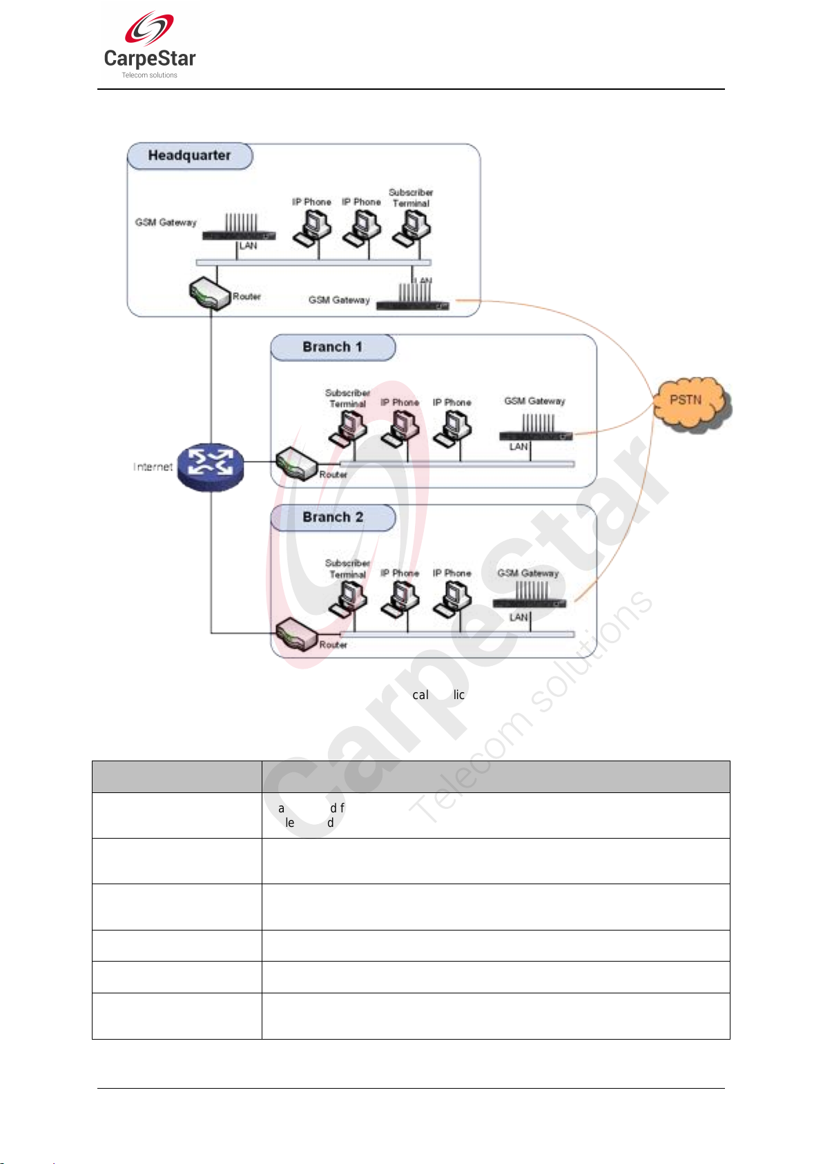
1.1 Typical Application
Basic Features
Description
TDM Call
Call initiated from TDM to IP, via routing and number manipulation to obtain the
called IP address.
IP Call
Call initiated from IP to TDM, via routing and number manipulation to obtain the call
destination.
Number Manipulation
Peels off some digits of a phone number from left/right, or adds a prefix/suffix to a
phone number.
Call Forward
Three options available: Unconditional, Busy, No Reply and Unreachable.
CID
Displays the CallerID.
Echo Cancellation
Provides the echo cancellation feature for a call conversation over the wireless
port.
1.2 Feature List
Figure 1-1 Typical Application
SMG Series Wireless Gateway User Manual (Version 1.9.0)
Page 3
TDM/VoIP Routing
Sets a routing path: from IP to TDM or from TDM to IP.
Simultaneous Register to
Multiple Servers
Registers the gateway to a master registrar server and a spare registrar server
simultaneously.
IMS Network
Registers the gateway to a server under IMS network.
Custom IVR Recording
Provides the interface to customize the IVR Recording.
White/Black List
Allows the setting of the white/black list for WEB access.
Voice Gain Adjust
Supports the gain adjustment for the received or sent voice.
Receive or Send
SMS/USSD
Supports the SMS sending and receiving, as well as the USSD request and
response.
Auto Select Network
Supports the auto identification and selection of the network operator.
SMS CODEC
Two options available: ASCII and UCS2.
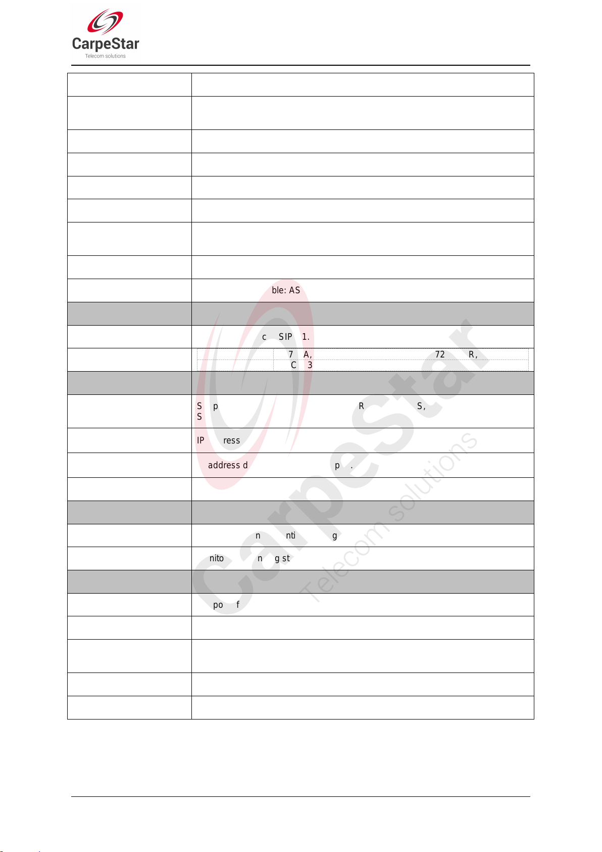
Signaling & Protocol
Description
SIP Signaling
Supported protocol: SIP V1.0/2.0, RFC3261.
Voice
CODEC
G.711A, G.711U, G.729A/B, G.723, G.722, AMR, iLBC
DTMF Mode
RFC2833, SIP INFO, INBAND
Network
Description
Network Protocol
Supported protocol: TCP/UDP, HTTP, ARP/RARP, DNS, NTP, TFTP, TELNET,
STUN.
Static IP
IP address modification support.
DHCP
IP address dynamic allocation support.
DNS
Domain Name Service support.
Security
Description
Admin Authentication
Supports admin authentication to guarantee the resource and data security.
System Monitor
Monitors the running status of the system and the server.
Maintain & Upgrade
Description
WEB Configuration
Support of configurations through the WEB user interface.
Language
Chinese, English.
Software Upgrade
Support of user interface, gateway service, kernel and firmware upgrades based
on WEB.
Tracking Test
Support of Ping and Tracert tests based on WEB.
SysLog Type
Three options available: ERROR, WARNING, INFO.
1.3 Hardware Description
The wireless gateway supports two LANs and adopts an external 12V power supply. See below
SMG Series Wireless Gateway User Manual (Version 1.9.0)
Page 4
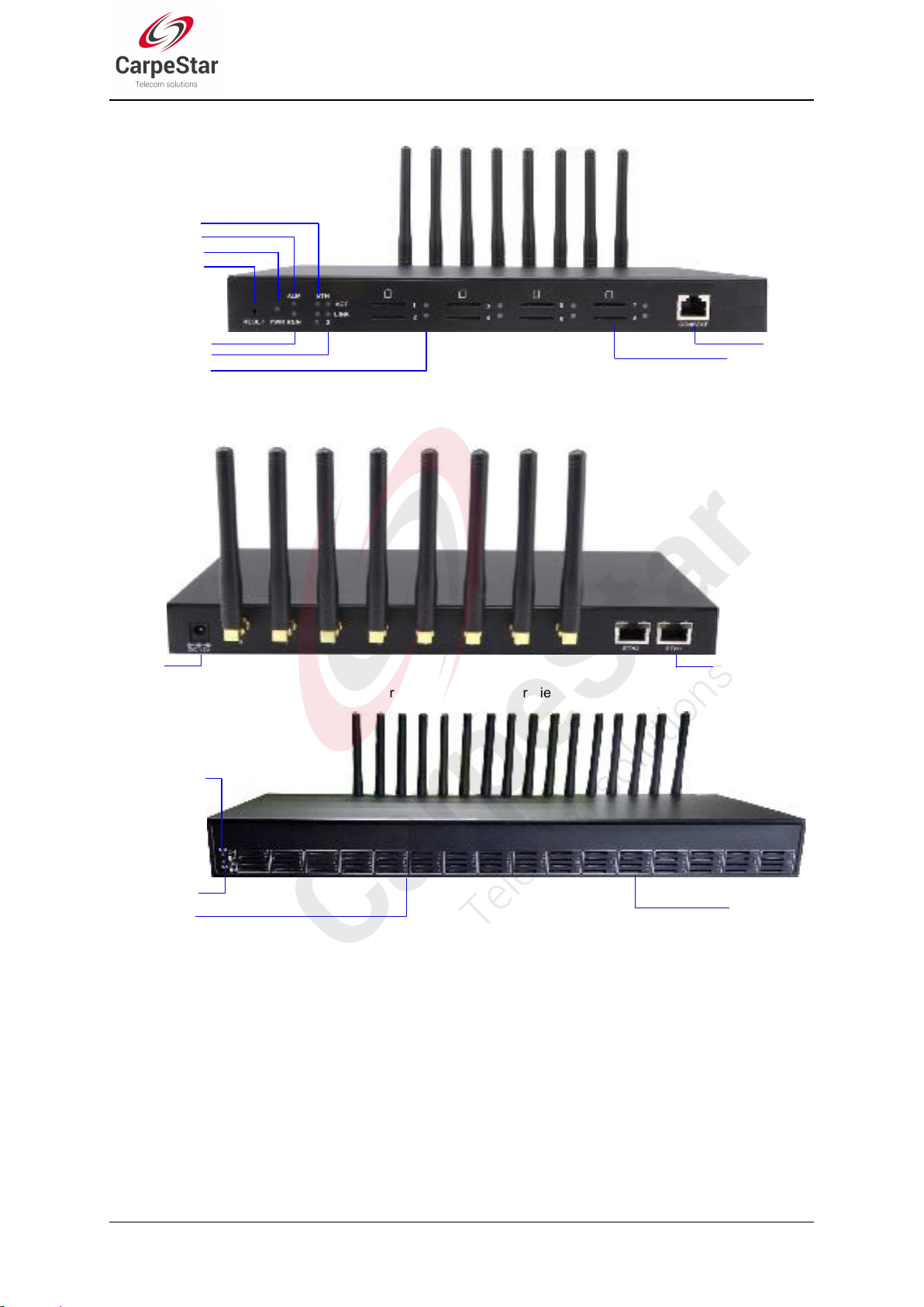
for product appearance.
Alarm Indicator
SIM Card Slot
Indicator
Run Indicator
SIM Card Slot
Network Port
Power
Alarm Indicator
Power Indicator
Channel Indicator
Console
LAN2 Indicator
LAN1 Indicator
SIM Card Slot
Reset Button
Run Indicator
Figure 1-2 SMG4008 Front View
Figure 1-3 CMG4008 Rear View
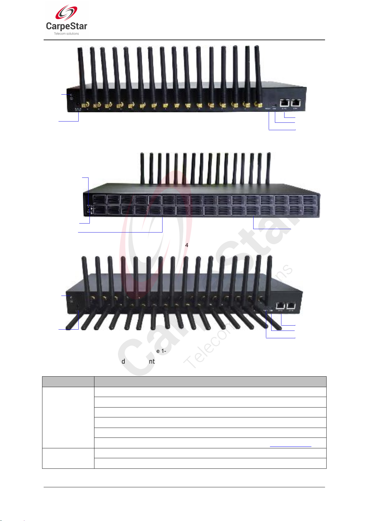
Figure 1-4 SMG4016 Front View
SMG Series Wireless Gateway User Manual (Version 1.9.0)
Page 5
Interface
Description
LAN
Amount: 2
Type: RJ-45
Bandwidth: 10/100 Mbps
Self-Adaptive Bandwidth Supported
Auto MDI/MDIX Supported
Built-in Link indicator and ACTIVE indicator. For more details, refer to 1.4 Indicator Info
SIM Card Slot
Amount: 4, 8, 16*4, 32*4
Network Supported: GSM, WCDMA, CDMA, VoLTE
Network Port
Power
Console
Reset Button
Grouding
Stud
Alarm Indicator
SIM Card Slot
Indicator
Run Indicator
SIM Card Slot
Network Port
Power
Console
Reset Button
Grouding
Stud
Figure 1-5 CMG4016 Rear View
Figure 1-6 SMG4032 Front View
Figure 1-7 SMG4032 Rear View
The table below gives a detailed introduction to the interfaces, buttons and LEDs illustrated
above:
SMG Series Wireless Gateway User Manual (Version 1.9.0)
Page 6

Console Port
Amount: 1
Type: RS-232
Baud Rate: 115200bps
Connector: RJ45 to DB-9 Connector (4004, 4008 series), Mini-USB connecting line (4016,
4032 series)
Data Bits: 8 bits
Stop Bit: 1 bit
Parity Unsupported
Flow Control Unsupported
External Power
Supply Interface
Provide the 12V voltage with positive inside and negative outside, and the current is larger
than 3A
Button
Description
Reset Button
Restore the gateway to factory settings by pressing this button persistently for 3 seconds
LED
Description
Power Indicator
Indicates the power state. It lights up when the gateway starts up with the power cord well
connected
Run Indicator
Indicates the running status. For more details, refer to 1.4 Indicator Info.
Alarm Indicator
Alarms the device malfunction. For more details, refer to 1.4 Indicator Info.
Link Indicator
The green LED on the right of LAN, indicating the network connection status.
ACT Indicator
The orange LED on the left of LAN, whose flashing tells the data are being transmitted.
Port Indicator
1. When the port is idle, the LED Lights up in green and keeps on;
2. When the port is unavailable, the LED Lights up in red and keeps on;
3. When the port is in use, the LED flashes in green
4. When the port module is disabled, the LED flashes in red
LED
State
Description
Run Indicator
Go out
System is not yet started.
Light up and flash fast
System is starting.
Flash slowly
Device is normal.
Alarm Indicator
Go out
Device is normal.
Light up
Upon startup: Device is normal.
In runtime: Device is abnormal.
Flash
Device is abnormal.
5. For CMG4016 series, only the indicator of the card slot in which the SIM card is in
using lights up and other indicators will go out in the case that there are more than one
SIM cards inserted in the same channel.
For other hardware parameters, refer to Appendix A Technical Specifications.
1.4 Indicator Info
The wireless gateway is equipped with two indicators denoting the system‟s running status: Run
Indicator (green LED) and Alarm Indicator (red LED). The table below explains the states and
meanings of the two indicators.
Note:
SMG Series Wireless Gateway User Manual (Version 1.9.0)
Page 7

The startup process consists of two stages: System Booting and Gateway Service
Startup. The system booting costs about 1 minute and once it succeeds, both the run
indicator and the alarm indicator light up. Then after the gateway service is successfully
started and the device begins to work normally, the run indicator flashes and the alarm
indicator goes out.
During runtime, if the alarm indicator lights up or flashes, it indicates that the device goes
abnormal. If you cannot figure out and solve the problem by yourself, please contact our
technicians for help. Go to Appendix D Technical/sales Support to find the contact way.
SMG Series Wireless Gateway User Manual (Version 1.9.0)
Page 8
Chapter 2 Quick Guide
External Power Supply
offers 12V voltage
This chapter is intended to help you grasp the basic operations of the wireless gateway in the
shortest time.
Step 1: Confirm that your packing box contains all the following things.
Wireless Gateway *1
External 12V Power Adapter *1
GSM/WCDMA/CDMA/LTE Rubber Antenna *4/8/16/32
Standard RJ45 to DB-9 Switcher (4004/4008 series) *1, Mini-USB connecting line
(4016/4032 series) *1
8mm Antenna Wrench *1
Rubber Foot Pad *4
Network Cable *1
Warranty Card *1
Installation Manual *1
Step 2: Connect the network cable.
This product provides RJ-45 interfaces.
Step 3: Insert the SIM card (standard size) and install the antenna.
The wireless gateway provides a SIM card slot. You are required to insert the SIM card before
using it. Take out the rubber antennae from the packing box, install them onto the wireless
gateway, screw them up and evenly arrange them.
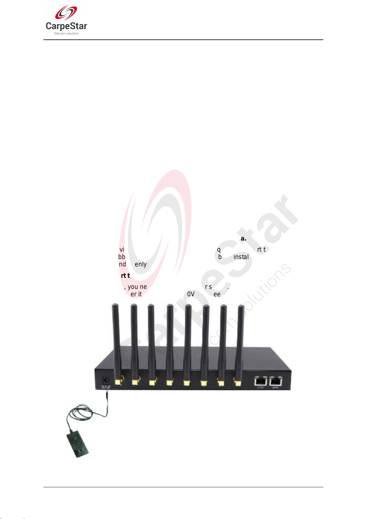
Step 4: Power on and start the gateway.
To use the wireless gateway, you need an external power supply. Insert it to the power interface of
the wireless gateway and power it on with 100~240V AC. See the figure below:
Figure 2-1 Wireless Gateway Power Connection
SMG Series Wireless Gateway User Manual (Version 1.9.0)
Page 9
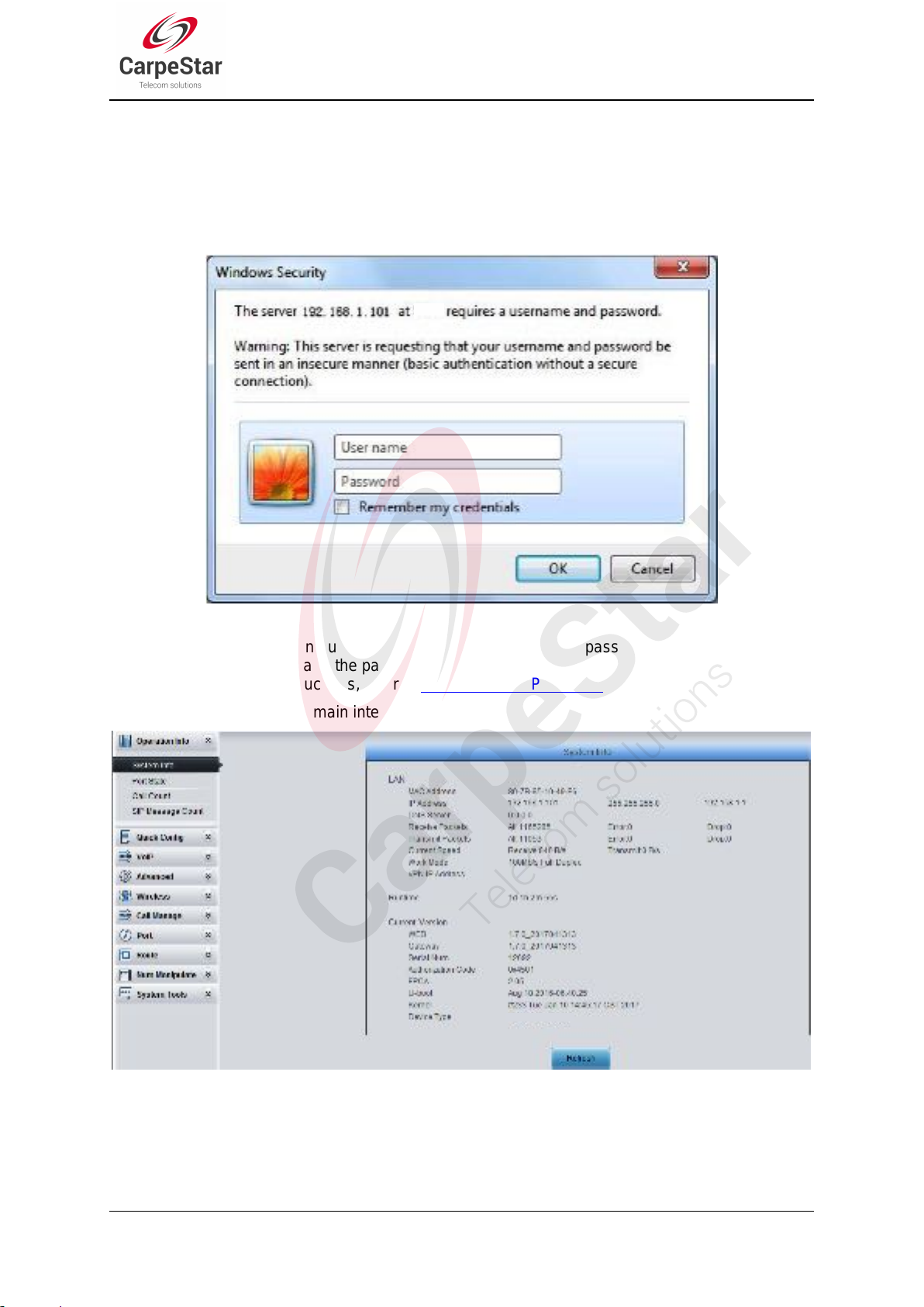
Step 5: Log in the gateway.
Enter the original IP address (192.168.1.101) of the wireless gateway in the browser to go to the
WEB interface of the gateway. The original username and password of the gateway are both
„admin‟. For detailed instructions about login, refer to 3.1 System Login. We suggest you change
the initial username and password via „System Tools Change Password‟ on the WEB interface
as soon as possible after your first login. For detailed instructions about changing the password,
refer to 3.11.6 Change Password. After changing the password, you are required to log in again.
Step 6: Modify IP address of the gateway.
You can modify the IP address of the gateway via „Advanced Settings Network‟ on the WEB
interface to put it within your company‟s LAN. Refer to 3.5.1 Network for detailed instructions
about IP modification. After changing the IP address, you shall log in the gateway again using
your new IP address.
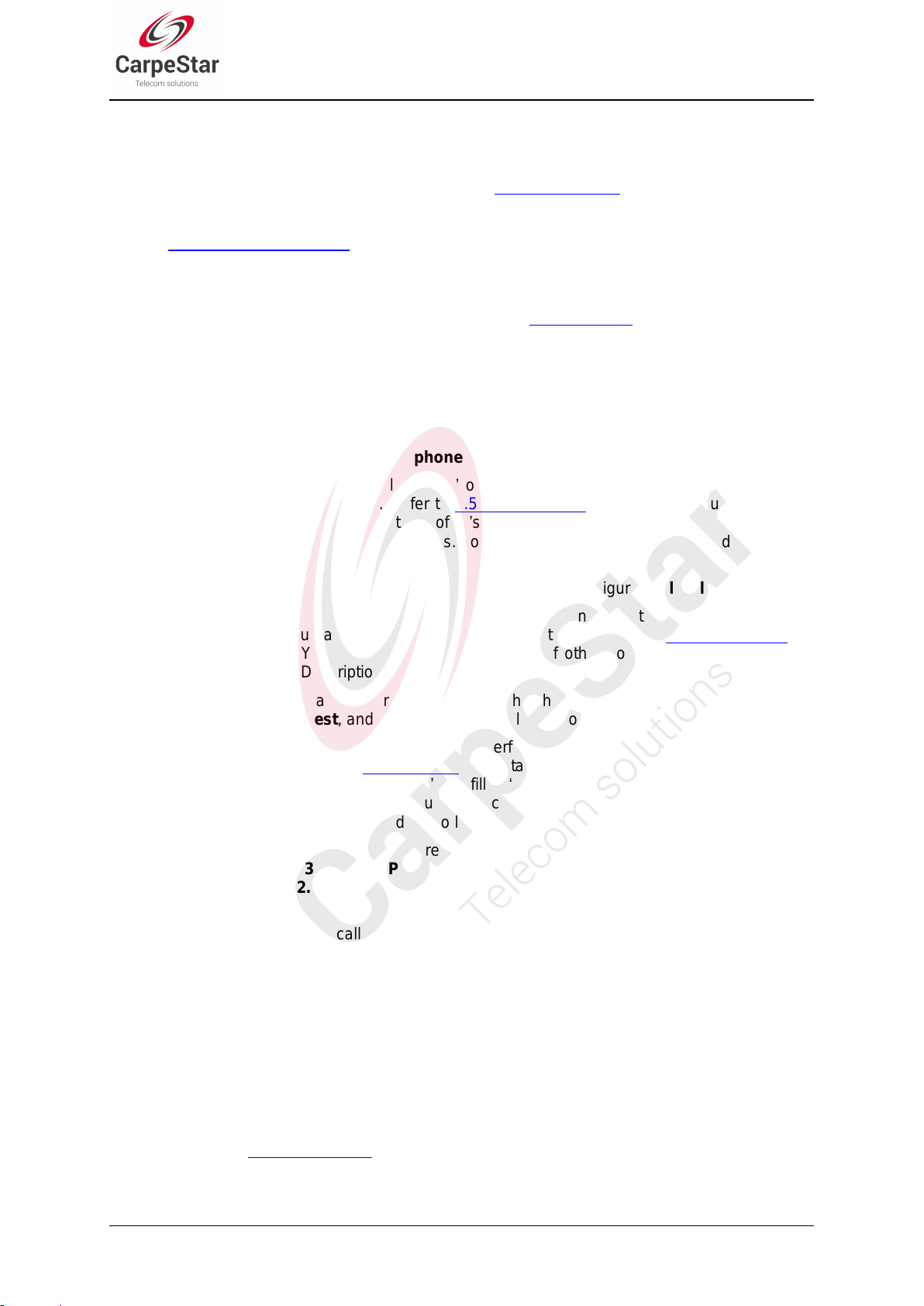
Step 7: Make phone calls.
Note: For your easy understanding and manipulation, all examples given in this step do not
involve registration, that is, SIP initiates calls in a point-to-point mode.
Situation 1: Call from a station to an IP phone (TelIP)
1. Go to „Advanced Settings Dialing Rule‟ on the WEB interface and click the „Add New‟
button to add a new dialing rule. Refer to 3.5.4 Dialing Rule for detailed instructions. Enter
either a particular number or a string of „x‟s to represent several random numbers. For
example, „xxx‟ denotes 3 random numbers. You may use the default value of „Index‟ and are
required not to leave „Description‟ empty.
Example: Set Index to 99, fill in Description with test and configure Dial Rule to 123.
2. Go to „Port Settings Port Group‟ on the WEB interface and click the „Add New‟ button to
create a new port group and add the corresponding ports to it. Refer to 3.8.2 Port Group for
detailed instructions. You may use the default values of other configuration items and are
required not to leave „Description‟ empty.
Example: Provided the added port is Port1, check the checkbox before Port1, set Index to 1,
fill in Description with test, and keep the default values of other configuration items.
3. Go to „Route Settings TelIP‟ on the WEB interface and click the „Add New‟ button to add
a new routing rule. Refer to 3.9.3 TelIP for detailed instructions. Select the port group
created in Step2 as „Source Port Group‟ and fill in „Destination IP‟ and „Destination Port‟ with
the IP address and the Port number you plan to call. You may use the default values of other
configuration items and are required not to leave „Description‟ empty.
Example: Provided the remote IP address intended to call is 192.168.0.111 and the port is
5060. Set Index to 63, Source Port Group to 1, fill in Description with test, configure
Destination IP to 192.168.0.111, Destination Port to 5060, and keep the default values of
other configuration items.
4. Use an external phone to call the number of this SIM card, and then follow the cue tone to
dial the number set in Step1 to ring the remote IP phone If you have set a particular number in
Step 1, only this number you can dial; if you have set a string of „x‟s, how many „x‟s there are,
how many random numbers you can dial.
Example: The external phone dials the number of this SIM card, and then follows the cue
tone to dial 123. Then the IP phone with the IP address 192.168.0.111 and the port 5060 will
ring.
Situation 2: Call from an IP phone to a station (IP Tel)
1. Go to „Port Settings Port Group‟ on the WEB interface and click the „Add New‟ button to
create a new port group and add the corresponding ports which are connected with stations
to it. Refer to 3.8.2 Port Group for detailed instructions. You may use the default values of
other configuration items and are required not to leave „Description‟ empty.
CMG Series Wireless Gateway User Manual (Version 1.9.0)
Page 10

Example: Provided the added port is Port1, check the checkbox before Port1, set Index to 1,
fill in Description with test, and keep the default values of other configuration items.
2. Go to „Route Settings IPTel/IP‟ on the WEB interface and click the „Add New‟ button to
add a new routing rule. Refer to 3.9.2 IPTel/IP for detailed instructions. Fill in „Source IP‟
with the IP address which initiates the call and select the port group created in Step1 as
„Destination Port Group‟. You may use the default values of other configuration items and
required not to leave „Description‟ empty.
Example: Provided the IP address of the IP phone which initiates the call is 192.168.0.111.
Set Index to 63, Destination Port Group to 1, fill in Description with test, configure Source
IP to 192.168.0.111, and keep the default values of other configuration items.
3. Pick up the IP phone and call the IP address and port of the wireless gateway to make
outgoing calls from the wireless channel.
Example: Provided the IP address of the wireless gateway is 192.168.0.101, the port is 5060,
use the IP phone to call the IP address 13529101232@192.168.0.101 and then the first idle
wireless port in the port group of step 2 will make an outgoing call to 13529101232.
Special Instructions:
As the device will gradually heat up while being used, please maintain good ventilation to
prevent sudden failure, ensuring that the ventilation holes are never jammed.
During runtime, if the alarm indicator lights up or flashes, it indicates that the device goes
abnormal. If you cannot figure out and solve the problem by yourself, please contact our
technicians for help. Otherwise it may lead to a drop in performance or unexpected
errors.
SMG Series Wireless Gateway User Manual (Version 1.9.0)
Page 11
Chapter 3 WEB Configuration
3.1 System Login
Type the IP address into the browser and enter the login interface. See Figure 3-1.
Figure 3-1 Login Interface
The gateway only serves one user, whose original username and password are both „admin‟. You
can change the username and the password via „System Tools Change Password‟ on the WEB
interface. For detailed instructions, refer to 3.11.6 Change Password.
After login, you can see the main interface as below.
Figure 3-2 Main Interface
SMG Series Wireless Gateway User Manual (Version 1.9.0)
Page 12
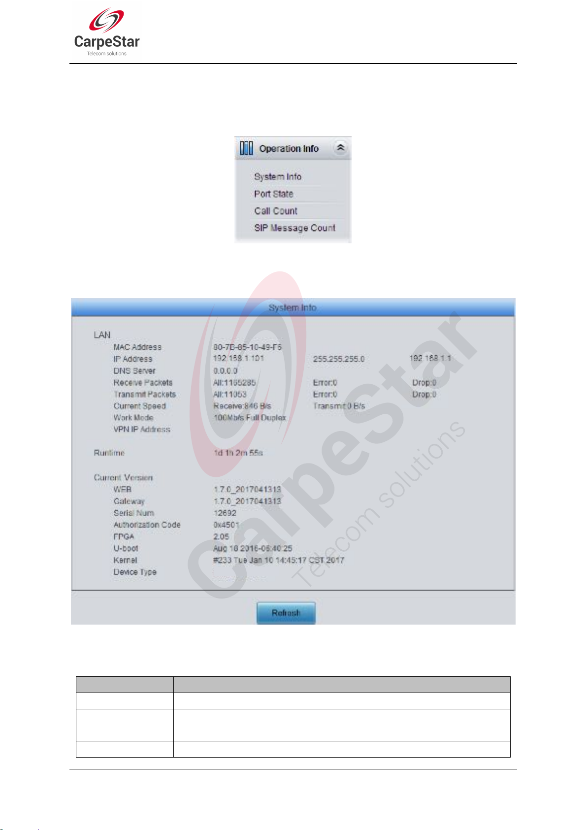
3.2 Operation Info
Item
Description
MAC Address
MAC address of LAN.
IP Address
The three parameters from left to right are IP address, subnet mask and default
gateway of LAN.
DNS Server
DNS server address of LAN.
Operation Info includes four parts: System Info, Port State, Call Count and SIP Message Count,
showing the current running status of the gateway. See Figure 3-3.
Figure 3-3 Operation Info
3.2.1 System Info
Figure 3-4 System Info Interface
See Figure 3-4 for the system info interface. You can click Refresh to obtain the latest system
information. The table below explains the items shown in Figure 3-4.
SMG Series Wireless Gateway User Manual (Version 1.9.0)
Page 13
Receive Packets
The amount of receive packets after the gateway‟s startup, including three options:
All, Error and Drop.
Transmit Packets
The amount of transmit packets after the gateway‟s startup, including three options:
All, Error and Drop.
Current Speed
Show the current speed of data receiving and transmitting.
Work Mode
Show the work mode of the network, including four modes: 10 Mbps Half Duplex, 10
Mbps Full Duplex, 100 Mbps Half Duplex, 100 Mbps Full Duplex.
Runtime
Time of the gateway keeping running normally after startup, which will be
automatically updated.
WEB
Current version of the WEB interface.
Gateway
Current version of the gateway service.
Serial Num
Unique serial number of a wireless gateway.
Authorization Code
The authorization codes vary from different wireless modules.
FPGA
Current version of FPGA.
U-boot
Current version of Uboot.
Kernel
Current version of the system kernel on the gateway.
Device Type
Type of the wireless gateway.
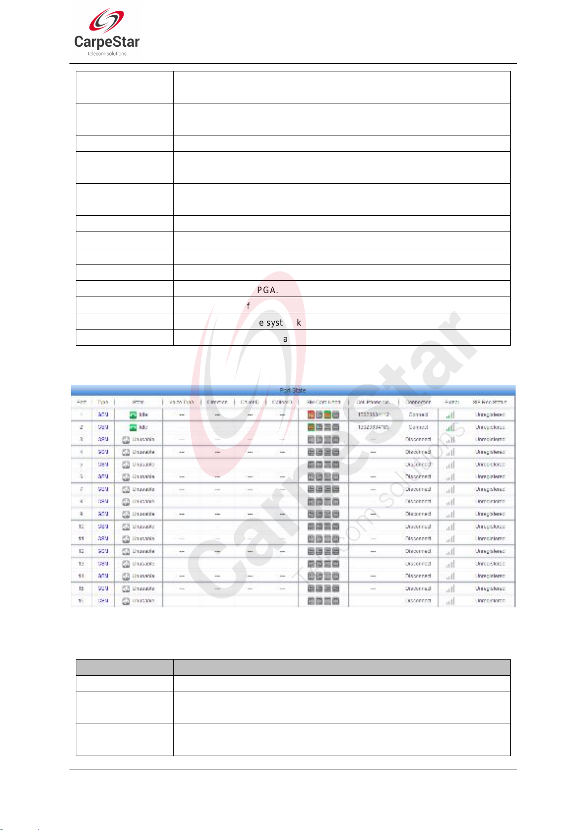
3.2.2 Port State
Item
Description
Port
Port number on the device.
Type
Port type on the device. So far, only GSM, WCDMA, CDMA and LTE types are
supported.
State
Displays the port state in real time. You can move the mouse onto the port state
icon for detailed state information.
Figure 3-5 Channel State Interface
See Figure 3-5 for the channel state interface where shows the channel type, the channel state for
each channel on the gateway. The table below explains the items shown in Figure 3-5.
SMG Series Wireless Gateway User Manual (Version 1.9.0)
Page 14
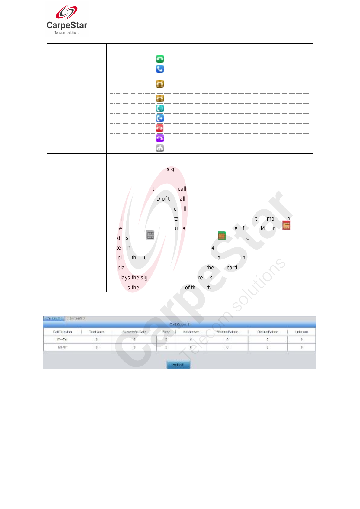
State
Icon
Description
Idle
The port is available.
Off-hook
The port picks up the call.
Wait Answer
The port receives the ringback tone and is waiting for
the called party to pick up the phone.
Ringing
The port is in the ringing state.
Talking
The port is in a conversation.
Dialing
The port is dialing.
Pending
The port is in the pending state.
Internal State
Internal state of the port.
Unusable
The port is unavailable.
Voice Type
Displays the voice type of the current call.
Note: For the LTE series gateway, it is Net type and will display the network type of
the current call.
Direction
Displays the direction of the call on port.
CallerID
Displays the CallerID of the call on port.
CalleeID
Displays the CalleeID of the call on port.
SIM Card
Displays the real-time state of the SIM card. Move the mouse onto the
corresponding icon and you can find the exact state of the SIM card. means
card inserted, means no card inserted, means card in use.
Cell Phone No.
Displays the number of the corresponding channel set in Wireless Parameters.
Connection
Displays the connection status between the SIM card and the base station.
Signal
Displays the signal intensity of the wireless module.
SIP Reg Status
Displays the registration status of the port.
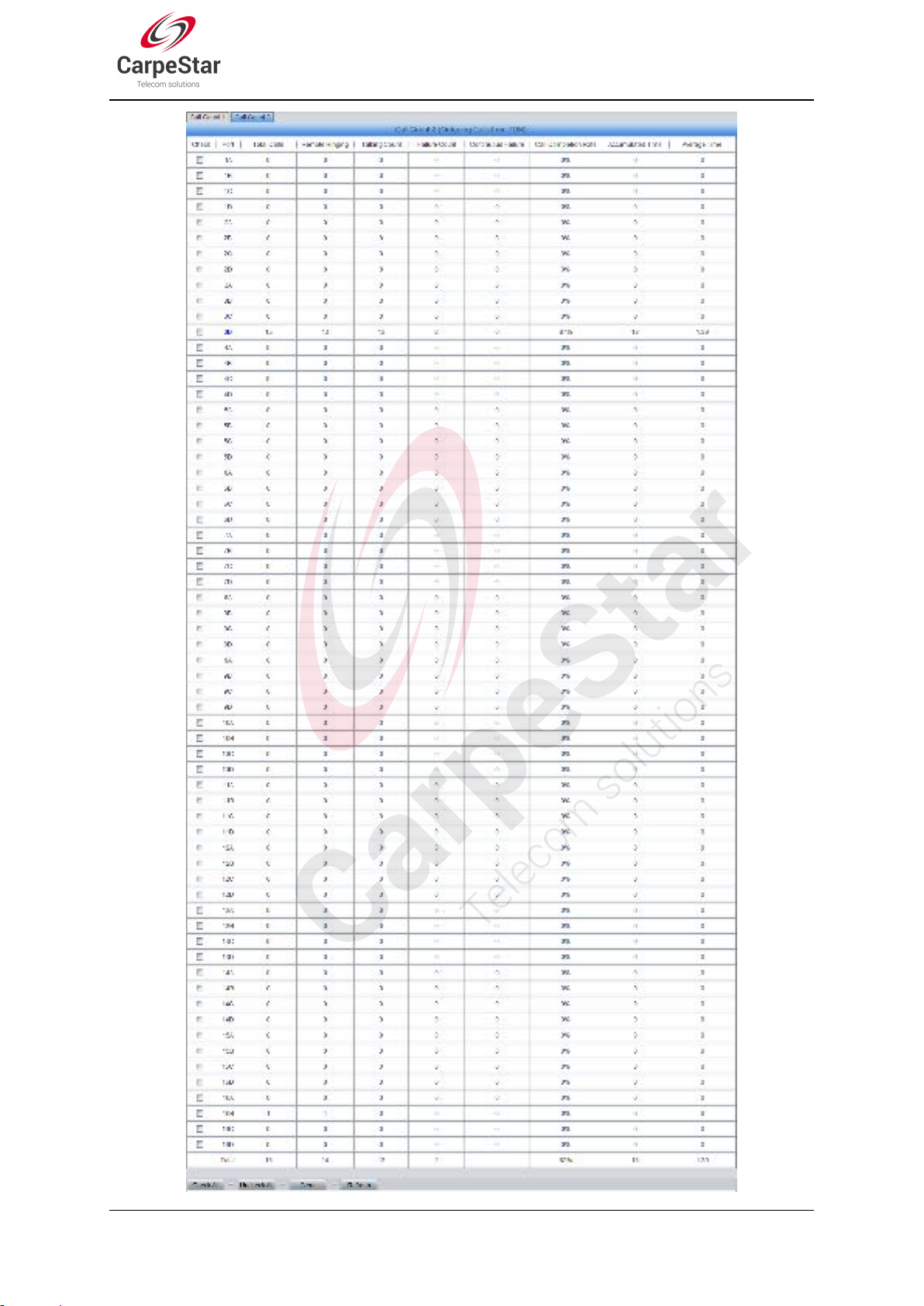
3.2.3 Call Count
Note: This item is unavailable for CMG4004 and CMG4008 series.
Figure 3-6 Call Count 1 Interface
SMG Series Wireless Gateway User Manual (Version 1.9.0)
Page 15

Figure 3-7 Call Count 2 Interface (4004/4008 Series)
SMG Series Wireless Gateway User Manual (Version 1.9.0)
Page 16
Page 17 SMG Series Wireless Gateway User Manual (Version 1.9.0)
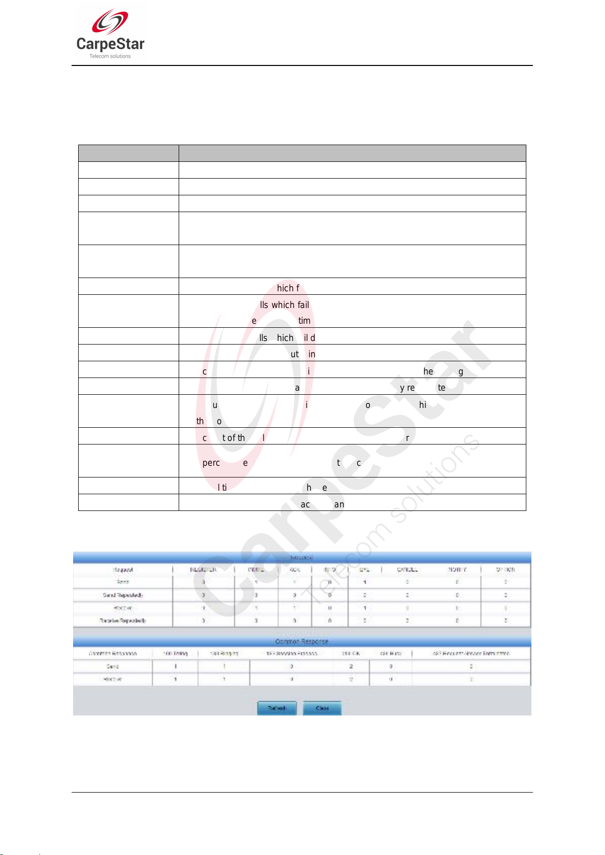
Figure 3-8 Call Count 2 Interface (4016/4032 Series)
Item
Description
Call Direction
A condition for call count, two options available: IPTel and TelIP.
Total Calls
Total number of calls in a specified call direction.
Successful Calls
Total number of successful calls in conversation.
Busy
Total number of calls which fail as the called party has been occupied and replies a
busy message.
No Answer
Total number of calls which fail as the called party does not pick up the call in a long
time or the calling party hangs up the call before the called party picks it up.
Routing Failure
Total number of calls which fail because no routing rules are matched.
Dialing Failure
Total number of calls which fail as the called party number does not conform to the
dialing rule or due to dialing timeout.
Unknown Failure
Total number of calls which fail due to unknown reasons.
Total Calls
The total numbers of the outgoing calls.
Remote Ringing
The count of the calls which bring the remote terminal into the ringing state.
Talking Count
The count of the outgoing calls which are answered by remote terminal.
Failure Count
The count of the failure calls, i.e. the counts of the calls which cannot be made out
by the port.
Continuous Failure
The count of the calls which failed continuously twice or more.
Call Completion
Rate
The percentage of successful calls to total calls.
Accumulated Time
The total time of the calls which are answered by the remote terminal.
Average Time
The average time length of each call answered by the remote terminal.
See Figure 3-6, Figure 3-7 and Figure 3-8 for the call count Interface. The above list shows the
detailed information about all the calls counted from the startup of the gateway service to the
latest open or refresh of this interface. You can click Refresh to obtain the current call count
information. The table below explains the items shown in above figures.
3.2.4 SIP Message Count
Figure 3-9 SIP Message Count Interface
See Figure 3-9 for the SIP Message Count interface. This is used to record the amount of the
normal SIP messages that are sent/received or repeatedly sent/received during the period from
the startup of the gateway service to the latest open or refresh of the interface. Click Refresh to
SMG Series Wireless Gateway User Manual (Version 1.9.0)
Page 18
refresh the count of SIP messages, or click Clear to clear the current count of SIP messages.
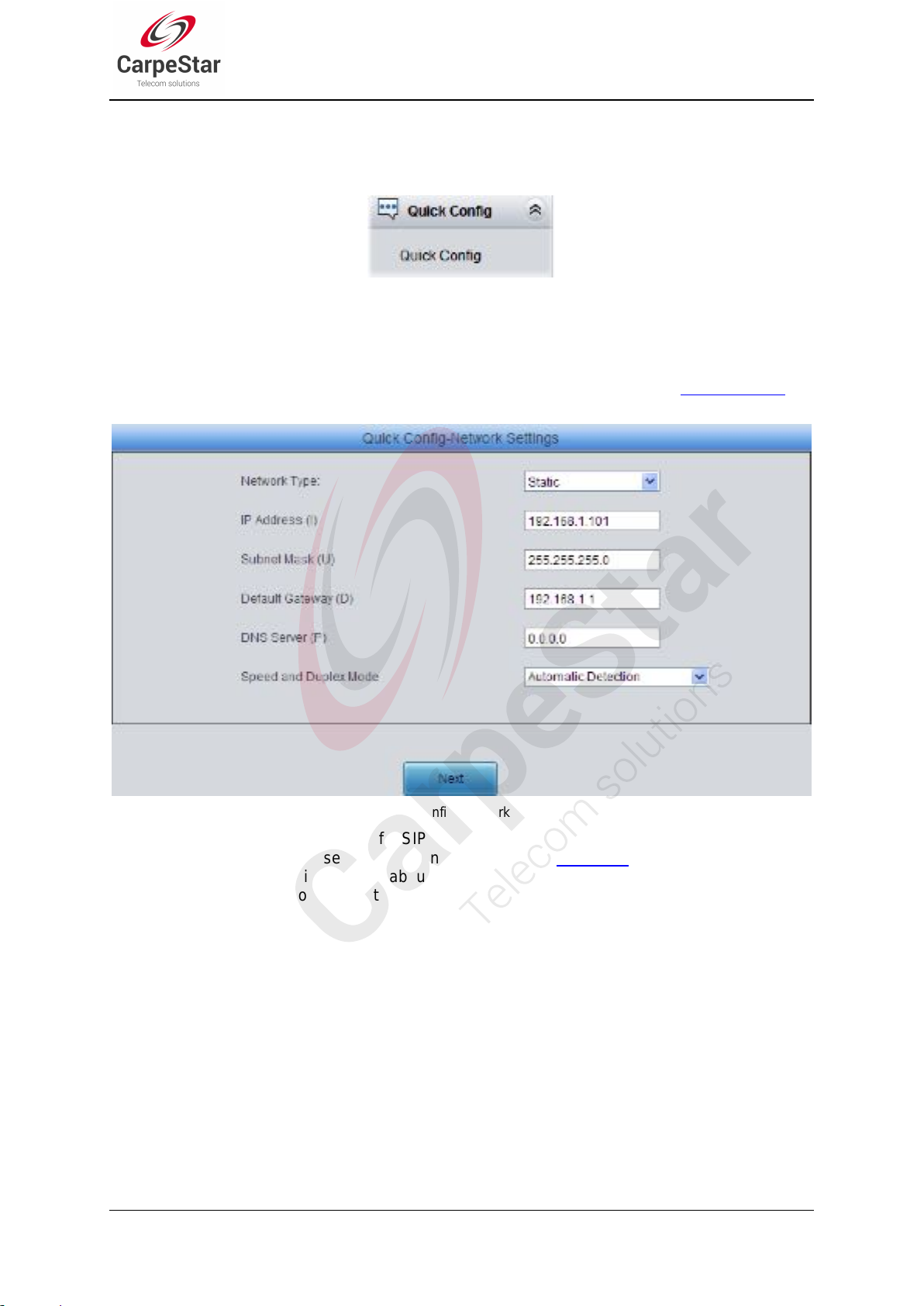
3.3 Quick Config
Figure 3-10 Quick Config Interface
See Figure 3-10 for the Quick Config interface. Follow the gateway Quick Configuration wizard
and you can easily complete the settings on network, SIP and Port. The gateway can work
normally after configuration.
See Figure 3-11 for the Quick Config-Network Settings interface. Refer to 3.5.1 Network for
detailed settings. After configuration, click Next to enter the SIP Settings interface.
Figure 3-11 Quick Config-Network Settings Interface
See Figure 3-12 for the Quick Config-SIP Settings interface. The configuration items on this
interface are the same as those on the SIP interface. Refer to 3.4.1 SIP for detailed settings. You
are required to fill with the information about the registrar if the gateway must be registered. After
configuration, click Back to go back to the Network Settings interface; click Next to enter the Port
Settings interface.
SMG Series Wireless Gateway User Manual (Version 1.9.0)
Page 19
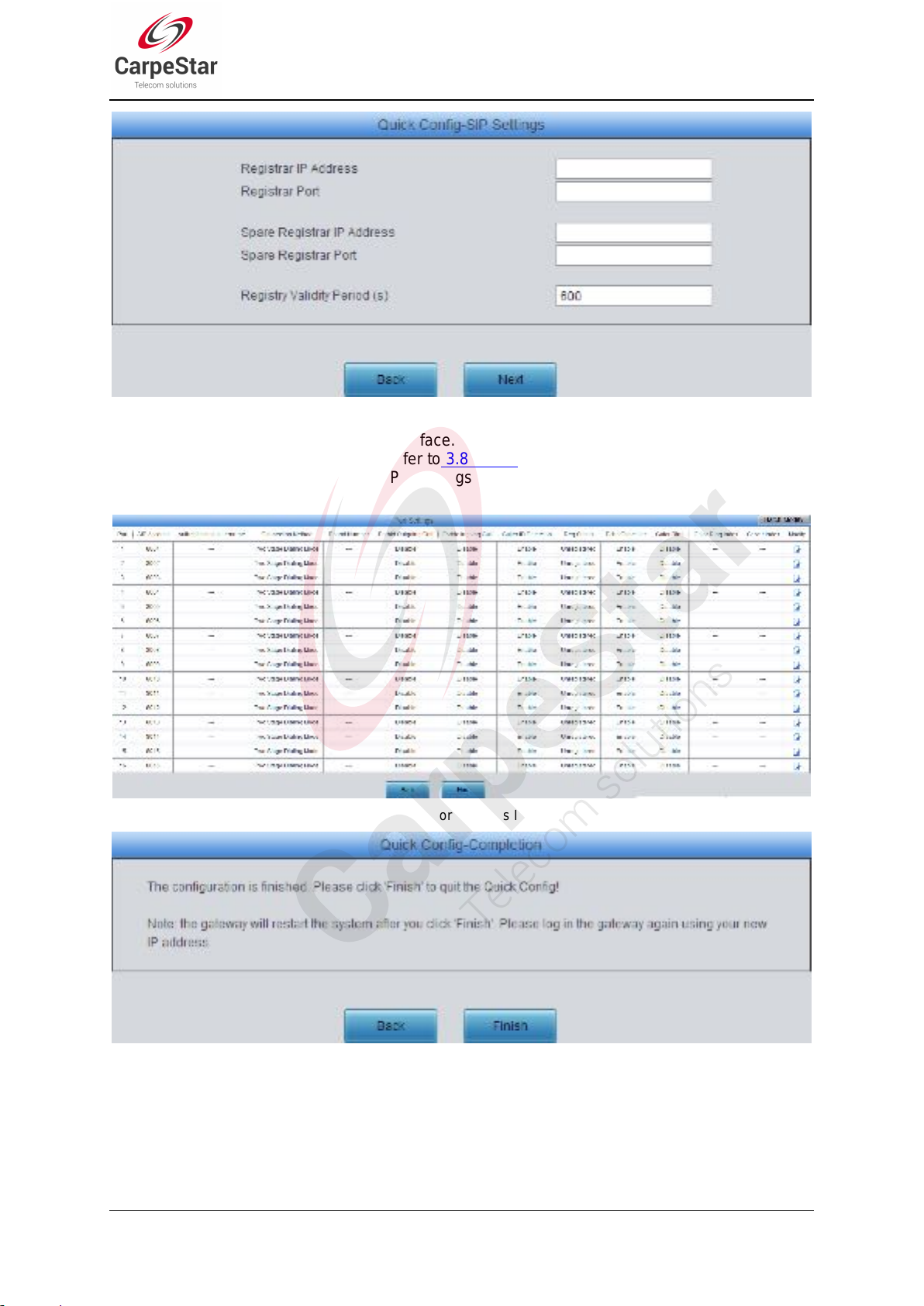
Figure 3-12 Quick Config-SIP Settings Interface
See Figure 3-13 for the Port Settings interface. The configuration items on this interface are the
same as those on the Port interface. Refer to 3.8.1 Port for detailed settings. After configuration,
click Back to go back to the SIP Settings interface; click Next to enter the Quick
Config-Completion interface.
Figure 3-13 Port Settings Interface
Figure 3-14 Quick Config-Completion Interface
Click Back to go back to the Port Settings interface; click Finish to finish the Quick Config wizard
and now the gateway can work normally with basic configuration.
SMG Series Wireless Gateway User Manual (Version 1.9.0)
Page 20
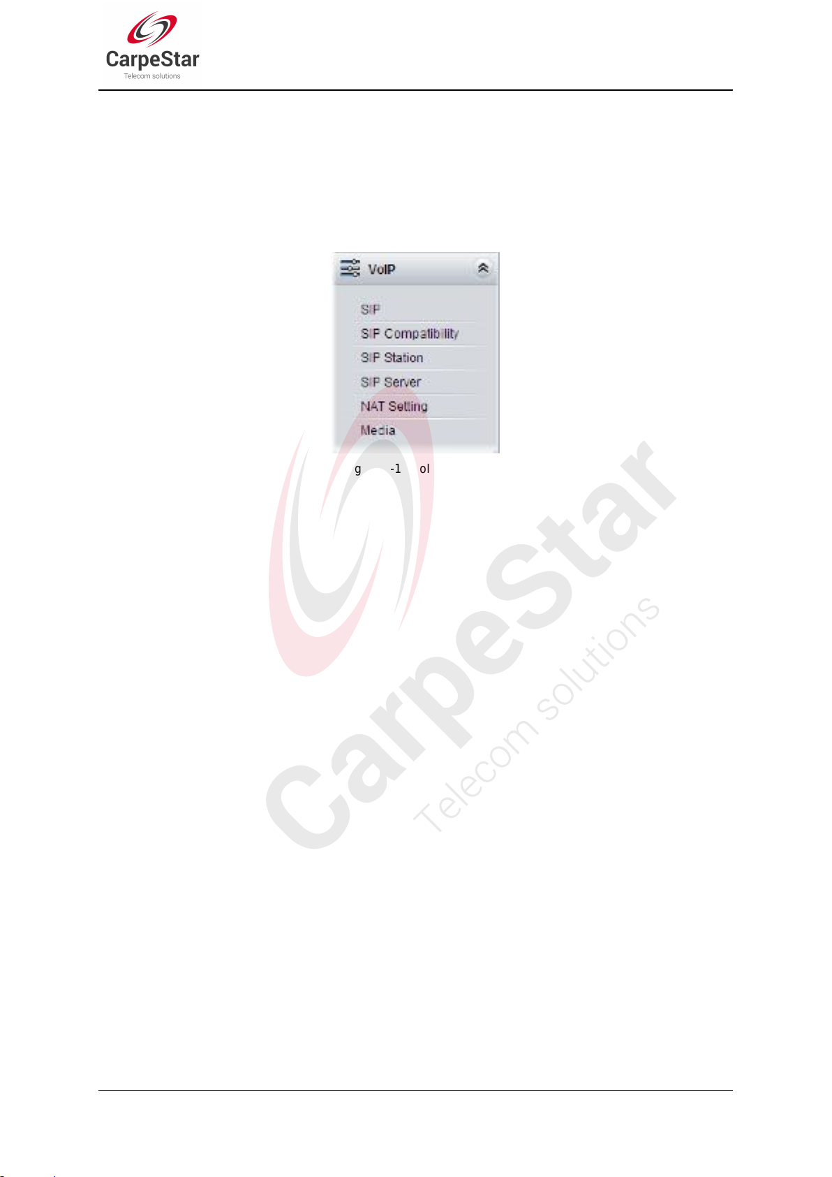
3.4 VoIP Settings
VoIP Settings includes six parts: SIP, SIP Compatibility, SIP Station, SIP Server, NAT Setting
and Media. See Figure 3-15. SIP Settings is used to configure the general SIP parameters, SIP
Compatibility is used to set which SIP servers and SIP messages will the gateway be compatible
with, SIP Station is to set the basic information of the SIP station, SIP Server is to set the basic
information of the SIP server, NAT Setting is used to configure the parameters for NAT, and
Media Settings is to set the RTP port and the payload type.
Figure 3-15 VoIP Settings
SMG Series Wireless Gateway User Manual (Version 1.9.0)
Page 21
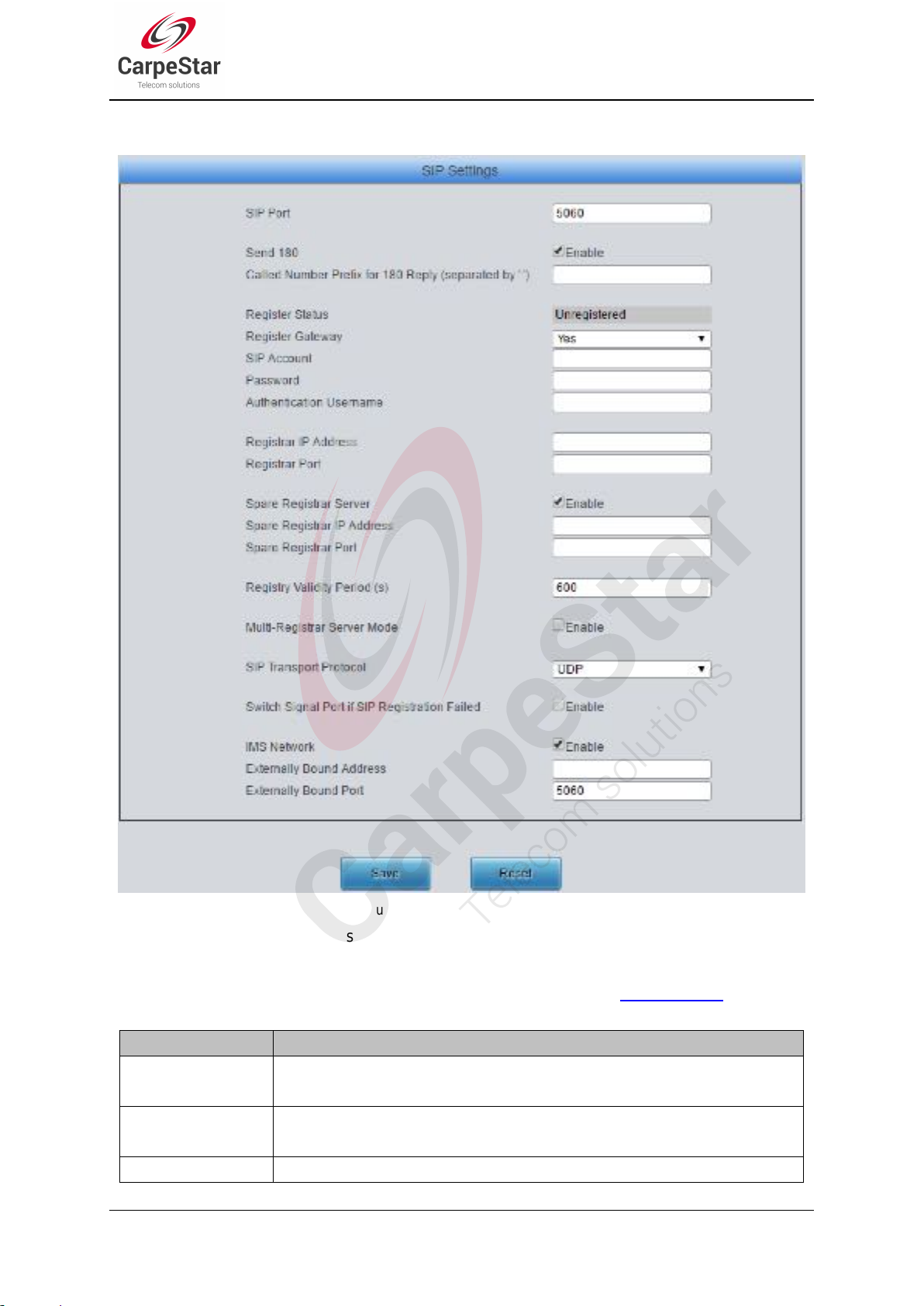
3.4.1 SIP
Item
Description
SIP Port
Monitoring port of SIP signaling. The value range of it must be greater than 1024
and less than 65535, with the default value of 5060.
Send 180
Sets whether to send the 180 message to respond to the ringing tone when the SIP
end serves as the called party.
Called Number
Once the feature “Send 180” is enabled, the gateway will reply the 180 message to
Figure 3-16 SIP Settings Interface
See Figure 3-16 for the SIP settings interface where you can configure the general SIP
parameters. After configuration, click Save to save your settings into the gateway or click Reset to
restore the configurations. If a dialog box pops up after you save your settings asking you to
restart the system, do it immediately to apply the changes. Refer to 3.11.9 Restart for detailed
instructions. The table below explains the items shown in Figure 3-16.
SMG Series Wireless Gateway User Manual (Version 1.9.0)
Page 22
Prefix for 180 Reply
those calls which have the calleeID with the designated prefix; otherwise, it will
reply the 183 message. By default, the value is null, that is, replying the 183
message to all calls.
Register Status
Registration status of the gateway. When Register Gateway is set to No, the value
of this item is Unregistered; when Register Gateway is set to Yes, the value of this
item is either Failed or Registered.
Register Gateway
Sets whether to register the gateway as a whole. The default value is No. Only
when this configuration is set to Yes can you see the configuration items SIP
Account and Password.
SIP Account
When the gateway initiates a call to SIP, this item corresponds to the username of
SIP.
Password
Registration password of the gateway. To register the gateway to SIP, both
configuration items SIP Account and Password should be filled in.
Authentication
Username
Authentication username for registration.
Registrar IP Address
Address of the registry server for the gateway to register.
Registrar Port
Signaling port of the registry server.
Spare Registrar
Server
Check the enable checkbox to enable the spare registrar server. By default, it is
disabled.
Spare Registrar IP
Address
Address of the spare registry server for the gateway to register. The gateway will
enable the spare registrar server if the master registrar server has no reply, or the
master server is detected with no response in case the item Detection Server
Cycle is enabled.
Spare Registrar Port
Signaling port of the spare registry server.
Registry Validity
Period
Validity period of the SIP registry. Once the registry is overdue, the gateway should
be registered again. This configuration item is valid only when Register Gateway is
set to Yes. Range of value: 10~3600, calculated by s, with the default value of 600.
Multi-Registrar
Server Mode
Tick the checkbox before to enable the multi-registrar server mode. By default, it is
disabled.
SIP Transport
Protocol
There are two modes UDP and TCP available for running the SIP protocol. The
default value is UDP.
Switch Signal Port if
SIP Registration
Failed
If the SIP registration fails, the SIP signaling port N will switch to N+1 for a new
registration. It will continue until the registration succeeds. By default, it is disabled.
IMS Network
Once this feature is enabled, the gateway will send signaling messages to the
corresponding externally bound address and port when it registers to the server. By
default, this feature is disabled. Only when this feature is enabled will these items
Externally Bound Address, Externally Bound Port and Authentication
Username be shown.
Externally Bound
Address
Externally bound IP address for registration.
Externally Bound
Port
Externally bound port for registration.
SMG Series Wireless Gateway User Manual (Version 1.9.0)
Page 23

3.4.2 SIP Compatibility
Item
Description
Obtain CalleeID
There are two optional ways to obtain the called party number: from “To” Field and
See Figure 3-17 for the SIP Compatibility interface where you can configure the SIP parameters
to determine which SIP servers and SIP messages will the gateway be compatible with. After
configuration, click Save to save your settings into the gateway or click Reset to restore the
configurations.
Figure 3-17 SIP Compatibility Setting Interface
The table below explains the items shown in Figure 3-17.
SMG Series Wireless Gateway User Manual (Version 1.9.0)
Page 24
 Loading...