


V3
Instruction Manual
Models
EP2020-000 EP4020-000
EP2040-000 EP4040-000
EP2060-000 EP4060-000
EP2075-000 EP4075-000
EP2100-000 EP4100-000
EP2125-000 EP4125-000
EP2150-000 EP4150-000
EP2200-000 EP4200-000
EP2250-000 EP4250-000
EP2300-000 EP4300-000
EP2400-000 EP4400-000
EP2500-000 EP4500-000
EP2600-000 EP4600-000
EP2700-000 EP4700-000

Table of Contents
1. General Description .......................................................................................................................................... 4
2. Specifications ....................................................................................................................................................4
2.1 Electrical.............................................................................................................................................4
2.2 Physical..............................................................................................................................................5
3. Installation .........................................................................................................................................................7
3.1 Control Installation .............................................................................................................................7
3.2 Wiring Guidelines ............................................................................................................................... 7
4. Terminal Connections & Functions ................................................................................................................... 7
4.1 AC Power Connections & Fusing.......................................................................................................7
4.2 Motor Connections ............................................................................................................................. 9
4.3 Signal Connections .......................................................................................................................... 11
5. Human Machine Interface (HMI) ..................................................................................................................... 14
5.1 Description of Interface .................................................................................................................... 14
5.2 Menu Structure.................................................................................................................................15
6. Start Up Procedure ......................................................................................................................................... 17
6.1 Pretest..............................................................................................................................................17
6.2 Adjustment Procedure: Velocity (Speed) Regulator.........................................................................17
6.3 Adjustment Procedure: Constant Horsepower................................................................................. 19
6.4 Adjustment Procedure: Torque (Current) Regulator........................................................................ 19
6.5 Calibration & Fine Tuning.................................................................................................................19
6.4 Password Protection ........................................................................................................................ 21
7. Programming & Adjustments .......................................................................................................................... 22
7.1 A: Options ........................................................................................................................................22
7.2 B: Digital Inputs ................................................................................................................................ 23
7.3 C: Analog Inputs...............................................................................................................................29
7.4 D: Digital Outputs ............................................................................................................................. 34
7.5 E: Analog Outputs ............................................................................................................................ 38
7.6 F: Motor Data ................................................................................................................................... 40
7.7 G: Control Loops .............................................................................................................................. 44
7.8 H: Start/Stop Logic ........................................................................................................................... 52
7.9 I: Setpoints ....................................................................................................................................... 56
7.10 J: Ramps ........................................................................................................................................ 58
7.11 K: Fault Logic ................................................................................................................................. 62
7.12 L: Applications................................................................................................................................68
7.13 M: Thresholds ................................................................................................................................78
7.14 N: Timers .......................................................................................................................................81
7.15 O: Logic Gates ............................................................................................................................... 83
7.16 P: Switches ....................................................................................................................................86
7.17 Q: Internal Links ............................................................................................................................. 87
7.18 R: Communications........................................................................................................................88
7.19 S: Zero Speed ................................................................................................................................ 91
7.20 T: System ....................................................................................................................................... 92
7.21 U: Auxiliary ..................................................................................................................................... 94
7.22 Parameter Table ............................................................................................................................95
8. Troubleshooting ............................................................................................................................................ 109
9. Serial Network Communications ...................................................................................................................113
9.1 Physical..........................................................................................................................................113
9.2 Modbus® Protocol..........................................................................................................................113
10. Spare Parts ................................................................................................................................................. 115
10.1 Printed Circuit Assemblies ........................................................................................................... 115
10.2 Fuses ...........................................................................................................................................115
10.3 Power Components......................................................................................................................117
11. Prints ...........................................................................................................................................................118
D14171 Control Board Assembly.........................................................................................................118
D14163 Trigger Board Assembly ......................................................................................................... 119
D14177 Regulator Board Assembly.....................................................................................................120
C14188 Snubber Board Assembly.......................................................................................................121
C14166 CT ID Board Assembly ........................................................................................................... 122
C14045 Processor Board Assembly .................................................................................................... 123
2

D14270 Assembly Drawing, 20-60HP Models .....................................................................................124
D14316 Assembly Drawing, 75-150HP Models ...................................................................................125
DXXXXX Assembly Drawing, 200-400HP Models...............................................................................126
D14356 Assembly Drawing, 500-700HP Models .................................................................................127
D14263 Assembly, Heatsink Chassis, 20-60HP Non-Regen Models ..................................................128
D14264 Assembly, Heatsink Chassis, 20-60HP Regen Models..........................................................129
D14347 Assembly, Heatsink Chassis, 75-150HP Non-Regen Models ................................................130
D14318 Assembly, Heatsink Chassis, 75-150HP Regen Models........................................................131
DXXXXX Assembly, Heatsink Chassis, 200-300HP Non-Regen Models............................................132
DXXXXX Assembly, Heatsink Chassis, 400HP Non-Regen Model.....................................................133
DXXXXX Assembly, Heatsink Chassis, 200-300HP Regen Models....................................................134
DXXXXX Assembly, Heatsink Chassis, 400HP Regen Model.............................................................135
D14350 Assembly, Heatsink Chassis, 500-700HP Non-Regen Models ..............................................136
D14351 Assembly, Heatsink Chassis, 500-700HP Regen Models......................................................137
D14248 Wiring Diagram, 20-60HP Non-Regen Models ......................................................................138
D14249 Wiring Diagram, 20-60HP Regen Models .............................................................................. 139
D14322 Wiring Diagram, 75-150HP Non-Regen Models ....................................................................140
D14314 Wiring Diagram, 75-150HP Regen Models ............................................................................ 141
DXXXXX Wiring Diagram, 200-400HP Non-Regen Models ................................................................142
DXXXXX Wiring Diagram, 200-400HP Regen Models ........................................................................ 143
D14353 Wiring Diagram, 500-700HP Non-Regen Models ..................................................................144
D14354 Wiring Diagram, 500-700HP Regen Models .......................................................................... 145
D14308 General Connections..............................................................................................................146
D14306 RS422/485 Network Connections ..........................................................................................147
C14307 Sonic Transducer Option Connections...................................................................................148
D14309 Software Block Diagram .........................................................................................................150
12. Standard Terms & Conditions of Sale .........................................................................................................155
List of Tables
Table 1: Model Rating Data...................................................................................................................................9
Table 2: HMI Description.....................................................................................................................................14
Table 3: Drive Monitor Descriptions ....................................................................................................................16
Table 4: Common Digital Input Functions ...........................................................................................................23
Table 5: Common Analog & Freq Input Functions ..............................................................................................29
Table 6: Analog Input Status Readings...............................................................................................................30
Table 7: Common Relay & Digital Output Functions...........................................................................................34
Table 8: Common Analog & Freq Output Functions ...........................................................................................38
Table 9: Analog Output Status ............................................................................................................................39
Table 10: Drive Modes ........................................................................................................................................54
Table 11: Reference Select.................................................................................................................................56
Table 12: Faults 1................................................................................................................................................64
Table 13: Faults 2................................................................................................................................................64
Table 14: Alarms 1 ..............................................................................................................................................65
Table 15: Inertia Sensitivity .................................................................................................................................75
Table 16: Logic Gates Truth Table......................................................................................................................85
Table 17: Parameters..........................................................................................................................................95
Table 18: Faults.................................................................................................................................................109
Table 19: Supported Modbus® Functions.........................................................................................................114
Table 20: Field Fuses........................................................................................................................................115
Table 21: Recommended Line Fuses ...............................................................................................................116
Table 22: Armature Bridge Modules .................................................................................................................117
Table 23: Field Supply Modules ........................................................................................................................117
3

1111
General Description
The Elite Pro V3 Series is Carotron's 3rd generation of microprocessor based D.C. motor controls.
The series provides control of speed and torque control of 5-700HP D.C. motors rated for NEMA
type "C" power supplies. The EP2 (non-regenerative) series and the EP4 (regenerative) series are
offered in compact panel mounted assemblies.
2222
Specifications
2.1 Electrical
A.C. Input Voltage Range
•
3 phase, 230-460 VAC ± 10%, 50/60 Hz ± 2 Hz
•
1 phase, 115 VAC ± 10%, 50/60 Hz ± 2 Hz, 5A
A.C. Line Field Supply - 1 Phase (Optional)
•
230-460 VAC ± 10%, 50/60 Hz ± 2 Hz
Armature Output
•
0-240VDC @ 230 VAC input
•
0-415VDC @ 380 VAC input
•
0-500VDC @ 460 VAC input
Field Output
•
Voltage
0-200VDC @ 230 VAC input
0-330VDC @ 380 VAC input
0-400VDC @ 460 VAC input
•
Current
EPx020-000 thru EPx060-000: 8A max
EPx075-000 thru EPx150-000: 10A max
EPx200-000 thru EPx700-000: 12A max
Power Supplies
•
+24V (TB1-1): 50mA
•
+12V (TB1-17): 100mA
•
+10V (TB1-16): 50mA
•
-10V (TB1-46): 50mA
Digital Inputs (Qty: 7)
•
Sink Mode
Vih=20.0 VDC max
Vil=0.0 VDC min to 17.0 VDC max
•
Source Mode
Vih=8.0 VDC min to 30.0 VDC max
Analog Inputs (Qty: 5)
•
•
Max Input: ±20 mADC
•
Tachometer Feedback Input
•
Vil=5.0 VDC max
Voltage Mode
Max Input:±10 VDC
Input Impedance: 1MΩ
Current Mode
Input Impedance: 250Ω
Resolution: 12 bit
Max Input: ±200 V (AC or DC)
Encoder Feedback Input
•
Frequency: 200kHz max
•
Uni-directional (single channel) or Quadrature
•
Single ended or differential
•
Voltage: 12 VDC max
Frequency Input
•
Frequency: 40kHz max, square wave
•
Voltage: 12 VDC max
Vil=0.0 VDC to 1.5 VDC max
Relay Outputs (Qty: 3)
Form-C contact:
•
•
Armature Pilot Relay Output
•
•
Analog Outputs (Qty: 2)
•
•
Frequency/Digital Output
•
•
•
Speed Regulation
•
•
•
Torque Regulation
•
Speed Range
•
Temperature Range
•
•
Vih=2.5 VDC min to 12.0 VDC max
2 A @ 115 VAC (resistive)
2 A @ 60 VDC (resistive)
30 A @ 120 VAC (resistive)
30 A @ 28 VDC (resistive)
±10 VDC max, 20mADC max
Resolution: 12 bit + sign
Frequency: 10kHz max, square wave
Sink current: 100mA max
Voltage: 30VDC max
Armature Feedback: ±1%
Tachometer Feedback: ±0.01%
Encoder Feedback: ±0.01% (with 1024 min ppr)
±1% of Range Selected
100:1 typical when using tachometer or encoder
feedback. May be less depending upon motor
characteristics
Chassis: 0-55C
Enclosed: 0-40C
4
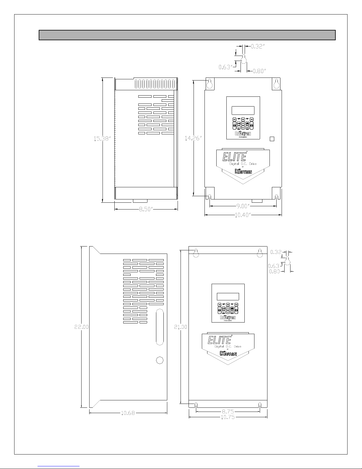
2.2 Physical
PRO
EPx020-000 thru EPx060-000
PRO
EPx075-000 thru EPx150-000
5

PRO
PRO
6

3333
Installation
3.1 Control Installation
Elite Pro motor controls require mounting in an upright position in an area that will permit adequate
airflow for cooling and ready access for making connections and for servicing. Because cooler air is
drawn in from the bottom and exhausted from the top, these areas should be kept clear for about a
six inch distance. Stacking of controls with one mounted above the other should be minimized so that
the upper control is not ventilated with hot exhaust air from the lower control.
Enclosures should be sized to provide adequate surface area for dissipating heat or provided with
forced ventilation with outside air from a duct system or enclosure fan. They should be mounted to a
cool surface not exposed to heat generated by nearby equipment.
Excess ambient temperatures within enclosures can reduce the life expectancy of electronic
components and can cause a heatsink over temperature fault on the Elite Pro control. Contact
Carotron for assistance in sizing enclosures for particular horsepower ratings.
3.2 Wiring Guidelines
To prevent electrical interference and to minimize start-up problems, adhere to the following
guidelines.
Make no connections to ground other than the designated terminal strip location.
Use fully insulated and shielded cable for all signal wiring. The shield should be connected at one
end only to circuit common. The other end of the shield should be clipped and insulated to prevent
the possibility of accidental grounding.
Signal level wiring such as listed above should be routed separately from high level wiring such as
armature, field, and relay control wiring. When these two types of wire must cross, they should cross
at right angles to each other.
Any relays, contactors, starters, solenoids or electro-mechanical devices located in close proximity to
or on the same line supply as the motor control should have a transient suppression device such as
an MOV or R-C snubber connected in parallel with its coil (for AC coils). Diode suppression should
be used for DC coils. The suppressor should have short leads and should be connected as close to
the coil as possible.
4444
Terminal Connections & Functions
4.1 AC Power Connections & Fusing
Terminals L1, L2, and L3 are the AC line inputs for the armature power bridge. High speed
semiconductor fuses must be provided externally. Refer to Figure 1 and Figure 2 on the next page
and Table 21 in the Spare Parts Section on page 116 for common manufacturers and part numbers.
In most cases, the drive will use the internal field supply wiring scheme (Figure 1). The field bridge
is powered from the auxiliary L1 and L2 output terminals via factory installed jumpers. However, in
some cases, the field voltage required by a motor exceeds the maximum obtainable field voltage that
can be produced using the required AC line voltage for the motor armature. In these cases, an
external single phase AC supply for the field bridge must be used. The factory supplied terminal
jumpers should be removed and the external supply connects to FL1 and FL2 (Figure 2). Note the
external supply must be in phase with the L1 and L2 armature supply terminals.
7
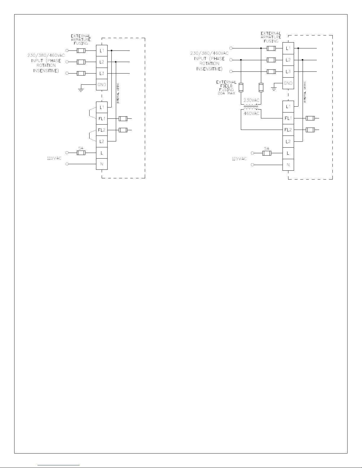
Figure 1: Internal Field Supply Wiring
For example, consider the motor that has a rated armature voltage of 240VDC and a rated field of
240VDC. The rated armature voltage requires that an input supply of 230VAC be connected to L1,
L2, and L3. However, the maximum field voltage attainable from the field bridge using the internal
supply would be 200VDC. In order to obtain the required 240VDC field, an external single phase
460VAC supply (obtained via a transformer) can be connected to FL1 and FL2.
The drive also requires a fused single phase 115VAC control power on terminals L and N.
Carotron recommends the use of three phase DIT, drive isolation type transformers. While Elite Pro
controls do not require these transformers for proper operation, they can be helpful in reducing the
effects of line transients on this control and generated by this control on other products and can
provide fault current limiting in the event of severe motor or control failure. Refer to Table 1 as a
general guide in sizing line supply transformers and wiring.
Figure 2: External Field Supply Wiring
8

Drive
Model
EPx020-000
EPx040-000
EPx060-000
EPx075-000
EPx100-000
EPx125-000
EPx150-000
EPx200-000
EPx250-000
EPx300-000
EPx400-000
EPx500-000
EPx600-000
EPx700-000
x=2 for non-regenerative models
x=4 for regenerative models
Arm
Volts
240
500
240
500
240
500
240
500
240
500
240
500
240
500
240
500
240
500
240
500
240 200 220
500 400
240 250 275
500 500
240 300 330
500 600
240 350 385
500 700
Motor
HP
5 18 7.5 18 10Ω, 300W
7.5 26 11 28.1 5Ω, 600W
10 34 14 36
5 9 7.5 8.5 40Ω, 375W
7.5 14 11 13.2 20Ω, 750W
10 18 14 17.2 20Ω, 750W
15 25 20 25.2 14Ω, 1000W
20 34 27 36
15 50 20 55 3Ω, 1000W
20 65 27 71
25 40 34 43 7Ω, 2000W
30 47 40 51 6Ω, 2000W
40 63 51 71
25 84 34 91.1
30 98 40 107
50 78 63 83.7
60 93 75 107
40 118 51
75 106 93
50 148 63
100 141 118
60 174 75
125 177 145
75 93
150
100 118 360 Amps 0.47Ω, 4700W
200
125 145 535 Amps 0.37Ω, 5300W
250
150 175 535 Amps 0.31Ω, 7000W
300
Approx. Full Load
Line Amps
213
283
354
426
555
694
832
950
3 Phase DIT
KVA Rating
175
220
275
330
440
550
660
770
Table 1: Model Rating Data
Arm
Amps
140
174
206
256
340
425
510
688
850
1020
1165
Contactor
Rating
40 Amps
40 Amps
75 Amps
75 Amps
110 Amps
110 Amps
180 Amps
180 Amps
180 Amps
180 Amps
260 Amps
260 Amps
260 Amps
260 Amps 1.24Ω, 4464W
360 Amps 1.02Ω, 6500W
535 Amps 0.82Ω, 11000W
535 Amps 0.65Ω, 14600W
Consult
Factory
Consult
Factory
Consult
Factory
Consult
Factory
D.B. Resistor
Rating
4.4Ω, 750W
10Ω, 1500W
2.2Ω, 1500W
5Ω, 3000W
1.7Ω, 2000W
3.4Ω, 4000W
1.3Ω, 2080W
2.6Ω, 4160W
0.62Ω, 2232W
1.24Ω, 4464W
0.62Ω, 2232W
1.24Ω, 4464W
0.62Ω, 2232W
Consult
Factory
Consult
Factory
Consult
Factory
Consult
Factory
4.2 Motor Connections
Field
Most motor fields consist of two windings that are connected in parallel for low voltage operation and
in series for high voltage operation. Refer to Figure 3. The winding leads are individually marked
and have a polarity that must be observed for proper and safe operation. Since direction of rotation is
controlled by field polarity as well as armature polarity, it is sometimes more convenient to swap the
smaller field leads when making corrections to the direction of rotation during initial installation. An
energized field should never be switched by relay, contactor, switch or any other manual or electromechanical device.
In most cases, when the Elite Pro is supplied with 230VAC, the field should be wired for low voltage
operation. When supplied with 460VAC, the motor field is typically wired for high voltage operation.
The F1 and F3 leads should always have the same polarity regardless of the mode used.
9

Figure 3
Armature
The armature leads are usually the highest current wires associated with the drive and warrant
special attention to sizing based on current rating as well as length of run. Extra care should be used
where terminations and splices are made. Refer to Table 1 for typical armature voltage, current,
contactor and dynamic braking resistor ratings. Figure 4 shows a typical armature wiring scheme
using a contactor. An optional dynamic breaking resistor is also shown.
Figure 4
Series Field
When present, the S1 and S2 for the SERIES field winding is placed in series with the armature
leads on non-regenerative models only! They should NOT be used with the EP4 Series
regenerative models. On regenerative models, the leads should not be connected and should be
individually insulated. On non-regenerative models the series field winding polarity must be kept at
the same polarity as the shunt field winding, i.e. F1 and S1 the same, F2 (or F4) and S2 the same. If
during startup the field windings are reversed to change direction of the motor, the series windings
should also be reversed to maintain the proper polarity. Figure 5 shows a typical wiring scheme
using the series field with a non-regenerative drive. Note the polarity of the shunt field and series
field windings (S1 is positive with respect to S2, F1 is positive with respect to F2).
10

Figure 5
Motor Thermostat
Most motors include "J" or "P" leads that connect to an internal normally closed thermostat.
Connecting the thermostat to TB1-38 & 39 as shown in Figure 6 will allow a motor over-temperature
condition to shut down the control as in an Emergency Stop condition. If the motor does not provide
a thermostat or the thermostat wiring is not used, a jumper must be placed across terminals 38 & 39.
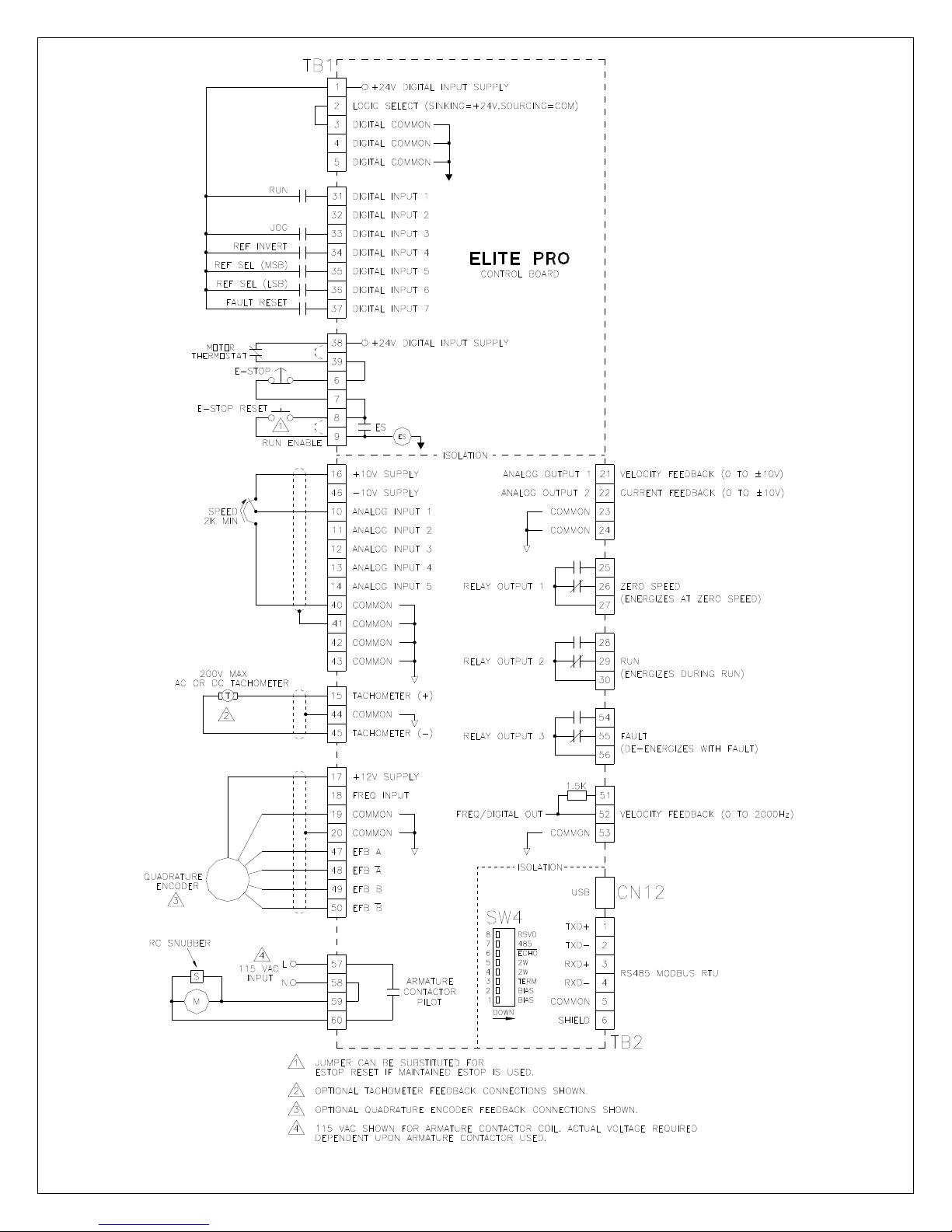
4.3 Signal Connections
Figure 6 shows the typical signal connections to an Elite Pro drive. When operated, the Emergency
Stop contacts at terminals 6 and 7 will immediately clamp all control signals. The armature contactor
will also de-energize to disconnect the armature from the bridge output. Motor stopping time is
determined by inertia and friction characteristics of the load and can be decreased by use of a brake
resistor. Refer to Table 1 for recommended resistor values. If a maintained Emergency Stop pushbutton is used, the E-Stop Reset contacts at TB1-8 & 9 can be jumpered. Otherwise, a momentary
push-button can be used to reset the E-Stop condition.
11
12
Figure 6: Signal Connections
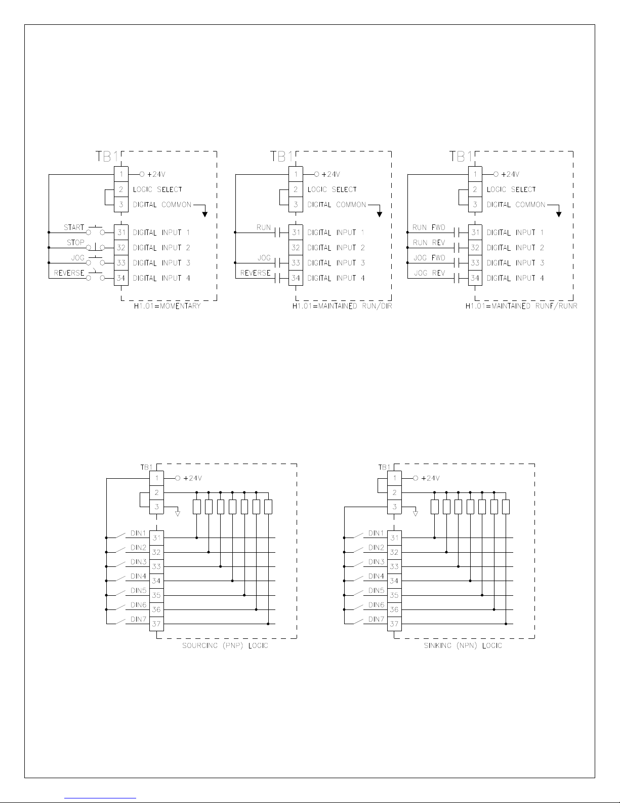
The Elite Pro V3 supports three different start/stop logic schemes (four including the local mode).
Refer to Figure 7 below. The momentary scheme (often called 3 wire) uses momentary pushbuttons
to control the starting and stopping of the drive. A selector switch or a contact controls the direction.
The other two schemes use maintained contacts (often called 2 wire mode). In the Run/Direction
scheme, a single contact starts and stops the drive. Another contact selects direction. In the final
scheme, each contact starts the drive and selects the direction. Parameter H1.01 needs to be set
appropriately.
Figure 7
The drive also has the capability to interface with either sinking or sourcing logic controls. Sourcing
(PNP) logic is selected by jumpering TB1 terminals 2 & 3. This places an internal pull down resistor
on each input. The external switch or sensor must then drive the input high to activate the input.
Sinking (NPN) logic is selected by jumpering TB1 terminals 1 & 2. This places an internal pull up
resistor on each input. The external switch or sensor must then sink (pull down) the input to common
to activate the input.
Figure 8
13
5555
Human Machine Interface (HMI)
5.1 Description of Interface
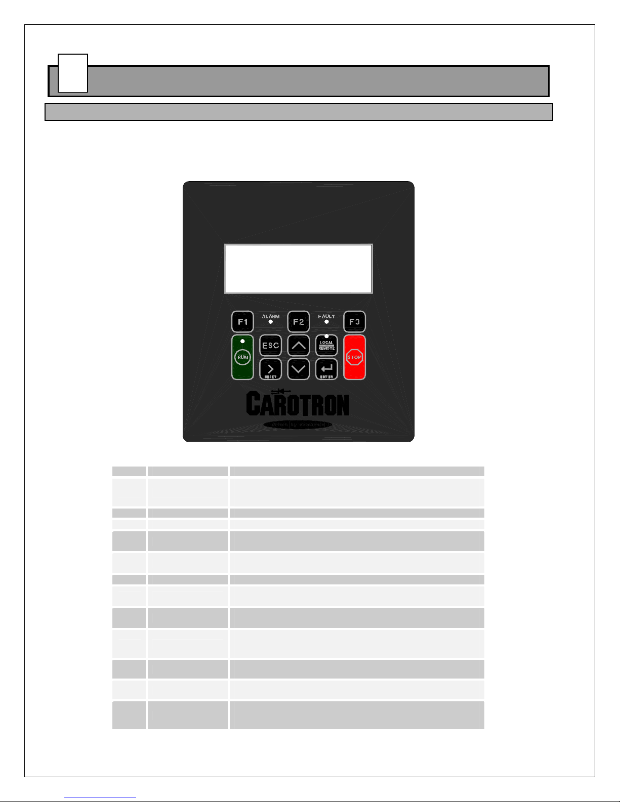
The Human Machine Interface (HMI) is the primary method for accessing the drive's parameters. It
allows for custom user configuration, monitoring, and troubleshooting. As seen in Figure 9, the HMI
consists of a 4 line by 20 characters display, 11 button keypad, and 4 LEDs.
DM01: ELITE PRO V3
REFERENCE: 12.34%
SPEED: 0.00%
STATUS: STOP
Figure 9
Index Item Description
1 F1-F3
2 Run Key Places the drive in run mode when in local mode
3 Stop Key Stops the drive in all modes
4 Esc Key
5 Reset/Right Key
6 Local/Remote Key Switches the drive between local and remote control
7 Enter Key
8 Up/Down Keys
9 Run LED
10 Local LED
11 Alarm LED
12 Fault LED
Softkeys. The functionality of each of these keys varies depending
upon the displayed menu. When utilized, text above the key
displays its function.
• Returns to the previous menu
• Moves cursor one place to the left
• Clears drive fault (on a DM screen)
• Moves cursor one place to the right
• Used to accept/enter parameter values
• Moves cursor one place to the right
• Scrolls to the next menu display
• Increments/decrements cursor value
On: Drive is in run mode and has reference
Flashing: Drive is in run mode with no reference
Off: Drive is not in run mode
On: Drive is in Local mode
Off: Drive is in Remote mode
On: An alarm is present
Off: No alarms present
On: A fault is present. Fault is not active and can be reset.
Flashing: Fault present and currently active. Cannot be reset.
Off: No faults present
Table 2: HMI Description
14
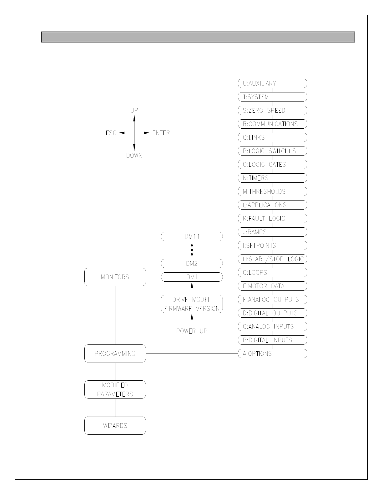
5.2 Menu Structure
When power is applied to the drive, the HMI displays the drive's firmware version. After a short
timeout, the Drive Monitor 1 (DM1) screen is displayed. Navigation through the menu is achieved by
using the Up, Down, Escape, and Enter keys.
Figure 10
15

Monitors
The Monitors section contain the Drive Monitor screens. Each of theses screens displays various
drive status information.
Monitor Description
DM01 Reference/Speed
DM02 Armature Status
DM03 Field Status
DM04 Fault Status
DM05 Alarm Status
DM06 Velocity Loop Status
DM07 Current Loop Status
DM08 Field Loop Status
DM09 Loop Outputs
DM10 Feedback Status
DM11 Drive Model/Firmware
Table 3: Drive Monitor Descriptions
Programming
The drive parameters are located under the Programming section. Each drive parameter has a
unique identifier tag that consists of an alpha group code, and numeric block code, and a two digit
numeric index. For example, parameter C2.04 is in Group C, Block 2, and Index 4. When the
programming section is first displayed, the first parameter (A1.01) is displayed with the Group Code
flashing (i.e. the 'A'). The Up/Down keys are then used to change the Group Code to the desired
value. Pressing the Reset/Right key will move the cursor to the right and cause the Block Code to
begin flashing. The Up/Down keys are then used to change the Block Code. Pressing the
Reset/Right key will move the cursor to the right and cause the Index Code to begin flashing. Again,
the Up/Down keys are used to change the Index to display the desired parameter. Pressing Escape
will move the cursor left.
In order to simplify the menu, some parameters are hidden when they are not applicable. However,
in some cases it may be desired to view these hidden parameters. There are two ways to view these
hidden parameters. The first method is to change parameter A1.01 from STANDARD to
ADVANCED. This makes all parameters visible. The second method is to use a certain keystroke
while scrolling through the parameters. Pressing the F2 key before pressing the Up or Down keys
will force the display to show the next/previous parameter (whether it is hidden or not).
Once a parameter is displayed, pressing the Enter key will allow its value to be modified. The current
value of the parameter (or a digit in its value) will begin flashing. The Up/Down keys are used to
adjust the value. If the parameter is a numeric value, the Reset/Right key can be used to shift the
cursor to the right to allow other digits to be adjusted. Pressing the Reset/Right key when the cursor
is on the last digit will cause the cursor to be placed on the first digit. Once the desired value is
displayed, the value can be entered by pressing the Enter key. The Escape key will exit the
parameter adjustment screen without changing the parameter value.
Note: When parameters are altered via the keypad, the changes are saved automatically.
Modified Parameters
This section contains a list of parameters that have been modified from the default factory preset
value. The Up/Down keys are used to scroll through the list.
Wizards
This section contains various drive related wizards that aid in drive setup.
16

6666
Start Up Procedure
6.1 Pretest
1. Verify each phase of the 3 phase power supply. Input voltage should be checked ahead
of the supplying circuit breaker, disconnect switch, etc. before it is switched on.
2. Connections should be visually inspected and checked for tightness. An ohmmeter can
be used to check for ground faults. Ground faults in un-isolated circuits of the armature
and field can cause fuse blowing and damage to the motor and control. To check for
grounds with an ohmmeter, select a high resistance scale such as R x 100K ohms or
greater. Test from each connection terminal (including shields) to chassis ground and be
suspicious of any resistance reading less than 500K ohms. NOTE: An exception to this
test would be made where the drive's 3 phase input is connected to a grounded "Y" type
transformer secondary.
3. Adjust external reference (Analog Input 1) at terminal 10 to 0 volts.
4. Apply single phase control power and three phase bridge power. On initial power up, the
drive should display an Invalid Motor Data fault. Press CLOSE to exit. When asked to
run the Basic Setup Wizard, select YES. If the wizard was cancelled, it can be re-started
6.2 Adjustment Procedure: Velocity (Speed) Regulator
from the Wizards section in the menu.
1. Presets
Use the Basic Setup Wizard to set the required parameters. The wizard will step you
through various drive parameters. When a parameter is displayed, press the ENT key
to edit its value. There are a number of required parameters. The wizard will not
allow you to proceed until a valid value has been entered. It is recommended that the
drive initially be setup using armature feedback even if a tachometer or encoder will
be used. This allows the proper feedback signal to be verified before using it for
control. After the motor data is entered in the wizard, the drive should begin
producing field output. Depending upon the wizard data entered, you may have the
option to operate the field in either open or closed loop mode. After the field mode is
selected, the wizard will display a field status screen showing the field voltage and
field current. Verify the displayed values correspond to the motor nameplate. In many
cases, when a motor is cold and the nameplate field voltage is applied, the field
current will be much higher than its rated nameplate value. As the motor warms up,
the field winding resistance should increase, which will cause the field current to
decrease. If open loop was selected and the field output requires additional
adjustment, press the ENT key while the status screen is displayed. This allows
adjustment of Open Loop Reference (G3.03). Regardless of the mode, please
ensure the field levels are correct before proceeding.
2. Clear any Faults
When the wizard is completed, the drive will try to clear any faults that are present. If
a fault is still present (i.e. the Fault LED is on or flashing), navigate to the DM04
screen to display the current fault. Once the fault condition is removed, the fault can
be cleared by pressing the RESET key while on any DM screen.
3. Validate E-STOP
When an E-STOP is activated, the status display on the DM01 screen should display
E-STOP. When the E-STOP is cleared, the status should display STOP or FAULT. If
E-STOP is always displayed, not all interlocks have been made. Please refer to the
wiring diagram in Figure 6 on page 12. The 24V from terminal 38 should flow through
all the interlocks to terminal 9. Do not proceed until the E-STOP functions properly.
4. Safety Check
During the following steps the motor will be rotated. If excessive speed or wrong
direction of rotation could damage the load, it may be wise to de-couple the load until
17

5. Check Motor Rotation
6. Validate External Start/Stop
7. Validate Reverse Direction (optional, EP4 regenerative unit required)
8. Validate Tachometer Feedback (required only if a motor mounted tachometer is used)
9. Validate Encoder Feedback (required only if a motor mounted encoder is used)
proper control is verified.
While displaying the DM01 screen, place the drive in local mode by pressing the
LOCAL/REMOTE key. The Local LED should be on. Press and hold the F1 key to
jog the drive. The armature contactor should close and the motor should rotate slowly.
Observe the direction of rotation. Release F1 to stop the drive. If the motor rotation is
reversed, remove all power and reverse the motor armature or field wires. If used,
observe proper polarization of the series field winding per the instructions in Section
4.2. After re-applying power, repeat this step to verify motor direction.
Press the LOCAL/REMOTE key to return the drive to Remote mode. The Local mode
LED should be off. Adjust the external reference signal connected to terminal 10 to its
minimum. Typically, the reference value on DM01 should be approximately zero.
Place the drive in Run mode via the external contacts. Slowly increase the external
reference until the motor is rotating. Issue a stop command using the external
contacts and verify the motor stops and the contactor de-energizes.
With reference at minimum, run the drive in the reverse direction. Slowly increase the
reference and verify motor runs in reverse direction. Stop drive.
Proper tachometer operation should be checked while the drive is running in Armature
Feedback. Place the drive in run mode and run at a low speed (approximately 20%).
On the display, navigate to DM10. Compare Armature feedback to Tachometer
feedback. The values should be approximately equal (within 5%). If the values have
approximately the same value but the wrong polarity, press the Stop button and invert
the tachometer feedback by setting parameter F2.02 to On. Place the drive back in
the run mode and re-check. If the values are not equal, verify the tachometer data is
entered properly in section F2 (or the wizard) and jumpers J1-J3 are set properly.
Once corrected and the values are equal at low speeds, increase speed and check at
higher speeds. If the values are approximately equal throughout the speed range, the
drive can be placed in the tachometer feedback. With the drive in the stop mode, set
parameter G2.15 to Tachometer. Run drive and verify proper operation.
Proper encoder operation should be checked while the drive is running in Armature
Feedback. Place the drive in run mode and run at a low speed (approximately 20%).
On the display, navigate to DM10. Compare Armature feedback to Encoder feedback.
The values should be approximately equal (within 5%). If the values have
approximately the same value but the wrong polarity, press the Stop button and invert
the encoder feedback by setting parameter F3.03 to On. Place the drive back in the
run mode and re-check. If the values are not equal, verify the encoder data is entered
properly in section F2 (or the wizard). Once corrected and the values are equal at low
speeds, increase speed and check at higher speeds. If the values are approximately
equal throughout the speed range, the drive can be placed in the encoder feedback.
With the drive in the stop mode, set parameter G2.15 to Encoder. Run drive and verify
proper operation.
18

6.3 Adjustment Procedure: Constant Horsepower
1. Presets
Set up the Elite Pro V3 drive as a normal velocity regulator to run at the motor's base
speed using tachometer or encoder feedback with closed loop field control. Refer to
Section 6.2 above. Once correct operation in this mode has been achieved, proceed
2. Parameters
3. Test
with the following steps.
Re-run the Basic Setup Wizard and set the Operating Mode to CONST HP
(CROSSOVER). Continue through the wizard and enter additional motor data
(specifically the extended speed field amps, and extended speed value). If
tachometer is used, re-scale Jumpers J1-J3 as instructed by the wizard.
With reference at minimum, place drive in run mode. Navigate to DM03 and verify the
motor field current is at the base speed level. Navigate to DM02 to display the
armature voltage. Slowly increase reference until armature voltage is approximately
85% of the nameplate value (204V for 240V armatures, or 425V for 500V armatures).
Return to DM03 and monitor the motor field current, while increasing the speed
reference. The field current should begin decreasing as the speed reference is
increased. When the maximum reference is applied, the field current should be
approximately at the extended speed field current level. Return to DM02 and verify
armature voltage is at the motor's rated armature voltage level.
6.4 Adjustment Procedure: Torque (Current) Regulator
1. Presets
Set up the Elite Pro V3 drive as a normal velocity regulator to run at the motor's base
speed using armature feedback. Refer to Section 6.2. Once correct operation in this
2. Parameters
3. Test
mode has been achieved, proceed with the following steps.
Re-run the Basic Setup Wizard and set the Operating Mode to TORQUE. Continue
through the wizard and enter any required data.
With reference at minimum, place drive in run mode. Navigate to DM02 to display the
armature current. Slowly increase reference and verify control of armature current.
6.5 Calibration & Fine Tuning
1. If the drive is using armature feedback (i.e. G2.15 is set to ARMATURE), then IR
Compensation (G2.09) can be adjusted to improve the speed regulation with load
changes. Adjustment is best done when the motor or machine can be loaded normally. If
the motor is normally operated at a particular speed, adjust IR Compensation (G2.09)
while running at that speed. If the motor operates under load over a wide speed range,
pick a speed near mid-range to make the adjustment. Adjust as follows:
Operate the unloaded motor at the normal or mid-range speed and note the exact
speed using a hand tachometer or other speed measuring device. While still
monitoring speed, apply normal load. The reduction in speed of a fully loaded motor
will usually fall between 2 and 13% of rated or "base" speed. Slowly increase IR
Compensation (G2.09) until the loaded speed equals the unloaded speed measured
in the previous step. Making this adjustment may now cause the unloaded speed to
be slightly higher. Repeat this procedure until there is no difference between loaded
and unloaded speed levels. Use care not to set the adjustment too high or speed
increase with load and instability may result. NOTE: For this adjustment, do not use
armature voltage feedback (AFB) to measure speed. Armature voltage is not an exact
indication of loaded motor speed!
19
2. The Current Proportional Gain (G1.16), Current Integral Time (G1.17), Velocity
Proportional Gain (G2.21), and Velocity Integral Time (G2.22) parameters are preset
by Carotron to provide stable and responsive performance under most load conditions.
When required, the drive performance can be optimized for a particular application or to
correct undesirable operation by use of these adjustments. The adjustments are complex
though and can adversely affect operation if not properly set. In general, the settings that
give the most stable operation do not always give the fastest response.
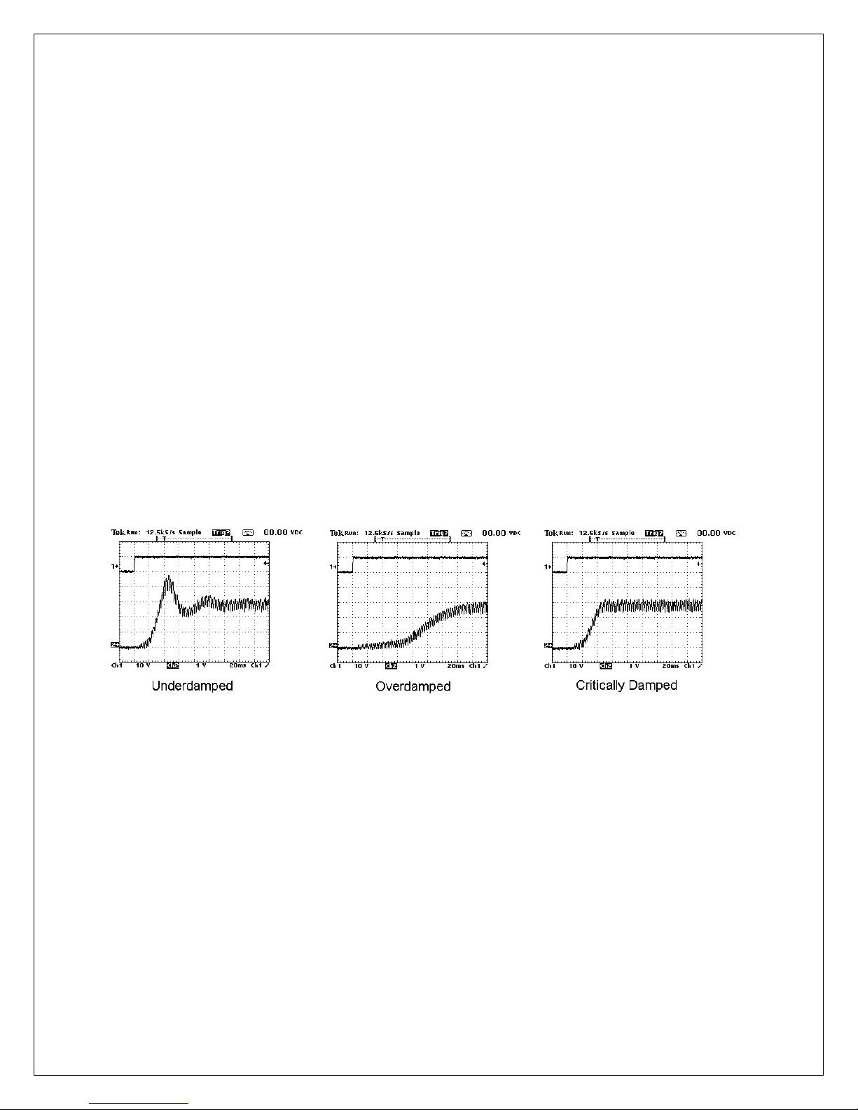
Current Loop
The current loop can be manually tuned by directly applying a stepped reference and
monitoring the current feedback. In order to adjust properly, connect an oscilloscope
between common and the A.IFB testpoint on the control board. The rotor shaft must not
rotate during this procedure. Therefore, set Field Enable (G3.01) to DISABLE to remove
voltage from the shunt field. Set Reference Select (G1.01) to STEP. Set the Step
Reference (G1.22) initially to a low value (around 20%). Set the Step Duration (G1.23) to
500ms. Place the drive in the run mode. Set Step Enable (G1.24) to ENABLE to apply a
step change to the PI loop. The current feedback signal should respond quickly with
minimum overshoot. Adjust the Current Proportional Gain (G1.16) and Current Integral
Time (G1.17) parameters and re-apply the Step Enable until a critically damped waveform
as seen in Figure 11. Increasing the proportional gain improves the response but
increases the overshoot. Reducing the integral time improves the response but can cause
instability if set too low. Once a critically damped waveform is obtained, increase the Step
Reference to 40% and repeat above. Continue until a Step Reference of 100% is
achieved. Return Field Enable (G3.01) to ENABLE and Reference Select (G1.01) to
NORMAL when complete.
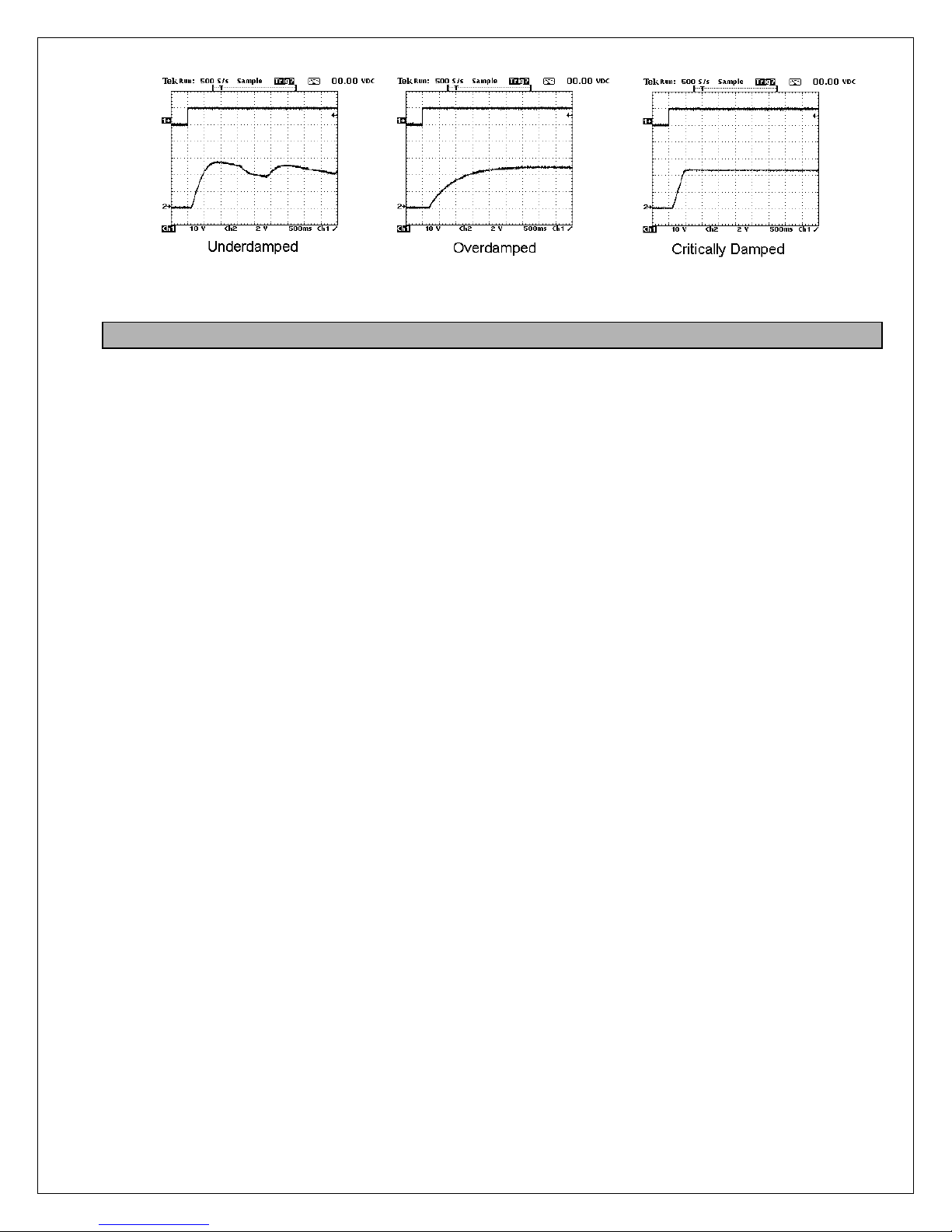
Velocity Loop
In order to adjust properly, connect an oscilloscope to Analog Output 1 Terminal 21
(Velocity Feedback). Using the HMI, temporarily set the Reference Select (G2.29) to
STEP. Set Step Reference (G2.30) to 20% and Step Duration (G2.31) initially to 2
seconds. Place the drive in the run mode and apply a step change by setting Step Enable
(G2.32) to ENABLE. Observe the response of the drive on the oscilloscope. The motor
speed should respond quickly with minimum overshoot. Adjust the Velocity Proportional
Gain (201) and Velocity Integral Time (202) parameters to obtain a critically damped
waveform as seen in Figure 12. Increasing the proportional gain improves the response
but increases the overshoot. Reducing the integral time improves the response but can
cause instability if set too low. Repeat above in steps gradually increasing the Step
Reference to 100% (or the max required speed is obtained). Once complete, return
Reference Select (G2.29) to NORMAL.
20
Figure 11
6.4 Password Protection
If password protection is required, set the appropriate password under A1.04. Please note
that this is a special hidden parameter. You must first display A1.03. Then press F2 key and
then the Up key to display A1.04. Once A1.04 has a value other than zero, parameters can
be viewed but cannot be changed. Changes can only be made by first entering the password
into parameter A1.05. Once all changes have been made, A1.05 can be manually returned
to 0 to logout. The drive also has a timeout feature, that automatically clears the entered
password in A1.05 after 5 minutes.
Figure 12
21
7777
Programming & Adjustments
Programming and adjustment of the Elite Pro is accomplished by
changing parameter settings. Each parameter has a Tag identifier
and a descriptive name. Parameters are separated into groups
and blocks according to their function. The following sections
contain each software block diagram and descriptions of each
parameter function. Refer to Figure 13 for key conventions that are
used in the block diagrams. Each parameter is one of three types:
Read-Write (RW), Inhibit Change while Running (ICR), or ReadOnly (RO). ICR parameters can be changed only when the drive is
not running.
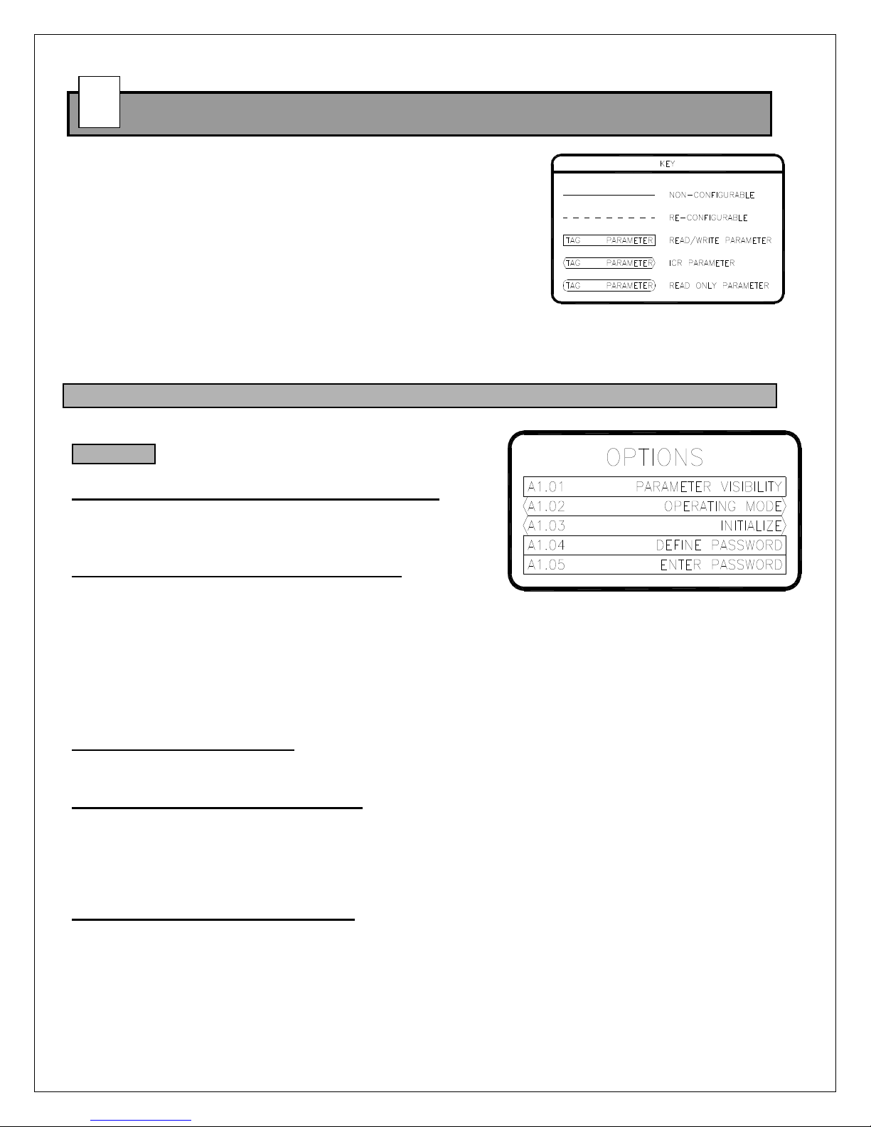
7.1 A: Options
These parameters set the drive's basic operating mode.
A1: Options
A1.01 Parameter Visibility (R/W, Preset: Standard)
When set to Standard, parameters that are typically not
relevant to the current operating mode are hidden.
When set to Advanced, all parameters are visible.
A1.02 Operating Mode (ICR, Preset: Velocity)
Sets the drive's operating mode.
VELOCITY
A1.03 Initialize (ICR, Preset: 0)
9999: Re-initializes the drive and returns all parameters to the factory default setting.
Range: 0..65535
A1.04 Define Password (R/W, Preset: 0)
A numeric password may be set to prevent unauthorized parameter changes. After a numeric
password has been entered, the drive allows all parameters to be viewed, but prevents changes
from being made. Only after a valid password has been entered into A1.05 can changes be
made. This parameter requires a special keystroke to display. With A1.03 displayed, press F2
and then UP. Range: 0..65535
A1.05 Enter Password (R/W, Preset: 0)
If a numeric password has been defined in parameter A1.04, the same password must be
entered into parameter A1.05 before any parameter changes can be made. As a security
feature, the drive automatically clears the entered password after 5 minutes. Parameter A1.05 is
typically only visible after a password is defined in parameter A1.04. Range: 0..65535
Drive regulates motor speed.
CONST HP (CROSOVER)
Drives regulates speed utilizing the motor's extended speed range. Also known as field
weakening or field crossover.
TORQUE
Drive regulates motor torque (or armature current).
Figure 13
Figure 14
22
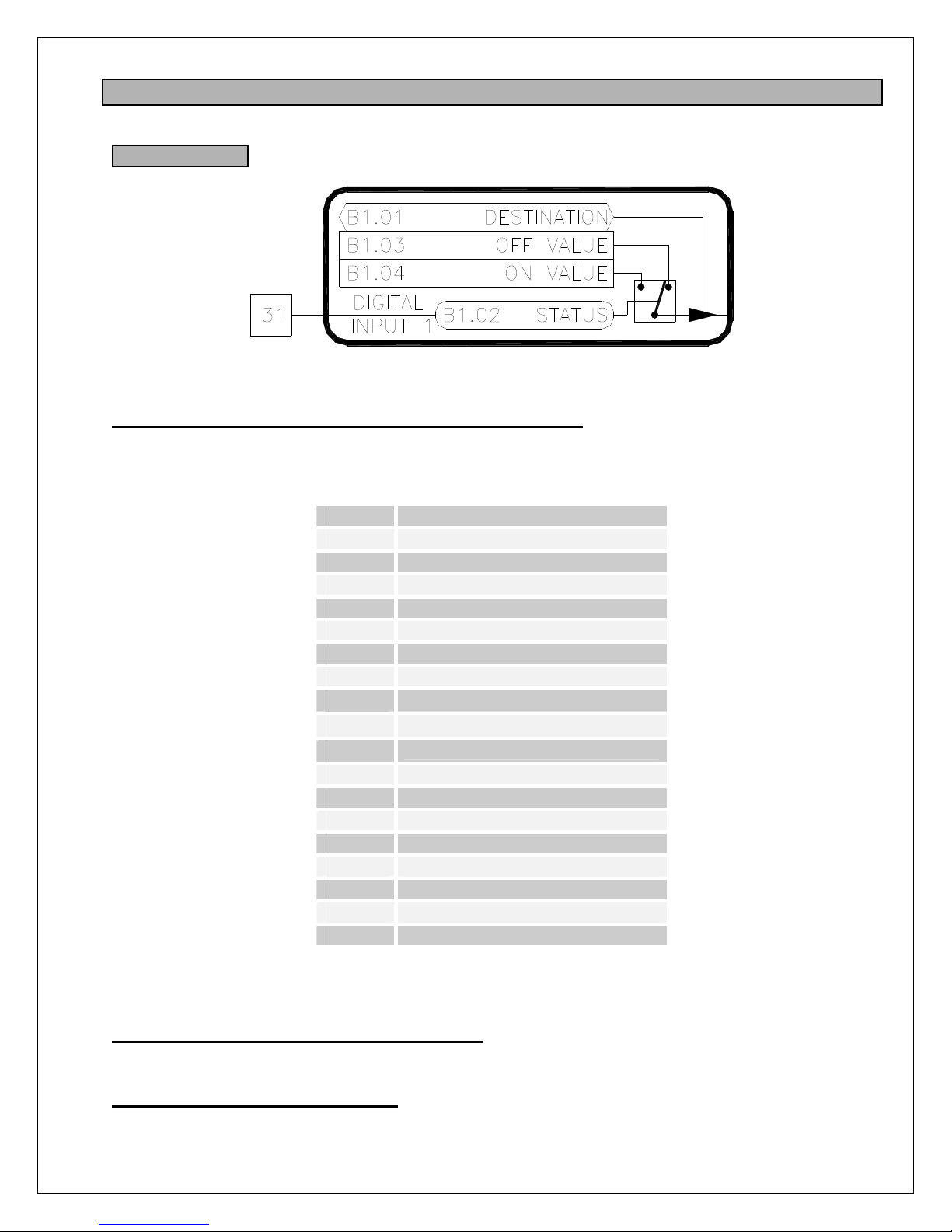
7.2 B: Digital Inputs
These parameters configure the drive's physical digital inputs (digital & frequency).
B1: Digital Input 1
B1.01 Digital Input 1 Destination (ICR, Preset: H1.02 [Run])
Determines the function of the digital input. Each digital input can control (or write to) any R/W
parameter in the drive. The destination parameter contains the tag of the parameter the input will
control (i.e. the target parameter). Refer to Table 4 for a list of commonly used functions.
Value Function
H1.02 Start-Run-Run Fwd*
H1.03 /Stop-Run Rev*
H1.04 Jog-Jog Fwd*
H1.05 Rev-Jog Rev*
H1.08 /Coast Stop
H1.09 /Quick Stop
H1.10 /Dynamic Brake Stop
I
1.01
I
1.02
I
1.03
J1.18 Ramp 1 Bypass
K1.14 External Fault
K1.15 Fault Reset
L1.01 PID Enable
L1.02 PID Reset
L6.01 MOP Increase
L6.02 MOP Decrease
L6.07 MOP Reset
Table 4: Common Digital Input Functions
*The actual function is determined by the H1.01 setting.
B1.02 Digital Input 1 Status [Terminal 31] (RO)
Displays the status of the digital input. A value of OFF indicates the digital input is off or not
activated. A value of ON indicates the digital input is on or active.
B1.03 Digital Input 1 Off Value (RW)
This is the value written to the target parameter when the digital input's status is OFF. The limits
and units of these parameters will change to match the limits and units of the target parameter.
Figure 15
Aux Reference Enable
Ref Select (MSB)
Ref Select (LSB)
23
B1.04 Digital Input 1 On Value (RW)
This is the value written to the target parameter when the digital input's status is ON. The limits
and units of these parameters will change to match the limits and units of the target parameter.
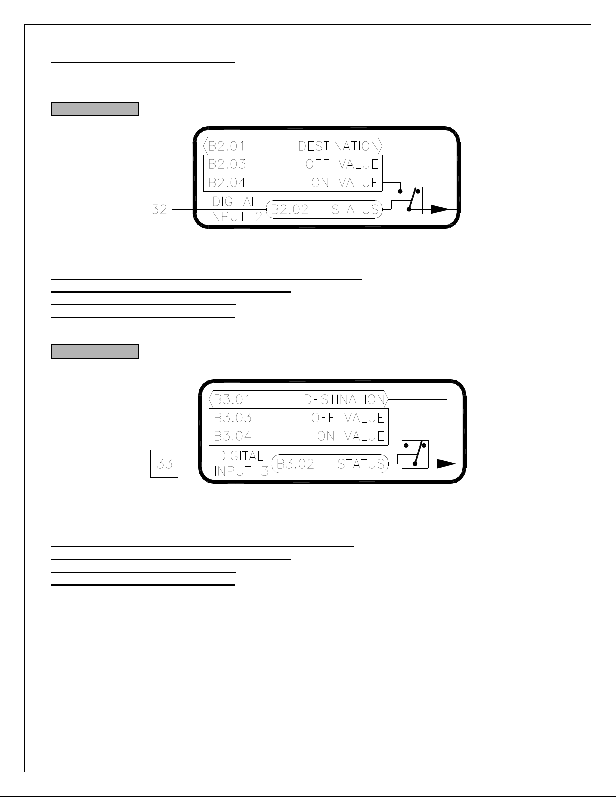
B2: Digital Input 2
B2.01 Digital Input 2 Destination (ICR, Preset: H1.03 [/Stop])
B2.02 Digital Input 2 Status [Terminal 32] (RO)
B2.03 Digital Input 2 Off Value (RW)
B2.04 Digital Input 2 On Value (RW)
Digital Input 2 is functionally equivalent to Digital Input 1. Refer to B1.XX
B3: Digital Input 3
B3.01 Digital Input 3 Destination (ICR, Preset: H1.04 [Jog])
B3.02 Digital Input 3 Status [Terminal 33] (RO)
B3.03 Digital Input 3 Off Value (RW)
B3.04 Digital Input 3 On Value (RW)
Digital Input 3 is functionally equivalent to Digital Input 1. Refer to B1.XX
Figure 16
Figure 17
24
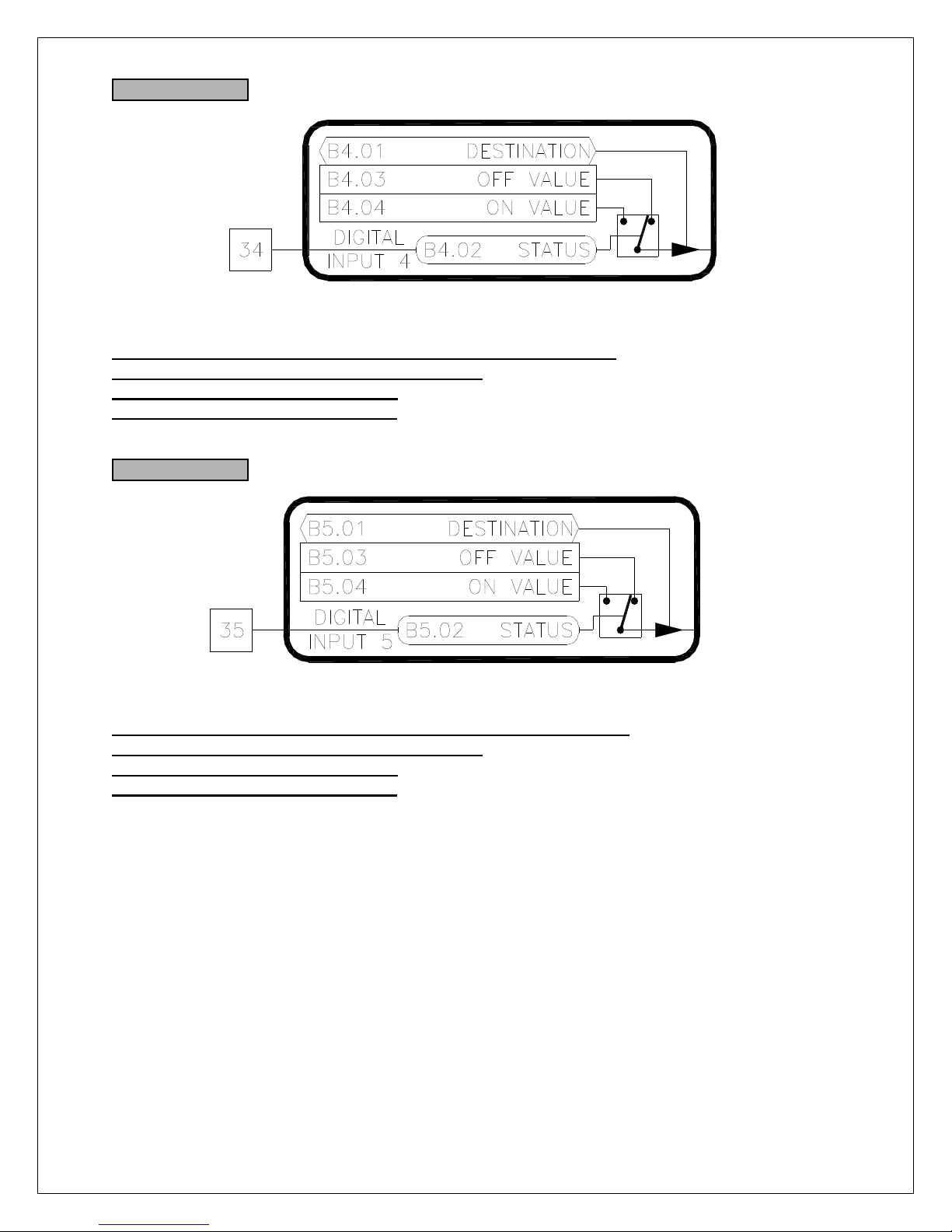
B4: Digital Input 4
B4.01 Digital Input 4 Destination (ICR, Preset: H1.05 [Reverse])
B4.02 Digital Input 4 Status [Terminal 34] (RO)
B4.03 Digital Input 4 Off Value (RW)
B4.04 Digital Input 4 On Value (RW)
Digital Input 4 is functionally equivalent to Digital Input 1. Refer to B1.XX
B5: Digital Input 5
B5.01 Digital Input 5 Destination (ICR, Preset: I1.02 [RefSelMsb])
B5.02 Digital Input 5 Status [Terminal 35] (RO)
B5.03 Digital Input 5 Off Value (RW)
B5.04 Digital Input 5 On Value (RW)
Digital Input 5 is functionally equivalent to Digital Input 1. Refer to B1.XX
Figure 18
Figure 19
25
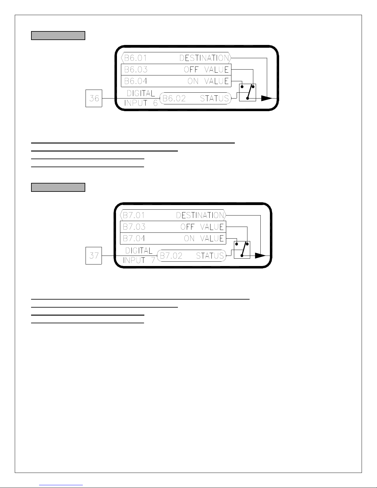
B6: Digital Input 6
B6.01 Digital Input 6 Destination (ICR, Preset: I1.03 [RefSelLsb])
B6.02 Digital Input 6 Status [Terminal 36] (RO)
B6.03 Digital Input 6 Off Value (RW)
B6.04 Digital Input 6 On Value (RW)
Digital Input 6 is functionally equivalent to Digital Input 1. Refer to B1.XX
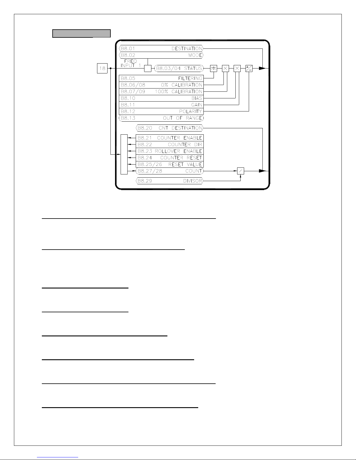
B7: Digital Input 7
B7.01 Digital Input 7 Destination (ICR, Preset: K1.15 [ExtFaultReset])
B7.02 Digital Input 7 Status [Terminal 37] (RO)
B7.03 Digital Input 7 Off Value (RW)
B7.04 Digital Input 7 On Value (RW)
Digital Input 7 is functionally equivalent to Digital Input 1. Refer to B1.XX
Figure 20
Figure 21
26
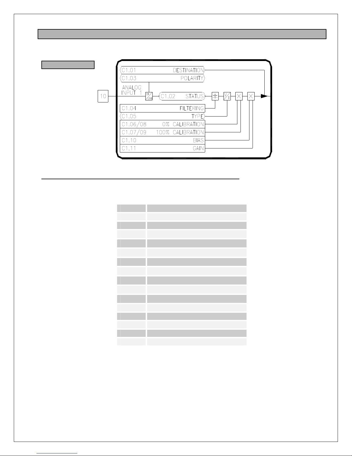
B8: Frequency Input
B8.01 Freq Input Destination (ICR, Preset: 00.00 [Not Set])
The frequency input can control (or write to) any R/W parameter in the drive. The destination
parameter contains the tag of the parameter the input will control (i.e. the target parameter).
Refer to Table 5 on page 29 for a list of commonly used functions.
B8.02 Freq Input Mode (ICR, Preset: Freq Input)
The frequency input can operate in either the FREQ INPUT or SONIC INPUT modes. In the
frequency input mode, the input level is determined by the input frequency. The sonic mode is
used in conjunction with Carotron's sonic transducer (P/N: C10757-000 or C11307-000) to
measure distance.
B8.03 Freq Input Status (RO)
Valid only when B8.02 equals FREQ INPUT. Displays the frequency input level at terminal 18 in
Hertz.
B8.04 Freq Input Status (RO)
Valid only when B8.02 equals SONIC INPUT. Displays the measured distance of the sonic
transducer connected to terminal 18 in inches.
B8.05 Freq Input Filtering (R/W, Preset: 0)
Sets the level of digital filtering applied to the input signal. The adjustment ranges from 0 (no
filtering) to 15 (heavily filtered).
B8.06 Freq Input 0% Calibration (R/W, Preset: 0Hz)
Defines the minimum input frequency in Hertz. An input value below this level will be ignored.
This parameter is only used when in the FREQ INPUT mode. Range: 0..50,000Hz
B8.07 Freq Input 100% Calibration (R/W, Preset: 50000Hz)
Defines the maximum input frequency in Hertz. An input value above this level will be ignored.
This parameter is only used when in the FREQ INPUT mode. Range: 0..50,000Hz
B8.08 Freq Input 0% Calibration (R/W, Preset: 6.00")
Defines the minimum input distance in inches. An input value below this level will be ignored.
This parameter is only used when in the SONIC INPUT mode. Range: 0..420"
Figure 22
27

B8.09 Freq Input 100% Calibration (R/W, Preset: 420.00")
Defines the maximum input distance in inches. An input value above this level will be ignored.
This parameter is only used when in the SONIC INPUT mode. Range: 0..420"
B8.10 Freq Input Bias (R/W, Preset: 0.00)
Defines the value of the target parameter when the input signal is less than or equal to the 0%
Calibration. Note that the formatting of this parameter will change to match that of the target
parameter. For example, if the target parameter is in percent, this parameter will be in percent. If
the target parameter is True/False, this parameter will be True/False.
B8.11 Freq Input Gain (R/W, Preset: 100.00)
Defines the value of the target parameter when the input signal is greater than or equal to the
100% Calibration. Note that the formatting of this parameter will change to match that of the
target parameter.
B8.12 Freq Input Polarity (R/W, Preset: Positive)
Defines the polarity of the target parameter. When set to POSITIVE, the target parameter will
have a positive value. Likewise, when set to NEGATIVE, the target parameter will be negative.
B8.13 Out of Range (RO)
Displays the status of the sonic transducer distance measurement. If B8.04 is 10% less than
B8.08 or B8.04 is 10% greater than B8.09, this parameter will be TRUE indicating the target is
out of range.
B8.20 Counter Destination (ICR, Preset: 00.00 [Not Set])
The drive has a counter associated with the frequency input. This count value can control (or
write to) any R/W parameter in the drive. The destination parameter contains the tag of the
parameter the input will control (i.e. the target parameter).
B8.21 Counter Enable (R/W, Preset: Disabled)
The counter is enabled when set to ENABLED.
B8.22 Counter Direction (R/W, Preset: Up)
Controls the direction of the counter. When set to UP, each pulse on the input will cause the
counter (B8.26/27) to increase. When set to DOWN, each pulse on the input will cause the
counter to decrease.
B8.23 Rollover Enable (R/W, Preset: Disabled)
When ENABLED, the counter is allowed to rollover from maximum to minimum when counting
up, or to rollover from minimum to maximum when counting down. If DISABLED, rollover is not
allowed and the count value will stop and hold its value at the maximum or minimum.
B8.24 Counter Reset (R/W, Preset: Off)
Resets the counter (B8.26/27) to the Reset Value (B8.24/25) when ON.
B8.25 Reset Value Lo (R/W, Preset: 0)
B8.26 Reset Value Hi (R/W, Preset: 0)
The 32 bit counter will be preset to the value in these two registers when B8.23 is ON.
B8.27 Counter Lo (RO)
B8.28 Counter Hi (RO)
The 32 bit counter is split into two 16 bit sections (B8.28:B8.27). The counter has a maximum
value of 4,294,967,295.
B8.29 Divisor (ICR, Preset: 1)
The 32 bit count value is divided by this value before being written to the target parameter.
Range: 0..65535
28
7.3 C: Analog Inputs
These parameters configure the drive's physical analog inputs.
C1: Analog Input 1
C1.01 Analog Input 1 Destination (ICR, Preset: I1.04 [Reference A])
Each of the analog inputs can control (or write to) any R/W parameter in the drive. The
destination parameter contains the tag of the parameter the input will control (i.e. the target
parameter). Refer to Table 5 for a list of commonly used functions.
Value Function
G1.05 POSITIVE CURRENT LIMIT
G1.06 NEGATIVE CURRENT LIMIT
I
1.04
I1
.05
I
1.06
I
1.07
I
1.08
I
2.02
I
2.04
I
2.06
L1.13 AUX PID SETPOINT
L1.14 AUX PID FEEDBACK
L1.23 AUX PID SCALE
L2.07 DIA CALC: EXT DIA RATIO
L4.01 TENSION CALC: TENSION SET
Table 5: Common Analog & Freq Input Functions
Figure 23
REF A
REF B
REF C
REF D
JOG REF
SETPOINT B
SETPOINT C
SETPOINT D
29
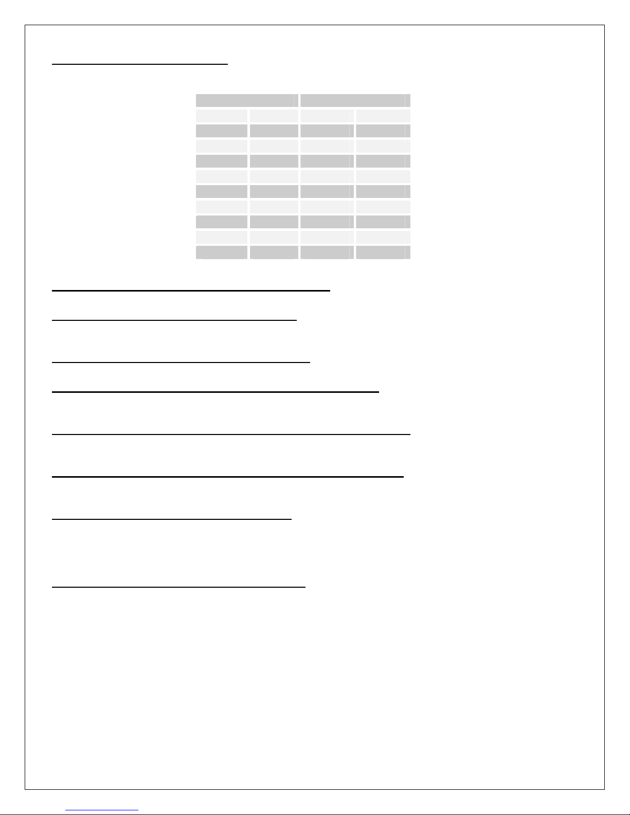
C1.02 Analog Input 1 Status (RO)
Displays the raw analog to digital conversion value. Table 6 below lists the typical status values
for common input levels.
C1.03 Analog Input 1 Polarity (ICR, Preset: Unipolar)
Configures the type of analog input signal used, either UNIPOLAR or BIPOLAR.
C1.04 Analog Input 1 Filtering (R/W, Preset: 0)
Sets the level of digital filtering applied to the input signal. The adjustment ranges from 0 (no
filtering) to 15 (heavily filtered). Range: 0..15
C1.05 Analog Input 1 Type (ICR, Preset: Voltage)
Configures the type of analog input signal used, either VOLTAGE or CURRENT.
C1.06 Analog Input 1 Unipolar 0% Calibration (R/W, Preset: 0)
Defines the minimum signal level in UNIPOLAR mode. An input value below this level will be
ignored. Refer to Figure 24. Range: 0..4095
C1.07 Analog Input 1 Unipolar 100% Calibration (R/W, Preset: 4095)
Defines the maximum raw signal level in UNIPOLAR mode. An input value above this level will
be ignored. Refer to Figure 24. Range: 0..4095
C1.09 Analog Input 1 Bipolar 100% Calibration (R/W, Preset: 2047)
Defines the maximum raw positive and negative signal levels in BIPOLAR mode. Any input
value exceeding this level will be ignored. Refer to Figure 24. Range: 0..2047
C1.10 Analog Input 1 Bias (R/W, Preset: 0.00)
Defines the value of the target parameter when the input signal is less than or equal to the 0%
Calibration. Refer to Figure 24. Note that the formatting of this parameter will change to match
that of the target parameter. For example, if the target parameter is percent, this parameter will
be percent. If the target parameter is Seconds, this parameter will be Seconds.
C1.11 Analog Input 1 Gain (R/W, Preset: 100.00)
Defines the value of the target parameter when the input signal is greater than or equal to the
100% Calibration. Refer to Figure 24. Note that the formatting of this parameter will change to
match that of the target parameter.
Signal Input Status
Voltage Current Unipolar Bipolar
+10V - 4095 2047
+7.5V - 3070 1535
+5V 20mA 2047 1023
+2.5V 10mA 1023 511
0V 0mA 0 0
-2.5V -10mA - -512
-5V -20mA - -1024
-7.5V - - -1536
-10V - - -2048
Table 6: Analog Input Status Readings
30

C2: Analog Input 2
C2.01 Analog Input 2 Destination (ICR, Preset: 00.00 [Not Set])
C2.02 Analog Input 2 Status (RO)
C2.03 Analog Input 2 Polarity (ICR, Preset: Unipolar)
C2.04 Analog Input 2 Filtering (R/W, Preset: 0)
C2.05 Analog Input 2 Type (ICR, Preset: Voltage)
C2.06 Analog Input 2 0% Calibration (R/W, Preset: 0)
C2.07 Analog Input 2 100% Calibration (R/W, Preset: 4095)
C2.08 Analog Input 2 0% Calibration (R/W, Preset: 0)
C2.09 Analog Input 2 100% Calibration (R/W, Preset: 2047)
C2.10 Analog Input 2 Bias (R/W, Preset: 0.00)
C2.11 Analog Input 2 Gain (R/W, Preset: 100.00)
Analog Input 2 is functionally equivalent to Analog Input 1. Refer to C1.XX.
Figure 24
Figure 25
31

C3: Analog Input 3
C3.01 Analog Input 3 Destination (ICR, Preset: 00.00 [Not Set])
C3.02 Analog Input 3 Status (RO)
C3.03 Analog Input 3 Polarity (ICR, Preset: Unipolar)
C3.04 Analog Input 3 Filtering (R/W, Preset: 0)
C3.05 Analog Input 3 Type (ICR, Preset: Voltage)
C3.06 Analog Input 3 0% Calibration (R/W, Preset: 0)
C3.07 Analog Input 3 100% Calibration (R/W, Preset: 4095)
C3.08 Analog Input 3 0% Calibration (R/W, Preset: 0)
C3.09 Analog Input 3 100% Calibration (R/W, Preset: 2047)
C3.10 Analog Input 3 Bias (R/W, Preset: 0.00)
C3.11 Analog Input 3 Gain (R/W, Preset: 100.00)
Analog Input 3 is functionally equivalent to Analog Input 1. Refer to C1.XX.
C4: Analog Input 4
C4.01 Analog Input 4 Destination (ICR, Preset: 00.00 [Not Set])
C4.02 Analog Input 4 Status (RO)
C4.03 Analog Input 4 Polarity (ICR, Preset: Unipolar)
C4.04 Analog Input 4 Filtering (R/W, Preset: 0)
C4.05 Analog Input 4 Type (ICR, Preset: Voltage)
C4.06 Analog Input 4 0% Calibration (R/W, Preset: 0)
C4.07 Analog Input 4 100% Calibration (R/W, Preset: 4095)
C4.08 Analog Input 4 0% Calibration (R/W, Preset: 0)
C4.09 Analog Input 4 100% Calibration (R/W, Preset: 2047)
C4.10 Analog Input 4 Bias (R/W, Preset: 0.00)
C4.11 Analog Input 4 Gain (R/W, Preset: 100.00)
Analog Input 4 is functionally equivalent to Analog Input 1. Refer to C1.XX.
Figure 26
Figure 27
32

C5: Analog Input 5
C5.01 Analog Input 5 Destination (ICR, Preset: 00.00 [Not Set])
C5.02 Analog Input 5 Status (RO)
C5.03 Analog Input 5 Polarity (ICR, Preset: Unipolar)
C5.04 Analog Input 5 Filtering (R/W, Preset: 0)
C5.05 Analog Input 5 Type (ICR, Preset: Voltage)
C5.06 Analog Input 5 0% Calibration (R/W, Preset: 0)
C5.07 Analog Input 5 100% Calibration (R/W, Preset: 4095)
C5.08 Analog Input 5 0% Calibration (R/W, Preset: 0)
C5.09 Analog Input 5 100% Calibration (R/W, Preset: 2047)
C5.10 Analog Input 5 Bias (R/W, Preset: 0.00)
C5.11 Analog Input 5 Gain (R/W, Preset: 100.00)
Analog Input 5 is functionally equivalent to Analog Input 1. Refer to C1.XX.
Figure 28
33

7.4 D: Digital Outputs
These parameters configure the drive's physical digital outputs (relay & frequency/digital).
D1: Relay Output 1
D1.01 Relay Output 1 Source (ICR, Preset: S1.06 [Zero Speed])
The function of the relay output is configured by this parameter. Each output can be controlled
by any parameter in the drive. The source parameter contains the tag of the parameter that will
control the relay output. The source parameter's value is compared to the On Value and Off
Value parameters (Dx.03 & Dx.04) to determine if the relay is energized or de-energized. Refer to
Table 7 for a list of commonly used functions.
Value Function
G3.05 IN FIELD ECONOMY
H1.13 DRIVE IN RUN MODE
H1.14 DRIVE IN JOG MODE
H1.16 DRIVE RUNNING (RUN or JOG)
J1.22 DRIVE RAMPING
K2.08 DRIVE FAULT
K2.10 DRIVE READY
S1.06 AT ZERO SPEED
S1.07 AT STANDSTILL
D1.02 Relay Output 1 Absolute Value (R/W, Preset: Off)
When TRUE, the absolute value of the source parameter's value is taken before it is compared to
the Dx.03 and Dx.04.
D1.03 Relay Output 1 On Value (R/W, Preset: On)
The relay will energize (turn on) when the source parameter's value is greater than or equal to
this value. The limits and units of this parameter will change to match the limits and units of the
source parameter.
D1.04 Relay Output 1 Off Value (R/W, Preset: Off)
The relay will de-energize (turn off) when the source parameter's value is less than or equal to
this value. The limits and units of this parameter will change to match the limits and units of the
source parameter.
D1.05 Relay Output 1 Status (RO)
Displays the status of the relay output.
Table 7: Common Relay & Digital Output Functions
Figure 29
34

D2: Relay Output 2
D2.01 Relay Output 2 Source (ICR, Preset: H1.16 [Drive Running])
D2.02 Relay Output 2 Absolute Value (R/W, Preset: Off)
D2.03 Relay Output 2 On Value (R/W, Preset: On)
D2.04 Relay Output 2 Off Value (R/W, Preset: Off)
D2.05 Relay Output 2 Status (RO)
Relay Output 2 is functionally equivalent to Relay Output 1. Refer to D1.XX
D3: Relay Output 3
D3.01 Relay Output 3 Source (ICR, Preset: K2.08 [Drive Faulted])
D3.02 Relay Output 3 Absolute Value (R/W, Preset: Off)
D3.03 Relay Output 3 On Value (R/W, Preset: No)
D3.04 Relay Output 3 Off Value (R/W, Preset: Yes)
D3.05 Relay Output 3 Status (RO)
Relay Output 2 is functionally equivalent to Relay Output 1. Refer to D1.XX
Figure 30
Figure 31
35

D4: Frequency/Digital Output
D4.01 Freq/Digital Output Source (ICR, Preset: 00.00 [Not Set])
The function of this output is configured by this parameter. The output can be controlled by any
parameter in the drive. The source parameter contains the tag of the parameter that will control
the relay output. Refer to Table 7 for a list of commonly used functions when used as a digital
output. Refer to Table 8 for a list of commonly used functions when used as a frequency output.
D4.02 Freq/Digital Output Mode (ICR, Preset: Freq Out)
This open collector output can function in either a frequency or digital mode. In FREQ OUT
mode, the output is a pulse train. The frequency level of the output is based on the source
parameter's value. In DIGITAL OUT mode, the output is level is driven either on or off (similar to
a relay output).
D4.03 Freq Output Gain (R/W, Preset: 100.00%)
Used only in the FREQ OUT mode. This adjustment is used to scale the output level of the pulse
train. A gain of 100% with a source parameter value of 100% will yield maximum output
frequency (10kHz). Range: 0..300%
D4.04 Freq Output Bias (R/W, Preset: 0.00%)
Used only in the FREQ OUT mode. This adjustment is used to set a minimum frequency output
level. The percentage adjustment is based on the maximum frequency output level (10kHz).
Range: 0..300%
D4.05 Freq Output Status (RO)
Used only in the FREQ OUT mode. Displays the frequency output level.
D4.06 Digital Output Absolute Value (R/W, Preset: Off)
Used only in the DIG OUT mode. When TRUE, the absolute value of the source parameter's
value is taken before it is compared to the D4.07 and D4.08.
D4.07 Digital Output On Threshold (R/W, Preset: 0.01)
Used only in the DIG OUT mode. The output will turn on (sink current) when the source
parameter's value is greater than or equal to this value. The limits and units of this parameter will
change to match the limits and units of the source parameter.
D4.08 Digital Output Off Threshold (R/W, Preset: 0.00)
Used only in the DIG OUT mode. The output will turn off when the source parameter's value is
less than or equal to this value. The limits and units of this parameter will change to match the
limits and units of the source parameter.
D4.09 Digital Output Status (RO)
Used only in the DIG OUT mode. Displays the status of the digital output, either ON or OFF
Figure 32
36

D5: Aux LED Output
D5.01 Aux LED Source (ICR, Preset: H1.16 [Arm Pilot Status])
The function of this output is configured by this parameter. The output can be controlled by any
parameter in the drive. The source parameter contains the tag of the parameter that will control
the relay output. Refer to Table 7 for a list of commonly used functions.
D5.02 Aux LED Absolute Value (R/W, Preset: Off)
When TRUE, the absolute value of the source parameter's value is taken before it is compared to
the D5.03 and D5.04.
D5.03 Aux LED On Value (R/W, Preset: On)
The LED will turn on when the source parameter's value is greater than or equal to this value.
The limits and units of this parameter will change to match the limits and units of the source
parameter.
D5.04 Aux LED Off Value (R/W, Preset: Off)
The LED will turn off when the source parameter's value is less than or equal to this value. The
limits and units of this parameter will change to match the limits and units of the source
parameter.
D5.05 Aux LED Output Status (RO)
Displays the status of the LED output.
Figure 33
37

7.5 E: Analog Outputs
These parameters configure the drive's physical analog outputs.
E1: Analog Output 1
E1.01 Analog Output 1 Source (ICR, Preset: G2.18 [Filtered Velocity Feedback])
The function of this output is configured by this parameter. The output can be controlled by any
parameter in the drive. The source parameter contains the tag of the parameter that will control
the analog output level. Refer to Table 8 for a list of commonly used functions.
Value Function
G1.13 MOTOR ARM CURRENT
G2.07 MOTOR ARM VOLTAGE
G2.18 MOTOR SPEED
G3.09 MOTOR FIELD CURRENT
G3.13 MOTOR FIELD VOLTAGE
I
1.10
J1.21 RAMP OUTPUT
L1.25 AUX PID OUTPUT
Table 8: Common Analog & Freq Output Functions
E1.02 Analog Output 1 Gain (R/W, Preset: 100.00%)
This adjustment is used to scale the output level. A gain of 100% with a source parameter value
of 100% will yield maximum output level of 10V. Range: -300..300%
E1.03 Analog Output 1 Bias (R/W, Preset: 0.00%)
This adjustment is used to set a minimum output level. The percentage adjustment is based on
the maximum output level (10V). Range: -300..300%
E1.04 Analog Output 1 Absolute Value (R/W, Preset: Off)
When TRUE, the absolute value is taken after the Bias and Gain have been applied to the
source parameter's value. This effectively makes the output unipolar (positive only).
Figure 34
REFERENCE
38

E1.05 Analog Output 1 Status (RO)
Displays the raw digital to analog output level. Refer to Table 9 for typical values.
Status Voltage
+10V 4095
+5V 2047
0V 0
-5V -2047
-10V -4095
Table 9: Analog Output Status
E2: Analog Output 2
E2.01 Analog Output 2 Source (ICR, Preset: G1.13 [Filtered Current Feedback])
E2.02 Analog Output 2 Gain (R/W, Preset: 100.00%)
E2.03 Analog Output 2 Bias (R/W, Preset: 0.00%)
E2.04 Analog Output 2 Absolute Value (R/W, Preset: Off)
E2.05 Analog Output 2 Status (RO)
Analog Output 2 is functionally equivalent to Analog Output 1. Refer to E1.XX
Figure 35
39

7.6 F: Motor Data
F1: Motor Data
F1.01 AC Line Voltage (ICR, Preset: 0V)
Enter the approximate input voltage level of the incoming three phase. This value is used to precalculate the Field Open Loop Reference (G3.03).
F1.02 Armature Current (ICR, Preset: 0A)
Enter the motor nameplate armature current rating.
F1.03 Armature Voltage (ICR, Preset: 0V)
Enter the motor nameplate armature voltage rating.
F1.04 Base Speed Field Amps (ICR, Preset: 0.00A)
Enter the motor nameplate base speed field current rating.
F1.05 Extended Speed Field Amps (ICR, Preset: 0.00A)
Enter the motor nameplate extended speed field current rating.
F1.06 Base Speed Field Volts (ICR, Preset: 0V)
Enter the motor nameplate base speed field voltage rating.
F1.07 Base Speed (ICR, Preset: 0 RPM)
Enter the motor nameplate base speed rating.
F1.08 Extended Speed (ICR, Preset: 0 RPM)
Enter the motor nameplate extended speed rating.
Figure 36
40

F2: Tachometer Data
This section is utilized only if a motor mounted tachometer is used for speed feedback.
F2.01 Tachometer Type (ICR, Preset: 0 RPM)
Select the type of tachometer used: AC or DC.
F2.02 Invert Tachometer (ICR, Preset: Off)
The tachometer feedback signal is polarity sensitive. The polarity is used to determine the
direction of rotation of the motor. If the tachometer wires are reversed, this parameter can be
used to invert (i.e. swap) the polarity of the tachometer signal without re-wiring.
F2.03 Tachometer Volts/1000 RPM (ICR, Preset: 50V)
The tachometer feedback signal is polarity sensitive. The polarity is used to determine the
direction of rotation of the motor. If the tachometer wires are reversed, this parameter can be
used to invert (i.e. swap) the polarity of the tachometer signal without re-wiring. Range: 1..250V
F2.04 Tach Jumper J1 (RO)
F2.05 Tach Jumper J2 (RO)
F2.06 Tach Jumper J3 (RO)
The drive calculates the maximum tachometer voltage based on the motor and tachometer data
entered. Jumpers J1-J3 on the control board should be set to these values.
Figure 37
41

F3: Encoder Data
This section is utilized only if a motor mounted encoder is used for speed feedback.
Figure 38
F3.01 Encoder Type (ICR, Preset: Quadrature)
Select the type of encoder used. A QUADRATURE encoder has two channels (typically labeled
A and B) that conveys speed and direction information. A PULSE & DIR encoder also has two
channels. One channel transmits speed and the other transmits direction. A PULSE encoder
only has one channel (typically labeled A) that conveys only speed information.
F3.02 Encoder Pulses/Rev (ICR, Preset: 1024)
Enter the number of pulses produced by the encoder in one revolution.
F3.03 Invert Encoder Direction (ICR, Preset: Off)
When using a QUADRATURE or PUSE & DIR encoder, the encoder conveys motor direction to
the drive. If the encoder wires are reversed, this parameter can be used to invert (i.e. swap) the
polarity of the encoder signal without re-wiring.
F3.04 Counter Destination (ICR, Preset: 00.00 [Not Set])
The encoder input also has counter functionality. The count value can be written to any R/W
parameter in the drive. The destination parameter contains the tag of the parameter the input will
control (i.e. the target parameter).
F3.05 Counter Enable (R/W, Preset: Disabled)
Enables/disables the counter. When ENABLED, each pulse on the input causes the counter
(F3.11:F3.12) to increment or decrement.
F3.06 Counter Direction (R/W, Preset: Auto)
Determines whether the counter is incremented or decremented when a pulse occurs on the
input. When set to UP, the counter will increment. When set to DOWN, the counter will
decrement. The AUTO selection is only valid when a QUADRATURE or PULSE & DIR
encoders are used. In this mode, the counter will count up and down depending upon the
direction of rotation of the encoder.
F3.07 Rollover Enable (R/W, Preset: Disabled)
When ENABLED, the counter is allowed to rollover from maximum to minimum when counting
up, or to rollover from minimum to maximum when counting down. If DISABLED, rollover is not
allowed and the count value will stop and hold its value at the maximum or minimum.
F3.08 Counter Reset (R/W, Preset: Off)
When ON, the values from F3.09 & F3.10 are transferred to the counter at F3.11:F3.12.
42

F3.09 Reset Value Lo (R/W, Preset: 0)
F3.10 Reset Value Hi (R/W, Preset: 0)
The 32 bit counter will be preset to the value in these two registers when F3.08 is ON.
F3.11 Counter Value Lo (RO)
F3.12 Counter Value Hi (RO)
The 32 bit counter is split into two 16 bit sections (F3.11:F3.12). The counter has a maximum
value of 4,294,967,295.
F3.13 Divisor (ICR, Preset: 1)
The 32 bit count value is divided by this value before being written to the target parameter.
43

7.7 G: Control Loops
×
G1: Current Loop
G1.01 Reference Select (ICR, Preset: Normal)
Selects the reference source for the loop. This parameter should always be set to NORMAL
except when performing a step response loop tuning sequence.
G1.02 Torque Reference (R/W, Preset: 0.00%)
This is the current loop's reference when A1.02 is set to TORQUE mode. In the factory preset
configuration, the Ramp 1 Output (J1.21) is linked to this parameter. Range: -150..150%
G1.03 Current Demand (RO)
This is the current loop's demand signal. It reflects the level of current that is demanded from
either the Velocity Loop or the Torque Reference.
G1.04 Aux Demand (R/W, Preset: 0.00%)
An additional current demand signal can be summed with the G1.03. This parameter is mainly
used in engineered applications. Range: -150..150%
G1.05 Positive Current Limit (R/W, Preset: 150.00%)
This parameter sets the maximum level of positive current that can be demanded. Positive
current is used when the drive is motoring in the forward direction and regenerating in the reverse
direction. Range: 0..150%
G1.06 Negative Current Limit (R/W, Preset: 150.00%)
This parameter sets the maximum level of negative current that can be demanded. Negative
current is used when the drive is motoring in the reverse direction and regenerating in the forward
direction. Range: 0..150%
G1.07 Slew Rate (R/W, Preset: 0.00%)
This parameter limits the rate of change of the current demand. The setting is as follows:
whereSis the desired slew rate in amps/sec andfis the line frequency (50 or 60Hz). Note:
setting this adjustment to zero disables the slew rate limit function. Range: 0..100%
G1.08 Final Current Demand (RO)
This parameter is the result of the summation of G1.03 and G1.04 after all of the current limits,
foldback, and slew rate limits are applied.
G1.09 Filtered Final I Demand (RO)
A filtered version of G1.08.
G1.10 Current FB Raw (RO)
This is the raw analog to digital conversion value of the armature current feedback signal.
G1.11 Current FB Cal Gain (R/W, Preset: Varies by drive, typically 100%)
Figure 39
G
07.1
100
=
S
fF
××
602.1
44

This is a calibration adjustment that is set at the factory. Customer adjustment is typically not
required. Range: 90..110%
G1.12 Current Feedback (RO)
This status parameter indicates the level of armature current flowing in the motor. The reading is
a percentage of F1.02.
G1.13 Filtered Current Feedback (RO)
A filtered version of G1.12.
G1.14 Armature Amps (RO)
G1.13 expressed in amps.
G1.15 Current Error (RO)
The difference between the final current demand (G1.08) and the current feedback (G1.12). This
signal is the input to the PI loop.
G1.16 Current Prop Gain (R/W, Preset: 2.30)
Sets the loop response. Increasing the gain improves the response of the drive but can also
increase overshoot. Range: 0..15
G1.17 Current Integral Time (R/W, Preset: 0.164 Secs)
Sets the loop response. Decreasing the integral time improves the response of the drive. Setting
it too low can cause oscillations in the current. Range: 0.001..30 Secs
G1.19 Current Loop Mode (ICR, Preset: Closed Loop)
Diagnostic setting. Normally this parameter will always be in the CLOSED LOOP mode. When in
OPEN LOOP mode, the current loop is bypassed and G1.20 controls the conduction angle of the
armature SCRs.
G1.20 Open Loop Reference (R/W, Preset: 0.00%)
Diagnostic setting. When G1.19 is in the OPEN LOOP mode, this value sets the conduction
angle. In the factory preset configuration, the Ramp 1 Output is linked to this parameter.
Range: 0..100%
G1.21 Conduction (RO)
This is the output of the current loop. It is an input to the trigger board armature control.
G1.22 Conduction Raw (RO)
The raw conduction value.
G1.23 Step Reference (R/W, Preset: 0.00%)
Used only when G1.01 is set to STEP. Sets the level of current demand during a step level
response test. Range: -150..150%
G1.24 Step Duration (R/W, Preset: 0.200 Secs)
Used only when G1.01 is set to STEP. Sets the amount of time in seconds that G1.22 is applied
during the step level response test. Range: 0..10 Secs
G1.25 Step Enable (R/W, Preset: Off)
Used only when G1.01 is set to STEP. When set to ON, G1.22 is applied to G1.03 for the
amount of time set by G1.23. The value then automatically returns to OFF.
G1.26 Armature Foldback Alarm (RO)
In the factory preset configuration, the drive can provide up to 150% of the nameplate motor
armature current for a programmable time (see K1.11). After the drive has been producing
current over 105% for this amount of time, a Foldback Alarm is generated (indicated by this
parameter being ON). When the Foldback Alarm is ON, the final current demand is limited to
110%. If the armature current falls below the 105% level, the Foldback Alarm is cleared and the
timer resets.
G1.27 Armature Over Current Status (RO)
The drive can continue to operate while a Foldback Alarm is active for K1.12 seconds. After the
over current timer expires, this parameter will momentarily be set to ON and an Over Current fault
will be generated.
45

G2: Velocity Loop
G2.01 Velocity Demand (RO)
This value is the summation of the setpoints in the Setpoint Sum (I2) block. It serves as the initial
reference for the velocity (or speed) loop.
G2.02 Forward Max Speed Scale (R/W, Preset: 100.00%)
This parameter allows scaling of the Velocity Demand (G2.01). This parameter is only used
when G2.01 is positive. Range: 0..105%
G2.03 Reverse Max Speed Scale (R/W, Preset: 100.00%)
This parameter allows scaling of the Velocity Demand (G2.01). This parameter is only used
when G2.01 is negative. Range: 0..105%
G2.04 Final Velocity Demand (RO)
This parameter is the result of the scaling of G2.01 by G2.02 and G2.03 when Reference Select
(G2.29) is set to NORMAL.
G2.05 Armature VFB Raw (RO)
This is the raw analog to digital conversion value of the armature voltage feedback signal.
G2.06 Armature VFB (RO)
This status parameter indicates the level of armature voltage on the motor. The reading is a
percentage of F1.03.
G2.07 Armature VFB Filter (RO)
Filtered version of G2.06.
G2.08 Armature Volts (RO)
G2.07 expressed in volts.
G2.09 I.R. Comp (R/W)
Internal Resistance losses in the motor armature can cause decreased speed regulation on
loaded motors when using armature voltage as the velocity feedback. The IR Comp adjustment
can be used to increase the speed regulation by summing a small amount of negative Current
Feedback with the Armature Voltage Feedback. Range: 0..30.00%
G2.10 Tachometer FB Raw (RO)
This is the raw analog to digital conversion value of the tachometer voltage feedback signal.
G2.11 Tachometer Feedback (RO)
This status parameter indicates the level of tachometer voltage feedback. The reading is a
percentage of the maximum tachometer voltage programmed via control board jumpers J1-J3.
Figure 40
46

G2.12 Tachometer Feedback Filtered (RO)
Filtered version of G2.11.
G2.13 Encoder Feedback (RO)
This status parameter indicates the level of encoder feedback. The reading is a percentage of
the maximum encoder frequency calculated from F1.07 (Base Speed) or F1.08 (Extended
Speed) and F3.02 (Encoder PPR).
G2.14 Encoder Feedback Filtered (RO)
Filtered version of G2.13.
G2.15 Feedback Select (ICR, Preset: Armature)
Selects the source of velocity (speed) feedback. ARMATURE uses the motor voltage as
feedback. TACHOMETER uses a motor mounted tachometer (tachgenerator). ENCODER uses
a motor mounted pulse generator.
G2.16 VFB Offset (R/W, Preset: 0.00%)
This parameter allows any offset in the velocity feedback circuit to be zeroed. Proper adjustment
should yield 0.00% at G2.18 when the motor is not turning. Range: -10..+10%
G2.17 Velocity Feedback (RO)
Status parameter that displays the level feedback selected by G2.15. This is the motor speed
expressed as a percentage of either F1.07 (Base Speed) or F1.08 (Extended Speed).
G2.18 Velocity Feedback Filtered (RO)
Filtered version of G2.18
G2.19 Velocity Error (RO)
The difference between the final velocity demand (G2.04) and the velocity feedback (G2.17).
This signal is the input to the PI loop.
G2.20 Alternate Gain Select (R/W, Preset: Off)
The Velocity PID loop uses the Prop Gain, Integral Time, & Derivative Gain to control the
response of the of the drive. As the application process is running, external conditions or
variables may change (diameter of a roll for example). In some cases, it may be desirable to
switch to an alternate set of loop adjustments so that the drive can better respond to the new
operating conditions. When set to OFF, G2.21-G2.23 are used. When set to ON, G2.24-G2.26
are used.
G2.21 Velocity Prop Gain (R/W, Preset: 9.000)
Sets the loop response. Increasing the gain improves the response of the drive but can also
increase overshoot. Range: 0..20
G2.22 Velocity Integral Time (R/W, Preset: 0.164 Secs)
Sets the loop response. Decreasing the integral time improves the response of the drive. Setting
it too low can cause oscillations in the motor speed. Range: 0..30 Secs
G2.23 Velocity Derivative Gain (R/W, Preset: 0.000)
Sets the loop response. Increasing the derivative gain improves the response of the drive.
Setting it too high can cause oscillations in motor speed. Range: 0..30
G2.24 Velocity Prop Gain Alt (R/W, Preset: 5.000)
Same as G2.21. Used only when G2.20 is ON. Range: 0..20
G2.25 Velocity Integral Time Alt (R/W, Preset: 0.700 Secs)
Same as G2.22. Used only when G2.20 is ON. Range: 0..30 Secs
G2.26 Velocity Derivative Gain Alt (R/W, Preset: 0.700 Secs)
Same as G2.23. Used only when G2.20 is ON. Range: 0..30
G2.27 Velocity Loop Output (RO)
The output of the velocity loop that serves as the input to the current loop.
G2.28 Custom Scale Enable (R/W, Preset: Off)
Normally, the motor RPM readout (G2.30) is calculated from the filtered velocity feedback
(G2.18) and either the Base Speed (F1.07) or Extended Speed (F1.08) settings. In some cases,
47

the displayed Motor RPM (G2.28) may not be correct due to motor inconsistencies. When set to
ON, a Custom Scale (G2.29) can be used so that the correct motor RPM is displayed.
G2.29 Custom Scale (R/W, Preset: 0 RPM)
When G2.28 is set to ON, the filtered velocity feedback is multiplied by this parameter to produce
the Motor RPM (G2.30). Adjust this parameter until G2.28 reads the correct speed.
Range: 0..10,000 RPM
G2.30 Motor RPM (RO)
Displays the current motor speed in RPM. When G2.15 is set to ARMATURE, this readout
should be considered an approximate speed. If the displayed value is incorrect, a custom scale
can be used. See G2.28 and G2.29.
G2.31 Reference Select (ICR, Preset: Normal)
Selects the reference source for the loop. This parameter should always be set to NORMAL
except when performing a step response loop tuning sequence.
G2.32 Step Reference (R/W, Preset: 0.00%)
Used only when G2.31 is set to STEP. Sets the level of current demand during a step level
response test. Range: -100..100%
G2.33 Step Duration (R/W, Preset: 2 Secs)
Used only when G2.31 is set to STEP. Sets the amount of time in seconds that G2.32 is applied
during the step level response test. Range: 0..30 Secs
G2.34 Step Enable (R/W, Preset: Off)
Used only when G2.31 is set to STEP. When set to ON, G2.32 is applied to the final velocity
demand (G2.04) for the amount of time set by G2.33. The value then automatically returns to
OFF.
G2.35 Armature OV Status (RO)
This status parameter has a value of ON when the motor voltage exceeds 120%. An overvoltage
fault is generated when this occurs.
G2.36 Motor Overspeed Status (RO)
This status parameter is only valid when the G2.15 is set to TACHOMETER or ENCODER. This
status parameter has a value of ON when the filtered velocity feedback (G2.18) is greater than
the motor overspeed level (K1.13). An overspeed fault is generated when this occurs.
48

G3: Field Loop
Figure 41
G3.01 Field Enable (R/W, Preset: On)
This setting must be ON in order for the drive to produce field output. If using a permanent
magnet motor or a non-motor application, this setting should be set to OFF.
G3.02 Loop Mode (R/W, Preset: Open Loop)
Sets the operating mode of the field loop. When set to OPEN LOOP, a voltage is produced on
the field that is a percentage of the incoming AC line voltage. When set to CLOSED LOOP, the
loop regulates the field current in the motor.
G3.03 Open Loop Reference (R/W, Preset: 0.00%)
Used only when G3.02 is set to OPEN LOOP. This parameter sets the conduction angle of the
field SCRs. Increasing this value will increase field voltage. Decreasing this value will decrease
field voltage. This value will typically be automatically set if the Basic Drive Setup Wizard is used.
Range: 0..100%
G3.04 Field Economy (R/W, Preset: Enabled)
The Field Economy feature can help extend the life of a motor by reducing motor heat that is
generated from the field windings. The drive's field output can automatically be reduced when the
drive is in the Stop mode after 3 minutes. The field will automatically return to its normal level
when the Run or Jog mode is entered. Setting this parameter to ENABLED turns on this feature.
When G3.02 is set to OPEN LOOP and economy goes into effect, the field output reduction is
set by G3.06. When G3.02 is set to CLOSED LOOP and economy goes into effect, the field
current is reduced to the level set by F1.05.
G3.05 In Field Economy (RO)
YES indicates the field economy feature is active.
G3.06 Field Econ OL Ratio (R/W, Preset: 60.00%)
Used only when G3.02 is set to OPEN LOOP. This ratio is multiplied by the Open Loop
Reference (G3.03) to set the Field Conduction (G3.27) when field economy is active.
Range: 0..100%
G3.07 Field Current FB Raw (RO)
This is the raw analog to digital conversion value of the field current feedback signal.
G3.08 Field Current FB (RO)
This status parameter indicates the level of field current in the motor. The reading is a
percentage of the drive's rated maximum field current (T1.03).
G3.09 Field Current FB Fil (RO)
Filtered version of G3.08.
G3.10 Field Amps (RO)
G3.09 expressed in amps.
G3.11 Field VFB Raw (RO)
49

This is the raw analog to digital conversion value of the field voltage feedback signal.
G3.12 Field VFB (RO)
This status parameter indicates the level of field voltage on in the motor. The reading is a
percentage of the drive's rated maximum field voltage of 400V.
G3.13 Field VFB Fil (RO)
Filtered version of G3.12.
G3.14 Field Volts (RO)
G3.13 expressed in volts.
G3.15 Max Field I Demand (RO)
Motor Base Speed Field Current (F1.04) expressed as a percentage of the drive's maximum
rated field current (T1.03).
G3.16 Min Field I Demand (RO)
Motor Extended Speed Field Current (F1.05) expressed as a percentage of the drive's maximum
rated field current (T1.03).
G3.17 Final Field I Demand (RO)
Used only when G3.02 is set to CLOSED LOOP. Its value is determined by the Reference Select
(G3.23) and serves as the loop's reference.
G3.18 Field Error (RO)
Used only when G3.02 is set to CLOSED LOOP. The difference between the Final Field I
Demand (G3.17) and the Field Current FB (G3.08). This signal is the input to the PI loop.
G3.19 Field Crossover Setpoint (R/W, Preset: 85.00%)
Used only when A1.02 is set to CONST HP (CROSSOVER). The Armature Feedback level at
which Field Crossover operation begins. As the Armature Feedback (G2.06) increases beyond
this threshold, the Final Field I Demand (G3.17) is reduced. When rated armature voltage is
reached (at 100%), G3.17 will have been reduced to the Min Field I Demand level (G3.16).
Range: 50..95%
G3.20 Field Crossover Output (RO)
Used only when A1.02 is set to CONST HP (CROSSOVER). This parameter value is subtracted
from the Max Field I Demand (G3.15) to reduce the level of field current in the motor.
G3.21 Field Prop Gain (R/W, Preset: 1.2500)
Sets the loop response. Increasing the gain improves the response of the drive but can also
increase overshoot. Range: 0..6
G3.22 Field Integral Time (R/W, Preset: 0.2000 Secs)
Sets the loop response. Decreasing the integral time improves the response of the drive. Setting
it too low can cause oscillations in the motor speed. Range: 0..3 Secs
G3.24 Field Ref Select (ICR, Preset: Normal)
Selects the reference source for the loop. This parameter should typically be set to NORMAL.
Set to STEP when performing a step response loop tuning sequence. AUX is used to select
G3.32 as the loop reference.
G3.25 Field Step Reference (R/W, Preset: 0.00%)
Used only when G3.23 is set to STEP. Sets the level of current demand during a step level
response test. Range: 0..100%
G3.26 Field Step Duration (R/W, Preset: 0.200 Secs)
Used only when G3.23 is set to STEP. Sets the amount of time in seconds that G3.24 is applied
during the step level response test. Range: 0..20 Secs
G3.27 Field Step Enable (R/W, Preset: Off)
Used only when G3.23 is set to STEP. When set to ON, G3.24 is applied to G3.17 for the
amount of time set by G3.25. The value then automatically returns to OFF.
G3.28 Field Cond Angle (RO)
This is the output of the field loop. It is an input to the trigger board field control.
50

G3.29 Field Cond Angle Raw (RO)
The raw conduction value.
G3.30 Field Sync Phase (RO)
Displays the input phase synchronizing circuit that the drive is using.
G3.31 Over Voltage Alarm (RO)
Displays the status of the field over voltage alarm. ON indicates the alarm is active. Refer to
K1.05 - K1.07 for alarm details.
G3.32 Over Current Alarm (RO)
Displays the status of the field over current alarm. ON indicates the alarm is active. Refer to
K1.08 - K1.10 for alarm details.
G3.33 Aux Field Reference (R/W, Preset: 0.00%)
Used only when G3.23 is set to AUX. Serves as an auxiliary reference to the field loop. Typically
used in engineered applications.
Range: 0..100%
G3.34 Field IFB Offset (ICR, Preset: Varies by drive, typically 0%)
This parameter allows any offset in the field current feedback circuit to be zeroed. Proper
adjustment should yield 0.00% at G3.09 when the field is disabled (G3.01). Range: -10..+10%
51

7.8 H: Start/Stop Logic
H1: Start/Stop Logic
H1.01 Logic Select (ICR, Preset: Maintained Run/Dir)
Determines how the drive is started and stopped. There are four parameters that control the
drive's mode and direction: H1.02-H1.05. Each of these parameters will have a different function
depending upon the selection of H1.01. Typically, a digital input is linked to each of these
parameters.
MOMENTARY (also known as 3 wire)
H1.02 serves as the Start command
H1.03 serves as the Ramp Stop command (active low)
H1.04 serves as the Jog command
H1.05 serves as the Reverse command
Drive will enter and stay in the run mode when H1.02 is momentarily ON. Drive will ramp
to stop when H1.03 is momentarily OFF. Drive will Jog anytime H1.04 is ON. Reverse is
selected when H1.05 is ON.
MAINTAINED RUN/DIR
H1.02 serves as the Run command
H1.03 is not used
H1.04 serves as the Jog command
H1.05 serves as the Reverse command
Drive will enter the run mode as long as H1.02 is ON. Drive will ramp to stop when H1.02
is OFF. Drive will Jog anytime H1.04 is ON. Reverse is selected when H1.05 is ON.
Figure 42
52

MAINTAINED RUNF/RUNR
H1.02 serves as the Run Forward command
H1.03 serves as the Run Reverse command
H1.04 serves as the Jog Forward command
H1.02 Start-Run Forward (R/W, Preset: Off)
Refer to H1.01 for functionality.
H1.03 /Stop-Run Reverse (R/W, Preset: Off)
Refer to H1.01 for functionality.
H1.04 Jog-Jog Forward (R/W, Preset: Off)
Refer to H1.01 for functionality.
H1.05 Rev-Jog Reverse (R/W, Preset: Off)
Refer to H1.01 for functionality.
H1.06 Jog Delay Time (R/W, Preset: 3.0 Secs)
This adjustment serves to extend the mechanical life of the armature contactor by reducing the
number of mechanical operations in an application where a high rate of repeat "jogging" is
performed. When the Jog button is pressed and then released, the reference is immediately
clamped to stop the motor but the contactor is held energized for a time set by this parameter.
Pressing the Jog button again within this "delay" period will cause the motor to immediately jog
and will reset the delay.
Range: 0..10 Secs
H1.07 Safe Start Mode (ICR, Preset: Enabled)
The drive incorporates a safety feature that prevents the drive running if a run command is
present during power up. While NOT recommended by Carotron, this feature can be disabled if
other external safety logic is used.
H1.08 /Coast Stop (R/W, Preset: On)
This command is active low (i.e. when in the OFF state). When OFF, the drive clamps all the
control loops and the motor will coast to a stop. The armature contactor does not de-energize
until zero speed is reached. The drive will enter the Stop mode when the /Coast Stop command
is removed (i.e. ON).
H1.09 /Quick Stop (R/W, Preset: On)
This command is active low (i.e. when in the OFF state). When OFF, the drive performs a
current limit stop. It will try and stop the motor as fast as possible. The drive will enter the Stop
mode when the /Quick Stop command is removed (i.e. ON). Please note that this stopping
method is only valid on a regenerative drive (see T1.07).
H1.10 /DynBrk Stop (R/W, Preset: On)
This command is active low (i.e. when in the OFF state). When OFF, the drive de-energizes the
armature contactor by opening the contact on terminals TB1-57 & 60. The motor stopping time
will be determined by the dynamic braking resistor. The drive will enter the Stop mode when the
/DynBrk Stop command is removed (i.e. ON).
H1.11 Run Overrides Jog (R/W, Preset: Disabled)
When DISABLED, the drive is prevented from transitioning directly from the Jog mode to the Run
mode. If ENABLED and a Run command (see H1.01) is received while jogging, the drive will
transition to the Run mode.
H1.12 External Run Enable (RO)
Displays the status of the Run Enable terminal TB1-9. ENABLED indicates the presence of 24V
on terminal 9.
H1.05 serves as the Jog Reverse command
In this mode, the drive will enter the indicated mode when the command is ON. The drive
will ramp to stop when the input is OFF.
53

H1.13 Run Status (RO)
Status of drive. ON indicates the drive is in the run mode. Note that this does not include the jog
mode.
H1.14 Jog Status (RO)
Status of drive. ON indicates the drive is in the jog mode.
H1.15 Direction Status (RO)
Indicates the commanded direction of the drive: FWD or REV. See H1.01 for details.
H1.16 Arm Pilot Status (RO)
Indicates the status of the armature pilot relay. Its contacts are located at TB1-57 & 60. ON
Indicates the drive is in the run or jog modes.
H1.17 Reference Enable (RO)
Used as an input to the Setpoints block (I1). Its value is DISABLED while drive is ramping to a
stop or stopped.
H1.18 Ramp Enable (RO)
Used as an input to the Ramp 1 block (J1). Its value is DISABLED during a quick stop.
H1.19 Loop Enable (RO)
Used as an input to the control loops. Its value is ENABLED while drive is running or jogging.
Exception is when drive is At Standstill (S1.06).
H1.20 Drive Mode (RO)
Indicates the status of the specific drive mode.
Numeric Value Mode
0 STOP
1 RUN
2 RAMP STOP (FROM RUN)
3 JOG
4 RAMP STOP (FROM JOG)
5 JOG DELAY
6 QUICK STOP
7 COAST STOP
8 E-STOP
9 DB STOP
10 POWER UP
11 SAFE
12 CONTACTOR DELAY
13 FAULT
Table 10: Drive Modes
H1.21 Internal Ref Select (RO)
Used as an input to the Setpoints block (I1). Indicates which reference value is selected in the
Setpoints block: REF A-D, JOG REF, LOCAL REF.
54

H2:Local/Remote Logic
H2.01 In Local Mode (ICR, Preset: No)
Determines if the drive is in the Local mode of operation. The LOCAL/REMOTE key toggles this
value.
H2.02 Local Options (ICR, Preset: LOCAL SS/LOCAL REF)
The drive can operate in one of three local modes.
LOCAL SS / LOCAL REF
H2.03 Local Run Command (RO)
H2.04 Local Jog Command (RO)
H2.05 Local Dir Command (RO)
H2.06 Local/Remote Button (ICR, Preset: Enabled)
H2.07 Dir Button (ICR, Preset: Enabled)
Starting, stopping, & reference is controlled locally via the keypad.
LOCAL SS / REMOTE REF
Starting and stopping is controlled locally via the keypad. The drive uses a remote
reference (i.e. REF A-D).
REMOTE SS / LOCAL REF
Starting and stopping is controlled remotely. The drive reference is controlled via the
keypad.
ON indicates the drive is running in the local mode.
ON indicates the drive is jogging in the local mode.
Indicates the commanded direction in the local mode.
Enables/disables the LOCAL/REMOTE keypad button.
Enables/disables the direction selection on the keypad when in the local mode. This parameter
is valid only on regenerative models (see T1.07).
55

7.9 I: Setpoints
I1: Setpoints
I
1.01 Aux Reference Enable (R/W, Preset: Enabled)
Both H1.17 and this parameter must be ENABLED in order for the selected reference to be
passed to the Ramp 1 block (J1). When used, this parameter is often linked from a digital input
to confirm the armature contactor has closed.
I
1.02 Reference Select (MSB) (R/W, Preset: Off)
I
1.03 Reference Select (LSB) (R/W, Preset: Off)
The Reference Select parameters select between 4 internal references. I1.02 is the Most
Significant Bit (MSB) and I1.03 is the Least Significant Bit (LSB). In the factory preset
configuration, Digital Inputs 5 and 6 control the I1.02 & I1.03 respectively. The table below
shows the 4 input combinations used to select the different references.
I
1.02
OFF OFF
OFF ON
ON OFF
ON ON
I
1.04 Reference A (R/W, Preset: 0.00%)
I
1.05 Reference B (R/W, Preset: 10.00%)
I
1.06 Reference C (R/W, Preset: 15.00%)
I
1.07 Reference D (R/W, Preset: 20.00%)
One of these four values serves as the reference when the drive is in the run mode. I1.02 & I1.03
determine which value is selected. In the factory preset configuration, the Reference A value is
controlled by Analog Input 1. Range: -300..300%
I
1.08 Jog Reference (R/W, Preset: 5.00%)
This value serves as the speed reference when the drive is in the jog mode. Range: -300..300%
Table 11: Reference Select
Figure 43
I
1.03
Reference
Reference A (I1.04)
Reference B (I1.05)
Reference C (I1.06)
Reference D (I1.07)
56

I
1.09 Local Reference (R/W, Preset: 0.00%)
This value serves as the speed reference when the drive is in the local mode. See H2.02 for
exceptions. Typically, this parameter value is edited by pressing the ENTER key when the DM01
screen is displayed and the drive is in LOCAL mode. Range: -300..300%
I
1.10 Reference (RO)
This parameter indicates the value of the selected reference.
I2: Setpoint Sum
This block sums four setpoints together. The result is the Velocity Demand (G2.01) signal for the
Velocity Loop. Each of the four setpoints has a multiplier.
I
2.01 Multiplier A (R/W, Preset: 100.00%)
Multiplier for Ramp Output signal. Range: -300..300%
I
2.02 Setpoint B (R/W, Preset: 0.00%)
This value is summed with the drive's reference (via the Ramp 1 block). Range: -300..300%
I
2.03 Multiplier B (R/W, Preset: 100.00%)
Multiplier for Setpoint B. Range: -300..300%
I
2.04 Setpoint C (R/W, Preset: 0.00%)
Refer to I2.02. Range: -300..300%
I
2.05 Multiplier C (R/W, Preset: 100.00%)
Refer to I2.03. Range: -300..300%
I
2.06 Setpoint D (R/W, Preset: 0.00%)
Refer to I2.02. Range: -300..300%
I
2.07 Multiplier D (R/W, Preset: 100.00%)
Refer to I2.03. Range: -300..300%
Figure 44
57

7.10 J: Ramps
J1: Ramp 1
The Ramp 1 block takes the reference output from the Setpoints block and applies a ramp rate to the
signal. The ramped reference is an input to the Setpoint Sum block. Parameters J1.01-J1.04 set the
linear acceleration and deceleration times. A positive reference is considered to be in the forward
direction and a negative reference is considered reverse. Parameters J1.05-J1.08 set the "S Curve"
characteristics. The ramp block has two sets of ramp parameters designated A and B. Ramp Select
(J1.17) is used to select which set is used. In the factory preset configuration, the A set is used in
the run mode and the B set is used in the jog mode.
J1.01 Fwd Accel Time A (R/W, Preset: 5.0 Secs)
Defines the time that it takes for the reference to increase from 0.00% to +100.00%.
Range: 0.1..600 Secs
J1.02 Fwd Decel Time A (R/W, Preset: 5.0 Secs)
Defines the time that it takes for the reference to decrease from +100.00% to 0.00%.
Range: 0.1..600 Secs
J1.03 Rev Accel Time A (R/W, Preset: 5.0 Secs)
Defines the time that it takes for the reference to decrease from 0.00% to -100.00%. Valid only
for regenerative model drives. Range: 0.1..600 Secs
J1.04 Rev Decel Time A (R/W, Preset: 5.0 Secs)
Defines the time that it takes for the reference to decrease from -100.00% to 0.00%. Valid only
for regenerative model drives. Range: 0.1..600 Secs
Figure 45
Figure 46
58

J1.05 S Accel Begin Time A (R/W, Preset: 0.0 Secs)
Defines the S Curve characteristic at the beginning of the acceleration ramp. Range: 0..10 Secs
J1.06 S Accel End Time A (R/W, Preset: 0.0 Secs)
Defines the S Curve characteristic at the ending the acceleration ramp. Range: 0..10 Secs
J1.07 S Decel Begin Time A (R/W, Preset: 0.0 Secs)
Defines the S Curve characteristic at the beginning of the deceleration ramp. Valid only for
regenerative model drives. Range: 0..10 Secs
J1.08 S Decel End Time A (R/W, Preset: 0.0 Secs)
Defines the S Curve characteristic at the ending the deceleration ramp. Valid only for
regenerative model drives. Range: 0..10 Secs
Figure 47
J1.09 Fwd Accel Time B (R/W, Preset: 1.0 Secs)
J1.10 Fwd Decel Time B (R/W, Preset: 1.0 Secs)
J1.11 Rev Accel Time B (R/W, Preset: 1.0 Secs)
J1.12 Rev Decel Time B (R/W, Preset: 1.0 Secs)
J1.13 S Accel Begin Time B (R/W, Preset: 0.0 Secs)
J1.14 S Accel End Time B (R/W, Preset: 0.0 Secs)
J1.15 S Decel Begin Time B (R/W, Preset: 0.0 Secs)
J1.16 S Decel End Time B (R/W, Preset: 0.0 Secs)
Parameters J1.09-J1.16 are used when Ramp Select (J1.17) is set to B. Otherwise, parameters
J1.01-J1.08 are used.
J1.17 Ramp Select (R/W, Preset: A)
Determines which ramp parameters are used. When A is selected, parameters J1.01-J1.08 are
used. When B is selected, parameters J1.09-J1.16 are used.
J1.18 Ramp Bypass (R/W, Preset: Off)
When ON, the ramp is bypassed and the Ramp Output (J1.21) is equal to the Ramp Input
(J1.20).
J1.19 Ramp Threshold (R/W, Preset: 1.00%)
The block compares the input to the output to determine if the ramp is active. The Ramp
Threshold sets how much difference between the input and output is required for the ramp to be
considered active. Range: 0..100%
J1.20 Ramp Input (RO)
The input to the ramp block. When the drive is running, this parameter will be equal to the
reference (I1.10). When stopped or ramping to stop, this parameter will have a value of 0%.
J1.21 Ramp Output (RO)
The output to the block. The Ramp Output (J1.21) will increase or decrease its value until it is
equal to the Ramp Input (J1.20). The amount of time for it to change is determined by the
Accel/Decel parameters.
59

J1.22 Ramping Status (RO)
Indicates whether the Ramp Output (J1.21) is increasing or decreasing to the value of the Ramp
Input (J1.20).
J2: Ramp 2
The Ramp 2 block is very similar to the Ramp 1 block. It can be used for custom applications.
J2.01 Fwd Accel Time A (R/W, Preset: 5.0 Secs)
Defines the time that it takes for the ramp output to increase from 0.00% to +100.00%.
Range: 0.1..600 Secs
J2.02 Fwd Decel Time A (R/W, Preset: 5.0 Secs)
Defines the time that it takes for the ramp output to decrease from +100.00% to 0.00%.
Range: 0.1..600 Secs
J2.03 Rev Accel Time A (R/W, Preset: 5.0 Secs)
Defines the time that it takes for the ramp output to decrease from 0.00% to -100.00%.
Range: 0.1..600 Secs
J2.04 Rev Decel Time A (R/W, Preset: 5.0 Secs)
Defines the time that it takes for the ramp output to decrease from -100.00% to 0.00%.
Range: 0.1..600 Secs
J2.05 S Accel Begin Time A (R/W, Preset: 0.0 Secs)
Defines the S Curve characteristic at the beginning of the acceleration ramp. Range: 0..10 Secs
J2.06 S Accel End Time A (R/W, Preset: 0.0 Secs)
Defines the S Curve characteristic at the ending the acceleration ramp. Range: 0..10 Secs
J2.07 S Decel Begin Time A (R/W, Preset: 0.0 Secs)
Defines the S Curve characteristic at the beginning of the deceleration ramp. Range: 0..10 Secs
J2.08 S Decel End Time A (R/W, Preset: 0.0 Secs)
Defines the S Curve characteristic at the ending the deceleration ramp. Range: 0..10 Secs
Figure 48
60

J2.09 Fwd Accel Time B (R/W, Preset: 1.0 Secs)
J2.10 Fwd Decel Time B (R/W, Preset: 1.0 Secs)
J2.11 Rev Accel Time B (R/W, Preset: 1.0 Secs)
J2.12 Rev Decel Time B (R/W, Preset: 1.0 Secs)
J2.13 S Accel Begin Time B (R/W, Preset: 0.0 Secs)
J2.14 S Accel End Time B (R/W, Preset: 0.0 Secs)
J2.15 S Decel Begin Time B (R/W, Preset: 0.0 Secs)
J2.16 S Decel End Time B (R/W, Preset: 0.0 Secs)
Parameters J2.09-J2.16 are used when Ramp Select (J2.17) is set to B. Otherwise, parameters
J2.01-J2.08 are used.
J2.17 Ramp Select (R/W, Preset: A)
Determines which ramp parameters are used. When A is selected, parameters J2.01-J2.08 are
used. When B is selected, parameters J2.09-J2.16 are used.
J2.18 Ramp Bypass (R/W, Preset: Off)
When ON, the ramp is bypassed and the Ramp Output (J2.21) is equal to the Ramp Input
(J2.20).
J2.19 Ramp Threshold (R/W, Preset: 1.00%)
The block compares the input to the output to determine if the ramp is active. The Ramp
Threshold sets how much difference between the input and output is required for the ramp to be
considered active. Range: 0..100%
J2.20 Ramp Input (RO)
The input to the ramp block.
J2.21 Ramp Output (RO)
The output to the block. The Ramp Output (J2.21) will increase or decrease its value until it is
equal to the Ramp Input (J2.20). The amount of time for it to change is determined by the
Accel/Decel parameters.
J2.22 Ramping Status (RO)
Indicates whether the Ramp Output (J2.21) is increasing or decreasing to the value of the Ramp
Input (J2.20).
J2.23 Ramp Enable (RW, Preset: Disable)
Enables/disables the ramp. When enabled, the Ramp Output (J2.21) will increase or decrease
its value until it is equal to Ramp Input (J2.20). When disabled, the Ramp Output value holds its
current value.
61

7.11 K: Fault Logic
K1: Fault Options
K1.01 Feedback Loss Enable (R/W, Preset: Enabled)
Only used if G2.15 is set to TACHOMETER or ENCODER. In order to prevent excessive speed
in a run away condition, the drive has the capability to detect the loss of a speed feedback signal.
When detected, the drive will generate a Feedback Loss fault. Setting this parameter to
DISABLED prevents this fault from occurring.
K1.02 Feedback Loss Level (R/W, Preset: 55.00%)
A feedback loss fault is generated if the conduction angle exceeds this level and the velocity
feedback (G2.17) is below 2%.
Range: 0..100%
K1.03 Field Loss Enable (R/W, Preset: Enabled)
When ENABLED, the drive will generate a field loss fault if the field current (G3.08) drops below
the level set by K1.04.
K1.04 Field Loss Level (R/W, Preset: 2.00%)
Defines the level of field current where a field loss fault is generated. Range: 0..100%
K1.05 Field OV Enable (R/W, Preset: Enabled)
When ENABLED, the drive will generate a field over voltage fault if excessive field voltage is
detected. The over voltage level is set by K1.06. The amount of time the over voltage condition
must be present before the fault is generated is set by K1.07.
K1.06 Field OV Level (R/W, Preset: 110%)
Defines the field over voltage level. The percentage adjustment is based on the motor
nameplate base speed field voltage (F1.06). Range: 100..150%
K1.07 Field OV Time (R/W, Preset: 10 Min)
Defines the length of time the field over voltage condition must be present before the field over
voltage fault is generated. Range: 1..60 Minutes
Figure 49
62

K1.08 Field OC Enable (R/W, Preset: Enabled)
When ENABLED, the drive will generate a field over current fault if excessive field current is
detected. The over current level is set by K1.09. The amount of time the over current condition
must be present before the fault is generated is set by K1.10.
K1.09 Field OC Level (R/W, Preset: 110%)
Defines the field over current level. The percentage adjustment is based on the motor nameplate
base speed field current (F1.04). Range: 100..150%
K1.10 Field OC Time (R/W, Preset: 10 Min)
Defines the length of time the field over current condition must be present before the field over
current fault is generated. Range: 1..60 Minutes
K1.11 Arm Curr Foldback Time (R/W, Preset: 15.0 Secs)
Defines the length of time the drive will allow the armature current to exceed 105% before the
foldback alarm is generated. If the current drops below 105%, the timer will reset.
Range: 0..60 Secs
K1.12 Arm OC Time (R/W, Preset: 45.0 Secs)
Defines the length of time the drive will allow the armature current to exceed 105% before an
over current fault is generated. If the current drops below 105%, the timer will reset.
Range: 0..240 Secs
K1.13 Motor Overspeed Level (R/W, Preset: 125.00%)
Only used if G2.15 is set to TACHOMETER or ENCODER. Defines the level of an over speed
fault. The percentage adjustment is based on the velocity feedback (G2.17). Range: 0..125%
K1.14 External Fault (R/W, Preset: Off)
Typically a digital input is linked to this parameter. This allows an external signal to generate a
drive fault. A value of ON generates the fault.
K1.15 External Fault Reset (R/W, Preset: Off)
In the factory preset configuration, digital input 7 is linked to this parameter. When this
parameter has a value of ON, the drive will attempt to clear any fault that is present.
K1.16 Software Fault Reset (R/W, Preset: Off)
When this parameter has a value of ON, the drive will attempt to clear any fault that is present.
It's value will automatically return to OFF. This parameter is typically used by an external
controller via a communications channel.
K1.17 Keypad Disconnect Fault (R/W, Preset: Disabled)
When ENABLED, the drive will generate a keypad disconnected fault if/when the keypad is
disconnected.
63

K2: Fault Status
K2.01 Power On Reset (RO)
The drive generates an internal reset by setting this
parameter to ON after power is applied. After the reset
expires, the value returns to OFF.
K2.02 Internal Fault Reset (RO)
This parameter is set to ON when the RESET button on
the keypad is used to clear a fault. Its value automatically
returns to OFF.
K2.03 Active Faults 1 (RO)
This parameter along with K2.04 indicate which faults are
currently active. A '1' indicates the fault is active and a '0'
indicates the fault is not active.
Figure 50
EEPROM Write
EEPROM Read
Keypad Disconnect
Field Over Current
0 0 0 0
K2.04 Active Faults 2 (RO)
Refer to K2.03.
Undefined
Undefined
Undefined
Undefined
0 0 0 0
K2.05 Latched Faults 1 (RO)
This parameter along with K2.06 indicate which faults have latched. When a fault occurs, it may
only be active momentarily. The drive latches faults so that they may be examined before being
Field Over Voltage
-
0 0 0 0
Undefined
-
0 0 0 0
External Fault
Thermistor Open
Undefined
Table 12: Faults 1
Undefined
Undefined
CN29 Unplugged
Table 13: Faults 2
CT ID Board
-
0 0 0 0
-
0 0 0 0
Phase Loss
Com C Timeout
Motor Data
Heatsink Over Temp
Armature Over Current
Hardware B0
Hardware A2
Motor Over Speed
-
0 0 0 0
Hardware A1
-
0 0 0 0
Armature Over Voltage
Feedback Loss
Field Loss
Hardware A0
Open Loop Config Fault
Feedback Config Fault
64

cleared. A '1' indicates the fault occurred and is latched. A fault reset will clear the '1' back to a
'0' (assuming the fault is no longer active). Refer to Table 12.
K2.06 Latched Faults 2 (RO)
Refer to K2.05. Refer to Table 13.
K2.07 Fault Description (RO)
Indicates the current fault. If multiple faults are latched, the highest priority fault is displayed.
Refer to page 109 for a list of faults and their descriptions.
K2.08 Drive Faulted (RO)
YES indicates if the drive is currently faulted.
K2.09 Field Fault (RO)
YES indicates if the drive has a field fault.
K2.10 Drive Ready (RO)
YES indicates the drive is ready to run. The drive is considered ready to run when the Run
Enable (H1.12) is in the ENABLED state and Drive Faulted (K2.08) is NO.
K2.11 Active Alarms 1 (RO)
This parameter indicates which alarms are currently active. A '1' indicates the alarm is active and
a '0' indicates the alarm is not active.
Undefined
Undefined
Undefined
Undefined
K2.13 Active Description (RO)
Indicates the current alarm. If multiple alarms are present, the highest priority alarm is displayed.
0 0 0 0
Undefined
-
0 0 0 0
Undefined
Undefined
Undefined
Table 14: Alarms 1
Undefined
-
0 0 0 0
Undefined
Undefined
Com C Timeout
Field Over Current
-
0 0 0 0
Field Over Voltage
Foldback
EEPROM Write
65

K3: Fault Log
K3.01 Most Recent Fault (RO)
K3.02 2nd Most Recent Fault (RO)
K3.03 3rd Most Recent Fault (RO)
K3.04 4th Most Recent Fault (RO)
K3.05 5th Most Recent Fault (RO)
K3.06 6th Most Recent Fault (RO)
K3.07 7th Most Recent Fault (RO)
K3.08 8th Most Recent Fault (RO)
K3.09 9th Most Recent Fault (RO)
K3.10 10th Most Recent Fault (RO)
The fault log keeps track of the last 10 faults. The
newest fault is stored in K3.01. The oldest fault is
stored in K3.10.
K3.11 Clear Fault Log (R/W, Preset: No)
Clears K3.01-K3.10 to 'NONE' when set to YES. The value automatically returns to NO.
Figure 51
66

K4: Fault Capture
The fault capture block captures the values of certain
operating parameters when a fault occurs. The captured
values can be used as a troubleshooting/diagnostic aid in
determining the cause of the fault.
K4.01 Fault (RO)
A description of the fault.
K4.02 Armature Volts (RO)
The armature voltage level (G2.08) when the fault
occurred.
K4.03 Armature Amps (RO)
The armature current level (G1.14) when the fault
occurred.
K4.04 Field Volts (RO)
The field voltage level (G3.14) when the fault
occurred.
K4.05 Field Amps (RO)
The field current level (G3.10) when the fault
occurred.
K4.06 Reference (RO)
The reference level (I1.10) when the fault occurred.
K4.07 Ramp Output (RO)
The ramp output level (J1.21) when the fault occurred.
K4.08 Final Vel Demand (RO)
The final velocity demand level (G2.04) when the fault occurred.
K4.09 Velocity Feedback (RO)
The velocity feedback level (G2.17) when the fault occurred.
K4.10 Final Current Demand (RO)
The final armature current demand level (G1.08) when the fault occurred.
K4.11 Arm Current Feedback (RO)
The armature current feedback level (G1.12) when the fault occurred.
K4.12 Armature Conduction (RO)
The armature conduction level (G1.20) when the fault occurred.
K4.13 Final Field Current Demand (RO)
The final field current demand level (G3.17) when the fault occurred.
K4.14 Field Current Feedback (RO)
The field current feedback level (G3.08) when the fault occurred.
K4.15 Field Conduction (RO)
The field conduction level (G3.27) when the fault occurred.
K4.16 Drive Mode (RO)
The drive mode (H1.20) when the fault occurred.
K4.17 Clear Fault Capture (R/W, Preset: No)
When set to YES, clears parameters K4.01-K4.17. The value automatically resets to NO.
Figure 52
67

7.12 L: Applications
L1: Aux PID Loop
L1.01 PID Enable (R/W, Preset: Disabled)
Enables/disables the PID loop. The output (L1.25) is held at zero when DISABLED.
L1.02 PID Reset (R/W, Preset: Off)
Resets the PID loop. The output (L1.25) is held at zero when ON.
L1.03 Prop Gain (R/W, Preset: 5.00)
Sets the loop response. Increasing the gain improves the loop response but can also increase
overshoot. Range: 0..100
L1.04 Integral Time (R/W, Preset: 10.000 Secs)
Sets the loop response. Decreasing the integral time improves the loop response. Setting it too
low can cause oscillations. Range: 0.01..60 Secs
L1.05 Derivative Gain (R/W, Preset: 0.00)
Sets the loop response. Increasing the gain improves the response. Setting it too high can
cause oscillations. Range: 0..600
L1.06 Deadband (R/W, Preset: 0.00%)
This adjustment is used to provide a window of tolerance in the error signal that the integral
circuit will ignore. This is commonly used to ignore small dancer movements. Range: 0-30%
L1.07 Integral Clamp (R/W, Preset: Off)
When ON, the integral signal is clamped to zero in the PID loop, yielding proportional-derivative
control only.
L1.08 Integral Hold (R/W, Preset: Off)
When ON, the integral signal is held at its current level.
L1.09 Integral Mode (R/W, Preset: Linear)
When set to LINEAR, the integral signal changes at a linear rate. It is not dependent on the
magnitude of the error signal. When set to CLASSICAL, the integral signal is dependent on the
magnitude of the error signal.
L1.10 Max Output (R/W, Preset: 100.00%)
Defines the upper limit for the initial PID output. Range: 0..+100%
L1.11 Min Output (R/W, Preset: 100.00%)
Defines the lower limit for the initial PID output. Range: -100..0%
Figure 53
68

L1.12 Controller Action (R/W, Preset: ERR=SP-FB)
Determines how the error is calculated. The error is the difference between the Setpoint and
Feedback parameters. This effectively determines the direction of correction that the PID loop
provides. Available options are ERR=SP-FB or ERR=FB-SP.
L1.13 Setpoint (R/W, Preset: 0.00%)
The desired position on dancer systems or the desired tension on loadcell systems.
Range:0..100%
L1.14 Feedback (R/W, Preset: 0.00%)
The dancer feedback signal or loadcell feedback signal. This signal will typically come from one
of the Analog Inputs. Range:0..100%
L1.15 Error (RO)
The difference between the Setpoint (L1.12) and the Feedback (L1.13) signals. The sign of the
error is determined by Controller Action (L1.12).
L1.16 Prop Status (RO)
The individual proportional component of the PID Loop. This parameter is provided for aid in
setup and tuning.
L1.17 Integral Status (RO)
The individual integral component of the PID Loop. This parameter is provided for aid in setup
and tuning.
L1.18 Deriv Status (RO)
The individual derivative component of the PID Loop. This parameter is provided for aid in setup
and tuning.
L1.19 PID Saturation Status (RO)
When ON, the PID output signal has saturated. This may indicate that the PID Trim (L1.21) may
need to be increased. This parameter is provided for aid in setup and tuning.
L1.20 Initial Output (RO)
The initial output of the PID loop. This value is the sum of parameters L1.16-L1.18. Parameters
L1.10 and L1.11 also limit this value.
L1.21 PID Trim (R/W, Preset: 10.00%)
A scale that is applied to L1.20 that produces L1.22. Typically this adjustment is used to reduce
the operating range of the loop. Range:-100..100%
L1.22 Trim Output (RO)
The result of the Initial Output (L1.20) scaled by the PID Trim (L1.21).
L1.23 PID Scale (R/W, Preset: 100.00%)
In some applications, it is advantageous to scale the PID output to an external signal (such as
line speed). This allows the loop to provide less correction at low speeds and more correction at
higher speeds. When used, an external signal is typically linked to this parameter.
Range:-100..100%
L1.24 PID Min Scale (R/W, Preset: 10.00%)
Used in conjunction with L1.23. When an external signal is used to scale the PID output (see
L1.23), it may be desirable to set a minimum scaling limit. This ensures the loop will always be
able to provide an output even if PID Scale (L1.23) is zero. Range:0..100%
L1.25 PID Output (RO)
The final output of the PID loop. Typically, this value is linked to another parameter in the drive
via an internal link.
69

L2: Diameter Calculator
L2.01 Diameter Select (R/W, Preset: None)
Selects the method of diameter calculation.
NONE
The diameter calculator is disabled.
EXTERNAL
An external device measures the diameter (such as a sonic or a laser). The external device is
connected to an analog or freq input. The input is linked to the External Diameter Ratio
(L2.07).
ROLL REVOLUTIONS
An external sensor (proximity or encoder) is used to send a pulse train to the frequency input.
The counter function is used to keep track of the number of winder/unwinder roll revolutions.
This count is linked to L2.05. This count along with the Material Thickness (L2.04) is used to
calculate the diameter.
LINE REVOLUTIONS
Similar to the ROLL REVOLUTIONS selection above. However, the sensor producing the
pulse train is located on a line roller instead of the winder/unwinder roll. The Circumference
(L2.06) of the line roller is also required along with the Material Thickness (L2.04) to calculate
the diameter.
LINE/ROLL
This method uses Line Speed (L3.01) along with the Roll Speed (L2.08) to calculate the
diameter. This method is only recommended for use when the drive is operating in the torque
mode (A1.02).
L2.02 Core Diameter (R/W, Preset: 1.00")
Defines the minimum core diameter. Typically, if multiple size cores are used, the smallest size
should be entered. Range: 0.01..600"
L2.03 Max Diameter (R/W, Preset: 10.00")
Defines the maximum roll diameter. Typically, if multiple sizes are used, the largest size should
be entered. Range: 0.01..600"
Figure 54
70

L2.04 Thickness (R/W, Preset: 0.0001")
Used only when L2.01 is set to ROLL REVOLUTIONS or LINE REVOLUTIONS.
The actual thickness of the material being used should be entered here. If a range of material
thicknesses are used, an average of the thickness should be used. Alternatively, an external
controller (such as an HMI) could be used to change this value for different products.
Range: 0.0001..6"
L2.05 Revolutions (R/W, Preset: 0)
Used only when L2.01 is set to ROLL REVOLUTIONS or LINE REVOLUTIONS. Typically, either
the frequency or encoder input blocks are linked to this parameter. For each revolution of the
roll, this count should increase or decrease by 1. Range: 0..65535
L2.06 Circumference (R/W, Preset: 0.01")
Used only when L2.01 is set to LINE REVOLUTIONS. The circumference of the line roller that is
producing the pulse train should be entered here. This parameter informs the diameter calculator
how much material is added to or removed from the roll in one revolution. Range: 0..300"
L2.07 External Diameter (R/W, Preset: 0.00%)
Used only when L2.01 is set to EXTERNAL. Typically, an analog or frequency input is linked to
this parameter. This signal should be scaled so a value of 0.00% represents an empty core
(L2.02), and a value of 100% represents maximum diameter (L2.03). Range: 0..100%
L2.08 External Roll Speed (R/W, Preset: 0.00%)
Used only when L2.01 is set to LINE/ROLL. Typically, the Filtered Velocity Feedback (G2.18) is
linked to this parameter. This value informs the diameter calculator of the speed of the
winder/unwinder roll. Range: -100..100%
L2.09 Core Speed (R/W, Preset: 100.00%)
Used only when L2.01 is set to LINE/ROLL. This parameter defines the maximum level of L2.08.
The maximum level is typically obtained when an empty core is loaded and speed matched to
the line that is running at maximum desired speed. Range: 0..100%
L2.10 Effective Roll Speed (RO)
Used only when L2.01 is set to LINE/ROLL. L2.08 and L2.09 are used to calculate this value. It
should have a value of 0% when the roll is stopped, and a value of 100% when an empty core is
speed matched to the line.
L2.11 Diameter Memory (R/W, Preset: Disabled)
Used only when L2.01 is set to LINE/ROLL. A diameter memory function is provided to maintain
speed based diameter levels during stop (when the Line Speed and External Roll Speed signals
are at 0.00%). When ENABLED, memory function does not allow the Diameter signal to
decrease in value. When DISABLED, the memory circuit is not used and the calculated diameter
is based on the current Line Speed and Roll Speed values.
L2.12 Core/Dia Ratio (RO)
The ratio of the core diameter (L2.02) to the calculated diameter (L2.14).
L2.13 Dia/Max Ratio (RO)
The ratio of the calculated diameter (L2.14) to the maximum diameter (L2.03).
L2.14 Diameter (RO)
The calculated roll diameter.
71

L3: Roll Speed Calculator
A problem encountered in center driven takeup and letoff applications is the nonlinear relationship
between the diameter of a roll and the motor speed required to maintain constant surface speed of
the roll during diameter increase or decrease. A plot of this relationship shows a hyperbolic curve.
Refer to Figure 57. When the line speed and roll diameter values are known, the required roll speed
can be calculated. The rate of material take-up or pay-out from a center driven winder or unwinder
would be held constant during roll diameter changes. The line speed signal typically comes from a
tachometer, encoder, or an output from the line drive. The diameter information can be obtained
through a number of different methods (see L2.01). The scaled line speed is divided by the scaled
diameter signal to generate the center drive speed reference. Depending on required system
response, a dancer or other device may be required for limited transient compensation between the
center winder/unwinder and other driven parts of a line.
L3.01 Line Speed (R/W, Preset: 0.00%)
Represents the speed of the line. Typically, an analog or frequency input is linked to this
parameter. The external signal should be scaled so that 0% represents stop and 100%
represents maximum desired speed. Range: -100..100%
L3.02 Line Speed Sum (R/W, Preset: 0.00%)
This setting allows for a signal to be summed before the Core/Diameter Ratio (L2.12) is applied.
In some engineered applications involving dancers or loadcells, the PID loop output is summed
here. Range: -100..100%
L3.03 Roll Speed Sum (R/W, Preset: 0.00%)
This setting allows for a signal to be summed after the Core/Diameter Ratio (L2.12) is applied. In
some engineered applications involving dancers or loadcells, the PID loop output is summed
here. Range: -100..100%
L3.04 Roll Speed (RO)
This is the calculated center driven speed for the winder/unwinder roll.
Figure 56
Figure 55
72
Figure 57

L4: Taper Tension Calculator
When center winding material, in some cases decreasing tension (taper tension) is desirable to
prevent telescoping and/or wrinkling of inner layers of material. The taper tension calculator can be
configured to provide tapering tension starting at any point in the roll diameter. Tension Demand
(L4.04) will decrease by a percentage of the Tension Setpoint (L4.01) from the Taper Diameter
(L4.02) setting to the Max Diameter (L2.03).
L4.01 Tension Setpoint (R/W, Preset: 0.00%)
The desired tension level. Range: 0..100%
L4.02 Taper Diameter (R/W, Preset: 600.00")
The diameter level at which tapering begins. Range: 0.01..600"
L4.03 Percent Taper (R/W, Preset: 0.00%)
Defines how much the tension demand is tapered (reduced). The amount of taper is a
percentage of the setpoint. Refer to Figure 59. In this example, the Tension Setpoint (L4.01) is
set to 100.00% and the Percent Taper (L4.03) is 20.00%. Thus, at maximum diameter, Tension
Demand (L4.04) has decreased by 20% to 80%. If the Tension Setpoint is reduced to 50% and
the other settings are unchanged, this results in a 10% taper. The 10.00% reduction is a
decrease of 20% of the tension setpoint (i.e. 20% of 50 is 10%). Range: 0..100%
L4.04 Tension Demand (RO)
The tapered tension demand.
Figure 58
Figure 59
73

L5: CTCW Calculator
The CTCW (Constant Tension Center Wind) block allows the drive to provide constant or taper
tension control without external tension sensors. The CTCW block provides a torque reference
output that is composed of diameter torque, inertia torque, friction torque, static friction torque,
and pulse torque. Diameter torque is supplied to compensate for the increase in roll diameter.
Inertia torque is supplied when the line is accelerating. Friction torque must also be supplied to
overcome the mechanics in the drive train. A momentary pulse of torque (pulse torque) can be
supplied to help 'break away' the mechanics of the system.
L5.01 Diameter Torque Gain (R/W, Preset: 100.00%)
This parameter provides a gain adjustment for the Diameter Torque (L5.02). Typically, the
maximum amount of torque that the motor (and gearing) can provide is greater than the actual
amount of torque required to provide the desired tension level at the maximum diameter. This
trim adjustment provides a means to scale the Diameter Torque level so that a Tension Demand
(L4.04) level of 100% provides only the required torque level to achieve 100% tension.
Range: 0..300%
L5.02 Diameter Torque (RO)
In order to provide constant tension, the winder torque must increase proportionally to the
increase in diameter. This signal is produced with input from the Diameter Calculator and the
Taper Tension Calculator.
L5.03 Inertial Mode (R/W, Preset: Accel)
Controls the type of inertia compensating torque supplied. Typically, winders (takeups) need
ACCEL compensation and unwinders (letoffs) need DECEL compensation.
L5.04 Inertial Sensitivity (R/W, Preset: 5)
The Inertia Torque calculator monitors the Line Speed (L3.01) parameter to provide an Inertia
Torque (L5.07) compensation. The level of compensation depends upon how fast the line speed
is changing. This derivative calculation is made by examining the Line Speed at a set interval and
determining the amount of change. The sensitivity adjustment controls the amount of time
between samples. With fast line acceleration/deceleration rates of a few seconds, the sampling
time can be set at 1 or 2. With slower accel/decel rates, the time between samples typically
Figure 60
74

would need to be increased. Refer to the following table for recommended initial values
depending upon the line accel/decel rates. Note that these values may need to be adjusted to
obtain steady levels of Inertia Torque depending upon the amount of electrical noise present on
the signal. Range: 1..10
Line Speed
Accel/Decel Times
1-3 1
4-7 2
8-11 3
12-13 4
14-20 5
21-26 6
27 or higher 7
Table 15: Inertia Sensitivity
L5.05 Inertia Compensation (R/W, Preset: 5)
Additional torque is required by the winder drive when the line speed is accelerating. This
parameter is used in conjunction with Line Speed (L3.01) to control the amount of additional
Inertia Torque (L5.07). Range: 0..100%
L5.06 Line Speed Status (RO)
This parameter that displays the status of the Line Speed (L3.01): DECELERATING, AT SPEED,
or ACCELERATING.
L5.07 Inertia Torque (RO)
The amount of additional torque reference supplied when the line is accelerating or decelerating.
Parameters L5.03-L5.05 and L3.01 affect this level.
L5.08 Friction Comp (R/W, Preset: 0.00%)
This parameter is multiplied by the winder roll speed to produce the Friction Torque level (L5.09).
Range: 0..100%
L5.09 Friction Torque (RO)
Torque is required to overcome the friction in the mechanics of the drive train. The torque
required is proportional to the winder roll speed.
L5.10 Static Friction Comp (R/W, Preset: 0.00%)
This parameter provides a minimum (or bias) starting torque level. Range: 0..100%
L5.11 Pulse Threshold (R/W, Preset: 0.00%)
The level that the Line Speed (L3.01) signal must exceed before pulse torque is supplied. After
the pulse torque has been applied, the Line Speed signal must return to 0.00% and again exceed
the threshold for pulse torque to be reapplied.
Range: 0..100%
L5.12 Pulse Level (R/W, Preset: 0.00%)
When the mechanics of a system are oversized for the desired level of tension, the friction of the
system while stopped many need to be overcome with additional starting torque. This additional
torque is only needed momentarily to 'break away' the mechanics of the system. This parameters
sets the level of torque to be momentarily applied. Range: 0..100%
L5.13 Pulse Time (R/W, Preset: 0.5 Secs)
The amount of time that the pulse torque signal is applied. Range: 0.1..10 Secs
L5.14 Pulse Torque (RO)
When the Line Speed (L3.01) exceeds L5.11, the level of L5.12 is applied to L5.14 for the time
set by L5.13. After the time expires, L5.14 returns to zero. The line speed must return to 0% and
exceed the L5.11 value again for the pulse torque to be re-applied.
Recommended
L5.04 Value
75

L5.15 Torque Sum (R/W, Preset: 0.00%)
This parameter provides an auxiliary summing point before the Total Torque is calculated. A
typical use would be to sum in a correction signal from the output of a PID block when loadcells
are used with the CTCW Calculator. Range: 0..100%
L5.16 Total Torque (RO)
The sum of the L5.02, L5.07, L5.09, L5.10, L5.14 & L5.15. This parameter is typically used as
the reference if the drive is in the torque mode. If the drive is in the velocity mode, it is often used
as a current limit.
76

L6: MOP (Motor Operated Potentiometer)
In many industrial applications, a potentiometer is used to provide a reference signal (typically
speed) to a machine. Often, it would be advantageous to allow the machine operator to adjust
this potentiometer from multiple locations (especially on large machines). However, this is not
possible with a standard analog potentiometer. In the past, to overcome this limitation, a
potentiometer was mechanically connected to a motor shaft. INCREASE and DECREASE
buttons could then be used to slowly rotate the motor one direction or the other, thus changing
the output signal from the potentiometer. Multiple buttons could be wired in parallel, allowing
INCREASE and DECREASE adjustment in multiple locations. This setup was called a Motor
Operated Potentiometer (MOP). The drive has an electronic MOP block that performs this
function.
Figure 61
L6.01 MOP Increase (R/W, Preset: Off)
When ON, L6.09 increases at the rate defined by L6.03 up to a maximum value of L6.05. When
OFF, L6.09 stops increasing and holds its value.
L6.02 MOP Decrease (R/W, Preset: Off)
When ON, L6.09 decreases at the rate defined by L6.04 down to a minimum value of L6.06.
When OFF, L6.09 stops decreasing and holds its value.
L6.03 Increase Time (R/W, Preset: 10.0 Secs)
Defines the time it takes for L6.09 to make a 100% change. Range: 0.1..600 Secs
L6.04 Decrease Time (R/W, Preset: 10.0 Secs)
Defines the time it takes for L6.09 to make a 100% change. Range: 0.1..600 Secs
L6.05 MOP Max Value (R/W, Preset: 100.00%)
Defines the upper limit for L6.09. Range: -300..300%
L6.06 MOP Min Value (R/W, Preset: 100.00%)
Defines the lower limit for L6.09. Range: -300..300%
L6.07 MOP Reset (R/W, Preset: Off)
When ON, L6.09 will have the value of L6.08.
L6.08 Reset Value (R/W, Preset: Off)
Defines the value that L6.09 has when L6.07 is ON. Range: -300..300%
L6.09 MOP Output (R/W, Preset: Off)
The output of the MOP block.
77

7.13 M: Thresholds
The threshold blocks compare an input value to two threshold levels. When the input value
equals or exceeds the On Level, an internal switch is turned on. When the input equals or falls
below the Off Level, the switch turns off. Two threshold levels are provided so that a hysteresis
may be created if desired. The switch has two inputs and one output.
M1: Threshold 1
M1.01 Threshold 1 Input (R/W, Preset: 0.00%)
The value of the internal parameter that serves as the control for the switch. An input or internal
link must be used to connect the desired parameter to this input. Range: -300..300%
M1.02 Threshold 1 Abs Value (R/W, Preset: Off)
When ON, the absolute value of M1.01 is taken before the comparison to the thresholds.
M1.03 Threshold 1 On Level (R/W, Preset: 50.00%)
When M1.01 equals or exceeds this level, the switch is on. Range: -300..300%
M1.04 Threshold 1 Off Level (R/W, Preset: 40.00%)
When M1.01 equals or falls below this level, the switch is off. Range: -300..300%
M1.05 Threshold 1 On Val (R/W, Preset: 100.00%)
The ON input to the switch. The value is selected when the switch is on. Range: -300..300%
M1.06 Threshold 1 Off Val (R/W, Preset: 0.00%)
The OFF input to the switch. The value is selected when the switch is off. Range: -300..300%
M1.07 Threshold 1 Status (RO)
Displays the status of the threshold switch, either ON or OFF.
M1.08 Threshold 1 Output (RO)
The output of the threshold block. This parameter will equal M1.05 when the switch is on. It will
equal M1.06 when the switch is off.
M2: Threshold 2
M3: Threshold 3
M4: Threshold 4
M5: Threshold 5
M6: Threshold 6
Thresholds 2-6 are functionally identical to Threshold 1. Refer to M1.XX.
M7: Threshold 7 (Latch)
Figure 62
78

M7.01 Enable (R/W, Preset: Disabled)
Enables/disables the latch. When disabled, all three of the Limit Exceeded outputs are OFF.
M7.02 Input (R/W, Preset: 0.00%)
The input to the latch. This value is compared to the Upper Limit and Lower Limit values. When
the input exceeds the Upper Limit for a defined time period, the Upper Limit Exceeded output
becomes ON. When the input exceeds the Lower Limit for a defined time period, the Lower Limit
Exceeded output becomes ON. Range: -300..300%
M7.03 Upper Limit (R/W, Preset: 90.00%)
The latches upper limit. Range: -300..300%
M7.04 Lower Limit (R/W, Preset: 10.00%)
The latches lower limit. Range: -300..300%
M7.05 Delay Time (R/W, Preset: 0.0Secs)
The amount of time the input must exceed either the Upper or Lower Limits before the Upper
Limit Exceeded or Lower Limit Exceeded outputs change to ON. Range: 0..60 Secs
M7.06 Reset Mode (R/W, Preset: Manual)
When in Manual, the Upper Limit Exceeded and/or Lower Limit Exceeded outputs will latch and
remain in the ON state. The outputs are reset to OFF when Manual Reset is momentarily set to
ON. When in Automatic, the outputs automatically change from ON to OFF when the input signal
is below the Upper Limit and above the Lower Limit.
M7.07 Manual Reset (R/W, Preset: Off)
Used only when Reset Mode is set to Manual.
M7.08 Upper Limit Exceeded (R/O)
Indicates the Input signal has exceeded the Upper Limit for the time defined by Delay Time.
M7.09 Lower Limit Exceeded (R/O)
Indicates the Input signal has exceeded the Lower Limit for the time defined by Delay Time.
M7.10 Limit Exceeded (R/O)
Indicates the Input signal has exceeded either the Upper Limit or Lower Limit for the time defined
by Delay Time.
Figure 63
79

M8: Threshold 8 (Latch)
M8.01 Enable (R/W, Preset: Disabled)
M8.02 Input (R/W, Preset: 0.00%)
M8.03 Upper Limit (R/W, Preset: 90.00%)
M8.04 Lower Limit (R/W, Preset: 10.00%)
M8.05 Delay Time (R/W, Preset: 0.0Secs)
M8.06 Reset Mode (R/W, Preset: Manual)
M8.07 Manual Reset (R/W, Preset: Off)
M8.08 Upper Limit Exceeded (R/O)
M8.09 Lower Limit Exceeded (R/O)
M8.10 Limit Exceeded (R/O)
Thresholds 8 is functionally identical to Threshold 7. Refer to M7.XX.
80

7.14 N: Timers
The drive provided six timer blocks. Each of the timers can operate in one of six modes.
N1: Timer 1
N1.01 Timer 1 Mode (R/W, Preset: On Delay)
Selects the operating mode of the timer. Refer to Figure 65.
ON DELAY
When N1.02 changes to ON, the internal switch turns on after a delay set by N1.03. When the
input changes of OFF, the internal switch turns off immediately.
OFF DELAY
When N1.02 changes to OFF, the internal switch turns off after a delay set by N1.03. When the
input changes of ON, the internal switch turns on immediately.
ONE SHOT
When N1.02 changes to ON, the internal switch turns on immediately. After a delay set by
N1.03, the switch turns off. The timer ignores any successive input changes while the timer is
timing (i.e. successive input changes do not reset the timing). After the timer has stopped, the
timer can be restarted by toggling N1.02 from OFF to ON.
ONE SHOT (RE-TRIGGERABLE)
Performs the same as the ONE SHOT described above, except that successive state changes
on the input restart the timing.
SINGLE CYCLE
When N1.02 changes to ON, the timer executes a delay defined by N1.03. After the delay, the
switch turns on for the amount of time set by N1.04.
REPEAT CYCLE
When N1.02 changes to ON, the switch immediately turns on for the time defined by N1.03.
Then the switch turns off for the time defined by N1.04. The cycle continues to repeat until
N1.02 is OFF.
N1.02 Timer 1 Input (R/W, Preset: Off)
The input to the timer block.
N1.03 Timer 1 Delay Time 1 (R/W, Preset: 5.0 Secs)
Initial delay time. Range: 0.1..600 Secs
Figure 64
81

N1.03 Timer 1 Delay Time 1 (R/W, Preset: 5.0 Secs)
Second delay time. Used only when N1.01 is set to SINGLE CYCLE or REPEAT CYCLE.
Range: 0.1..600 Secs
N1.05 Timer 1 On Value (R/W, Preset: 100.00%)
The ON input to the switch. The value is selected when the switch is on. Range: -300..300%
N1.06 Timer 1 Off Value (R/W, Preset: 0.00%)
The OFF input to the switch. The value is selected when the switch is off. Range: -300..300%
N1.07 Timer 1 Status (RO)
Indicates the status of the timer: STOPPED or TIMING.
N1.08 Timer 1 Value (RO)
The value of the timer.
N1.09 Timer 1 Output Status (RO)
Displays the status of the timer switch, either ON or OFF.
N1.10 Timer 1 Output (RO)
The output of the timer block. This parameter will equal N1.05 when the switch is on. It will
equal N1.06 when the switch is off.
N2: Timer 2
N3: Timer 3
N4: Timer 4
N5: Timer 5
N6: Timer 6
Timers 2-6 are functionally identical
to Timer 1. Refer to N1.XX.
82
Figure 65

7.15 O: Logic Gates
The Logic Gate blocks provide basic boolean logic and comparison functions.
O1: Logic Gate 1
O1.01 Logic Gate 1 Mode (R/W, Preset: A And B)
Selects the function of the logic gate.
A AND B
Performs a logical AND between Inputs A (O1.02) and Input B (O1.03). The output (O1.04) will
be ON only when both inputs are OFF. Refer to Table 16.
A NAND B
Performs a logical NAND between Inputs A (O1.02) and Input B (O1.03). The output (O1.04)
will be OFF only when both inputs are ON. Refer to Table 16.
A OR B
Performs a logical OR between Inputs A (O1.02) and Input B (O1.03). The output (O1.04) will
be ON when either of the inputs are ON. Refer to Table 16.
A NOR B
Performs a logical NOR between Inputs A (O1.02) and Input B (O1.03). The output (O1.04) will
be OFF when either of the inputs are ON. Refer to Table 16.
A XOR B
Performs a logical XOR (exclusive or) between Inputs A (O1.02) and Input B (O1.03). The
output (O1.04) will be ON when either of the inputs are ON, but not both. An alternative view is
the output will be ON when the inputs are different from each other. Refer to Table 16.
A XNOR B
Performs a logical XNOR (exclusive nor) between Inputs A (O1.02) and Input B (O1.03). The
output (O1.04) will be ON when the inputs equal each other. Refer to Table 16.
NOT A (LOGICAL INVERT)
Performs a logical inversion of Input A. The output (O1.04) will be the opposite of Input A.
Refer to Table 16.
A > B?
The output (O1.04) will be ON when Input A (O1.02) is greater than Input B (O1.03).
A >= B?
The output (O1.04) will be ON when Input A (O1.02) is greater than or equal to Input B (O1.03).
A < B?
Figure 66
83

The output (O1.04) will be ON when Input A (O1.02) is less than Input B (O1.03).
A <= B?
The output (O1.04) will be ON when Input A (O1.02) is less than or equal to Input B (O1.03).
A EQUALS B?
The output (O1.04) will be ON when Input A (O1.02) is equal to Input B (O1.03).
A NOT EQUAL B?
The output (O1.04) will be ON when Input A (O1.02) is not equal to Input B (O1.03).
|A|
The output (O1.04) will be the absolute value of Input A (O1.02).
-|A|
The output (O1.04) will be the negative absolute value of Input A (O1.02).
-A
The output (O1.04) will be the negative of Input A (O1.02).
A + B
The output (O1.04) will be the sum of Input A (O1.02) and Input B (O1.03).
A - B
The output (O1.04) will be the difference between Input A (O1.02) and Input B (O1.03).
A * B
The output (O1.04) will be the product of Input A (O1.02) and Input B (O1.03).
A / B
The output (O1.04) will be the quotient (result) of Input A (O1.02) divided by Input B (O1.03).
FILTER
Input A (O1.02) is the filter input. Input B (O1.03) is the filter gain. The filter output is O1.04.
SR FLIP FLOP
Functions as a Set/Reset Flip Flop. Input A (O1.02) functions is the Set input. Input B (O1.03)
functions as the Reset input. The flip flop output is O1.04. Refer to Table 16.
POS EDGE LATCH
The value of Input A (O1.02) is latched into the output (O1.04) when Input B (O1.03) changes
from OFF to ON.
NEG EDGE LATCH
The value of Input A (O1.02) is latched into the output (O1.04) when Input B (O1.03) changes
from ON to OFF.
O1.02 Logic Gate 1 Input A (R/W, Preset: False*)
Input A to the logic gate. *Note that the formatting/units of this parameter will change depending
upon the mode selected by O1.01.
O1.03 Logic Gate 1 Input B (R/W, Preset: False*)
Input B to the logic gate. *Note that the formatting/units of this parameter will change depending
upon the mode selected by O1.01.
O1.04 Logic Gate 1 Output (R/W, Preset: False*)
Output of the logic gate. *Note that the formatting/units of this parameter will change depending
upon the mode selected by O1.01.
84

Input A
(O1.02)
Off Off Off On Off On Off On No Change
Off On Off On On Off On Off Off
On Off Off On On Off On Off On
On On On Off On Off Off On Off
Input B
(O1.03)
AND NAND OR NOR XOR XNOR SR FF
Table 16: Logic Gates Truth Table
Output (O1.04)
O2: Logic Gate 2
O3: Logic Gate 3
O4: Logic Gate 4
O5: Logic Gate 5
O6: Logic Gate 6
Logic Gates 2-6 are functionally identical to Logic Gate 1. Refer to O1.XX.
85

7.16 P: Switches
The drive provides 6 internal single pole double throw switches.
P1: Switch 1
P1.01 Switch 1 Coil (R/W, Preset: Off)
Defines the status of the switch: ON or OFF.
P1.02 Switch 1 On Value (R/W, Preset: 0.00%)
The ON input to the switch. The value is selected when the switch is on.
Range: -327.68..327.67%
P1.03 Switch 1 Off Value (R/W, Preset: 0.00%)
The OFF input to the switch. The value is selected when the switch is off.
Range: -327.68..327.67%
P1.04 Switch 1 Output (RO)
The output of the switch. This parameter will equal P1.02 when the switch is on and P1.03 when
the switch is off.
P2: Switch 2
P3: Switch 3
P4: Switch 4
P5: Switch 5
P6: Switch 6
Switches 2-6 are functionally identical to Switch 1. Refer to P1.XX.
Figure 67
86

7.17 Q: Internal Links
The internal links can be used to connect or link parameters together. The source parameter
selects the parameter from which data will be retrieved. The destination parameter selects the
parameter to which the data will be written. In other words, the value of the parameter identified
by Source will be written to the parameter identified by Destination. The drive provides 30 links
that are separated into 3 groups for custom configuration. Each link has a source and a
destination.
Q1: Internal Link Group 1
Q1.01 Internal Link 1 Src (ICR, Preset: J1.21 [Ramp Output])
Defines the source parameter via its tag.
Q1.02 Internal Link 1 Dest (ICR, Preset: G1.19 [Open Loop Ref])
Defines the destination or target parameter via its tag.
Q1.03 Internal Link 2 Src (ICR, Preset: J1.21 [Ramp Output])
Defines the source parameter via its tag.
Q1.04 Internal Link 2 Dest (ICR, Preset: G1.19 [Torque Reference])
Defines the destination or target parameter via its tag.
Q1.05-Q1.20
These parameters are functionally equivalent to the ones listed above. They do not have any
preset values.
Q2: Internal Link Group 2
Q3: Internal Link Group 3
The Q2 and Q3 blocks are functionally identical to Q1. Refer to Q1.XX.
Figure 68
87

7.18 R: Communications
R1: Com Port A (CN12: USB)
R1.01 PortA Clear Counters (R/W, Preset: Off)
Resets R1.02-R1.10 to zero when set to ON. Value
automatically returns to OFF.
R1.02 PortA Bus Messages (RO)
The total number of bus messages.
R1.03 PortA Bus Com Errors (RO)
The total number of bus messages that have errors.
R1.04 PortA Bus Exceptions (RO)
The total number of exception errors.
R1.05 PortA Device Message (RO)
The total number of messages that were addressed
to this drive.
R1.06 PortA Device No Resp (RO)
The total number of times the drive did not respond to a
message due to an error.
R1.07 PortA Break Detected (RO)
The total number of times the drive detected a break condition.
R1.08 PortA Framing Errors (RO)
The total number of times the drive detected a framing error.
R1.09 PortA Overrun Errors (RO)
The total number of times a buffer overrun error occurred.
R1.10 PortA Parity Errors (RO)
The total number of times a parity error was detected.
Figure 69
88

R2: Com Port B (CN9: Keypad)
R2.01 PortB Clear Counters (R/W, Preset: Off)
Resets R2.02-R2.10 to zero when set to ON. Value
automatically returns to OFF.
R2.02 PortB Bus Messages (RO)
The total number of bus messages detected.
R2.03 PortB Bus Com Errors (RO)
The total number of bus messages that have errors.
R2.04 PortB Bus Exceptions (RO)
The total number of exception errors.
R2.05 PortB Device Message (RO)
The total number of messages that were addressed
to this drive.
R2.06 PortB Device No Resp (RO)
The total number of times the drive did not respond
to a message due to an error.
R2.07 PortB Break Detected (RO)
The total number of times the drive detected a break condition.
R2.08 PortB Framing Errors (RO)
The total number of times the drive detected a framing error.
R2.09 PortB Overrun Errors (RO)
The total number of times a buffer overrun error occurred.
R2.10 PortB Parity Errors (RO)
The total number of times a parity error was detected.
R2.11 Keypad Status (RO)
Indicates the status of the keypad either ONLINE or OFFLINE.
Figure 70
89

R3: Com Port C (TB2: RS422/485)
R3.01 PortC Modbus Address (R/W, Preset: 1)
Sets the Modbus® network address of the drive. Range: 1..247
R3.02 PortC Baud Rate (R/W, Preset: 38400)
Sets the communication speed. Available rates are 2400, 4800,
9600, 19200, 38400, 57600, 76800, & 115200.
R3.03 PortC Parity (R/W, Preset: None)
Sets the parity. Available selections are NONE, ODD, & EVEN.
R3.04 PortC Stop Bits (R/W, Preset: 2 Stop Bits)
Sets the number of stop bits. Available selections are 1 STOP
BIT & 2 STOP BITS.
R3.05 PortC Apply (R/W, Preset: Off)
Changes to parameters R3.01-R3.04 do not take affect until they
are applied by setting this parameter to ON. The changes can
also be applied by cycling power on the drive. Value
automatically returns to OFF.
R3.06 PortC Clear Counters (R/W, Preset: Off)
Resets R3.02-R3.10 to zero when set to ON. Value
automatically returns to OFF.
R3.07 PortC Bus Messages (RO)
The total number of bus messages detected. This includes messages that are not addressed to
the drive.
R3.08 PortC Bus Com Errors (RO)
The total number of bus messages that have errors.
R3.09 PortC Bus Exceptions (RO)
The total number of exception errors.
R3.10 PortC Device Message (RO)
The total number of messages that were addressed to this drive.
R3.11 PortC Device No Resp (RO)
The total number of times the drive did not respond to a message due to an error.
R3.12 PortC Break Detected (RO)
The total number of times the drive detected a break condition.
R3.13 PortC Framing Errors (RO)
The total number of times the drive detected a framing error.
R3.14 PortC Overrun Errors (RO)
The total number of times a buffer overrun error occurred.
R3.15 PortC Parity Errors (RO)
The total number of times a parity error was detected.
R3.16 PortC Timeout Enable (R/W, Preset: Disabled)
When ENABLED, the drive will generate a fault or an alarm (selectable by R3.18) if the drive
does not detect any communication activity within the time period set by R3.17.
R3.17 PortC Timeout Period (R/W, Preset: 0.5 Secs)
Determines the inactivity time that must occur on Port C before an R3.18 event is generated.
Range: 0..20 Secs
R3.18 PortC Timeout Action (R/W, Preset: None)
Determines the action taken after inactivity on Port C. Available selections are NONE, ALARM,
& FAULT.
R3.19 PortC Timeout Status (RO)
Used only when R3.16 is set to ENABLED. Displays the timeout status, either ERROR or OK.
Figure 71
90

7.19 S: Zero Speed
S1: Zero Speed
S1.01 Zero Speed Setpoint (R/W, Preset: 2.00%)
Sets the speed level that the drive considers to be stopped. When ramping to stop, the drive
drops out the armature contactor when this level is reached. Range: 0.5..25%
S1.02 Standstill Enable (R/W, Preset: Enabled)
In applications where the drive is in the Run mode with zero velocity reference, motor creepage
may be apparent under some load conditions. When ENABLED, the Standstill function clamps
the loops while the drive's velocity reference and feedback are below the zero speed level.
S1.03 Standstill Timer (R/W, Preset: 0.1 Secs)
Defines the timer period where both the Velocity Demand (G2.01) and the Velocity Feedback
(G2.17) must be below the Zero Speed Setpoint (S1.01) before At Standstill (S1.06) becomes
ON. Range: 0..10 Secs
S1.04 At Zero Setpoint (RO)
ON indicates the Reference (I1.10) parameter is below the Zero Speed Setpoint (S1.01) .
S1.05 At Zero Demand (RO)
ON indicates the Velocity Demand (G2.01) parameter is below the Zero Speed Setpoint (S1.01) .
S1.06 At Zero Speed (RO)
ON indicates the Velocity Feedback (G2.17) parameter is below the Zero Speed Setpoint
(S1.01).
S1.07 At Standstill (RO)
When S1.02 is ENABLED, a value of ON indicates that the drive's velocity demand (G2.01) and
feedback (G2.17) are both below the zero speed setpoint (S1.01).
Figure 72
91

7.20 T: System
T1: System Status
T1.01 Drive Model (RO)
Displays the drive's model number.
T1.02 Rated Armature Curr (RO)
Displays the drive's rated armature current.
T1.03 Rated Field Current (RO)
Displays the drive's rated field current.
T1.04 Firmware Version (RO)
Displays the drive's firmware version.
T1.05 Control Board ID Raw (RO)
Displays the control board's raw ID value.
T1.06 Control Board ID (RO)
Displays the control board's ID value.
T1.07 Model Type (RO)
Displays the type of drive model: REGENERATIVE or NON-
REGENERATIVE.
T1.08 Edit In Progress (RO)
ON indicates a drive parameter is being edited via the keypad. The
drive is prohibited from running in this state.
T1.09 Reset Source (RO)
Displays the source of the last processor reset: EXTERNAL, WATCHDOG, or SOFTWARE.
T1.10 Phase Loss Status (RO)
ON indicates at least one of the three phase AC lines is missing.
T1.11 CT ID Status (RO)
Displays the current transformer board ID value.
T1.12 Heatsink Temp Raw (RO)
Displays the raw analog to digital conversion value from the heatsink temperature
sensor.
T1.13 Heatsink Temperature (RO)
Displays the heatsink temperature in degrees Celsius.
T1.14 Heatsink OT Level (RO)
Displays the heatsink over temperature level. A heatsink over temperature fault is generated
when T1.13 exceeds this level.
T1.15 EEPROM Fault Status (RO)
Displays the status of the last EEPROM operation: NO FAULT, READ FAULT, WRITE FAULT.
T1.16 EEPROM Alarm Status Code (RO)
Displays the EEPROM alarm code that generated the alarm. An EEPROM alarm is generated if
an error occurs whenever the drive attempts to save a parameter to the EEPROM.
T1.17 Option Board ID Raw (RO)
Displays the raw option board ID value.
T1.18 Option Board ID (RO)
Displays the installed option board ID.
Figure 73
92

T2: System Options
T2.01 Parameter Save (R/W, Preset: Off)
When parameter changes are made via the
keypad, the changes are automatically saved.
Parameters changes made over one of the
communication ports are not saved. Setting
this parameter to ON will save all of the
current drive parameters. Value automatically
returns to OFF.
T2.02 Line Freq Select (ICR, Preset: Auto)
Determines how the drive detects the
frequency of the incoming three phase AC
line. When set to AUTO, the drive will automatically
detect the incoming frequency. If the drive has trouble
detecting the frequency, it can be specifically set to 50 HZ or 60 HZ.
T2.03 Line Freq Status (RO)
When T2.02 is set to AUTO, this indicates the line frequency detected by the drive. If a specific
frequency is selected via T2.02, it will also be displayed here.
T2.04 Regenerative Enable (ICR, Preset: Enabled)
Used only when T1.07 is REGENERATIVE. When DISABLED, the reverse bridge is disabled
and forces a regenerative drive to emulate a non-regenerative drive.
T2.05 Fan Mode (R/W, Preset: Auto)
When set to AUTO, the fan(s) are thermostatically controlled. They will turn on and off
automatically based on the heatsink temperature. The fans can be forced on by setting this value
to ON.
T2.06 Fan Status (RO)
Indicates the current state of the fans.
Figure 74
93

7.21 U: Auxiliary
The drive provides 20 auxiliary parameters for general purpose use. Many times they are used
when it is desired to link an input to an output. Since this cannot be done directly, an auxiliary
parameter can be used as a tie point. Also, the drive's inputs and outputs can be used as remote
I/O via the communications ports. In these cases, the auxiliary parameters can be used as a
destination for the inputs or a source for the outputs.
U1: Auxiliary
U1.01 Aux 1 (R/W, Preset: 0.00%)
U1.02 Aux 2 (R/W, Preset: 0.00%)
U1.03 Aux 3 (R/W, Preset: 0.00%)
U1.04 Aux 4 (R/W, Preset: 0.00%)
U1.05 Aux 5 (R/W, Preset: 0.00%)
U1.06 Aux 6 (R/W, Preset: 0.00%)
U1.07 Aux 7 (R/W, Preset: 0.00%)
U1.08 Aux 8 (R/W, Preset: 0.00%)
U1.09 Aux 9 (R/W, Preset: 0.00%)
U1.10 Aux 10 (R/W, Preset: 0.00%)
U1.11 Aux 11 (R/W, Preset: 0.00%)
U1.12 Aux 12 (R/W, Preset: 0.00%)
U1.13 Aux 13 (R/W, Preset: 0.00%)
U1.14 Aux 14 (R/W, Preset: 0.00%)
U1.15 Aux 15 (R/W, Preset: 0.00%)
U1.16 Aux 16 (R/W, Preset: 0.00%)
U1.17 Aux 17 (R/W, Preset: 0.00%)
U1.18 Aux 18 (R/W, Preset: 0.00%)
U1.19 Aux 19 (R/W, Preset: 0.00%)
U1.20 Aux 20 (R/W, Preset: 0.00%)
Figure 75
Range: -327.68..+327.67%
94

7.22 Parameter Table
The following table lists all the Elite Pro V3 parameters and their properties.
ICR=Inhibit Change while Running
R/W=Read/Write
RO=Read Only
Table 17: Parameters
Tag
A1.01 2177 Parameter Visibility RW Standard..Advanced Standard
A1.02 2178 Operating Mode ICR Vel..Const HP..Torq Velocity
A1.03 2179 Initialize ICR 0..65535 0
A1.04 2180 Define Password RW 0..65535 0
A1.05 2181 Enter Password RW 0..65535 0
B1.01 4225 Digital Input 1 Destination ICR A1.01..U1.20 H1.02
B1.02 4226 Digital Input 1 Status RO Off..On Off
B1.03 4227 Digital Input 1 Off Value RW Varies 0
B1.04 4228 Digital Input 1 On Value RW Varies 1
B2.01 4353 Digital Input 2 Destination ICR A1.01..U1.20 H1.03
B2.02 4354 Digital Input 2 Status RO Off..On Off
B2.03 4355 Digital Input 2 Off Value RW Varies 0
B2.04 4356 Digital Input 2 On Value RW Varies 1
B3.01 4481 Digital Input 3 Destination ICR A1.01..U1.20 H1.04
B3.02 4482 Digital Input 3 Status RO Off..On Off
B3.03 4483 Digital Input 3 Off Value RW Varies 0
B3.04 4484 Digital Input 3 On Value RW Varies 1
B4.01 4609 Digital Input 4 Destination ICR A1.01..U1.20 H1.05
B4.02 4610 Digital Input 4 Status RO Off..On Off
B4.03 4611 Digital Input 4 Off Value RW Varies 0
B4.04 4612 Digital Input 4 On Value RW Varies 1
B5.01 4737 Digital Input 5 Destination ICR A1.01..U1.20
B5.02 4738 Digital Input 5 Status RO Off..On Off
B5.03 4739 Digital Input 5 Off Value RW Varies 0
B5.04 4740 Digital Input 5 On Value RW Varies 1
B6.01 4865 Digital Input 6 Destination ICR A1.01..U1.20
B6.02 4866 Digital Input 6 Status RO Off..On Off
B6.03 4867 Digital Input 6 Off Value RW Varies 0
B6.04 4868 Digital Input 6 On Value RW Varies 1
B7.01 4993 Digital Input 7 Destination ICR A1.01..U1.20 K1.15
B7.02 4994 Digital Input 7 Status RO Off..On Off
B7.03 4995 Digital Input 7 Off Value RW Varies 0
B7.04 4996 Digital Input 7 On Value RW Varies 1
B8.01 5121 Frequency Input Destination ICR A1.01..U1.20 00.00
B8.02 5122 Frequency Input Mode ICR Freq..Sonic Freq
B8.03 5123 Frequency Input Status RO 0..50,000Hz 0Hz
B8.04 5124 Frequency Input Status RO 0..420.00" 0.00"
B8.05 5125 Frequency Input Filtering RW 0..15 0
B8.06 5126 Frequency Input 0% Calibration RW 0..50,000Hz 0Hz
B8.07 5127 Frequency Input 100% Calibration RW 0..50,000Hz 50,000Hz
B8.08 5128 Frequency Input 0% Calibration RW 0..420.00" 0.00"
B8.09 5129 Frequency Input 100% Calibration RW 0..420.00" 420.00"
B8.10 5130 Frequency Input Bias RW Varies by Destination 0.00
B8.11 5131 Frequency Input Gain RW Varies by Destination 100.00
B8.12 5132 Frequency Input Polarity RW Pos..Neg Pos
B8.13 5133 Frequency Input Out Of Range RO Off..On Off
B8.20 5140 Counter Destination ICR A1.01..U1.20 00.00
B8.21 5141 Counter Enable RW Disabled..Enabled Disabled
B8.22 5142 Counter Direction RW Down..Up Up
B8.23 5143 Rollover Enable RW Disabled..Enabled Disabled
B8.24 5144 Counter Reset RW Off..On Off
B8.25 5145 Reset Value Low RW 0..65535 0
Modbus
Address
Parameter Name Access Range Preset Note
I
1.02
I
1.03
95

Tag
B8.26 5146 Reset Value High RW 0..65535 0
B8.27 5147 Count Low RO 0..65535 0
B8.28 5148 Count High RO 0..65535 0
B8.29 5149 Divisor RW 1..65535 1
C1.01 6273 Analog Input 1 Destination ICR A1.01..U1.20
C1.02 6274 Analog Input 1 Status RO -2048..4095 0
C1.03 6275 Analog Input 1 Polarity ICR Unipolar..Bipolar Unipolar
C1.04 6276 Analog Input 1 Filtering RW 0..15 0
C1.05 6277 Analog Input 1 Type ICR Voltage..Current Voltage
C1.06 6278 Analog Input 1 Unipolar 0% Cal RW 0..4095 0
C1.07 6279 Analog Input 1 Unipolar 100% Cal RW 0..4095 4095
C1.09 6281 Analog Input 1 Bipolar 100% Cal RW 0..2047 2047
C1.10 6282 Analog Input 1 Bias RW Varies by Destination 0.00%
C1.11 6283 Analog Input 1 Gain RW Varies by Destination 100.00%
C2.01 6401 Analog Input 2 Destination ICR A1.01..U1.20 00.00
C2.02 6402 Analog Input 2 Status RO -2048..4095 0
C2.03 6403 Analog Input 2 Polarity ICR Unipolar..Bipolar Unipolar
C2.04 6404 Analog Input 2 Filtering RW 0..15 0
C2.05 6405 Analog Input 2 Type ICR Voltage..Current Voltage
C2.06 6406 Analog Input 2 Unipolar 0% Cal RW 0..4095 0
C2.07 6407 Analog Input 2 Unipolar 100% Cal RW 0..4095 4095
C2.09 6409 Analog Input 2 Bipolar 100% Cal RW 0..2047 2047
C2.10 6410 Analog Input 2 Bias RW Varies by Destination 0.00
C2.11 6411 Analog Input 2 Gain RW Varies by Destination 100.00
C3.01 6529 Analog Input 3 Destination ICR A1.01..U1.20 00.00
C3.02 6530 Analog Input 3 Status RO -2048..4095 0
C3.03 6531 Analog Input 3 Polarity ICR Unipolar..Bipolar Unipolar
C3.04 6532 Analog Input 3 Filtering RW 0..15 0
C3.05 6533 Analog Input 3 Type ICR Voltage..Current Voltage
C3.06 6534 Analog Input 3 Unipolar 0% Cal RW 0..4095 0
C3.07 6535 Analog Input 3 Unipolar 100% Cal RW 0..4095 4095
C3.09 6537 Analog Input 3 Bipolar 100% Cal RW 0..2047 2047
C3.10 6538 Analog Input 3 Bias RW Varies by Destination 0.00
C3.11 6539 Analog Input 3 Gain RW Varies by Destination 100.00
C4.01 6657 Analog Input 4 Destination ICR A1.01..U1.20 00.00
C4.02 6658 Analog Input 4 Status RO -2048..4095 0
C4.03 6659 Analog Input 4 Polarity ICR Unipolar..Bipolar Unipolar
C4.04 6660 Analog Input 4 Filtering RW 0..15 0
C4.05 6661 Analog Input 4 Type ICR Voltage..Current Voltage
C4.06 6662 Analog Input 4 Unipolar 0% Cal RW 0..4095 0
C4.07 6663 Analog Input 4 Unipolar 100% Cal RW 0..4095 4095
C4.09 6665 Analog Input 4 Bipolar 100% Cal RW 0..2047 2047
C4.10 6666 Analog Input 4 Bias RW Varies by Destination 0.00
C4.11 6667 Analog Input 4 Gain RW Varies by Destination 100.00
C5.01 6785 Analog Input 5 Destination ICR A1.01..U1.20 00.00
C5.02 6786 Analog Input 5 Status RO -2048..4095 0
C5.03 6787 Analog Input 5 Polarity ICR Unipolar..Bipolar Unipolar
C5.04 6788 Analog Input 5 Filtering RW 0..15 0
C5.05 6789 Analog Input 5 Type ICR Voltage..Current Voltage
C5.06 6790 Analog Input 5 Unipolar 0% Cal RW 0..4095 0
C5.07 6791 Analog Input 5 Unipolar 100% Cal RW 0..4095 4095
C5.09 6793 Analog Input 5 Bipolar 100% Cal RW 0..2047 2047
C5.10 6794 Analog Input 5 Bias RW Varies by Destination 0.00
C5.11 6795 Analog Input 5 Gain RW Varies by Destination 100.00
D1.01 8321 Relay Output 1 Source ICR A1.01..U1.20 S1.06
D1.02 8322 Relay Output 1 Absolute Value RW Off..On Off
D1.03 8323 Relay Output 1 On Value RW -300.00..300.00% 0.01%
D1.04 8324 Relay Output 1 Off Value RW -300.00..300.00% 0.00%
D1.05 8325 Relay Output 1 Status RO Off..On Off
D2.01 8449 Relay Output 2 Source ICR A1.01..U1.20 H1.16
D2.02 8450 Relay Output 2 Absolute Value RW Off..On Off
D2.03 8451 Relay Output 2 On Value RW -300.00..300.00% 0.01%
Modbus
Address
Parameter Name Access Range Preset Note
I
1.04
96

Tag
D2.04 8452 Relay Output 2 Off Value RW -300.00..300.00% 0.00%
D2.05 8453 Relay Output 2 Status RO Off..On Off
D3.01 8577 Relay Output 3 Source ICR A1.01..U1.20 K2.08
D3.02 8578 Relay Output 3 Absolute Value RW Off..On Off
D3.03 8579 Relay Output 3 On Value RW -300.00..300.00% 0.01%
D3.04 8580 Relay Output 3 Off Value RW -300.00..300.00% 0.00%
D3.05 8581 Relay Output 3 Status RO Off..On Off
D4.01 8705 Freq/Digital Output Source ICR A1.01..U1.20 00.00
D4.02 8706 Frequency/Digital Mode ICR Frequency..Digital Frequency
D4.03 8707 Frequency Output Gain RW 0..300.00% 100.00%
D4.04 8708 Frequency Output Bias RW 0..300.00% 0.00%
D4.05 8709 Freq Output Status RO 0..50,000Hz 0Hz
D4.06 8710 Digital Output Absolute Value RW Off..On Off
D4.07 8711 Digital Output On Value RW -300.00..300.00% 0.01%
D4.08 8712 Digital Output Off Value RW -300.00..300.00% 0.01%
D4.09 8713 Dig Output Status RO Off..On Off
D5.01 8833 Aux LED Output Source ICR A1.01..U1.20 H1.16
D5.02 8834 Aux LED Output Absolute Value RW Off..On Off
D5.03 8835 Aux LED Output On Value RW -300.00..300.00% 0.01%
D5.04 8836 Aux LED Output Off Value RW -300.00..300.00% 0.01%
D5.05 8837 Aux LED Output Status RO Off..On Off
E1.01 10369 Analog Output 1 Source ICR A1.01..U1.20 G2.18
E1.02 10370 Analog Output 1 Gain RW -300.00..300.00% 100.00%
E1.03 10371 Analog Output 1 Bias RW -300.00..300.00% 0.00%
E1.04 10372 Analog Output 1 Absolute Value RW Off..On Off
E1.05 10373 Analog Output 1 Status RO -4095..4095 0
E2.01 10497 Analog Output 2 Source ICR A1.01..U1.20 G1.13
E2.02 10498 Analog Output 2 Gain RW -300.00..300.00% 100.00%
E2.03 10499 Analog Output 2 Bias RW -300.00..300.00% 0.00%
E2.04 10500 Analog Output 2 Absolute Value RW Off..On Off
E2.05 10501 Analog Output 2 Status RO -4095..4095 0
F1.01 12417 AC Line Voltage ICR 0..510V 0V
F1.02 12418 Armature Current ICR Varies 0A
F1.03 12419 Armature Voltage ICR 0..500V 0V
F1.04 12420 Base Speed Field Current ICR Varies by Model 0A
F1.05 12421 Extended Speed Field Current ICR Varies by Model 0A
F1.06 12422 Base Speed Field Voltage ICR 0.400V 0V
F1.07 12423 Base Speed ICR 0..9999 RPM 0 RPM
F1.08 12424 Extended Speed ICR 0..9999 RPM 0 RPM
F2.01 12545 Tachometer Type ICR DC..AC DC
F2.02 12546 Invert Tach ICR Off..On Off
F2.03 12547 Tach Volts/1000 RPM ICR 1..250V 50V
F2.04 12548 Tach Jumper J1 RO 0..100 0
F2.05 12549 Tach Jumper J2 RO 10..100 10
F2.06 12550 Tach Jumper J3 RO 0..9 0
F3.01 12673 Encoder Type ICR Quad..P&D..Pulse Quad
F3.02 12674 Encoder Pulses/Rev ICR 1..65535 1024
F3.03 12675 Invert Encoder ICR Off..On Off
F3.04 12676 Counter Input Destination ICR A1.01..U1.20 00.00
F3.05 12677 Counter Enable RW Disabled..Enabled Disabled
F3.06 12678 Counter Direction RW Down..Up..Auto Auto
F3.07 12679 Rollover Enable RW Disabled..Enabled Disabled
F3.08 12680 Counter Reset RW Off..On Off
F3.09 12681 Reset Value Low RW 0..65535 0
F3.10 12682 Reset Value High RW 0..65535 0
F3.11 12683 Count Low RO 0..65535 0
F3.12 12684 Count High RO 0..65535 0
F3.13 12685 Divisor RW 1..65535 1
G1.01 14465 Reference Select ICR Normal..Step Normal
G1.02 14466 Torque Reference RW -150.00..150.00% 0.00%
G1.03 14467 Current Demand RO -150.00..150.00% 0.00%
G1.04 14468 Aux Demand RW -150.00..150.00% 0.00%
Modbus
Address
Parameter Name Access Range Preset Note
97

Tag
G1.05 14469 Positive Current Limit RW 0..150.00% 150.00%
G1.06 14470 Negative Current Limit RW 0..150.00% 150.00%
G1.07 14471 Slew Rate RW 0..100.00% 0.00%
G1.08 14472 Final Current Demand RO -150.00..150.00% 0.00%
G1.09 14473 Final Current Demand Filtered RO -150.00..150.00% 0.00%
G1.10 14474 Raw Current Feedback RO -4095..4095 0
G1.11 14475 Current Feedback Cal Gain ICR 90.00%..110.00% 100.00%
G1.12 14476 Current Feedback RO -150.00..150.00% 0.00%
G1.13 14477 Current Feedback Filtered RO -150.00..150.00% 0.00%
G1.14 14478 Armature Amps RO Varies by Model 0A
G1.15 14479 Current Error RO -300.00%..300.00% 0.00%
G1.16 14480 Current Proportional Gain RW 0.00..15.00 2.30
G1.17 14481 Current Integral Time RW 0.001..30.000Secs 0.400Secs
G1.18 14482 Reserved - - -
G1.19 14483 Loop Mode ICR Open..Closed Closed
G1.20 14484 Open Loop Reference RW -100.00%..100.00% 0.00%
G1.21 14485 Conduction RO -100.00%..100.00% 0.00%
G1.22 14486 Conduction Raw RO 0..65535 0
G1.23 14487 Step Reference RW -150.00..150.00% 0.00%
G1.24 14488 Step Duration RW 0.000..10.000Secs 0.200Secs
G1.25 14489 Step Enable RW Disabled..Enabled Disabled
G1.26 14490 Foldback Alarm Status RO Off..On Off
G1.27 14491 Armature Overcurrent Status RO Off..On Off
G2.01 14593 Velocity Demand RO -100.00%..100.00% 0.00%
G2.02 14594 Forward Max Speed Scale RW 0.00%..105.00% 100.00%
G2.03 14595 Reverse Max Speed Scale RW 0.00%..105.00% 100.00%
G2.04 14596 Final Velocity Demand RO -105.00%..105.00% 0.00%
G2.05 14597 Armature Feedback Raw RO 0..4095 0
G2.06 14598 Armature Feedback RO -120.00%..120.00% 0.00%
G2.07 14599 Armature Feedback Filtered RO -120.00%..120.00% 0.00%
G2.08 14600 Armature Voltage RO -600..600V 0V
G2.09 14601 IR Compensation RW 0.00..30.00% 0.00%
G2.10 14602 Tach Feedback Raw RO 0..4095 0
G2.11 14603 Tach Feedback RO -125.00%..125.00% 0.00%
G2.12 14604 Tach Feedback Filtered RO -125.00%..125.00% 0.00%
G2.13 14605 Encoder Feedback RO -125.00%..125.00% 0.00%
G2.14 14606 Encoder Feedback Filtered RO -125.00%..125.00% 0.00%
G2.15 14607 Feedback Select ICR Arm..Tach..Encoder Armature
G2.16 14608 VFB Offset RW -10.00%..10.00% 0.00%
G2.17 14609 Velocity Feedback RO -125.00%..125.00% 0.00%
G2.18 14610 Velocity Feedback Filtered RO -125.00%..125.00% 0.00%
G2.19 14611 Velocity Error RO -200.00%..200.00% 0.00%
G2.20 14612 Alternate Gain Select RW Off..On Off
G2.21 14613 Velocity Prop Gain RW 0.000..20.000 9.000
G2.22 14614 Velocity Integral Time RW 0.000..30.000Secs 0.164Secs
G2.23 14615 Velocity Derivative Gain RW 0.000..30.000 0.000
G2.24 14616 Alternate Velocity Prop Gain RW 0.000..20.000 5.000
G2.25 14617 Alternate Velocity Integral Time RW 0.000..30.000Secs 1.000Secs
G2.26 14618 Alternate Velocity Derivative Gain RW 0.000..30.000 0.000
G2.27 14619 Velocity Loop Output RO -150.00%..150.00% 0.00%
G2.28 14620 Custom Scale Enable RW Off..On Off
G2.29 14621 Custom RPM Scale RW 0..10000RPM 0RPM
G2.30 14622 Motor RPM RO -10000..10000RPM 0RPM
G2.31 14623 Reference Select ICR Normal..Step Normal
G2.32 14624 Step Reference RW -100.00..100.00% 0.00%
G2.33 14625 Step Duration RW 0..30Secs 2Secs
G2.34 14626 Step Enable RW Disabled..Enabled Disabled
G2.35 14627 Armature Over Voltage Status RO Off..On Off
G2.36 14628 Motor Over Speed Status RO Off..On Off
G3.01 14721 Field Enable ICR Disabled..Enabled Disabled
G3.02 14722 Loop Mode ICR Open..Closed Closed
G3.03 14723 Open Loop Reference RW 0.00..100.00% 0.00%
Modbus
Address
Parameter Name Access Range Preset Note
98

Tag
G3.04 14724 Field Economy Enable RW Disabled..Enabled Enabled
G3.05 14725 In Field Economy RO No..Yes No
G3.06 14726 Field Economy Ratio RW 0.00%..100.00% 60.00%
G3.07 14727 Field IFB Raw RO 0..4095 0
G3.08 14728 Field IFB RO 0.00..100.00% 0.00%
G3.09 14729 Filtered Field IFB RO 0.00..100.00% 0.00%
G3.10 14730 Field Amps RO Varies by Model 0.00A
G3.11 14731 Field VFB Raw RO 0..4095 0
G3.12 14732 Field VFB RO 0.00..100.00% 0.00%
G3.13 14733 Field VFB {Filtered} RO 0.00..100.00% 0.00%
G3.14 14734 Field Voltage RO 0..400V 0V
G3.15 14735 Max Field Current Demand RO 0.00..100.00% 0.00%
G3.16 14736 Min Field Current Demand RO 0.00..100.00% 0.00%
G3.17 14737 Final Field Current Demand RO 0.00..100.00% 0.00%
G3.18 14738 Field Error RO -100.00..100.00% 0.00%
G3.19 14739 Field Crossover Setpoint RW 50.00..95.00% 85.00%
G3.20 14740 Field Crossover Output RO 0.00..100.00% 0.00%
G3.21 14741 Prop Gain RW 0.000..10.000 1.250
G3.22 14742 Integral Time RW 0.00..10.000 0.200Secs
G3.23 14743 Reserved - - -
G3.24 14744 Reference Select ICR Normal..Step..Aux Normal
G3.25 14745 Step Reference RW 0.00..100.00% 0.00%
G3.26 14746 Step Duration RW 0.0..20.0Secs 5.0Secs
G3.27 14747 Step Enable RW Disabled..Enabled Disabled
G3.28 14748 Field Conduction RO 0.00..100.00% 0.00%
G3.29 14749 Field Conduction Raw RO 0..65535 0
G3.30 14750 Field Sync Phase RO None..A..B..C None
G3.31 14751 Field Over Voltage Alarm Status RO Off..On Off
G3.32 14752 Field Over Current Alarm Status RO Off..On Off
G3.33 14753 Auxiliary Field Reference RW 0.00..100.00% 0.00%
G3.34 14754 Field Current Feedback Offset ICR -10.00..10.00% 0.00%
H1.01 16513 Logic Select ICR Mom..MainRD..MainFR MainRD
H1.02 16514 Start-Run Forward RW Off..On Off
H1.03 16515 /Stop-Run Reverse RW Off..On On
H1.04 16516 Jog-Jog Forward RW Off..On Off
H1.05 16517 Reverse-Jog Reverse RW Off..On Off
H1.06 16518 Jog Delay RW 0.0..10.0Secs 3.0Secs
H1.07 16519 Safe Start Mode ICR Disabled..Enabled Disabled
H1.08 16520 /Coast Stop RW Off..On On
H1.09 16521 /Quick Stop RW Off..On On
H1.10 16522 /Dynamic Brake Stop RW Off..On On
H1.11 16523 Run Overrides Jog RW Disabled..Enabled Disabled
H1.12 16524 External Run Enable RO Disabled..Enabled Disabled
H1.13 16525 Run Status RO Off..On Off
H1.14 16526 Jog Status RO Off..On Off
H1.15 16527 Direction Status RO Fwd..Rev Fwd
H1.16 16528 Armature Pilot RO Off..On Off
H1.17 16529 Ref Enable RO Disabled..Enabled Disabled
H1.18 16530 Ramp Enable RO Disabled..Enabled Disabled
H1.19 16531 Loop Enable RO Disabled..Enabled Disabled
H1.20 16532 Drive Mode RO Refer to page 54 -
H1.21 16533 Internal Ref Select RO A..B..C..D..Jog..Local A
H2.01 16641 In Local Mode ICR Off..On Off
H2.02 16642 Local Options ICR Refer to page 55 LSS/LREF
H2.03 16643 Local Run Cmd RO Off..On Off
H2.04 16644 Local Jog Cmd RO Off..On Off
H2.05 16645 Local Direction Cmd RO Fwd..Rev Fwd
H2.06 16646 Local Remote Button Enable ICR Disabled..Enabled Enabled
H2.07 16647 Dir Button Enable ICR Disabled..Enabled Enabled
I1.01 18561 Auxiliary Reference Enable RW Disabled..Enabled Enabled
I1.02 18562 Reference Select (MSB) RW Off..On Off
I1.03 18563 Reference Select (LSB) RW Off..On Off
Modbus
Address
Parameter Name Access Range Preset Note
99

Tag
I1.04 18564 Reference A RW -300.00%..300.00% 0.00%
I1.05 18565 Reference B RW -300.00%..300.00% 10.00%
I1.06 18566 Reference C RW -300.00%..300.00% 15.00%
I1.07 18567 Reference D RW -300.00%..300.00% 20.00%
I1.08 18568 Jog Reference RW -300.00%..300.00% 5.00%
I1.09 18569 Local Reference RW -300.00%..300.00% 0.00%
I1.10 18570 Reference RO -300.00%..300.00% 0.00%
I2.01 18689 Multiplier A RW -300.00%..300.00% 100.00%
I2.02 18690 Setpoint B RW -300.00%..300.00% 0.00%
I2.03 18691 Multiplier B RW -300.00%..300.00% 100.00%
I2.04 18692 Setpoint C RW -300.00%..300.00% 0.00%
I2.05 18693 Multiplier C RW -300.00%..300.00% 100.00%
I2.06 18694 Setpoint D RW -300.00%..300.00% 0.00%
I2.07 18695 Multiplier D RW -300.00%..300.00% 100.00%
J1.01 20609 A: Forward Accel Time RW 0.1..600.0Secs 5.0Secs
J1.02 20610 A: Forward Decel Time RW 0.1..600.0Secs 5.0Secs
J1.03 20611 A: Reverse Accel Time RW 0.1..600.0Secs 5.0Secs
J1.04 20612 A: Reverse Decel Time RW 0.1..600.0Secs 5.0Secs
J1.05 20613 A: S Accel Start Time RW 0.0..10.0Secs 0.0Secs
J1.06 20614 A: S Accel End Time RW 0.0..10.0Secs 0.0Secs
J1.07 20615 A: S Decel Start Time RW 0.0..10.0Secs 0.0Secs
J1.08 20616 A: S Decel End Time RW 0.0..10.0Secs 0.0Secs
J1.09 20617 B: Forward Accel Time RW 0.1..600.0Secs 5.0Secs
J1.10 20618 B: Forward Decel Time RW 0.1..600.0Secs 5.0Secs
J1.11 20619 B: Reverse Accel Time RW 0.1..600.0Secs 5.0Secs
J1.12 20620 B: Reverse Decel Time RW 0.1..600.0Secs 5.0Secs
J1.13 20621 B: S Accel Start Time RW 0.0..10.0Secs 0.0Secs
J1.14 20622 B: S Accel End Time RW 0.0..10.0Secs 0.0Secs
J1.15 20623 B: S Decel Start Time RW 0.0..10.0Secs 0.0Secs
J1.16 20624 B: S Decel End Time RW 0.0..10.0Secs 0.0Secs
J1.17 20625 Ramp Select RW A..B A
J1.18 20626 Ramp Bypass RW Off..On Off
J1.19 20627 Ramp Threshold RW 0.00..100.00% 1.00%
J1.20 20628 Ramp Input RO -300.00%..300.00% 0.00%
J1.21 20629 Ramp Output RO -300.00%..300.00% 0.00%
J1.22 20630 Ramping Status RO Off..On Off
J1.23 20631 Reserved - - -
J2.01 20737 A: Forward Accel Time RW 0.1..600.0Secs 5.0Secs
J2.02 20738 A: Forward Decel Time RW 0.1..600.0Secs 5.0Secs
J2.03 20739 A: Reverse Accel Time RW 0.1..600.0Secs 5.0Secs
J2.04 20740 A: Reverse Decel Time RW 0.1..600.0Secs 5.0Secs
J2.05 20741 A: S Accel Start Time RW 0.0..10.0Secs 0.0Secs
J2.06 20742 A: S Accel End Time RW 0.0..10.0Secs 0.0Secs
J2.07 20743 A: S Decel Start Time RW 0.0..10.0Secs 0.0Secs
J2.08 20744 A: S Decel End Time RW 0.0..10.0Secs 0.0Secs
J2.09 20745 B: Forward Accel Time RW 0.1..600.0Secs 5.0Secs
J2.10 20746 B: Forward Decel Time RW 0.1..600.0Secs 5.0Secs
J2.11 20747 B: Reverse Accel Time RW 0.1..600.0Secs 5.0Secs
J2.12 20748 B: Reverse Decel Time RW 0.1..600.0Secs 5.0Secs
J2.13 20749 B: S Accel Start Time RW 0.0..10.0Secs 0.0Secs
J2.14 20750 B: S Accel End Time RW 0.0..10.0Secs 0.0Secs
J2.15 20751 B: S Decel Start Time RW 0.0..10.0Secs 0.0Secs
J2.16 20752 B: S Decel End Time RW 0.0..10.0Secs 0.0Secs
J2.17 20753 Ramp Select RW A..B A
J2.18 20754 Ramp Bypass RW Off..On Off
J2.19 20755 Ramp Threshold RW 0.00..100.00% 1.00%
J2.20 20756 Ramp Input RW -300.00%..300.00% 0.00%
J2.21 20757 Ramp Output RO -300.00%..300.00% 0.00%
J2.22 20758 Ramping Status RO Off..On Off
J2.23 20759 Ramping Enable RW Disabled..Enabled Enabled
K1.01 22657 Feedback Loss Enable RW Disabled..Enabled Enabled
K1.02 22658 Feedback Loss Level RW 0.00..100.00% 55.00%
Modbus
Address
Parameter Name Access Range Preset Note
100
 Loading...