

Page 1
Installation Guide: 410100 Smart Command - Gateway
Gateway: Installation Location and Requirements
• Must be positioned within 8m of all devices (note that range will be reduced though masonry walls and other
substrates).
• Position the Gateway so that it is in a central location (i.e.: equidistant from devices) for best range and
performance.
The Gateway can host a maximum of 30 devices, so large or long Bathrooms may require multiple Gateways.
• The device can be installed either within the ceiling cavity, on the ceiling itself, or on a wall using the included
Mounting plate.
• Requires a 240VAC power supply that is coninuaosly connected to AC power (Must be installed by licenced
electrician).
• Requires a terminated (RJ45 Jack), Cat5e cabled connection to the LAN. (1.0m Patch lead supplied)
Gateway – Physical Installation
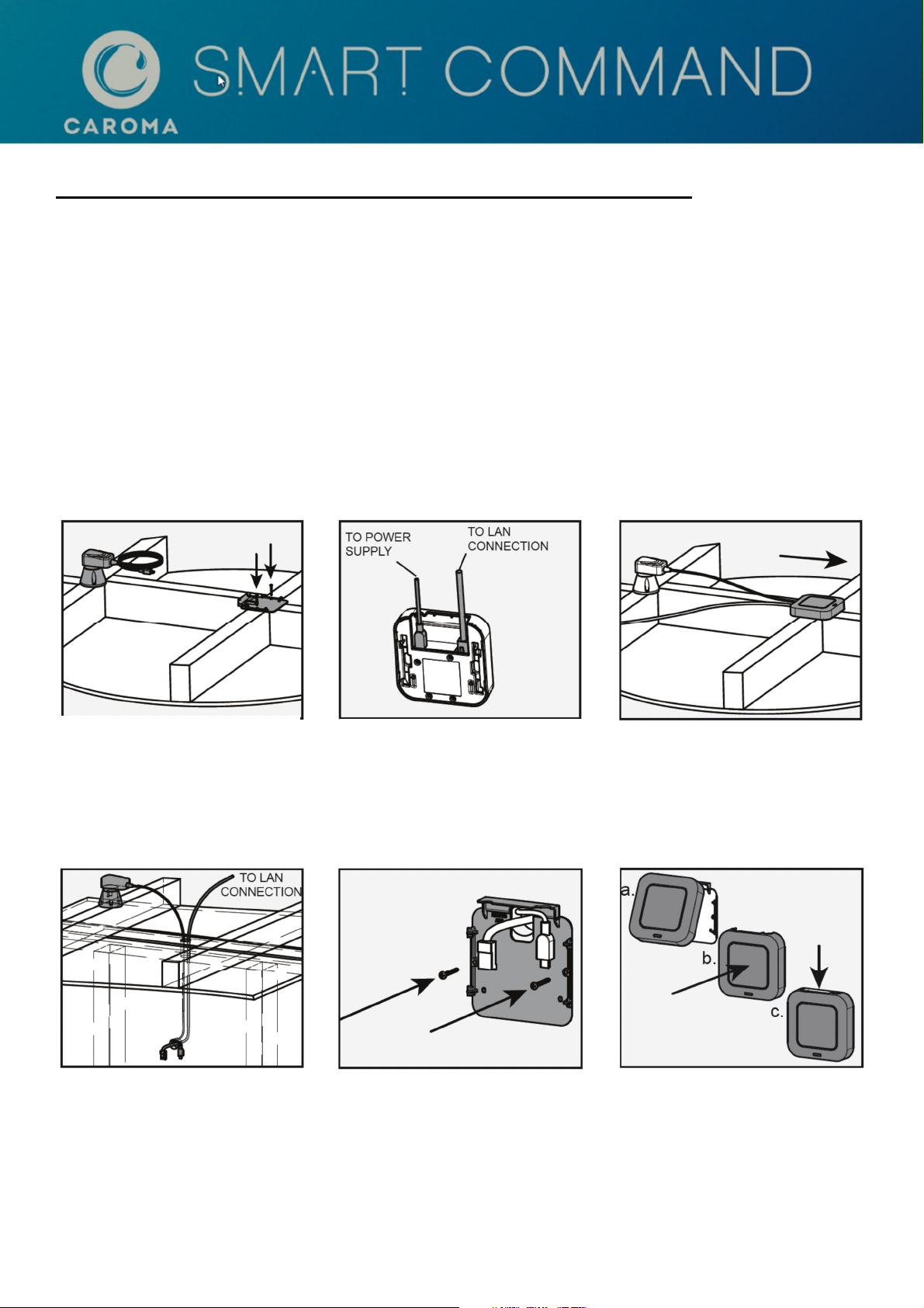
In Ceiling Installation:
1. Install mounting bracket to
ceiling joist with 4G pan head
screws. Ensure power point is
within 1.0 m of gateway
Wall Mount Installation:
2. Connect Power Supply and
Cat5e cable to Gateway.
Connect supplied Cat5e cable to
LAN connection.
3. Connect Gateway to
mounting bracket and slide
forward to lock into position.
1. Install power point within 1.4m of
gateway.
Run power and Cat5e cable
through 25mm wall hole. Trim any
conduit flush with wall.
2. Attach mounting bracket to wall
using 4g pan head screws (not
supplied)
3. Connect Power cable and
Cat5e cable into Gateway.
Engage Gateway onto mounting
bracket and slide down to lock.
Gateway commissioning instructions – See page 2
Page: 1 of 2 Smart Command - Gateway Installation Instructions IS1794_A
Page 2
Ethernet
Connection
- Network
Requirements
Commissioning Guide: 410100 Smart Command - Gateway
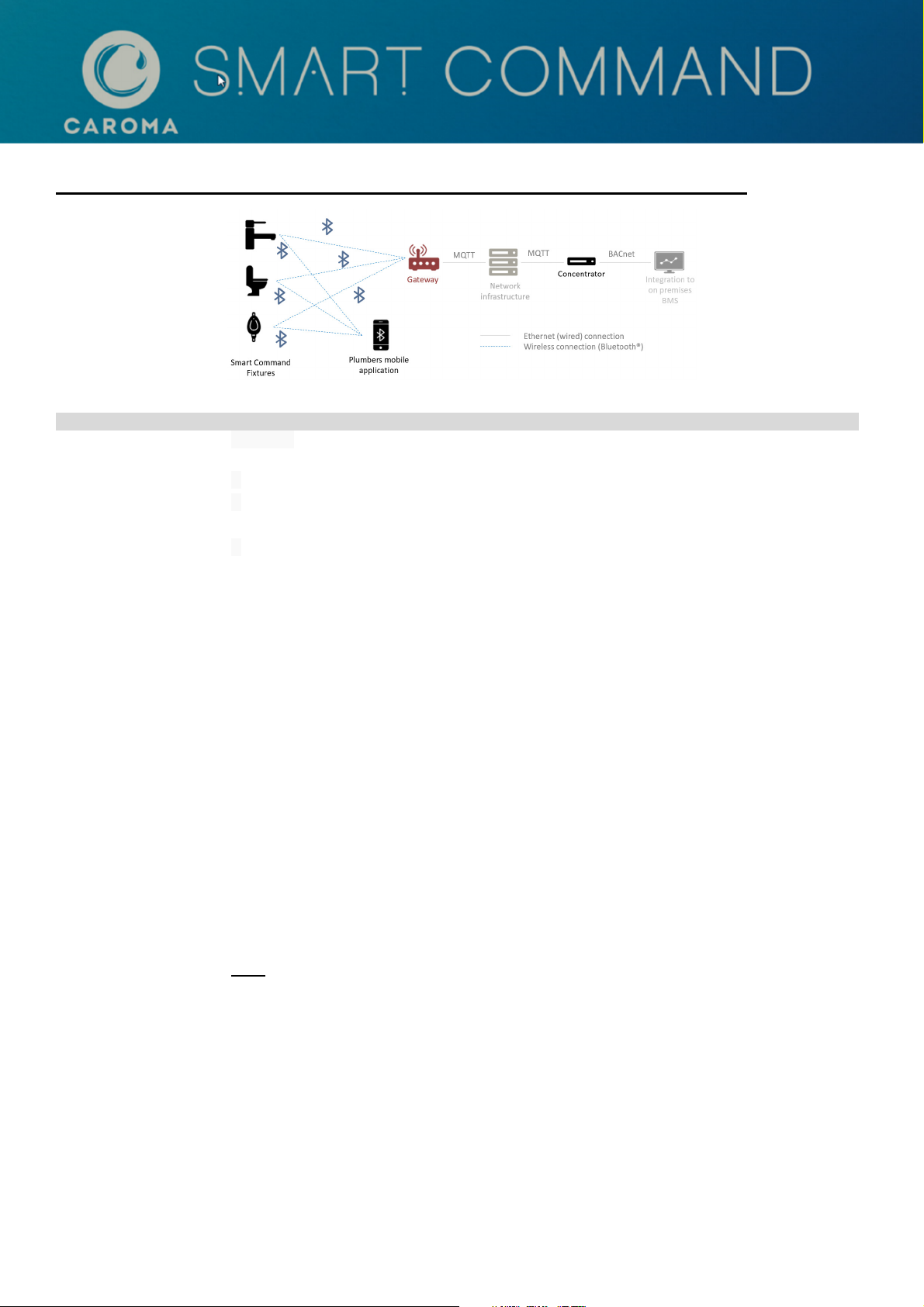
Example of a typical Building Management System configuration
Physical Connection • Cabled CAT-5e (RJ45) connection to the building’s network infrastructure to each Smart
Command Gateway. (Note: a 1.0m Cat5e patch lead is included)
Network Port Access
Network
Configuration - IP
Addresses
Gateway commissioning procedure:
1) Login to the Gateway via the inbuilt web-based configuration system by entering the Gateway’s IP address in to a
web browser.
(Note: The Gateway is set to DHCP by default, so IP address will be automatically assigned by DHCP server).
Enter the default device password: micas and click [Login].
2) On the “General” page fill in Gateway Name and its Location details, press [Save] to commit to device.
• Ports 8083 & 1883 open
• Have a network configured for DHCP (Automatic IP Address Allocation)
-or-
• Have the following information for fixed IP address allocation:
• IP address allocated to Smart Command Gateway
• IP address of network’s Gateway.
• IP Subnet mask
• MQTT Server IP address (typically the Concentrator) and default port.
3) Click “Password” to change the default password.
The password MUST be changed from its default to allow the Gateway to be paired with Concentrator
4) Click “BLE” button and select [Scan for Devices] to list the unconnected, visible BLE devices.
• Select the [Add Devices] button to connect the relevant Smart Command devices.
Devices will move up to the “Connected Devices” list.
• Enter the PIN for each device and press [Save] to pair the device with the Gateway.
• To complete the setup, select [Save Device List].
5) Click on “Network” button and enter the Network specific information such as MQTT Server (typically the
Concentrator) and select [MQTT pairing with Static Device ID option]. Press [Save] to commit to device.
6) Pair the Gateway with the Concentrator by navigating to the “General” page and select [Initiate Pairing].
The Gateway will communicate with the Concentrator and receive a unique “Pairing Token”.
The device is now ready to communicate with the Concentrator.
Note:
For detailed technical information and instructions on how to configure Caroma Smart Gateways with a BACnet
Concentrator (part # 410101), please refer to Smart Command Concentrator - Quick Start Guide (IS1795_A)
Page: 2 of 2 Smart Command - Gateway Installation Instructions IS1794_A
 Loading...