

Carolina NeuLog Photo Gate User Manual
NEULOG PHOTO GATE SENSOR GUIDE
NeuLog photo gate sensor
NUL-209 Carolina # 369638
The NeuLog photo gate sensor can be used for any science experiment or
activity which involves taking accurate velocity and/or acceleration
measurements especially in the field of Physics.
The sensor comes pre-calibrated so you can start experimentation right out
of the box using any of the following guides.
Just a few of the thousands of possible experimental subjects that can be
done with the NUL-209 sensors are: velocity/acceleration/distance
relationships, impulse, collisions, conservation of energy, force,
momentum, and many more.
The photo gate sensor uses an infrared beam which detects if an object is
passing through it. Therefore the sensor actively reads out as “open” or
“blocked”. While collecting data however there are several parameters to
truly customize your experiment:
Velocity with a single gate
Velocity with two gates
Acceleration with a single gate
Acceleration with two gates
Change in time between two gates
Velocities with timing cards.
Experiment customization:
The NeuLog photo gate sensor offers several different experimental
customization options. To access them; click on the “Experiment Setup”
button after your photo gate sensor has been detected. Note: Refer to the
guides below for more information on using NeuLog sensors
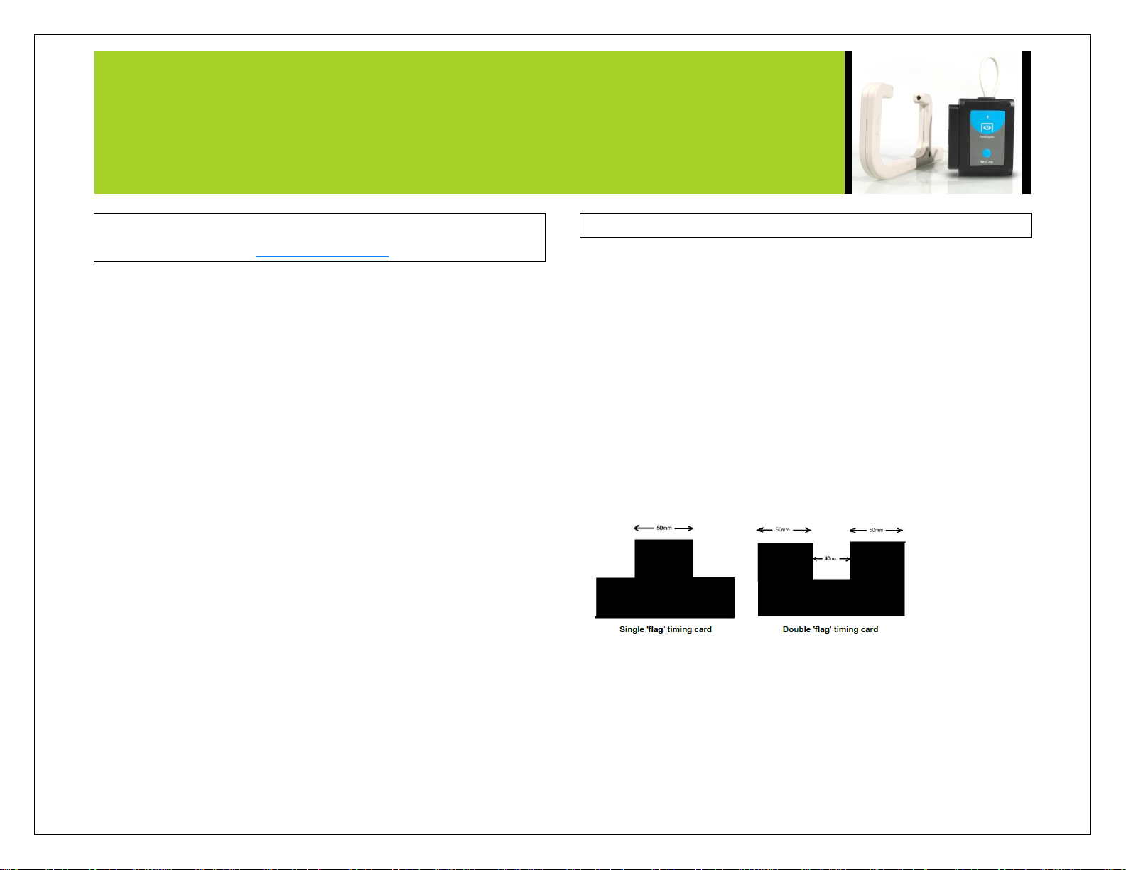
Timing cards:
Making timing cards is a unique option to further customize any experiment
with the NeuLog photo gate sensor. To make timing cards we recommend
cutting your desired shapes out of black plastic for the most accurate
readings though even plain paper will work just fine.
For example:
Velocity with a single gate:
Velocity with a single gate is the very basic velocity measurement using
only one photo gate sensor and any object with a known width.
NEULOG PHOTO GATE SENSOR GUIDE
1. Click the “Experiment Setup” button in the NeuLog software and
select “Velocity with a single gate”.
2. The graphic demonstrates the basic idea of what your experimental
setup should look like.
3. Measure and input the object width (in millimeters) into the text
field labeled “X[mm]”
4. Click “Save” and then you are ready to begin data collection.
Velocity with two gates:
The velocity with two gates option is ideal for experiments which examine
collisions between two objects of known width and mass.
1. Click the “Experiment Setup” button in the NeuLog software and
select “Velocity with two gates”.
2. The graphic demonstrates the basic idea of what your experimental
setup should look like.
3. Measure and input the width and mass for both of the objects
passing through the photo gate.
4. Assign each of your photo gate sensors to both the “Sensor A” and
“Sensor B” position.
5. Be sure to space the photo gates far enough apart to allow for a
collision between the two objects before they rebound back
through the photo gates.
6. Click “Save” and then you are ready to begin data collection
Acceleration with a single gate:
Acceleration with a single gate requires an object (or timing card) with two
flags (example shown above) with known widths.
1. Click the “Experiment Setup” button in the NeuLog software and
select “Acceleration with a single”.
2. The graphic demonstrates the basic idea of what your experimental
setup and timing card/object should look like.
3. Measure and input the width for both flags.
4. Click “Save” and then you are ready to begin data collection.
Acceleration with two gates:
Acceleration with two photo gates requires two Neulog photo gate sensors
and an object or timing card with a known width.
1. Click the “Experiment Setup” button in the NeuLog software and
select “Acceleration with two gates”.
2. The graphic demonstrates the basic idea of what your experimental
setup should look like.
3. Measure and input the width of your object (in millimeters) into
the text field labeled “X[mm]”.
4. Assign each of your photo gate sensors to both the “Sensor A” and
“Sensor B” position.
5. Click “Save” and then you are ready to begin data collection.
NEULOG PHOTO GATE SENSOR GUIDE
Change in time between two gates:
Change in time between two photo gates requires two Neulog photo gate
sensors and an object or timing card with a known width.
1. Click the “Experiment Setup” button in the NeuLog software and
select “Change in time between two gates”.
2. The graphic demonstrates the basic idea of what your experimental
setup should look like.
3. Measure and input the width of your object (in millimeters) into
the text field labeled “X[mm]”.
4. Assign each of your photo gate sensors to both the “Sensor A” and
“Sensor B” position.
5. Click “Save” and then you are ready to begin data collection.
Velocities with timing card:
Using a timing card with two equal width flags in the “Velocities with a
timing card” mode will measure the velocities without any more setup.
This mode is very useful for quick experiments with timing cards.
Quick start procedure:
PC or Mac Computer
Materials needed:
NUL-209 Photo Gate Sensor
USB-200 USB Module
A USB to mini USB cable (which comes with the USB-200)
Your photo gate sensor needs to be connected to a USB-200 module. The
USB-200 module then connects to a computer via a USB to mini-USB
cable. Please note that you cannot plug the photo gate sensor directly into
the computer.
Resident PC software and browser based software can be downloaded for
free at www.NeuLog.com/dowload as well as a full software user guide.
Note: Make sure not to download and install both types of software, they
will conflict on the computer.
Procedure:
1. Install the NeuLog software
2. Connect the USB-200 module to the PC or Mac
3. Connect the photo gate sensor to the USB-200 module (they
directly plug together). Please note there is no calibration required
for this sensor.
4. Open the NeuLog software.
5. Once a photo gate sensor logo appears on the left side of the screen
the probe has been automatically identified and you can begin
experimentation.
6. If the photo gate sensor is not automatically identified then click
the “Search for sensors” icon to find the sensor.
7. Select the “On-line experiment” button; this will open a graph
below.
8. Click on the “Module setup” button located on the photo gate
sensor icon in the module window to change the sensor settings if
need be.
9. Click on the experiment set up button to change the experiment
settings if need be (experiment duration for example).
 Loading...