

Page 1
C2616 FOUR-STUDENT WORKSTATION
ASSEMBLY INSTRUCTIONS
Page 2

TABLE OF CONTENTS
PAGE
REVISIONS TABLE…………………………………………………… ……………………………………………………………… .…………………..……….………..……….……………………… …………………..………………………………3
ASSEMBLY COMPONENTS………………………………………………… …………………………………………………………………. …………………..……….……….…………….……………… …………………………4
ASSEMBLY……………………………………………………… ……………………………………………………………. …………………..……….……………………………..……….………… …………………………………………………………… …………5
APRON ASSEMBLY………………………………………………… ……………………………………………………………… ….…………………..……….…..……….…………….………… ………………………………………………………6
LEG ASSEMBLY……………………………………………… ……………………………………………………………………. …………………..……….…………………………..……… .…………………………………………………………………… 8
ROD SOCKET ASSEMBLY………………………………………………… ……………………………………………………………… ….……………………...………………..……….…… ……………………………………………9
TOP ASSEMBLY……………………………………………… ……………………………………………………………………. …………………..……….…………………………………………… ……………………..………………………………… 10
FIXTURE ASSEMBLY…………………………………………………… ……………………………………………………………… .…………………..……….……………………………………..……… …………..…………………………11
SINK ASSEMBLY………………………………………………… ……………………………………………………………… ….…………………..……….……………………………………… …………..……………….……………………………… 11
BASE MOULDING ASSEMBLY…………………………………………… …………………………………………………………………… …….…………………..……….…………………………… ……………………12
PULL ASSEMBLY……………………………………………… ……………………………………………….………….…… ………………………………………………….…………. ……………………………………………………….……………. 12
Page 3

ASSEMBLY COMPONENTS
Items Included In Hardware Box
Part #
Part #
ASSEMBLY INSTRUCTIONS
1-HARDWARE BOX
11FT-RUBBER BASE
100283
16-SCREWS, 6X1/2” PTH SS
100064
4-NUT, HEX 5/16-18 STEEL
100044
1-SINK OUTLET/STAINER
100055
4-CARRIAGE BOLT 5/16X4-1/2
100447
1-SINK TRAP, PLASTIC ADJ
100056
4-WASHER, 5/16 FLAT
100451
1-SINK STOPPER 1 1/2 BLK
100112
12-SCREW, #10X1-1/2 PHIL TR.
100495
4-CLEAT, RAIL
100355
2-ELECTRICAL BOX, 3X2X2.5
100033
16-SCREWS, 8 X 3/4” PHIL
100649
2-GFI ELECTRICAL OUTLET
100034
8 - SHELF CLIPS
100027
8-SCREW, 6X1/2
100475
1-SILICONE SEALANT
100711
2-ROD SOCKET ASSEMBLIES
206505
2-APRON, W/COMP
206802
4-STAINLESS STEEL CORNERS
100057
2-FILLER,BASE 35X13
BF3513KRC
2-FIXTURE, L65-WSA-DIV
100074
2-LEGS FOR WINGS
L36
1-EPOXY SINK, L3 BLK
100691
1- EPOXY TOP, 48X66
100500-F2
2 - SHELVES, 22.188 X 14
200397-2218
2-LEG HARDWARE ASSY
206618
BOOT, LEVL, T-NUT
---
Original Created
2-14-07
JWD
REV DESCRIPTION DATE INITIAL
Page 4

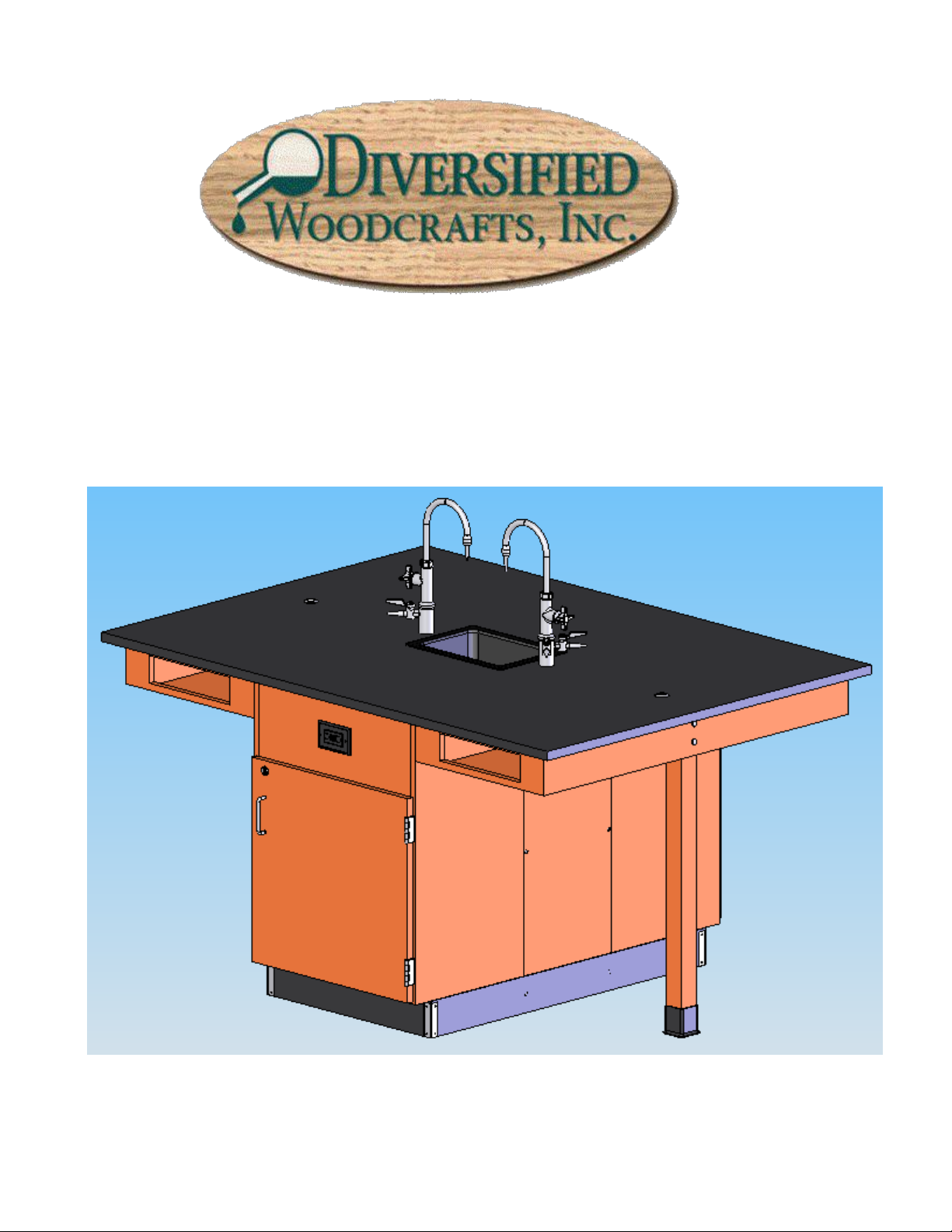
Assembly Instructions for
C2616 4-Student Workstation
Items not included but needed for assembly:
1. Phillips head screwdriver
2. ½”Wrench
3. Adjustable pliers
7. Liquid Nail or silicone adhesive (can be found in hardware stores)
Instructions:
1. Place the two base cabinets back to back in the desired location (See Figure 1A). Attach the 13” x 35”
filler panels to the cabinets by drilling pilot holes through the wooden cleats on the back of the
cabinets and attach with #10 x 1 ½ truss head screws (See Figure 1B)
Figure 1A
4. Tape measure
5. Utility knife
6. Contact cement
Figure 1B
2. Level the base cabinets and attach to the floor.
3. Apply the steel rail cleat to the wing assembly with the #8 x ¾” truss head screws.
Page 5

Figure 3A
Figure 3B
4. While one person is holding the wing in place, another person should be attaching the wing to the side
of the cabinet. It is important that the wing is supported until the table leg is in place. Make sure
the wing is flush with the top of the base cabinet.
Figure 4A
Figure 4B
Page 6

5. Screw the leveler to the leg and attach leg boot.
6. Line up the holes in the wing and the leg and insert 4-1/2” x 5/16” carriage bolt and tighten washer
and nut. Leg should be perpendicular to the wing. Use leveler on leg to level the wing with the
cabinet.
Figure 6A
Figure 6B
7. Repeat wing and leg instructions on the other side of the cabinet.
8. Do not apply pressure to the wings at this time. They are not strong enough to withstand weight
until the top is attached.
9. (If Applicable) Assemble the Rod Socket Assembly as shown in Figure 9A.
(If Applicable) Attach Rod Sockets to Top as shown in Figure 9B.
Figure 9A
Page 7

Figure 9B
10. Outline all of the top edges of the base unit and wings with the silicone adhesive caulk and place top
bottom side down on the unit. Be sure to center the top on all sides before the silicone dries. Let cure
for 24 hours.
11. Clean the top with water only. Be sure the area that the sink is dropped into is clean and dry.
12. Mount fixtures into place.
Page 8

13. Put a bead of silicone seal along the sink cutout on the top. Lower sink in place. Remove any excess
caulk that is displaced around the sink.
14. Cut the rubber base molding and attach using contact cement. After molding is in place, use the #6 x
½” SS screws to attach the stainless steel corner brackets on each corner over the base molding.
15. All water, electrical and gas connections should be performed by a trained professional.
(Note: When multiple units are assembled together apply silicone to the edge of the tops that are
being joined against each other. Remove any excess silicone. Allow 6-12 hours to cure.)
16. Reverse pulls to the exterior of unit as shown.
 Loading...