

Page 1
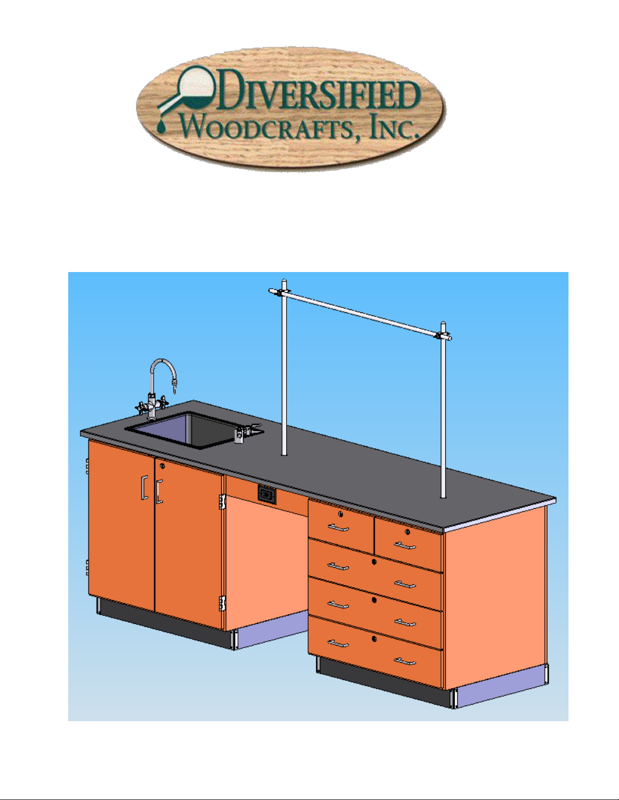
1116 INSTRUCTOR’S DESK
ASSEMBLY INSTRUCTIONS
Page 2

2
TABLE OF CONTENTS
PAGE
REVISONS TABLE………………………………………………………………………………………………………………………………………………………………………………………………………………….……………………………………………………………………………………..…………………………………1
ASSEMBLY COMPONENTS………………………………………………………………………………………………………………………………………………………………………………………………………………………………………………………………………………...………………2
BASE ASSEMBLY………………………………………………………………………………………………………………………………………………………………………………………………………………………………………………………………………………………………………………………………………………4
BACK PANEL ASSEMBLY…………………………………………………………………………………………………………………………………………………………………………………………………………………………………………………………………………….…………………………4
APRON RAIL ASSEMBLY………………………………………………………………………………………………………………………………………………………………………………………………………………………………………………….…………………………………….…………………5
TOP ASSEMBLY………………………………………………………………………………………………………………………………………………………………………………………………………………………………………………………………………………………………………………………………………………………5
SINK ASSEMBLY……………………………………………………………………………………………………………………………………………………………………………………………………………………………………………………………………………………………………………….…………………………………6
FIXTURE ASSEMBLY………………………………………………………………………………………………………………………………………………………………………………………………………………………………………………………………………………………………………………………………6
ROD SOCKET ASSEMBLY…………………………………………………………………………………………………………………………………………………………………………………………………………………………………………………………….…………………………………………6
BASE MOULDING ASSEMBLY………………………………………………………………………………………………………………………………………………………………………………………………………….………………………………..………..……………………………7
PULL ASSEMBLY………………………………………………………………………………………………………………………………………………………………………………………………………………………………………………………………………….………………………………………………………………………8
Page 3
3
Items Included In Hardware Box
Part #
Part #
1-ASSEMBLY INSTRUCTIONS
1-HARDWARE BOX
24 FT RUBBER BASE
100283
2-UPRIGHT RODS 3/4 DIA. X 36 L.
100004
1-ELECTRICAL BOX, 2X2.5
100033
1-CROSSBAR ROD, 3/4 DIA. X 48 L.
100006
1-GFI ELECTRIC OUTLET
100034
1-FIXTURE, L2900-132AWSA 90 DEG.-GAS
100048
4-SCREWS, 6X1/2 PPH
100475
1-FIXTURE,L414 HOT & COLD MIXING
100467
2-ROD SOCKET ASSEMBLY
206505
1-EPOXY SINK, L30 BLK
100699
2-ROD CLAMP ASSEMBLY
206506
1-EPOXY TOP, 30 X 96, BLK, FIXT
100497
6-STAINLESS STEEL CORNERS
100057
1-APRON WITH ELECT. 4.5X22
211289
24-STAINLESS STEEL SCREW, 6X1/2
100064
1-BACK PANEL, 94X35
212671
1-OUTLET/STRAINER EPOXY,BLK
100055
8-TRUSS HEAD SCREWS, 8 X 3/4
100649
1-PLASTIC ADJ SINK TRAP
100056
16-SCREW, WASHER FLAT HEAD #8X1 1/4
100478
1-SINK STOPPER 1 1/2, BLK
100112
2-CLEAT RAILS
100355
1-CLEAR SILICONE SEALENT
100711
---
Original Created
2-28-07
JWD
ASSEMBLY COMPONENTS
REV DESCRIPTION DATE INITIAL
Page 4

4
Assembly Instructions for
1116K and 1216K Instructor’s Desk
Items not included but needed for assembly:
1. Screwdrivers and Wrenches
2. Liquid Nail or silicone adhesive (can be found in hardware stores)
3. Contact Cement
4. Tape measure
Instructions:
1. Place the cupboard cabinet centered over the plumbing and gas.
2. Place the second cabinet in line with the cupboard cabinet leaving a 22” space between the cabinets
for the back panel.
3. Attach back panel to the back of the cabinets using the cleats and #8 x 1-1/4” phil pan head screws
provided. It is recommended that one person hold the back panel in place while a second person
actually attaches the panel. Make sure back panel is flush with the outside edges of the cabinets.
Page 5

5
4. Attach front apron between cabinets using the cleats and the 100649 #8 x ¾” screws provided. For
aesthetic purposes you may want to set the apron in 1”.
5. Outline the top of the base unit with the Liquid Nail or silicone adhesive and place top on the unit.
Let cure. Be sure to center the top on the base unit before the glue dries.
Page 6

6
6. Clean the top with water only. Be sure the area the sink is dropped in is clean and dry.
7. Put a bead of silicone seal along the cutout for the sink on the top. Lower sink in place.
8. Mount fixtures into place.
9. (If Applicable) Assemble the Rod Socket Assembly as shown in Figure 9A.
(If Applicable) Attach Rod Sockets to Top as shown in Figure 9B.
Figure 9A
Page 7

7
Figure 9B
10. Attach the rubber base molding using contact cement. After the molding is in place; screw stainless
steel corner brackets on each corner using the (100064) #6 x ½” screws provided, over the base molding.
Page 8

8
11. Reverse pulls to the exterior of unit as shown.
12. All water, electrical and gas connections should be performed by a trained professional.
P:\B Hawley\Web Downloads\Tech Manuals\705127,705128-1116K TECH MANUAL.doc
 Loading...